WO2020008572A1 - 鉄道車両用制御装置 - Google Patents
鉄道車両用制御装置 Download PDFInfo
- Publication number
- WO2020008572A1 WO2020008572A1 PCT/JP2018/025397 JP2018025397W WO2020008572A1 WO 2020008572 A1 WO2020008572 A1 WO 2020008572A1 JP 2018025397 W JP2018025397 W JP 2018025397W WO 2020008572 A1 WO2020008572 A1 WO 2020008572A1
- Authority
- WO
- WIPO (PCT)
- Prior art keywords
- command
- control unit
- voltage
- power conversion
- circuit
- Prior art date
- Legal status (The legal status is an assumption and is not a legal conclusion. Google has not performed a legal analysis and makes no representation as to the accuracy of the status listed.)
- Ceased
Links
Images



Classifications
-
- B—PERFORMING OPERATIONS; TRANSPORTING
- B60—VEHICLES IN GENERAL
- B60L—PROPULSION OF ELECTRICALLY-PROPELLED VEHICLES; SUPPLYING ELECTRIC POWER FOR AUXILIARY EQUIPMENT OF ELECTRICALLY-PROPELLED VEHICLES; ELECTRODYNAMIC BRAKE SYSTEMS FOR VEHICLES IN GENERAL; MAGNETIC SUSPENSION OR LEVITATION FOR VEHICLES; MONITORING OPERATING VARIABLES OF ELECTRICALLY-PROPELLED VEHICLES; ELECTRIC SAFETY DEVICES FOR ELECTRICALLY-PROPELLED VEHICLES
- B60L3/00—Electric devices on electrically-propelled vehicles for safety purposes; Monitoring operating variables, e.g. speed, deceleration or energy consumption
- B60L3/04—Cutting off the power supply under fault conditions
-
- B—PERFORMING OPERATIONS; TRANSPORTING
- B60—VEHICLES IN GENERAL
- B60L—PROPULSION OF ELECTRICALLY-PROPELLED VEHICLES; SUPPLYING ELECTRIC POWER FOR AUXILIARY EQUIPMENT OF ELECTRICALLY-PROPELLED VEHICLES; ELECTRODYNAMIC BRAKE SYSTEMS FOR VEHICLES IN GENERAL; MAGNETIC SUSPENSION OR LEVITATION FOR VEHICLES; MONITORING OPERATING VARIABLES OF ELECTRICALLY-PROPELLED VEHICLES; ELECTRIC SAFETY DEVICES FOR ELECTRICALLY-PROPELLED VEHICLES
- B60L15/00—Methods, circuits, or devices for controlling the traction-motor speed of electrically-propelled vehicles
- B60L15/20—Methods, circuits, or devices for controlling the traction-motor speed of electrically-propelled vehicles for control of the vehicle or its driving motor to achieve a desired performance, e.g. speed, torque, programmed variation of speed
- B60L15/2009—Methods, circuits, or devices for controlling the traction-motor speed of electrically-propelled vehicles for control of the vehicle or its driving motor to achieve a desired performance, e.g. speed, torque, programmed variation of speed for braking
-
- B—PERFORMING OPERATIONS; TRANSPORTING
- B60—VEHICLES IN GENERAL
- B60L—PROPULSION OF ELECTRICALLY-PROPELLED VEHICLES; SUPPLYING ELECTRIC POWER FOR AUXILIARY EQUIPMENT OF ELECTRICALLY-PROPELLED VEHICLES; ELECTRODYNAMIC BRAKE SYSTEMS FOR VEHICLES IN GENERAL; MAGNETIC SUSPENSION OR LEVITATION FOR VEHICLES; MONITORING OPERATING VARIABLES OF ELECTRICALLY-PROPELLED VEHICLES; ELECTRIC SAFETY DEVICES FOR ELECTRICALLY-PROPELLED VEHICLES
- B60L3/00—Electric devices on electrically-propelled vehicles for safety purposes; Monitoring operating variables, e.g. speed, deceleration or energy consumption
- B60L3/0023—Detecting, eliminating, remedying or compensating for drive train abnormalities, e.g. failures within the drive train
- B60L3/003—Detecting, eliminating, remedying or compensating for drive train abnormalities, e.g. failures within the drive train relating to inverters
-
- B—PERFORMING OPERATIONS; TRANSPORTING
- B60—VEHICLES IN GENERAL
- B60L—PROPULSION OF ELECTRICALLY-PROPELLED VEHICLES; SUPPLYING ELECTRIC POWER FOR AUXILIARY EQUIPMENT OF ELECTRICALLY-PROPELLED VEHICLES; ELECTRODYNAMIC BRAKE SYSTEMS FOR VEHICLES IN GENERAL; MAGNETIC SUSPENSION OR LEVITATION FOR VEHICLES; MONITORING OPERATING VARIABLES OF ELECTRICALLY-PROPELLED VEHICLES; ELECTRIC SAFETY DEVICES FOR ELECTRICALLY-PROPELLED VEHICLES
- B60L7/00—Electrodynamic brake systems for vehicles in general
- B60L7/10—Dynamic electric regenerative braking
- B60L7/16—Dynamic electric regenerative braking for vehicles comprising converters between the power source and the motor
-
- B—PERFORMING OPERATIONS; TRANSPORTING
- B60—VEHICLES IN GENERAL
- B60L—PROPULSION OF ELECTRICALLY-PROPELLED VEHICLES; SUPPLYING ELECTRIC POWER FOR AUXILIARY EQUIPMENT OF ELECTRICALLY-PROPELLED VEHICLES; ELECTRODYNAMIC BRAKE SYSTEMS FOR VEHICLES IN GENERAL; MAGNETIC SUSPENSION OR LEVITATION FOR VEHICLES; MONITORING OPERATING VARIABLES OF ELECTRICALLY-PROPELLED VEHICLES; ELECTRIC SAFETY DEVICES FOR ELECTRICALLY-PROPELLED VEHICLES
- B60L9/00—Electric propulsion with power supply external to the vehicle
- B60L9/16—Electric propulsion with power supply external to the vehicle using AC induction motors
- B60L9/18—Electric propulsion with power supply external to the vehicle using AC induction motors fed from DC supply lines
- B60L9/20—Electric propulsion with power supply external to the vehicle using AC induction motors fed from DC supply lines single-phase motors
-
- B—PERFORMING OPERATIONS; TRANSPORTING
- B60—VEHICLES IN GENERAL
- B60L—PROPULSION OF ELECTRICALLY-PROPELLED VEHICLES; SUPPLYING ELECTRIC POWER FOR AUXILIARY EQUIPMENT OF ELECTRICALLY-PROPELLED VEHICLES; ELECTRODYNAMIC BRAKE SYSTEMS FOR VEHICLES IN GENERAL; MAGNETIC SUSPENSION OR LEVITATION FOR VEHICLES; MONITORING OPERATING VARIABLES OF ELECTRICALLY-PROPELLED VEHICLES; ELECTRIC SAFETY DEVICES FOR ELECTRICALLY-PROPELLED VEHICLES
- B60L2200/00—Type of vehicles
- B60L2200/26—Rail vehicles
-
- B—PERFORMING OPERATIONS; TRANSPORTING
- B60—VEHICLES IN GENERAL
- B60L—PROPULSION OF ELECTRICALLY-PROPELLED VEHICLES; SUPPLYING ELECTRIC POWER FOR AUXILIARY EQUIPMENT OF ELECTRICALLY-PROPELLED VEHICLES; ELECTRODYNAMIC BRAKE SYSTEMS FOR VEHICLES IN GENERAL; MAGNETIC SUSPENSION OR LEVITATION FOR VEHICLES; MONITORING OPERATING VARIABLES OF ELECTRICALLY-PROPELLED VEHICLES; ELECTRIC SAFETY DEVICES FOR ELECTRICALLY-PROPELLED VEHICLES
- B60L2240/00—Control parameters of input or output; Target parameters
- B60L2240/40—Drive Train control parameters
- B60L2240/52—Drive Train control parameters related to converters
- B60L2240/527—Voltage
-
- Y—GENERAL TAGGING OF NEW TECHNOLOGICAL DEVELOPMENTS; GENERAL TAGGING OF CROSS-SECTIONAL TECHNOLOGIES SPANNING OVER SEVERAL SECTIONS OF THE IPC; TECHNICAL SUBJECTS COVERED BY FORMER USPC CROSS-REFERENCE ART COLLECTIONS [XRACs] AND DIGESTS
- Y02—TECHNOLOGIES OR APPLICATIONS FOR MITIGATION OR ADAPTATION AGAINST CLIMATE CHANGE
- Y02T—CLIMATE CHANGE MITIGATION TECHNOLOGIES RELATED TO TRANSPORTATION
- Y02T10/00—Road transport of goods or passengers
- Y02T10/60—Other road transportation technologies with climate change mitigation effect
- Y02T10/64—Electric machine technologies in electromobility
-
- Y—GENERAL TAGGING OF NEW TECHNOLOGICAL DEVELOPMENTS; GENERAL TAGGING OF CROSS-SECTIONAL TECHNOLOGIES SPANNING OVER SEVERAL SECTIONS OF THE IPC; TECHNICAL SUBJECTS COVERED BY FORMER USPC CROSS-REFERENCE ART COLLECTIONS [XRACs] AND DIGESTS
- Y02—TECHNOLOGIES OR APPLICATIONS FOR MITIGATION OR ADAPTATION AGAINST CLIMATE CHANGE
- Y02T—CLIMATE CHANGE MITIGATION TECHNOLOGIES RELATED TO TRANSPORTATION
- Y02T10/00—Road transport of goods or passengers
- Y02T10/60—Other road transportation technologies with climate change mitigation effect
- Y02T10/72—Electric energy management in electromobility
Definitions
- the present invention relates to a railway vehicle control device.
- the power conversion system disclosed in Patent Literature 1 includes an inverter device as a power conversion unit, and includes an inverter control unit as a control unit that controls the power conversion unit.
- the power converter converts the power supplied from the current collector connected to the primary terminal and supplies the power to the motor connected to the secondary terminal.
- the power converter converts AC power supplied from the electric motor into DC power.
- the voltage on the power collection unit side of the power conversion unit is changed to a power conversion unit mounted on another electric railway vehicle. It is adjusted to a range suitable for supplying power to the system.
- the power conversion unit is stopped when an emergency brake is applied while the electric railway vehicle is running, or when the power conversion unit needs to be protected by detecting an overvoltage or an overcurrent of the power conversion unit. Further, after stopping the power conversion unit, it is conceivable to open a contactor provided between the power collection device and the power conversion unit and electrically disconnect the power conversion unit from the power collection device. In the power conversion system disclosed in Patent Literature 1, when the power conversion unit is stopped and the contactor is opened, even after the power conversion unit is stopped, the power conversion unit stops moving toward the power conversion unit due to mechanical operation delay. Current may continue to flow. As a result, an overvoltage may occur on the primary side of the power conversion unit.
- the present invention has been made in view of the above circumstances, and has as its object to provide a railway vehicle control device capable of suppressing overvoltage on the primary side of a power conversion unit.
- a railway vehicle control device of the present invention includes a torque control unit and a circuit control unit.
- the torque control unit controls the operation of a switching element included in a power conversion unit that performs bidirectional power conversion between a primary side to which a power supply is connected and a secondary side to which a motor is connected, thereby reducing the torque of the motor. Adjust.
- the circuit control unit acquires the voltage on the primary side of the power conversion unit, and operates the step-down circuit connected in parallel to the primary side when the voltage on the primary side is equal to or higher than the reference voltage.
- the torque control unit stops the operation of the switching element of the power conversion unit.
- the circuit control unit operates the step-down circuit.
- the railway vehicle control device upon acquiring the stop command, operates the step-down circuit. Therefore, it is possible to suppress the overvoltage on the primary side of the power conversion unit.
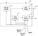
- 1 is a block diagram showing a configuration of a power conversion system for a railway vehicle according to an embodiment of the present invention.
- 1 is a block diagram illustrating a configuration of a railway vehicle control device according to an embodiment.
- 9 is a flowchart illustrating an example of an operation of an overvoltage suppression process performed by the railway vehicle control device according to the embodiment.
- a power conversion system for a railway vehicle (hereinafter referred to as a power conversion system) 1 according to the embodiment of the present invention shown in FIG. 1 is mounted on an electric railway vehicle.
- An operation command is input to the power conversion system 1 from a cab of the electric railway vehicle.
- the operation command includes a powering command for instructing acceleration of the electric railway vehicle or a brake command for instructing deceleration of the electric railway vehicle.
- the power conversion system 1 acquires DC power from an unillustrated substation which is an example of a DC power supply via the overhead wire 2 which is an example of a power supply line.
- the power conversion system 1 drives the motor 8 by converting the DC power into AC power and supplying the AC power to the motor 8.
- the electric motor 8 is driven, the propulsion of the electric railway vehicle is obtained.
- the operation command includes a brake command, that is, at the time of braking, the power conversion system 1 converts the power generated by the electric motor 8 operating as a generator into DC power, and mounts the DC power on another electric railway vehicle via the overhead line 2. To the power conversion system 1.
- the power conversion system 1 is an example of a power collection device, and includes a pantograph 3 that obtains DC power from a substation via an overhead line 2, and power conversion that converts DC power into AC power and supplies the AC power to a motor 8.
- a unit 12 is provided.
- the power conversion system 1 also controls the power conversion unit 12 and controls the contactors 4 and 5 that switch the electrical connection between the pantograph 3 and the power conversion unit 12. ) 20.
- the control device 20 operates the chopper circuit 14 in addition to the control described above.
- the chopper circuit 14 is provided as an example of a step-down circuit, and is connected to the pantograph 3 of the power conversion unit 12 in parallel with the pantograph 3.
- the chopper circuit 14 includes a switching element 15 and a brake resistor 16 connected in series.
- the control device 20 increases the conduction ratio of the switching element 15 included in the chopper circuit 14. As a result, the power output from the power converter 12 is consumed by the chopper circuit 14, and the voltage of the filter capacitor 11 connected to the primary side of the power converter 12 is reduced.
- the power conversion system 1 further includes a voltage detection unit 13 that detects a voltage EFC of the filter capacitor 11 and a current detection unit 9 that detects each of U-phase, V-phase, and W-phase currents flowing through the motor 8.
- the pantograph 3 rises in accordance with the operation on the cab and comes into contact with the overhead wire 2. Thereafter, the control device 20 turns on the contactor 5 with the contactor 4 opened. A resistor 6 is connected to the contactor 5 in series, and power is supplied from the pantograph 3 to the power converter 12 via the contactor 5 and the resistor 6, so that an inrush current may flow through the power converter 12. Is suppressed. Thereafter, when the voltage EFC of the filter capacitor 11 reaches the reference input voltage, the control device 20 turns on the contactor 4 and opens the contactor 5.
- the control device 20 performs the control described below based on the operation command signal S1 and the stop command signal S2.
- the operation command signal S1 is a signal according to the operation of the master controller in the cab, and indicates a powering notch or a brake notch.
- the stop command signal S2 is assumed to be input from an abnormality detection device that detects an abnormality of the electric railway vehicle.
- the stop command signal S2 becomes H (High) level when instructing to turn off the switching element of the power conversion unit 12, and becomes L (Low) level when instructing to maintain the switching operation of the power conversion unit 12.
- the abnormality detection device detects various abnormalities such as an overvoltage and an overcurrent of the power conversion unit 12, an overcurrent of the electric motor 8, and a state where the pantograph 3 is separated from the overhead line 2.
- the control device 20 supplies the power conversion unit 12 from the pantograph 3 via the contactor 4 and the smoothing reactor 7.
- the switching elements of the power conversion unit 12 are turned on and off so as to convert DC power into AC power.
- the power converter 12 supplies the AC power to the electric motor 8 connected to the secondary side.
- the control device 20 calculates a target torque for obtaining the target acceleration indicated by the powering notch, and calculates an actual torque of the electric motor 8 from a current flowing through the electric motor 8. Then, control device 20 controls the operation of the switching element of power conversion unit 12 in order to bring the actual torque closer to the target torque.
- a three-phase induction motor is used as the motor 8, and the control device 20 acquires a current value flowing through the motor 8 from a current detection unit 9 that detects a U-phase, V-phase, and W-phase current flowing through the motor 8.
- the control device 20 causes the power conversion unit 12 to convert regenerative power generated by the motor 8 operating as a generator into DC power.
- the operation of the switching element of the power conversion unit 12 is controlled.
- the DC power is supplied to the power conversion system 1 mounted on another electric railway vehicle via the overhead line 2.
- the voltage EFC of the filter capacitor 11 needs to be higher than the overhead line voltage.
- the voltage EFC is too large than the overhead wire voltage, an overvoltage occurs in the overhead wire voltage.
- control device 20 operates chopper circuit 14 when voltage EFC is equal to or higher than the reference voltage.
- the chopper circuit 14 has a switching element 15 and a brake resistor 16 connected in series.
- the control device 20 has a positive correlation with the voltage EFC, and adjusts the duty ratio of the switching element 15 based on the duty ratio that changes with the time of the voltage EFC.
- the control device 20 operates the chopper circuit 14 without depending on the magnitude relationship between the voltage EFC and the reference voltage. In other words, when the operation command signal S1 indicates a power running notch and the stop command signal S2 goes to the H level, the control device 20 controls the switching element 15 of the chopper circuit 14 even if the voltage EFC is lower than the reference voltage. Increase the flow rate to greater than zero.
- the control device 20 includes a torque control unit 21 that switches on and off a switching element included in the power conversion unit 12, a contactor control unit 22 that turns on or off the contactors 4 and 5, and a chopper circuit 14. It includes a circuit control unit 23 that operates and a target calculation unit 24 that calculates a target torque of the electric motor 8. The outline of each part of the control device 20 will be described.
- the target calculation unit 24 calculates a target torque of the electric motor 8 required to obtain a target acceleration indicated by the power running notch or a target deceleration indicated by the brake command, and sends the target torque to the torque control unit 21.
- the torque controller 21 calculates the actual torque or the regenerative torque of the electric motor 8 from the phase current detected by the current detector 9.
- the torque control unit 21 controls the operation of the switching element of the power conversion unit 12 so that the actual torque or the regenerative torque approaches the target torque. Further, when the operation command signal S1 indicates a power running notch and the stop command signal S2 becomes H level, the torque control unit 21 turns off the switching element of the power conversion unit 12.
- the circuit controller 23 obtains the voltage EFC of the filter capacitor 11 from the voltage detector 13 and, when the voltage EFC is equal to or higher than the reference voltage, switches the chopper circuit 14 based on the conduction ratio having a positive correlation with the voltage EFC.
- the chopper circuit 14 is operated by adjusting the flow rate of the element 15.
- the circuit control unit 23 sets a duty ratio having a positive correlation with the voltage EFC regardless of the magnitude relationship between the voltage EFC and the reference voltage.
- the chopper circuit 14 is operated by switching on and off the switching element 15 of the chopper circuit 14. Note that the circuit control unit 23 can set a limit on the time during which the chopper circuit 14 operates.
- the torque control unit 21 switches on / off of a switching element included in the power conversion unit 12 according to the operation command signal S1 and the stop command signal S2. Specifically, when the operation command signal S1 indicates a power running notch and the stop command signal S2 is at the L level, the torque control unit 21 controls the switching element of the power conversion unit 12 to bring the actual torque close to the target torque. Control behavior. When the operation command signal S1 includes the brake command and the stop command signal S2 is at the L level, the torque control unit 21 controls the operation of the switching element included in the power conversion unit 12 to bring the regenerative torque closer to the target torque. I do. Further, when the stop command signal S2 becomes H level, the torque control unit 21 turns off the switching element of the power conversion unit 12.
- the contactor control unit 22 turns on the contactor 5 with the contactor 4 opened. Thereafter, the contactor control unit 22 turns on the contactor 4 and then opens the contactor 5. That is, during operation of the electric railway vehicle, the contactor 4 is turned on and the contactor 5 is opened.
- the stop command signal S2 becomes H level during operation of the electric railway vehicle, the contactor control unit 22 opens the contactor 4. Thereafter, the closing operation of the contactors 4 and 5 is the same as when the electric railway vehicle starts operating.
- the circuit control unit 23 has a positive correlation with the voltage EFC of the filter capacitor 11 detected by the voltage detection unit 13 when the operation command signal S1 indicates a brake notch and the stop command signal S2 is at the L level.
- the duty ratio of the switching element 15 included in the chopper circuit 14 is adjusted based on the duty ratio of the EFC that changes with time. Specifically, when the voltage EFC of the filter capacitor 11 becomes equal to or higher than the reference voltage E1, the conduction ratio of the switching element 15 included in the chopper circuit 14 is adjusted based on the conduction ratio described above.
- An example of the conduction ratio having a positive correlation with the voltage EFC is shown by a thick solid line in FIG. The conduction ratio indicated by the thick solid line in FIG.
- the conduction ratio when the voltage EFC is equal to or lower than the reference voltage E1 is defined as a minimum conduction ratio R MIN .
- the conduction ratio when the voltage EFC is equal to or higher than the voltage E2 is defined as a maximum conduction ratio R MAX .
- the timing at which the circuit control unit 23 operates the chopper circuit 14 is not limited to the case where the above-described operation command signal S1 indicates a brake notch.
- the circuit control unit 23 determines that the voltage EFC is positive regardless of the magnitude relationship between the voltage EFC of the filter capacitor 11 and the reference voltage E1.
- the duty ratio of the switching element 15 of the chopper circuit 14 is adjusted based on the duty ratio of the voltage EFC that changes with time.
- the circuit control unit 23 has a positive correlation with the voltage EFC.
- the conduction ratio of the switching element 15 is adjusted based on the conduction ratio.
- An example of a conduction ratio having a positive correlation with the voltage EFC when the operation command signal S1 indicates a power running notch and the stop command signal S2 is at the H level is shown by a thin solid line in FIG.
- the conduction ratio indicated by a thin solid line in FIG. 3 increases from the minimum conduction ratio R MIN to the maximum conduction ratio R ′ MAX as the voltage EFC increases.
- the operation command signal S1 indicates a power running notch
- the stop command signal S2 is at the H level
- the conduction ratio when the voltage EFC matches the reference voltage E1 is R1.
- the duty ratio is the minimum duty ratio R MIN as described above.
- the operation command signal S1 indicates a power running notch and the flow rate when the stop command signal S2 is at the H level is determined so that R1> minimum flow rate R MIN .
- the conduction ratio is determined, so that when the stop command signal S2 is acquired, the voltage EFC is quickly reduced. It is possible to do.
- the stop command signal S2 indicates an H level
- the maximum duty ratio R'MAX indicates an operation command signal S1 indicates a brake notch.
- the value is set to a value sufficiently smaller than the maximum conduction ratio R MAX when the command signal S2 is at the L level.
- the pantograph 3 remains in a state from when the switching element of the power conversion unit 12 is turned off until the contactor 4 is opened. Electric power obtained from the substation via the overhead line 2 is supplied to the chopper circuit 14 and may be consumed by the brake resistor 16. Therefore, by setting the maximum conduction ratio R ′ MAX to a value sufficiently smaller than the maximum conduction ratio R MAX , the chopper circuit 14 is prevented from consuming the power acquired by the pantograph 3.
- control device 20 starts the overvoltage suppression process shown in FIG.
- the operation command signal S1 indicates a brake notch, that is, when the operation command signal S1 does not indicate a powering notch
- the circuit control unit 23 compares the voltage EFC of the filter capacitor 11 with the reference voltage E1. (Step S12).
- the processing of steps S11 and S12 is repeated.
- the circuit control unit 23 When the operation command signal S1 indicates a brake notch (Step S11; N) and the voltage EFC is equal to or higher than the reference voltage E1 (Step S12; Y), the circuit control unit 23 has a positive correlation with the voltage EFC, and The duty ratio of the switching element 15 of the chopper circuit 14 is adjusted based on the duty ratio of the EFC that changes with time with time (step S13). Upon completion of the process in the step S13, the process returns to the step S12, and the voltage EFC is compared with the reference voltage E1.
- Step S11; Y When the operation command signal S1 indicates a power running notch (step S11; Y) and the stop command signal S2 is at the L level (step S14; N), the processing of steps S11 and S14 is repeated.
- the operation command signal S1 indicates a power running notch (Step S11; Y) and the stop command signal S2 is at the H level (Step S14; Y), the processes of Steps S15, S16, and S17 described later are performed in parallel.
- the torque control unit 21 turns off the switching element of the power conversion unit 12 (Step S15). Further, the contactor control unit 22 opens the contactor 4 (Step S16).
- the circuit control unit 23 adjusts the duty ratio of the switching element 15 of the chopper circuit 14 (Step S17). Specifically, in step S17, the circuit control unit 23 switches the switching element 15 included in the chopper circuit 14 on and off at a conduction ratio having a positive correlation with the voltage EFC. If the operation time at the minimum flow rate is less than the predetermined time (step S18; N), the processing of step S17 is repeated. Specifically, the circuit control unit 23 has a time measurement circuit, measures the time during which the flow rate is set to the minimum flow rate, and determines whether the measurement time is equal to or longer than a certain time.
- Step S19 the circuit control unit 23 stops the chopper circuit 14 (Step S19). Specifically, in step S19, the circuit control unit 23 turns off the switching element 15 of the chopper circuit 14.
- the control device 20 ends the overvoltage suppression processing. Thereafter, as described above, when the contactor 5 is opened after the contactor 5 and the contactor 4 are turned on in this order and an operation command is input, the control device 20 starts the process of step S11 again.
- the filter capacitor 11 when the stop command is acquired, the filter capacitor 11 is operated by operating the chopper circuit 14 without depending on the magnitude relationship between the voltage EFC and the reference voltage. Overvoltage can be suppressed.
- FIG. 5 is a diagram illustrating a configuration example of hardware of the control device for a railway vehicle according to the embodiment.
- the railway vehicle control device 20 includes a processor 31, a memory 32, and an interface 33 as hardware configurations for controlling the respective units. Each function of these devices is realized by the processor 31 executing a program stored in the memory 32.
- the interface 33 connects each device and establishes communication, and may include a plurality of types of interfaces as necessary.
- FIG. 5 illustrates an example in which the railway vehicle control device 20 includes one processor 31 and one memory 32, a plurality of processors 31 and a plurality of memories 32 may execute each function in cooperation with each other.
- the main part that has the processor 31, the memory 32, and the interface 33 and performs the control processing can be realized by using a normal computer system without using a dedicated system.
- a computer program for executing the above-described operation is stored in a computer-readable recording medium (such as a flexible disk, CD-ROM, or DVD-ROM) and distributed, and the computer program is installed in the computer.
- the railway vehicle control device 20 that executes the above-described processing may be configured.
- the computer program may be stored in a storage device of a server device on a communication network, and downloaded by an ordinary computer system to configure the railway vehicle control device 20.
- the functions of the railway vehicle control device 20 are realized by sharing an OS (operating system) with an application program or by cooperation between the OS and the application program, only the application program portion is recorded on a recording medium or a storage device. May be stored.
- OS operating system
- the computer program may be posted on a bulletin board (BBS: Bulletin Board System) on a communication network, and the computer program may be distributed via the communication network. Then, the above-described processing may be executed by activating the computer program and executing it in the same manner as other application programs under the control of the OS.
- BSS Bulletin Board System
- the circuit configuration of the power conversion system 1 is arbitrary, and is not limited to the above example.
- the contactors 4 and 5 may be connected in series, and the resistor 6 may be connected to the contactor 5 in parallel.
- the contactor 5 is turned on after the contactor 4 is turned on. That is, the contactors 4 and 5 are turned on during the operation of the electric railway vehicle.
- the stop command signal S2 becomes H level, both the contactors 4 and 5 are opened.
- the power collection system of the power conversion system 1 is not limited to the overhead line system described above, and any system that acquires power from a substation can be adopted.
- a surface power collection system, a third rail system, and the like can be given.
- the current collector is any device that acquires power from the overhead wire 2, and is, for example, a trolley pole, a bugel, or the like.
- the operation command may include a coasting command in addition to the powering command and the brake command.
- the circuit control unit 23 operates the chopper circuit 14.
- the configuration of the control device 20 is not limited to the above-described example, and may be any configuration that suppresses the overvoltage of the filter capacitor 11.
- the function of the contactor control unit 22 may be provided as a contactor control device separately from the control device 20. In this case, the contactor control device opens the contactor 4 when the stop command signal S2 becomes H level.
- the conduction ratio is calculated according to any function, table, or the like having a positive correlation with voltage EFC.
- the conduction ratio is calculated based on a linear function, a quadratic function, or the like that uses the voltage of the filter capacitor 11 as a variable.
- the step-down circuit provided on the pantograph 3 side of the power conversion unit 12 is not limited to the chopper circuit 14, and any step-down circuit can be provided.
- a switching regulator may be provided.
- the condition for stopping the chopper circuit 14 is not limited to the example of step S18 in FIG.
- a voltage detector for detecting the voltage on the pantograph 3 side from the contactor 4 is further provided, and the chopper circuit 14 is stopped based on the voltage on the pantograph 3 side of the contactor 4 detected by the voltage detector. Is also good.
- the operation of the chopper circuit 14 may be stopped when the voltage of the contactor 4 on the side of the pantograph 3 is within a desired range for a predetermined time or more.
Landscapes
- Engineering & Computer Science (AREA)
- Power Engineering (AREA)
- Transportation (AREA)
- Mechanical Engineering (AREA)
- Life Sciences & Earth Sciences (AREA)
- Sustainable Development (AREA)
- Sustainable Energy (AREA)
- Electric Propulsion And Braking For Vehicles (AREA)
Abstract
制御装置(20)は、トルク制御部(21)、および、回路制御部(23)を備える。トルク制御部(21)は、運転指令に応じて電力変換部が有するスイッチング素子のオンオフを切り替える。運転指令がブレーキ指令を含み、フィルタコンデンサの電圧が基準電圧以上である場合に、回路制御部(23)は、フィルタコンデンサの電圧と正の相関を有し、フィルタコンデンサの電圧の時間変化に伴って時間変化する通流率で、降圧回路を動作させる。また、運転指令が力行指令を含む場合に、回路制御部(23)は、停止指令を取得すると、フィルタコンデンサの電圧と基準電圧との大小関係に依存せず、降圧回路を動作させる。
Description
この発明は、鉄道車両用制御装置に関する。
電気鉄道車両に搭載されるパンタグラフ、集電靴等の集電装置は、架線、第三軌条等の電力供給線に接触することで、電力を取得する。電気鉄道車両に搭載される電力変換システムは、集電装置が取得した電力を、交流電力に変換し、交流電動機に供給する。交流電力の供給を受けることで、交流電動機が駆動されると、電気鉄道車両の推進力が得られる。またブレーキ時には、電力変換システムは、発電機として動作する交流電動機から供給される電力を、直流電力に変換し、電力供給線を介して他の電気鉄道車両に搭載される電力変換システムに供給する。電力変換システムの一例が、特許文献1に開示されている。特許文献1に開示される電力変換システムは、電力変換部としてインバータ装置を備え、電力変換部を制御する制御部としてインバータ制御部を備える。電力変換部は、一次端子に接続された集電装置から供給された電力を変換して、二次端子に接続された電動機に供給する。一方、ブレーキ時には、電力変換部は、電動機から供給される交流電力を、直流電力に変換する。また、ブレーキ時には、電力変換部の集電装置の側に設けられたチョッパ装置を動作させることで、電力変換部の集電装置の側の電圧が、他の電気鉄道車両に搭載される電力変換システムに電力を供給するために適した範囲に調節される。
電気鉄道車両の走行中に緊急ブレーキがかかった場合、電力変換部の過電圧、過電流等の検出により電力変換部の保護が必要となった場合等に、電力変換部が停止される。また電力変換部の停止後には、集電装置と電力変換部との間に設けられる接触器を開放して、電力変換部を集電装置から電気的に切り離すことが考えられる。特許文献1に開示される電力変換システムにおいて、電力変換部を停止して、接触器を開放すると、機械的動作の遅れによって、電力変換部停止後も、集電装置から電力変換部に向かって電流が流れ続けることがある。その結果、電力変換部の一次側において過電圧が生じることがある。
本発明は上述の事情に鑑みてなされたものであり、電力変換部の一次側における過電圧を抑制可能な鉄道車両用制御装置を提供することを目的とする。
上記目的を達成するために、本発明の鉄道車両用制御装置は、トルク制御部、および回路制御部を備える。トルク制御部は、電源が接続される一次側と、電動機が接続される二次側との間で双方向の電力変換を行う電力変換部が有するスイッチング素子の動作を制御して電動機のトルクを調節する。回路制御部は、電力変換部の一次側の電圧を取得し、一次側の電圧が基準電圧以上である場合に、一次側に並列に接続された降圧回路を動作させる。トルク制御部は、電力変換部が有するスイッチング素子のオフを指示する停止指令を取得すると、電力変換部が有するスイッチング素子の動作を停止する。回路制御部は、停止指令を取得すると、降圧回路を動作させる。
本発明によれば、鉄道車両用制御装置は、停止指令を取得すると、降圧回路を動作させる。従って、電力変換部の一次側における過電圧を抑制可能となる。
以下、本発明の実施の形態に係る鉄道車両用制御装置について図面を参照して詳細に説明する。なお図中、同一または同等の部分には同一の符号を付す。
図1に示す本発明の実施の形態に係る鉄道車両用電力変換システム(以下、電力変換システムという)1は、電気鉄道車両に搭載される。電力変換システム1には、電気鉄道車両の運転台から運転指令が入力される。運転指令は、電気鉄道車両の加速を指示する力行指令、または、電気鉄道車両の減速を指示するブレーキ指令を含む。運転指令が力行指令を含む場合、すなわち、力行時に、電力変換システム1は、電力供給線の一例である架線2を介して、直流電源の一例である図示しない変電所から直流電力を取得する。そして、電力変換システム1は、該直流電力を交流電力に変換し、電動機8に供給することで、電動機8を駆動する。電動機8が駆動されると、電気鉄道車両の推進力が得られる。運転指令がブレーキ指令を含む場合、すなわち、ブレーキ時に、電力変換システム1は、発電機として動作する電動機8で生じた電力を直流電力に変換し、架線2を介して他の電気鉄道車両に搭載される電力変換システム1に供給する。
電力変換システム1は、集電装置の一例であって、架線2を介して変電所から直流電力を取得するパンタグラフ3、および、直流電力を交流電力に変換して、電動機8に供給する電力変換部12を備える。また電力変換システム1は、電力変換部12を制御し、パンタグラフ3と電力変換部12との間の電気的接続を切り替える接触器4,5を制御する鉄道車両用制御装置(以下、制御装置という)20を備える。さらに制御装置20は、上述の制御に加えて、チョッパ回路14を動作させる。チョッパ回路14は、降圧回路の一例として設けられ、電力変換部12のパンタグラフ3の側にパンタグラフ3に並列に接続される。詳細には、チョッパ回路14は、直列に接続されたスイッチング素子15およびブレーキ抵抗16を備える。制御装置20は、チョッパ回路14が有するスイッチング素子15の通流率を増大させる。その結果、電力変換部12が出力する電力がチョッパ回路14で消費され、電力変換部12の一次側に接続されたフィルタコンデンサ11の電圧が低減される。さらに、電力変換システム1は、フィルタコンデンサ11の電圧EFCを検出する電圧検出部13、および、電動機8に流れるU相、V相、W相の各相電流を検出する電流検出部9を備える。
電気鉄道車両が運行を開始する際には、運転台での操作に応じてパンタグラフ3が上昇して、架線2に接触する。その後、制御装置20は、接触器4を開放した状態で、接触器5を投入する。接触器5には抵抗6が直列に接続されており、パンタグラフ3から接触器5および抵抗6を介して電力変換部12に電力が供給されるため、電力変換部12に突入電流が流れることが抑制される。その後、フィルタコンデンサ11の電圧EFCが基準となる投入電圧に達すると、制御装置20は、接触器4を投入し、接触器5を開放する。
電気鉄道車両の運行が開始された後、制御装置20は運転指令信号S1および停止指令信号S2に基づいて、以下に説明する制御を行う。運転指令信号S1は、運転台でのマスターコントローラの操作に応じた信号であり、力行ノッチまたはブレーキノッチを示す。また、停止指令信号S2は、電気鉄道車両の異常を検出する異常検出装置から入力されるものとする。停止指令信号S2は、電力変換部12のスイッチング素子のオフを指示する場合にH(High)レベルとなり、電力変換部12のスイッチング動作の維持を指示する場合にL(Low)レベルとなる。なお異常検出装置は、電力変換部12の過電圧、過電流、電動機8の過電流、パンタグラフ3が架線2から離れた状態である等の各種の異常を検出する。
運転指令信号S1が力行ノッチを示し、停止指令信号S2がLレベルである場合、制御装置20は、電力変換部12が、パンタグラフ3から接触器4および平滑用のリアクトル7を介して供給される直流電力を交流電力に変換するように、電力変換部12のスイッチング素子のオンオフを切り替える。電力変換部12は、該交流電力を二次側に接続された電動機8に供給する。詳細には、制御装置20は、力行ノッチが示す目標加速度を得るための目標トルクを算出し、また、電動機8に流れる電流から電動機8の実トルクを算出する。そして制御装置20は、実トルクを目標トルクに近づけるために、電力変換部12のスイッチング素子の動作を制御する。なお電動機8として三相誘導電動機が用いられ、制御装置20は、電動機8に流れるU相、V相、W相の電流を検出する電流検出部9から電動機8に流れる電流値を取得する。
一方、運転指令信号S1がブレーキノッチを示し、停止指令信号S2がLレベルである場合、制御装置20は、電力変換部12が、発電機として動作する電動機8で生じる回生電力を直流電力に変換するために、電力変換部12のスイッチング素子の動作を制御する。該直流電力は、架線2を介して他の電気鉄道車両に搭載されている電力変換システム1に供給される。架線2を介して他の電気鉄道車両に搭載された電力変換システム1に電力を供給するためには、フィルタコンデンサ11の電圧EFCは架線電圧より大きい必要がある。一方で、電圧EFCが架線電圧よりも大きすぎると、架線電圧において過電圧が生じてしまう。したがって、電圧EFCは、他の電気鉄道車両に搭載された電力変換システム1に電力を供給するために適した範囲に維持される必要がある。そこで、制御装置20は、電圧EFCが基準電圧以上である場合、チョッパ回路14を動作させる。なおチョッパ回路14は、直列に接続されたスイッチング素子15およびブレーキ抵抗16を有する。制御装置20によって、スイッチング素子15がオンにされると、フィルタコンデンサ11から供給される電力がブレーキ抵抗16で消費され、電圧EFCが低下する。詳細には、制御装置20は、電圧EFCと正の相関を有し、電圧EFCの時間変化に伴って時間変化する通流率に基づいて、スイッチング素子15の通流率を調節する。
さらに制御装置20は、運転指令信号S1が力行ノッチを示し、停止指令信号S2がHレベルである場合に、電圧EFCと基準電圧との大小関係に依存せずに、チョッパ回路14を動作させる。換言すれば、運転指令信号S1が力行ノッチを示す場合に、停止指令信号S2がHレベルになると、電圧EFCが基準電圧未満であっても、制御装置20はチョッパ回路14のスイッチング素子15の通流率を0より大きくする。
図2に示すように、制御装置20は、電力変換部12が有するスイッチング素子のオンオフを切り替えるトルク制御部21、接触器4,5の投入または開放を行う接触器制御部22、チョッパ回路14を動作させる回路制御部23、および、電動機8の目標トルクを算出する目標算出部24を備える。
制御装置20の各部の概略について説明する。目標算出部24は、力行ノッチが示す目標加速度またはブレーキ指令が示す目標減速度を得るために必要な電動機8の目標トルクを算出し、トルク制御部21に送る。トルク制御部21は、電流検出部9で検出した相電流から電動機8の実トルクまたは回生トルクを算出する。そして、トルク制御部21は、実トルクまたは回生トルクを目標トルクに近づけるために、電力変換部12のスイッチング素子の動作を制御する。また、運転指令信号S1が力行ノッチを示し、停止指令信号S2がHレベルとなると、トルク制御部21は、電力変換部12のスイッチング素子をオフにする。回路制御部23は、電圧検出部13からフィルタコンデンサ11の電圧EFCを取得し、電圧EFCが基準電圧以上である場合、電圧EFCと正の相関を有する通流率に基づき、チョッパ回路14のスイッチング素子15の通流率を調節して、チョッパ回路14を動作させる。運転指令信号S1が力行ノッチを示し、停止指令信号S2がHレベルとなると、回路制御部23は、電圧EFCと基準電圧の大小関係によらず、電圧EFCと正の相関を有する通流率で、チョッパ回路14のスイッチング素子15のオンオフを切り替えて、チョッパ回路14を動作させる。なお回路制御部23は、チョッパ回路14を動作させる時間に制限を設けることができる。
制御装置20の各部の概略について説明する。目標算出部24は、力行ノッチが示す目標加速度またはブレーキ指令が示す目標減速度を得るために必要な電動機8の目標トルクを算出し、トルク制御部21に送る。トルク制御部21は、電流検出部9で検出した相電流から電動機8の実トルクまたは回生トルクを算出する。そして、トルク制御部21は、実トルクまたは回生トルクを目標トルクに近づけるために、電力変換部12のスイッチング素子の動作を制御する。また、運転指令信号S1が力行ノッチを示し、停止指令信号S2がHレベルとなると、トルク制御部21は、電力変換部12のスイッチング素子をオフにする。回路制御部23は、電圧検出部13からフィルタコンデンサ11の電圧EFCを取得し、電圧EFCが基準電圧以上である場合、電圧EFCと正の相関を有する通流率に基づき、チョッパ回路14のスイッチング素子15の通流率を調節して、チョッパ回路14を動作させる。運転指令信号S1が力行ノッチを示し、停止指令信号S2がHレベルとなると、回路制御部23は、電圧EFCと基準電圧の大小関係によらず、電圧EFCと正の相関を有する通流率で、チョッパ回路14のスイッチング素子15のオンオフを切り替えて、チョッパ回路14を動作させる。なお回路制御部23は、チョッパ回路14を動作させる時間に制限を設けることができる。
制御装置20の各部の詳細について説明する。トルク制御部21は、運転指令信号S1および停止指令信号S2に応じて電力変換部12が有するスイッチング素子のオンオフを切り替える。詳細には、運転指令信号S1が力行ノッチを示し、停止指令信号S2がLレベルである場合、トルク制御部21は、実トルクを目標トルクに近づけるために、電力変換部12が有するスイッチング素子の動作を制御する。また運転指令信号S1がブレーキ指令を含み、停止指令信号S2がLレベルである場合、トルク制御部21は、回生トルクを目標トルクに近づけるために、電力変換部12が有するスイッチング素子の動作を制御する。また、トルク制御部21は、停止指令信号S2がHレベルとなると、電力変換部12のスイッチング素子をオフにする。
電気鉄道車両が運行を開始する際、接触器制御部22は、接触器4が開放された状態で、接触器5を投入する。その後、接触器制御部22は、接触器4を投入してから、接触器5を開放する。すなわち、電気鉄道車両の運行中は、接触器4が投入され、接触器5は開放されている。電気鉄道車両の運行時に、停止指令信号S2がHレベルとなった場合、接触器制御部22は、接触器4を開放する。その後接触器4,5の投入動作は、電気鉄道車両が運行を開始する際と同様である。
回路制御部23は、運転指令信号S1がブレーキノッチを示し、停止指令信号S2がLレベルである場合に、電圧検出部13が検出するフィルタコンデンサ11の電圧EFCと正の相関を有し、電圧EFCの時間変化に伴って時間変化する通流率に基づき、チョッパ回路14が有するスイッチング素子15の通流率を調節する。詳細には、フィルタコンデンサ11の電圧EFCが基準電圧E1以上となった場合に、上述した通流率に基づき、チョッパ回路14が有するスイッチング素子15の通流率を調節する。電圧EFCと正の相関を有する通流率の一例を、図3において太い実線で示す。図3に太い実線で示す通流率は、電圧EFCの増大に伴って、最小通流率RMINから最大通流率RMAXまで増大する。なお電圧EFCが基準電圧E1以下の場合の通流率を最小通流率RMINとする。また、電圧EFCが電圧E2以上の場合の通流率を最大通流率RMAXとする。上述のように、電圧EFCが大きくなるにつれて、スイッチング素子15の周期に対するオン時間の長さが長くなる。その結果、フィルタコンデンサ11からブレーキ抵抗16に流れて、ブレーキ抵抗16で消費される電力が増大し、フィルタコンデンサ11の過電圧が抑制される。
回路制御部23が、チョッパ回路14を動作させるタイミングは、上述の運転指令信号S1がブレーキノッチを示す場合に限られない。運転指令信号S1が力行ノッチを示し、停止指令信号S2がHレベルである場合、回路制御部23は、フィルタコンデンサ11の電圧EFCと基準電圧E1との大小関係に依存せず、電圧EFCと正の相関を有し、電圧EFCの時間変化に伴って時間変化する通流率に基づき、チョッパ回路14が有するスイッチング素子15の通流率を調節する。換言すれば、運転指令信号S1が力行ノッチを示し、停止指令信号S2がHレベルである場合、電圧EFCが基準電圧E1未満であっても、回路制御部23は、電圧EFCと正の相関を有する通流率に基づき、スイッチング素子15の通流率を調節する。運転指令信号S1が力行ノッチを示し、停止指令信号S2がHレベルの場合における電圧EFCと正の相関を有する通流率の一例を、図3において細い実線示す。図3に細い実線で示す通流率は、電圧EFCの増大に伴って、最小通流率RMINから最大通流率R’MAXまで増大する。
図3では、運転指令信号S1が力行ノッチを示し、停止指令信号S2がHレベルである場合であって、電圧EFCが基準電圧E1に一致する場合の通流率をR1とする。また、運転指令信号S1がブレーキノッチを示し、電圧EFCが基準電圧E1に一致する場合の通流率は、上述のように、最小通流率RMINである。R1>最小通流率RMINとなるように、運転指令信号S1が力行ノッチを示し、停止指令信号S2がHレベルである場合の通流率を定める。上述のように、運転指令信号S1が力行ノッチを示し、停止指令信号S2がHレベルである場合の通流率を定めることで、停止指令信号S2を取得した場合に、速やかに電圧EFCを低減することが可能である。
また、図3に示すように、運転指令信号S1が力行ノッチを示し、停止指令信号S2がHレベルである場合の最大通流率R’MAXを、運転指令信号S1がブレーキノッチを示し、停止指令信号S2がLレベルである場合の最大通流率RMAXと比べて十分に小さい値に設定する。最大通流率R’MAXを最大通流率RMAXと同様の大きさとすると、電力変換部12のスイッチング素子がオフになってから、接触器4が開放されるまでの間は、パンタグラフ3が架線2を介して変電所から取得する電力がチョッパ回路14に供給され、ブレーキ抵抗16で消費されてしまうことがある。そこで、最大通流率R’MAXを最大通流率RMAXよりも十分に小さい値に設定することで、チョッパ回路14において、パンタグラフ3が取得した電力が消費されることが抑制される。
上述の構成を有する制御装置20が行う過電圧抑制処理の動作について、図4を用いて説明する。電気鉄道車両が運行を開始すると、制御装置20は、図4に示す過電圧抑制処理を開始する。運転指令信号S1がブレーキノッチを示す場合、すなわち、運転指令信号S1が力行ノッチを示さない場合(ステップS11;N)、回路制御部23は、フィルタコンデンサ11の電圧EFCと基準電圧E1を比較する(ステップS12)。電圧EFCが基準電圧E1未満である場合(ステップS12;N)、ステップS11,S12の処理が繰り返される。運転指令信号S1がブレーキノッチを示し(ステップS11;N)、電圧EFCが基準電圧E1以上である場合(ステップS12;Y)、回路制御部23は、電圧EFCと正の相関を有し、電圧EFCの時間変化に伴って時間変化する通流率に基づき、チョッパ回路14が有するスイッチング素子15の通流率を調節する(ステップS13)。ステップS13の処理が終了すると、ステップS12に戻り、電圧EFCと基準電圧E1との比較が行われる。
また、運転指令信号S1が力行ノッチを示し(ステップS11;Y)、停止指令信号S2がLレベルである場合(ステップS14;N)、ステップS11,S14の処理が繰り返される。運転指令信号S1が力行ノッチを示し(ステップS11;Y)、停止指令信号S2がHレベルである場合(ステップS14;Y)、後述のステップS15,S16,S17の処理が並行に行われる。詳細には、トルク制御部21は、電力変換部12のスイッチング素子をオフにする(ステップS15)。また、接触器制御部22は、接触器4を開放する(ステップS16)。また、回路制御部23は、チョッパ回路14のスイッチング素子15の通流率を調節する(ステップS17)。詳細には、ステップS17において、回路制御部23は、電圧EFCと正の相関を有する通流率で、チョッパ回路14が有するスイッチング素子15のオンオフを切り替える。最小通流率での動作時間が一定時間に満たない場合(ステップS18;N)、ステップS17の処理を繰り返す。詳細には、回路制御部23は、時間測定回路を有し、通流率が最小通流率に設定されている時間を計測し、計測時間が一定時間以上であるか否かを判定する。チョッパ回路14が、最小通流率で一定時間以上動作した場合(ステップS18;Y)、回路制御部23は、チョッパ回路14を停止する(ステップS19)。詳細には、ステップS19において、回路制御部23は、チョッパ回路14のスイッチング素子15をオフにする。ステップS15,S16,S19の処理が終了すると、制御装置20は、過電圧抑制処理を終了する。その後、上述したように、接触器5、接触器4の順で投入された後に接触器5が開放され、運転指令が入力されると、制御装置20は、再びステップS11の処理を開始する。
以上説明したとおり、実施の形態に係る制御装置20によれば、停止指令を取得すると、電圧EFCと基準電圧との大小関係に依存せずに、チョッパ回路14を動作させることで、フィルタコンデンサ11の過電圧を抑制可能である。
図5は、実施の形態に係る鉄道車両用制御装置のハードウェアの構成例を示す図である。鉄道車両用制御装置20は、各部を制御するハードウェア構成としてプロセッサ31、メモリ32、およびインターフェース33を備える。これらの装置の各機能は、プロセッサ31がメモリ32に記憶されたプログラムを実行することにより実現される。インターフェース33は各装置を接続し、通信を確立させるためのものであり、必要に応じて複数の種類のインターフェースを備えてもよい。図5では、鉄道車両用制御装置20がプロセッサ31およびメモリ32をそれぞれ1つ有する例を示しているが、複数のプロセッサ31および複数のメモリ32が連携して各機能を実行してもよい。
その他、上記のハードウェア構成やフローチャートは一例であり、任意に変更および修正が可能である。
プロセッサ31、メモリ32、およびインターフェース33を有し、制御処理を行う中心となる部分は、専用のシステムによらず、通常のコンピュータシステムを用いて実現可能である。たとえば、上述の動作を実行するためのコンピュータプログラムを、コンピュータが読み取り可能な記録媒体(フレキシブルディスク、CD-ROM、DVD-ROMなど)に格納して配布し、上記コンピュータプログラムをコンピュータにインストールすることにより、上述の処理を実行する鉄道車両用制御装置20を構成してもよい。また、通信ネットワーク上のサーバ装置が有する記憶装置に上記コンピュータプログラムを格納しておき、通常のコンピュータシステムがダウンロードすることで鉄道車両用制御装置20を構成してもよい。
また、鉄道車両用制御装置20の機能を、OS(オペレーティングシステム)とアプリケーションプログラムの分担、またはOSとアプリケーションプログラムとの協働により実現する場合などには、アプリケーションプログラム部分のみを記録媒体や記憶装置に格納してもよい。
また、搬送波にコンピュータプログラムを重畳し、通信ネットワークを介して配信することも可能である。たとえば、通信ネットワーク上の掲示板(BBS:Bulletin Board System)に上記コンピュータプログラムを掲示し、通信ネットワークを介して上記コンピュータプログラムを配信してもよい。そして、このコンピュータプログラムを起動し、OSの制御下で、他のアプリケーションプログラムと同様に実行することにより、上述の処理を実行してもよい。
電力変換システム1の回路構成は任意であり、上述の例に限られない。一例として、接触器4,5は直列に接続され、接触器5に並列に抵抗6が接続されてもよい。この場合、電気鉄道車両が運行を開始する際には、接触器4が投入された後に、接触器5が投入される。すなわち、電気鉄道車両の運行時には、接触器4,5が投入されている。また停止指令信号S2がHレベルになると、接触器4,5が共に開放される。
電力変換システム1の集電方式は、上述の架空線方式に限られず、変電所から電力を取得する任意の方式を採用することができる。集電方式の一例として、地表集電方式、第三軌条方式等があげられる。地表集電方式および第3軌条方式の場合、集電靴が第三軌条と接触することで、電力を取得することができる。また架空線方式の場合、集電装置は、架線2から電力を取得する任意の装置であり、一例として、トロリーポール、ビューゲル等である。
運転指令は、力行指令およびブレーキ指令に加え、惰行指令を含んでもよい。この場合、運転指令信号S1が惰行指令を示し、停止指令信号S2がHレベルである場合に、回路制御部23は、チョッパ回路14を動作させる。
また制御装置20の構成は、上述の例に限られず、フィルタコンデンサ11の過電圧を抑制する任意の構成である。一例として、接触器制御部22の機能を接触器制御装置として、制御装置20とは別に設けてもよい。この場合、接触器制御装置は、停止指令信号S2がHレベルとなると、接触器4を開放する。
通流率は、電圧EFCと正の相関を有する任意の関数、テーブル等に応じて算出される。一例として、通流率は、フィルタコンデンサ11の電圧を変数とする一次関数、二次関数等に基づいて算出される。
電力変換部12のパンタグラフ3の側に設けられる降圧回路は、チョッパ回路14に限られず、任意の降圧回路を設けることができる。一例として、スイッチングレギュレータを設けてもよい。チョッパ回路14の停止条件は、図4のステップS18の例に限られない。例えば、接触器4よりパンタグラフ3の側の電圧を検出する電圧検出部をさらに設け、該電圧検出部が検出した接触器4のパンタグラフ3の側の電圧に基づいて、チョッパ回路14を停止してもよい。詳細には、接触器4のパンタグラフ3の側の電圧が所望の範囲にある時間が一定時間以上継続した場合に、チョッパ回路14の動作を停止してもよい。
本発明は、本発明の広義の精神と範囲を逸脱することなく、様々な実施の形態及び変形が可能とされるものである。また、上述した実施の形態は、この発明を説明するためのものであり、本発明の範囲を限定するものではない。すなわち、本発明の範囲は、実施の形態ではなく、特許請求の範囲によって示される。そして、特許請求の範囲内及びそれと同等の発明の意義の範囲内で施される様々な変形が、この発明の範囲内とみなされる。
1 鉄道車両用電力変換システム、2 架線、3 パンタグラフ、4,5 接触器、6,16 ブレーキ抵抗、7 リアクトル、8 電動機、9 電流検出部、11 フィルタコンデンサ、12 電力変換部、13 電圧検出部、14 チョッパ回路、15 スイッチング素子、20 鉄道車両用制御装置、21 トルク制御部、22 接触器制御部、23 回路制御部、24 目標算出部、31 プロセッサ、32 メモリ、33 インターフェース、S1 運転指令信号、S2 停止指令信号。
Claims (6)
- 電源が接続される一次側と、電動機が接続される二次側との間で双方向の電力変換を行う電力変換部が有するスイッチング素子の動作を制御して前記電動機のトルクを調節するトルク制御部と、
前記電力変換部の前記一次側の電圧を取得し、前記一次側の電圧が基準電圧以上である場合に、前記一次側に並列に接続された降圧回路を動作させる回路制御部と、
を備え、
前記トルク制御部は、前記電力変換部が有する前記スイッチング素子のオフを指示する停止指令を取得すると、前記電力変換部が有する前記スイッチング素子の動作を停止し、
前記回路制御部は、前記停止指令を取得すると、前記降圧回路を動作させる、
鉄道車両用制御装置。 - 前記回路制御部は、前記停止指令を取得した場合に前記降圧回路を動作させる時間に制限を設ける、
請求項1に記載の鉄道車両用制御装置。 - 前記回路制御部は、力行指令またはブレーキ指令を含む運転指令を取得し、
前記運転指令が前記ブレーキ指令を含み、前記一次側の電圧が基準電圧以上である場合に、前記回路制御部は、前記降圧回路を動作させ、
前記運転指令が前記力行指令を含む場合に、前記回路制御部は、前記停止指令を取得すると、前記降圧回路を動作させる、
請求項1または2に記載の鉄道車両用制御装置。 - 前記降圧回路は、直列に接続されたスイッチング素子および抵抗を有し、
前記回路制御部は、前記一次側の電圧と正の相関を有し、前記一次側の電圧の時間変化に伴って時間変化する通流率に基づいて、前記降圧回路が有する前記スイッチング素子の通流率を調節する、
請求項1から3のいずれか1項に記載の鉄道車両用制御装置。 - 前記回路制御部は、力行指令またはブレーキ指令を含む運転指令を取得し、
前記運転指令が前記力行指令を含む場合の前記通流率の最大値は、前記運転指令が前記ブレーキ指令を含む場合の前記通流率の最大値より小さい、
請求項4に記載の鉄道車両用制御装置。 - 前記回路制御部は、力行指令またはブレーキ指令を含む運転指令を取得し、
前記運転指令が前記力行指令を含み、前記回路制御部が前記停止指令を取得した場合であって、前記一次側の電圧が前記基準電圧に一致する場合の前記通流率は、前記運転指令が前記ブレーキ指令を含み、前記一次側の電圧が前記基準電圧に一致する場合の前記通流率より大きい、
請求項4または5に記載の鉄道車両用制御装置。
Priority Applications (3)
| Application Number | Priority Date | Filing Date | Title |
|---|---|---|---|
| PCT/JP2018/025397 WO2020008572A1 (ja) | 2018-07-04 | 2018-07-04 | 鉄道車両用制御装置 |
| JP2020528609A JP6937913B2 (ja) | 2018-07-04 | 2018-07-04 | 鉄道車両用制御装置 |
| DE112018007793.4T DE112018007793T5 (de) | 2018-07-04 | 2018-07-04 | Steuervorrichtung für eisenbahnfahrzeuge |
Applications Claiming Priority (1)
| Application Number | Priority Date | Filing Date | Title |
|---|---|---|---|
| PCT/JP2018/025397 WO2020008572A1 (ja) | 2018-07-04 | 2018-07-04 | 鉄道車両用制御装置 |
Publications (1)
| Publication Number | Publication Date |
|---|---|
| WO2020008572A1 true WO2020008572A1 (ja) | 2020-01-09 |
Family
ID=69060226
Family Applications (1)
| Application Number | Title | Priority Date | Filing Date |
|---|---|---|---|
| PCT/JP2018/025397 Ceased WO2020008572A1 (ja) | 2018-07-04 | 2018-07-04 | 鉄道車両用制御装置 |
Country Status (3)
| Country | Link |
|---|---|
| JP (1) | JP6937913B2 (ja) |
| DE (1) | DE112018007793T5 (ja) |
| WO (1) | WO2020008572A1 (ja) |
Families Citing this family (1)
| Publication number | Priority date | Publication date | Assignee | Title |
|---|---|---|---|---|
| EP4446157A1 (de) * | 2023-04-13 | 2024-10-16 | Stadler Rail AG | Schienenfahrzeug umfassend eine systemwahlschalteranordnung sowie verfahren zum umstellen eines schienenfahrzeugs von dc-betrieb auf ac-betrieb oder von ac-betrieb auf dc-betrieb |
Citations (3)
| Publication number | Priority date | Publication date | Assignee | Title |
|---|---|---|---|---|
| JPH08126101A (ja) * | 1994-10-20 | 1996-05-17 | Fuji Electric Co Ltd | 車両用電力変換装置の過電圧保護装置 |
| WO2011074045A1 (ja) * | 2009-12-18 | 2011-06-23 | 三菱電機株式会社 | 電気車の駆動制御装置 |
| JP2017184448A (ja) * | 2016-03-30 | 2017-10-05 | 三菱電機株式会社 | 電動機制御装置および電動機制御方法 |
-
2018
- 2018-07-04 JP JP2020528609A patent/JP6937913B2/ja active Active
- 2018-07-04 DE DE112018007793.4T patent/DE112018007793T5/de active Pending
- 2018-07-04 WO PCT/JP2018/025397 patent/WO2020008572A1/ja not_active Ceased
Patent Citations (3)
| Publication number | Priority date | Publication date | Assignee | Title |
|---|---|---|---|---|
| JPH08126101A (ja) * | 1994-10-20 | 1996-05-17 | Fuji Electric Co Ltd | 車両用電力変換装置の過電圧保護装置 |
| WO2011074045A1 (ja) * | 2009-12-18 | 2011-06-23 | 三菱電機株式会社 | 電気車の駆動制御装置 |
| JP2017184448A (ja) * | 2016-03-30 | 2017-10-05 | 三菱電機株式会社 | 電動機制御装置および電動機制御方法 |
Also Published As
| Publication number | Publication date |
|---|---|
| DE112018007793T5 (de) | 2021-04-01 |
| JPWO2020008572A1 (ja) | 2021-04-08 |
| JP6937913B2 (ja) | 2021-09-22 |
Similar Documents
| Publication | Publication Date | Title |
|---|---|---|
| CN104024029B (zh) | 电动车控制装置以及电动车 | |
| JP6972343B2 (ja) | 鉄道車両用制御装置および離線判定方法 | |
| JP5766640B2 (ja) | 電気車制御装置 | |
| JP5274723B1 (ja) | 電気車制御装置 | |
| US9731607B1 (en) | Vehicle brake control system | |
| CN102470763B (zh) | 电气列车的电力变换装置 | |
| JP2017225279A (ja) | 電力変換システム | |
| JP5968518B2 (ja) | 電気車用主変換装置 | |
| CN109982888B (zh) | 铁路车辆用电路系统 | |
| CN110435485B (zh) | 一种应用于逆变回馈装置的运行控制方法、装置及介质 | |
| JP3345249B2 (ja) | 電気車制御装置 | |
| JP6786268B2 (ja) | 蓄電システム | |
| CN111347941B (zh) | 轨道车辆辅助供电系统及其控制方法 | |
| JP6851502B2 (ja) | 鉄道車両用電力変換システム | |
| JP6937913B2 (ja) | 鉄道車両用制御装置 | |
| JPH02219401A (ja) | 電気車の制御装置 | |
| JP4153879B2 (ja) | 車両駆動制御装置 | |
| CN209813731U (zh) | 轨道车辆辅助供电系统及轨道车辆 | |
| JP7229425B2 (ja) | 電力変換装置 | |
| JP7301686B2 (ja) | 電力変換システム | |
| JPH04322107A (ja) | 交流電気車の制御装置 | |
| JP2007209200A (ja) | 電気車制御装置 | |
| JP2001354053A (ja) | 給電システム | |
| JP2004236397A (ja) | 車両用電力変換器の制御装置 | |
| JPS62221941A (ja) | 回生変電所の制御方法 |
Legal Events
| Date | Code | Title | Description |
|---|---|---|---|
| 121 | Ep: the epo has been informed by wipo that ep was designated in this application |
Ref document number: 18925246 Country of ref document: EP Kind code of ref document: A1 |
|
| ENP | Entry into the national phase |
Ref document number: 2020528609 Country of ref document: JP Kind code of ref document: A |
|
| 122 | Ep: pct application non-entry in european phase |
Ref document number: 18925246 Country of ref document: EP Kind code of ref document: A1 |