WO2020004525A1 - ブレーキ制御装置 - Google Patents
ブレーキ制御装置 Download PDFInfo
- Publication number
- WO2020004525A1 WO2020004525A1 PCT/JP2019/025533 JP2019025533W WO2020004525A1 WO 2020004525 A1 WO2020004525 A1 WO 2020004525A1 JP 2019025533 W JP2019025533 W JP 2019025533W WO 2020004525 A1 WO2020004525 A1 WO 2020004525A1
- Authority
- WO
- WIPO (PCT)
- Prior art keywords
- brake
- braking force
- hydraulic
- wheel
- electric
- Prior art date
- Legal status (The legal status is an assumption and is not a legal conclusion. Google has not performed a legal analysis and makes no representation as to the accuracy of the status listed.)
- Ceased
Links
Images

Classifications
-
- B—PERFORMING OPERATIONS; TRANSPORTING
- B60—VEHICLES IN GENERAL
- B60T—VEHICLE BRAKE CONTROL SYSTEMS OR PARTS THEREOF; BRAKE CONTROL SYSTEMS OR PARTS THEREOF, IN GENERAL; ARRANGEMENT OF BRAKING ELEMENTS ON VEHICLES IN GENERAL; PORTABLE DEVICES FOR PREVENTING UNWANTED MOVEMENT OF VEHICLES; VEHICLE MODIFICATIONS TO FACILITATE COOLING OF BRAKES
- B60T8/00—Arrangements for adjusting wheel-braking force to meet varying vehicular or ground-surface conditions, e.g. limiting or varying distribution of braking force
- B60T8/17—Using electrical or electronic regulation means to control braking
- B60T8/172—Determining control parameters used in the regulation, e.g. by calculations involving measured or detected parameters
-
- B—PERFORMING OPERATIONS; TRANSPORTING
- B60—VEHICLES IN GENERAL
- B60T—VEHICLE BRAKE CONTROL SYSTEMS OR PARTS THEREOF; BRAKE CONTROL SYSTEMS OR PARTS THEREOF, IN GENERAL; ARRANGEMENT OF BRAKING ELEMENTS ON VEHICLES IN GENERAL; PORTABLE DEVICES FOR PREVENTING UNWANTED MOVEMENT OF VEHICLES; VEHICLE MODIFICATIONS TO FACILITATE COOLING OF BRAKES
- B60T13/00—Transmitting braking action from initiating means to ultimate brake actuator with power assistance or drive; Brake systems incorporating such transmitting means, e.g. air-pressure brake systems
- B60T13/10—Transmitting braking action from initiating means to ultimate brake actuator with power assistance or drive; Brake systems incorporating such transmitting means, e.g. air-pressure brake systems with fluid assistance, drive, or release
- B60T13/58—Combined or convertible systems
- B60T13/588—Combined or convertible systems both fluid and mechanical assistance or drive
-
- B—PERFORMING OPERATIONS; TRANSPORTING
- B60—VEHICLES IN GENERAL
- B60T—VEHICLE BRAKE CONTROL SYSTEMS OR PARTS THEREOF; BRAKE CONTROL SYSTEMS OR PARTS THEREOF, IN GENERAL; ARRANGEMENT OF BRAKING ELEMENTS ON VEHICLES IN GENERAL; PORTABLE DEVICES FOR PREVENTING UNWANTED MOVEMENT OF VEHICLES; VEHICLE MODIFICATIONS TO FACILITATE COOLING OF BRAKES
- B60T13/00—Transmitting braking action from initiating means to ultimate brake actuator with power assistance or drive; Brake systems incorporating such transmitting means, e.g. air-pressure brake systems
- B60T13/10—Transmitting braking action from initiating means to ultimate brake actuator with power assistance or drive; Brake systems incorporating such transmitting means, e.g. air-pressure brake systems with fluid assistance, drive, or release
- B60T13/66—Electrical control in fluid-pressure brake systems
- B60T13/662—Electrical control in fluid-pressure brake systems characterised by specified functions of the control system components
-
- B—PERFORMING OPERATIONS; TRANSPORTING
- B60—VEHICLES IN GENERAL
- B60T—VEHICLE BRAKE CONTROL SYSTEMS OR PARTS THEREOF; BRAKE CONTROL SYSTEMS OR PARTS THEREOF, IN GENERAL; ARRANGEMENT OF BRAKING ELEMENTS ON VEHICLES IN GENERAL; PORTABLE DEVICES FOR PREVENTING UNWANTED MOVEMENT OF VEHICLES; VEHICLE MODIFICATIONS TO FACILITATE COOLING OF BRAKES
- B60T13/00—Transmitting braking action from initiating means to ultimate brake actuator with power assistance or drive; Brake systems incorporating such transmitting means, e.g. air-pressure brake systems
- B60T13/10—Transmitting braking action from initiating means to ultimate brake actuator with power assistance or drive; Brake systems incorporating such transmitting means, e.g. air-pressure brake systems with fluid assistance, drive, or release
- B60T13/66—Electrical control in fluid-pressure brake systems
- B60T13/68—Electrical control in fluid-pressure brake systems by electrically-controlled valves
- B60T13/686—Electrical control in fluid-pressure brake systems by electrically-controlled valves in hydraulic systems or parts thereof
-
- B—PERFORMING OPERATIONS; TRANSPORTING
- B60—VEHICLES IN GENERAL
- B60T—VEHICLE BRAKE CONTROL SYSTEMS OR PARTS THEREOF; BRAKE CONTROL SYSTEMS OR PARTS THEREOF, IN GENERAL; ARRANGEMENT OF BRAKING ELEMENTS ON VEHICLES IN GENERAL; PORTABLE DEVICES FOR PREVENTING UNWANTED MOVEMENT OF VEHICLES; VEHICLE MODIFICATIONS TO FACILITATE COOLING OF BRAKES
- B60T13/00—Transmitting braking action from initiating means to ultimate brake actuator with power assistance or drive; Brake systems incorporating such transmitting means, e.g. air-pressure brake systems
- B60T13/74—Transmitting braking action from initiating means to ultimate brake actuator with power assistance or drive; Brake systems incorporating such transmitting means, e.g. air-pressure brake systems with electrical assistance or drive
- B60T13/741—Transmitting braking action from initiating means to ultimate brake actuator with power assistance or drive; Brake systems incorporating such transmitting means, e.g. air-pressure brake systems with electrical assistance or drive acting on an ultimate actuator
-
- B—PERFORMING OPERATIONS; TRANSPORTING
- B60—VEHICLES IN GENERAL
- B60T—VEHICLE BRAKE CONTROL SYSTEMS OR PARTS THEREOF; BRAKE CONTROL SYSTEMS OR PARTS THEREOF, IN GENERAL; ARRANGEMENT OF BRAKING ELEMENTS ON VEHICLES IN GENERAL; PORTABLE DEVICES FOR PREVENTING UNWANTED MOVEMENT OF VEHICLES; VEHICLE MODIFICATIONS TO FACILITATE COOLING OF BRAKES
- B60T13/00—Transmitting braking action from initiating means to ultimate brake actuator with power assistance or drive; Brake systems incorporating such transmitting means, e.g. air-pressure brake systems
- B60T13/74—Transmitting braking action from initiating means to ultimate brake actuator with power assistance or drive; Brake systems incorporating such transmitting means, e.g. air-pressure brake systems with electrical assistance or drive
- B60T13/745—Transmitting braking action from initiating means to ultimate brake actuator with power assistance or drive; Brake systems incorporating such transmitting means, e.g. air-pressure brake systems with electrical assistance or drive acting on a hydraulic system, e.g. a master cylinder
-
- B—PERFORMING OPERATIONS; TRANSPORTING
- B60—VEHICLES IN GENERAL
- B60T—VEHICLE BRAKE CONTROL SYSTEMS OR PARTS THEREOF; BRAKE CONTROL SYSTEMS OR PARTS THEREOF, IN GENERAL; ARRANGEMENT OF BRAKING ELEMENTS ON VEHICLES IN GENERAL; PORTABLE DEVICES FOR PREVENTING UNWANTED MOVEMENT OF VEHICLES; VEHICLE MODIFICATIONS TO FACILITATE COOLING OF BRAKES
- B60T7/00—Brake-action initiating means
- B60T7/12—Brake-action initiating means for automatic initiation; for initiation not subject to will of driver or passenger
-
- B—PERFORMING OPERATIONS; TRANSPORTING
- B60—VEHICLES IN GENERAL
- B60T—VEHICLE BRAKE CONTROL SYSTEMS OR PARTS THEREOF; BRAKE CONTROL SYSTEMS OR PARTS THEREOF, IN GENERAL; ARRANGEMENT OF BRAKING ELEMENTS ON VEHICLES IN GENERAL; PORTABLE DEVICES FOR PREVENTING UNWANTED MOVEMENT OF VEHICLES; VEHICLE MODIFICATIONS TO FACILITATE COOLING OF BRAKES
- B60T2250/00—Monitoring, detecting, estimating vehicle conditions
- B60T2250/04—Vehicle reference speed; Vehicle body speed
-
- B—PERFORMING OPERATIONS; TRANSPORTING
- B60—VEHICLES IN GENERAL
- B60T—VEHICLE BRAKE CONTROL SYSTEMS OR PARTS THEREOF; BRAKE CONTROL SYSTEMS OR PARTS THEREOF, IN GENERAL; ARRANGEMENT OF BRAKING ELEMENTS ON VEHICLES IN GENERAL; PORTABLE DEVICES FOR PREVENTING UNWANTED MOVEMENT OF VEHICLES; VEHICLE MODIFICATIONS TO FACILITATE COOLING OF BRAKES
- B60T2270/00—Further aspects of brake control systems not otherwise provided for
- B60T2270/40—Failsafe aspects of brake control systems
- B60T2270/402—Back-up
Definitions
- the present invention relates to a brake control device.
- the first method is to apply a brake to a normally open differential pressure control valve in a hydraulic circuit to close the brake when a driver operates a brake pedal to apply hydraulic pressure to wheels. This is a method of maintaining the hydraulic pressure even after the operation of the pedal is lost.
- the second method is to calculate the electric braking force necessary for maintaining the stopped state by EPB (Electric Parking Brake) while the driver is operating the brake pedal to apply hydraulic pressure to the wheels. It is a method of generating.
- the first method has a problem that power must be continuously supplied to the differential pressure control valve while the vehicle is stopped, resulting in an increase in power consumption.
- an extra braking force is generated because the EPB independently calculates the electric braking force required to maintain the stopped state separately from the hydraulic pressure, thereby generating an extra braking force.
- power consumption is generated.
- one of the objects of the present invention is to provide a brake control device capable of realizing a brake hold function with low power consumption using EPB.
- the brake control device is, for example, for a front wheel and a rear wheel of a vehicle, a hydraulic pressure is applied to a braking member toward a brake target member that rotates integrally with the wheel to generate a hydraulic braking force.
- a pressure brake device, the front wheel, and one of the electric braking wheels of the rear wheel are driven by a motor toward the member to be braked to press the braking member to generate an electric braking force.
- the brake control device is configured to perform a brake hold control that maintains the stopped state in a state where the vehicle is stopped by the hydraulic braking force generated by the hydraulic brake device.
- the electric brake device is driven to move a propulsion shaft toward the member to be braked to contact the piston, and a target braking force for maintaining the stopped state of the vehicle is calculated. Then, by subtracting the electric braking force generated by the electric brake device when the fluid pressure is lost from the target braking force, the required fluid at the other non-electric braking wheels of the front wheels and the rear wheels is reduced. Calculating a pressure braking force, and controlling a differential pressure control valve of the non-electric braking wheel of the hydraulic braking device so that the non-electric braking wheel generates the required hydraulic braking force.
- FIG. 1 is a schematic diagram illustrating an overall outline of a vehicle brake device according to a first embodiment.
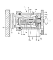
- FIG. 2 is a schematic cross-sectional view of a rear wheel system wheel brake mechanism provided in the vehicle brake device of the first embodiment.
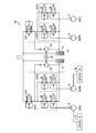
- FIG. 3 is a configuration diagram illustrating a schematic configuration of the hydraulic brake device and the electric brake device according to the first embodiment.
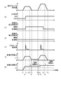
- FIG. 4 is a timing chart showing the operation of each component when the brake hold function is executed in the vehicle brake device of the first embodiment.
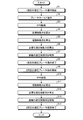
- FIG. 5 is a flowchart illustrating a process executed by the brake control device according to the first embodiment.
- FIG. 1 is a schematic diagram illustrating an overall outline of a vehicle brake device according to a first embodiment.
- FIG. 2 is a schematic cross-sectional view of a rear wheel system wheel brake mechanism provided in the vehicle brake device of the first embodiment.
- a vehicle brake device includes a service brake 1 that generates a service brake force (a hydraulic braking force) based on a treading force of a driver (driver), and a vehicle brake device that is used when the vehicle is parked. EPB2 for restricting movement.
- a service brake force a hydraulic braking force
- EPB2 for restricting movement.
- the service brake 1 generates a brake fluid pressure based on depression of the brake pedal 3 by a driver, and generates a service brake force based on the brake fluid pressure (hereinafter, also referred to as a “hydraulic brake device”). )). More specifically, the service brake 1 boosts the pedaling force according to the depression of the brake pedal 3 by the driver with the booster 4, and then applies the brake fluid pressure according to the boosted pedaling force to the master cylinder (hereinafter referred to as the master cylinder). , M / C). Then, a service brake force is generated by transmitting the brake fluid pressure to a wheel cylinder (hereinafter, referred to as W / C) 6 provided in a wheel brake mechanism of each wheel.
- W / C wheel cylinder
- an actuator 7 for controlling brake fluid pressure is provided between the M / C 5 and the W / C 6.
- the actuator 7 performs various controls (for example, anti-skid control and the like) for adjusting the service brake force generated by the service brake 1 and improving the safety of the vehicle.
- ESC-ECU 8 controls the service brake force.
- the ESC-ECU 8 outputs a control current for controlling various control valves and a pump driving motor provided in the actuator 7, thereby controlling a hydraulic circuit provided in the actuator 7 and transmitting it to the W / C 6.
- the actuator 7 controls, for each wheel, a pressure increase control that controls the application of the brake fluid pressure generated in the M / C 5 or the brake fluid pressure generated by driving the pump to the W / C 6.
- a valve and a pressure reduction control valve that reduces the W / C pressure by supplying the brake fluid in each W / C 6 to the reservoir are provided so that the W / C pressure can be increased, maintained, and reduced.
- the actuator 7 can realize an automatic pressurizing function of the service brake 1, and automatically applies the W / C 6 based on the driving of the pump and the control of various control valves even when there is no brake operation. Can be pressed. Details of the hydraulic brake device including the actuator 7 will be described later with reference to FIG.
- the EPB 2 generates an electric parking brake force (hereinafter, also referred to as “electric braking force” or “electric braking force”) by driving the wheel brake mechanism by the EPB motor 10. It has an EPB-ECU 9 (control unit) for controlling driving.
- the EPB-ECU 9 and the ESC-ECU 8 transmit and receive information by, for example, CAN (Controller Area Network) communication.
- the wheel brake mechanism is a mechanical structure that generates a braking force in the vehicle brake device of the first embodiment.
- the front wheel system wheel brake mechanism is configured to generate a service brake force by operating the service brake 1. ing.
- the wheel brake mechanism of the rear wheel system has a common structure that generates a braking force for both the operation of the service brake 1 and the operation of the EPB 2.
- the front wheel brake mechanism is a conventionally used wheel brake mechanism which eliminates the mechanism for generating an electric brake force based on the operation of the EPB2 with respect to the rear wheel brake mechanism. The description is omitted here, and the rear wheel system wheel brake mechanism will be described below.
- the wheel brake mechanism rotates the EPB motor 10 directly fixed to the body 14 of the W / C 6 for pressing the brake pad 11 in the caliper 13 shown in FIG. 1 as shown in FIG.
- the spur gear 15 provided on the drive shaft 10a of the EPB motor 10 is rotated.
- the brake pad 11 is moved, and the electric brake force by the EPB 2 is generated.
- the W / C 6 can generate a W / C pressure in the hollow portion 14a that is the brake fluid storage chamber by introducing the brake fluid pressure into the hollow portion 14a of the cylindrical body 14 through the passage 14b.
- the rotary shaft 17, the propulsion shaft 18, the piston 19 and the like are provided in the hollow portion 14 a.
- One end of the rotation shaft 17 is connected to the spur gear 16 through an insertion hole 14c formed in the body 14, and when the spur gear 16 is rotated, the rotation shaft 17 is rotated with the rotation of the spur gear 16.
- a male screw groove 17 a is formed on the outer peripheral surface of the rotating shaft 17.
- the other end of the rotating shaft 17 is supported by being inserted into the insertion hole 14c.
- the insertion hole 14c is provided with a bearing 21 together with the O-ring 20, so that the O-ring 20 prevents the brake fluid from leaking through between the rotating shaft 17 and the inner wall surface of the insertion hole 14c.
- the other end of the rotating shaft 17 is supported by the bearing 21 while being rotated.
- the propulsion shaft 18 is formed of a nut made of a hollow cylindrical member, and has a female screw groove 18a screwed with the male screw groove 17a of the rotating shaft 17 on the inner wall surface.
- the propulsion shaft 18 is formed, for example, in a cylindrical or polygonal shape having a key for preventing rotation, so that the propulsion shaft 18 can be rotated about the rotation center of the rotation shaft 17 even if the rotation shaft 17 rotates. There is no structure. Therefore, when the rotary shaft 17 is rotated, the rotational force of the rotary shaft 17 is reduced to a force for moving the propulsion shaft 18 in the axial direction of the rotary shaft 17 due to the engagement between the male screw groove 17a and the female screw groove 18a. Convert.
- the propulsion shaft 18 stops at the same position due to the frictional force generated by the engagement between the male screw groove 17a and the female screw groove 18a. If the drive of the EPB motor 10 is stopped when it becomes, the propulsion shaft 18 is held at that position, and the self-locking (hereinafter simply referred to as “locking”) can be performed while holding the desired electric braking force. I have.
- the piston 19 is arranged so as to surround the outer periphery of the propulsion shaft 18, and is formed of a bottomed cylindrical member or a polygonal cylindrical member, and the outer peripheral surface is in contact with the inner wall surface of the hollow portion 14 a formed in the body 14.
- a seal member 22 is provided on the inner wall surface of the body 14 to apply a W / C pressure to the end surface of the piston 19 so that the brake fluid does not leak between the outer peripheral surface of the piston 19 and the inner wall surface of the body 14. It has been.
- the seal member 22 is used to generate a reaction force for pulling back the piston 19 during release control after lock control.
- the seal member 22 is provided, basically, even if the brake pad 11 and the piston 19 are pushed by the brake disc 12 that is inclined during turning within a range that does not exceed the elastic deformation amount of the seal member 22, they are braked. By pushing back to the disc 12 side, the space between the brake disc 12 and the brake pad 11 can be maintained with a predetermined clearance.
- the propulsion shaft 18 When the propulsion shaft 18 is provided with a key for preventing rotation so that the piston 19 is not rotated about the rotation center of the rotation shaft 17 even when the rotation shaft 17 rotates, the key is When a sliding key groove is provided, and the propulsion shaft 18 has a polygonal column shape, the propulsion shaft 18 has a corresponding polygonal cylindrical shape.
- the brake pad 11 is disposed at the tip of the piston 19, and moves the brake pad 11 in the left-right direction on the drawing with the movement of the piston 19.
- the piston 19 is movable to the left in the drawing with the movement of the propulsion shaft 18, and is attached to an end of the piston 19 (an end opposite to the end on which the brake pad 11 is arranged).
- the W / C pressure By applying the W / C pressure, it is configured to be able to move leftward on the paper independently of the propulsion shaft 18.
- the piston 19 is moved leftward on the paper on the basis of the W / C pressure generated by the service brake 1, so that the brake pad 11 brakes. It is pressed by the disk 12 to generate a service brake force.
- the spur gear 15 is rotated by driving the EPB motor 10, and the spur gear 16 and the rotating shaft 17 are rotated accordingly.
- the propulsion shaft 18 is moved toward the brake disk 12 (to the left in the drawing) based on the engagement of 18a. Accordingly, the tip of the propulsion shaft 18 comes into contact with the bottom surface of the piston 19 and presses the piston 19, and the piston 19 is also moved in the same direction. Generate. Therefore, it is possible to use a common wheel brake mechanism that generates a braking force for both the operation of the service brake 1 and the operation of the EPB 2.
- the front-rear G sensor 25 detects a G (acceleration) in the front-rear direction (traveling direction) of the vehicle, and transmits a detection signal to the EPB-ECU 9.
- M / C pressure sensor 26 detects the M / C pressure at M / C 5 and sends a detection signal to EPB-ECU 9.
- the temperature sensor 28 detects the temperature of the wheel brake mechanism (for example, a brake disk) and transmits a detection signal to the EPB-ECU 9.
- the wheel speed sensor 29 detects the rotation speed of each wheel and transmits a detection signal to the EPB-ECU 9. It should be noted that the wheel speed sensors 29 are actually provided one by one corresponding to each wheel, but detailed illustration and description are omitted here.
- the EPB-ECU 9 is constituted by a well-known microcomputer including a CPU (Central Processing Unit), a ROM (Read Only Memory), a RAM (Random Access Memory), an I / O, and the like, according to a program stored in the ROM or the like.
- the parking brake control is performed by controlling the rotation of the EPB motor 10.
- the EPB-ECU 9 inputs, for example, a signal corresponding to the operation state of an operation switch (switch) 23 provided on an instrument panel (not shown) in the vehicle compartment, and outputs an EPB motor 10 according to the operation state of the operation switch 23. Drive. Further, the EPB-ECU 9 executes lock control, release control, and the like based on the detected current value of the EPB motor 10. And that the wheels are in a release state (EPB release state) by release control or by release control. Then, the EPB-ECU 9 outputs a signal for causing the display lamp 24 provided on the instrument panel to perform various displays.
- the vehicle brake device configured as described above basically performs an operation of generating a braking force on the vehicle by generating a service braking force by the service brake 1 during traveling of the vehicle. Further, when the vehicle is stopped by the service brake 1, the driver presses the operation SW 23 to activate the EPB 2 to generate an electric braking force, thereby maintaining the stopped state, and thereafter releasing the electric braking force. Is performed. That is, as the operation of the service brake 1, when the driver operates the brake pedal 3 during traveling of the vehicle, the brake fluid pressure generated in the M / C 5 is transmitted to the W / C 6 to generate a service brake force.
- the operation of the EPB 2 includes moving the piston 19 by driving the EPB motor 10, and pressing the brake pad 11 against the brake disc 12 to generate an electric braking force to lock the wheels, Is released from the brake disc 12 to release the electric braking force and release the wheels.
- the electric brake force is generated or released by lock / release control.
- the EPB 2 is operated by rotating the EPB motor 10 forward, and the EPB motor 10 is stopped at a position where the desired electric braking force can be generated by the EPB 2, and this state is maintained. Thereby, a desired electric braking force is generated.
- the EPB 2 is operated by rotating the EPB motor 10 in the reverse direction, and the electric braking force generated by the EPB 2 is released.
- FIG. 3 is a configuration diagram showing a schematic configuration of the hydraulic brake device and the electric brake device of the first embodiment.
- the vehicle brake device according to the first embodiment is configured to be able to apply a braking force (friction braking torque) to four wheels 50RL, 50RR, 50FR, and 50FL.
- the apparatus includes an apparatus 60 and an EPB 2 (FIG. 1) including an EPB motor 10 configured to apply a braking force to the two wheels 50RL and 50RR.
- the hydraulic brake device 60 includes four wheel cylinders 6, pressure adjusters 34RL, 34RR, 34FR, and 34FL, and a recirculation mechanism 37.
- Each of the four wheel cylinders 6 is a mechanism that applies a braking force to the wheels 50RL, 50RR, 50FR, and 50FL by pressing the brake pad 11 (FIG. 1).
- Each of the pressure adjusting units 34RL, 34RR, 34FR, and 34FL is a mechanism that adjusts the hydraulic pressure applied to the corresponding wheel cylinder 6.
- the recirculation mechanism 37 is a mechanism for returning fluid (working fluid) as a medium for generating hydraulic pressure to the upstream side.
- the differential pressure control valves 33R and 33F open and close based on the control of the ESC-ECU 8 (see FIG. 1).
- the pressure adjusting units 34RL, 34RR, 34FR, and 34FL have solenoid valves 35 and 36, respectively, that can be electrically switched between an open state and a closed state.
- the solenoid valves 35 and 36 are provided between the differential pressure control valve 33 and the reservoir 41.
- the solenoid valve 35 is connected to the differential pressure control valves 33R and 33F, and the solenoid valve 36 is connected to the reservoir 41.
- the solenoid valves 35 and 36 open and close based on the control of the ESC-ECU 8 to increase, maintain, or reduce the pressure generated in the wheel cylinder 6.
- the reflux mechanism 37 includes a reservoir 41 and a pump 39, and a pump motor 40 that rotates the front and rear pumps 39 to transport fluid to the upstream side.
- One reservoir 41 and one pump 39 are provided corresponding to the combination of the pressure adjustment units 34RL and 34RR and the combination of the pressure adjustment units 34FR and 34FL.
- an EPB motor 10 that is driven based on the control of the EPB-ECU 9 (FIG. 2) is connected to each of the two wheel cylinders 6 on the rear side.
- the brake pads 11 (FIG. 2) of the two rear wheel cylinders 6 are pressurized in response to the driving of the EPB motor 10, so that the rear wheels 50RL and 50RR are electrically driven. A braking force is applied. Therefore, in the first embodiment, the two rear wheel cylinders 6 and the two EPB motors 10 connected to the two wheel cylinders 6 are different from the hydraulic braking force of the hydraulic braking device 60 in the parking control. It functions as EPB2 that can generate power.
- the ESC-ECU 8 and the EPB-ECU 9 press the brake pads 11 (braking members) with respect to the front and rear wheels of the vehicle toward the brake discs 12 (braking members) that rotate integrally with the wheels.
- the hydraulic brake device that generates the hydraulic braking force, and the electric brake wheel of one of the front wheel and the rear wheel And an electric brake device for generating an electric braking force.
- the ESC-ECU 8 executes the following brake hold control.
- the EPB-ECU 9 drives the EPB 2 to move the propulsion shaft 18 to the brake disk 12 side to contact the piston 19 with respect to the rear wheels (electrically braked wheels), and to maintain the stopped state of the vehicle. Calculate the target braking force. Further, the EPB-ECU 9 subtracts the electric braking force generated by the EPB 2 when the hydraulic pressure is lost from the target braking force, and calculates the required hydraulic braking force on the front wheels (non-electrically-driven braking wheels). The ESC-ECU 8 controls the front wheel differential pressure control valve 33F (FIG. 3) of the hydraulic brake device 60 so that the front wheels generate necessary hydraulic braking force.
- the ESC-ECU 8 sets the hydraulic braking device so that the front wheels do not generate the hydraulic braking force.
- the 60 front wheel differential pressure control valves 33F are controlled.
- FIG. 4 is a timing chart illustrating the operation of each component when the brake hold function is executed in the vehicle brake device of the first embodiment.
- the horizontal axis represents time.
- the vertical axis represents the hydraulic brake operation amount (the amount of depression of the brake pedal 3).
- the vertical axis indicates the presence / absence (ON / OFF) of a brake hold (BH) instruction (BH start operation by the operation SW 23).
- the vertical axis represents the energized state (energized / non-energized) of the front wheel differential pressure control valve 33F.
- the vertical axis indicates the energized state (energized / non-energized) of the rear wheel differential pressure control valve 33R.
- the vertical axis represents the current value (current detection value) of the EPB motor 10.
- the vertical axis represents the braking force of the front wheels.
- the vertical axis represents the braking force of the rear wheel.
- the driver While the vehicle is stopped, as shown in FIG. 4A, the driver performs the first hydraulic brake operation from time t1 to time t7, and then performs the second hydraulic brake operation from time t8 to time t14 stronger than the first time. It is assumed that the hydraulic brake operation has been performed. Further, as shown in FIG. 4B, it is assumed that the driver issues a BH instruction (BH start operation by the operation SW 23) at time t3, and thereafter, the ON state of the BH instruction continues.
- BH instruction BH start operation by the operation SW 23
- the EPB-ECU 9 drives the EPB 2 to operate the EPB motor 10 for the rear wheels to move the propulsion shaft 18 (FIG. 2) toward the brake disk 12 and abut on the piston 19 (FIG. 4 ( e) times t3 to t4).
- the EPB-ECU 9 drives the EPB 2 to operate the EPB motor 10 for the rear wheels to move the propulsion shaft 18 (FIG. 2) toward the brake disk 12 and abut on the piston 19 (FIG. 4 ( e) times t3 to t4).
- the EPB-ECU 9 calculates a target braking force for maintaining the vehicle in a stopped state (for example, it is determined based on a road gradient or the like calculated from values detected by the front and rear G sensors). Further, the EPB-ECU 9 subtracts the electric braking force generated by the EPB 2 when the hydraulic pressure is lost from the target braking force, and calculates the required hydraulic braking force on the front wheels.
- the ESC-ECU 8 controls the front wheel differential pressure control valve 33F (FIG. 3) of the hydraulic brake device 60 so that the necessary hydraulic braking force is generated by the front wheels.
- the necessary hydraulic braking force is maintained (FIG. 4 (f)).
- the ESC-ECU 8 and the EPB-ECU 9 perform the brake hold control again. Run from the beginning. That is, first, the EPB-ECU 9 drives the EPB 2 to operate the EPB motor 10 for the rear wheels to move the propulsion shaft 18 (FIG. 2) to the brake disk 12 side to contact the piston 19 (FIG. 4).
- E Times t11 to t12).
- the electric braking force after time t13 can be made larger than the electric braking force from time t5 to time t10 (FIG. 4 (g)).
- the EPB-ECU 9 calculates the required hydraulic braking force on the front wheels by subtracting the electric braking force generated by the EPB 2 when the hydraulic pressure is lost from the target braking force. At this time, if the calculated necessary hydraulic braking force is equal to or less than zero, the ESC-ECU 8 controls the front wheel differential pressure control valve 33F of the hydraulic braking device 60 so that the front wheel does not generate the hydraulic braking force. Accordingly, as shown in FIG. 4F, the braking force of the front wheels starts to decrease from time t13 and becomes zero at time t14. However, after time t14, even if the braking force on the front wheels is zero (FIG. 4 (f)), the braking force on the rear wheels is large (FIG. 4 (g)), and the braking force for maintaining the stopped state of the entire vehicle is Is secured.
- FIG. 5 is a flowchart illustrating a process executed by the brake control device according to the first embodiment.
- step S1 in FIG. 5 time t1 in FIG. 4A.
- step S2 in FIG. 5 time t3 in FIG. 4B
- the EPB-ECU 9 sets the rear wheel.
- the EPB 2 is driven to operate the EPB motor 10 to move the propulsion shaft 18 toward the brake disk 12 and abut on the piston 19 (step S3 in FIG. 5: time t3 to t4 in FIG. 4E).
- the EPB-ECU 9 calculates a target braking force for maintaining the vehicle in a stopped state (Step S4 in FIG. 5).
- the EPB-ECU 9 calculates an electric braking force (for example, the same magnitude as the original hydraulic braking force) generated by the EPB 2 when the hydraulic pressure is lost (Step S5 in FIG. 5).
- the EPB-ECU 9 calculates the required hydraulic braking force on the front wheels by subtracting the electric braking force calculated in step S5 from the target braking force calculated in step S4 (step S6 in FIG. 5).
- the ESC-ECU 8 controls the front wheel differential pressure control valve 33F (FIG. 3) of the hydraulic brake device 60 so that the front wheels generate the necessary hydraulic braking force calculated in step S6 (step in FIG. 5). S7).
- step S8 in FIG. 5 time t7 in FIG. 4A.
- the driver ends the first hydraulic brake operation (step S8 in FIG. 5: time t7 in FIG. 4A).
- the braking force of the rear wheels is maintained even after time t5 when the driver starts releasing the hydraulic brake operation.
- the braking force of the front wheels is maintained at the required hydraulic braking force.
- step S9 in FIG. 5 time t9 in FIG. 4A.
- the EPB-ECU 9 drives the EPB 2 to operate the EPB motor 10 for the rear wheels to operate the propulsion shaft 18. It is moved to the brake disk 12 side and brought into contact with the piston 19 (step S10 in FIG. 5: times t11 to t12 in FIG. 4E).
- the EPB-ECU 9 calculates an electric braking force (for example, the same magnitude as the original hydraulic braking force) generated by the EPB 2 when the hydraulic pressure is lost (Step S11 in FIG. 5).
- the EPB-ECU 9 calculates the required hydraulic braking force on the front wheels by subtracting the electric braking force calculated in Step S11 from the target braking force calculated in Step S4 (Step S12 in FIG. 5).
- the ESC-ECU 8 controls the front wheel differential pressure control valve 33F (FIG. 3) of the hydraulic brake device 60 so that the front wheel generates the necessary hydraulic braking force calculated in step S12 (step in FIG. 5). S13).
- step S14 in FIG. 5 time t14 in FIG. 4A.
- the driver ends the second hydraulic brake operation (step S14 in FIG. 5: time t14 in FIG. 4A).
- step S14 in FIG. 5 time t14 in FIG. 4A.
- the braking force of the rear wheels is maintained even after time t13 when the driver starts releasing the hydraulic brake operation.
- step S14 in FIG. 5 time t14 in FIG. 4A.
- the brake hold function can be realized with low power consumption by using the EPB2. That is, for example, as shown in FIG. 4C, the energization of the differential pressure control valve 33F of the front wheel can be performed from time t3 to time t12.
- the front-wheel differential pressure control valve must be energized while the BH instruction is ON (FIG. 4B), and the power consumption is large.
- L2 shown in FIG. 4 (g) is a target value of the braking force of the rear wheels in the first method.
- the EPB motor 10 is only driven from the time t3 to the time t4, and even after the time t5 when the driver starts to relax the hydraulic brake operation, the braking force of the rear wheel larger than L2. Can be maintained and efficient. Further, by simply driving the EPB motor 10 from time t11 to time t12, even after time t13 when the driver starts to loosen the hydraulic brake operation, it is possible to maintain a greater braking force on the rear wheel, which is efficient.
- L1 shown in FIG. 4 (f) is a target value of the braking force of the front wheels in the first method.
- the braking force of the front wheels (FIG. 4 (f)) is equal to the braking force of the rear wheels that can be maintained larger than L2 (FIG. 4 (g)).
- the differential pressure control valve even if the differential pressure control valve is continuously energized in order to maintain the stop state, fluid may pass through the differential pressure control valve little by little for structural reasons. In some cases, the braking force is reduced due to a slight decrease in the fluid pressure, and it may not be possible to maintain a stopped state for a long time. On the other hand, according to the brake control device of the first embodiment, such a decrease does not occur in the electric braking force by the EPB2, so that the vehicle can be kept stopped even for a long time.
- the EPB-ECU 9 controls the EPB 2 for the rear wheels so that the electric braking force becomes the target braking force. I do.
- the rear wheels are the electric brake wheels, but the invention is not limited thereto, and the front wheels may be the electric brake wheels.
- the hydraulic circuit is a so-called front-rear pipe (a pipe configuration in which the output from the M / C 5 is divided into two systems of two front wheels and two rear wheels) as shown in FIG. 3, but is not limited thereto.
- the circuit may be a so-called X pipe (a pipe configuration in which the output from the M / C 5 is divided into two systems of front and rear wheels on a diagonal line).
- X pipe a pipe configuration in which the output from the M / C 5 is divided into two systems of front and rear wheels on a diagonal line.
- the differential pressure control valve of the front wheel is not energized after time t12.
- the two differential pressure control valves can be de-energized during the execution of the brake hold function, so that the power consumption can be reduced.
- the present invention can also be applied to the execution of a brake hold function in an automatic driving vehicle.
- the brake hold control may be executed when the control unit determines that the brake hold control is necessary irrespective of the driver's intention or operation.
- the mode in which the electric brake device is operated and the brake hold control is executed in a situation where the hydraulic braking force is generated by operating the brake pedal has been described.
- the brake hold control may be performed in a state where the hydraulic pressure is automatically generated by the control unit while the brake pedal is not operated.
Landscapes
- Engineering & Computer Science (AREA)
- Transportation (AREA)
- Mechanical Engineering (AREA)
- Regulating Braking Force (AREA)
- Braking Systems And Boosters (AREA)
Abstract
実施形態によるブレーキ制御装置は、前輪、および、後輪の一方の電動制動車輪について、電動ブレーキ装置を駆動して推進軸を被制動部材側に移動させてピストンに当接させるとともに、車両の停車状態を維持するための目標制動力を算出し、目標制動力から、液圧が無くなった場合に電動ブレーキ装置によって発生する電動制動力を減算して、前輪、および、後輪の他方の非電動制動車輪で必要な液圧制動力を算出し、非電動制動車輪が必要な液圧制動力を発生するように液圧ブレーキ装置の非電動制動車輪の差圧制御弁を制御するブレーキホールド制御を実行する。
Description
本発明は、ブレーキ制御装置に関する。
近年、乗用車等の車両において、運転者によるブレーキペダルの操作によって停車した際に自動的にブレーキ力を保持するブレーキホールド機能が多く採用されている。このブレーキホールド機能は、特に坂路で車両を停車させる場合に便利である。
これまで、ブレーキホールド機能を実現するには、大別して2つの方法があった。第1の方法は、運転者によってブレーキペダルが操作されて車輪に液圧がかけられているときに、液圧回路における常開の差圧制御弁に通電して閉状態とすることによって、ブレーキペダルの操作が無くなった後もその液圧を保持する方法である。第2の方法は、運転者によってブレーキペダルが操作されて車輪に液圧がかけられているときに、併せてEPB(Electric Parking Brake)によって停車状態の維持に必要な電動ブレーキ力を算出して発生させる方法である。
しかしながら、第1の方法では、停車状態を維持する間は差圧制御弁に通電し続けなければならず、消費電力が大きくなってしまうという問題があった。また、第2の方法では、液圧とは別にEPBで独立して停車状態の維持に必要な電動ブレーキ力を算出して発生させるため、余分な制動力を発生させてしまい、したがって、余分な消費電力を発生させてしまうという問題があった。
そこで、本発明の課題の一つは、EPBを用いて少ない消費電力でブレーキホールド機能を実現することが可能なブレーキ制御装置を提供することである。
本発明によるブレーキ制御装置は、例えば、車両の前輪、および、後輪について、車輪と一体に回転する被制動部材に向けて、液圧によって制動部材を押圧して、液圧制動力を発生させる液圧ブレーキ装置と、前記前輪、および、前記後輪の一方の電動制動車輪について、前記被制動部材に向けて、モータを駆動することによって前記制動部材を押圧して、電動制動力を発生させる電動ブレーキ装置と、を備える車両に適用されるブレーキ制御装置である。ブレーキ制御装置は、前記液圧ブレーキ装置により発生している前記液圧制動力によって前記車両の停車状態が維持されている状況で、前記停車状態を維持するブレーキホールド制御の実行が許可されている場合に、前記電動制動車輪について、前記電動ブレーキ装置を駆動して推進軸を前記被制動部材側に移動させてピストンに当接させるとともに、前記車両の停車状態を維持するための目標制動力を算出し、前記目標制動力から、液圧が無くなった場合に前記電動ブレーキ装置によって発生する前記電動制動力を減算して、前記前輪、および、前記後輪の他方の非電動制動車輪で必要な液圧制動力を算出し、前記非電動制動車輪が前記必要な液圧制動力を発生するように前記液圧ブレーキ装置の前記非電動制動車輪の差圧制御弁を制御する前記ブレーキホールド制御を実行する制御部を備える。
以下、本発明の例示的な実施形態(第1実施形態、第2実施形態)が開示される。以下に示される実施形態の構成、ならびに当該構成によってもたらされる作用および結果(効果)は、例である。本発明は、以下の実施形態に開示される構成以外によっても実現可能である。また、本発明によれば、以下の構成によって得られる種々の効果(派生的な効果も含む)のうち少なくとも一つを得ることが可能である。
(第1実施形態)
第1実施形態では、後輪系にディスクブレーキタイプのEPBを適用している車両用ブレーキ装置を例に挙げて説明する。図1は、第1実施形態の車両用ブレーキ装置の全体概要を示す模式図である。図2は、第1実施形態の車両用ブレーキ装置に備えられる後輪系の車輪ブレーキ機構の断面模式図である。
第1実施形態では、後輪系にディスクブレーキタイプのEPBを適用している車両用ブレーキ装置を例に挙げて説明する。図1は、第1実施形態の車両用ブレーキ装置の全体概要を示す模式図である。図2は、第1実施形態の車両用ブレーキ装置に備えられる後輪系の車輪ブレーキ機構の断面模式図である。
図1に示すように、第1実施形態の車両用ブレーキ装置は、ドライバ(運転者)の踏力に基いてサービスブレーキ力(液圧制動力)を発生させるサービスブレーキ1と、駐車時などに車両の移動を規制するためのEPB2と、を備えている。
サービスブレーキ1は、ドライバによるブレーキペダル3の踏み込みに基いてブレーキ液圧を発生させ、このブレーキ液圧に基いてサービスブレーキ力を発生させる液圧ブレーキ機構(以下、「液圧ブレーキ装置」ともいう。)である。具体的には、サービスブレーキ1は、ドライバによるブレーキペダル3の踏み込みに応じた踏力を倍力装置4にて倍力したのち、この倍力された踏力に応じたブレーキ液圧をマスタシリンダ(以下、M/Cという。)5内に発生させる。そして、このブレーキ液圧を各車輪の車輪ブレーキ機構に備えられたホイールシリンダ(以下、W/Cという。)6に伝えることでサービスブレーキ力を発生させる。また、M/C5とW/C6との間にブレーキ液圧制御用のアクチュエータ7が備えられている。アクチュエータ7は、サービスブレーキ1により発生させるサービスブレーキ力を調整し、車両の安全性を向上させるための各種制御(例えば、アンチスキッド制御等)を行う。
アクチュエータ7を用いた各種制御は、サービスブレーキ力を制御するESC(Electronic Stability Control)-ECU8にて実行される。例えば、アクチュエータ7に備えられる各種制御弁やポンプ駆動用のモータを制御するための制御電流をESC-ECU8が出力することにより、アクチュエータ7に備えられる液圧回路を制御し、W/C6に伝えられるW/C圧を制御する。これにより、車輪スリップの回避などを行い、車両の安全性を向上させる。例えば、アクチュエータ7は、各車輪毎に、W/C6に対してM/C5内に発生させられたブレーキ液圧もしくはポンプ駆動により発生させられたブレーキ液圧が加えられることを制御する増圧制御弁や、各W/C6内のブレーキ液をリザーバに供給することでW/C圧を減少させる減圧制御弁等を備えており、W/C圧を増圧・保持・減圧制御できる構成とされている。また、アクチュエータ7は、サービスブレーキ1の自動加圧機能を実現可能にしており、ポンプ駆動および各種制御弁の制御に基いて、ブレーキ操作がない状態であっても自動的にW/C6を加圧できる。アクチュエータ7を含む液圧ブレーキ装置の詳細については、図3を参照して後述する。
一方、EPB2は、EPBモータ10によって車輪ブレーキ機構を駆動させることで電動駐車ブレーキ力(以下、「電動制動力」、「電動ブレーキ力」ともいう。)を発生させるものであり、EPBモータ10の駆動を制御するEPB-ECU9(制御部)を有して構成されている。なお、EPB-ECU9とESC-ECU8は、例えばCAN(Controller Area Network)通信によって情報の送受信を行う。
車輪ブレーキ機構は、第1実施形態の車両用ブレーキ装置においてブレーキ力を発生させる機械的構造であり、まず、前輪系の車輪ブレーキ機構はサービスブレーキ1の操作によってサービスブレーキ力を発生させる構造とされている。一方、後輪系の車輪ブレーキ機構は、サービスブレーキ1の操作とEPB2の操作の双方に対してブレーキ力を発生させる共用の構造とされている。前輪系の車輪ブレーキ機構は、後輪系の車輪ブレーキ機構に対して、EPB2の操作に基いて電動ブレーキ力を発生させる機構をなくした従来から一般的に用いられている車輪ブレーキ機構であるため、ここでは説明を省略し、以下では後輪系の車輪ブレーキ機構について説明する。
後輪系の車輪ブレーキ機構では、サービスブレーキ1を作動させたときだけでなくEPB2を作動させたときにも、図2に示す摩擦材であるブレーキパッド11を押圧し、ブレーキパッド11によって被摩擦材であるブレーキディスク12(12RL、12RR、12FR、12FL)を挟み込むことにより、ブレーキパッド11とブレーキディスク12との間に摩擦力を発生させ、ブレーキ力を発生させる。
具体的には、車輪ブレーキ機構は、図1に示すキャリパ13内において、図2に示すようにブレーキパッド11を押圧するためのW/C6のボディ14に直接固定されているEPBモータ10を回転させることにより、EPBモータ10の駆動軸10aに備えられた平歯車15を回転させる。そして、平歯車15に噛合わされた平歯車16にEPBモータ10の回転力(出力)を伝えることによりブレーキパッド11を移動させ、EPB2による電動ブレーキ力を発生させる。
キャリパ13内には、W/C6およびブレーキパッド11に加えて、ブレーキパッド11に挟み込まれるようにしてブレーキディスク12の端面の一部が収容されている。W/C6は、シリンダ状のボディ14の中空部14a内に通路14bを通じてブレーキ液圧を導入することで、ブレーキ液収容室である中空部14a内にW/C圧を発生させられるようになっており、中空部14a内に回転軸17、推進軸18、ピストン19などを備えて構成されている。
回転軸17は、一端がボディ14に形成された挿入孔14cを通じて平歯車16に連結され、平歯車16が回動させられると、平歯車16の回動に伴って回動させられる。この回転軸17における平歯車16と連結された端部とは反対側の端部において、回転軸17の外周面には雄ネジ溝17aが形成されている。一方、回転軸17の他端は、挿入孔14cに挿入されることで軸支されている。具体的には、挿入孔14cには、Oリング20と共に軸受け21が備えられており、Oリング20にて回転軸17と挿入孔14cの内壁面との間を通じてブレーキ液が漏れ出さないようにされながら、軸受け21により回転軸17の他端を軸支持している。
推進軸18は、中空状の筒部材からなるナットにて構成され、内壁面に回転軸17の雄ネジ溝17aと螺合する雌ネジ溝18aが形成されている。この推進軸18は、例えば回転防止用のキーを備えた円柱状もしくは多角柱状に構成されることで、回転軸17が回動しても回転軸17の回動中心を中心として回動させられない構造になっている。このため、回転軸17が回動させられると、雄ネジ溝17aと雌ネジ溝18aとの噛合いにより、回転軸17の回転力を回転軸17の軸方向に推進軸18を移動させる力に変換する。推進軸18は、EPBモータ10の駆動が停止されると、雄ネジ溝17aと雌ネジ溝18aとの噛合いによる摩擦力により同じ位置で止まるようになっており、目標とする電動ブレーキ力になったときにEPBモータ10の駆動を停止すれば、推進軸18がその位置で保持され、所望の電動ブレーキ力を保持してセルフロック(以下、単に「ロック」という。)できるようになっている。
ピストン19は、推進軸18の外周を囲むように配置されるもので、有底の円筒部材もしくは多角筒部材にて構成され、外周面がボディ14に形成された中空部14aの内壁面と接するように配置されている。ピストン19の外周面とボディ14の内壁面との間のブレーキ液漏れが生じないように、ボディ14の内壁面にシール部材22が備えられ、ピストン19の端面にW/C圧を付与できる構造とされている。シール部材22は、ロック制御後のリリース制御時にピストン19を引き戻すための反力を発生させるために用いられる。このシール部材22を備えてあるため、基本的には旋回中に傾斜したブレーキディスク12によってブレーキパッド11およびピストン19がシール部材22の弾性変形量を超えない範囲で押し込まれても、それらをブレーキディスク12側に押し戻してブレーキディスク12とブレーキパッド11との間が所定のクリアランスで保持されるようにできる。
また、ピストン19は、回転軸17が回転しても回転軸17の回動中心を中心として回動させられないように、推進軸18に回転防止用のキーが備えられる場合にはそのキーが摺動するキー溝が備えられ、推進軸18が多角柱状とされる場合にはそれと対応する形状の多角筒状とされる。
このピストン19の先端にブレーキパッド11が配置され、ピストン19の移動に伴ってブレーキパッド11を紙面左右方向に移動させるようになっている。具体的には、ピストン19は、推進軸18の移動に伴って紙面左方向に移動可能で、かつ、ピストン19の端部(ブレーキパッド11が配置された端部と反対側の端部)にW/C圧が付与されることで推進軸18から独立して紙面左方向に移動可能な構成とされている。そして、推進軸18が通常リリースのときの待機位置であるリリース位置(EPBモータ10が回転させられる前の状態)のときに、中空部14a内のブレーキ液圧が付与されていない状態(W/C圧=0)であれば、後述するシール部材22の弾性力によりピストン19が紙面右方向に移動させられ、ブレーキパッド11をブレーキディスク12から離間させられるようになっている。また、EPBモータ10が回転させられて推進軸18が初期位置から紙面左方向に移動させられているときには、W/C圧が0になっても、移動した推進軸18によってピストン19の紙面右方向への移動が規制され、ブレーキパッド11がその場所で保持される。
このように構成された車輪ブレーキ機構では、サービスブレーキ1が操作されると、それにより発生させられたW/C圧に基いてピストン19が紙面左方向に移動させられることでブレーキパッド11がブレーキディスク12に押圧され、サービスブレーキ力を発生させる。また、EPB2が操作されると、EPBモータ10が駆動されることで平歯車15が回転させられ、それに伴って平歯車16および回転軸17が回転させられるため、雄ネジ溝17aおよび雌ネジ溝18aの噛合いに基いて推進軸18がブレーキディスク12側(紙面左方向)に移動させられる。そして、それに伴って推進軸18の先端がピストン19の底面に当接してピストン19を押圧し、ピストン19も同方向に移動させられることでブレーキパッド11がブレーキディスク12に押圧され、電動ブレーキ力を発生させる。このため、サービスブレーキ1の操作とEPB2の操作の双方に対してブレーキ力を発生させる共用の車輪ブレーキ機構とすることが可能となる。
また、EPBモータ10の電流を検出する電流センサ(不図示)による電流検出値を確認することにより、EPB2による電動制動力の発生状態を確認したり、その電流検出値を認識したりすることができる。
前後Gセンサ25は、車両の前後方向(進行方向)のG(加速度)を検出し、検出信号をEPB-ECU9に送信する。
M/C圧センサ26は、M/C5におけるM/C圧を検出して、検出信号をEPB-ECU9に送信する。
温度センサ28は、車輪ブレーキ機構(例えばブレーキディスク)の温度を検出して、検出信号をEPB-ECU9に送信する。
車輪速センサ29は、各車輪の回転速度を検出し、検出信号をEPB-ECU9に送信する。なお、車輪速センサ29は、実際には各車輪に対応して1つずつ設けられるが、ここでは、詳細な図示や説明を省略する。
EPB-ECU9は、CPU(Central Processing Unit)、ROM(Read Only Memory)、RAM(Random Access Memory)、I/Oなどを備えた周知のマイクロコンピュータによって構成され、ROMなどに記憶されたプログラムにしたがってEPBモータ10の回転を制御することにより駐車ブレーキ制御を行うものである。
EPB-ECU9は、例えば車室内のインストルメントパネル(図示せず)に備えられた操作SW(スイッチ)23の操作状態に応じた信号等を入力し、操作SW23の操作状態に応じてEPBモータ10を駆動する。さらに、EPB-ECU9は、EPBモータ10の電流検出値に基いてロック制御やリリース制御などを実行するものであり、その制御状態に基いてロック制御中であることやロック制御によって車輪がロック状態であること、および、リリース制御中であることやリリース制御によって車輪がリリース状態(EPB解除状態)であることを認識する。そして、EPB-ECU9は、インストルメントパネルに備えられた表示ランプ24に対し、各種表示を行わせるための信号を出力する。
以上のように構成された車両用ブレーキ装置では、基本的には、車両走行時にサービスブレーキ1によってサービスブレーキ力を発生させることで車両に制動力を発生させるという動作を行う。また、サービスブレーキ1によって車両が停車した際に、ドライバが操作SW23を押下してEPB2を作動させて電動ブレーキ力を発生させることで停車状態を維持したり、その後に電動ブレーキ力を解除したりするという動作を行う。すなわち、サービスブレーキ1の動作としては、車両走行時にドライバによるブレーキペダル3の操作が行われると、M/C5に発生したブレーキ液圧がW/C6に伝えられることでサービスブレーキ力を発生させる。また、EPB2の動作としては、EPBモータ10を駆動することでピストン19を移動させ、ブレーキパッド11をブレーキディスク12に押し付けることで電動ブレーキ力を発生させて車輪をロック状態にしたり、ブレーキパッド11をブレーキディスク12から離すことで電動ブレーキ力を解除して車輪をリリース状態にしたりする。
具体的には、ロック・リリース制御により、電動ブレーキ力を発生させたり解除したりする。ロック制御では、EPBモータ10を正回転させることによりEPB2を作動させ、EPB2にて所望の電動ブレーキ力を発生させられる位置でEPBモータ10の回転を停止し、この状態を維持する。これにより、所望の電動ブレーキ力を発生させる。リリース制御では、EPBモータ10を逆回転させることによりEPB2を作動させ、EPB2にて発生させられている電動ブレーキ力を解除する。
図3は、第1実施形態の液圧ブレーキ装置と電動ブレーキ装置の概略的構成を示す構成図である。図3に示すように、第1実施形態による車両用ブレーキ装置は、4個の車輪50RL、50RR、50FRおよび50FLに制動力(摩擦制動トルク)を付与することが可能に構成された液圧ブレーキ装置60と、2個の車輪50RLおよび50RRに制動力を付与することが可能に構成された、EPBモータ10を含むEPB2(図1)を備える。
液圧ブレーキ装置60は、4つのホイールシリンダ6と、圧力調整部34RL、34RR、34FRおよび34FLと、還流機構37と、を備える。4つのホイールシリンダ6は、それぞれ、ブレーキパッド11(図1)を加圧して車輪50RL、50RR、50FR、および50FLに制動力を付与する機構である。圧力調整部34RL、34RR、34FRおよび34FLは、それぞれ、対応するホイールシリンダ6に与えられる液圧を調整する機構である。還流機構37は、液圧を発生させる媒体としてのフルード(作動流体)を上流側へ戻す機構である。差圧制御弁33R、33Fは、ESC-ECU8(図1参照)の制御に基いて開閉する。
圧力調整部34RL、34RR、34FRおよび34FLは、それぞれ、開状態と閉状態とを電気的に切り替え可能な電磁弁35および36を有している。電磁弁35および36は、差圧制御弁33とリザーバ41との間に設けられている。電磁弁35は、差圧制御弁33R、33Fに接続され、電磁弁36は、リザーバ41に接続されている。
電磁弁35および36は、ESC-ECU8の制御に基いて開閉することで、ホイールシリンダ6で発生する圧力を、昇圧したり、維持したり、減圧したりする。
還流機構37は、リザーバ41およびポンプ39と、フロント側およびリヤ側のポンプ39を回転してフルードを上流側に輸送するポンプモータ40と、を備える。リザーバ41およびポンプ39は、圧力調整部34RLおよび34RRの組み合わせと、圧力調整部34FRおよび34FLの組み合わせと、に対応してそれぞれ1つずつ設けられる。
ここで、第1実施形態では、リヤ側の2つのホイールシリンダ6の各々に、EPB-ECU9(図2)の制御に基いて駆動するEPBモータ10が接続されている。これにより、第1実施形態では、リヤ側の2つのホイールシリンダ6のブレーキパッド11(図2)がEPBモータ10の駆動に応じて加圧されることで、リヤ側の車輪50RLおよび50RRに電動制動力が付与される。したがって、第1実施形態では、リヤ側の2つのホイールシリンダ6と、これら2つのホイールシリンダ6に接続された2つのEPBモータ10が、液圧ブレーキ装置60による液圧制動力とは別個の駐車制動力を発生可能なEPB2として機能する。
ここで、ESC-ECU8とEPB-ECU9の制御の詳細について説明する。ESC-ECU8とEPB-ECU9は、車両の前輪、および、後輪について、車輪と一体に回転するブレーキディスク12(被制動部材)に向けて、液圧によってブレーキパッド11(制動部材)を押圧して、液圧制動力を発生させる液圧ブレーキ装置と、前輪、および、後輪の一方の電動制動車輪について、ブレーキディスク12に向けて、EPBモータ10を駆動することによってブレーキパッド11を押圧して、電動制動力を発生させる電動ブレーキ装置と、を備える車両に適用される。
そして、液圧ブレーキ装置60により発生している液圧制動力によって車両の停車状態が維持されている状況で、停車状態を維持するブレーキホールド制御の実行が許可されている場合に、ESC-ECU8とEPB-ECU9は、以下のブレーキホールド制御を実行する。
EPB-ECU9は、まず、後輪(電動制動車輪)について、EPB2を駆動して推進軸18をブレーキディスク12側に移動させてピストン19に当接させるとともに、車両の停車状態を維持するための目標制動力を算出する。また、EPB-ECU9は、目標制動力から、液圧が無くなった場合にEPB2によって発生する電動制動力を減算して、前輪(非電動制動車輪)で必要な液圧制動力を算出する。ESC-ECU8は、前輪が必要な液圧制動力を発生するように液圧ブレーキ装置60の前輪の差圧制御弁33F(図3)を制御する。
また、目標制動力から、液圧が無くなった場合にEPB2によって発生する電動制動力を減算した値がゼロ以下の場合、ESC-ECU8は、前輪が液圧制動力を発生しないように液圧ブレーキ装置60の前輪の差圧制御弁33Fを制御する。
また、ブレーキホールド制御の実行中に、液圧ブレーキ操作によって発生している液圧ブレーキ装置60による液圧制動力が増加した場合、ESC-ECU8とEPB-ECU9は、再度、ブレーキホールド制御を初めから実行する。
次に、図4を参照して、第1実施形態においてブレーキホールド機能を実行する場合の各構成の動作の様子について説明する。図4は、第1実施形態の車両用ブレーキ装置においてブレーキホールド機能を実行する場合の各構成の動作の様子を示すタイミングチャートである。図4(a)~図4(g)において、横軸は時間を表す。図4(a)において、縦軸は液圧ブレーキ操作量(ブレーキペダル3の踏み込み量)を表す。図4(b)において、縦軸はブレーキホールド(BH)指示(操作SW23によるBH開始操作)の有無(ON/OFF)を表す。図4(c)において、縦軸は前輪の差圧制御弁33Fの通電状態(通電/非通電)を表す。図4(d)において、縦軸は後輪の差圧制御弁33Rの通電状態(通電/非通電)を表す。図4(e)において、縦軸はEPBモータ10の電流値(電流検出値)を表す。図4(f)において、縦軸は前輪の制動力を表す。図4(g)において、縦軸は後輪の制動力を表す。
車両の停車中に、図4(a)に示すように、ドライバが、時刻t1から時刻t7まで1回目の液圧ブレーキ操作を行い、その後、時刻t8から時刻t14まで1回目よりも強く2回目の液圧ブレーキ操作を行ったものとする。また、図4(b)に示すように、ドライバが時刻t3にBH指示(操作SW23によるBH開始操作)を行い、その後、BH指示のON状態が継続するものとする。
その場合、EPB-ECU9は、後輪について、EPB2を駆動してEPBモータ10を動作させて推進軸18(図2)をブレーキディスク12側に移動させてピストン19に当接させる(図4(e)の時刻t3~t4)。そうすることで、後輪について、その後に液圧が減少しても(図4(a)の時刻t5以降)、それまでの液圧制動力とほぼ同等の電動制動力を発生させることができる(図4(g))。
次に、EPB-ECU9は、車両の停車状態を維持するための目標制動力を算出(例えば前後Gセンサによる検出値から算出した道路勾配等に基いて決定)する。また、EPB-ECU9は、目標制動力から、液圧が無くなった場合にEPB2によって発生する電動制動力を減算して、前輪で必要な液圧制動力を算出する。
そして、ESC-ECU8は、その必要な液圧制動力を前輪が発生するように液圧ブレーキ装置60の前輪の差圧制御弁33F(図3)を制御する。これにより、液圧ブレーキ操作量が時刻t5から下がり始めてt7でゼロになっても(図4(a))、前輪の制動力は時刻t5から下がり始めて時刻t6でその必要な液圧制動力となった後はその必要な液圧制動力を維持する(図4(f))。
また、ブレーキホールド制御の実行中に、ドライバが時刻t8から時刻t14まで、1回目よりも強く2回目の液圧ブレーキ操作を行うと、ESC-ECU8とEPB-ECU9は、再度、ブレーキホールド制御を初めから実行する。つまり、まず、EPB-ECU9は、後輪について、EPB2を駆動してEPBモータ10を動作させて推進軸18(図2)をブレーキディスク12側に移動させてピストン19に当接させる(図4(e)の時刻t11~t12)。これによって、後輪について、その後に液圧が減少しても(図4(a)の時刻t13以降)、それまでの液圧制動力とほぼ同等の電動制動力を発生させることができる(図4(g))。つまり、時刻t5~時刻t10の電動制動力よりも、時刻t13以降の電動制動力を大きくすることができる(図4(g))。
また、EPB-ECU9は、目標制動力から、液圧が無くなった場合にEPB2によって発生する電動制動力を減算して、前輪で必要な液圧制動力を算出する。このとき、算出した必要な液圧制動力がゼロ以下の場合、ESC-ECU8は、前輪が液圧制動力を発生しないように液圧ブレーキ装置60の前輪の差圧制御弁33Fを制御する。これにより、図4(f)に示すように、前輪の制動力は時刻t13から下がり始めて時刻t14でゼロになる。しかし、時刻t14以降では、前輪の制動力がゼロでも(図4(f))、後輪の制動力が大きく(図4(g))、車両全体として停車状態を維持するための制動力は確保されている。
次に、図5を参照して、ブレーキ制御装置によって実行される処理について説明する。図5は、第1実施形態のブレーキ制御装置によって実行される処理を示すフローチャートである。
まず、ドライバが1回目の液圧ブレーキ操作を開始する(図5のステップS1:図4(a)の時刻t1)。
次に、ドライバによってブレーキホールド機能の実行を指示するために操作部(操作SW23)が操作されると(図5のステップS2:図4(b)の時刻t3)、EPB-ECU9は、後輪について、EPB2を駆動してEPBモータ10を動作させて推進軸18をブレーキディスク12側に移動させピストン19に当接させる(図5のステップS3:図4(e)の時刻t3~t4)。
次に、EPB-ECU9は、車両の停車状態を維持するための目標制動力を算出する(図5のステップS4)。次に、EPB-ECU9は、液圧が無くなった場合にEPB2によって発生する電動制動力(例えば元の液圧制動力と同じ大きさ)を算出する(図5のステップS5)。
次に、EPB-ECU9は、ステップS4で算出した目標制動力から、ステップS5で算出した電動制動力を減算して、前輪で必要な液圧制動力を算出する(図5のステップS6)。次に、ESC-ECU8は、前輪がステップS6で算出した必要な液圧制動力を発生するように液圧ブレーキ装置60の前輪の差圧制御弁33F(図3)を制御する(図5のステップS7)。
次に、ドライバが1回目の液圧ブレーキ操作を終了する(図5のステップS8:図4(a)の時刻t7)。以上の制御により、図4(g)に示すように、ドライバが液圧ブレーキ操作を緩め始めた時刻t5以降も、後輪の制動力は維持される。また、図4(f)に示すように、時刻t6から時刻t9まで、前輪の制動力は、必要な液圧制動力で維持される。
次に、ドライバが2回目の液圧ブレーキ操作を開始する(図5のステップS9:図4(a)の時刻t9)。
次に、液圧ブレーキ操作量がピークになったとき(図4(a)の時刻t11)、EPB-ECU9は、後輪について、EPB2を駆動してEPBモータ10を動作させて推進軸18をブレーキディスク12側に移動させピストン19に当接させる(図5のステップS10:図4(e)の時刻t11~t12)。
次に、EPB-ECU9は、液圧が無くなった場合にEPB2によって発生する電動制動力(例えば元の液圧制動力と同じ大きさ)を算出する(図5のステップS11)。
次に、EPB-ECU9は、ステップS4で算出した目標制動力から、ステップS11で算出した電動制動力を減算して、前輪で必要な液圧制動力を算出する(図5のステップS12)。次に、ESC-ECU8は、前輪がステップS12で算出した必要な液圧制動力を発生するように液圧ブレーキ装置60の前輪の差圧制御弁33F(図3)を制御する(図5のステップS13)。
次に、ドライバが2回目の液圧ブレーキ操作を終了する(図5のステップS14:図4(a)の時刻t14)。以上の制御により、図4(g)に示すように、ドライバが液圧ブレーキ操作を緩め始めた時刻t13以降も、後輪の制動力は維持される。また、図4(f)に示すように、時刻t14以降、前輪の制動力はゼロとなる。
このように、第1実施形態のブレーキ制御装置によれば、EPB2を用いて少ない消費電力でブレーキホールド機能を実現することができる。つまり、例えば、図4(c)に示すように、前輪の差圧制御弁33Fの通電を時刻t3から時刻t12までとすることができる。一方、上述の従来技術の第1の方法では、BH指示がON(図4(b))の間ずっと、前輪の差圧制御弁を通電としなければならず、消費電力が大きかった。
また、図4(d)に示すように、後輪の差圧制御弁33Rを通電する必要が一切ない。一方、第1の方法では、BH指示がON(図4(b))の間ずっと、後輪の差圧制御弁を通電としなければならず、消費電力が大きかった。
なお、図4(g)に示すL2は、第1の方法における後輪の制動力の目標値である。第1実施形態のブレーキ制御装置によれば、EPBモータ10を時刻t3からt4まで駆動するだけで、ドライバが液圧ブレーキ操作を緩め始めた時刻t5以降も、L2よりも大きい後輪の制動力を維持することができ、効率的である。また、EPBモータ10を時刻t11からt12まで駆動するだけで、ドライバが液圧ブレーキ操作を緩め始めた時刻t13以降も、さらに大きい後輪の制動力を維持することができ、効率的である。
また、図4(f)に示すL1は、第1の方法における前輪の制動力の目標値である。第1実施形態のブレーキ制御装置によれば、時刻t6から時刻t9まで、後輪の制動力をL2よりも大きく維持できる分(図4(g))、前輪の制動力(図4(f))をL1よりも小さくすることができ、その分、消費電力を低減できる。
また、上述の従来技術の第2の方法では、液圧とは別にEPBで独立して停車状態の維持に必要な電動ブレーキ力を算出して発生させるため、余分な制動力を発生させてしまい、したがって、余分な消費電力を発生させてしまうという問題があった。しかし、第1実施形態のブレーキ制御装置によれば、ブレーキホールド機能を実行する際、後輪の電動制動力が大きい分、前輪の液圧制動力を下げるので、そのような余分な制動力や消費電力は発生しない。
また、従来技術で、ブレーキホールド機能を実行する際、液圧制動力を所定時間保持した後、電動制動力に切り替えるという手法もあるが、液圧制動力を保持する所定時間中、継続して差圧制御弁を通電し続けなければならないため、消費電力が大きかった。一方、第1実施形態のブレーキ制御装置によれば、ブレーキホールド機能を実行する際、後輪の差圧制御弁は一切通電する必要が無く、また、前輪の差圧制御弁も図4の例では時刻t12以降は通電する必要が無く、消費電力を小さく抑えることができる。
また、第1の方法では、停車状態を維持するために差圧制御弁に通電し続けていても、構造上の理由から、フルードが差圧制御弁を少しずつ通過してしまう等の理由により、液圧が少しずつ減ることで制動力が減少してしまい、長時間、停車状態を維持することはできない場合があった。一方、第1実施形態のブレーキ制御装置によれば、EPB2による電動制動力ではそのような減少は起きないので、長時間でも停車状態を維持することができる。
(第2実施形態)
次に、第2実施形態のブレーキ制御装置について説明する。第1実施形態と同様の事項については説明を適宜省略する。
次に、第2実施形態のブレーキ制御装置について説明する。第1実施形態と同様の事項については説明を適宜省略する。
第2実施形態のブレーキ制御装置では、ブレーキホールド制御の実行中に、サービスブレーキ1が失陥した場合、EPB-ECU9は、後輪について、電動制動力が目標制動力になるようにEPB2を制御する。
これにより、サービスブレーキ1が失陥した場合でも、電動制動力が目標制動力になるようにEPB2を制御することで、安定した制動制御を実現することができる。
以上、本発明の実施形態および変形例を説明したが、上述した実施形態および変形例はあくまで一例であって、発明の範囲を限定することは意図していない。上述した新規な実施形態および変形例は、様々な形態で実施されることが可能であり、発明の要旨を逸脱しない範囲で、種々の省略、置き換え、または変更を行うことができる。また、上述した実施形態および変形例は、発明の範囲や要旨に含まれるとともに、請求の範囲に記載された発明とその均等の範囲に含まれる。
例えば、上述の実施形態では、後輪が電動制動車輪であるものとしたが、これに限定されず、前輪が電動制動車輪であってもよい。
また、液圧回路を図3に示すようないわゆる前後配管(M/C5からの出力を前輪2つと後輪2つの2系統に分けた配管構成)としたが、これに限定されず、液圧回路をいわゆるX配管(M/C5からの出力を対角線上の前後輪の2系統に分けた配管構成)としてもよい。X配管とした場合は、ブレーキホールド機能を実行する際に、2つの差圧制御弁の両方を通電する必要があるが、図4の例で前輪の差圧制御弁は時刻t12以降、非通電状態とすることができたのと同様に、2つの差圧制御弁もブレーキホールド機能の実行時の途中から非通電状態とすることができ、消費電力を小さく抑えることができる。
また、本発明は、自動運転車両におけるブレーキホールド機能の実行時にも適用することができる。
また、上述した実施形態では、運転者によって操作部が操作されることによりブレーキホールド制御の指示の有無が切り替えられる態様を示した。これに代えて、制御部により運転者の意思や動作に関係することなくブレーキホールド制御が必要と判断された場合にブレーキホールド制御を実行するようにしてもよい。
また、上述した実施形態では、ブレーキペダルが操作されることによって液圧制動力が発生している状況において電動ブレーキ装置を作動させてブレーキホールド制御を実行する態様を示した。これに代えて、ブレーキペダルが操作されていない状態で制御部により液圧制動力が自動的に発生している状況においてブレーキホールド制御を実行するようにしてもよい。
Claims (4)
- 車両の前輪、および、後輪について、車輪と一体に回転する被制動部材に向けて、液圧によって制動部材を押圧して、液圧制動力を発生させる液圧ブレーキ装置と、
前記前輪、および、前記後輪の一方の電動制動車輪について、前記被制動部材に向けて、モータを駆動することによって前記制動部材を押圧して、電動制動力を発生させる電動ブレーキ装置と、
を備える車両に適用されるブレーキ制御装置であって、
前記液圧ブレーキ装置により発生している前記液圧制動力によって前記車両の停車状態が維持されている状況で、前記停車状態を維持するブレーキホールド制御の実行が許可されている場合に、
前記電動制動車輪について、前記電動ブレーキ装置を駆動して推進軸を前記被制動部材側に移動させてピストンに当接させるとともに、前記車両の停車状態を維持するための目標制動力を算出し、前記目標制動力から、液圧が無くなった場合に前記電動ブレーキ装置によって発生する前記電動制動力を減算して、前記前輪、および、前記後輪の他方の非電動制動車輪で必要な液圧制動力を算出し、前記非電動制動車輪が前記必要な液圧制動力を発生するように前記液圧ブレーキ装置の前記非電動制動車輪の差圧制御弁を制御する前記ブレーキホールド制御を実行する制御部を備える、ブレーキ制御装置。 - 前記制御部は、
前記目標制動力から、液圧が無くなった場合に前記電動ブレーキ装置によって発生する前記電動制動力を減算した値がゼロ以下の場合、前記非電動制動車輪が前記液圧制動力を発生しないように前記液圧ブレーキ装置の前記非電動制動車輪の差圧制御弁を制御する、請求項1に記載のブレーキ制御装置。 - 前記制御部は、
前記ブレーキホールド制御の実行中に、前記液圧ブレーキ装置による前記液圧制動力が増加した場合、再度、前記ブレーキホールド制御を初めから実行する、請求項1又は2に記載のブレーキ制御装置。 - 前記制御部は、
前記ブレーキホールド制御の実行中に、前記液圧ブレーキ装置が失陥した場合、前記電動制動車輪について、前記電動制動力が前記目標制動力になるように前記電動ブレーキ装置を制御する、請求項1~3の何れか一項に記載のブレーキ制御装置。
Priority Applications (2)
| Application Number | Priority Date | Filing Date | Title |
|---|---|---|---|
| US15/734,418 US11858490B2 (en) | 2018-06-29 | 2019-06-27 | Brake control device |
| CN201980043912.8A CN112351921A (zh) | 2018-06-29 | 2019-06-27 | 制动控制装置 |
Applications Claiming Priority (2)
| Application Number | Priority Date | Filing Date | Title |
|---|---|---|---|
| JP2018-125039 | 2018-06-29 | ||
| JP2018125039A JP7172190B2 (ja) | 2018-06-29 | 2018-06-29 | ブレーキ制御装置 |
Publications (1)
| Publication Number | Publication Date |
|---|---|
| WO2020004525A1 true WO2020004525A1 (ja) | 2020-01-02 |
Family
ID=68986646
Family Applications (1)
| Application Number | Title | Priority Date | Filing Date |
|---|---|---|---|
| PCT/JP2019/025533 Ceased WO2020004525A1 (ja) | 2018-06-29 | 2019-06-27 | ブレーキ制御装置 |
Country Status (4)
| Country | Link |
|---|---|
| US (1) | US11858490B2 (ja) |
| JP (2) | JP7172190B2 (ja) |
| CN (1) | CN112351921A (ja) |
| WO (1) | WO2020004525A1 (ja) |
Cited By (1)
| Publication number | Priority date | Publication date | Assignee | Title |
|---|---|---|---|---|
| WO2026071108A1 (ja) * | 2024-09-30 | 2026-04-02 | 株式会社アドヴィックス | 制動制御装置 |
Families Citing this family (2)
| Publication number | Priority date | Publication date | Assignee | Title |
|---|---|---|---|---|
| US11718287B2 (en) * | 2020-12-09 | 2023-08-08 | Bendix Commercial Vehicle Systems Llc | Automated system and method for parking a commercial vehicle |
| JP7605053B2 (ja) * | 2021-07-09 | 2024-12-24 | 株式会社アドヴィックス | 車両の駐車ブレーキ装置 |
Citations (2)
| Publication number | Priority date | Publication date | Assignee | Title |
|---|---|---|---|---|
| JP2018069879A (ja) * | 2016-10-27 | 2018-05-10 | 日立オートモティブシステムズ株式会社 | ブレーキシステム |
| JP2018090098A (ja) * | 2016-12-02 | 2018-06-14 | トヨタ自動車株式会社 | 車両用ブレーキシステム |
Family Cites Families (15)
| Publication number | Priority date | Publication date | Assignee | Title |
|---|---|---|---|---|
| DE2531264C2 (de) * | 1975-07-12 | 1986-10-02 | Robert Bosch Gmbh, 7000 Stuttgart | Hauptbremszylinder für Zweikreisbremsanlagen |
| US5522650A (en) * | 1995-02-03 | 1996-06-04 | Kelsey Hayes Company | Method and system for controllably restricting the on time of a vehicular pump in an electro-hydraulic control system |
| JP3982005B2 (ja) * | 1996-06-06 | 2007-09-26 | アイシン精機株式会社 | 車輪ブレーキ液圧制御装置 |
| DE10351026B3 (de) | 2003-10-31 | 2005-06-30 | Lucas Automotive Gmbh | Verfahren zum Stabilisieren eines in Stillstand abgebremsten Kraftfahrzeugs und Bremssystem zum Ausführen des Verfahrens |
| JP2006306351A (ja) | 2005-05-02 | 2006-11-09 | Toyota Motor Corp | 車両の制動制御装置 |
| US8904430B2 (en) * | 2008-04-24 | 2014-12-02 | Sony Computer Entertainment America, LLC | Method and apparatus for real-time viewer interaction with a media presentation |
| JP5831486B2 (ja) * | 2013-03-29 | 2015-12-09 | トヨタ自動車株式会社 | ブレーキシステム |
| US9517770B2 (en) * | 2014-07-24 | 2016-12-13 | Ford Global Technologies, Llc | Brake control for stop/start vehicle |
| JP6357045B2 (ja) * | 2014-07-31 | 2018-07-11 | 日立オートモティブシステムズ株式会社 | ブレーキ装置 |
| US9731722B2 (en) * | 2015-04-20 | 2017-08-15 | Ford Global Technologies, Llc | Brake control for stop/start vehicle |
| JP6544261B2 (ja) * | 2016-02-16 | 2019-07-17 | トヨタ自動車株式会社 | ブレーキシステム |
| DE102016205298A1 (de) | 2016-03-31 | 2017-10-05 | Robert Bosch Gmbh | Verfahren zum Bereitstellen einer Bremskraft in einem Fahrzeug |
| JP6747902B2 (ja) * | 2016-07-27 | 2020-08-26 | 日立オートモティブシステムズ株式会社 | ブレーキ装置およびブレーキシステム |
| GB2565995B (en) * | 2017-03-23 | 2019-12-11 | Ford Global Tech Llc | A start-stop system |
| US10525951B2 (en) * | 2017-12-08 | 2020-01-07 | Robert Bosch Gmbh | Vehicle braking system and method of operating the same |
-
2018
- 2018-06-29 JP JP2018125039A patent/JP7172190B2/ja active Active
-
2019
- 2019-06-27 CN CN201980043912.8A patent/CN112351921A/zh active Pending
- 2019-06-27 US US15/734,418 patent/US11858490B2/en active Active
- 2019-06-27 WO PCT/JP2019/025533 patent/WO2020004525A1/ja not_active Ceased
-
2022
- 2022-09-22 JP JP2022151464A patent/JP2022173338A/ja active Pending
Patent Citations (2)
| Publication number | Priority date | Publication date | Assignee | Title |
|---|---|---|---|---|
| JP2018069879A (ja) * | 2016-10-27 | 2018-05-10 | 日立オートモティブシステムズ株式会社 | ブレーキシステム |
| JP2018090098A (ja) * | 2016-12-02 | 2018-06-14 | トヨタ自動車株式会社 | 車両用ブレーキシステム |
Cited By (1)
| Publication number | Priority date | Publication date | Assignee | Title |
|---|---|---|---|---|
| WO2026071108A1 (ja) * | 2024-09-30 | 2026-04-02 | 株式会社アドヴィックス | 制動制御装置 |
Also Published As
| Publication number | Publication date |
|---|---|
| JP2022173338A (ja) | 2022-11-18 |
| CN112351921A (zh) | 2021-02-09 |
| US11858490B2 (en) | 2024-01-02 |
| US20210171003A1 (en) | 2021-06-10 |
| JP7172190B2 (ja) | 2022-11-16 |
| JP2020001622A (ja) | 2020-01-09 |
Similar Documents
| Publication | Publication Date | Title |
|---|---|---|
| WO2019188141A1 (ja) | 制動制御装置 | |
| JP5737224B2 (ja) | 車両用ブレーキ装置 | |
| JP2022173338A (ja) | ブレーキ制御装置 | |
| JP2012240452A (ja) | ブレーキ制御装置 | |
| US20150061362A1 (en) | Brake control apparatus | |
| US20160052494A1 (en) | Brake system | |
| CN113474224B (zh) | 车辆控制装置 | |
| WO2019026893A1 (ja) | 制動制御装置 | |
| CN113874262B (zh) | 制动控制装置 | |
| WO2019208748A1 (ja) | 制動制御装置 | |
| JP6221118B2 (ja) | ブレーキシステム | |
| KR20150106597A (ko) | 유압장치를 병용하는 emb의 주차제동 시스템 및 제어방법 | |
| US20220363233A1 (en) | Method for operating a brake system with an integrated parking brake, and brake system | |
| JP7230523B2 (ja) | ブレーキ制御装置 | |
| US12391122B2 (en) | Braking control device | |
| JP7091887B2 (ja) | 制動制御装置 | |
| CN116568570A (zh) | 驻车制动组件和方法 | |
| JP2024083033A (ja) | 電動駐車ブレーキ装置 | |
| CN110461673A (zh) | 车辆用制动装置 |
Legal Events
| Date | Code | Title | Description |
|---|---|---|---|
| 121 | Ep: the epo has been informed by wipo that ep was designated in this application |
Ref document number: 19827102 Country of ref document: EP Kind code of ref document: A1 |
|
| NENP | Non-entry into the national phase |
Ref country code: DE |
|
| 122 | Ep: pct application non-entry in european phase |
Ref document number: 19827102 Country of ref document: EP Kind code of ref document: A1 |