WO2020004457A1 - 吸収性物品 - Google Patents
吸収性物品 Download PDFInfo
- Publication number
- WO2020004457A1 WO2020004457A1 PCT/JP2019/025364 JP2019025364W WO2020004457A1 WO 2020004457 A1 WO2020004457 A1 WO 2020004457A1 JP 2019025364 W JP2019025364 W JP 2019025364W WO 2020004457 A1 WO2020004457 A1 WO 2020004457A1
- Authority
- WO
- WIPO (PCT)
- Prior art keywords
- line
- squeezed
- squeezing
- lines
- absorber
- Prior art date
- Legal status (The legal status is an assumption and is not a legal conclusion. Google has not performed a legal analysis and makes no representation as to the accuracy of the status listed.)
- Ceased
Links
Images


Classifications
-
- A—HUMAN NECESSITIES
- A61—MEDICAL OR VETERINARY SCIENCE; HYGIENE
- A61F—FILTERS IMPLANTABLE INTO BLOOD VESSELS; PROSTHESES; DEVICES PROVIDING PATENCY TO, OR PREVENTING COLLAPSING OF, TUBULAR STRUCTURES OF THE BODY, e.g. STENTS; ORTHOPAEDIC, NURSING OR CONTRACEPTIVE DEVICES; FOMENTATION; TREATMENT OR PROTECTION OF EYES OR EARS; BANDAGES, DRESSINGS OR ABSORBENT PADS; FIRST-AID KITS
- A61F13/00—Bandages or dressings; Absorbent pads
- A61F13/15—Absorbent pads, e.g. sanitary towels, swabs or tampons for external or internal application to the body; Supporting or fastening means therefor; Tampon applicators
- A61F13/53—Absorbent pads, e.g. sanitary towels, swabs or tampons for external or internal application to the body; Supporting or fastening means therefor; Tampon applicators characterised by the absorbing medium
- A61F13/531—Absorbent pads, e.g. sanitary towels, swabs or tampons for external or internal application to the body; Supporting or fastening means therefor; Tampon applicators characterised by the absorbing medium having a homogeneous composition through the thickness of the pad
- A61F13/532—Absorbent pads, e.g. sanitary towels, swabs or tampons for external or internal application to the body; Supporting or fastening means therefor; Tampon applicators characterised by the absorbing medium having a homogeneous composition through the thickness of the pad inhomogeneous in the plane of the pad
- A61F13/533—Absorbent pads, e.g. sanitary towels, swabs or tampons for external or internal application to the body; Supporting or fastening means therefor; Tampon applicators characterised by the absorbing medium having a homogeneous composition through the thickness of the pad inhomogeneous in the plane of the pad having discontinuous areas of compression
-
- A—HUMAN NECESSITIES
- A61—MEDICAL OR VETERINARY SCIENCE; HYGIENE
- A61F—FILTERS IMPLANTABLE INTO BLOOD VESSELS; PROSTHESES; DEVICES PROVIDING PATENCY TO, OR PREVENTING COLLAPSING OF, TUBULAR STRUCTURES OF THE BODY, e.g. STENTS; ORTHOPAEDIC, NURSING OR CONTRACEPTIVE DEVICES; FOMENTATION; TREATMENT OR PROTECTION OF EYES OR EARS; BANDAGES, DRESSINGS OR ABSORBENT PADS; FIRST-AID KITS
- A61F13/00—Bandages or dressings; Absorbent pads
- A61F13/15—Absorbent pads, e.g. sanitary towels, swabs or tampons for external or internal application to the body; Supporting or fastening means therefor; Tampon applicators
- A61F13/53—Absorbent pads, e.g. sanitary towels, swabs or tampons for external or internal application to the body; Supporting or fastening means therefor; Tampon applicators characterised by the absorbing medium
- A61F13/534—Absorbent pads, e.g. sanitary towels, swabs or tampons for external or internal application to the body; Supporting or fastening means therefor; Tampon applicators characterised by the absorbing medium having an inhomogeneous composition through the thickness of the pad
- A61F13/535—Absorbent pads, e.g. sanitary towels, swabs or tampons for external or internal application to the body; Supporting or fastening means therefor; Tampon applicators characterised by the absorbing medium having an inhomogeneous composition through the thickness of the pad inhomogeneous in the plane of the pad, e.g. core absorbent layers being of different sizes
- A61F13/536—Absorbent pads, e.g. sanitary towels, swabs or tampons for external or internal application to the body; Supporting or fastening means therefor; Tampon applicators characterised by the absorbing medium having an inhomogeneous composition through the thickness of the pad inhomogeneous in the plane of the pad, e.g. core absorbent layers being of different sizes having discontinuous areas of compression
Definitions
- the present invention relates to an absorbent article including an absorbent body having a compressed part.
- Absorbent articles such as disposable diapers have an absorber that absorbs liquid such as urine.
- liquid such as urine.
- lattice-shaped compressed grooves are formed in the absorber. It is said that by forming a compression groove in the absorber, its bending rigidity is increased, and the shape retention of the absorber is maintained.
- Patent Document 1 also discloses an absorber in which a non-pressed portion is formed between a plurality of linear pressed portions. That is, the pressing portion is formed in an intermittent linear shape.
- an absorbent core such as a superabsorbent polymer can move through the non-squeezed part (gap between the squeezed parts). It is said that the concentration of the absorbent polymer can be suppressed.
- an absorbent article including an absorbent body having a plurality of squeezed portions intermittently arranged and in which wrinkles are hardly formed in a lateral direction is desired.
- the absorbent article according to one aspect, a front side area, a rear side area, a crotch area between the front side area and the rear side area, a front-rear direction connecting the front side area and the rear side area, It has a width direction crossing in the front-rear direction and an absorber, and the absorber has a plurality of squeezing lines having a squeezing portion extending in at least one direction, and at least one of the squeezing lines. Has the compressed portion and a non-pressed portion between the pressed portions, and at least in the crotch region, the non-pressed portion, as viewed from the width direction, the compressed portion to which the non-pressed portion belongs. It is provided at a position overlapping the squeezing section of the squeezing line different from the line.
- FIG. 3 is a schematic cross-sectional view of the absorbent article taken along line 3A-3A in FIG.
- FIG. 4 is an enlarged view of a region 4R in FIG. 2.
- It is a mimetic diagram showing the pattern of the squeezing line concerning a 2nd embodiment. It is a mimetic diagram showing the pattern of the squeezing line concerning a 3rd embodiment. It is a mimetic diagram showing the pattern of the squeezing line concerning a 4th embodiment.
- the absorbent article according to one aspect, a front side area, a rear side area, a crotch area between the front side area and the rear side area, a front-rear direction connecting the front side area and the rear side area, It has a width direction crossing in the front-rear direction and an absorber, and the absorber has a plurality of squeezing lines having a squeezing portion extending in at least one direction, and at least one of the squeezing lines. Has the compressed portion and a non-pressed portion between the pressed portions, and at least in the crotch region, the non-pressed portion, as viewed from the width direction, the compressed portion to which the non-pressed portion belongs. It is provided at a position overlapping the squeezing section of the squeezing line different from the line.
- the non-pressed portion of the press line is provided at a position overlapping the press portion of the press line different from the press line to which the non-press portion belongs, as viewed from the width direction. Therefore, the non-squeezed portion does not extend straight in the width direction. This makes it difficult for lateral wrinkles to be formed on the absorber. Since horizontal wrinkles are not easily formed, it is possible to prevent water such as urine from flowing along the horizontal wrinkles and leaking.
- the non-pressed portion of the first press line of the plurality of press lines is provided at a position overlapping with the press portion of the second press line adjacent to the first press line. I have.
- a boundary between the compressed portion and the non-compressed portion in the compressed line is inclined with respect to the width direction.
- the boundary between the compressed part and the non-compressed part tends to be the folding base point of the absorber due to the difference in rigidity. Therefore, when the boundary between the compressed portion and the non-compressed portion is inclined with respect to the width direction, it is difficult to form a folding base point along the width direction. Therefore, horizontal wrinkles are less likely to be formed on the absorber.
- At least a part of the plurality of squeezing lines is inclined with respect to the width direction.
- the absorber is less likely to be broken from the line along the width direction as a base point, and the absorber is more likely to bend along a line inclined with respect to the width direction. This makes it easier for the absorber to bend to fit the line of the wearer's body.
- squeezing lines adjacent to each other are curved or bent so as to divide the absorber into a plurality of grid-like cells.
- a substantially lattice-shaped squeezed portion is formed in the absorber, so that the rigidity of the absorber can be improved as a whole, and the shape of the absorber can be suppressed.
- At least one of the compression lines adjacent to each other has the non-compressed portion at a position crossing or closest to each other.
- the location where the plurality of compression lines intersect or is closest to each other is located at the top of each cell of the absorber surrounded by the plurality of compression lines.
- the presence of the non-squeezed portion at this apex may loosen the tension of the absorber and allow the absorber to escape. Thereby, it can suppress that the absorber of each cell becomes too hard.
- the pressing line has the non-pressing portion at a position other than a position where the pressing line intersects or is closest to the pressing line.
- Non-pressed parts are also present at the sides of the squeeze line, and the tension of the absorber is relaxed. This makes it possible to further suppress the absorber of each cell from becoming too hard.
- the length of the non-pressed portion along the press line is equal to or greater than the width of the pressed portion in a direction intersecting the press line.
- the length of the non-pressed portion along the pressing line is smaller than the width of the pressed portion in a direction intersecting the pressing line.
- the lattice-shaped squeezed portion can be maintained, and the shape retention of the absorber can be maintained.
- a distance in the front-rear direction between the non-pressed portions in the adjacent pressed lines is shorter than a longer one of lengths of the respective non-pressed portions along the pressed line.
- a distance in the front-rear direction between the non-squeezed portions in the adjacent squeezed lines is longer than a longer one of lengths of the respective non-squeezed portions along the squeezed line.
- At least one of the compression lines adjacent to each other is provided at a location other than the location where the first compression section is provided at the location where the crossing or the nearest neighbor is provided. And a second compressed part, wherein the depth of the first compressed part is greater than the depth of the second compressed part.
- At least one of the pressing lines adjacent to each other is provided between a plurality of first non-pressed portions provided at locations that intersect or are closest to each other, and between the first non-pressed portions.
- a second compressed portion provided, wherein a length of the first non-compressed portion along the compression line is shorter than a length of the second compressed portion along the compression line.
- the second squeezing part is formed at the side where the plurality of squeezing lines intersect each other or connect the closest parts. Since the length of the second compressed portion forming such a side is long, liquid such as urine is easily diffused, and urine is easily absorbed by the entire absorber.
- FIG. 1 is a plan view of the absorbent article according to one embodiment as viewed from the skin side.
- FIG. 2 is a plan view of the absorbent article viewed from the non-skin side according to one embodiment.
- FIG. 3 is a plan view of the absorber according to one embodiment.
- FIG. 4 is a schematic cross-sectional view of the absorbent article taken along line 4A-4A in FIG.
- the absorbent article 10 may be an article such as a disposable diaper or a sanitary napkin.
- the absorbent article 10 will be described in detail as an example.
- the absorbent article 10 has a front side area S1, a crotch area S2, and a rear side area S3.
- the front side region S1 is a portion that is in contact with the wearer's front waistline (abdomen).
- the rear side region S3 is a portion that comes into contact with the wearer's rear waistline (back portion).
- the crotch region S2 is located between the front region S1 and the rear region S3.
- the direction from the front area S1 to the rear area S3 is referred to as a front-rear direction L. Further, a direction orthogonal to the front-rear direction L is referred to as a width direction W.
- the absorbent article 10 may have the top sheet 50, the absorber 40, and the back sheets 60 and 62.
- the topsheet 50 may be composed of one or more sheets.
- the topsheet 50 may be constituted by a liquid-permeable sheet such as a nonwoven fabric.
- the back sheets 60 and 62 may be constituted by one or a plurality of sheets.
- the back sheet has a leakproof sheet 62 located on the non-skin side of the absorber 40 and a non-skin surface sheet 60 located on the non-skin side of the leak-proof sheet 62.
- the leak prevention sheet 62 may be made of, for example, a liquid-impermeable film.
- the non-skin sheet 60 may be made of, for example, a nonwoven fabric.
- the absorbent article 10 may have side sheets 70 extending from both outer edges of the absorber 40 in the width direction W to the outside in the width direction W.
- the side sheet 70 may be provided on the skin side of the absorber 40 at a position overlapping the absorber 40.
- the absorbent article 10 includes a pair of fastening tapes 90.
- the fastening tape 90 is provided in the rear area S3.
- the fastening tape 90 fixes the front area S1 and the rear area S0. By fastening the front side area S1 and the rear side area S3 to each other, the fastening tape 90 holds the absorbent article 10 on the body of the wearer.
- the absorbent article 10 may not include the pair of fastening tapes 90.
- the absorbent article may have a pants-type shape.
- the absorbent article may be of a type used by being attached to underwear.
- the absorber 40 is provided between the topsheet 50 and the leakage prevention sheet 62.
- the absorber 40 may have an absorption core 40a and a core wrap 40b that wraps the absorption core 40a.
- the absorbent core 40a is provided at least in the crotch region S2, and preferably extends from the crotch region S2 toward at least one of the front region S1 and the rear region S3.
- the absorbent core 40a can be configured using a material such as ground pulp or a superabsorbent polymer.
- the core wrap 40b is formed of a liquid-permeable sheet.
- the core wrap 40b may be made of, for example, a tissue or a nonwoven fabric.
- the core wrap 40b on the skin surface side of the absorbent core 40a and the core wrap 40b on the non-skin surface side of the absorbent core 40a may be made of different sheets or may be made of the same sheet.
- the core wrap 40b on the skin side of the absorbent core 40a may be adhered to the absorbent core 40a by the adhesive 30a.
- the core wrap 40b on the non-skin side of the absorbent core 40a may be bonded to the absorbent core 40a with an adhesive 30b.
- the absorbent article 10 may have an indicator 68 for determining whether or not urine is attached.
- the indicator 68 may be provided on the non-skin side of the absorber 40.
- the indicator 68 is provided on the skin side of the leakage prevention sheet 62.
- the indicator 68 extends along the front-rear direction L at least in the crotch region S2.
- the indicator 68 may be formed of, for example, a member whose color changes due to the attachment of urine. The indicator 68 changes color due to the attachment of urine, so that the user can be notified of the presence or absence of attachment of urine.
- indicator 68 is provided in close contact with a non-skin surface side compressed portion 80 described later. More preferably, indicator 68 is adhered to core wrap 40b at the non-skin side squeezed portion 80 by an adhesive. Since at least a part of the indicator 68 is provided in close contact with a non-skin side compressed portion 80 described later, the indicator 68 easily reacts to urine absorbed by the absorber 40. This allows the user to easily determine the absorption of urine into the absorber.
- the absorber 40 has a plurality of squeezing lines EL having squeezing portions 80 extending in at least one direction. At least one of the plurality of pressing lines EL has a pressing unit 80 and a non-pressing unit 86 between the pressing units 80. That is, the squeezing line EL is configured by the squeezed portions 80 and the non-squeezed portions 86 that are alternately arranged.
- the pressing part 80 may be formed in the absorbent core 40a and the core wrap 40b.
- the pressing unit 80 may include a skin-side pressing unit formed on the skin side of the absorber 40 and a skin-side pressing unit formed on the non-skin side of the absorber 40.
- the skin side squeezed portion is a portion that is concave in the thickness direction from the skin side of the absorber 40 toward the non-skin side.
- the non-skin-side squeezed portion is a portion that is recessed in the thickness direction from the non-skin-side side of the absorber 40 toward the skin-side.
- the non-skin-side compressed portion is provided at a position overlapping the skin-side compressed portion in the thickness direction T of the absorber 40.
- the squeezing line EL may be formed in a grid on the absorber 40. That is, the absorber 40 may be partitioned into the plurality of cells 46 by the plurality of pressing lines EL.
- the plurality of squeezing lines EL extend along the front-rear direction L and are formed in a waveform that is curved or bent in the width direction. The phases of the waveforms of the compression lines EL adjacent to each other are shifted from each other by 180 °. Thereby, each cell 46 is formed in a substantially rhombic shape by the pressing lines EL adjacent to each other.
- the squeezing line EL may be provided at least in the crotch region S2, and may preferably be formed in the entire region of the absorber.
- the non-pressed portion 86 is provided at a position overlapping the pressed portion 80 of the pressed line EL different from the pressed line EL to which the non-pressed portion 86 belongs, as viewed from the width direction W.
- the squeezed portion 80 exists at an arbitrary position in the front-rear direction L. Therefore, the non-squeezed portion 86 does not extend straight in the width direction W. This makes it difficult for the absorber 40 to form wrinkles along the width direction W. Since wrinkles along the width direction W are not easily formed, it is possible to suppress moisture such as urine from flowing along the wrinkles along the width direction W and leaking.
- the non-squeezed portions 86 are non-squeezed, as viewed from the width direction W, from the viewpoint that wrinkles along the width direction W are hardly formed in the entire region of the absorber 40 in the front-rear direction L. It is preferable to be provided at a position overlapping with the pressing unit 80 of the pressing line EL different from the pressing line EL to which the pressing unit 86 belongs.
- the non-squeezed portion 86 of the first squeezed line of the plurality of squeezed lines EL is provided at a position overlapping the squeezed portion 80 of the second squeezed line adjacent to the first squeezed line.
- the non-squeezed portion 86 of a certain squeeze line EL is provided at a position overlapping the squeezed portion 80 of the squeeze line EL adjacent thereto.
- the non-pressed portions 86 of the plurality of press lines EL are not provided side by side in the width direction W. Accordingly, since the non-pressed portions 86 of the pressing lines EL adjacent to each other are not arranged in the width direction W, that is, displaced in the front-back direction L, wrinkles along the width direction W are less likely to be formed.
- the compression lines adjacent to each other among the plurality of compression lines EL are curved or bent in a waveform so as to divide the absorber 40 into a plurality of lattice-shaped cells.
- the first portion 81 and the second portion 82 swelling in the width direction of a certain squeezing line are combined with the third portion 83 and the fourth portion swelling in the width direction of the adjacent squeezing line EL.
- the absorber 40 is opposed to the portion 84, and the first portion 81, the second portion 82, the third portion 83, and the fourth portion 84 divide the absorber 40 into substantially rhombic cells 46.
- the division of the cell 46 does not need to completely separate the adjacent cells 46 by the squeezing unit 80 as shown in FIGS. 2 and 4. That is, the cells 46 adjacent to each other may be partially connected.
- the cells 46 adjacent to each other in the front-rear direction L are connected to each other via a minute area where the mutually adjacent pressing lines EL are closest.
- the rigidity of the absorber 40 can be improved as a whole, and the shape of the absorber 40 can be suppressed.
- the plurality of pressing lines EL is inclined with respect to the width direction W.
- the first part 81, the second part 82, the third part 83, and the fourth part 84 configuring the squeezing line EL are each inclined with respect to the width direction W. This makes it difficult for the absorber 40 to be broken at a line along the width direction W as a base point, and the absorber 40 is easily bent along a line inclined with respect to the width direction W. Therefore, the absorber 40 is easily bent to fit the line of the body of the wearer.
- the compression line EL may include a first non-compressed portion 86a located at a location that intersects or is closest to each other, and a second non-compressed portion 86b located at a location other than the location that intersects or is closest to each other. .
- the first non-squeezed portion 86a is preferably provided at a location where the mutually adjacent squeezed lines EL intersect or are closest to each other in at least one of the mutually adjacent squeezed lines EL.
- the location where the plurality of squeezing lines EL intersect or is closest to each other is located at the apex of each cell 46 of the absorber 40 surrounded by the plurality of squeezing lines EL.
- the presence of the first non-squeezed portion 86a at the apex may loosen the tension of the absorber 40, and may allow the absorber 40 to escape.
- the escape margin is a portion where the absorber 40 is not joined to the core wrap and easily moves with respect to the absorber 40. That is, the force with which the core wrap 40b presses the absorbent core 40a is reduced, and the absorbent core 40a is slightly moved. Thereby, it is possible to suppress the absorber 40 of each cell 46 from becoming too hard.
- the second non-squeezed portion 86b is provided at a position other than where the squeezed lines EL intersect or are closest to each other, the second non-squeezed portion 86b is located at the side of the squeezed line EL, that is, each cell. There will also be places that make up the side of 46. Thereby, the force with which the core wrap 40b presses the absorbent core 40a is further reduced, and the tension state of the absorber 40 is further reduced. Therefore, it is possible to further suppress the absorber 40 of each cell 46 from becoming too hard.
- the length L1 of the non-pressed portion 86 along the pressing line EL is smaller than the width W1 of the pressed portion 80 in a direction intersecting the pressing line EL. More preferably, at least the length L1 of the second non-pressed portion 86b along the pressing line EL is smaller than the width W1 of the pressed portion 80 in a direction intersecting the pressing line EL.
- the lattice-shaped squeezed portion 80 can be maintained, and the shape retention of the absorber 40 can be maintained.
- the distance L2 in the front-rear direction L between the non-pressed portions 86 in the adjacent pressed lines EL is longer than the longer one of the lengths L1 of the respective non-pressed portions 86 along the pressed line EL. Accordingly, the distance between the non-pressed portions 86 in the front-rear direction L is sufficiently large, so that wrinkles along the width direction W are less likely to be formed on the absorber 40.
- At least one of the pressing lines EL adjacent to each other may have pressing portions (third and fourth portions) 83 and 84 provided between the first non-pressing portions 86a.
- the length of the first non-squeezed portion 86a along the squeezing line EL is shorter than the length of the third portion 83 and the fourth portion 84 along the squeezing line.
- the compressed parts (the third part 83 and the fourth part 84) that extend relatively long are formed at the sides where the plurality of compressed lines EL intersect or connect the closest parts. Since the length of the compressed portion forming such a side is long, liquid such as urine is easily diffused, and urine is easily absorbed by the entire absorber.
- At least one of the mutually adjacent squeezing lines EL has a first squeezed portion 80a provided at a location that intersects or is closest to the other, and a second squeezed portion 80b provided at a location other than the location that intersects or is closest to the other.
- the first pressing unit 80a is located at the top of the pressing line EL surrounding the cell 46.
- the first pressed portion 80a is adjacent to the first non-pressed portion 86a.
- the second pressing unit 80b is located on the side of the pressing line EL surrounding the cell 46.
- the depth of the first compressed portion 80a is deeper than the depth of the second compressed portion 80b. More specifically, the depth of the first compressed portion 80a at the position of the vertex of the compressed line EL surrounding the cell 46 is deeper than the depth of the second compressed portion 80b located on the side of the compressed line EL surrounding the cell 46. .
- the visibility of the squeezed portion 80 can be improved by increasing the depth of the first squeezed portion 80a provided at the intersection or the nearest neighbor.
- by reducing the depth of the second compressed portions 80b provided at locations other than the locations where they intersect or are closest to each other it is possible to suppress a reduction in feel.
- the boundary line 87 between the squeezed portion 80 and the non-squeezed portion 86 is inclined with respect to the width direction W.
- the boundary line 87 between the squeezed portion 80 and the non-squeezed portion 86 tends to be a folding base point of the absorber 40 due to the difference in rigidity. Therefore, if the boundary line 87 between the pressed portion 80 and the non-pressed portion 86 is inclined with respect to the width direction W, it is difficult to form a folding base point along the width direction W. Therefore, wrinkles in the width direction W are less likely to be formed on the absorber 40.
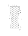
- FIG. 5 is a schematic diagram showing a pattern of a pressing line EL according to the second embodiment.
- the pattern of the squeezing line EL is substantially the same as in the first embodiment.
- the length of the squeezed portion 80 and the length of the non-squeezed portion 86 constituting the squeezing line EL are different from those of the first embodiment.
- the length L1 of the non-squeezed portions 86 along each of the squeezing lines EL is equal to or greater than the width W1 of the squeezed portions in a direction intersecting the squeezing lines EL. This makes it easier for the absorber 40 to curve at the squeeze line EL in a direction intersecting the squeeze line EL. Therefore, the absorber 40 is easily bent to fit the body, and the feel is improved.
- the distance L2 in the front-rear direction L between the non-pressed portions 86 in the adjacent pressed lines EL is shorter than the longer one of the lengths L1 of the respective non-pressed portions 86 along the pressed line EL. Since the distance L2 between the non-pressed portions 86 in the front-rear direction L is short, the tension state of the absorber 40 in the width direction W is relaxed between the non-pressed portions 86. That is, in each cell 46, the force with which the core wrap 40b presses the absorbent core 40a is reduced. Thereby, it can suppress that the absorber 40 becomes too hard, and the touch improves.
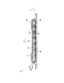
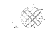
- FIG. 6 is a schematic diagram showing a pattern of a pressing line EL according to the third embodiment.
- the plurality of squeezing lines EL extend along the front-rear direction L and are formed in a waveform that is bent in the width direction. That is, the pressing line EL extends in the front-rear direction L while zigzag in the width direction at a position closest to the virtual line extending in the front-rear direction L.
- the phases of the waveforms of the compression lines EL adjacent to each other are shifted from each other by 180 °.
- each cell 46 is formed in a substantially square shape by the pressing lines EL adjacent to each other.
- Each squeezing line EL includes squeezed parts 80 and non-squeezed parts 86 arranged alternately.
- a certain squeezing line EL and an adjacent squeezing line EL intersect with each other at the closest point.
- a non-pressed portion 86 is provided adjacent to the pressed portion 80 corresponding to the intersection of the cells 46. Even in this case, at least in the crotch region S2, the non-pressed portion 86 is located at a position overlapping the pressed portion 80 of the pressed line EL different from the pressed line EL to which the non-pressed portion 86 belongs, as viewed from the width direction W. Will be provided.
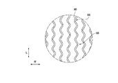
- FIG. 7 is a schematic diagram showing a pattern of a pressing line EL according to the fourth embodiment.
- the plurality of squeezing lines EL extend along the front-rear direction L and are arranged in the width direction W.
- each compression line EL is formed in a waveform that is curved in the width direction.
- the phases of the waveforms of the compression lines EL adjacent to each other are not shifted.
- the pressing line EL does not need to be formed in a lattice shape.
- the non-pressed portion 86 is provided at a position overlapping the pressed portion 80 of the pressed line EL different from the pressed line EL to which the non-pressed portion 86 belongs, as viewed from the width direction W.
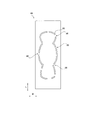
- FIG. 8 is a schematic diagram showing a pattern of a pressing line EL according to the fifth embodiment.
- a pair of squeezing lines EL extend along the front-rear direction L on both sides of the center of the absorber 40 in the width direction W.
- the absorber 40 between the pair of squeezing lines EL is easily deformed in a convex shape toward the skin surface side because the absorber 40 is sandwiched between the legs of the user. Become. Thereby, the absorber 40 is easily fitted to the user's crotch.
- Such a pattern of the squeezing line EL is suitably used as the absorbent body 40 for a sanitary napkin.
- the squeezing line EL may constitute a pattern such as a symbol or a design. Even in this case, it is noted that the non-pressed portion 86 is provided at a position overlapping the pressed portion 80 of the pressed line EL different from the pressed line EL to which the non-pressed portion 86 belongs, as viewed from the width direction W. I want to.
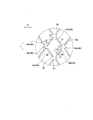
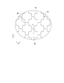
- FIG. 9 is a schematic diagram showing a pattern of a pressing line EL according to the sixth embodiment.
- the plurality of squeezing lines EL extend in the front-rear direction L and are formed in a waveform that is curved in the width direction. That is, the pressing line EL extends in the front-rear direction L while wavyly curving in the width direction at a position closest to an imaginary line extending in the front-rear direction L.
- the phases of the waveforms of the compression lines EL adjacent to each other are shifted from each other by 180 °, and the points where the compression lines EL adjacent to each other come closest to each other are connected by a compression unit along the width direction W.
- the non-pressed portion 86 is located at a position overlapping the pressed portion 80 of the pressed line EL different from the pressed line EL to which the non-pressed portion 86 belongs, as viewed from the width direction W. Is provided.
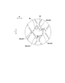
- FIG. 10 is a schematic diagram showing a pattern of a pressing line EL according to the seventh embodiment.
- the pattern of the squeezing line EL is substantially the same as in the first embodiment.
- the position of the non-squeezed portion 86 in the squeezed line EL is different from that of the first embodiment.
- the non-pressed portion 86 is located at a position overlapping with the pressed portion 80 of the pressed line EL different from the pressed line EL to which the non-pressed portion 86 belongs.
- at least a portion of the non-pressed portion 86 may be provided at a position overlapping the pressed portion 80 when viewed from the width direction W. Even in this case, it is difficult to form a folding base point along the width direction W, so that formation of wrinkles along the width direction W can be suppressed.
- the entire non-pressed portion 86 is provided at a position overlapping the pressed portion 80 when viewed from the width direction W. Preferably.
- an absorbent article including an absorbent body having a plurality of squeezed portions intermittently arranged and in which wrinkles are hardly formed in a lateral direction.
Landscapes
- Health & Medical Sciences (AREA)
- Epidemiology (AREA)
- Engineering & Computer Science (AREA)
- Biomedical Technology (AREA)
- Heart & Thoracic Surgery (AREA)
- Vascular Medicine (AREA)
- Life Sciences & Earth Sciences (AREA)
- Animal Behavior & Ethology (AREA)
- General Health & Medical Sciences (AREA)
- Public Health (AREA)
- Veterinary Medicine (AREA)
- Absorbent Articles And Supports Therefor (AREA)
Priority Applications (2)
| Application Number | Priority Date | Filing Date | Title |
|---|---|---|---|
| CN201980043980.4A CN112367954A (zh) | 2018-06-29 | 2019-06-26 | 吸收性物品 |
| SA520420912A SA520420912B1 (ar) | 2018-06-29 | 2020-12-28 | منتج ماص |
Applications Claiming Priority (2)
| Application Number | Priority Date | Filing Date | Title |
|---|---|---|---|
| JP2018-125610 | 2018-06-29 | ||
| JP2018125610A JP6956048B2 (ja) | 2018-06-29 | 2018-06-29 | 吸収性物品 |
Publications (1)
| Publication Number | Publication Date |
|---|---|
| WO2020004457A1 true WO2020004457A1 (ja) | 2020-01-02 |
Family
ID=68986557
Family Applications (1)
| Application Number | Title | Priority Date | Filing Date |
|---|---|---|---|
| PCT/JP2019/025364 Ceased WO2020004457A1 (ja) | 2018-06-29 | 2019-06-26 | 吸収性物品 |
Country Status (4)
| Country | Link |
|---|---|
| JP (1) | JP6956048B2 (enExample) |
| CN (1) | CN112367954A (enExample) |
| SA (1) | SA520420912B1 (enExample) |
| WO (1) | WO2020004457A1 (enExample) |
Families Citing this family (2)
| Publication number | Priority date | Publication date | Assignee | Title |
|---|---|---|---|---|
| JP7666159B2 (ja) * | 2020-08-31 | 2025-04-22 | 王子ホールディングス株式会社 | 吸収性物品 |
| JP2025148165A (ja) * | 2024-03-25 | 2025-10-07 | ユニ・チャーム株式会社 | パンツ型吸収性物品 |
Citations (5)
| Publication number | Priority date | Publication date | Assignee | Title |
|---|---|---|---|---|
| JP2004121382A (ja) * | 2002-09-30 | 2004-04-22 | Daio Paper Corp | 体液吸収性物品 |
| WO2011142272A1 (ja) * | 2010-05-10 | 2011-11-17 | 大王製紙株式会社 | 使い捨て吸収性物品 |
| JP2014100262A (ja) * | 2012-11-20 | 2014-06-05 | Uni Charm Corp | 吸収性物品 |
| JP2016106991A (ja) * | 2014-12-10 | 2016-06-20 | 王子ホールディングス株式会社 | 吸収性物品 |
| JP2018082927A (ja) * | 2016-11-24 | 2018-05-31 | 王子ホールディングス株式会社 | 吸収性物品 |
Family Cites Families (2)
| Publication number | Priority date | Publication date | Assignee | Title |
|---|---|---|---|---|
| JP4401750B2 (ja) * | 2003-11-25 | 2010-01-20 | 大王製紙株式会社 | 吸収体の製造方法およびこれにより得られた使い捨ておむつ用吸収体 |
| JP6021567B2 (ja) * | 2012-09-30 | 2016-11-09 | ユニ・チャーム株式会社 | 吸収性物品 |
-
2018
- 2018-06-29 JP JP2018125610A patent/JP6956048B2/ja active Active
-
2019
- 2019-06-26 WO PCT/JP2019/025364 patent/WO2020004457A1/ja not_active Ceased
- 2019-06-26 CN CN201980043980.4A patent/CN112367954A/zh active Pending
-
2020
- 2020-12-28 SA SA520420912A patent/SA520420912B1/ar unknown
Patent Citations (5)
| Publication number | Priority date | Publication date | Assignee | Title |
|---|---|---|---|---|
| JP2004121382A (ja) * | 2002-09-30 | 2004-04-22 | Daio Paper Corp | 体液吸収性物品 |
| WO2011142272A1 (ja) * | 2010-05-10 | 2011-11-17 | 大王製紙株式会社 | 使い捨て吸収性物品 |
| JP2014100262A (ja) * | 2012-11-20 | 2014-06-05 | Uni Charm Corp | 吸収性物品 |
| JP2016106991A (ja) * | 2014-12-10 | 2016-06-20 | 王子ホールディングス株式会社 | 吸収性物品 |
| JP2018082927A (ja) * | 2016-11-24 | 2018-05-31 | 王子ホールディングス株式会社 | 吸収性物品 |
Also Published As
| Publication number | Publication date |
|---|---|
| SA520420912B1 (ar) | 2025-05-22 |
| CN112367954A (zh) | 2021-02-12 |
| JP2020000758A (ja) | 2020-01-09 |
| JP6956048B2 (ja) | 2021-10-27 |
Similar Documents
| Publication | Publication Date | Title |
|---|---|---|
| JP4401309B2 (ja) | 吸収性物品 | |
| JP5698513B2 (ja) | 吸収性物品 | |
| JP2005000312A (ja) | 吸収性物品およびその製造方法 | |
| JP2006020893A (ja) | 生理用ナプキン | |
| JP4877850B2 (ja) | 吸収性物品 | |
| JP6901272B2 (ja) | 吸収性物品 | |
| JP6001984B2 (ja) | 吸収性物品 | |
| JP2017000329A (ja) | 吸収性物品 | |
| WO2020004457A1 (ja) | 吸収性物品 | |
| JP5978349B1 (ja) | 吸収性物品 | |
| WO2020004446A1 (ja) | 吸収性物品 | |
| JP2014068995A (ja) | 吸収性物品 | |
| JP5944953B2 (ja) | 吸収性物品 | |
| WO2014119218A1 (ja) | 吸収性物品 | |
| JP6118748B2 (ja) | 使い捨ておむつ | |
| JP6051285B1 (ja) | 吸収性物品 | |
| JP2020124314A (ja) | 吸収性物品 | |
| WO2020162386A1 (ja) | 吸収性物品 | |
| JP3238580U (ja) | 吸収性物品 | |
| JP2020011113A (ja) | 吸収性物品 | |
| JP2020075085A (ja) | 吸収性物品 | |
| JP6705871B2 (ja) | 吸収性物品 | |
| JP2024091079A (ja) | 体液吸収シート | |
| JP2024091080A (ja) | 体液吸収シート | |
| JP2019022785A (ja) | 吸収性物品 |
Legal Events
| Date | Code | Title | Description |
|---|---|---|---|
| 121 | Ep: the epo has been informed by wipo that ep was designated in this application |
Ref document number: 19824884 Country of ref document: EP Kind code of ref document: A1 |
|
| NENP | Non-entry into the national phase |
Ref country code: DE |
|
| 122 | Ep: pct application non-entry in european phase |
Ref document number: 19824884 Country of ref document: EP Kind code of ref document: A1 |
|
| WWE | Wipo information: entry into national phase |
Ref document number: 520420912 Country of ref document: SA |
|
| WWE | Wipo information: entry into national phase |
Ref document number: 520420912 Country of ref document: SA |
|
| WWE | Wipo information: entry into national phase |
Ref document number: 520420912 Country of ref document: SA |
|
| WWG | Wipo information: grant in national office |
Ref document number: 520420912 Country of ref document: SA |