WO2020004405A1 - 複合部材および成形用型、複合部材の製造方法およびガラス材料の成形方法ならびに光学素子、光学系、および撮像装置 - Google Patents
複合部材および成形用型、複合部材の製造方法およびガラス材料の成形方法ならびに光学素子、光学系、および撮像装置 Download PDFInfo
- Publication number
- WO2020004405A1 WO2020004405A1 PCT/JP2019/025206 JP2019025206W WO2020004405A1 WO 2020004405 A1 WO2020004405 A1 WO 2020004405A1 JP 2019025206 W JP2019025206 W JP 2019025206W WO 2020004405 A1 WO2020004405 A1 WO 2020004405A1
- Authority
- WO
- WIPO (PCT)
- Prior art keywords
- glass
- glass member
- base material
- mold
- composite member
- Prior art date
- Legal status (The legal status is an assumption and is not a legal conclusion. Google has not performed a legal analysis and makes no representation as to the accuracy of the status listed.)
- Ceased
Links
Images




Classifications
-
- B—PERFORMING OPERATIONS; TRANSPORTING
- B32—LAYERED PRODUCTS
- B32B—LAYERED PRODUCTS, i.e. PRODUCTS BUILT-UP OF STRATA OF FLAT OR NON-FLAT, e.g. CELLULAR OR HONEYCOMB, FORM
- B32B17/00—Layered products essentially comprising sheet glass, or glass, slag, or like fibres
- B32B17/06—Layered products essentially comprising sheet glass, or glass, slag, or like fibres comprising glass as the main or only constituent of a layer, next to another layer of a specific material
-
- C—CHEMISTRY; METALLURGY
- C03—GLASS; MINERAL OR SLAG WOOL
- C03B—MANUFACTURE, SHAPING, OR SUPPLEMENTARY PROCESSES
- C03B11/00—Pressing molten glass or performed glass reheated to equivalent low viscosity without blowing
-
- C—CHEMISTRY; METALLURGY
- C03—GLASS; MINERAL OR SLAG WOOL
- C03B—MANUFACTURE, SHAPING, OR SUPPLEMENTARY PROCESSES
- C03B11/00—Pressing molten glass or performed glass reheated to equivalent low viscosity without blowing
- C03B11/06—Construction of plunger or mould
- C03B11/08—Construction of plunger or mould for making solid articles, e.g. lenses
Definitions
- the present invention relates to a composite member including a glass member and a base material, a molding die using the composite member, a method of manufacturing the composite member, a method of molding a glass material, an optical element, an optical system, and an imaging device.
- press molding As a molding material for performing glass mold press molding (hereinafter referred to as “press molding”) on glass materials, metal, cemented carbide, ceramic, etc.
- a material having a high Young's modulus is used. However, in general, the harder the material, the longer it takes to process the mold.
- Patent Document 1 describes an example in which press molding is performed on a glass material using a molding die made of glass.
- the Young's modulus of glass is smaller than that of members such as metals, cemented carbides, and ceramics. Therefore, the deformation (deformation from a desired shape) of the glass material during forming is greater than when a forming die made of a member such as metal, cemented carbide, or ceramic is used.
- Patent Document 2 describes a molding die in which crystallized glass as a glass member is disposed on a high-speed steel base material.
- Patent Document 3 describes a composite member (a glass material press-molding die) including a glass member and a base material.
- Non-Patent Document 1 describes a method for evaluating the warpage of the laminate.
- Non-Patent Document 2 discloses the shape of a molded spherical lens when performing mold press molding of a spherical lens using S-BSL7, which is a compatible material of BK-7 glass, as a glass material and a cemented carbide as a mold. It describes that it is related to the evaluation.
- the molding die when the glass member and the base material are joined, the molding die may be distorted due to thermal stress generated at the time of joining.
- press forming of a glass material is performed at a high temperature such as 600 ° C.
- a high temperature such as 600 ° C.
- the glass member and the base material are joined at a temperature of 800 to 1000 ° C., which is higher than the molding temperature, a large thermal stress occurs at room temperature. Thermal stress increases the likelihood of breakage of the glass member. Further, the thermal stress increases the possibility that the glass member is deformed.
- An object of the present invention is to reduce thermal deformation occurring in a composite member including a glass member and a base material.
- the composite member according to the present invention is a composite member including a glass member that is a forming part and a substrate that supports the glass member, wherein the thickness of the glass member is Hm, the Young's modulus of the glass member is Em, and the glass member is The linear expansion coefficient is ⁇ m, the width of the glass member is W, the thickness of the substrate is Hs, the Young's modulus of the substrate is Es, and the linear expansion coefficient of the substrate is ⁇ s.
- the warp ⁇ H of the glass member is less than 0.004 mm.
- the molding die according to the present invention is a molding die including two mold members provided to face each other, wherein at least one of the two mold members is the above-described composite member.
- the method for producing a composite member according to the present invention is a method for producing a composite member in which a glass member that is a forming part and a base material that supports the glass member are joined to produce a composite member, and the thickness of the glass member is reduced.
- Hm the Young's modulus of the glass member is Em
- the linear expansion coefficient of the glass member is ⁇ m
- the width of the glass member is W
- the thickness of the substrate is Hs
- the Young's modulus of the substrate is Es
- the linear expansion coefficient of the substrate is ⁇ s.
- the warp ⁇ H of the glass member when the temperature difference ⁇ T between the temperature at which the warp of the glass member is 0 and room temperature is 1000 ° C. is 0.004 mm
- the glass member and the base material are selected so as to be less than the above, and the glass member and the base material are joined.
- the method for molding a glass material according to the present invention is characterized in that the glass material is molded using the above-described mold.
- thermal deformation generated in a composite member including a glass member and a substrate can be reduced.
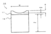
- FIG. 1 is a cross-sectional view schematically illustrating a mold member that is an example of a composite member.
- FIG. 2 is a cross-sectional view schematically illustrating another example of the mold member.
- FIG. 3 is an explanatory diagram showing the amount of displacement with respect to the thickness Hm when the Young's modulus of the glass is 70 GPa and a pressure of 1 MPa is applied to the surface of the glass.
- FIG. 4 is a sectional view schematically showing a molding die including two mold members.
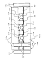
- FIG. 5 is a cross-sectional view schematically illustrating another molding die.
- FIG. 6 is a cross-sectional view schematically showing a state in which a glass material is molded using the mold member shown in FIG.
- FIG. 7 is an explanatory diagram showing the results of a simulation when the thickness of the formed part is changed.
- FIG. 1 is a sectional view schematically showing a mold member 10 which is an example of a composite member according to the present invention.
- the mold member 10 includes a molded part 11 and a base material 12.
- the forming part 11 is a glass member made of glass.
- the molding part 11 is joined to the base material 12.
- the joining is, for example, joining via another member such as soldering or brazing.
- the molded portion 11 and the base material 12 may be directly joined by using a chemical bond such as an intermolecular force or a covalent bond, for example, by pressing at a high temperature.
- a material having a high Young's modulus such as a metal, a cemented carbide, or a ceramic can be used.
- the Young's modulus of the substrate 12 is preferably 150 GPa or more, more preferably 300 GPa or more, and even more preferably 450 GPa or more. Although there is no particular upper limit for the Young's modulus, the range of the Young's modulus of a generally available material is 1100 GPa or less for diamond.
- a tensile test, a compression test, a torsion test, a resonance method, an ultrasonic pulse method, a pendulum method and the like can be used.
- JIS R1602 1995 "Test method for elastic modulus of fine ceramics”
- JIS R1605 1995 "Test method for high temperature elastic modulus of fine ceramics”
- JIS Z2201 1998
- Metallic material tensile test piece JIS Z2241: 2011
- JIS G0567J 2012
- High-temperature tensile test method for steel materials and heat-resistant alloys JIS Z2280: 1993
- W represents the width of the molded portion 11.
- Hs represents the thickness of the substrate.
- Hm represents the thickness of the molded part 11.
- the thickness of the molded portion 11 at the bottom of the concave portion can be used when the surface of the molded portion 11 is concave, and the thickness of the molded portion 11 at the end of the convex portion when the surface of the molded portion 11 is convex.
- the width W a minimum width of an in-plane dimension can be used. In the case where the end of the molded portion 11 is smoothly connected to the base material 12, the average width of the portion of the molded portion 11 whose height is equal to or less than Hm can be used as the width W.
- W (h) represents the width of the molded portion 11 at the height h.
- the forming portion 11 has a curved surface for forming, and the depth is S.
- the surface of the molded portion 11 may be covered with an intermediate film or a protective film. Further, an adhesive layer may be provided between the molded portion 11 and the base material 12. Titanium, zirconium, niobium, hafnium, tantalum, chromium, molybdenum, tungsten, ruthenium, rhodium, iron, cobalt, nickel, palladium, rhenium, osmium, iridium, copper, silver, gold, platinum Metals, noble metals, alloys thereof, oxides, nitrides, oxynitrides, and carbides can be used.
- silicon compounds such as silicon, silicon dioxide, silicon nitride, silicon oxynitride, and silicon carbide, carbon such as amorphous carbon and diamond-like carbon, and boron compounds can be used.
- the film may be multi-layered by a plurality of materials.
- the surface shape of the molded portion 11 is not limited to an axisymmetric aspherical shape in a cross-sectional view, and may be a shape such as a free-form surface. Further, the surface of the molded portion 11 is not limited to a concave surface, and may be a convex surface.
- the shape of the longitudinal section of the base material 12 is a square.
- the shape of the longitudinal section of the substrate 12 is not limited to a square.
- the shape of the cross section of the base material 12 is circular as an example.
- FIG. 2 is a cross-sectional view schematically showing another example of the mold member.
- the base material 12 may have a structure having a flange as shown in FIG. Further, the base material 12 may have a structure having a through hole or a screw hole in a part. Further, as shown in FIG. 2B, the width of the molded portion 11 and the width of the base material 12 may be different. As shown in FIG. 2C, the configuration may be such that the molded portion 11 is arranged in the concave portion of the base material 12 provided with the concave portion.
- the strain point of the glass used for the forming part 11 is preferably 400 ° C. or higher, more preferably 500 ° C. or higher, even more preferably 600 ° C. or higher.
- the reason is that the molding temperature of many optical glasses is in the range of 400 to 600 ° C., and it is necessary that the shape can be sufficiently maintained during molding in this temperature range.
- the strain point can be measured by a method specified in JIS-R3103-2: 2001 or the like. Although there is no particular upper limit on the strain point of glass, quartz glass is a generally available material, and the strain point is 1200 ° C. or less.
- the bond in order to form a bond that is durable at the glass forming temperature, it is preferable to form the bond at a temperature of 600 ° C. or higher. More preferably, the junction is formed at a temperature of 800 ° C. or higher. Further, even if bonding can be performed at a temperature close to room temperature without warpage, it is necessary to consider the warpage that occurs when the temperature is raised to the glass forming temperature. Since the upper limit of the temperature for forming the bond is preferably equal to or lower than the strain point of the glass, the upper limit can be set to 1200 ° C. or lower.
- E k represents the elastic modulus of each layer.
- ⁇ k represents the coefficient of linear expansion of each layer.
- Z k represents a position in the thickness direction of the interface of each layer from settable reference coordinates at any position.
- t represents a temperature difference from the reference temperature.
- K represents the curvature K of the deformation of the laminate caused by the temperature difference t.
- ⁇ H is represented by the following equation (2).
- the two layers correspond to the molded portion 11 and the base material 12.
- K (A ⁇ FB ⁇ D) / (A ⁇ CB 2 )
- A Es ⁇ Hs + Em ⁇ Hm
- B (1 /) ⁇ [Es ⁇ Hs 2 + Em ⁇ ⁇ (Hs + Hm) 2 ⁇ Hs 2 ⁇ ]
- C (1 /) ⁇ [Es ⁇ Hs 3 + Em ⁇ ⁇ (Hs + Hm) 3 ⁇ Hs 3 ⁇ ]
- Em indicates the Young's modulus of the glass member that is the forming part 11.
- ⁇ m indicates a linear expansion coefficient of the glass member that is the forming part 11.
- Es indicates the Young's modulus of the substrate 12.
- ⁇ s indicates the coefficient of linear expansion of the substrate 12.
- ⁇ T is the difference between the temperature at which the mold member 10 is molded (the joining temperature at which the molded portion 11 and the base material 12 are joined: in other words, the temperature at which the warpage of the glass member is 0) and the room temperature.
- the room temperature is a temperature in the range of 20 to 25 ° C., and unless otherwise noted, 20 ° C.
- the unit of Es and Em is [MPa].
- the unit of Hm and Hs is [mm].
- the unit of the linear expansion coefficient is [1 / ° C.].
- the unit of ⁇ T is [° C.].
- the unit of ⁇ H is [mm].
- the coefficient of linear expansion can be measured using a thermomechanical analyzer (TMA). Further, a method according to the following JIS standard may be used. JIS Z2285: 2003 Method of measuring linear expansion coefficient of metal material JIS R1618: 2002 Method of measuring thermal expansion of fine ceramics by thermomechanical analysis JIS R3251: 1995 Method of measuring linear expansion coefficient of low expansion glass by laser interference method JIS R3102: 1995 Test method for average coefficient of linear expansion of glass
- the number of layers of the laminate (the molded part 11 and the base material 12) is two. Therefore, the warpage is evaluated by the above equations (2) and (3).
- the molded part 11 and the base material 12 are joined by soldering, brazing, or the like, an adhesive layer is interposed between the molded part 11 and the base material 12, but the adhesive layer is formed between the molded part 11 and the base material 12.
- the above equation (3) can be used assuming that the influence of the adhesive layer is small.
- the above equation (1) is used instead of the above equation (3). May be used to calculate K.
- Whether or not the influence of the adhesive layer can be ignored is determined by, for example, Expression (2) using the result of calculating K by Expression (1).
- K may be calculated using the above equation (1). Good.
- the width W of the molded portion 11 is preferably 20 mm or less, more preferably 10 mm or less, even more preferably 5 mm or less.
- the width of the molded part 11 may be any value larger than 0.
- the difference between the linear expansion coefficient ⁇ m of the molded part 11 and the linear expansion coefficient ⁇ s of the base material 12 is preferably 3 ⁇ 10 ⁇ 6 [1 / ° C.] or less, and preferably 2 ⁇ 10 ⁇ 6 [1 / ° C.] or less. Is more preferable. It is preferable to use ceramics such as alumina, silicon nitride, and silicon carbide or a cemented carbide as the material of the base material 12 because the Young's modulus of the base material can be increased.
- the linear expansion coefficient of the glass of the material of the molded portion 11 is also in such a range. Note that the lower limit of the difference between the linear expansion coefficients is 0.
- the thickness Hm of the molded portion 11 is preferably thinner from the viewpoint that the displacement during molding is small.
- FIG. 3 shows the amount of displacement in the thickness direction with respect to the thickness Hm when the Young's modulus of the glass is 70 GPa and a pressure of 1 MPa is applied to the surface of the glass.
- the thickness Hm of the molded portion 11 is preferably 6 mm or less. More preferably, it is 3 mm or less. More preferably, it is 1 mm or less. More preferably, it is 0.5 mm or less. Note that Hm may be any value greater than 0.
- the warp ⁇ H of the molded portion 11 is 0.
- a condition of less than .004 mm is derived.
- the thickness Hs of the substrate may be any value greater than 0. Further, if the base material is too thick, there is a problem such as an increase in heat capacity during heating. Therefore, Hs is preferably 100 mm or less, more preferably 50 mm or less, and even more preferably 20 mm or less.
- the depth S of the molded portion 11 is preferably 2 mm or less, more preferably 1 mm or less, and even more preferably 0.75 mm or less. By doing so, non-uniform shape deformation due to a difference in glass thickness can be suppressed.
- the depth S of the formed portion 11 may be larger than 0.
- FIG. 4 is a cross-sectional view schematically showing a molding die including two mold members (a first mold member 10a and a second mold member 10b) provided to face each other.
- the molding die shown in FIG. 4 is a first mold member 10a having a molding portion 11a made of glass and a base material 12a, and a second die having a molding portion 11b made of glass material and a base material 12b.
- a member 10b, a guide member 21 provided to surround the first mold member 10a and the second mold member 10b to accommodate the first mold member 10a and the second mold member 10b, and an inner member 22.
- the glass material 23 is formed by pressing the first mold member 10a or the second mold member 10b.
- Both the first mold member 10a and the second mold member 10b are members manufactured based on the above-described preferred value parameters.
- one of the two mold members may be a member manufactured based on the above-described preferable value parameter.
- one of the two mold members may be a mold member other than the above-described composite member (that is, a composite member including a glass member that is a molded portion and a base material that supports the glass member).
- one of the two mold members may be constituted by a single member, or may be a composite member including a molded part made of a material other than a glass material with respect to the base material.
- a metal, a cemented carbide, a ceramic, or the like can be used as a molding member other than a mold member or a glass material using such a single material.
- the surface shapes of the molding portions of the facing mold members can be freely designed. That is, the surface shape of each molded portion is not limited to an axisymmetric aspherical shape in cross-sectional view, and may be a shape such as a concave, convex, or wavy free-form surface or a flat shape. Further, the facing mold members may not have the same surface shape.
- the surface shape of one molded portion may be a concave curved surface shape
- the surface shape of the other molded portion may be a convex shape or a flat shape. .
- the combination of the surface shapes of the molding portions of the facing mold members is not limited to this.
- the surface of the molded portion included in the mold member may be coated with the above-described intermediate film or protective film.
- a release treatment such as applying a release agent may be performed on the surface of the molded portion included in the mold member.
- the inner member 22 has, for example, a ring-like structure.
- the inner member 22 is used to determine the outer shape of the glass material 23 at the time of molding. When it is not necessary to determine the outer shape, the inner member 22 may not be provided.
- members such as glass, metal, ceramics, and cemented carbide can be used. Further, when the respective linear expansion coefficients of the first mold member 10a, the second mold member 10b, the inner member 22, and the guide member 21 are ⁇ 10a, ⁇ 10b, ⁇ 22, and ⁇ 21, respectively, ⁇ 10a ⁇ ⁇ 10b ⁇ ⁇ 21, or ⁇ 22 ⁇ ⁇ 21 may be satisfied. In such a case, the gap between the members during thermal expansion can be reduced, and for example, eccentricity between the first mold member 10a and the second mold member 10b can be suppressed.
- FIG. 4 illustrates a molding die having a configuration in which a set of a first die member 10a and a second die member 10b are arranged inside a guide member 21, but the molding die is not shown.
- the present invention is not limited to such a structure.
- a plurality of through holes may be provided in the guide member 21 and a plurality of sets of the first mold member 10a and the second mold member 10b may be arranged.
- FIG. 5 is a cross-sectional view schematically showing another molding die.
- the molding die shown in FIG. 5 includes a first mold member 10c (composite member) having a molding portion 11c made of glass and a base material 12c, and a molding portion 11d made of glass and a base material 12d. It includes a second mold member 10d (composite member), a guide member 31, an inner member 32, and a pin member 33.
- the glass material 23 is formed by pressing the first mold member 10c or the second mold member 10d.
- the first mold member 10c and the second mold member 10d have a plurality of molding parts 11c and 11d made of glass, respectively.
- the first mold member 10c and the second mold member 10d are provided with through holes through which the pin members 33 pass.
- the rotation of the first mold member 10c and the second mold member 10d is suppressed by the pin member 33.
- a plurality of through holes for passing the pin member 33 may be provided.
- Both the first mold member 10c and the second mold member 10d are members manufactured based on the above-described preferable value parameters.
- one of the two mold members may be a member manufactured based on the above-described preferable value parameter.
- ⁇ T 1000, , ⁇ H ⁇ 0.0005.
- only the number of molding parts included in one mold member is different from that of the example of FIG.
- one of the two mold members is a mold member other than the above-described composite member (for example, As in the example shown in FIG. 4, a mold member made of a single material as described above or a composite member including a molded part made of a material other than a glass material with respect to a base material may be used.
- a mold member made of a single material as described above or a composite member including a molded part made of a material other than a glass material with respect to a base material may be used.
- the lower limit of ⁇ H is 0 as can be seen from equation (2).
- the inner member 32 is formed, for example, in a plate shape provided with a plurality of through holes.
- the inner member 32 can be used to determine the outer shape of the glass material 23 at the time of molding. When it is not necessary to determine the outer shape of the glass material 23, the inner member 32 may be omitted.
- the inner member 32 and the pin member 33 members such as glass, metal, ceramics, and cemented carbide can be used. Further, when the linear expansion coefficients of the first mold member 10c, the second mold member 10d, the inner member 32, the guide member 31, and the pin member 33 are ⁇ 10c, ⁇ 10d, ⁇ 32, ⁇ 31, and ⁇ 33, ⁇ 10c ⁇ ⁇ 10d ⁇ ⁇ 31. Alternatively, ⁇ 33 ⁇ ⁇ 10c ⁇ ⁇ 10d, or ⁇ 32 ⁇ ⁇ 31, or ⁇ 33 ⁇ ⁇ 32.
- a mold having a shape corresponding to the outer shape of the molding portion 11 or the molding portion 11c (or the molding portion 11d) is prepared.
- the molding unit 11 or the molding unit 11c (or the molding unit 11d) is manufactured using such a mold.
- the base material 12 or the base material 12c (or the base material 12d) is prepared.
- the material parameters of the base material 12 or the base material 12c (or the base material 12d) are selected such that ⁇ H calculated using the above equation (2) is 0.004 mm or less.
- ⁇ T is 1000 ° C.
- a glass member having a strain point of 600 ° C. or more is used as the base material 12 or the base material 12c (or the base material 12d).
- the molding part 11 or the molding part 11c (or the molding part 11d) and the base material 12 or the base material 12c (or the base material 12d) are joined in a high temperature environment (for example, 800 ° C.).
- a high temperature environment for example, 800 ° C.
- the joining method is as described above.
- the high temperature environment is a temperature environment that is equal to or higher than the temperature at which the glass material 23 is formed.
- a mold member for molding the glass material 23 is described as an example, but the use of the mold member is not limited to glass molding.
- the mold member can be used as a mold for molding a resin material such as a thermosetting resin or a UV curing resin. Further, the production of the molded part 11 and the joining of the molded part 11 and the base material 12 may be performed simultaneously in a high-temperature environment.
- the first mold member 10a Places the glass material 23 on the second mold member 10b. Thereafter, the first mold member 10a is lowered to a predetermined position. Next, the composite member (the first mold member 10a and the second mold member 10b) is heated to the temperature at the time of press molding (for example, 600 ° C.), and the first mold member 10a is pressed. Thereafter, the composite member and the formed glass material 23 are gradually cooled, the first mold member 10a is raised, and the formed glass material 23 is taken out.
- the time of press molding for example, 600 ° C.
- the second mold member 10b may be raised.
- the glass material 23 is molded by the same method when the molding die shown in FIG. 5 is used.
- the molded portion 11 is a glass member having a Young's modulus of 80 GPa and a linear expansion coefficient of 3.2 ⁇ 10 ⁇ 6 [1 / ° C.].
- the thickness Hm of the molded portion 11 is 0.13 mm.
- the width W of the molded portion 11 is 2.3 mm.
- the surface shape of the molded portion 11 is a spherical surface having a radius of curvature of 1.13 mm.
- the depth S of the spherical surface is 0.37 mm.
- the base material 12 is a cemented carbide having a Young's modulus of 600 GPa and a coefficient of linear expansion of 5.5 ⁇ 10 ⁇ 6 [1 / ° C.].
- the thickness Hs of the substrate 12 is 5 mm.
- FIG. 6 is a cross-sectional view schematically showing a state in which the glass material 23 is formed using the mold member shown in FIG.
- FIG. 6A shows, as a mold member, a second mold member 10f having a molded portion 11f made of glass and a base material 12f.
- a first mold member 10e having a molded portion 11e made of glass and a base material 12e is shown.
- the surface shape of the molded portion 11e is an aspheric surface having a spherical surface with a radius of curvature of 1.76 mm as an approximate shape, and has a convex shape toward the outside.
- FIG. 6B a glass molded product 24 is obtained.
- the displacement in the thickness direction of the molded portion 11f after the molding was calculated.
- the calculation by the finite element method also confirmed that the average value of the displacement was as small as 8 nm.
- FIG. 7 shows a simulation result. As shown in FIG. 7, it was confirmed that the displacement amount became smaller as the molded portion 11f became thinner.
- the molded part 11 is a glass member having a Young's modulus of 70 GPa and a linear expansion coefficient of 4.0 ⁇ 10 ⁇ 6 [1 / ° C.].
- the base material 12 is a cemented carbide having a Young's modulus of 500 GPa and a coefficient of linear expansion of 5.5 ⁇ 10 ⁇ 6 [1 / ° C.].
- the thickness Hs of the substrate 12 is 10 mm.
- the thickness Hm of the molded part 11 is 10 mm.
- the width W of the molded part 11 is 20 mm. The values of these parameters correspond to the values described in column [4] of Table 1.
- the optical element formed by the method for forming the glass material 23 of the present embodiment is a glass lens, but is not limited thereto, and may be a lens made of a light-transmitting material, for example, a light-transmitting resin.
- the shape of the glass lens is not limited, and may be aspherical, spherical, or flat.
- the optical element can be applied (for example, incorporated) to various optical systems.
- the optical system for example, there are a lens that cooperates with the above-mentioned optical element, an optical filter such as an antireflection film or a band-pass filter, a cover glass, and an aperture.
- an optical filter such as an antireflection film or a band-pass filter
- a cover glass for example, glass, glass, glass, and an aperture.
- optical element is applied to an imaging device such as a camera.
Landscapes
- Engineering & Computer Science (AREA)
- Chemical & Material Sciences (AREA)
- Manufacturing & Machinery (AREA)
- Materials Engineering (AREA)
- Organic Chemistry (AREA)
- Moulds For Moulding Plastics Or The Like (AREA)
- Laminated Bodies (AREA)
Abstract
本発明は、ガラス部材と基材とを含む複合部材に生じる熱変形を緩和することを目的とする。本発明は、成形部であるガラス部材と、前記ガラス部材を支持する基材とを含む複合部材であって、前記ガラス部材の厚さをHm、前記ガラス部材のヤング率をEm、前記ガラス部材の線膨張係数をαm、前記基材の厚さをHs、前記基材のヤング率をEs、前記基材の線膨張係数をαsで表した特定の式を使用したときに、前記ガラス部材の反りが0である温度と室温との温度差ΔT=1000℃の場合の前記ガラス部材の反りΔHが0.004mm未満である、複合部材に関する。ΔHは明細書中に定義されている。
Description
本発明は、ガラス部材と基材とを含む複合部材、複合部材を用いた成形用型、複合部材の製造方法およびガラス材料の成形方法ならびに光学素子、光学系、および撮像装置に関する。
ガラス材料に対してガラスモールドプレス成形(以下、プレス成形という。)を行うための成形用型の形材として、成形中のガラス材料の変形を抑えるために、金属、超硬合金、セラミックなどのヤング率の高い材料が用いられる。しかし、一般に、硬い材質ほど成形用型の加工に時間がかかる。
成形用型の形材として、ガラスのような加工性がよい材質を用いると、成形用型の加工の時間を短縮できる。ガラスは、エッチング、切削、研磨、プレス成形など様々な加工方法によって多様な形状のガラス加工品に加工可能である。そのようなガラス加工品でUV硬化樹脂のインプリントの型を形成することができる。また、特許文献1には、ガラスを材料とした成形用型を用いてガラス材料に対してプレス成形を行う例が記載されている。
しかし、ガラスのヤング率は、金属、超硬合金、セラミックなどの部材のヤング率に比べて小さい。したがって、金属、超硬合金、セラミックなどの部材による成形用型を用いる場合に比べて、成形中のガラス材料の変形(所望の形状からの変形)が大きくなる。
特許文献2には、高速度鋼の基材の上にガラス部材としての結晶化ガラスを配置した成形用型が記載されている。
特許文献3には、ガラス部材と基材からなる複合部材(ガラス材料プレス成形用型)が記載されている。
なお、非特許文献1には、積層体の反りの評価方法が記載されている。非特許文献2には、BK-7ガラスの互換材であるS-BSL7をガラス材料とし、超硬合金を金型として球面レンズのモールドプレス成形を行った際の、成形された球面レンズの形状の評価に関することが記載されている。
山科 直利、「特5 銅張り積層板のそりのメカニズム」、討論会講演要旨、合成樹脂工業協会、1985年、第35巻、p.125-128
伊藤 寛明他3名、「ガラスレンズのモールドプレスにおける最適成形条件の評価」、日本機械学会論文集(A編)、2013年11月、第79巻、第807号、p.131-135
ガラス部材と基材を含む成形用型を形成する場合、ガラス部材と基材とを接合するときに、接合の際に発生する熱応力によって成形用型が歪む場合がある。一般に、ガラス材料のプレス成形は、600℃などの高温で行われる。例えば、成形温度より高温の800~1000℃でガラス部材と基材との接合がなされた場合、室温になったときに、大きな熱応力が生じる。熱応力は、ガラス部材の破損の可能性を高める。また、熱応力は、ガラス部材に変形を生じさせる可能性を高める。
本発明は、ガラス部材と基材とを含む複合部材に生じる熱変形を緩和することを目的とする。
本発明による複合部材は、成形部であるガラス部材と、ガラス部材を支持する基材とを含む複合部材であって、ガラス部材の厚さをHm、ガラス部材のヤング率をEm、ガラス部材の線膨張係数をαm、ガラス部材の幅をW、基材の厚さをHs、基材のヤング率をEs、基材の線膨張係数をαsで表して、ガラス部材の反りΔHを下記の式によって定義したときに、ガラス部材の反りが0である温度と室温との温度差ΔTが1000℃の場合のガラス部材の反りΔHが0.004mm未満であることを特徴とする。
ΔH=(1/|K|)-√{(1/K)2-(W/2)2}
(式において、
K=(A×F-B×D)/(A×C-B2)
A=Es×Hs+Em×Hm
B=(1/2)×[Es×Hs2+Em×{(Hs+Hm)2-Hs2}]
C=(1/3)×[Es×Hs3+Em×{(Hs+Hm)3-Hs3}]
D=ΔT×{Es×αs×Hs+Em×αm×Hm}
F=(ΔT/2)×[Es×αs×Hs2+Em×αm×{(Hs+Hm)2-Hs2}])
ΔH=(1/|K|)-√{(1/K)2-(W/2)2}
(式において、
K=(A×F-B×D)/(A×C-B2)
A=Es×Hs+Em×Hm
B=(1/2)×[Es×Hs2+Em×{(Hs+Hm)2-Hs2}]
C=(1/3)×[Es×Hs3+Em×{(Hs+Hm)3-Hs3}]
D=ΔT×{Es×αs×Hs+Em×αm×Hm}
F=(ΔT/2)×[Es×αs×Hs2+Em×αm×{(Hs+Hm)2-Hs2}])
本発明による成形用型は、互いに対向して設けられた2つの型部材を含む成形用型であって、2つの型部材のうちの少なくとも一方が上記の複合部材であることを特徴とする。
本発明による複合部材の製造方法は、成形部であるガラス部材と、ガラス部材を支持する基材とを接合して複合部材を作製する複合部材の製造方法であって、ガラス部材の厚さをHm、ガラス部材のヤング率をEm、ガラス部材の線膨張係数をαm、ガラス部材の幅をW、基材の厚さをHs、基材のヤング率をEs、基材の線膨張係数をαsで表して、ガラス部材の反りΔHを下記の式によって定義したときに、ガラス部材の反りが0である温度と室温との温度差ΔTが1000℃の場合のガラス部材の反りΔHが0.004mm未満であるように、ガラス部材と基材とを選定し、ガラス部材と基材とを接合することを特徴とする。
ΔH=(1/|K|)-√{(1/K)2-(W/2)2}
(式において、
K=(A×F-B×D)/(A×C-B2)
A=Es×Hs+Em×Hm
B=(1/2)×[Es×Hs2+Em×{(Hs+Hm)2-Hs2}]
C=(1/3)×[Es×Hs3+Em×{(Hs+Hm)3-Hs3}]
D=ΔT×{Es×αs×Hs+Em×αm×Hm}
F=(ΔT/2)×[Es×αs×Hs2+Em×αm×{(Hs+Hm)2-Hs2}])
ΔH=(1/|K|)-√{(1/K)2-(W/2)2}
(式において、
K=(A×F-B×D)/(A×C-B2)
A=Es×Hs+Em×Hm
B=(1/2)×[Es×Hs2+Em×{(Hs+Hm)2-Hs2}]
C=(1/3)×[Es×Hs3+Em×{(Hs+Hm)3-Hs3}]
D=ΔT×{Es×αs×Hs+Em×αm×Hm}
F=(ΔT/2)×[Es×αs×Hs2+Em×αm×{(Hs+Hm)2-Hs2}])
本発明によるガラス材料の成形方法は、上記の成形用型を用いてガラス材料を成形することを特徴とする。
本発明によれば、ガラス部材と基材とを含む複合部材に生じる熱変形を緩和することができる。
図1は、本発明による複合部材の一例である型部材10を模式的に示す断面図である。型部材10は、成形部11と基材12とを含む。成形部11は、ガラスを材料とするガラス部材である。成形部11は、基材12と接合されている。接合は、例えば、はんだ付けやろう付けなどの他の部材を介した接合である。成形部11と基材12とを高温中でプレスするなどして、分子間力や共有結合などの化学的な結合を利用して直接接合させてもよい。
成形部11と接合される基材12の材料として、金属、超硬合金、セラミックなどのヤング率の高い材料を用いることができる。基材12のヤング率が150GPa以上であることが好ましく、300GPa以上であることがより好ましく、450GPa以上であることがさらに好ましい。
ヤング率の上限は特にないが、一般的に利用できる材料のヤング率の範囲はダイアモンドの1100GPa以下である。
ヤング率の測定は引張試験、圧縮試験、ねじり試験、共振法、超音波パルス法、振子法などを用いることができる。測定方法は例えば下記の規格に記載されている。
JIS R1602:1995 「ファインセラミックスの弾性率試験方法」
JIS R1605:1995 「ファインセラミックスの高温弾性率試験方法」
JIS Z2201:1998 「金属材料引張試験片」
JIS Z2241:2011 「金属材料引張試験方法」
JIS G0567J:2012 「鉄鋼材料及び耐熱合金の高温引張試験方法」
JIS Z2280:1993 「金属材料の高温ヤング率試験方法」
ヤング率の上限は特にないが、一般的に利用できる材料のヤング率の範囲はダイアモンドの1100GPa以下である。
ヤング率の測定は引張試験、圧縮試験、ねじり試験、共振法、超音波パルス法、振子法などを用いることができる。測定方法は例えば下記の規格に記載されている。
JIS R1602:1995 「ファインセラミックスの弾性率試験方法」
JIS R1605:1995 「ファインセラミックスの高温弾性率試験方法」
JIS Z2201:1998 「金属材料引張試験片」
JIS Z2241:2011 「金属材料引張試験方法」
JIS G0567J:2012 「鉄鋼材料及び耐熱合金の高温引張試験方法」
JIS Z2280:1993 「金属材料の高温ヤング率試験方法」
図1において、Wは、成形部11の幅を表す。Hsは、基材の厚さを表す。Hmは、成形部11の厚さを表す。Hmとしては、成形部11の表面が凹面の場合は凹部の底における成形部11の厚さを用いることができ、成形部11の表面が凸面の場合は凸部の端における成形部11の厚さを用いることができる。幅Wとして、面内の寸法の最小幅を用いることができる。成形部11の端部がなだらかに基材12に接続するような場合には、幅Wとして、成形部11における高さがHm以下の部分の平均的な幅を用いることができる。成形部11における高さがHm以下の部分の平均的な幅Wは、高さの値をhとして、W=Σ(Δh×W(h))/Hmで求めることができる。ここで、W(h)は高さがhの部分における成形部11の幅を表す。また、成形部11は成形のための曲面を有しているが、その深さをSとする。
なお、成形部11の表面に中間膜や保護膜が被覆されてもよい。また、成形部11と基材12との間に、接着層があってもよい。中間膜や保護膜の材料として、チタン、ジルコニウム、ニオブ、ハフニウム、タンタル、クロム、モリブデン、タングステン、ルテニウム、ロジウム、鉄、コバルト、ニッケル、パラジウム、レニウム、オスミウム、イリジウム、銅、銀、金、白金などの金属、貴金属やこれらの合金、酸化物、窒化物、酸窒化物、炭化物を用いることができる。また、シリコン、二酸化ケイ素、窒化ケイ素、酸窒化ケイ素、炭化ケイ素などのシリコン化合物、アモルファスカーボンやダイアモンド状カーボンなどのカーボン、ホウ素化合物を用いることができる。膜は、複数の材料によって複層化されていてもよい。
なお、成形部11の表面形状は、断面視で、軸対称な非球面形状に限られず、自由曲面などの形状であってもよい。また、成形部11の表面は、凹面に限られず、凸面であってもよい。
また、図1に示された例では、基材12の縦断面の形状は四角である。しかし、基材12の縦断面の形状は四角に限られない。なお、基材12の横断面の形状は一例として円形である。
図2は、型部材の他の例を模式的に示す断面図である。基材12は、図2の(a)に示すように、フランジを有する構造であってもよい。また、基材12は、一部に貫通穴やねじ穴を有するような構造であってもよい。また、図2の(b)に示すように、成形部11の幅と基材12の幅とが異なっていてもよい。図2の(c)に示すように、凹部が設けられた基材12における凹部の中に成形部11が配置されたような構成であってもよい。
成形部11に使用されるガラスのひずみ点は400℃以上であることが好ましく、500℃以上であることがより好ましく、600℃以上であることがさらに好ましい。その理由は、多くの光学ガラスの成形温度が400~600℃の範囲内であり、この温度帯において、成形中に十分形状を保持できることが必要であるからである。ひずみ点は、JIS-R3103-2:2001に規定されている方法などで測定可能である。ガラスのひずみ点の上限は特にないが、一般的に利用できる材料として石英ガラスがあり、ひずみ点は1200℃以下となる。
また、上記のガラスの成形温度で耐久する接合を作るために、600℃以上の温度で接合を形成するのが好ましい。800℃以上の温度で接合を形成するとより好ましい。また、仮に室温に近い温度で反りがない状態で接合できたとしても、ガラスの成形温度まで昇温した際に生じる反りを考慮する必要がある。接合を形成する温度の上限はガラスのひずみ点以下であることが好ましいため上限は1200℃以下とすることができる。
次に、成形部11の変形を検討する。
以下、非特許文献1に記載されたk層の積層板の反りの一般式を使用して検討を行う。下記の(1)式において、Ekは、各層の弾性率を表す。αkは、各層の線膨張係数を表す。Zkは、任意の位置に設定可能な基準座標からの各層の界面の厚さ方向の位置を表す。tは、基準温度からの温度差を表す。Kは、温度差tによって生じる積層体の変形の曲率Kを表す。
K=(A×F-B×D)/(A×C-B2)
A=Σ{Ek×(Zk-Zk-1)}
B=(1/2)×Σ{Ek×{Zk 2-Zk-1 2}}
C=(1/3)×Σ{Ek×(Zk 3-Zk-1 3)}
D=t×Σ{Ek×αk×(Zk-Zk-1}
F=(t/2)×Σ{Ek×αk×(Zk 2-Zk-1 2)}
・・・(1)
A=Σ{Ek×(Zk-Zk-1)}
B=(1/2)×Σ{Ek×{Zk 2-Zk-1 2}}
C=(1/3)×Σ{Ek×(Zk 3-Zk-1 3)}
D=t×Σ{Ek×αk×(Zk-Zk-1}
F=(t/2)×Σ{Ek×αk×(Zk 2-Zk-1 2)}
・・・(1)
上記の(1)式を積層体の層数を2とし、曲率Kの円弧によって生じる厚さ方向の変位量(反り)をΔHとすると、ΔHは、下記の(2)式で表される。本実施形態では、2層は、成形部11と基材12とに相当する。
ΔH=(1/|K|)-√{(1/K)2-(W/2)2} ・・・(2)
ここで、
K=(A×F-B×D)/(A×C-B2)
A=Es×Hs+Em×Hm
B=(1/2)×[Es×Hs2+Em×{(Hs+Hm)2-Hs2}]
C=(1/3)×[Es×Hs3+Em×{(Hs+Hm)3-Hs3}]
D=ΔT×{Es×αs×Hs+Em×αm×Hm}
F=(ΔT/2)×[Es×αs×Hs2+Em×αm×{(Hs+Hm)2-Hs2}]
・・・(3)
である。
K=(A×F-B×D)/(A×C-B2)
A=Es×Hs+Em×Hm
B=(1/2)×[Es×Hs2+Em×{(Hs+Hm)2-Hs2}]
C=(1/3)×[Es×Hs3+Em×{(Hs+Hm)3-Hs3}]
D=ΔT×{Es×αs×Hs+Em×αm×Hm}
F=(ΔT/2)×[Es×αs×Hs2+Em×αm×{(Hs+Hm)2-Hs2}]
・・・(3)
である。
上記の(3)式において、Emは、成形部11であるガラス部材のヤング率を示す。αmは、成形部11であるガラス部材の線膨張係数を示す。Esは、基材12のヤング率を示す。αsは、基材12の線膨張係数を示す。ΔTは、型部材10を成形するときの温度(成形部11と基材12とを接合するときの接合温度:換言すれば、ガラス部材の反りが0であるときの温度)と室温との差を表す。ここで、室温は20~25℃の範囲の温度とし、以下で断りがない場合、20℃とする。
なお、Es、Emの単位は[MPa]である。Hm、Hsの単位は[mm]である。線膨張係数の単位は[1/℃]である。ΔTの単位は[℃]である。ΔHの単位は[mm]である。
線膨張係数は熱機械分析装置(TMA:thermomechanical analyzer)を用いて計測できる。また、下記のJIS規格による方法を用いてもよい。
JIS Z2285:2003 金属材料の線膨張係数の測定方法
JIS R1618:2002 ファインセラミックスの熱機械分析による熱膨張の測定方法
JIS R3251:1995 低膨張ガラスのレーザー干渉法による線膨張率の測定方法
JIS R3102:1995 ガラスの平均線膨張係数の試験方法
線膨張係数は熱機械分析装置(TMA:thermomechanical analyzer)を用いて計測できる。また、下記のJIS規格による方法を用いてもよい。
JIS Z2285:2003 金属材料の線膨張係数の測定方法
JIS R1618:2002 ファインセラミックスの熱機械分析による熱膨張の測定方法
JIS R3251:1995 低膨張ガラスのレーザー干渉法による線膨張率の測定方法
JIS R3102:1995 ガラスの平均線膨張係数の試験方法
上記の(2)式を用いる場合、ΔT=1000([℃])としたときに、ΔH<0.004を満たすようにW、Hs、Hmが選定されることが好ましい。また、ΔT=1000としたときに、ΔH<0.002を満たすようにW、Hs、Hmが選定されることがより好ましい。ΔT=1000としたときに、ΔH<0.001を満たすようにW、Hs、Hmが選定されることがさらに好ましい。ΔT=1000としたときに、ΔH<0.0005を満たすようにW、Hs、Hmが選定されることが一層好ましい。なお(2)式からわかるようにΔHの下限は0である。
なお、上記のような条件でW、Hs、Hmが選定されることが好ましい理由は、後述される。
本実施形態では、積層体(成形部11と基材12)の層数は2である。したがって、反りは、上記の(2)式および(3)式で評価される。また、はんだ付けやろう付けなどで成形部11と基材12とが接合された場合、成形部11と基材12との間に接着層が介在するが、接着層が成形部11および基材12に比べて十分薄い場合には、接着層の影響は少ないとして上記の(3)式を用いることができる。接着層による影響が無視できないと判断される場合には、すなわち、層数を3とした方がよいと判断される場合には、上記の(3)式ではなく、上記の(1)式を用いてKを計算してもよい。接着層による影響が無視できるか否かは、例えば、上記の(1)式によってKを計算した結果を用いて(2)式により判断される。なお、成形部11の表面に中間膜や保護膜が被覆される場合、中間膜や保護膜による影響が無視できないと判断されるときには、上記の(1)式を用いてKを計算してもよい。
表1には、いくつかの積層体を対象にして、上記の(2)式を用いて反りを計算した結果が示されている。表1に示すように、ヤング率Esが高い基材12を用い、成形部11の厚さHmを薄くし、成形部11の幅Wの値を小さくする等によって反りΔHの値を小さくすることができる。なお、ΔT=1000とした。

表1を参照すると、成形部11の幅Wは、20mm以下であることが好ましく10mm以下であるとより好ましく5mm以下であるとさらに好ましい。成形部11の幅は0より大きい値であればよい。
成形部11の線膨張係数αmと基材12の線膨張係数αsとの差を小さくすることも温度変化による膨張差を低減することに寄与する。成形部11の線膨張係数αmと基材12の線膨張係数αsとの差は、3×10⁻⁶[1/℃]以下であることが好ましく、2×10-6[1/℃]以下であることがより好ましい。基材12の材料として、アルミナ、窒化ケイ素、炭化ケイ素などのセラミックスや超硬合金を用いると、基材のヤング率を大きくすることができるので好ましいが、それらの材料の線膨張係数は2.5~8.0×10-6[1/℃]の範囲にある。したがって、成形部11の材料のガラスの線膨張係数も、そのような範囲にあることが好ましい。なお、線膨張係数の差の下限は0である。
成形部11の厚さHmは、成形中の変位量が小さいという点からも、薄い方が好ましい。
図3には、ガラスのヤング率を70GPaとし、ガラスの表面に対して1MPaの圧力をかけた場合の、厚さHmに対する厚さ方向の変位量が示されている。
例えば、非球面レンズなどでは100nm以下の形状不良が問題になる場合がある。加圧時の成形部11の厚さ方向の変位量は、100nm以下であるなど、極力抑制されることが好ましい。したがって、表1も参照すると、成形部11の厚さHmは、6mm以下であることが好ましい。3mm以下であるとより好ましい。1mm以下であるとさらに好ましい。0.5mm以下であると一層好ましい。なお、Hmは0より大きい値であればよい。
以上に説明したパラメータ(W,Hm、および、αm,αs)の好ましい値に基づいて、表1(特に、[4]カラム)および後述する比較例も参照すると、成形部11の反りΔHが0.004mm未満であるという条件が導かれる。基材の厚さHsは0より大きい値であればよい。また、基材が厚すぎると加熱の際に熱容量が大きくなるなどの問題があるため、Hsは100mm以下が好ましく、50mm以下であるとより好ましく、20mm以下であるとより好ましい。
また、成形部11の深さSは、2mm以下が好ましく、1mm以下がより好ましく、0.75mm以下がさらに好ましい。このようにすることで、ガラスの厚さの差による不均一な形状変形を抑制することができる。成形部11の深さSは0より大きければよい。
図4は、互いに対向して設けられる2つの型部材(第1の型部材10a、第2の型部材10b)を含む成形用型を模式的に示す断面図である。図4に示す成形用型は、ガラスを材料とした成形部11aと基材12aとを有する第1の型部材10a、ガラスを材料とした成形部11bと基材12bとを有する第2の型部材10b、第1の型部材10aと第2の型部材10bとを収容するために第1の型部材10aと第2の型部材10bとを囲むように設けられたガイド材21、および内部材22を含む。第1の型部材10aまたは第2の型部材10bが加圧されることによって、ガラス材料23が成形される。
なお、第1の型部材10aも第2の型部材10bも、上述した好ましい値のパラメータに基づいて作製された部材である。しかし、2つの型部材のうちの一方が上述した好ましい値のパラメータに基づいて作製された部材であってもよい。また、2つの型部材のうちの一方が上述した複合部材(すなわち、成形部であるガラス部材と、前記ガラス部材を支持する基材とを含む複合部材)以外の型部材であってもよい。例えば、2つの型部材のうちの一方の型部材は、単一部材によって構成されたものでもよいし、基材に対してガラス材料以外の材料による成形部を含む複合部材でもよい。そのような単一材料による型部材やガラス材料以外の成形部として、金属、超硬合金、セラミックなどを使用することができる。また、対向する型部材における成形部の表面形状は、それぞれ自由に設計できる。すなわち、それぞれの成形部の表面形状は、断面視で、軸対称な非球面形状に限られず、凹状や凸状や波状の自由曲面などの形状や平坦であってもよい。また、対向する型部材同士で同じ表面形状でなくてよく、例えば、一方の成形部の表面形状が凹状の曲面形状で、他方の成形部の表面形状が凸状や平坦状であってもよい。なお、対向する型部材同士の成形部の表面形状の組み合わせは、この限りではない。また、2つの対向する型部材のうちの一方が上述した複合部材でない場合において、該型部材に含まれる成形部の表面に、上述した中間膜や保護膜が被覆されてもよい。または、該型部材に含まれる成形部の表面に、離型剤を塗布するなどの離型処理が施されていてもよい。
内部材22は、例えばリング状の構造である。内部材22は、成形時のガラス材料23の外形を決めるために用いられる。外形を決める必要がない場合には、内部材22はなくてもよい。
ガイド材21や内部材22として、ガラス、金属、セラミックス、超硬合金などの部材を使用することができる。また、第1の型部材10a、第2の型部材10b、内部材22、ガイド材21の各線膨張係数を、それぞれ、α10a、α10b、α22、α21とした場合、α10a≧α10b≧α21、または、α22≧α21であってもよい。そのような場合には、熱膨張時に部材間の隙間を狭くすることができ、例えば、第1の型部材10aと第2の型部材10bとの間の偏心を抑制することができる。
また、図4には、ガイド材21の内部に1組の第1の型部材10aと第2の型部材10bとが配置された構成の成形用型が例示されているが、成形用型は、そのような構造に限られない。例えば、ガイド材21に複数の貫通穴が設けられ、複数組の第1の型部材10aと第2の型部材10bとが配置されるように構成されてもよい。
図5は、他の成形用型を模式的に示す断面図である。図5に示す成形用型は、ガラスを材料とする成形部11cと基材12cとを有する第1の型部材10c(複合部材)、ガラスを材料とする成形部11dと基材12dとを有する第2の型部材10d(複合部材)、ガイド材31、内部材32、およびピン部材33を含む。第1の型部材10cまたは第2の型部材10dが加圧されることによって、ガラス材料23が成形される。
図5に示す例では、第1の型部材10cおよび第2の型部材10dは、それぞれ、ガラスを材料とする複数の成形部11c,11dを有している。また、第1の型部材10cおよび第2の型部材10dには、ピン部材33を通すための貫通穴が設けられている。ピン部材33によって、第1の型部材10cおよび第2の型部材10dの回転が抑制される。ピン部材33を通すための貫通穴は、複数設けられていてもよい。複数の貫通穴が設けられる場合には、複数のピン部材33を設置できる、2つ以上のピン部材33によって、第1の型部材10cおよび第2の型部材10dの回転が抑制される。よって、ガイド材31はなくてもよい。
第1の型部材10cも第2の型部材10dも、上述した好ましい値のパラメータに基づいて作製された部材である。しかし、2つの型部材のうちの一方が上述した好ましい値のパラメータに基づいて作製された部材であってもよい。例えば、図5に示された構成について、各成形部の幅、厚さを用いて上記の(2)式の計算を行ったときに、ΔT=1000としたときに、ΔH<0.004であることが好ましく、ΔT=1000としたときに、ΔH<0.002であるとより好ましく、ΔT=1000としたときに、ΔH<0.001であるとさらに好ましく、ΔT=1000としたときに、ΔH<0.0005であると一層好ましい。なお、図4の例とは1つの型部材に含まれる成形部の数が異なるだけで、本例においても、2つの型部材のうちの一方が上述した複合部材以外の型部材(例えば、上述したような単一材料による型部材や基材に対してガラス材料以外の材料による成形部を含む複合部材)であってもよい点は図4の例と同様である。なお(2)式からわかるようにΔHの下限は0である。
内部材32は、例えば、複数の貫通穴が設けられた板状に形成されている。内部材32は、成形時のガラス材料23の外形を決めるために用いることができる。ガラス材料23の外形を決める必要がない場合、内部材32はなくてもよい。
ガイド材31、内部材32やピン部材33として、ガラス、金属、セラミックス、超硬合金などの部材を使用することができる。また、第1の型部材10c、第2の型部材10d、内部材32、ガイド材31、ピン部材33の各線膨張係数をα10c、α10d、α32、α31、α33とした場合、α10c≧α10d≧α31、または、α33≧α10c≧α10d、または、α32≧α31、または、α33≧α32であってもよい。
次に、図1に示された型部材10または図5に示された成形用型を例にして、型部材10または第1の型部材10c(もしくは、第2の型部材10d)の製造方法を説明する。
例えば、成形部11または成形部11c(もしくは、成形部11d)の外形に相当する形状の金型を用意する。そのような金型を使用して成形部11または成形部11c(もしくは、成形部11d)を作製する。
また、基材12または基材12c(もしくは、基材12d)を用意する。成形部11または成形部11c(もしくは、成形部11d)の厚さHmおよび幅Wと、成形部11または成形部11c(もしくは、成形部11d)の材料のパラメータ(ヤング率および線膨張係数)と、基材12または基材12c(もしくは、基材12d)の材料のパラメータとは、上記の(2)式を用いて算出されるΔHが0.004mm以下になるように選定されている。なお、ΔTは1000℃とする。また、基材12または基材12c(もしくは、基材12d)として、例えば、ひずみ点が600℃以上のガラス部材を使用する。
次いで、高温環境下(例えば、800℃)で、成形部11または成形部11c(もしくは、成形部11d)と、基材12または基材12c(もしくは、基材12d)とを接合する。接合方法は、既に述べたとおりである。なお、高温環境は、ガラス材料23の成形を行うときの温度以上の温度環境である。
なお、本実施形態では、ガラス材料23の成形を行う型部材を例にしたが、型部材の用途はガラス成形に限られない。型部材を、熱硬化樹脂、UV硬化樹脂などの樹脂材料の成形用型として用いることもできる。また、高温環境下で成形部11の作製および成形部11と基材12との接合を同時に行ってもよい。
次に、本実施形態の成形用型を用いたガラス材料の成形方法の一例を説明する。ここでは、図4に示された成形用型を用いる場合を例にする。
ガラス材料23を、第2の型部材10bに載置する。その後、第1の型部材10aを所定位置まで下降させる。次いで、複合部材(第1の型部材10a、および第2の型部材10b)をプレス成形時の温度(例えば、600℃)にまで加熱し、第1の型部材10aを加圧する。その後、複合部材および成形されたガラス材料23を徐冷して、第1の型部材10aを上昇させ、成形されたガラス材料23を取り出す。
なお、第1の型部材10aを下降させるのではなく、第2の型部材10bを上昇させるようにしてもよい。また、図4に示された成形用型を用いる場合について説明したが、図5に示された成形用型を用いる場合にも、同様の方法でガラス材料23が成形される。
(実施例)
以下、図1に示された型部材10を用いる実施例を説明する。本実施例では、成形部11は、ヤング率が80GPa、線膨張係数が3.2×10⁻⁶[1/℃]のガラス部材である。成形部11の厚さHmは0.13mmである。成形部11の幅Wは2.3mmである。成形部11の表面形状は、曲率半径が1.13mmの球面である。球面の深さSは0.37mmである。
以下、図1に示された型部材10を用いる実施例を説明する。本実施例では、成形部11は、ヤング率が80GPa、線膨張係数が3.2×10⁻⁶[1/℃]のガラス部材である。成形部11の厚さHmは0.13mmである。成形部11の幅Wは2.3mmである。成形部11の表面形状は、曲率半径が1.13mmの球面である。球面の深さSは0.37mmである。
基材12は、ヤング率が600GPa、線膨張係数が5.5×10⁻⁶[1/℃]の超硬合金である。基材12の厚さHsは、5mmである。
上記の(2)式を用いて、ΔT=1000の場合のΔHを計算すると、ΔH=8nmであった。
図6は、図1に示された型部材を用いてガラス材料23が成形される様子を模式的に示す断面図である。図6の(a)には、型部材として、ガラスを材料とした成形部11fと基材12fとを有する第2の型部材10fが示されている。対向する型部材として、ガラスを材料とした成形部11eと基材12eとを有する第1の型部材10eが示されている。なお、成形部11eの表面形状は、曲率半径が1.76mmの球面が近似形状となる非球面であり、外側に向かって凸形状である。図6の(b)に示すように、ガラス成形品24が得られる。
ガラス材料23としてS-BSL7を用い、図6に示す型部材を用いてガラス材料23を成形することを模擬する有限要素法による計算を実施した。なお、非特許文献2を参照して、有限要素法の計算に用いる剛性率のProny係数および緩和時間を、表2に示すように設定した。また、ガラスのポアソン比を0.205とした。

有限要素法による模擬成形の後、成形後の成形部11fの厚さ方向の変位量を計算した。有限要素法による計算でも、変位量の平均値は8nmと十分小さいことが確認された。
さらに、成形部11fの長さ(厚さ)を変えた場合のシミュレーションを行った。図7に、シミュレーション結果が示されている。図7に示すように、成形部11fが薄くなるにつれて変位量が小さくなることが確認された。
(比較例)
図1に示された型部材10を用いる比較例を説明する。成形部11は、ヤング率が70GPa、線膨張係数が4.0×10⁻⁶[1/℃]のガラス部材である。基材12は、ヤング率が500GPa、線膨張係数が5.5×10-6[1/℃]の超硬合金である。基材12の厚さHsは10mmである。成形部11の厚さHmは10mmである。成形部11の幅Wは20mmである。なお、それらのパラメータの値は、表1における[4]カラムに記載された値に相当する。
図1に示された型部材10を用いる比較例を説明する。成形部11は、ヤング率が70GPa、線膨張係数が4.0×10⁻⁶[1/℃]のガラス部材である。基材12は、ヤング率が500GPa、線膨張係数が5.5×10-6[1/℃]の超硬合金である。基材12の厚さHsは10mmである。成形部11の厚さHmは10mmである。成形部11の幅Wは20mmである。なお、それらのパラメータの値は、表1における[4]カラムに記載された値に相当する。
上記の(2)式を用いてΔT=1000の場合のΔHを計算すると、ΔH=0.0042mmであった。そのような値では、接合による型部材の形状変形が大きくなるので、型部材としての使用に適するとはいえないと考えられる。
本実施形態のガラス材料23の成形方法で成形された光学素子はガラスレンズであるが、これに限定されず透光性の材料、例えば透光性の樹脂からなるレンズであってもよい。また、ガラスレンズの形状は限定されず、非球面でも球面でも平坦でもよい。
光学素子は、種々の光学系に適用(例えば、組込)可能である。
光学系として、例えば、上記の光学素子と共働するレンズ、反射防止フィルムやバンドパスフィルタなどの光学フィルタ、カバーガラス、絞り等がある。ただし、それらは一例であって、上記の光学素子の適用対象はそれらに限られない。
また、上記の光学素子は、カメラなどの撮像装置に適用されることが想定される。
本発明を詳細にまた特定の実施態様を参照して説明したが、本発明の精神と範囲を逸脱することなく様々な変更や修正を加えることができることは、当業者にとって明らかである。
本出願は、2018年6月29日出願の日本特許出願2018-125019に基づくものであり、その内容はここに参照として取り込まれる。
本出願は、2018年6月29日出願の日本特許出願2018-125019に基づくものであり、その内容はここに参照として取り込まれる。
10 型部材
11 成形部
12 基材
10a,10c,10e 第1の型部材
10b,10d,10f 第2の型部材
11a,11c,11e 第1の成形部
11b,11d,11f 第2の基材
12a,12c,12e 第1の成形部
12b,12d,12f 第2の基材
21 ガイド材
22 内部材
23 ガラス材料
31 ガイド材
32 内部材
33 ピン部材
11 成形部
12 基材
10a,10c,10e 第1の型部材
10b,10d,10f 第2の型部材
11a,11c,11e 第1の成形部
11b,11d,11f 第2の基材
12a,12c,12e 第1の成形部
12b,12d,12f 第2の基材
21 ガイド材
22 内部材
23 ガラス材料
31 ガイド材
32 内部材
33 ピン部材
Claims (15)
- 成形部であるガラス部材と、前記ガラス部材を支持する基材とを含む複合部材であって、
前記ガラス部材の厚さをHm、前記ガラス部材のヤング率をEm、前記ガラス部材の線膨張係数をαm、前記ガラス部材の幅をW、前記基材の厚さをHs、前記基材のヤング率をEs、前記基材の線膨張係数をαsで表して、前記ガラス部材の反りΔHを下記の式によって定義したときに、
前記ガラス部材の反りが0である温度と室温との温度差ΔTが1000℃の場合の前記ガラス部材の反りΔHが0.004mm未満である、複合部材。
ΔH=(1/|K|)-√{(1/K)2-(W/2)2}
(式において、
K=(A×F-B×D)/(A×C-B2)
A=Es×Hs+Em×Hm
B=(1/2)×[Es×Hs2+Em×{(Hs+Hm)2-Hs2}]
C=(1/3)×[Es×Hs3+Em×{(Hs+Hm)3-Hs3}]
D=ΔT×{Es×αs×Hs+Em×αm×Hm}
F=(ΔT/2)×[Es×αs×Hs2+Em×αm×{(Hs+Hm)2-Hs2}]) - 前記ガラス部材の厚さHmが6mm以下である、
請求項1に記載の複合部材。 - 前記ガラス部材の厚さHmが1mm以下である、
請求項2に記載の複合部材。 - 前記ガラス部材の厚さHmが0.5mm以下である、
請求項3に記載の複合部材。 - 前記基材のヤング率Esが150GPa以上である、
請求項1~4のうちのいずれか一項に記載の複合部材。 - 前記ガラス部材の線膨張係数αmと前記基材の線膨張係数αsとの差が3×10⁻⁶(1/℃)以下である、
請求項1~5のうちのいずれか一項に記載の複合部材。 - 互いに対向して設けられた2つの型部材を含む成形用型であって、
前記2つの型部材のうちの少なくとも一方は、請求項1~6のうちのいずれか一項に記載の複合部材である、
成形用型。 - 前記2つの型部材を収容するガイド材を備える、
請求項7に記載の成形用型。 - 前記複合部材が、1つの前記基材に接合された複数の前記ガラス部材を含む、
請求項7または8に記載の成形用型。 - 成形部であるガラス部材と、前記ガラス部材を支持する基材とを接合して複合部材を作製する複合部材の製造方法であって、
前記ガラス部材の厚さをHm、前記ガラス部材のヤング率をEm、前記ガラス部材の線膨張係数をαm、前記ガラス部材の幅をW、前記基材の厚さをHs、前記基材のヤング率をEs、前記基材の線膨張係数をαsで表して、前記ガラス部材の反りΔHを下記の式によって定義したときに、前記ガラス部材の反りが0である温度と室温との温度差ΔTが1000℃の場合の前記ガラス部材の反りΔHが0.004mm未満であるように、前記ガラス部材と前記基材とを選定し、
前記ガラス部材と前記基材とを接合する、
複合部材の製造方法。
ΔH=(1/|K|)-√{(1/K)2-(W/2)2}
(式において、
K=(A×F-B×D)/(A×C-B2)
A=Es×Hs+Em×Hm
B=(1/2)×[Es×Hs2+Em×{(Hs+Hm)2-Hs2}]
C=(1/3)×[Es×Hs3+Em×{(Hs+Hm)3-Hs3}]
D=ΔT×{Es×αs×Hs+Em×αm×Hm}
F=(ΔT/2)×[Es×αs×Hs2+Em×αm×{(Hs+Hm)2-Hs2}]) - 前記ガラス部材のひずみ点が600℃以上である、
請求項10に記載の複合部材の製造方法。 - 請求項7~9のうちのいずれか一項に記載の成形用型を用いてガラス材料を成形する、
ガラス材料の成形方法。 - 請求項12に記載のガラス材料の成形方法で成形された、光学素子。
- 請求項13に記載の光学素子を有する、光学系。
- 請求項13に記載の光学素子を有する、撮像装置。
Priority Applications (1)
| Application Number | Priority Date | Filing Date | Title |
|---|---|---|---|
| JP2020527549A JP7484712B2 (ja) | 2018-06-29 | 2019-06-25 | 複合部材および成形用型、複合部材の製造方法およびガラス材料の成形方法ならびに光学素子の製造方法、光学系の製造方法、および撮像装置の製造方法 |
Applications Claiming Priority (2)
| Application Number | Priority Date | Filing Date | Title |
|---|---|---|---|
| JP2018125019 | 2018-06-29 | ||
| JP2018-125019 | 2018-06-29 |
Publications (1)
| Publication Number | Publication Date |
|---|---|
| WO2020004405A1 true WO2020004405A1 (ja) | 2020-01-02 |
Family
ID=68986684
Family Applications (1)
| Application Number | Title | Priority Date | Filing Date |
|---|---|---|---|
| PCT/JP2019/025206 Ceased WO2020004405A1 (ja) | 2018-06-29 | 2019-06-25 | 複合部材および成形用型、複合部材の製造方法およびガラス材料の成形方法ならびに光学素子、光学系、および撮像装置 |
Country Status (3)
| Country | Link |
|---|---|
| JP (1) | JP7484712B2 (ja) |
| TW (1) | TW202005920A (ja) |
| WO (1) | WO2020004405A1 (ja) |
Cited By (4)
| Publication number | Priority date | Publication date | Assignee | Title |
|---|---|---|---|---|
| WO2022136874A1 (en) | 2020-12-23 | 2022-06-30 | Quell Therapeutics Limited | Inducible signalling protein |
| WO2023099886A1 (en) | 2021-11-30 | 2023-06-08 | Quell Therapeutics Limited | Signalling protein |
| WO2023118878A1 (en) | 2021-12-22 | 2023-06-29 | Quell Therapeutics Limited | Constitutive cytokine receptors |
| WO2024110751A1 (en) | 2022-11-24 | 2024-05-30 | Quell Therapeutics Limited | Constitutively active chimeric antigen receptor for treg cell survival and/or persistence |
Citations (3)
| Publication number | Priority date | Publication date | Assignee | Title |
|---|---|---|---|---|
| JP2004083352A (ja) * | 2002-08-28 | 2004-03-18 | Matsushita Electric Ind Co Ltd | ガラス成形金型 |
| JP2005126258A (ja) * | 2003-10-22 | 2005-05-19 | Matsushita Electric Ind Co Ltd | 光学素子の成形用型 |
| JP2007125780A (ja) * | 2005-11-02 | 2007-05-24 | Olympus Corp | 成形用型及びその製造方法、熱可塑性素材の成形方法 |
-
2019
- 2019-06-25 JP JP2020527549A patent/JP7484712B2/ja active Active
- 2019-06-25 WO PCT/JP2019/025206 patent/WO2020004405A1/ja not_active Ceased
- 2019-06-28 TW TW108122860A patent/TW202005920A/zh unknown
Patent Citations (3)
| Publication number | Priority date | Publication date | Assignee | Title |
|---|---|---|---|---|
| JP2004083352A (ja) * | 2002-08-28 | 2004-03-18 | Matsushita Electric Ind Co Ltd | ガラス成形金型 |
| JP2005126258A (ja) * | 2003-10-22 | 2005-05-19 | Matsushita Electric Ind Co Ltd | 光学素子の成形用型 |
| JP2007125780A (ja) * | 2005-11-02 | 2007-05-24 | Olympus Corp | 成形用型及びその製造方法、熱可塑性素材の成形方法 |
Cited By (4)
| Publication number | Priority date | Publication date | Assignee | Title |
|---|---|---|---|---|
| WO2022136874A1 (en) | 2020-12-23 | 2022-06-30 | Quell Therapeutics Limited | Inducible signalling protein |
| WO2023099886A1 (en) | 2021-11-30 | 2023-06-08 | Quell Therapeutics Limited | Signalling protein |
| WO2023118878A1 (en) | 2021-12-22 | 2023-06-29 | Quell Therapeutics Limited | Constitutive cytokine receptors |
| WO2024110751A1 (en) | 2022-11-24 | 2024-05-30 | Quell Therapeutics Limited | Constitutively active chimeric antigen receptor for treg cell survival and/or persistence |
Also Published As
| Publication number | Publication date |
|---|---|
| TW202005920A (zh) | 2020-02-01 |
| JPWO2020004405A1 (ja) | 2021-08-02 |
| JP7484712B2 (ja) | 2024-05-16 |
Similar Documents
| Publication | Publication Date | Title |
|---|---|---|
| JP7484712B2 (ja) | 複合部材および成形用型、複合部材の製造方法およびガラス材料の成形方法ならびに光学素子の製造方法、光学系の製造方法、および撮像装置の製造方法 | |
| KR102262440B1 (ko) | 비등온 온도 프로파일을 사용한 유리 물품을 제조하는 방법 | |
| TWI639565B (zh) | 用於形成定型玻璃製品的製程及設備 | |
| JP2007148401A (ja) | 軸対称型ガラスレンズ | |
| JP5418231B2 (ja) | 焼結体およびその製造方法ならびに光学部品 | |
| CN110733098B (zh) | 3d陶瓷壳体及其制备方法和电子设备 | |
| JP4668718B2 (ja) | セラミックス金型 | |
| JP4650514B2 (ja) | 光学素子の成形方法 | |
| JP2010089327A (ja) | 金型装置及びこれを用いた成形体の製造方法 | |
| US11011440B2 (en) | Semiconductor element bonding body, semiconductor device, and method of manufacturing semiconductor element bonding body | |
| TWI384924B (zh) | Sided flexible circuit board | |
| US20120287057A1 (en) | Glass with sculpted area, touch sensor device using the same, mold and method for making the same | |
| JP2022548702A (ja) | 立体的に変形された薄ガラス | |
| JP4373257B2 (ja) | 光学素子成形用金型及びその製造方法並びに光学素子 | |
| JPWO2009016992A1 (ja) | 成形金型及び光学素子の製造方法 | |
| JP2007137724A (ja) | ガラス製成形型 | |
| WO2011040181A1 (ja) | 成形型及び成形型の製造方法 | |
| JP2002274867A (ja) | 光学ガラス素子プレス成形用型及び光学ガラス素子 | |
| JP4744352B2 (ja) | 複合光学素子の製造方法 | |
| JPH0350127A (ja) | 光学ガラス素子成形用型の作製方法及び光学ガラス素子の製造方法 | |
| JP2010008800A (ja) | 光学部品、光学装置 | |
| JP5880082B2 (ja) | 積層基板製造方法及び積層基板製造装置 | |
| JP2014024265A (ja) | 画像表示装置のコンバイナの製造方法 | |
| JP2010202476A (ja) | プレス成形型の離型膜の良否判定方法および光学素子の製造方法 | |
| JP4445834B2 (ja) | 光学素子の成形装置及び成形方法 |
Legal Events
| Date | Code | Title | Description |
|---|---|---|---|
| 121 | Ep: the epo has been informed by wipo that ep was designated in this application |
Ref document number: 19825855 Country of ref document: EP Kind code of ref document: A1 |
|
| ENP | Entry into the national phase |
Ref document number: 2020527549 Country of ref document: JP Kind code of ref document: A |
|
| NENP | Non-entry into the national phase |
Ref country code: DE |
|
| 122 | Ep: pct application non-entry in european phase |
Ref document number: 19825855 Country of ref document: EP Kind code of ref document: A1 |