WO2020004146A1 - 水素製造装置 - Google Patents
水素製造装置 Download PDFInfo
- Publication number
- WO2020004146A1 WO2020004146A1 PCT/JP2019/024105 JP2019024105W WO2020004146A1 WO 2020004146 A1 WO2020004146 A1 WO 2020004146A1 JP 2019024105 W JP2019024105 W JP 2019024105W WO 2020004146 A1 WO2020004146 A1 WO 2020004146A1
- Authority
- WO
- WIPO (PCT)
- Prior art keywords
- reforming
- unit
- gas
- hydrogen production
- hydrogen
- Prior art date
- Legal status (The legal status is an assumption and is not a legal conclusion. Google has not performed a legal analysis and makes no representation as to the accuracy of the status listed.)
- Ceased
Links
Images


Classifications
-
- C—CHEMISTRY; METALLURGY
- C01—INORGANIC CHEMISTRY
- C01B—NON-METALLIC ELEMENTS; COMPOUNDS THEREOF; METALLOIDS OR COMPOUNDS THEREOF NOT COVERED BY SUBCLASS C01C
- C01B3/00—Hydrogen; Gaseous mixtures containing hydrogen; Separation of hydrogen from mixtures containing it; Purification of hydrogen; Reversible storage of hydrogen
- C01B3/02—Production of hydrogen; Production of gaseous mixtures containing hydrogen
- C01B3/04—Production of hydrogen; Production of gaseous mixtures containing hydrogen by decomposition of inorganic compounds
-
- H—ELECTRICITY
- H01—ELECTRIC ELEMENTS
- H01M—PROCESSES OR MEANS, e.g. BATTERIES, FOR THE DIRECT CONVERSION OF CHEMICAL ENERGY INTO ELECTRICAL ENERGY
- H01M8/00—Fuel cells; Manufacture thereof
- H01M8/06—Combination of fuel cells with means for production of reactants or for treatment of residues
- H01M8/0606—Combination of fuel cells with means for production of reactants or for treatment of residues with means for production of gaseous reactants
-
- H—ELECTRICITY
- H01—ELECTRIC ELEMENTS
- H01M—PROCESSES OR MEANS, e.g. BATTERIES, FOR THE DIRECT CONVERSION OF CHEMICAL ENERGY INTO ELECTRICAL ENERGY
- H01M8/00—Fuel cells; Manufacture thereof
- H01M8/06—Combination of fuel cells with means for production of reactants or for treatment of residues
- H01M8/0662—Treatment of gaseous reactants or gaseous residues, e.g. cleaning
-
- Y—GENERAL TAGGING OF NEW TECHNOLOGICAL DEVELOPMENTS; GENERAL TAGGING OF CROSS-SECTIONAL TECHNOLOGIES SPANNING OVER SEVERAL SECTIONS OF THE IPC; TECHNICAL SUBJECTS COVERED BY FORMER USPC CROSS-REFERENCE ART COLLECTIONS [XRACs] AND DIGESTS
- Y02—TECHNOLOGIES OR APPLICATIONS FOR MITIGATION OR ADAPTATION AGAINST CLIMATE CHANGE
- Y02E—REDUCTION OF GREENHOUSE GAS [GHG] EMISSIONS, RELATED TO ENERGY GENERATION, TRANSMISSION OR DISTRIBUTION
- Y02E60/00—Enabling technologies; Technologies with a potential or indirect contribution to GHG emissions mitigation
- Y02E60/30—Hydrogen technology
- Y02E60/36—Hydrogen production from non-carbon containing sources, e.g. by water electrolysis
-
- Y—GENERAL TAGGING OF NEW TECHNOLOGICAL DEVELOPMENTS; GENERAL TAGGING OF CROSS-SECTIONAL TECHNOLOGIES SPANNING OVER SEVERAL SECTIONS OF THE IPC; TECHNICAL SUBJECTS COVERED BY FORMER USPC CROSS-REFERENCE ART COLLECTIONS [XRACs] AND DIGESTS
- Y02—TECHNOLOGIES OR APPLICATIONS FOR MITIGATION OR ADAPTATION AGAINST CLIMATE CHANGE
- Y02E—REDUCTION OF GREENHOUSE GAS [GHG] EMISSIONS, RELATED TO ENERGY GENERATION, TRANSMISSION OR DISTRIBUTION
- Y02E60/00—Enabling technologies; Technologies with a potential or indirect contribution to GHG emissions mitigation
- Y02E60/30—Hydrogen technology
- Y02E60/50—Fuel cells
Definitions
- the present invention relates to a hydrogen production device.
- Patent Document 1 As a conventional hydrogen production apparatus, for example, a technique described in Patent Document 1 is known.
- the hydrogen production device described in Patent Literature 1 has a reforming unit that generates a reformed gas containing hydrogen by reforming a reforming raw material.
- the hydrogen generated in the reforming section is supplied to a hydrogen utilization section such as an engine provided downstream of the reforming section.
- the reforming unit has a certain period of time from the start of the hydrogen production apparatus to the time when the reforming catalyst is activated to exhibit the desired performance. Take it. Therefore, before the reforming section is activated, the unreacted reforming raw material may be included in the gas flowing out of the reforming section. That is, the unreacted reforming raw material may flow downstream of the hydrogen production device and flow into the hydrogen utilization unit.
- An object of the present invention is to provide a hydrogen production apparatus capable of suppressing unreacted reforming raw material from flowing downstream of the hydrogen production apparatus.
- a hydrogen production apparatus is a hydrogen production apparatus that produces hydrogen, a reforming unit that generates a reformed gas containing hydrogen from ammonia gas that is a reforming raw material, and a reforming unit.
- a shut-off unit provided in the first flow path on the downstream side, for shutting off the flow of gas, and the shut-off unit sets the first flow path until the reforming unit is activated after the start of the hydrogen production apparatus. Shut off flowing gas.
- This hydrogen production device is provided with a shutoff unit provided in the first flow path on the downstream side of the reforming unit to shut off the gas flow.
- the shutoff unit shuts off the gas flowing through the first flow path after the start of the hydrogen production device until the reforming unit is activated.
- the blocking unit blocks the gas flowing through the first flow path, thereby suppressing the gas from flowing to the downstream side of the hydrogen production device.
- a circulating line connected to a portion of the first flow path upstream of the shutoff portion, a circulating line connected to the second flow passage upstream of the reforming portion; And an air supply unit for sending from the flow path to the second flow path.
- the gas is supplied again to the reforming section via the first flow path, the circulating gas and the second flow path. You. Therefore, the unreacted reforming raw material can be reformed again in the reforming section.
- a discharge section may be provided upstream of the cutoff section of the first flow path, and may render the gas blocked by the cutoff section harmless and discharge it. Thereby, even if the gas discharged from the reforming section contains the unreacted reforming raw material, the gas can be made harmless and discharged at the discharge section.
- the reforming unit may include a combustion layer that generates heat by burning ammonia gas, and a reforming layer that is provided downstream of the combustion layer and reforms the ammonia gas to generate a reformed gas.
- a combustion layer that generates heat by burning ammonia gas
- a reforming layer that is provided downstream of the combustion layer and reforms the ammonia gas to generate a reformed gas.
- a temperature detection unit for detecting the temperature of the reforming unit may be provided, and the cutoff unit may release the cutoff of the gas flow based on the detection result of the temperature detection unit. By using the temperature of the reforming section, it is possible to easily determine the timing of releasing the cutoff.
- FIG. 1 is a system configuration diagram illustrating a hydrogen production device according to an embodiment of the present invention.
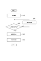
- 4 is a flowchart illustrating processing performed by a control unit when the hydrogen production apparatus is started. It is a system configuration diagram showing a hydrogen production device according to a modification.
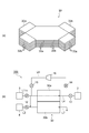
- (A) is a perspective view showing a reforming unit of a hydrogen production device according to a modification, and (b) is a system configuration diagram showing a hydrogen production device according to a modification.
- FIG. 1 is a system configuration diagram showing a hydrogen production apparatus according to one embodiment of the present invention.
- the hydrogen production apparatus 100 shown in FIG. 1 can be used for a mobile object or a stationary fuel cell, for example.
- the hydrogen production device 100 produces hydrogen and supplies the hydrogen to the hydrogen utilization unit 2.
- the hydrogen production device 100 includes a reforming unit 1, a fuel supply unit 3, an oxygen supply unit 4, and a control unit 50.
- the reforming section 1 generates a reformed gas containing hydrogen from ammonia gas as a reforming raw material.
- the reforming section 1 includes a combustion layer 21 and a reforming layer 22.
- the combustion layer 21 generates heat by burning ammonia gas.
- the reforming layer 22 is provided downstream of the combustion layer 21 and reforms ammonia gas to generate reformed gas.
- the combustion layer 21 generates heat by burning ammonia gas.
- the reforming section 1 is an autothermal reforming section that internally generates heat and reforms ammonia gas by an endothermic reaction using the generated heat to generate hydrogen.
- the combustion layer 21 heat is generated by oxidizing ammonia.
- the combustion layer 21 is provided inside the container of the reforming section 1.
- the combustion layer 21 includes a combustion catalyst such as platinum (Pt) or rhodium (Rh).
- a combustion catalyst such as platinum (Pt) or rhodium (Rh).
- Pt platinum
- Rh rhodium
- the reforming section 1 may include a heater. The heater generates heat so that heating in the combustion layer 21 can be started immediately before the combustion of the combustion layer 21 starts. When the exothermic reaction in the combustion layer 21 has reached a steady state, the heater may be stopped.
- the reforming layer 22 is provided in a portion on the downstream side of the combustion layer 21 in the inside of the reforming section 1.
- the reforming layer 22 includes a reforming catalyst such as ruthenium (Ru) or rhodium (Rh).
- the ammonia introduced into the reforming layer 22 is decomposed into hydrogen and nitrogen by the heat generated in the combustion layer 21 and the reforming catalyst. More specifically, as shown in the following equation, a decomposition reaction of ammonia occurs (endothermic reaction), and a reformed gas rich in hydrogen is generated.
- the fuel supply unit 3 supplies the reforming unit 1 with ammonia gas as a fuel.
- the fuel supply unit 3 includes, for example, a storage unit that stores ammonia gas, and an air supply unit that feeds the ammonia gas in the storage unit.
- the oxygen supply unit 4 supplies oxygen to the reforming unit 1.
- the oxygen supply unit 4 includes, for example, a storage unit that stores oxygen, and an air supply unit that supplies oxygen in the storage unit.
- the oxygen supply unit 4 may supply a gas containing oxygen, for example, air.
- the hydrogen utilization unit 2 is provided downstream of the reforming unit 1 and utilizes the hydrogen generated by the reforming unit 1.
- Examples of the hydrogen utilization unit 2 include a fuel cell that generates power using hydrogen, an engine that is driven using hydrogen, and other devices such as a burner heater.
- the hydrogen production apparatus 100 includes a line L1 (second flow path), a line L2 (second flow path), a line L3 (second flow path), a line L4 (first flow path), and a circulation line L5. , Is provided.
- the line L1 is connected to the fuel supply unit 3 and allows the ammonia gas supplied from the fuel supply unit 3 to flow.
- the line L2 is connected to the oxygen supply unit 4 and allows the oxygen supplied from the oxygen supply unit 4 to flow.
- the line L3 is connected to a portion where the line L1 and the line L2 join, and is connected to an upstream end of the reforming unit 1.
- the line L ⁇ b> 4 is connected to the downstream end of the reforming unit 1 and is connected to the hydrogen utilization unit 2.
- the circulation line L5 is connected to a portion of the line L4 upstream of the switching valve 13 and a line L3 upstream of the reforming unit 1.
- the hydrogen production apparatus 100 includes switching valves 11, 12, 13, 14, and 15 and an air supply unit 16.
- the switching valves 11, 12, 13, 14, 15 switch between opening and closing on each line.
- the switching valve 11 is provided in the line L ⁇ b> 1 and switches between supply and stop of the ammonia gas from the fuel supply unit 3.
- the switching valve 12 is provided in the line L2, and switches between supply and stop of oxygen from the oxygen supply unit 4.
- the switching valve 14 is provided near the connection between the circulation line L5 and the line L4.
- the switching valve 15 is provided near the connection of the circulation line L5 with the line L3.
- the switching valves 14 and 15 switch between circulating and stopping the gas to the circulation line L5.
- the switching valve 13 (blocking unit) is provided in the line L4 on the downstream side of the reforming unit 1 and blocks the flow of gas from the reforming unit 1. Further, the switching valve 13 shuts off the gas flowing through the line L4 from the start of the hydrogen production apparatus 100 until the reforming layer 22 of the reforming section 1 is activated.
- the switching valve 13 opens the line L4 so that the gas in the line L4 flows to the hydrogen utilizing section 2.
- the state in which the reforming layer 22 of the reforming section 1 is activated means that the reforming reaction in the reforming layer 22 proceeds, and the unreacted reforming raw material contained in the gas flowing out of the reforming layer 22 is discharged. , Is less than the predetermined amount.
- the hydrogen production apparatus 100 As shown in FIG. 1, when the ammonia contained in the gas flowing out of the reforming layer 22 has a concentration of 1% or less, it can be said that the reforming unit 1 has been activated.
- the reference value that can be said to be activated is appropriately changed depending on the configuration of the hydrogen production apparatus 100 and the like, it is not particularly limited and can be arbitrarily set at the time of production.
- the hydrogen production apparatus 100 includes temperature detection units 20A, 20B, 20C and a composition detection unit 20D.
- the temperature detecting section 20A is provided in a space between the combustion layer 21 and the reforming layer 22 in the reforming section 1, and detects a temperature at the position.
- the temperature detection unit 20B is provided in the modified layer 22, and detects a temperature at the position.
- the temperature detecting section 20C is provided in a space downstream of the reforming layer 22 in the reforming section 1 and detects a temperature at the position.
- the temperature detectors 20A, 20B, and 20C are configured by temperature sensors.
- the composition detector 20D detects the composition of the gas flowing out of the reformed layer 22.
- the composition detector 20D can detect how much hydrogen, unreacted ammonia and other substances are contained in the gas.
- the composition detection unit 20D is configured by a composition sensor.
- the control unit (blocking unit) 50 controls the operation of the entire hydrogen production apparatus 100.
- the control unit 50 includes a processor, a memory, a storage, a communication interface, and a user interface.
- the processor is an arithmetic unit such as a CPU (Central Processing Unit).
- the memory is a storage medium such as a ROM (Read Only Memory) and a RAM (Random Access Memory).
- the storage is a storage medium such as an HDD (Hard Disk Drive).
- the communication interface is a communication device that implements data communication.
- the user interface is an output device such as a liquid crystal or a speaker, and an input device such as a keyboard, a touch panel, or a microphone.
- the processor controls a memory, a storage, a communication interface, and a user interface, and realizes various functions.
- the control unit 50 implements various functions by, for example, loading a program stored in the ROM into the RAM and executing the program loaded into the RAM by the CPU.
- the control unit 50 is electrically connected to the temperature detection units 20A, 20B, 20C and the composition detection unit 20D, and can obtain a detection result.
- the control unit 50 is electrically connected to the switching valves 11, 12, 13, 14, 15 and the air supply unit 16, and can control these operations.
- the control unit 50 controls the switching valve 13 to be closed until the reforming layer 22 of the reforming unit 1 is activated after the start of the hydrogen production apparatus 100, and shuts off the gas flowing through the line L4. At this time, the control unit 50 circulates the gas from the reforming unit 1 through the circulation line L5 by opening the switching valves 14 and 15 and operating the air supply unit 16.
- the control unit 50 opens the switching valve 13 at the timing when the reforming layer 22 of the reforming unit 1 is activated, and causes the gas to flow to the hydrogen utilization unit 2 via the line L4.
- the control unit 50 may use the detection results of the temperature detection units 20A, 20B, and 20C to determine that the reforming layer 22 of the reforming unit 1 has been activated. That is, the control unit 50 releases the cutoff of the gas flow by the switching valve 13 based on the detection results of the temperature detection units 20A, 20B, and 20C.
- the control unit 50 may determine that the reformed layer 22 has been activated when the temperatures detected by the temperature detection units 20A, 20B, and 20C reach a preset threshold.
- the control unit 50 may use any two of the temperature detection units 20A, 20B, and 20C, or only one detection result. In this case, the temperature detection unit not used for detection may be omitted.
- the temperature detectors 20A and 20C are easier to install than the temperature detector 20B inside the modified layer 22. Since the temperature detector 20B is provided inside the modified layer 22, it can directly detect the temperature of the modified layer 22.
- the control unit 50 releases the cutoff of the gas flow by the switching valve 13 based on the detection result of the composition detection unit 20D. For example, when the amount of unreacted ammonia according to the detection result detected by the composition detection unit 20D becomes equal to or less than a predetermined threshold, it may be determined that the reformed layer 22 has been activated. In addition, the control unit 50 may determine that the reformed layer 22 has been activated when the elapsed time reaches a predetermined threshold after the hydrogen production apparatus 100 is started. Although the temperature, the composition, and the time are shown as the determination conditions, the control unit 50 may make the determination based on at least one of the determination conditions. In addition, the threshold value in each determination condition may be appropriately set by a preliminary experiment or the like.
- FIG. 2 is a flowchart showing the processing contents of the control unit when starting up the hydrogen production apparatus.
- the control unit 50 starts the operation of the hydrogen production apparatus 100 (Step S10). At this time, the control unit 50 supplies ammonium gas and oxygen to the reforming unit 1 by opening the switching valves 11 and 12. The control unit 50 closes the switching valve 13 to shut off the gas from the reforming unit 1 at the line L4. Further, the control unit 50 opens the switching valves 14 and 15, activates the air supply unit 16, and circulates the gas from the reforming unit 1 through the circulation line L ⁇ b> 5 and the reforming unit 1.
- the control unit 50 determines whether or not the reforming unit 1 has been activated (Step S20). In S20, when the control unit 50 determines that the reforming unit 1 is not activated, the control unit 50 continues the circulation of the gas using the circulation line L5 (step S30). On the other hand, if the control unit 50 determines that the reforming unit 1 has been activated, the control unit 50 stops gas circulation using the circulation line L5 (step S40). At this time, the control unit 50 stops the air supply unit 16. Further, the control unit 50 opens the switching valve 13 and supplies the gas from the reforming unit 1 to the hydrogen utilizing unit 2. Thus, the processing shown in FIG. 2 is completed, and the reforming in the reforming unit 1 is continued.
- This hydrogen production apparatus 100 is provided in the line L4 on the downstream side of the reforming section 1 and includes a switching valve 13 that shuts off the gas flow. Further, the switching valve 13 shuts off the gas flowing through the line L4 from the start of the hydrogen production apparatus 100 until the reforming unit 1 is activated. Accordingly, in a state before the reforming unit 1 is activated, the switching valve 13 blocks the gas flowing through the line L4, thereby suppressing the gas from flowing to the downstream side of the hydrogen production apparatus 100. be able to. That is, since the reforming section 1 is not activated, even if the gas flowing out of the reforming section 1 contains the unreacted reforming raw material, the gas can be shut off by the switching valve 13. As described above, it is possible to suppress the unreacted reforming raw material from flowing downstream of the hydrogen production apparatus 100.
- the gas discharged from the reforming section 1 contains unreacted reforming raw material
- the gas is supplied again to the reforming section 1 via the line L4, the circulation line L5, and the line L3. . Therefore, the unreacted reforming raw material can be reformed in the reforming section 1 again.
- the reforming section 1 includes a combustion layer 21 that generates heat by burning ammonia gas, and a reforming layer 22 that is provided downstream of the combustion layer 21 and reforms ammonia gas to generate reformed gas. Prepare.
- the reforming unit 1 having such a configuration, since the heat generated in the combustion layer 21 is used in the downstream reforming layer 22, the activation of the reforming unit 1 is quickened. For example, when the hydrogen production apparatus 100 is mounted on a car or the like, the frequency of starting and stopping is greater than that of a fixed-type apparatus such as a hydrogen station.
- the temperature control unit 13 includes temperature detection units 20A, 20B, and 20C that detect the temperature of the reforming unit 1.
- the switching valve 13 releases the interruption of the gas flow based on the detection results of the temperature detection units 20A, 20B, and 20C. By using the temperature of the reforming section 1, the timing for releasing the cutoff can be easily determined.
- the present invention is not limited to the above embodiment.
- the hydrogen production apparatus 200 may include a discharge unit 25 that is provided upstream of the switching valve 13 in the line L4 and that detoxifies and shuts off the gas shut off by the switching valve 13.
- the discharge section 25 is provided on a discharge line L6 connected to a portion of the line L4 upstream of the switching valve 13.
- the tip of the discharge line L6 is open to the atmosphere. Therefore, the gas flowing out of the reforming section 1 is rendered harmless in the discharge section 25 and then discharged to the atmosphere from the discharge line L6.
- the discharge unit 25 has, for example, a catalyst for decomposing unreacted ammonia into nitrogen and water.
- the discharge unit 25 has a function of adding and supplying air (oxygen) as necessary.
- the structure of the reforming section is not limited to the autothermal reforming section as in the above embodiment.
- a heat exchange type reforming section 30 as shown in FIG. 4 may be employed.
- the reforming section 30 includes a plurality of reforming layers 30a including a reforming catalyst for decomposing ammonia into hydrogen, a plurality of combustion layers 30b including a combustion catalyst for burning ammonia, have.
- the reforming layer 30a reforms the ammonia gas from the gas inlet 32a and causes the reformed gas to flow out from the gas outlet 33a.
- the combustion layer 30b combusts ammonia gas and oxygen from the gas inlet 32b, and causes exhaust gas to flow out from the gas outlet 33b.
- the reforming layer 30a and the combustion layer 30b are alternately stacked in a plurality of stages. With such a configuration, the reforming layer 30a can perform reforming using heat generated in the combustion layer 30b. As shown in FIG. 4B, the fuel supply unit 3 supplies ammonia gas to the reforming layer 30a and the combustion layer 30b. The oxygen supply unit 4 supplies oxygen to the combustion layer 30b.
- Other configurations of the hydrogen production apparatus 300 are the same as those of the hydrogen production apparatus 100 shown in FIG.
- a configuration may be adopted in which the heating mechanism for heating the ammonia gas and the reforming section for reforming the ammonia gas are independent from each other.
Landscapes
- Chemical & Material Sciences (AREA)
- Engineering & Computer Science (AREA)
- General Chemical & Material Sciences (AREA)
- Organic Chemistry (AREA)
- Sustainable Energy (AREA)
- Manufacturing & Machinery (AREA)
- Chemical Kinetics & Catalysis (AREA)
- Electrochemistry (AREA)
- Life Sciences & Earth Sciences (AREA)
- Sustainable Development (AREA)
- Health & Medical Sciences (AREA)
- Combustion & Propulsion (AREA)
- Inorganic Chemistry (AREA)
- General Health & Medical Sciences (AREA)
- Fuel Cell (AREA)
- Hydrogen, Water And Hydrids (AREA)
Abstract
水素製造装置(100)は、改質部(1)の下流側のライン(L4)に設けられ、ガスの流れを遮断する切替弁(13)を備える。また、切替弁(13)は、水素製造装置(100)の起動後から改質部(1)が活性化されるまで、ライン(L4)を流れるガスを遮断する。これにより、改質部(1)が活性化される前の状態においては、切替弁(13)は、ライン(L4)を流れるガスを遮断することで、当該ガスが水素製造装置(100)の下流側へ流れることを抑制することができる。すなわち、改質部(1)が活性化していないことによって、改質部(1)から流出するガスに未反応の改質原料が含まれていたとしても、当該ガスを切替弁(13)で遮断できる。
Description
本発明は、水素製造装置に関する。
従来の水素製造装置として、例えば特許文献1に記載されている技術が知られている。特許文献1に記載の水素製造装置は、改質原料を改質することで水素を含有する改質ガスを生成する改質部を有している。改質部で生成された水素は、改質部の下流側に設けられたエンジンなどの水素利用部へ供給される。
ところで、上述のような水素製造装置においては、改質部は、水素製造装置の起動時から、改質触媒が所望の性能を発揮するように活性化されるまでの間に、一定の時間がかかる。従って、改質部が活性化する前には、未反応の改質原料が改質部から流出されるガスに含まれる場合がある。すなわち、未反応の改質原料が、水素製造装置の下流側に流れ、水素利用部に流入する場合がある。
本発明は、未反応の改質原料が水素製造装置の下流側へ流れることを抑制できる水素製造装置を提供することを目的とする。
本発明の一側面に係る水素製造装置は、水素を製造する水素製造装置であって、改質原料であるアンモニアガスから水素を含有する改質ガスを生成する改質部と、改質部の下流側の第1流路に設けられ、ガスの流れを遮断する遮断部と、を備え、遮断部は、水素製造装置の起動後から改質部が活性化されるまで、第1流路を流れるガスを遮断する。
この水素製造装置は、改質部の下流側の第1流路に設けられ、ガスの流れを遮断する遮断部を備える。また、遮断部は、水素製造装置の起動後から改質部が活性化されるまで、第1流路を流れるガスを遮断する。これにより、改質部が活性化される前の状態においては、遮断部は、第1流路を流れるガスを遮断することで、当該ガスが水素製造装置の下流側へ流れることを抑制することができる。すなわち、改質部が活性化していないことによって、改質部から流出するガスに未反応の改質原料が含まれていたとしても、当該ガスを遮断部で遮断できる。以上により、未反応の改質原料が水素製造装置の下流側へ流れることを抑制できる。
第1流路の遮断部よりも上流側の部分と、改質部の上流側の第2流路とに接続される循環ラインと、遮断部で遮断されたガスを循環ラインを介して第1流路から第2流路へ送る送気部と、を備えてよい。この場合、改質部から流出されるガスに未反応の改質原料が含まれていても、当該ガスが第1流路、循環ガス及び第2流路を介して改質部へ再び供給される。よって、未反応の改質原料を改質部で再度改質することができる。
第1流路の遮断部よりも上流側に設けられ、遮断部で遮断されたガスを無害化して排出する排出部を備えてよい。これにより、改質部から流出されるガスに未反応の改質原料が含まれていても、排出部で無害化して排出することができる。
改質部は、アンモニアガスを燃焼させることで発熱する燃焼層と、燃焼層の下流側に設けられ、アンモニアガスを改質して改質ガスを生成する改質層と、を備えてよい。このような構成を有する改質部は、燃焼層で発生した熱が下流側の改質層で用いられるため、改質部の活性化が早くなる。
改質部の温度を検出する温度検出部を備え、遮断部は、温度検出部の検出結果に基づいてガスの流れの遮断を解除してよい。改質部の温度を用いることで遮断を解除するタイミングを容易に判定することができる。
本発明によれば、未反応の改質原料が水素製造装置の下流側へ流れることを抑制できる水素製造装置を提供できる。
以下、図面を参照して種々の実施形態について詳細に説明する。なお、各図面において同一又は相当の部分に対しては同一の符号を付し、重複する説明を省略する。
図1は、本発明の一実施形態に係る水素製造装置を示すシステム構成図である。図1に示される水素製造装置100は、例えば移動体又は定置式の燃料電池に用いられ得る。水素製造装置100は、水素を製造して水素利用部2へ水素を供給する。水素製造装置100は、改質部1と、燃料供給部3と、酸素供給部4と、制御部50と、を備える。
改質部1は、改質原料であるアンモニアガスから水素を含有する改質ガスを生成する。改質部1は、燃焼層21と改質層22とを備える。燃焼層21は、アンモニアガスを燃焼させることで発熱する。改質層22は、燃焼層21の下流側に設けられ、アンモニアガスを改質して改質ガスを生成する。燃焼層21は、アンモニアガスを燃焼させることで発熱する。このように、改質部1は、内部で発熱を行い、発生した熱を用いて吸熱反応によってアンモニアガスの改質を行って水素を生成するオートサーマル式の改質部である。
燃焼層21では、アンモニアを酸化させることで熱を発生させる。燃焼層21は、改質部1の容器の内部に設けられる。燃焼層21は、例えば白金(Pt)又はロジウム(Rh)等の燃焼触媒を備えている。燃焼層21では、燃焼触媒を用いることで、下記の式のように、一部のアンモニアと空気中の酸素とが化学反応し、そのアンモニアの酸化反応により熱が発生する(発熱反応)。この反応により、窒素、及び水を含む流出ガスが生成される。このような発熱反応により、改質層22へ供給されるアンモニアガスが加熱される。なお、改質部1は、ヒータを備えていてよい。当該ヒータは、燃焼層21の燃焼が開始するまでの間に、当該燃焼層21での加熱を速やかに開始できるように熱を発生する。燃焼層21での発熱反応が定常状態となったら、ヒータは停止してよい。
NH3+3/4O2→1/2N2+3/2H2O
NH3+3/4O2→1/2N2+3/2H2O
改質層22は、改質部1の内部のうち、燃焼層21よりも下流側の部分に設けられる。改質層22は、例えばルテニウム(Ru)又はロジウム(Rh)等の改質触媒を備えている。改質層22に導入されたアンモニアは、燃焼層21で発生した熱及び改質触媒によって水素及び窒素に分解される。より具体的には、下記の式のように、アンモニアの分解反応が起こり(吸熱反応)、水素がリッチな状態の改質ガスが生成される。
NH3→3/2H2+1/2N2
NH3→3/2H2+1/2N2
燃料供給部3は、改質部1に対して燃料であるアンモニアガスを供給する。燃料供給部3は、例えば、アンモニアガスを貯留する貯留部と、貯留部のアンモニアガスを送気する送気部と、を備える。酸素供給部4は、改質部1に対して酸素を供給する。酸素供給部4は、例えば、酸素を貯留する貯留部と、貯留部の酸素を送気する送気部と、を備える。なお、酸素供給部4は酸素を含むガス、例えば空気を供給するものであってもよい。
水素利用部2は、改質部1の下流側に設けられ、改質部1で生成された水素を利用する部分である。水素利用部2としては、水素を用いて発電を行う燃料電池、水素を用いて駆動するエンジン、その他、バーナー加熱器などの機器が挙げられる。
水素製造装置100は、ラインL1(第2流路)と、ラインL2(第2流路)と、ラインL3(第2流路)と、ラインL4(第1流路)と、循環ラインL5と、を備える。ラインL1は、燃料供給部3に接続され、当該燃料供給部3から供給されるアンモニアガスを流通させる。ラインL2は、酸素供給部4に接続され、当該酸素供給部4から供給される酸素を流通させる。ラインL3は、ラインL1とラインL2とが合流する部分に接続され、改質部1の上流側の端部に接続される。ラインL4は、改質部1の下流側の端部に接続され、水素利用部2に接続される。循環ラインL5は、ラインL4の切替弁13よりも上流側の部分と、改質部1の上流側のラインL3とに接続される。
水素製造装置100は、切替弁11,12,13,14,15と、送気部16と、を備える。切替弁11,12,13,14,15は、各ライン上で開・閉を切り替える。切替弁11は、ラインL1に設けられ、燃料供給部3からのアンモニアガスの供給と停止を切り替える。切替弁12は、ラインL2に設けられ、酸素供給部4からの酸素の供給と停止を切り替える。切替弁14は、循環ラインL5のラインL4との接続部付近に設けられる。切替弁15は、循環ラインL5のラインL3との接続部付近に設けられる。切替弁14,15は、循環ラインL5へのガスの循環と停止を切り替える。切替弁13(遮断部)は、改質部1の下流側のラインL4に設けられ、改質部1からのガスの流れを遮断する。また、切替弁13は、水素製造装置100の起動後から改質部1の改質層22が活性化されるまで、ラインL4を流れるガスを遮断する。切替弁13は、改質部1の改質層22が活性化されたら、ラインL4を開放し、ラインL4のガスが水素利用部2に流れるようにする。なお、改質部1の改質層22が活性化した状態とは、改質層22での改質反応が進行し、改質層22から流出するガスに含まれる未反応の改質原料が、所定量以下となっている状態である。例えば、図1に示すような水素製造装置100においては、改質層22から流出するガスに含まれるアンモニアが1%以下の濃度となった場合、改質部1が活性化したといえる。ただし、活性化したと言える基準値は、水素製造装置100の構成などによって適宜変更されるものであるため、特に限定されるものではなく、製造時に任意に設定することができる。
水素製造装置100は、温度検出部20A,20B,20Cと、組成検出部20Dと、を備える。温度検出部20Aは、改質部1内の燃焼層21と改質層22との間の空間に設けられ、当該位置における温度を検出する。温度検出部20Bは、改質層22内に設けられ、当該位置における温度を検出する。温度検出部20Cは、改質部1内の改質層22よりも下流側の空間に設けられ、当該位置における温度を検出する。温度検出部20A,20B,20Cは、温度センサによって構成される。組成検出部20Dは、改質層22から流出するガスの組成を検出する。組成検出部20Dは、ガス中に水素、未反応のアンモニア及びその他の物質がどの程度含まれるかを検出することができる。組成検出部20Dは、組成センサによって構成される。
制御部(遮断部)50は、水素製造装置100全体の動作を制御する。制御部50は、プロセッサ、メモリ、ストレージ、通信インターフェース及びユーザインターフェースを備える。プロセッサは、CPU(Central Processing Unit)などの演算器である。メモリは、ROM(Read Only Memory)やRAM(Random Access Memory)などの記憶媒体である。ストレージは、HDD(Hard Disk Drive)などの記憶媒体である。通信インターフェースは、データ通信を実現する通信機器である。ユーザインターフェースは、液晶やスピーカなどの出力器、及び、キーボードやタッチパネルやマイクなどの入力器である。プロセッサは、メモリ、ストレージ、通信インターフェース及びユーザインターフェースを統括し、各種機能を実現する。制御部50では、例えば、ROMに記憶されているプログラムをRAMにロードし、RAMにロードされたプログラムをCPUで実行することにより各種の機能を実現する。
制御部50は、温度検出部20A,20B,20C及び組成検出部20Dと電気的に接続されており、検出結果を取得することができる。制御部50は、切替弁11,12,13,14,15と、送気部16と電気的に接続されており、これらの動作を制御することができる。制御部50は、水素製造装置100の起動後から改質部1の改質層22が活性化されるまで、切替弁13を閉じるように制御し、ラインL4を流れるガスを遮断する。また、このとき、制御部50は、切替弁14,15を開とし、且つ、送気部16を作動させることで、改質部1からのガスを循環ラインL5で循環させる。制御部50は、改質部1の改質層22が活性化したタイミングで、切替弁13を開とし、ラインL4を介して水素利用部2にガスが流れるようにする。
制御部50が、改質部1の改質層22が活性化したことを判定するために、温度検出部20A,20B,20Cの検出結果を用いてよい。すなわち、制御部50は、温度検出部20A,20B,20Cの検出結果に基づいて切替弁13によるガスの流れの遮断を解除する。制御部50は、温度検出部20A,20B,20Cで検出される温度が、予め設定された閾値に到達したときに、改質層22が活性化したと判定してよい。制御部50は、温度検出部20A,20B,20Cのうちの何れか二つ、又は一つの検出結果だけを用いてもよい。この場合、検出に用いられない温度検出部は省略してよい。なお、温度検出部20A,20Cは、改質層22の内部の温度検出部20Bに比して、設置が容易である。温度検出部20Bは、改質層22の内部に設けられているため、改質層22の温度を直接検出することができる。
また、制御部50は、組成検出部20Dの検出結果に基づいて切替弁13によるガスの流れの遮断を解除する。例えば、組成検出部20Dで検出された検出結果に係る未反応のアンモニアの量が所定の閾値以下となったときに、改質層22が活性化したと判定してよい。その他、制御部50は、水素製造装置100を起動させてから、経過時間が所定の閾値となったときに、改質層22が活性化したと判定してよい。なお、判定条件として、温度、組成、時間を示したが、制御部50は、少なくとも何れか一つの判定条件に基づいて判定してよい。なお、各判定条件における閾値は、事前の実験などによって適宜設定されてよい。
次に、図2を参照して、水素製造装置100の起動時における制御部50の処理内容について説明する。図2は、水素製造装置の起動時における制御部の処理内容を示すフローチャートである。
図2に示すように、制御部50は、水素製造装置100の運転を開始する(ステップS10)。このとき、制御部50は、切替弁11,12を開とすることで、改質部1へアンモニウムガス及び酸素を供給する。また、制御部50は、切替弁13を閉とすることで、改質部1からのガスをラインL4で遮断する。また、制御部50は、切替弁14,15を開とし、送気部16を起動させて、改質部1からのガスを循環ラインL5及び改質部1にて循環させる。
次に、制御部50は、改質部1が活性化したか否かを判定する(ステップS20)。S20において、制御部50によって改質部1が活性化していないと判定された場合、制御部50は、循環ラインL5を用いたガスの循環を継続する(ステップS30)。一方、制御部50によって改質部1が活性化したと判定された場合、制御部50は、循環ラインL5を用いたガスの循環を停止する(ステップS40)。このとき、制御部50は、送気部16を停止させる。また、制御部50は、切替弁13を開として、改質部1からのガスを水素利用部2へ供給する。以上により、図2に示す処理が終了し、改質部1での改質を継続する。
次に、本実施形態に係る水素製造装置100の作用・効果について説明する。
この水素製造装置100は、改質部1の下流側のラインL4に設けられ、ガスの流れを遮断する切替弁13を備える。また、切替弁13は、水素製造装置100の起動後から改質部1が活性化されるまで、ラインL4を流れるガスを遮断する。これにより、改質部1が活性化される前の状態においては、切替弁13は、ラインL4を流れるガスを遮断することで、当該ガスが水素製造装置100の下流側へ流れることを抑制することができる。すなわち、改質部1が活性化していないことによって、改質部1から流出するガスに未反応の改質原料が含まれていたとしても、当該ガスを切替弁13で遮断できる。以上により、未反応の改質原料が水素製造装置100の下流側へ流れることを抑制できる。
ラインL4の切替弁13よりも上流側の部分と、改質部1の上流側のラインL3とに接続される循環ラインL5と、切替弁13で遮断されたガスを循環ラインL5を介してラインL4からラインL3へ送る送気部16と、を備える。この場合、改質部1から流出されるガスに未反応の改質原料が含まれていても、当該ガスがラインL4、循環ラインL5及びラインL3を介して改質部1へ再び供給される。よって、未反応の改質原料を改質部1で再度改質することができる。
改質部1は、アンモニアガスを燃焼させることで発熱する燃焼層21と、燃焼層21の下流側に設けられ、アンモニアガスを改質して改質ガスを生成する改質層22と、を備える。このような構成を有する改質部1は、燃焼層21で発生した熱が下流側の改質層22で用いられるため、改質部1の活性化が早くなる。例えば、水素製造装置100が車などに搭載される場合、起動と停止の頻度が、例えば水素ステーションなどの備え付けタイプの装置よりも多くなる。
改質部1の温度を検出する温度検出部20A,20B,20Cを備え、切替弁13は、温度検出部20A,20B,20Cの検出結果に基づいてガスの流れの遮断を解除する。改質部1の温度を用いることで遮断を解除するタイミングを容易に判定することができる。
本発明は、上述の実施形態に限定されるものではない。
図3に示すように、水素製造装置200は、ラインL4の切替弁13よりも上流側に設けられ、切替弁13で遮断されたガスを無害化して排出する排出部25を備えてよい。排出部25は、ラインL4のうち、切替弁13よりも上流側の部分に接続される排出ラインL6に設けられる。排出ラインL6の先端は大気開放されている。従って、改質部1から流出したガスは、排出部25で無害化された後、排出ラインL6から大気へ排出される。排出部25は、例えば未反応のアンモニアを窒素と水に分解するための触媒などを有している。これにより、改質部1から流出されるガスに未反応の改質原料が含まれていても、排出部25で無害化して排出することができる。例えば、酸化燃焼によりガスを無害化することができる。排出部25は、必要に応じて空気(酸素)を添加供給する機能を有する。
また、改質部の構成は上述の実施形態の様なオートサーマル式の改質部に限定されない。例えば、図4に示すような熱交換型の改質部30が採用されてもよい。図4(a)に示すように、改質部30は、アンモニアを水素に分解する改質触媒を含む複数の改質層30aと、アンモニアを燃焼する燃焼触媒を含む複数の燃焼層30bと、を有している。改質層30aは、ガス流入口32aからのアンモニアガスを改質して、ガス流出口33aから改質ガスを流出させる。燃焼層30bは、ガス流入口32bからのアンモニアガス及び酸素を燃焼させて、排気ガスをガス流出口33bから流出させる。改質層30aと燃焼層30bとが交互に複数段積層される。このような構成により、改質層30aは、燃焼層30bで発生した熱を利用して改質を行うことができる。図4(b)に示すように、燃料供給部3は、改質層30a及び燃焼層30bにアンモニアガスを供給する。また、酸素供給部4は、燃焼層30bに酸素を供給する。水素製造装置300のその他の構成については、図1に示す水素製造装置100と同様である。
その他、アンモニアガスを加熱する加熱機構と、アンモニアガスを改質する改質部とが互いに独立したような構成を採用してもよい。
1,30 改質部
13 切替弁(遮断部)
16 送気部
20A,20B,20C 温度検出部
21 燃焼層
22 改質層
25 排出部
100,200,300 水素製造装置
13 切替弁(遮断部)
16 送気部
20A,20B,20C 温度検出部
21 燃焼層
22 改質層
25 排出部
100,200,300 水素製造装置
Claims (5)
- 水素を製造する水素製造装置であって、
改質原料であるアンモニアガスから水素を含有する改質ガスを生成する改質部と、
前記改質部の下流側の第1流路に設けられ、前記ガスの流れを遮断する遮断部と、を備え、
前記遮断部は、前記水素製造装置の起動後から前記改質部が活性化されるまで、前記第1流路を流れるガスを遮断する、水素製造装置。 - 前記第1流路の前記遮断部よりも上流側の部分と、前記改質部の上流側の第2流路とに接続される循環ラインと、
前記遮断部で遮断された前記ガスを前記循環ラインを介して前記第1流路から前記第2流路へ送る送気部と、を備える、請求項1に記載の水素製造装置。 - 前記第1流路の前記遮断部よりも上流側に設けられ、前記遮断部で遮断された前記ガスを無害化して排出する排出部を備える、請求項1に記載の水素製造装置。
- 前記改質部は、
前記アンモニアガスを燃焼させることで発熱する燃焼層と、
前記燃焼層の下流側に設けられ、前記アンモニアガスを改質して前記改質ガスを生成する改質層と、を備える、請求項1~3の何れか一項に記載の水素製造装置。 - 前記改質部の温度を検出する温度検出部を備え、
前記遮断部は、前記温度検出部の検出結果に基づいて前記ガスの流れの遮断を解除する、請求項1~4の何れか一項に記載の水素製造装置。
Applications Claiming Priority (2)
| Application Number | Priority Date | Filing Date | Title |
|---|---|---|---|
| JP2018-120113 | 2018-06-25 | ||
| JP2018120113A JP2020001939A (ja) | 2018-06-25 | 2018-06-25 | 水素製造装置 |
Publications (1)
| Publication Number | Publication Date |
|---|---|
| WO2020004146A1 true WO2020004146A1 (ja) | 2020-01-02 |
Family
ID=68986563
Family Applications (1)
| Application Number | Title | Priority Date | Filing Date |
|---|---|---|---|
| PCT/JP2019/024105 Ceased WO2020004146A1 (ja) | 2018-06-25 | 2019-06-18 | 水素製造装置 |
Country Status (2)
| Country | Link |
|---|---|
| JP (1) | JP2020001939A (ja) |
| WO (1) | WO2020004146A1 (ja) |
Cited By (2)
| Publication number | Priority date | Publication date | Assignee | Title |
|---|---|---|---|---|
| JPWO2025018410A1 (ja) * | 2023-07-20 | 2025-01-23 | ||
| WO2025150261A1 (ja) * | 2024-01-12 | 2025-07-17 | 三菱化工機株式会社 | アンモニア・水素混合燃料製造装置、燃料供給システム、及び水素の製造方法 |
Families Citing this family (2)
| Publication number | Priority date | Publication date | Assignee | Title |
|---|---|---|---|---|
| JP7076930B2 (ja) * | 2020-07-09 | 2022-05-30 | 中外炉工業株式会社 | アンモニア燃料燃焼装置 |
| US20250144610A1 (en) * | 2023-11-06 | 2025-05-08 | Air Products And Chemicals, Inc. | Apparatus and process for ammonia cracking catalyst activation |
Citations (4)
| Publication number | Priority date | Publication date | Assignee | Title |
|---|---|---|---|---|
| JP2002198081A (ja) * | 2000-12-22 | 2002-07-12 | Honda Motor Co Ltd | 燃料電池用燃料ガス生成装置 |
| JP2006199531A (ja) * | 2005-01-20 | 2006-08-03 | Toyota Motor Corp | 改質装置及び燃料電池システム |
| JP2010282755A (ja) * | 2009-06-02 | 2010-12-16 | Hitachi Zosen Corp | アンモニアを燃料に用いる燃料電池システム |
| JP2018076214A (ja) * | 2016-11-11 | 2018-05-17 | 株式会社豊田自動織機 | 水素生成装置 |
-
2018
- 2018-06-25 JP JP2018120113A patent/JP2020001939A/ja active Pending
-
2019
- 2019-06-18 WO PCT/JP2019/024105 patent/WO2020004146A1/ja not_active Ceased
Patent Citations (4)
| Publication number | Priority date | Publication date | Assignee | Title |
|---|---|---|---|---|
| JP2002198081A (ja) * | 2000-12-22 | 2002-07-12 | Honda Motor Co Ltd | 燃料電池用燃料ガス生成装置 |
| JP2006199531A (ja) * | 2005-01-20 | 2006-08-03 | Toyota Motor Corp | 改質装置及び燃料電池システム |
| JP2010282755A (ja) * | 2009-06-02 | 2010-12-16 | Hitachi Zosen Corp | アンモニアを燃料に用いる燃料電池システム |
| JP2018076214A (ja) * | 2016-11-11 | 2018-05-17 | 株式会社豊田自動織機 | 水素生成装置 |
Cited By (8)
| Publication number | Priority date | Publication date | Assignee | Title |
|---|---|---|---|---|
| JPWO2025018410A1 (ja) * | 2023-07-20 | 2025-01-23 | ||
| WO2025018410A1 (ja) * | 2023-07-20 | 2025-01-23 | 三菱化工機株式会社 | アンモニア・水素混合燃料製造装置、燃料供給システム、及び水素の製造方法 |
| JP7733275B2 (ja) | 2023-07-20 | 2025-09-02 | 三菱化工機株式会社 | アンモニア・水素混合燃料製造装置、燃料供給システム、及び水素の製造方法 |
| WO2025150261A1 (ja) * | 2024-01-12 | 2025-07-17 | 三菱化工機株式会社 | アンモニア・水素混合燃料製造装置、燃料供給システム、及び水素の製造方法 |
| JPWO2025150561A1 (ja) * | 2024-01-12 | 2025-07-17 | ||
| WO2025150561A1 (ja) * | 2024-01-12 | 2025-07-17 | 三菱化工機株式会社 | 反応器、水素の製造装置及び水素の製造方法 |
| JP7756477B1 (ja) * | 2024-01-12 | 2025-10-20 | 三菱化工機株式会社 | アンモニア・水素混合燃料製造装置、燃料供給システム、及び水素の製造方法 |
| JP7833614B2 (ja) | 2024-01-12 | 2026-03-19 | 三菱化工機株式会社 | 反応器、水素の製造装置及び水素の製造方法 |
Also Published As
| Publication number | Publication date |
|---|---|
| JP2020001939A (ja) | 2020-01-09 |
Similar Documents
| Publication | Publication Date | Title |
|---|---|---|
| JP3826770B2 (ja) | 燃料改質システム | |
| JP3885479B2 (ja) | 燃料電池の改質装置 | |
| CN101379646B (zh) | 燃料电池系统 | |
| JP5446184B2 (ja) | 発電システム及び発電システムの制御装置 | |
| JP2020001939A (ja) | 水素製造装置 | |
| JP4354792B2 (ja) | 燃料電池発電装置 | |
| JP2008532920A (ja) | 燃料電池装置用の燃料処理装置及び燃料電池装置用の燃料処理装置の動作方法 | |
| JP2003229149A (ja) | 燃料電池発電システムおよび燃料電池発電方法 | |
| JP5135209B2 (ja) | 水素生成装置、これを備える燃料電池システムおよびその運転方法 | |
| JP2000095504A (ja) | 改質装置 | |
| JP5420636B2 (ja) | 水素生成装置、それを備える燃料電池システム、及び水素生成装置の運転方法 | |
| JP2021017389A (ja) | 改質システム | |
| JP2020070213A (ja) | 改質システム | |
| JP2020087556A (ja) | 燃料電池システム | |
| JP3916485B2 (ja) | 水素含有ガス生成装置の前処理方法 | |
| KR101464064B1 (ko) | 일산화탄소 변성 장치 및 방법 그리고 수소 제조 장치 | |
| JP2004217435A (ja) | 水素含有ガス生成装置の停止方法及び水素含有ガス生成装置 | |
| JP5236554B2 (ja) | 燃料電池システム | |
| JP5886497B2 (ja) | 改質システム | |
| JP4800174B2 (ja) | 改質装置及びその運転方法 | |
| JP2015140285A (ja) | 水素含有ガス生成装置の運転方法及び水素含有ガス生成装置 | |
| JP4713547B2 (ja) | 燃料電池発電システムおよびその運転方法 | |
| JP4175432B2 (ja) | 改質装置及びその運転方法 | |
| JP2006169013A (ja) | 水素生成装置及び燃料電池システム並びにそれらの運転方法 | |
| JP2009078938A (ja) | 脱硫器およびその運転方法、ならびに燃料電池システム |
Legal Events
| Date | Code | Title | Description |
|---|---|---|---|
| 121 | Ep: the epo has been informed by wipo that ep was designated in this application |
Ref document number: 19825847 Country of ref document: EP Kind code of ref document: A1 |
|
| NENP | Non-entry into the national phase |
Ref country code: DE |
|
| 122 | Ep: pct application non-entry in european phase |
Ref document number: 19825847 Country of ref document: EP Kind code of ref document: A1 |