WO2020003433A1 - 靴 - Google Patents
靴 Download PDFInfo
- Publication number
- WO2020003433A1 WO2020003433A1 PCT/JP2018/024556 JP2018024556W WO2020003433A1 WO 2020003433 A1 WO2020003433 A1 WO 2020003433A1 JP 2018024556 W JP2018024556 W JP 2018024556W WO 2020003433 A1 WO2020003433 A1 WO 2020003433A1
- Authority
- WO
- WIPO (PCT)
- Prior art keywords
- outsole
- midsole
- thermoplastic elastomer
- shoe
- matrix
- Prior art date
- Legal status (The legal status is an assumption and is not a legal conclusion. Google has not performed a legal analysis and makes no representation as to the accuracy of the status listed.)
- Ceased
Links
Images






Classifications
-
- A—HUMAN NECESSITIES
- A43—FOOTWEAR
- A43B—CHARACTERISTIC FEATURES OF FOOTWEAR; PARTS OF FOOTWEAR
- A43B13/00—Soles; Sole-and-heel integral units
- A43B13/02—Soles; Sole-and-heel integral units characterised by the material
- A43B13/12—Soles with several layers of different materials
- A43B13/122—Soles with several layers of different materials characterised by the outsole or external layer
-
- A—HUMAN NECESSITIES
- A43—FOOTWEAR
- A43B—CHARACTERISTIC FEATURES OF FOOTWEAR; PARTS OF FOOTWEAR
- A43B13/00—Soles; Sole-and-heel integral units
- A43B13/02—Soles; Sole-and-heel integral units characterised by the material
- A43B13/04—Plastics, rubber or vulcanised fibre
-
- A—HUMAN NECESSITIES
- A43—FOOTWEAR
- A43B—CHARACTERISTIC FEATURES OF FOOTWEAR; PARTS OF FOOTWEAR
- A43B13/00—Soles; Sole-and-heel integral units
- A43B13/02—Soles; Sole-and-heel integral units characterised by the material
- A43B13/12—Soles with several layers of different materials
-
- A—HUMAN NECESSITIES
- A43—FOOTWEAR
- A43B—CHARACTERISTIC FEATURES OF FOOTWEAR; PARTS OF FOOTWEAR
- A43B13/00—Soles; Sole-and-heel integral units
- A43B13/02—Soles; Sole-and-heel integral units characterised by the material
- A43B13/12—Soles with several layers of different materials
- A43B13/125—Soles with several layers of different materials characterised by the midsole or middle layer
-
- A—HUMAN NECESSITIES
- A43—FOOTWEAR
- A43B—CHARACTERISTIC FEATURES OF FOOTWEAR; PARTS OF FOOTWEAR
- A43B13/00—Soles; Sole-and-heel integral units
- A43B13/14—Soles; Sole-and-heel integral units characterised by the constructive form
- A43B13/18—Resilient soles
- A43B13/187—Resiliency achieved by the features of the material, e.g. foam, non liquid materials
-
- B—PERFORMING OPERATIONS; TRANSPORTING
- B32—LAYERED PRODUCTS
- B32B—LAYERED PRODUCTS, i.e. PRODUCTS BUILT-UP OF STRATA OF FLAT OR NON-FLAT, e.g. CELLULAR OR HONEYCOMB, FORM
- B32B27/00—Layered products comprising a layer of synthetic resin
- B32B27/06—Layered products comprising a layer of synthetic resin as the main or only constituent of a layer, which is next to another layer of the same or of a different material
- B32B27/065—Layered products comprising a layer of synthetic resin as the main or only constituent of a layer, which is next to another layer of the same or of a different material of foam
-
- B—PERFORMING OPERATIONS; TRANSPORTING
- B32—LAYERED PRODUCTS
- B32B—LAYERED PRODUCTS, i.e. PRODUCTS BUILT-UP OF STRATA OF FLAT OR NON-FLAT, e.g. CELLULAR OR HONEYCOMB, FORM
- B32B27/00—Layered products comprising a layer of synthetic resin
- B32B27/18—Layered products comprising a layer of synthetic resin characterised by the use of special additives
- B32B27/20—Layered products comprising a layer of synthetic resin characterised by the use of special additives using fillers, pigments, thixotroping agents
-
- B—PERFORMING OPERATIONS; TRANSPORTING
- B32—LAYERED PRODUCTS
- B32B—LAYERED PRODUCTS, i.e. PRODUCTS BUILT-UP OF STRATA OF FLAT OR NON-FLAT, e.g. CELLULAR OR HONEYCOMB, FORM
- B32B27/00—Layered products comprising a layer of synthetic resin
- B32B27/32—Layered products comprising a layer of synthetic resin comprising polyolefins
-
- B—PERFORMING OPERATIONS; TRANSPORTING
- B32—LAYERED PRODUCTS
- B32B—LAYERED PRODUCTS, i.e. PRODUCTS BUILT-UP OF STRATA OF FLAT OR NON-FLAT, e.g. CELLULAR OR HONEYCOMB, FORM
- B32B3/00—Layered products comprising a layer with external or internal discontinuities or unevennesses, or a layer of non-planar shape; Layered products comprising a layer having particular features of form
- B32B3/26—Layered products comprising a layer with external or internal discontinuities or unevennesses, or a layer of non-planar shape; Layered products comprising a layer having particular features of form characterised by a particular shape of the outline of the cross-section of a continuous layer; characterised by a layer with cavities or internal voids ; characterised by an apertured layer
- B32B3/266—Layered products comprising a layer with external or internal discontinuities or unevennesses, or a layer of non-planar shape; Layered products comprising a layer having particular features of form characterised by a particular shape of the outline of the cross-section of a continuous layer; characterised by a layer with cavities or internal voids ; characterised by an apertured layer characterised by an apertured layer, the apertures going through the whole thickness of the layer, e.g. expanded metal, perforated layer, slit layer regular cells B32B3/12
-
- B—PERFORMING OPERATIONS; TRANSPORTING
- B32—LAYERED PRODUCTS
- B32B—LAYERED PRODUCTS, i.e. PRODUCTS BUILT-UP OF STRATA OF FLAT OR NON-FLAT, e.g. CELLULAR OR HONEYCOMB, FORM
- B32B3/00—Layered products comprising a layer with external or internal discontinuities or unevennesses, or a layer of non-planar shape; Layered products comprising a layer having particular features of form
- B32B3/26—Layered products comprising a layer with external or internal discontinuities or unevennesses, or a layer of non-planar shape; Layered products comprising a layer having particular features of form characterised by a particular shape of the outline of the cross-section of a continuous layer; characterised by a layer with cavities or internal voids ; characterised by an apertured layer
- B32B3/30—Layered products comprising a layer with external or internal discontinuities or unevennesses, or a layer of non-planar shape; Layered products comprising a layer having particular features of form characterised by a particular shape of the outline of the cross-section of a continuous layer; characterised by a layer with cavities or internal voids ; characterised by an apertured layer characterised by a layer formed with recesses or projections, e.g. hollows, grooves, protuberances, ribs
-
- B—PERFORMING OPERATIONS; TRANSPORTING
- B32—LAYERED PRODUCTS
- B32B—LAYERED PRODUCTS, i.e. PRODUCTS BUILT-UP OF STRATA OF FLAT OR NON-FLAT, e.g. CELLULAR OR HONEYCOMB, FORM
- B32B5/00—Layered products characterised by the non- homogeneity or physical structure, i.e. comprising a fibrous, filamentary, particulate or foam layer; Layered products characterised by having a layer differing constitutionally or physically in different parts
- B32B5/18—Layered products characterised by the non- homogeneity or physical structure, i.e. comprising a fibrous, filamentary, particulate or foam layer; Layered products characterised by having a layer differing constitutionally or physically in different parts characterised by features of a layer of foamed material
-
- B—PERFORMING OPERATIONS; TRANSPORTING
- B32—LAYERED PRODUCTS
- B32B—LAYERED PRODUCTS, i.e. PRODUCTS BUILT-UP OF STRATA OF FLAT OR NON-FLAT, e.g. CELLULAR OR HONEYCOMB, FORM
- B32B7/00—Layered products characterised by the relation between layers; Layered products characterised by the relative orientation of features between layers, or by the relative values of a measurable parameter between layers, i.e. products comprising layers having different physical, chemical or physicochemical properties; Layered products characterised by the interconnection of layers
- B32B7/02—Physical, chemical or physicochemical properties
-
- B—PERFORMING OPERATIONS; TRANSPORTING
- B32—LAYERED PRODUCTS
- B32B—LAYERED PRODUCTS, i.e. PRODUCTS BUILT-UP OF STRATA OF FLAT OR NON-FLAT, e.g. CELLULAR OR HONEYCOMB, FORM
- B32B7/00—Layered products characterised by the relation between layers; Layered products characterised by the relative orientation of features between layers, or by the relative values of a measurable parameter between layers, i.e. products comprising layers having different physical, chemical or physicochemical properties; Layered products characterised by the interconnection of layers
- B32B7/02—Physical, chemical or physicochemical properties
- B32B7/027—Thermal properties
-
- B—PERFORMING OPERATIONS; TRANSPORTING
- B32—LAYERED PRODUCTS
- B32B—LAYERED PRODUCTS, i.e. PRODUCTS BUILT-UP OF STRATA OF FLAT OR NON-FLAT, e.g. CELLULAR OR HONEYCOMB, FORM
- B32B2264/00—Composition or properties of particles which form a particulate layer or are present as additives
- B32B2264/02—Synthetic macromolecular particles
- B32B2264/0214—Particles made of materials belonging to B32B27/00
- B32B2264/0221—Thermoplastic elastomer particles
-
- B—PERFORMING OPERATIONS; TRANSPORTING
- B32—LAYERED PRODUCTS
- B32B—LAYERED PRODUCTS, i.e. PRODUCTS BUILT-UP OF STRATA OF FLAT OR NON-FLAT, e.g. CELLULAR OR HONEYCOMB, FORM
- B32B2264/00—Composition or properties of particles which form a particulate layer or are present as additives
- B32B2264/40—Pretreated particles
- B32B2264/403—Pretreated particles coated or encapsulated
-
- B—PERFORMING OPERATIONS; TRANSPORTING
- B32—LAYERED PRODUCTS
- B32B—LAYERED PRODUCTS, i.e. PRODUCTS BUILT-UP OF STRATA OF FLAT OR NON-FLAT, e.g. CELLULAR OR HONEYCOMB, FORM
- B32B2437/00—Clothing
- B32B2437/02—Gloves, shoes
Definitions
- the present invention relates to a shoe, and more particularly, to a shoe including a midsole and an outsole.
- a conventional shoe sole includes a plurality of members such as a midsole and an outsole.
- the midsole is conventionally formed of a polymer foam or the like in order to exert lightness and cushioning properties on the shoe.
- the outsole constitutes a ground contact portion that comes into contact with the ground when a shoe wearer walks, and since it is necessary to have excellent strength, gripping properties, and abrasion resistance, a non-foamed rubber sheet, etc. It is constituted by. 2.
- Patent Document 1 describes a method of manufacturing shoes different from a conventional general manufacturing method.
- the same resin ethylene-vinyl acetate copolymer (EVA)
- EVA ethylene-vinyl acetate copolymer
- Patent Literature 1 describes that the productivity of shoes can be improved by heat-sealing them during molding.
- a molding die that forms one space by connecting a molding space for forming an outsole and a molding space for forming a midsole is used.
- EVA is filled in a molding space for forming an outsole and a molding space for forming a midsole, and hot pressing is performed.
- the EVA for the outsole is required to exhibit high fluidity at the heating temperature during hot pressing in order to form an outsole sufficiently reflecting the shape of the mold.
- the fluidity of the EVA is excessively high, the EVA for the outsole may flow out of the molding space for forming the outsole, and a high-quality product may not be obtained.
- an object of the present invention is to solve such a problem, and an object of the present invention is to provide shoes that can be efficiently manufactured and can easily obtain high-quality products.
- the present invention includes a midsole composed of a polymer foam and an outsole composed of a thermoplastic elastomer, The outsole and the midsole are heat-sealed, A shoe wherein the complex viscosity at 140 ° C. ( ⁇ 140 ) and the complex viscosity at 180 ° C. ( ⁇ 180 ) of the thermoplastic elastomer satisfy both of the following relational expressions (1) and (2). 10 kPa ⁇ s ⁇ ⁇ 140 ⁇ 300 kPa ⁇ s (1) ⁇ 180 ⁇ 100 kPa ⁇ s (2)
- FIG. 1 is a schematic side view illustrating a shoe according to one embodiment.
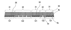
- FIG. 3 is a cross-sectional view taken along line III-III of FIG. 2 (cross-section of a first ground portion).
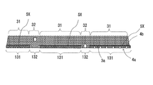
- FIG. 4 is a cross-sectional view taken along line IV-IV of FIG. 2 (cross-section of a second ground portion).
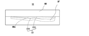
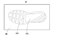
- FIG. 2 is a schematic plan view of a molding die.
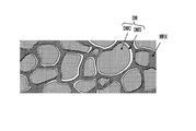
- FIG. 4 is a schematic diagram showing a state of thermoforming using a molding die. The figure which showed typically the state where a thermoplastic elastomer has a micro phase separation structure.
- the figure which shows the evaluation result in an Example (the graph which showed the relationship between the complex viscosity of the thermoplastic elastomer which comprises an outsole, and the filling property to a type
- the figure which shows the evaluation result in an Example (the graph which showed the relationship between the complex viscosity of the thermoplastic elastomer which comprises an outsole, and the flow amount at the time of shaping
- FIG. 1 is a schematic perspective view showing a shoe 1 of the present embodiment, and shows a state where the shoe is grounded when a wearer is walking.
- FIG. 2 shows a state of a lower surface of the shoe 1 (hereinafter, also referred to as “shoe bottom 1a”).
- the shoe 1 of the present embodiment has an upper 2 and members 3 and 4 for soles.
- the shoe 1 has a midsole 3 and an outsole 4 as sole members.
- the direction along the shoe center axis CX connecting the center HC of the heel and the center TC of the toe may be referred to as a length direction X.
- the direction X1 from the heel to the toe may be referred to as forward
- the direction X2 from the toe to the heel may be referred to as rear
- the direction parallel to the horizontal plane HP may be referred to as the width direction Y.
- the width direction Y the direction Y1 toward the first finger side of the foot may be referred to as inward, and the direction Y2 toward the fifth finger side may be referred to as outward.
- the vertical direction Z orthogonal to the horizontal plane HP may be referred to as a thickness direction or a height direction.
- the upward direction Z1 may be referred to as an upward direction
- the downward direction Z2 may be referred to as a downward direction.
- the shoe 1 of the present embodiment includes an outsole 4 at the lowest position.
- the outsole 4 of the present embodiment has a sheet shape, and is arranged at the lowermost part of the shoe 1 such that the thickness direction is the vertical direction Z.
- the shoe 1 includes a midsole 3 between the upper 2 that covers a wearer's foot from above and the outsole 4.
- the midsole 3 of the present embodiment has a flat shape, and is arranged such that the thickness direction thereof is the height direction Z of the shoe.
- the lower surface of the midsole 3 is in contact with the upper surface of the outsole 4, and the upper surface of the midsole 3 is in contact with the upper 2 from below.
- the lower surface of the shoe 1 of the present embodiment is slightly recessed upward at a portion corresponding to the arch of the wearer. This part is provided with a non-ground portion 11 that does not come into contact with the ground when the wearer walks.
- the shoe 1 according to the present embodiment includes the grounding portions 12 and 13 that come into contact with the ground when the wearer walks, before and after the non-grounding portion 11.
- a contact portion 12 on the heel side of the non-contact portion 11 hereinafter, also referred to as “heel contact portion 12”
- a contact portion 13 on the toe side of the non-contact portion 11 hereinafter, “toe contact portion 13”.
- the outsole 4 covers only a part of the midsole 3 from below. That is, as shown in FIGS.
- the midsole 3 is covered with the outsole 4 from the lower side, and the exposed area is not covered with the outsole 4 and is exposed. And an area 32.
- the shoe sole 1a at least one of the forefoot portion and the heel portion, the first regions 121 and 131 where the outsole is exposed, and the second region 122 where the midsole is exposed. , 132 are provided.
- the midsole 3 of the present embodiment is formed of a polymer foam, and it is easy to increase the density of only a specific region in the surface layer. Therefore, the midsole 3 of the present embodiment can exhibit excellent wear resistance even if a part thereof constitutes a grounding portion together with the outsole 4. It is desirable that the first regions 121 and 131 and the second regions 122 and 132 that serve as the grounding portions exhibit excellent gripping and cushioning properties. Therefore, in the exposed region 32 of the midsole 3 in the heel-side grounding portion 12 and the toe-side grounding portion 13 corresponding to the second regions 122 and 132, an uneven surface is formed on the lower surface side of the midsole 3. .
- the midsole 3 has a convex portion protruding downward in the exposed region 32 and a concave portion recessed upward.
- the uneven surface provided on the midsole 3 may be one in which a plurality of protrusions are only scattered on a flat surface, or one in which only a plurality of ridges are provided on a flat surface. Good.
- the uneven surface provided on the midsole 3 may be one in which a plurality of flat surfaces are recessed, or one in which a plurality of grooves are provided in the flat surface. Is also good.
- the shape of the convex portion and the concave shape of the concave portion are not particularly limited, and may be, for example, a cone, a pyramid, a truncated cone, a truncated pyramid, an irregular shape, or the like.
- the shape is not particularly limited also when the convex portion or the concave portion is the convex line or the groove, and the convex line or the groove is, for example, linear, curved, meandering, or spiral. And so on.
- the cross-sectional shapes of the ridges and grooves are not particularly limited.
- the outsole 4 is also formed with irregularities on the lower surface side, and includes a convex portion protruding downward and a concave portion recessed upward.
- each of the heel-side grounding portion 12 and the toe-side grounding portion 13 is provided with an uneven surface so as to exhibit excellent gripping properties, and the first region 121, 131 and the second region 122, 132 Are provided with an uneven surface.
- a convex portion having a height of 1 mm or more (length downward) is formed in the heel side contact portion 12 and the toe side contact portion 13.
- the height of the protrusion is more preferably 1.5 mm or more, and particularly preferably 2 mm or more.
- the height of the convex portion is usually 10 mm or less.
- the aspect ratio which is the ratio (H / W) of the height (H) to the width of the projection (width at the base end: W), is preferably 0.3 or more, and is 0.5 or more. More preferably, it is more preferably 1.0 or more, and particularly preferably 2.0 or more.
- the aspect ratio of the convex portion is usually 10 or less.
- the convex portion of the midsole 3 does not need to be in a state where the position of the distal end portion is aligned with the distal end portion of the convex portion of the outsole 4. At least a part of the convex portion of the midsole 3 has an outsole such that the tip does not contact the ground when the shoe 1 is in a no-load state and comes into contact with the ground when the weight of the wearer is added. 4 may be formed so as to be located above the convex portion.
- the lower surface 3 a of the midsole 3 has an uneven surface in the exposed region 32, while it has a flat surface in the covering region 31.
- the outsole 4 has an uneven surface on the lower surface 4a but no unevenness on the upper surface 4b. That is, in the contact area SX where the upper surface 4b of the outsole 4 and the lower surface 3a of the midsole 3 are in contact with each other in the up-down direction, the respective surfaces are flat.
- the outsole 4 and the midsole 3 of the present embodiment are thermally fused in the contact area SX.
- the midsole 3 in the present embodiment is made of a polymer foam.
- the outsole 4 in the present embodiment is made of a thermoplastic elastomer.
- the midsole 3 and the outsole are formed simultaneously using a single mold as described in detail later.
- the midsole 3 and the outsole are integrated by heat fusion at the contact area SX during this molding.
- a method of simultaneously forming the midsole 3 and the outsole 4 will be described.
- a preform for forming the midsole 3 hereinafter also referred to as a “first preform”
- the outsole 4 Preparing a preformed body (hereinafter, also referred to as a “second preformed body”) for forming the first preformed body, and pressing the first preformed body and the second preformed body in a heated state to form a preformed body.
- a thermoforming step of thermally fusing them between the preparation step and the thermoforming step, a binder for promoting thermal fusion in the thermoforming step is provided on at least one surface of the first preform and the second preform.
- a pretreatment step of applying may be performed.
- a foam slightly larger than the midsole 3 is produced as the first preform for the midsole, and no irregular surface is formed on both surfaces as the second preform for the outsole.
- a flat sheet body can be manufactured.
- a foam slightly larger than the first preform is produced, and an extra portion is removed from the foam to finish the first preform.
- the foam can be produced, for example, by foaming a polymer composition containing a foaming agent inside a mold having a molding space corresponding to the shape of the foam.
- the foam may be subjected to cutting or the like. By performing the cutting process, a first preform having a cut surface of bubbles on the surface can be obtained, and a first preform having an anchor effect easily exerted can be obtained.
- the second preform manufactured in the preparation step may be a sheet body whose shape in plan view corresponds to the outsole 4.
- a flat raw material sheet having a larger area and a uniform thickness than the second preform is prepared, and an extra portion of the raw material sheet is removed. What is necessary is just to implement two preforms.
- the raw material sheet can be produced by, for example, injection molding a thermoplastic elastomer for constituting the outsole 4.
- a blade such as a cutter knife or scissors can be used to remove an unnecessary portion from the raw material sheet.
- a punching process using a Thomson blade or the like may be performed.
- the shoes 1 usually require a lineup of products of a plurality of sizes even if they have the same design.
- the production cost can be reduced. That is, the production cost of shoes is reduced by preparing one injection molding die capable of producing a material sheet having a larger area than the second preform, which is the largest necessary for producing shoes 1 having different sizes. Can be achieved. Even if the second preform is produced by punching from a raw material sheet, it is only necessary to prepare a plurality of simple dies such as a Thomson blade die, so that the production cost is greatly reduced as compared with the case of preparing a plurality of injection molding dies. Can be done.
- the uneven surface of the midsole 3 and the outsole 4 can be formed in the thermoforming step, and the lower surfaces of the first preformed body and the second preformed body are the midsole. It is not necessary to have an uneven surface such as that provided on the lower surface 3a of the base 3 or the lower surface 4a of the outsole 4, and it can be a flat surface. That is, in the present embodiment, even when the first preform and the second preform are manufactured using a molding die, the effect that the structure of the molding die can be made relatively simple can be obtained. Can be demonstrated.
- the pretreatment step can be performed by a method of applying the binder to a first preform or a second preform.
- the application of the binder can be performed using a general tool such as a brush or a spray.
- the application of the binder may be performed only on a part of the surface of the first preformed body or the second preformed body, or may be performed on the entire surface.
- the binder may be applied at the time of the raw material sheet. It is preferable that the application of the binder is performed at least over the entire contact area SX.
- a molding die M as shown in FIGS. 5A, 5B, and 5C is used.
- the mold M is composed of a pair of molds having mold mating surfaces that come into contact with each other when the mold is closed.
- the molding die M has a male die MM and a female die MF as a pair of the die.
- each of the male MM and the female MF has a plate shape.
- the molding die M is configured so that a molding space CV in a closed state can be formed inside by overlapping the male die MM and the female die MF.
- the molding die M is configured such that the molding space CV corresponding to the shape in a state where the midsole 3 and the outsole 4 are integrated can be formed inside when the mold is closed.
- the molding space CV includes a first space portion CV3 corresponding to the shape of the midsole 3 and a second space portion CV4 corresponding to the shape of the outsole 4.
- the female mold MF has a molding recess MFa that is open on the side having the mold mating surface and that is recessed in the thickness direction of the female mold MF.
- the molding recess MFa is formed such that the thickness direction of the midsole 3 and the outsole 4 is the depth direction.
- the male mold MM includes a molding protrusion MMa that protrudes from the mold matching surface and can enter the molding recess MFa of the female mold MF. Then, when the female mold MF and the male mold MM are superimposed, the molding die M is in a state where the molding convex portion MMa has entered halfway in the depth direction of the molding concave portion MFa, and the molding space CV is formed. It is configured to be formed inside.
- the molding die M is configured such that the molding space CV can be defined by the inner wall surface at the bottom of the molding concave portion MFa and the lower surface of the molding convex portion MMa.
- the bottom surface of the molding surface (inner wall surface) of the female mold MF is formed with irregularities having a shape opposite to the irregularities provided on the shoe sole 1a.
- the female mold MF is provided with irregularities on its bottom surface for making the lower surfaces of the first preform and the second preform into a predetermined shape.
- thermoforming step of simultaneously molding the midsole 3 and the outsole 4 in the present embodiment as shown in FIG. 6, for example, the first molded body 3x and the second molded body 4x are housed in the molding space CV.
- a method in which the formed mold M is heated and pressed by a hot press having a pair of hot plates HB can be employed.
- the second mold 4x is set in the second space CV4 and the first mold 3x is set in the first space CV3. It is possible to adopt a method in which the mold is heated with the hot platen HB and the female mold MF and the female mold MM are pressed in the approaching direction.
- the mold M is heated to a high temperature so that the first molded body 3x and the second molded body 4x are easily deformed. This is more advantageous in obtaining a molded product in which the shape of the molding space CV is faithfully reflected.
- the heating temperature of the mold M is increased, excessive fluidity is exerted on the second molded body 4x, and the thermoplastic elastomer constituting the second molded body 4x overflows from the second space CV4. May occur. That is, when the heating temperature of the molding die M is increased, the overall shape of the molded product can be high in accuracy, but the outer accuracy of the midsole and the outsole constituting the molded product is low. There is a risk.
- thermoplastic elastomer as a material for forming the outsole 4, it is easy to obtain a molded product having a high accuracy in the overall shape and the individual shapes of the midsole and the outsole. Has become.
- the thermoplastic elastomer constituting the outsole 4 satisfies both of the following relational expressions (1) and (2) when measuring the complex viscosity. 10 kPa ⁇ s ⁇ ⁇ 140 ⁇ 300 kPa ⁇ s (1) ⁇ 180 ⁇ 100 kPa ⁇ s (2)
- ⁇ 140 in the relational expression (1) means the complex viscosity (kPa ⁇ s) at 140 ° C. of the thermoplastic elastomer
- ⁇ 180 ” in the relational expression (2) means the thermoplastic elastomer. Of 180 ° C. (kPa ⁇ s).
- the complex viscosity ( ⁇ 140 ) at 140 ° C. of the thermoplastic elastomer is 10 kPa ⁇ s or more, even when the temperature of the mold M in the thermoforming step is increased, the excessive fluidity is prevented from being exhibited. Thus, the possibility of overflow from the second space portion CV4 can be reduced. Therefore, in the present embodiment, it is possible to adopt a pressurizing condition in which a high pressure acts between the first compact 3x and the second compact 4x in the thermoforming step, and the midsole 3 and the outsole 4 can be obtained in a heat-sealed form. From the viewpoint that such effects can be more remarkably exhibited, the complex viscosity ( ⁇ 140 ) at 140 ° C.
- thermoplastic elastomer is preferably 15 kPa ⁇ s or more, more preferably 25 kPa ⁇ s or more, and more preferably 50 kPa ⁇ s. It is particularly preferred that it is not less than s.
- the complex viscosity ( ⁇ 140 ) at 140 ° C. of the thermoplastic elastomer at 300 ° C. is 300 kPa ⁇ s or less, in the present embodiment, it is easy to obtain the outsole 4 in which the detailed shape of the mold M is faithfully reproduced. ing. From the viewpoint that such effects can be more remarkably exhibited, the complex viscosity ( ⁇ 140 ) at 140 ° C. of the thermoplastic elastomer is preferably 280 kPa ⁇ s or less, more preferably 250 kPa ⁇ s or less, and 220 kPa ⁇ s or less. It is particularly preferable that it is not more than s.
- the second molded body 4x (the raw material sheet) can be easily manufactured by a method such as injection molding. That is, when the complex viscosity ( ⁇ 180 ) of the thermoplastic elastomer satisfies the above relational expression (2), it becomes easy to repeatedly produce the second molded body 4x with high external precision. When the complex viscosity ( ⁇ 180 ) of the thermoplastic elastomer satisfies the above relational expression (2), the second molded body 4x can be manufactured with high external accuracy, and thus the outsole 4 can exhibit excellent external accuracy.
- the complex viscosity ( ⁇ 180 ) at 180 ° C of the thermoplastic elastomer is preferably 80 kPa ⁇ s or less, more preferably 60 kPa ⁇ s or less, and 40 kPa ⁇ s or less. It is particularly preferable that it is not more than s.
- the complex viscosity ( ⁇ 180 ) at 180 ° C. of the thermoplastic elastomer is preferably 2 kPa ⁇ s or more, more preferably 3 kPa ⁇ s or more, and particularly preferably 4 kPa ⁇ s or more.
- the complex viscosity can be measured based on JIS K 7244-4: 1999 (ISO 6721-4: 1994). Specifically, it can be measured using a dynamic viscoelasticity measuring device (for example, product name “Rheogel-E4000” manufactured by UBM Corporation).
- the measurement sample was a strip having a length of 33 ⁇ 3 mm, a width of 5 ⁇ 1 mm, and a thickness of 2 ⁇ 1 mm, and the measurement conditions can be as follows.
- Measurement mode Tensile mode of sinusoidal distortion Frequency: 10 Hz Distance between chucks: 20 mm
- Load Automatic static load Dynamic strain: 5 ⁇ m Heating rate: 2 ° C / min
- the outsole 4 of the present embodiment is formed of such a thermoplastic elastomer in a substantially non-foamed state.
- the outsole 4 may be in a foamed state containing bubbles slightly, but is preferably in a non-foamed state from the viewpoint of strength and abrasion resistance.
- the outsole 4 is cut so that the cross section becomes a vertical plane at several places (for example, 5 places) selected at random, and when the cross section is observed, the bubbles occupying the cross section are determined.
- the area ratio is 5% or less.
- the area ratio in the outsole 4 is more preferably 4% or less, further preferably 3% or less, and particularly preferably 1% or less.
- the outsole 4 preferably has a type A durometer hardness (23 ° C., instantaneous value) of 55 or more, more preferably 60 or more, measured based on JIS standards (JIS K6253-3).
- the type A durometer hardness of the outsole 4 is preferably 85 or less, more preferably 80 or less, and particularly preferably 75 or less.
- thermoplastic elastomer for forming the above-mentioned outsole 4 examples include olefin-based thermoplastic elastomer (TPO), styrene-based thermoplastic elastomer (TPS), amide-based thermoplastic elastomer (TPA), and urethane-based thermoplastic elastomer.
- TPO olefin-based thermoplastic elastomer
- TPS styrene-based thermoplastic elastomer
- TPA amide-based thermoplastic elastomer
- urethane-based thermoplastic elastomer urethane-based thermoplastic elastomer
- TPU thermoplastic elastomer
- TPC ester-based thermoplastic elastomer
- thermoplastic elastomer for forming the outsole 4 may be any of olefin-based thermoplastic elastomer (TPO), urethane-based thermoplastic elastomer (TPU), and styrene-based thermoplastic elastomer (TPS). preferable.
- TPO olefin-based thermoplastic elastomer
- TPU urethane-based thermoplastic elastomer
- TPS styrene-based thermoplastic elastomer
- the olefin-based thermoplastic elastomer (TPO) preferably has a structural unit derived from propylene and a structural unit derived from ethylene or an ⁇ -olefin having 4 to 30 carbon atoms in one molecular structure.
- the olefin-based thermoplastic elastomer (TPO) preferably has a microstructure in which nano-order helical crystal parts are connected to each other to form a network structure and cover the amorphous parts.
- the olefin-based thermoplastic elastomer (TPO) preferably has a melt mass flow rate (MFR) of 0.5 g / 10 min or more measured under the conditions of 230 ° C. and 21.18 N based on JIS K7210-1. More preferably, it is 0 g / 10 min or more.
- the MFR of TPO is preferably 10 g / 10 min or less, more preferably 8.0 g / 10 min or less.
- the styrene-based thermoplastic elastomer preferably has a styrene content of 20% by mass or more and 40% by mass or less.
- the styrene-based thermoplastic elastomer (TPS) preferably has a melt mass flow rate (MFR) of 0.5 g / 10 min or more measured at 230 ° C. and 21.18 N based on JIS K7210-1. More preferably, it is 0 g / 10 min or more.
- the MFR of the TPS is preferably 10 g / 10 min or less, more preferably 8.0 g / 10 min or less.
- the thermoplastic elastomer preferably has a microphase-separated structure including a matrix and a plurality of domain particles dispersed in the matrix.
- the matrix preferably contains a crystalline polyolefin having a relatively low melt viscosity among general polymers. It preferably contains a density polyethylene or polypropylene, and particularly preferably contains polypropylene.
- the polypropylene contained in the matrix is preferably either a homopolypropylene or a block polypropylene. It is preferable that the domain particles contain a crosslinked elastomer. Since the domain particles contain the crosslinked elastomer, they do not melt even when heated to a high temperature.
- the thermoplastic elastomer contains domain particles containing a crosslinked elastomer, so that it is possible to suppress the fluidity from becoming excessive during thermal melting.
- the styrene-based thermoplastic elastomer preferably has a microphase-separated structure as schematically shown in FIG. That is, the styrene-based thermoplastic elastomer preferably includes a matrix MRX and a plurality of domain particles DM dispersed in the matrix.
- the matrix MRX preferably contains a styrene-based polymer, and the matrix MRX preferably contains a poly- ⁇ -methylstyrene-based polymer.
- the styrene-based polymer include poly- ⁇ -methylstyrene, poly- ⁇ -methyl-o-methylstyrene, poly- ⁇ -methyl-m-methylstyrene, poly- ⁇ -methyl-p-methylstyrene, and polystyrene.
- the matrix MRX contains poly- ⁇ -methylstyrene.
- the plurality of domain particles DM is a core-shell type particle including a core portion and a shell portion covering the core portion. It is preferable that at least a part of the core-shell particles has a core portion completely covered by the shell portion. It is preferable that the core portion DMC of the core-shell type particle contains a crosslinked elastomer, and the shell portion DMS of the core-shell type particle contains a crystalline polyolefin.
- the shell DMS of the core-shell type particles contains a crystalline polyolefin, when the thermoplastic elastomer is heated, the shell DMS has a lower viscosity than the core DMC or the matrix MRX, and the fluid excellent in the thermoplastic elastomer is obtained. Can exert its properties.
- the crystalline polyolefin contained in the shell DMS is preferably high-density polyethylene or polypropylene.
- the polypropylene may be a homopropylene that is a propylene homopolymer, or a random polypropylene that is a random copolymer of propylene and ethylene, and propylene and ethylene.
- a block polypropylene which is a block copolymer of the above.
- the polypropylene contained in the shell part DMS is preferably either a homopolypropylene or a block polypropylene.
- these polypropylenes have a melting point near 160 ° C., which is between 140 ° C. and 180 ° C., forming the shell part DMS with such polypropylenes allows the complex viscosity ( ⁇ 180 ) of the thermoplastic elastomer at 180 ° C. Is easily adjusted to a low value. Further, by forming the shell portion DMS with such polypropylene, it becomes easy to adjust the complex viscosity ( ⁇ 140 ) of the thermoplastic elastomer at 140 ° C. to a desired value.
- the crosslinked elastomer contained in the core part DMC of the domain particles DM in the thermoplastic elastomer is not particularly limited, but is preferably a styrene elastomer. That is, the crosslinked elastomer contained in the core DMC includes styrene-ethylene-butylene copolymer (SEB), styrene-butadiene-styrene copolymer (SBS), and hydrogenated SBS (styrene-ethylene-butylene-styrene).
- SEB styrene-ethylene-butylene copolymer
- SBS styrene-butadiene-styrene copolymer
- hydrogenated SBS styrene-ethylene-butylene-styrene
- SEBS styrene-isoprene-styrene copolymer
- SIS styrene-isoprene-styrene copolymer
- SIBS styrene-ethylene-propylene-styrene copolymer
- SIBS styrene-isobutylene-styrene copolymer
- SIBS styrene-butadiene-isoprene-styrene copolymer
- SEEPS hydrogenated SBIS
- SBSB styrene-butadiene-styrene-butadiene copolymer
- SBSBS styrene-butadiene- Styrene - butadiene - styrene copolymer
- SBSBS is preferably a crosslinked elastomer is crosslinked by a crosslinking agent of a
- the crosslinked elastomer contained in the core DMC is preferably a crosslinked elastomer obtained by crosslinking SEBS or SEEPS in that the thermoplastic elastomer can exhibit excellent abrasion resistance, and a crosslinked elastomer obtained by crosslinking SEEPS is preferred. It is particularly preferred that
- thermoplastic elastomer is supplied to a kneading apparatus such as an extruder together with the styrene-based polymer as described above together with the polypropylene resin and the poly- ⁇ -methylstyrene-based polymer, and the styrene-based polymer is dynamically crosslinked in the kneading apparatus. It is preferable to form them.
- a thermoplastic elastomer by performing dynamic crosslinking with a kneading apparatus, it is not necessary to simultaneously supply all of the styrene-based polymer, polypropylene, and poly- ⁇ -methylstyrene-based polymer to the kneading apparatus.
- a styrene-based polymer, a polypropylene, and a portion of a poly- ⁇ -methylstyrene-based polymer are first kneaded with a kneading device to obtain a primary kneaded product, and the remaining polymer is added to the primary kneaded product.
- secondary kneading may be performed.
- thermoplastic elastomer As a method for producing a thermoplastic elastomer, a polypropylene and a styrene-based polymer are melt-kneaded together with a crosslinking agent to obtain a primary kneaded product, and then a poly- ⁇ -methylstyrene-based polymer is added to the primary kneaded product. It is preferable to employ a method of secondary kneading.
- the polymer foam forming the midsole 3 preferably contains a polymer having a crystal melting peak in a range of 60 ° C or more and 130 ° C or less, and In the polymer foam, the polymer is preferably crosslinked.
- Whether or not the polymer contained in the polymer foam has the crystal melting peak as described above can be confirmed by performing differential scanning calorimetry (DSC) on the polymer. For example, about 5 mg of a measurement sample is collected from the midsole 3 and a heat flux differential scanning calorimetry (heat flux DSC) is performed on the measurement sample, and the obtained DSC curve has a range of 60 ° C. or more and 130 ° C. or less. If an endothermic peak is shown in the figure, it can be confirmed that the above-mentioned polymer is contained in the midsole 3.
- the temperature of the endothermic peak of the measurement sample can be obtained by a method specified in JIS K7121-1987 “Method of measuring transition temperature of plastic”, and is obtained by measurement at a temperature increasing rate of 10 ° C./min.
- the polymer contained in the polymer foam is not particularly limited, but is a styrene-based thermoplastic elastomer (TPS), an olefin-based thermoplastic elastomer (TPO), or an ethylene-vinyl acetate copolymer (EVA).
- TPS thermoplastic elastomer
- TPO olefin-based thermoplastic elastomer
- EVA ethylene-vinyl acetate copolymer
- the polymer foam constituting the midsole 3 is preferably a polymer foam obtained by crosslinking and foaming a polymer composition containing TPS, TPO or EVA. It is preferable that the polymer foam constituting the midsole 3 contains a polymer having an excellent affinity for the outsole in order to improve the fusion property between the midsole and the outsole.
- the midsole according to the present embodiment may include EVA, which is used relatively frequently in the conventional midsole and is known to satisfy required characteristics of the midsole.
- the EVA contained in the polymer foam constituting the midsole 3 has a melt mass flow rate (MFR) of 0.5 g / 10 min or more measured at 190 ° C. and 21.18 N according to JIS K6924-1. More preferably, it is 1.0 g / 10 min or more.
- the MFR of EVA is preferably 10 g / 10 min or less, more preferably 5.0 g / 10 min or less.
- the EVA preferably has a vinyl acetate (VA) content of 5% by mass or more as measured according to JIS K6924-1.
- the ethylene-vinyl acetate copolymer preferably has a vinyl acetate (VA) content of 10% by mass or less, more preferably 8% by mass or less.
- the kind of the binder optionally used for heat-sealing the midsole 3 and the outsole 4 is not particularly limited, and may be appropriately selected according to the material of the midsole 3 and the outsole 4.
- the binder containing the polymer having the polarity between the polymer foam and the midsole 3 This is useful for firmly heat sealing the outsole 4 with the outsole 4.
- thermoplastic elastomer forming the outsole 4 has a predetermined complex viscosity
- the molding conditions in which the inside of the mold is at a higher temperature and a higher pressure than the conventional one are subjected to the thermoforming step.
- the difference in the degree of foaming between the surface layer portion and the center portion of the midsole 3 is provided. Is also easy.
- the thermoplastic elastomer constituting the outsole 4 does not exhibit excessive fluidity during hot melting. 4 can be integrated. Therefore, for example, the first molded body 3x constituting the midsole 3 can be highly foamed and strongly compressed in the thermoforming step, and a portion close to the wall surface of the molding die can be densified. .
- the portions forming the second regions 122 and 132 by the heel-side grounding portion 12 and the toe-side grounding portion 13 are selectively compressed by the thermoforming process, and the apparent density of this portion is reduced by another. It is also possible to make the density higher than the part.
- a convex portion provided in the second region 122 at the heel portion and a second region 132 at the forefoot portion are provided. It is possible to form a non-foamed film having a thickness of 0.2 mm or more at the tip of the provided convex portion, and to form a non-foamed film having the thickness of 0.4 mm or more. It can also be done.
- the non-foamed film that can be provided on the lower surface 3a of the midsole 3 in the present embodiment usually has a thickness of 1 mm or less.
- the shoe sole by making the apparent density of the portions constituting the second regions 122 and 132 higher than the apparent density of the entire midsole, the shoe sole exhibits excellent wear resistance and grip properties. be able to.
- the apparent density (D0) of the entire midsole can be obtained by dividing the mass of the entire midsole by the volume.
- the apparent density (D1) of the portions constituting the second regions 122 and 132 the mass of a slice obtained by slicing the midsole 3 so as to have a thickness substantially equal to the thickness of the outsole 4 is obtained.
- the apparent density (D1) of the portion constituting the second region mass of sliced piece / volume of sliced piece).
- the thickness from the upper surface 4b of the outsole 4 to the shoe sole 1a in the contact area SX is, for example, 3 mm
- the thickness from the second area 122, 132 to the shoe sole 1a is also 3 mm.
- the sole 3 is sliced, and the apparent density (D1) can be obtained from the mass and volume of the obtained sliced piece.
- members other than the midsole 3 and the outsole 4 such as the upper 2 are not particularly limited, and the same members as those of the conventional shoes can be adopted.
- the shoes according to the present invention are illustrated as described above, but the present invention is not limited to the above examples, and various modifications may be made without departing from the gist of the present invention. It is possible to add
- a molding die for preparing a molded article having a rectangular plate-shaped base measuring 10 cm in length ⁇ 10 cm in width ⁇ 4 mm in thickness and a plurality of ridges provided on one surface of the base was prepared.
- As the mold a mold composed of a pair of metal plates, one of which is a mere flat plate, and the other of which is dug on one side of the metal plate corresponding to the molded product as described above, is prepared. did.
- a metal plate was prepared in which one side of one metal plate was dug into 10 cm in length ⁇ 10 cm in width ⁇ 4 mm in depth, and a plurality of grooves were further dug into the bottom of the dug.
- the plurality of grooves provided on the bottom of the mold had a square cross section and a width and depth of 2 mm.
- the dug metal plate is placed on a table so that the upper surface is open, and a thermoplastic elastomer sheet (a sheet corresponding to the second molded body 4x) having a length of 10 cm, a width of 5 cm and a thickness of 2 mm is placed on the table. It was set at the bottom of the digging to cover the groove.
- an EVA polymer foam sheet (length 10 cm ⁇ width 5 cm ⁇ thickness 8 mm: a sheet corresponding to the first molded body 3x) is set thereon, and the other metal plate (flat plate) is placed on the sheet.
- the thermoplastic elastomer sheet and the polymer foam sheet were sandwiched between the metal plates from above and below. This was set in a hot press machine and hot pressed at a temperature of 160 ° C. for 5 minutes (thermoforming step). After hot pressing, the mold was sufficiently cooled and the molded product was taken out.
- the flowability of the thermoplastic elastomer sheet was obtained from the following formula based on the width (W1: cm) of the thermoplastic elastomer sheet in the molded article and the width (5 cm) of the thermoplastic elastomer sheet before molding.
- TPU1 Urethane-based thermoplastic elastomer (ether-based polyurethane)
- TPO1 propylene-based thermoplastic elastomer
- TPS1 styrene-based thermoplastic elastomer (SEBS) M / D: thermoplastic elastomer
- TPU2 urethane-based thermoplastic elastomer in which core-shell type domain particles containing polypropylene in the shell and crosslinked elastomer in the core are dispersed in a matrix containing poly ⁇ -methylstyrene (Ether polyurethane)
- XL-E Crosslinked elastomer (non-thermoplastic)
- EVA1 ethylene-vinyl acetate copolymer
Landscapes
- Chemical & Material Sciences (AREA)
- Engineering & Computer Science (AREA)
- Materials Engineering (AREA)
- Physics & Mathematics (AREA)
- Thermal Sciences (AREA)
- Footwear And Its Accessory, Manufacturing Method And Apparatuses (AREA)
Abstract
本発明では、アウトソールを熱可塑性エラストマーで形成させ、しかも、140℃及び180℃において特定の複素粘度を示す熱可塑性エラストマーでアウトソールを形成させることにより高品質でありながら製造容易な靴を提供する。
Description
本発明は、靴に関し、より詳しくは、ミッドソールとアウトソールとを備えた靴に関する。
従来、靴底には、クッション性と軽量性とに優れることが求められるだけでなく強度、グリップ性、及び、耐摩耗性に優れることが求められる。
1つの部材がこれらの特性をすべて満たすようにすることは難しいため、従来の靴底は、ミッドソールやアウトソールといった複数の部材で構成されている。
前記ミッドソールは、靴に対して軽量性やクッション性を発揮させるべく、従来、ポリマーフォームなどによって形成されている。
前記アウトソールは、靴の着用者が歩行する際に地面と接する接地部を構成するもので、強度、グリップ性、及び、耐摩耗性に優れることが必要であるため、非発泡なゴムシートなどによって構成されている。
従来、靴を作製するのにあたって、一般的には、ミッドソールとアウトソールとを別々に作製した後にこれらを接着剤で貼り合せるような方法が採用されている。
ここで下記特許文献1には、従来の一般的な製法とは違った靴の製法が記載されており、ミッドソールとアウトソールとを同じ樹脂(エチレン-酢酸ビニル共重合体(EVA))を使って作製し、しかも、これらを1つの成形型で同時に作製する方法が記載されている。
そして特許文献1には、成形時にこれらを熱融着させることで靴の生産性向上を図り得ることが記載されている。
1つの部材がこれらの特性をすべて満たすようにすることは難しいため、従来の靴底は、ミッドソールやアウトソールといった複数の部材で構成されている。
前記ミッドソールは、靴に対して軽量性やクッション性を発揮させるべく、従来、ポリマーフォームなどによって形成されている。
前記アウトソールは、靴の着用者が歩行する際に地面と接する接地部を構成するもので、強度、グリップ性、及び、耐摩耗性に優れることが必要であるため、非発泡なゴムシートなどによって構成されている。
従来、靴を作製するのにあたって、一般的には、ミッドソールとアウトソールとを別々に作製した後にこれらを接着剤で貼り合せるような方法が採用されている。
ここで下記特許文献1には、従来の一般的な製法とは違った靴の製法が記載されており、ミッドソールとアウトソールとを同じ樹脂(エチレン-酢酸ビニル共重合体(EVA))を使って作製し、しかも、これらを1つの成形型で同時に作製する方法が記載されている。
そして特許文献1には、成形時にこれらを熱融着させることで靴の生産性向上を図り得ることが記載されている。
上記の特許文献に示されているような製法では、アウトソールを形成させるための成形空間と、ミッドソールを形成させるための成形空間とがつながって1つの空間を構成している成形型が用いられる。
そして、特許文献に示されているような製法では、アウトソールを形成させるための成形空間とミッドソールを形成させるための成形空間とにそれぞれEVAが充填されて熱プレスが実施される。
このときアウトソール用のEVAは、成形型の形状が十分に反映されたアウトソールを形成させるべく、熱プレス時の加熱温度で高い流動性を示すことが求められる。
但し、このEVAの流動性が過度に高いと、アウトソール用のEVAがアウトソールを形成させるための成形空間から流れ出して高品質な製品が得られないおそれがある。
そして、特許文献に示されているような製法では、アウトソールを形成させるための成形空間とミッドソールを形成させるための成形空間とにそれぞれEVAが充填されて熱プレスが実施される。
このときアウトソール用のEVAは、成形型の形状が十分に反映されたアウトソールを形成させるべく、熱プレス時の加熱温度で高い流動性を示すことが求められる。
但し、このEVAの流動性が過度に高いと、アウトソール用のEVAがアウトソールを形成させるための成形空間から流れ出して高品質な製品が得られないおそれがある。
上記のような問題については、これまで着目されておらず、そのような問題を解決するための方法は確立されていない。
そこで、本発明は、このような問題を解決することを目的としており、効率良く製造することができるとともに高品質な製品が得られ易い靴の提供を目的としている。
そこで、本発明は、このような問題を解決することを目的としており、効率良く製造することができるとともに高品質な製品が得られ易い靴の提供を目的としている。
本発明は、ポリマーフォームで構成されたミッドソールと、熱可塑性エラストマーで構成されたアウトソールとを備え、
該アウトソールと前記ミッドソールとが熱融着されており、
前記熱可塑性エラストマーの140℃における複素粘度(η140)と、180℃における複素粘度(η180)とが、下記関係式(1)、(2)の両方を満足する靴。
10kPa・s ≦ η140 ≦ 300kPa・s ・・・(1)
η180 ≦ 100kPa・s ・・・(2)
該アウトソールと前記ミッドソールとが熱融着されており、
前記熱可塑性エラストマーの140℃における複素粘度(η140)と、180℃における複素粘度(η180)とが、下記関係式(1)、(2)の両方を満足する靴。
10kPa・s ≦ η140 ≦ 300kPa・s ・・・(1)
η180 ≦ 100kPa・s ・・・(2)
本発明の靴底用部材について以下にその実施の形態を例示しつつ説明する。
図1は、本実施形態の靴1を示した概略斜視図であり、着用者が歩行している際に靴が接地している様子を示したものである。
また、図2は、該靴1の下面(以下「靴底面1a」ともいう)の様子を示したものである。
図にも示しているように、本実施形態の靴1は、アッパー2と靴底用部材3,4とを有している。
該靴1は、靴底用部材としてミッドソール3、及び、アウトソール4を有している。
尚、以下において図1に示した靴1などについて説明する際に、踵の中心HCと爪先の中心TCとを結ぶシューセンター軸CXに沿った方向のことを長さ方向Xと称することがある。
また、シューセンター軸CXに沿った方向の内、踵から爪先に向けた方向X1を前方などと称し、爪先から踵に向けた方向X2を後方などと称することがある。
さらに、シューセンター軸CXに直交する方向の内、水平面HPに平行する方向を幅方向Yと称することがある。
この幅方向Yの内、足の第1指側に向けた方向Y1を内方などと称し、第5指側に向けた方向Y2を外方などと称することがある。
そして、水平面HPに直交する垂直方向Zを厚み方向や高さ方向と称することがある。
さらに、以下においては、この垂直方向Zにおいて上方に向かう方向Z1を上方向と称し、下方に向かう方向Z2を下方向と称することがある。
図1は、本実施形態の靴1を示した概略斜視図であり、着用者が歩行している際に靴が接地している様子を示したものである。
また、図2は、該靴1の下面(以下「靴底面1a」ともいう)の様子を示したものである。
図にも示しているように、本実施形態の靴1は、アッパー2と靴底用部材3,4とを有している。
該靴1は、靴底用部材としてミッドソール3、及び、アウトソール4を有している。
尚、以下において図1に示した靴1などについて説明する際に、踵の中心HCと爪先の中心TCとを結ぶシューセンター軸CXに沿った方向のことを長さ方向Xと称することがある。
また、シューセンター軸CXに沿った方向の内、踵から爪先に向けた方向X1を前方などと称し、爪先から踵に向けた方向X2を後方などと称することがある。
さらに、シューセンター軸CXに直交する方向の内、水平面HPに平行する方向を幅方向Yと称することがある。
この幅方向Yの内、足の第1指側に向けた方向Y1を内方などと称し、第5指側に向けた方向Y2を外方などと称することがある。
そして、水平面HPに直交する垂直方向Zを厚み方向や高さ方向と称することがある。
さらに、以下においては、この垂直方向Zにおいて上方に向かう方向Z1を上方向と称し、下方に向かう方向Z2を下方向と称することがある。
図1に示すように、本実施形態の靴1は最も下方にアウトソール4を備えている。
本実施形態のアウトソール4は、シート状であり、厚み方向が垂直方向Zとなるように靴1の最下部に配されている。
前記靴1は、着用者の足を上側から覆うアッパー2と前記アウトソール4との間にミッドソール3を備えている。
本実施形態のミッドソール3は、扁平形状を有し、その厚み方向が靴の高さ方向Zとなるように配されている。
該ミッドソール3の下面は、前記アウトソール4の上面に接しており、前記ミッドソール3の上面は、アッパー2に対して下側から接している。
本実施形態のアウトソール4は、シート状であり、厚み方向が垂直方向Zとなるように靴1の最下部に配されている。
前記靴1は、着用者の足を上側から覆うアッパー2と前記アウトソール4との間にミッドソール3を備えている。
本実施形態のミッドソール3は、扁平形状を有し、その厚み方向が靴の高さ方向Zとなるように配されている。
該ミッドソール3の下面は、前記アウトソール4の上面に接しており、前記ミッドソール3の上面は、アッパー2に対して下側から接している。
本実施形態の靴1の下面は、着用者の土踏まずに対応する部位において上方に向かって僅かに凹入した状態になっている。
この部位には、着用者が歩行する際に地面とは接することが無い非接地部11が設けられている。
本実施形態の靴1は、着用者が歩行する際に地面と接する接地部12,13を前記非接地部11の前後に備える。
前記非接地部11よりも踵側の接地部12(以下、「踵側接地部12」ともいう)と、前記非接地部11よりも爪先側の接地部13(以下、「爪先側接地部13」ともいう)とのそれぞれでは、アウトソール4がミッドソール3の一部分だけを下側から覆っている。
即ち、図3、図4に示すように、前記ミッドソール3は、アウトソール4によって下側から覆われている被覆領域31と、アウトソール4によって覆われておらず露出状態になっている露出領域32とを備える。
言い換えると前記靴底面1aには、前足部と踵部との内の少なくとも一方において、前記アウトソールが露出している第1領域121,131と、前記ミッドソールが露出している第2領域122,132とが備えられている。
この部位には、着用者が歩行する際に地面とは接することが無い非接地部11が設けられている。
本実施形態の靴1は、着用者が歩行する際に地面と接する接地部12,13を前記非接地部11の前後に備える。
前記非接地部11よりも踵側の接地部12(以下、「踵側接地部12」ともいう)と、前記非接地部11よりも爪先側の接地部13(以下、「爪先側接地部13」ともいう)とのそれぞれでは、アウトソール4がミッドソール3の一部分だけを下側から覆っている。
即ち、図3、図4に示すように、前記ミッドソール3は、アウトソール4によって下側から覆われている被覆領域31と、アウトソール4によって覆われておらず露出状態になっている露出領域32とを備える。
言い換えると前記靴底面1aには、前足部と踵部との内の少なくとも一方において、前記アウトソールが露出している第1領域121,131と、前記ミッドソールが露出している第2領域122,132とが備えられている。
後述するように本実施形態のミッドソール3は、ポリマーフォームによって形成され、表層部における特定の領域だけを高密度化させることが容易になっている。
そこで、本実施形態のミッドソール3は、その一部がアウトソール4とともに接地部を構成しても、優れた耐摩耗性を発揮することができる。
尚、前記接地部となる前記第1領域121,131や前記第2領域122,132には、優れたグリップ性や緩衝性が発揮されることが望ましい。
そのため、前記第2領域122,132に該当する前記踵側接地部12及び前記爪先側接地部13におけるミッドソール3の露出領域32では、前記ミッドソール3の下面側に凹凸面が形成されている。
そこで、本実施形態のミッドソール3は、その一部がアウトソール4とともに接地部を構成しても、優れた耐摩耗性を発揮することができる。
尚、前記接地部となる前記第1領域121,131や前記第2領域122,132には、優れたグリップ性や緩衝性が発揮されることが望ましい。
そのため、前記第2領域122,132に該当する前記踵側接地部12及び前記爪先側接地部13におけるミッドソール3の露出領域32では、前記ミッドソール3の下面側に凹凸面が形成されている。
ミッドソール3は、前記露出領域32において下方に向けて突出した凸部と、上方に向かって凹入した凹部とを備えている。
ミッドソール3に設けられる凹凸面は、平坦面に複数の突起が点在しているだけのものであったり、平坦面に複数の凸条が設けられているだけのものであったりしてもよい。
また、ミッドソール3に設けられる凹凸面は、平坦面の複数箇所を凹入させているだけのものであったり、平坦面に複数の条溝が設けられているだけのものであったりしてもよい。
凸部の形状や凹部での凹入形状は、特に限定されるものではなく、例えば、円錐、角錐、円錐台、角錐台、不定形などとすることができる。
凸部や凹部が前記凸条や前記条溝である場合についてもその形状が特に限定されるものではなく、前記凸条や前記条溝は、例えば、直線状、曲線状、蛇行状、渦巻き状などとすることができる。
さらに、前記凸条や前記条溝の断面形状も特に限定されるものではない。
ミッドソール3に設けられる凹凸面は、平坦面に複数の突起が点在しているだけのものであったり、平坦面に複数の凸条が設けられているだけのものであったりしてもよい。
また、ミッドソール3に設けられる凹凸面は、平坦面の複数箇所を凹入させているだけのものであったり、平坦面に複数の条溝が設けられているだけのものであったりしてもよい。
凸部の形状や凹部での凹入形状は、特に限定されるものではなく、例えば、円錐、角錐、円錐台、角錐台、不定形などとすることができる。
凸部や凹部が前記凸条や前記条溝である場合についてもその形状が特に限定されるものではなく、前記凸条や前記条溝は、例えば、直線状、曲線状、蛇行状、渦巻き状などとすることができる。
さらに、前記凸条や前記条溝の断面形状も特に限定されるものではない。
前記踵側接地部12及び前記爪先側接地部13では、前記アウトソール4も下面側に凹凸が形成されており、下方に向けて突出した凸部と、上方に向かって凹入した凹部とを備えている。
即ち、前記踵側接地部12及び前記爪先側接地部13のそれぞれには、優れたグリップ性を発揮させるべく凹凸面が備えられ、前記第1領域121,131と前記第2領域122,132とのそれぞれに凹凸面が備えられている。
即ち、前記踵側接地部12及び前記爪先側接地部13のそれぞれには、優れたグリップ性を発揮させるべく凹凸面が備えられ、前記第1領域121,131と前記第2領域122,132とのそれぞれに凹凸面が備えられている。
ミッドソール3及びアウトソール4は、前記踵側接地部12や前記爪先側接地部13において1mm以上の高さ(下方に向けての長さ)を有する凸部が形成されていることが好ましい。
該凸部の高さは、1.5mm以上であることがより好ましく、2mm以上であることが特に好ましい。
尚、前記凸部の高さは、通常、10mm以下である。
該凸部の高さは、1.5mm以上であることがより好ましく、2mm以上であることが特に好ましい。
尚、前記凸部の高さは、通常、10mm以下である。
前記凸部の幅(基端部における幅:W)に対する前記高さ(H)の比率(H/W)であるアスペクト比は、0.3以上であることが好ましく、0.5以上であることがより好ましく、1.0以上であることがさらに好ましく、2.0以上であることが特に好ましい。
尚、前記凸部のアスペクト比は、通常、10以下である。
尚、前記凸部のアスペクト比は、通常、10以下である。
ミッドソール3の凸部は、先端部の位置がアウトソール4の凸部の先端部と揃った状態になっていなくてもよい。
ミッドソール3の凸部の少なくとも一部は、靴1が無荷重な状態においては地面に接することがなく、着用者の体重が加わった際に地面に接する状態となるように先端部がアウトソール4の凸部よりも上方に位置するように形成されていてもよい。
ミッドソール3の凸部の少なくとも一部は、靴1が無荷重な状態においては地面に接することがなく、着用者の体重が加わった際に地面に接する状態となるように先端部がアウトソール4の凸部よりも上方に位置するように形成されていてもよい。
ミッドソール3の下面3aは、前記露出領域32において凹凸面を有する一方で前記被覆領域31では平坦面となっている。
前記アウトソール4は、下面4aが凹凸面を有するものの上面4bには凹凸が形成されていない。
即ち、前記アウトソール4の上面4bと前記ミッドソール3の下面3aとが上下方向において対向した状態で接している接触領域SXでは、それぞれの面がフラットな状態になっている。
本実施形態の前記アウトソール4と前記ミッドソール3とは、この接触領域SXにおいて熱融着している。
前記アウトソール4は、下面4aが凹凸面を有するものの上面4bには凹凸が形成されていない。
即ち、前記アウトソール4の上面4bと前記ミッドソール3の下面3aとが上下方向において対向した状態で接している接触領域SXでは、それぞれの面がフラットな状態になっている。
本実施形態の前記アウトソール4と前記ミッドソール3とは、この接触領域SXにおいて熱融着している。
本実施形態における前記ミッドソール3は、ポリマーフォームで構成されている。
本実施形態における前記アウトソール4は、熱可塑性エラストマーで構成されている。
本実施形態における前記ミッドソール3と前記アウトソールとは、後段において詳述するように一つの成形型を使って同時に成形されたものである。
前記ミッドソール3と前記アウトソールとは、この成形の際に前記接触領域SXで熱融着して一体化している。
本実施形態における前記アウトソール4は、熱可塑性エラストマーで構成されている。
本実施形態における前記ミッドソール3と前記アウトソールとは、後段において詳述するように一つの成形型を使って同時に成形されたものである。
前記ミッドソール3と前記アウトソールとは、この成形の際に前記接触領域SXで熱融着して一体化している。
ここで、前記ミッドソール3と前記アウトソール4とを同時に成形する方法について説明する。
前記ミッドソール3と前記アウトソール4とを同時に成形する際には、例えば、ミッドソール3を形成させるための予備成形体(以下、「第1予備成形体」とも称する)と、前記アウトソール4を形成させるための予備成形体(以下、「第2予備成形体」とも称する)とを作製する準備工程と、前記第1予備成形体及び前記第2予備成形体を加熱状態で加圧してこれらに所定の形状を付与するとともにこれらを熱融着させる熱成形工程とが実施される。
前記準備工程と、前記熱成形工程との間には、第1予備成形体と第2予備成形体との内の少なくとも一方の表面に熱成形工程での熱融着を促進させるためのバインダーを塗布する前処理工程を実施してもよい。
前記ミッドソール3と前記アウトソール4とを同時に成形する際には、例えば、ミッドソール3を形成させるための予備成形体(以下、「第1予備成形体」とも称する)と、前記アウトソール4を形成させるための予備成形体(以下、「第2予備成形体」とも称する)とを作製する準備工程と、前記第1予備成形体及び前記第2予備成形体を加熱状態で加圧してこれらに所定の形状を付与するとともにこれらを熱融着させる熱成形工程とが実施される。
前記準備工程と、前記熱成形工程との間には、第1予備成形体と第2予備成形体との内の少なくとも一方の表面に熱成形工程での熱融着を促進させるためのバインダーを塗布する前処理工程を実施してもよい。
前記準備工程では、ミッドソール用の第1予備成形体として、ミッドソール3よりも一回り大きな発泡体を作製し、アウトソール用の第2予備成形体として両面に凹凸面が全く形成されていない平板状のシート体を作製することができる。
第1予備成形体を作製する工程では、該第1予備成形体よりも一回り大きな発泡体を作製することと、該発泡体から余分な箇所を除去して第1予備成形体に仕上げることとを実施することができる。
発泡体は、該発泡体の形状に対応した成形空間を有する成形型の内部で発泡剤を含むポリマー組成物を発泡させることなどにより作製できる。
発泡体から余分な箇所を除去して第1予備成形体とするには、前記発泡体に対して切削加工などを施せばよい。
切削加工を行うと表面に気泡の切断面が現れた第1予備成形体を得ることができ、アンカー効果が発揮され易い第1予備成形体を得ることができる。
発泡体は、該発泡体の形状に対応した成形空間を有する成形型の内部で発泡剤を含むポリマー組成物を発泡させることなどにより作製できる。
発泡体から余分な箇所を除去して第1予備成形体とするには、前記発泡体に対して切削加工などを施せばよい。
切削加工を行うと表面に気泡の切断面が現れた第1予備成形体を得ることができ、アンカー効果が発揮され易い第1予備成形体を得ることができる。
前記準備工程で作製する前記第2予備成形体は、平面視における形状がアウトソール4に対応したシート体とすることができる。
第2予備成形体を作製する工程では、当該第2予備成形体よりも面積が大きく、均一厚みを有する平板状の原料シートを作製することと、該原料シートの余分な箇所を除去して第2予備成形体とすることとを実施すればよい。
前記原料シートは、アウトソール4を構成させるための熱可塑性エラストマーを射出成形するなどして作製することができる。
前記原料シートから余分な箇所を除去するのには、カッターナイフや鋏などの刃物を用いることができる。
また、前記原料シートから余分な箇所を除去するのには、トムソン刃型などによる打ち抜き加工を実施してもよい。
靴1は、通常、同じデザインであっても複数のサイズの商品をラインナップする必要がある。
ここで上記のような方法では、第2予備成形体をサイズ別に作製するために複数の成形型を用意する必要性がなく、生産コストの低減を図ることができる。
即ち、サイズの異なる靴1を作製するにあたって必要になる最も大きな第2予備成形体よりも面積の大きな原料シートを製造し得る射出成形型を一つ用意しておくことで靴の生産コストの低減を図ることができる。
第2予備成形体を原料シートからの打ち抜き加工によって作製するにしてもトムソン刃型などの簡易な型を複数用意すればよいだけなので射出成形型を複数用意する場合に比べて生産コストを大きく低減させることができる。
第2予備成形体を作製する工程では、当該第2予備成形体よりも面積が大きく、均一厚みを有する平板状の原料シートを作製することと、該原料シートの余分な箇所を除去して第2予備成形体とすることとを実施すればよい。
前記原料シートは、アウトソール4を構成させるための熱可塑性エラストマーを射出成形するなどして作製することができる。
前記原料シートから余分な箇所を除去するのには、カッターナイフや鋏などの刃物を用いることができる。
また、前記原料シートから余分な箇所を除去するのには、トムソン刃型などによる打ち抜き加工を実施してもよい。
靴1は、通常、同じデザインであっても複数のサイズの商品をラインナップする必要がある。
ここで上記のような方法では、第2予備成形体をサイズ別に作製するために複数の成形型を用意する必要性がなく、生産コストの低減を図ることができる。
即ち、サイズの異なる靴1を作製するにあたって必要になる最も大きな第2予備成形体よりも面積の大きな原料シートを製造し得る射出成形型を一つ用意しておくことで靴の生産コストの低減を図ることができる。
第2予備成形体を原料シートからの打ち抜き加工によって作製するにしてもトムソン刃型などの簡易な型を複数用意すればよいだけなので射出成形型を複数用意する場合に比べて生産コストを大きく低減させることができる。
本実施形態においては、ミッドソール3やアウトソール4の凹凸面は、前記熱成形工程で形成させることができ前記第1予備成形体と前記第2予備成形体とのそれぞれの下面は、ミッドソール3の下面3aやアウトソール4の下面4aに設けられているような凹凸面を有している必要はなく、平坦面としておくことができる。
即ち、本実施形態においては、前記第1予備成形体と前記第2予備成形体を成形型で作製するにしても、当該成形型の構造を比較的単純なものとすることができるという効果が発揮され得る。
即ち、本実施形態においては、前記第1予備成形体と前記第2予備成形体を成形型で作製するにしても、当該成形型の構造を比較的単純なものとすることができるという効果が発揮され得る。
前記前処理工程は、前記バインダーを第1予備成形体や第2予備成形体に塗布する方法で行うことができる。
バインダーの塗布は、刷毛やスプレーなどの一般的な道具を用いて実施することができる。
バインダーの塗布は、第1予備成形体や第2予備成形体の一部の表面に対してのみ実施しても、全表面に対して実施してもよい。
前記バインダーを第2予備成形体側に塗布する場合、当該バインダーの塗布は、原料シートの時点で実施してもよい。
バインダーの塗布は、少なくとも接触領域SXの全体に及ぶ範囲に施されることが好ましい。
バインダーの塗布は、刷毛やスプレーなどの一般的な道具を用いて実施することができる。
バインダーの塗布は、第1予備成形体や第2予備成形体の一部の表面に対してのみ実施しても、全表面に対して実施してもよい。
前記バインダーを第2予備成形体側に塗布する場合、当該バインダーの塗布は、原料シートの時点で実施してもよい。
バインダーの塗布は、少なくとも接触領域SXの全体に及ぶ範囲に施されることが好ましい。
前記熱成形工程では、例えば、図5A、図5B、及び、図5Cに示したような成形型Mが用いられる。
図に示すように、成形型Mは、型閉め時に互いに接する型合わせ面を有する一対の型で構成されている。
前記成形型Mは、一対の前記型として雄型MMと雌型MFとを有している。
本実施形態における前記雄型MM及び前記雌型MFのそれぞれは、板状である。
前記成形型Mは、前記雄型MMと前記雌型MFとを重ね合わせることで密閉状態の成形空間CVを内部に形成し得るように構成されている。
前記成形型Mは、ミッドソール3とアウトソール4とが一体化した状態での形状に対応した前記成形空間CVを型閉め時に内部に形成し得るように構成されている。
前記成形空間CVは、ミッドソール3の形状に対応した第1空間部CV3とアウトソール4の形状に対応した第2空間部CV4とで構成されている。
図に示すように、成形型Mは、型閉め時に互いに接する型合わせ面を有する一対の型で構成されている。
前記成形型Mは、一対の前記型として雄型MMと雌型MFとを有している。
本実施形態における前記雄型MM及び前記雌型MFのそれぞれは、板状である。
前記成形型Mは、前記雄型MMと前記雌型MFとを重ね合わせることで密閉状態の成形空間CVを内部に形成し得るように構成されている。
前記成形型Mは、ミッドソール3とアウトソール4とが一体化した状態での形状に対応した前記成形空間CVを型閉め時に内部に形成し得るように構成されている。
前記成形空間CVは、ミッドソール3の形状に対応した第1空間部CV3とアウトソール4の形状に対応した第2空間部CV4とで構成されている。
前記雌型MFは、型合わせ面を有する側において開口し、且つ、該雌型MFの厚み方向に凹入した成形用凹部MFaを備えている。
該成形用凹部MFaは、ミッドソール3やアウトソール4の厚み方向が深さ方向となるように形成されている。
前記雄型MMは、型合わせ面から突出し、且つ、雌型MFの成形用凹部MFaに突入可能な成形用凸部MMaを備えている。
そして、成形型Mは、雌型MFと雄型MMとを重ね合わせた際に成形用凹部MFaの深さ方向の途中まで前記成形用凸部MMaが入り込んだ状態になって前記成形空間CVを内部に形成し得るように構成されている。
即ち、成形型Mは、成形用凹部MFaの底部分の内壁面と、前記成形用凸部MMaの下面とによって前記成形空間CVが画定され得るように構成されている。
そして、雌型MFの成形面(内壁面)の底面部は、靴底面1aに設けられている凹凸とは逆形状となる凹凸が形成されている。
雌型MFは、第1予備成形体と第2予備成形体とのそれぞれの下面を所定の形状とするための凹凸を底面部に備えている。
該成形用凹部MFaは、ミッドソール3やアウトソール4の厚み方向が深さ方向となるように形成されている。
前記雄型MMは、型合わせ面から突出し、且つ、雌型MFの成形用凹部MFaに突入可能な成形用凸部MMaを備えている。
そして、成形型Mは、雌型MFと雄型MMとを重ね合わせた際に成形用凹部MFaの深さ方向の途中まで前記成形用凸部MMaが入り込んだ状態になって前記成形空間CVを内部に形成し得るように構成されている。
即ち、成形型Mは、成形用凹部MFaの底部分の内壁面と、前記成形用凸部MMaの下面とによって前記成形空間CVが画定され得るように構成されている。
そして、雌型MFの成形面(内壁面)の底面部は、靴底面1aに設けられている凹凸とは逆形状となる凹凸が形成されている。
雌型MFは、第1予備成形体と第2予備成形体とのそれぞれの下面を所定の形状とするための凹凸を底面部に備えている。
本実施形態で前記ミッドソール3と前記アウトソール4とを同時に成形する熱成形工程では、図6に示すように、例えば、第1成形体3xと第2成形体4xとが成形空間CVに収容された成形型Mを一対の熱盤HBを有する熱プレス機で加熱するとともに加圧する方法を採用することができる。
熱成形工程の具体的な方法としては、例えば、第2成形体4xを第2空間部CV4にセットするとともに第1成形体3xを第1空間部CV3にセットした成形型Mを熱盤HBの間に挟み込み、該熱盤HBで成形型を加熱するとともに雌型MFと雌型MMとが接近する方向に加圧する方法を採用することができる。
熱成形工程の具体的な方法としては、例えば、第2成形体4xを第2空間部CV4にセットするとともに第1成形体3xを第1空間部CV3にセットした成形型Mを熱盤HBの間に挟み込み、該熱盤HBで成形型を加熱するとともに雌型MFと雌型MMとが接近する方向に加圧する方法を採用することができる。
前記熱成形工程でミッドソール3とアウトソール4とが一体化した成形品を作製する際に成形型Mを高温にして第1成形体3xと第2成形体4xとを変形しやすい状態にする方が成形空間CVの形状が忠実に反映された成形品を得る上において有利となる。
また、ミッドソール3とアウトソール4とが強固に熱融着した成形品を得る上においても前記熱成形工程での成形型Mの加熱温度は高温にした方が有利となる。
その一方で、成形型Mの加熱温度を高温にすると第2成形体4xに過度な流動性が発揮されてしまい、第2成形体4xを構成する熱可塑性エラストマーが第2空間部CV4から溢れ出てしまうおそれが生じる。
即ち、成形型Mの加熱温度を高温にすると成形品の全体的な形状は精度の高いものになり得るものの当該成形体を構成するミッドソールとアウトソールとの個々の外形精度は低いものになるおそれがある。
また、ミッドソール3とアウトソール4とが強固に熱融着した成形品を得る上においても前記熱成形工程での成形型Mの加熱温度は高温にした方が有利となる。
その一方で、成形型Mの加熱温度を高温にすると第2成形体4xに過度な流動性が発揮されてしまい、第2成形体4xを構成する熱可塑性エラストマーが第2空間部CV4から溢れ出てしまうおそれが生じる。
即ち、成形型Mの加熱温度を高温にすると成形品の全体的な形状は精度の高いものになり得るものの当該成形体を構成するミッドソールとアウトソールとの個々の外形精度は低いものになるおそれがある。
本実施形態においては、アウトソール4の形成材料として特定の熱可塑性エラストマーを採用することで全体的な形状並びにミッドソールとアウトソールとの個々の形状についても高い精度を有する成形品が得られ易くなっている。
本実施形態において前記アウトソール4を構成する熱可塑性エラストマーは、複素粘度を測定した際に下記関係式(1)、(2)の両方を満足する。
10kPa・s ≦ η140 ≦ 300kPa・s ・・・(1)
η180 ≦ 100kPa・s ・・・(2)
ここで、関係式(1)における「η140」とは、熱可塑性エラストマーの140℃における複素粘度(kPa・s)を意味し、関係式(2)における「η180」とは、熱可塑性エラストマーの180℃における複素粘度(kPa・s)を意味する。
10kPa・s ≦ η140 ≦ 300kPa・s ・・・(1)
η180 ≦ 100kPa・s ・・・(2)
ここで、関係式(1)における「η140」とは、熱可塑性エラストマーの140℃における複素粘度(kPa・s)を意味し、関係式(2)における「η180」とは、熱可塑性エラストマーの180℃における複素粘度(kPa・s)を意味する。
熱可塑性エラストマーの140℃における複素粘度(η140)が10kPa・s以上であることで前記熱成形工程での成形型Mの温度を高温にしても過度な流動性が発揮されることが抑制され、前記第2空間部CV4から溢れ出てしまうおそれが低減され得る。
そのため、本実施形態においては前記熱成形工程で第1成形体3xと第2成形体4xとの間に高い圧力が作用するような加圧条件を採用することができ、ミッドソール3とアウトソール4とが強固に熱融着された成形体を得ることができる。
このような効果をより顕著に発揮させ得る点において、熱可塑性エラストマーの140℃における複素粘度(η140)は15kPa・s以上であることが好ましく、25kPa・s以上であることがより好ましく、50kPa・s以上であることが特に好ましい。
そのため、本実施形態においては前記熱成形工程で第1成形体3xと第2成形体4xとの間に高い圧力が作用するような加圧条件を採用することができ、ミッドソール3とアウトソール4とが強固に熱融着された成形体を得ることができる。
このような効果をより顕著に発揮させ得る点において、熱可塑性エラストマーの140℃における複素粘度(η140)は15kPa・s以上であることが好ましく、25kPa・s以上であることがより好ましく、50kPa・s以上であることが特に好ましい。
熱可塑性エラストマーの140℃における複素粘度(η140)が300kPa・s以下であることで、本実施形態では、成形型Mの細部に亘る形状が忠実に再現されたアウトソール4が得られ易くなっている。
このような効果をより顕著に発揮させ得る点において、熱可塑性エラストマーの140℃における複素粘度(η140)は280kPa・s以下であることが好ましく、250kPa・s以下であることがより好ましく、220kPa・s以下であることが特に好ましい。
このような効果をより顕著に発揮させ得る点において、熱可塑性エラストマーの140℃における複素粘度(η140)は280kPa・s以下であることが好ましく、250kPa・s以下であることがより好ましく、220kPa・s以下であることが特に好ましい。
熱可塑性エラストマーの180℃における複素粘度(η180)が100kPa・s以下であることで第2成形体4x(前記原料シート)を射出成形などの方法で作製することが容易となる。
即ち、熱可塑性エラストマーの複素粘度(η180)が上記関係式(2)を満たすことで第2成形体4xを高い外形精度で繰り返し作製することが容易となる。
熱可塑性エラストマーの複素粘度(η180)が上記関係式(2)を満たすことで第2成形体4xを高い外形精度で作製でき、ひいてはアウトソール4に優れた外形精度を発揮させ得る。
このような効果をより顕著に発揮させ得る点において、熱可塑性エラストマーの180℃における複素粘度(η180)は80kPa・s以下であることが好ましく、60kPa・s以下であることがより好ましく、40kPa・s以下であることが特に好ましい。
尚、熱可塑性エラストマーの180℃における複素粘度(η180)は2kPa・s以上であることが好ましく、3kPa・s以上であることがより好ましく、4kPa・s以上であることが特に好ましい。
即ち、熱可塑性エラストマーの複素粘度(η180)が上記関係式(2)を満たすことで第2成形体4xを高い外形精度で繰り返し作製することが容易となる。
熱可塑性エラストマーの複素粘度(η180)が上記関係式(2)を満たすことで第2成形体4xを高い外形精度で作製でき、ひいてはアウトソール4に優れた外形精度を発揮させ得る。
このような効果をより顕著に発揮させ得る点において、熱可塑性エラストマーの180℃における複素粘度(η180)は80kPa・s以下であることが好ましく、60kPa・s以下であることがより好ましく、40kPa・s以下であることが特に好ましい。
尚、熱可塑性エラストマーの180℃における複素粘度(η180)は2kPa・s以上であることが好ましく、3kPa・s以上であることがより好ましく、4kPa・s以上であることが特に好ましい。
尚、前記複素粘度は、JIS K 7244-4:1999(ISO 6721-4:1994)に基づいて測定することができる。
具体的には、動的粘弾性測定装置(例えば、株式会社ユービーエム製、製品名「Rheogel-E4000」)を用いて測定することができる。
測定試料は、長さ33±3mm、幅5±1mm、厚さ2±1mmの短冊状とし、測定条件は、下記の通りとすることができる。
<測定条件>
測定モード :正弦波歪みの引張モード
周波数 :10Hz
チャック間距離:20mm
荷重 :自動静荷重
動歪み :5μm
昇温速度 :2℃/min
具体的には、動的粘弾性測定装置(例えば、株式会社ユービーエム製、製品名「Rheogel-E4000」)を用いて測定することができる。
測定試料は、長さ33±3mm、幅5±1mm、厚さ2±1mmの短冊状とし、測定条件は、下記の通りとすることができる。
<測定条件>
測定モード :正弦波歪みの引張モード
周波数 :10Hz
チャック間距離:20mm
荷重 :自動静荷重
動歪み :5μm
昇温速度 :2℃/min
本実施形態の前記アウトソール4は、このような熱可塑性エラストマーによって実質的に非発泡な状態に形成される。
前記アウトソール4は、僅かながら気泡を含有した発泡状態であってもよいが、強度や耐摩耗性の観点から非発泡な状態であることが好ましい。
具体的には、前記アウトソール4は、無作為に選択した数箇所(例えば、5箇所)において断面が垂直面となるように切断されて断面観察が行われた際に当該断面に占める気泡の面積割合が5%以下となるように形成されていることが好ましい。
前記アウトソール4における当該面積割合は、4%以下であることがより好ましく、3%以下であることがさらに好ましく、1%以下であることが特に好ましい。
前記アウトソール4は、僅かながら気泡を含有した発泡状態であってもよいが、強度や耐摩耗性の観点から非発泡な状態であることが好ましい。
具体的には、前記アウトソール4は、無作為に選択した数箇所(例えば、5箇所)において断面が垂直面となるように切断されて断面観察が行われた際に当該断面に占める気泡の面積割合が5%以下となるように形成されていることが好ましい。
前記アウトソール4における当該面積割合は、4%以下であることがより好ましく、3%以下であることがさらに好ましく、1%以下であることが特に好ましい。
前記アウトソール4は、JIS規格(JIS K6253-3)に基づいて測定されるタイプAデュロメータ硬さ(23℃、瞬時値)が55以上であることが好ましく、60以上であることがより好ましい。
アウトソール4のタイプAデュロメータ硬さは、85以下であることが好ましく、80以下であることがより好ましく、75以下であることが特に好ましい。
アウトソール4のタイプAデュロメータ硬さは、85以下であることが好ましく、80以下であることがより好ましく、75以下であることが特に好ましい。
上記のようなアウトソール4を形成させるための熱可塑性エラストマーとしては、例えば、オレフィン系熱可塑性エラストマー(TPO)、スチレン系熱可塑性エラストマー(TPS)、アミド系熱可塑性エラストマー(TPA)、ウレタン系熱可塑性エラストマー(TPU)、及び、エステル系熱可塑性エラストマー(TPC)などからなる群より選ばれる1種又は2種以上のものを採用することができる。
アウトソール4を形成させるための熱可塑性エラストマーは、オレフィン系熱可塑性エラストマー(TPO)、ウレタン系熱可塑性エラストマー(TPU)、及び、スチレン系熱可塑性エラストマー(TPS)の内の何れかであることが好ましい。
前記オレフィン系熱可塑性エラストマー(TPO)としては、プロピレンに由来する構成単位とエチレン又は炭素数が4~30のα-オレフィンに由来する構成単位を一つの分子構造中に有するものが好ましい。
オレフィン系熱可塑性エラストマー(TPO)としては、ナノオーダーの螺旋状の結晶部分が互いに連結して網状の構造をとって非晶部分を覆ったミクロ構造を有するものが好ましい。
オレフィン系熱可塑性エラストマー(TPO)は、JIS K7210-1に基づいて230℃、21.18Nの条件によって測定されるメルトマスフローレイト(MFR)が0.5g/10min以上であることが好ましく、1.0g/10min以上であることがより好ましい。
TPOのMFRは、10g/10min以下であることが好ましく、8.0g/10min以下であることがより好ましい。
オレフィン系熱可塑性エラストマー(TPO)としては、ナノオーダーの螺旋状の結晶部分が互いに連結して網状の構造をとって非晶部分を覆ったミクロ構造を有するものが好ましい。
オレフィン系熱可塑性エラストマー(TPO)は、JIS K7210-1に基づいて230℃、21.18Nの条件によって測定されるメルトマスフローレイト(MFR)が0.5g/10min以上であることが好ましく、1.0g/10min以上であることがより好ましい。
TPOのMFRは、10g/10min以下であることが好ましく、8.0g/10min以下であることがより好ましい。
前記スチレン系熱可塑性エラストマー(TPS)としては、スチレンコンテントが20質量%以上40質量%以下のものが好ましい。
スチレン系熱可塑性エラストマー(TPS)は、JIS K7210-1に基づいて230℃、21.18Nの条件によって測定されるメルトマスフローレイト(MFR)が0.5g/10min以上であることが好ましく、1.0g/10min以上であることがより好ましい。
TPSのMFRは、10g/10min以下であることが好ましく、8.0g/10min以下であることがより好ましい。
スチレン系熱可塑性エラストマー(TPS)は、JIS K7210-1に基づいて230℃、21.18Nの条件によって測定されるメルトマスフローレイト(MFR)が0.5g/10min以上であることが好ましく、1.0g/10min以上であることがより好ましい。
TPSのMFRは、10g/10min以下であることが好ましく、8.0g/10min以下であることがより好ましい。
前記熱可塑性エラストマーとしては、マトリックスと、該マトリックス中に分散された複数のドメイン粒子とを含むミクロ相分離構造を有するものが好ましい。
加熱時における優れた流動性を熱可塑性エラストマーに発揮させる上において、前記マトリックスは、一般的なポリマーのなかで比較的溶融粘度が低い結晶性ポリオレフィンを含有することが好ましく、該結晶性ポリオレフィンとして高密度ポリエチレン又はポリプロピレンを含むことが好ましく、ポリプロピレンを含むことが特に好ましい。
前記マトリックスに含有させるポリプロピレンは、ホモポリプロピレンであるかブロックポリプロピレンであるかのいずれかであることが好ましい。
また、前記ドメイン粒子には、架橋エラストマーを含有させることが好ましい。
前記ドメイン粒子は、架橋エラストマーを含有することで、高温に加熱されても熱溶融することがない。
そして、前記熱可塑性エラストマーは、架橋エラストマーを含んだドメイン粒子を含有することで、熱溶融時に流動性が過剰になることが抑制可能となる。
加熱時における優れた流動性を熱可塑性エラストマーに発揮させる上において、前記マトリックスは、一般的なポリマーのなかで比較的溶融粘度が低い結晶性ポリオレフィンを含有することが好ましく、該結晶性ポリオレフィンとして高密度ポリエチレン又はポリプロピレンを含むことが好ましく、ポリプロピレンを含むことが特に好ましい。
前記マトリックスに含有させるポリプロピレンは、ホモポリプロピレンであるかブロックポリプロピレンであるかのいずれかであることが好ましい。
また、前記ドメイン粒子には、架橋エラストマーを含有させることが好ましい。
前記ドメイン粒子は、架橋エラストマーを含有することで、高温に加熱されても熱溶融することがない。
そして、前記熱可塑性エラストマーは、架橋エラストマーを含んだドメイン粒子を含有することで、熱溶融時に流動性が過剰になることが抑制可能となる。
前記熱可塑性エラストマーとしてスチレン系熱可塑性エラストマーを採用する場合にも、このようなドメイン粒子による機能や前記結晶性ポリオレフィンによる機能を発揮させることができる。
前記スチレン系熱可塑性エラストマーとしては、図7に模式的に示したようなミクロ相分離構造を有していることが好ましい。
即ち、前記スチレン系熱可塑性エラストマーは、マトリックスMRXと、マトリックス中に分散された複数のドメイン粒子DMとを含むものが好ましい。
前記アウトソールを構成するスチレン系熱可塑性エラストマーは、前記マトリックスMRXにスチレン系ポリマーを含有させることが好ましく、前記マトリックスMRXにポリ-α-メチルスチレン系のポリマーを含有させることが好ましい。
該スチレン系ポリマーとしては、例えば、ポリ-α-メチルスチレン、ポリ-α-メチル-o-メチルスチレン、ポリ-α-メチル-m-メチルスチレン、ポリ-α-メチル-p-メチルスチレン、ポリ-α-メチル-2,6-ジメチルスチレン、ポリ-α-メチル-2,4-ジメチルスチレン、ポリ-α-メチル-2,4,6-トリメチルスチレンなどが挙げられる。
なかでも前記マトリックスMRXには、ポリ-α-メチルスチレンを含有させることが好ましい。
前記スチレン系熱可塑性エラストマーとしては、図7に模式的に示したようなミクロ相分離構造を有していることが好ましい。
即ち、前記スチレン系熱可塑性エラストマーは、マトリックスMRXと、マトリックス中に分散された複数のドメイン粒子DMとを含むものが好ましい。
前記アウトソールを構成するスチレン系熱可塑性エラストマーは、前記マトリックスMRXにスチレン系ポリマーを含有させることが好ましく、前記マトリックスMRXにポリ-α-メチルスチレン系のポリマーを含有させることが好ましい。
該スチレン系ポリマーとしては、例えば、ポリ-α-メチルスチレン、ポリ-α-メチル-o-メチルスチレン、ポリ-α-メチル-m-メチルスチレン、ポリ-α-メチル-p-メチルスチレン、ポリ-α-メチル-2,6-ジメチルスチレン、ポリ-α-メチル-2,4-ジメチルスチレン、ポリ-α-メチル-2,4,6-トリメチルスチレンなどが挙げられる。
なかでも前記マトリックスMRXには、ポリ-α-メチルスチレンを含有させることが好ましい。
前記スチレン系熱可塑性エラストマーは、前記複数のドメイン粒子DMの少なくとも一部が、コア部と、該コア部を覆うシェル部とを備えたコアシェル型粒子であることが好ましい。
コアシェル型粒子の少なくとも一部は、コア部がシェル部によって完全に覆われた状態となっていることが好ましい。
前記コアシェル型粒子のコア部DMCには架橋エラストマーが含有され、該コアシェル型粒子のシェル部DMSには結晶性ポリオレフィンが含有されていることが好ましい。
該コアシェル型粒子のシェル部DMSが結晶性ポリオレフィンを含むことで、熱可塑性エラストマーが加熱された際に当該シェル部DMSがコア部DMCやマトリックスMRXよりも低粘度化して熱可塑性エラストマーに優れた流動性を発揮させ得る。
コアシェル型粒子の少なくとも一部は、コア部がシェル部によって完全に覆われた状態となっていることが好ましい。
前記コアシェル型粒子のコア部DMCには架橋エラストマーが含有され、該コアシェル型粒子のシェル部DMSには結晶性ポリオレフィンが含有されていることが好ましい。
該コアシェル型粒子のシェル部DMSが結晶性ポリオレフィンを含むことで、熱可塑性エラストマーが加熱された際に当該シェル部DMSがコア部DMCやマトリックスMRXよりも低粘度化して熱可塑性エラストマーに優れた流動性を発揮させ得る。
加熱時における優れた流動性を熱可塑性エラストマーに発揮させる上において、シェル部DMSに含まれる結晶性ポリオレフィンは、高密度ポリエチレン又はポリプロピレンであることが好ましい。
前記結晶性ポリオレフィンとして、ポリプロピレンを採用する場合、該ポリプロピレンは、プロピレン単独重合体であるホモポリプロピレンであっても、プロピレンとエチレンとのランダム共重合体であるランダムポリプロピレンであっても、プロピレンとエチレンとのブロック共重合体であるブロックポリプロピレンであってもよい。
シェル部DMSに含まれる前記ポリプロピレンは、ホモポリプロピレンであるかブロックポリプロピレンであるかのいずれかであることが好ましい。
これらのポリプロピレンは、140℃と180℃との中間である160℃付近に融点を有するため、このようなポリプロピレンでシェル部DMSを形成させることで180℃における熱可塑性エラストマーの複素粘度(η180)を低い値に調整し易くなる。
また、このようなポリプロピレンでシェル部DMSを形成させることで140℃における熱可塑性エラストマーの複素粘度(η140)を所望の値に調整し易くなる。
前記結晶性ポリオレフィンとして、ポリプロピレンを採用する場合、該ポリプロピレンは、プロピレン単独重合体であるホモポリプロピレンであっても、プロピレンとエチレンとのランダム共重合体であるランダムポリプロピレンであっても、プロピレンとエチレンとのブロック共重合体であるブロックポリプロピレンであってもよい。
シェル部DMSに含まれる前記ポリプロピレンは、ホモポリプロピレンであるかブロックポリプロピレンであるかのいずれかであることが好ましい。
これらのポリプロピレンは、140℃と180℃との中間である160℃付近に融点を有するため、このようなポリプロピレンでシェル部DMSを形成させることで180℃における熱可塑性エラストマーの複素粘度(η180)を低い値に調整し易くなる。
また、このようなポリプロピレンでシェル部DMSを形成させることで140℃における熱可塑性エラストマーの複素粘度(η140)を所望の値に調整し易くなる。
前記熱可塑性エラストマーにおいてドメイン粒子DMのコア部DMCに含有させる架橋エラストマーは、特に限定されるものではないが、スチレン系エラストマーであることが好ましい。
即ち、前記コア部DMCに含まれる架橋エラストマーは、スチレン-エチレン-ブチレン共重合体(SEB)、スチレン-ブタジエン-スチレン共重合体(SBS)、SBSの水素添加物(スチレン-エチレン-ブチレン-スチレン共重合体(SEBS))、スチレン-イソプレン-スチレン共重合体(SIS)、SISの水素添加物(スチレン-エチレン-プロピレン-スチレン共重合体(SEPS))、スチレン-イソブチレン-スチレン共重合体(SIBS)、スチレン-ブタジエン-イソプレン-スチレン共重合体(SBIS)、SBIS水素添加物(スチレン-エチレン-エチレン/プロピレン-スチレン共重合体(SEEPS))、スチレン-ブタジエン-スチレン-ブタジエン共重合体(SBSB)、スチレン-ブタジエン-スチレン-ブタジエン-スチレン共重合体(SBSBS)などのスチレン系エラストマーを架橋剤によって架橋させた架橋エラストマーであることが好ましい。
なかでも前記コア部DMCに含有させる架橋エラストマーは、熱可塑性エラストマーに優れた耐摩耗性を発揮させ得る点においてSEBSやSEEPSを架橋させた架橋エラストマーとすることが好ましく、SEEPSを架橋させた架橋エラストマーとすることが特に好ましい。
即ち、前記コア部DMCに含まれる架橋エラストマーは、スチレン-エチレン-ブチレン共重合体(SEB)、スチレン-ブタジエン-スチレン共重合体(SBS)、SBSの水素添加物(スチレン-エチレン-ブチレン-スチレン共重合体(SEBS))、スチレン-イソプレン-スチレン共重合体(SIS)、SISの水素添加物(スチレン-エチレン-プロピレン-スチレン共重合体(SEPS))、スチレン-イソブチレン-スチレン共重合体(SIBS)、スチレン-ブタジエン-イソプレン-スチレン共重合体(SBIS)、SBIS水素添加物(スチレン-エチレン-エチレン/プロピレン-スチレン共重合体(SEEPS))、スチレン-ブタジエン-スチレン-ブタジエン共重合体(SBSB)、スチレン-ブタジエン-スチレン-ブタジエン-スチレン共重合体(SBSBS)などのスチレン系エラストマーを架橋剤によって架橋させた架橋エラストマーであることが好ましい。
なかでも前記コア部DMCに含有させる架橋エラストマーは、熱可塑性エラストマーに優れた耐摩耗性を発揮させ得る点においてSEBSやSEEPSを架橋させた架橋エラストマーとすることが好ましく、SEEPSを架橋させた架橋エラストマーとすることが特に好ましい。
前記熱可塑性エラストマーは、上記のようなスチレン系ポリマーをポリプロピレン樹脂、及び、ポリ-α-メチルスチレン系ポリマーとともに押出機などの混練装置に供給し、該混練装置中でスチレン系ポリマーを動的架橋させて形成させることが好ましい。
なお、混練装置で動的架橋を実施して熱可塑性エラストマーを作製する際には、スチレン系ポリマー、ポリプロピレン、及び、ポリ-α-メチルスチレン系ポリマーの全てを同時に混練装置に供給する必要はなく、スチレン系ポリマー、ポリプロピレン、及び、ポリ-α-メチルスチレン系ポリマーの内の一部を混練装置で1次混練して1次混練物を得た後、該1次混練物に残りのポリマーを加えてさらに2次混練するようにしてもよい。
熱可塑性エラストマーの製造方法としては、ポリプロピレンとスチレン系ポリマーとを架橋剤とともに溶融混練して1次混練物を得た後で、該1次混練物にポリ-α-メチルスチレン系ポリマーを加えて2次混練させる方法を採用することが好ましい。
なお、混練装置で動的架橋を実施して熱可塑性エラストマーを作製する際には、スチレン系ポリマー、ポリプロピレン、及び、ポリ-α-メチルスチレン系ポリマーの全てを同時に混練装置に供給する必要はなく、スチレン系ポリマー、ポリプロピレン、及び、ポリ-α-メチルスチレン系ポリマーの内の一部を混練装置で1次混練して1次混練物を得た後、該1次混練物に残りのポリマーを加えてさらに2次混練するようにしてもよい。
熱可塑性エラストマーの製造方法としては、ポリプロピレンとスチレン系ポリマーとを架橋剤とともに溶融混練して1次混練物を得た後で、該1次混練物にポリ-α-メチルスチレン系ポリマーを加えて2次混練させる方法を採用することが好ましい。
アウトソール4を上記のような熱可塑性エラストマーで構成させる場合、前記ミッドソール3を構成するポリマーフォームは、60℃以上130℃以下の範囲内に結晶融解ピークを有するポリマーを含むことが好ましく、且つ、該ポリマーフォームでは当該ポリマーが架橋されていることが好ましい。
前記ポリマーフォームに含有させるポリマーが上記のような結晶融解ピークを有しているかどうかは、当該ポリマーに対する示差走査熱量分析(DSC)を行って確かめることができる。
例えば、ミッドソール3から、5mg程度の測定試料を採取し、該測定試料に対して熱流束示差走査熱量測定(熱流束DSC)を実施し、得られるDSC曲線が60℃以上130℃以下の範囲内に吸熱ピークを示せば、ミッドソール3に上記のようなポリマーが含まれていることを確認することができる。
ここで測定試料の吸熱ピークの温度は、JIS K7121-1987「プラスチックの転移温度測定方法」に規定の方法で求めることができ、昇温速度10℃/minでの測定によって求められる。
例えば、ミッドソール3から、5mg程度の測定試料を採取し、該測定試料に対して熱流束示差走査熱量測定(熱流束DSC)を実施し、得られるDSC曲線が60℃以上130℃以下の範囲内に吸熱ピークを示せば、ミッドソール3に上記のようなポリマーが含まれていることを確認することができる。
ここで測定試料の吸熱ピークの温度は、JIS K7121-1987「プラスチックの転移温度測定方法」に規定の方法で求めることができ、昇温速度10℃/minでの測定によって求められる。
前記ポリマーフォームに含有させるポリマーは、特に限定されるものではないが、スチレン系熱可塑性エラストマー(TPS)、オレフィン系熱可塑性エラストマー(TPO)又は、エチレン-酢酸ビニル共重合体(EVA)であることが好ましい。
即ち、前記ミッドソール3を構成するポリマーフォームは、TPS、TPO又はEVAを含むポリマー組成物を架橋させるとともに発泡させたポリマーフォームであることが好ましい。
前記ミッドソール3を構成するポリマーフォームには、アウトソールとの親和性に優れたポリマーを含有させることが当該ミッドソールと前記アウトソールとの融着性を向上させる上で好ましい。
なお、従来のミッドソールに比較的多く用いられていてミッドソールに対する要求特性を満足させられることが知られているEVAを本実施形態でのミッドソールに含有させてもよい。
即ち、前記ミッドソール3を構成するポリマーフォームは、TPS、TPO又はEVAを含むポリマー組成物を架橋させるとともに発泡させたポリマーフォームであることが好ましい。
前記ミッドソール3を構成するポリマーフォームには、アウトソールとの親和性に優れたポリマーを含有させることが当該ミッドソールと前記アウトソールとの融着性を向上させる上で好ましい。
なお、従来のミッドソールに比較的多く用いられていてミッドソールに対する要求特性を満足させられることが知られているEVAを本実施形態でのミッドソールに含有させてもよい。
前記ミッドソール3を構成するポリマーフォームに含有させるEVAはJIS K6924-1に基づいて190℃、21.18Nの条件によって測定されるメルトマスフローレイト(MFR)が0.5g/10min以上であることが好ましく、1.0g/10min以上であることがより好ましい。
EVAのMFRは、10g/10min以下であることが好ましく、5.0g/10min以下であることがより好ましい。
EVAは、JIS K6924-1に基づいて測定される酢酸ビニル(VA)含有率が5質量%以上であることが好ましい。
エチレン-酢酸ビニル共重合体は、酢酸ビニル(VA)含有率は、10質量%以下であることが好ましく、8質量%以下であることがより好ましい。
EVAのMFRは、10g/10min以下であることが好ましく、5.0g/10min以下であることがより好ましい。
EVAは、JIS K6924-1に基づいて測定される酢酸ビニル(VA)含有率が5質量%以上であることが好ましい。
エチレン-酢酸ビニル共重合体は、酢酸ビニル(VA)含有率は、10質量%以下であることが好ましく、8質量%以下であることがより好ましい。
ミッドソール3とアウトソール4とを熱融着させる際に任意に用いられるバインダーは、その種類が特に限定されるものではなく、ミッドソール3やアウトソール4の素材に応じて適宜選択され得る。
尚、ミッドソール3を構成するポリマーフォームと、アウトソール4を構成する熱可塑性エラストマーとの間に極性の相違が認められる場合、これらの間の極性を有するポリマーを含むバインダーは、ミッドソール3とアウトソール4とを強固に熱融着させる上で有用である。
尚、ミッドソール3を構成するポリマーフォームと、アウトソール4を構成する熱可塑性エラストマーとの間に極性の相違が認められる場合、これらの間の極性を有するポリマーを含むバインダーは、ミッドソール3とアウトソール4とを強固に熱融着させる上で有用である。
これまで述べているように、本実施形態では、アウトソール4を構成する熱可塑性エラストマーが所定の複素粘度を有することから成形型内が従来に比べて高温且つ高圧となる成形条件を熱成形工程で採用することができる。
従って、本実施形態では、ミッドソール3とアウトソール4とのそれぞれを構成するポリマーの種類から考えるとバインダーが必要であると思われるような場合でもバインダーを用いずにミッドソール3とアウトソール4とを直接的に熱融着させることができる。
そのため、本実施形態では、ミッドソール3やアウトソール4を構成するポリマーの選択肢を拡大することができ、靴1に所定の特性を発揮させ易くなる。
従って、本実施形態では、ミッドソール3とアウトソール4とのそれぞれを構成するポリマーの種類から考えるとバインダーが必要であると思われるような場合でもバインダーを用いずにミッドソール3とアウトソール4とを直接的に熱融着させることができる。
そのため、本実施形態では、ミッドソール3やアウトソール4を構成するポリマーの選択肢を拡大することができ、靴1に所定の特性を発揮させ易くなる。
本実施形態では、上記のように熱成形工程での温度条件や圧力条件が制限されることを防止できるため、ミッドソール3の表層部と中心部との間に発泡度の違いを持たせることも容易である。
これまでに説明しているように、本実施形態ではアウトソール4を構成する熱可塑性エラストマーが熱溶融時に過度な流動性を発揮しないため、前記熱成形工程では高い圧力でミッドソール3とアウトソール4とを一体化させることができる。
そのため、例えば、前記ミッドソール3を構成する第1成形体3xを高発泡化させておいて熱成形工程で強く圧縮させることができ、成形型の壁面に近い部分を高密度化させることができる。
従って、ミッドソール3の内、踵側接地部12や爪先側接地部13で第2領域122,132を構成する部分を熱成形工程で選択的に圧縮させて、この部分の見掛け密度を他の部分よりも高密度化させることもできる。
本実施形態では、靴底に優れた耐摩耗性やグリップ性を発揮させるために、例えば、踵部での第2領域122に設けられている凸部や、前足部での第2領域132に設けられている凸部の先端部に最も厚い箇所の厚さが0.2mm以上となる非発泡な皮膜を形成させることができ、前記厚さが0.4mm以上となる非発泡な皮膜を形成させることもできる。
尚、本実施形態でミッドソール3の下面3aに設けることができる非発泡な皮膜は、通常、1mm以下の厚さとなる。
これまでに説明しているように、本実施形態ではアウトソール4を構成する熱可塑性エラストマーが熱溶融時に過度な流動性を発揮しないため、前記熱成形工程では高い圧力でミッドソール3とアウトソール4とを一体化させることができる。
そのため、例えば、前記ミッドソール3を構成する第1成形体3xを高発泡化させておいて熱成形工程で強く圧縮させることができ、成形型の壁面に近い部分を高密度化させることができる。
従って、ミッドソール3の内、踵側接地部12や爪先側接地部13で第2領域122,132を構成する部分を熱成形工程で選択的に圧縮させて、この部分の見掛け密度を他の部分よりも高密度化させることもできる。
本実施形態では、靴底に優れた耐摩耗性やグリップ性を発揮させるために、例えば、踵部での第2領域122に設けられている凸部や、前足部での第2領域132に設けられている凸部の先端部に最も厚い箇所の厚さが0.2mm以上となる非発泡な皮膜を形成させることができ、前記厚さが0.4mm以上となる非発泡な皮膜を形成させることもできる。
尚、本実施形態でミッドソール3の下面3aに設けることができる非発泡な皮膜は、通常、1mm以下の厚さとなる。
本実施形態では、前記第2領域122,132を構成している部分の見掛け密度を前記ミッドソール全体の見掛け密度よりも高くすることで、靴底に優れた耐摩耗性やグリップ性を発揮させることができる。
ミッドソール全体の見掛け密度(D0)は、ミッドソール全体の質量を体積で除して求めることができる。
前記第2領域122,132を構成している部分の見掛け密度(D1)については、アウトソール4の厚みと同程度の厚みとなるようにミッドソール3をスライスして得られるスライス片の質量と体積とによって求めることができる(第2領域を構成している部分の見掛け密度(D1)=スライス片の質量/スライス片の体積)。
即ち、前記接触領域SXにおけるアウトソール4の上面4bから靴底面1aまでの厚みが例えば、3mmであれば、前記第2領域122,132において同じく靴底面1aまでの厚みが3mmとなるようにミッドソール3をスライスし、得られたスライス片の質量と体積とによって前記見掛け密度(D1)を求めることができる。
ミッドソール全体の見掛け密度(D0)は、ミッドソール全体の質量を体積で除して求めることができる。
前記第2領域122,132を構成している部分の見掛け密度(D1)については、アウトソール4の厚みと同程度の厚みとなるようにミッドソール3をスライスして得られるスライス片の質量と体積とによって求めることができる(第2領域を構成している部分の見掛け密度(D1)=スライス片の質量/スライス片の体積)。
即ち、前記接触領域SXにおけるアウトソール4の上面4bから靴底面1aまでの厚みが例えば、3mmであれば、前記第2領域122,132において同じく靴底面1aまでの厚みが3mmとなるようにミッドソール3をスライスし、得られたスライス片の質量と体積とによって前記見掛け密度(D1)を求めることができる。
尚、本実施形態の靴1では、アッパー2などといった、ミッドソール3やアウトソール4以外の部材に関しては、特に限定されるものではなく、従来の靴と同様のものを採用することができる。
本実施形態においては、本発明に係る靴は、上記のように例示しているが、本発明は、上記例示に何等限定されるものではなく、本発明の要旨を逸脱しない範囲で種々の変更を加えることが可能である。
次に実施例を挙げて本発明をさらに詳しく説明するが、本発明はこれらに限定されるものではない。
縦10cm×横10cm×厚さ4mmの矩形板状のベースと、該ベースの片面に設けられた複数本の凸条とを備えた成形品を作製するための成形型を用意した。
該成形型としては、一対の金属板で構成されたもので、一方の金属板が単なる平板で、他方の金属板の片面に前記のような成形品に対応した掘り込みを施したものを用意した。
具体的には、一方の金属板の片面に縦10cm×横10cm×深さ4mmの掘り込みがされ、該掘り込みの底にさらに複数本の溝が掘り込まれているものを用意した。
成形型の底に設けられている複数本の溝は、断面形状が正方形で幅及び深さを2mmとした。
この掘り込みがされた金属板を上面が開口した状態となるように台上に置き、縦10cm×横5cm×厚さ2mmの熱可塑性エラストマーシート(第2成形体4xに相当するシート)を前記溝を覆うように掘り込みの底にセットした。
さらにこの上にEVA製のポリマーフォームシート(縦10cm×横5cm×厚さ8mm:第1成形体3xに相当するシート)をセットし、その上にもう一方の金属板(平板)を置いて2枚の金属板で熱可塑性エラストマーシートとポリマーフォームシートとを上下から挟み込むようにした。
これを熱プレス機にセットし、160℃の温度で5分間熱プレスした(熱成形工程)。
熱プレス後に金型を十分に冷却して成形品を取り出した。
成形型に形成されている溝の断面積(A1)と、この溝によって成形品に形成された凸条の断面積(A2)とにより、熱可塑性エラストマーの充填率を下記式により求めた。
なお、その結果、充填率が50%以上の場合を「A」判定とし、充填率が50%未満の場合は「F」判定とした。
充填率:F(%)=(A2)/(A1)×100%
また、成形品における熱可塑性エラストマーシートの幅(W1:cm)と、成形前の熱可塑性エラストマーシートの幅(5cm)から、熱可塑性エラストマーシートの流れ性を下記式により求めた。
流れ性:Δd(mm)=(W1-5)×10
用いる熱可塑性エラストマーシートの材質のみを変更し、上記と同様に充填率(F)と流れ性(Δd)とを求めた。
なお、その結果、流れ性が10mm以下の場合を「A」判定とし、流れ性が10mmを超えた場合は「F」判定とした。
また、各熱可塑性エラストマーシートについては、140℃、180℃での複素粘度を求めた。
これらの結果を、図8、図9、及び、下記表1に示す。
縦10cm×横10cm×厚さ4mmの矩形板状のベースと、該ベースの片面に設けられた複数本の凸条とを備えた成形品を作製するための成形型を用意した。
該成形型としては、一対の金属板で構成されたもので、一方の金属板が単なる平板で、他方の金属板の片面に前記のような成形品に対応した掘り込みを施したものを用意した。
具体的には、一方の金属板の片面に縦10cm×横10cm×深さ4mmの掘り込みがされ、該掘り込みの底にさらに複数本の溝が掘り込まれているものを用意した。
成形型の底に設けられている複数本の溝は、断面形状が正方形で幅及び深さを2mmとした。
この掘り込みがされた金属板を上面が開口した状態となるように台上に置き、縦10cm×横5cm×厚さ2mmの熱可塑性エラストマーシート(第2成形体4xに相当するシート)を前記溝を覆うように掘り込みの底にセットした。
さらにこの上にEVA製のポリマーフォームシート(縦10cm×横5cm×厚さ8mm:第1成形体3xに相当するシート)をセットし、その上にもう一方の金属板(平板)を置いて2枚の金属板で熱可塑性エラストマーシートとポリマーフォームシートとを上下から挟み込むようにした。
これを熱プレス機にセットし、160℃の温度で5分間熱プレスした(熱成形工程)。
熱プレス後に金型を十分に冷却して成形品を取り出した。
成形型に形成されている溝の断面積(A1)と、この溝によって成形品に形成された凸条の断面積(A2)とにより、熱可塑性エラストマーの充填率を下記式により求めた。
なお、その結果、充填率が50%以上の場合を「A」判定とし、充填率が50%未満の場合は「F」判定とした。
充填率:F(%)=(A2)/(A1)×100%
また、成形品における熱可塑性エラストマーシートの幅(W1:cm)と、成形前の熱可塑性エラストマーシートの幅(5cm)から、熱可塑性エラストマーシートの流れ性を下記式により求めた。
流れ性:Δd(mm)=(W1-5)×10
用いる熱可塑性エラストマーシートの材質のみを変更し、上記と同様に充填率(F)と流れ性(Δd)とを求めた。
なお、その結果、流れ性が10mm以下の場合を「A」判定とし、流れ性が10mmを超えた場合は「F」判定とした。
また、各熱可塑性エラストマーシートについては、140℃、180℃での複素粘度を求めた。
これらの結果を、図8、図9、及び、下記表1に示す。

尚、表中の素材に関する略号の意味は下記の通りである。
TPU1:ウレタン系熱可塑性エラストマー(エーテル系ポリウレタン)
TPO1:プロピレンをベースとしたオレフィン系熱可塑性エラストマー
TPS1:スチレン系熱可塑性エラストマー(SEBS)
M/D:シェル部にポリプロピレンを含み、コア部に架橋エラストマーを含んだコアシェル型のドメイン粒子が、ポリα-メチルスチレンを含むマトリックス中に分散されている熱可塑性エラストマー
TPU2:ウレタン系熱可塑性エラストマー(エーテル系ポリウレタン)
XL-E:架橋エラストマー(非熱可塑性)
EVA1:エチレン-酢酸ビニル共重合体
TPU1:ウレタン系熱可塑性エラストマー(エーテル系ポリウレタン)
TPO1:プロピレンをベースとしたオレフィン系熱可塑性エラストマー
TPS1:スチレン系熱可塑性エラストマー(SEBS)
M/D:シェル部にポリプロピレンを含み、コア部に架橋エラストマーを含んだコアシェル型のドメイン粒子が、ポリα-メチルスチレンを含むマトリックス中に分散されている熱可塑性エラストマー
TPU2:ウレタン系熱可塑性エラストマー(エーテル系ポリウレタン)
XL-E:架橋エラストマー(非熱可塑性)
EVA1:エチレン-酢酸ビニル共重合体
これらの図に示した結果からも、アウトソールを構成する熱可塑性エラストマーの複素粘度が特定の範囲内であれば高品質な靴が効率よく作製され易いことがわかる。
1:靴、2:アッパー材、3:ミッドソール、4:アウトソール
Claims (7)
- ポリマーフォームで構成されたミッドソールと、熱可塑性エラストマーで構成されたアウトソールとを備え、
該アウトソールと前記ミッドソールとが熱融着されており、
前記熱可塑性エラストマーの140℃における複素粘度(η140)と、180℃における複素粘度(η180)とが、下記関係式(1)、(2)の両方を満足する靴。
10kPa・s ≦ η140 ≦ 300kPa・s ・・・(1)
η180 ≦ 100kPa・s ・・・(2)
- 靴底面には、前足部と踵部との内の少なくとも一方において、前記アウトソールが表面に露出している第1領域と、前記ミッドソールが表面に露出している第2領域とが備えられている請求項1記載の靴。
- 前記第1領域と前記第2領域とのそれぞれに凹凸面が設けられている請求項2記載の靴。
- 前記第2領域を構成している部分の見掛け密度が、前記ミッドソール全体の見掛け密度よりも高い請求項2又は3記載の靴。
- 前記ミッドソールを構成するポリマーフォームは、架橋されたポリマーを含み、
該ポリマーが、60℃以上130℃以下の範囲内に結晶融解ピークを有する請求項1乃至4の何れか1項に記載の靴。 - 前記アウトソールを構成する熱可塑性エラストマーは、マトリックスと、該マトリックス中に分散された複数のドメイン粒子とを含み、
該複数のドメイン粒子が架橋エラストマーを含み、
前記マトリックスがポリプロピレンを含む請求項1乃至5の何れか1項に記載の靴。 - 前記アウトソールを構成する熱可塑性エラストマーは、マトリックスと、該マトリックス中に分散された複数のドメイン粒子とを含み、
該複数のドメイン粒子の少なくとも一部はコアシェル型粒子であり、
前記マトリックスにはポリ-α-メチルスチレンが含有され、
前記コアシェル型粒子のコア部には架橋エラストマーが含有され、且つ、該コアシェル型粒子のシェル部にはポリプロピレンが含有されている請求項1乃至5の何れか1項に記載の靴。
Priority Applications (4)
| Application Number | Priority Date | Filing Date | Title |
|---|---|---|---|
| CN201880094074.2A CN112203549B (zh) | 2018-06-28 | 2018-06-28 | 鞋 |
| US17/255,973 US12133571B2 (en) | 2018-06-28 | 2018-06-28 | Shoe |
| PCT/JP2018/024556 WO2020003433A1 (ja) | 2018-06-28 | 2018-06-28 | 靴 |
| JP2020526801A JP6831945B2 (ja) | 2018-06-28 | 2018-06-28 | 靴 |
Applications Claiming Priority (1)
| Application Number | Priority Date | Filing Date | Title |
|---|---|---|---|
| PCT/JP2018/024556 WO2020003433A1 (ja) | 2018-06-28 | 2018-06-28 | 靴 |
Publications (1)
| Publication Number | Publication Date |
|---|---|
| WO2020003433A1 true WO2020003433A1 (ja) | 2020-01-02 |
Family
ID=68985866
Family Applications (1)
| Application Number | Title | Priority Date | Filing Date |
|---|---|---|---|
| PCT/JP2018/024556 Ceased WO2020003433A1 (ja) | 2018-06-28 | 2018-06-28 | 靴 |
Country Status (4)
| Country | Link |
|---|---|
| US (1) | US12133571B2 (ja) |
| JP (1) | JP6831945B2 (ja) |
| CN (1) | CN112203549B (ja) |
| WO (1) | WO2020003433A1 (ja) |
Cited By (1)
| Publication number | Priority date | Publication date | Assignee | Title |
|---|---|---|---|---|
| JP2023098844A (ja) * | 2021-12-22 | 2023-07-11 | プーマ エス イー | 靴のソールの製造方法 |
Families Citing this family (1)
| Publication number | Priority date | Publication date | Assignee | Title |
|---|---|---|---|---|
| DE102024111995A1 (de) * | 2024-04-29 | 2025-10-30 | Adidas Ag | Sohle für einen Laufschuh |
Citations (3)
| Publication number | Priority date | Publication date | Assignee | Title |
|---|---|---|---|---|
| JP2007275275A (ja) * | 2006-04-06 | 2007-10-25 | Sri Sports Ltd | 靴及び靴の製造方法。 |
| JP2015512688A (ja) * | 2012-03-07 | 2015-04-30 | ダブリュ.エル.ゴア アンド アソシエイツ,インコーポレイティドW.L. Gore & Associates, Incorporated | ストローベル履物構造 |
| WO2017094131A1 (ja) * | 2015-12-02 | 2017-06-08 | 株式会社アシックス | 靴底用部材及び靴 |
Family Cites Families (8)
| Publication number | Priority date | Publication date | Assignee | Title |
|---|---|---|---|---|
| DE4222724C2 (de) * | 1992-07-10 | 1996-11-28 | Pegulan Tarkett Ag | PVC- und Weichmacher-freie geschäumte Dichtungs- und Isoliermassen in Form von Bahnen und Herstellungsverfahren |
| CN101060963A (zh) * | 2004-11-16 | 2007-10-24 | 捷时雅株式会社 | 交联发泡成型体的制造方法 |
| WO2008146342A1 (ja) * | 2007-05-25 | 2008-12-04 | Asics Corporation | アウターソール、及びシューズ |
| US9282784B2 (en) * | 2012-09-06 | 2016-03-15 | Nike, Inc. | Sole structures and articles of footwear having a lightweight midsole with segmented protective elements |
| WO2016031046A1 (ja) * | 2014-08-29 | 2016-03-03 | 株式会社アシックス | 靴形成用部材及び靴 |
| EP3540005B1 (en) * | 2016-11-14 | 2021-08-11 | JSP Corporation | Foam particle moulded article, sole cushion, and method for producing foam particles |
| WO2018142467A1 (ja) * | 2017-01-31 | 2018-08-09 | 株式会社アシックス | 靴底用部材及び靴 |
| CN112120351B (zh) * | 2019-06-24 | 2021-08-17 | 安踏(中国)有限公司 | 一种鞋类一体成型的生产方法 |
-
2018
- 2018-06-28 JP JP2020526801A patent/JP6831945B2/ja active Active
- 2018-06-28 WO PCT/JP2018/024556 patent/WO2020003433A1/ja not_active Ceased
- 2018-06-28 US US17/255,973 patent/US12133571B2/en active Active
- 2018-06-28 CN CN201880094074.2A patent/CN112203549B/zh active Active
Patent Citations (3)
| Publication number | Priority date | Publication date | Assignee | Title |
|---|---|---|---|---|
| JP2007275275A (ja) * | 2006-04-06 | 2007-10-25 | Sri Sports Ltd | 靴及び靴の製造方法。 |
| JP2015512688A (ja) * | 2012-03-07 | 2015-04-30 | ダブリュ.エル.ゴア アンド アソシエイツ,インコーポレイティドW.L. Gore & Associates, Incorporated | ストローベル履物構造 |
| WO2017094131A1 (ja) * | 2015-12-02 | 2017-06-08 | 株式会社アシックス | 靴底用部材及び靴 |
Cited By (2)
| Publication number | Priority date | Publication date | Assignee | Title |
|---|---|---|---|---|
| JP2023098844A (ja) * | 2021-12-22 | 2023-07-11 | プーマ エス イー | 靴のソールの製造方法 |
| JP7532488B2 (ja) | 2021-12-22 | 2024-08-13 | プーマ エス イー | ソールの製造方法 |
Also Published As
| Publication number | Publication date |
|---|---|
| JP6831945B2 (ja) | 2021-02-17 |
| CN112203549B (zh) | 2021-10-29 |
| US12133571B2 (en) | 2024-11-05 |
| CN112203549A (zh) | 2021-01-08 |
| US20210321714A1 (en) | 2021-10-21 |
| JPWO2020003433A1 (ja) | 2021-02-15 |
Similar Documents
| Publication | Publication Date | Title |
|---|---|---|
| CN112165880B (zh) | 中底和鞋 | |
| JP6890186B2 (ja) | 靴底用部材及び靴 | |
| CN107322958B (zh) | 制造橡胶和聚烯烃鞋底组件的方法 | |
| EP3701825B1 (en) | Fluid-filled chamber incorporating a flexible plate | |
| AU2018450366B2 (en) | Shoe sole member, shoe, and method for producing shoe sole member | |
| US20140298681A1 (en) | Orthotic shell | |
| US10856604B2 (en) | Shoe sole member and shoe | |
| JP6831945B2 (ja) | 靴 | |
| TW201641267A (zh) | 無膠邊模具組件 | |
| CN107404974A (zh) | 具有带有一体的鞋外底的囊的鞋类的鞋底结构 | |
| JP2008529832A (ja) | 立体型靴甲皮用架橋発泡成形体の製造方法 | |
| WO2018142467A1 (ja) | 靴底用部材及び靴 | |
| WO2020044506A1 (ja) | 靴底用部材、及び、靴 | |
| CN109803553B (zh) | 一种鞋类产品 | |
| KR101319953B1 (ko) | 신발 중창용 발포 성형체 및 이를 포함하는 신발 중창, 그리고 신발 중창용 성형체 제조방법 | |
| CN110871581A (zh) | 鞋体结构及其制作方法 | |
| CN112616310B (zh) | 注塑成型品和鞋 | |
| WO2019150493A1 (ja) | 樹脂成形体及び靴底用部材の製造方法 | |
| KR20020085143A (ko) | 필름형상의 가교발포용 이브이에이 기초화합물을 이용한신발 부품의 성형방법 및 그 방법에 의하여 제조된 신발부품 | |
| EP4698001A1 (en) | Hands-free molded shoe | |
| KR20150044589A (ko) | 기능성 신발 중창의 제조방법 | |
| JP4500067B2 (ja) | ホールド性の高い中敷及びその製造方法。 | |
| JP7128982B1 (ja) | 靴 | |
| JP2008529831A (ja) | 立体型靴甲皮用架橋発泡成形体の製造方法 | |
| KR101059418B1 (ko) | 맞춤형 안창의 성형기구 |
Legal Events
| Date | Code | Title | Description |
|---|---|---|---|
| 121 | Ep: the epo has been informed by wipo that ep was designated in this application |
Ref document number: 18924216 Country of ref document: EP Kind code of ref document: A1 |
|
| WWE | Wipo information: entry into national phase |
Ref document number: 2020526801 Country of ref document: JP |
|
| NENP | Non-entry into the national phase |
Ref country code: DE |
|
| 122 | Ep: pct application non-entry in european phase |
Ref document number: 18924216 Country of ref document: EP Kind code of ref document: A1 |