WO2020003418A1 - 制御プランニング装置、ロボット群システムおよび制御プランニング方法 - Google Patents
制御プランニング装置、ロボット群システムおよび制御プランニング方法 Download PDFInfo
- Publication number
- WO2020003418A1 WO2020003418A1 PCT/JP2018/024415 JP2018024415W WO2020003418A1 WO 2020003418 A1 WO2020003418 A1 WO 2020003418A1 JP 2018024415 W JP2018024415 W JP 2018024415W WO 2020003418 A1 WO2020003418 A1 WO 2020003418A1
- Authority
- WO
- WIPO (PCT)
- Prior art keywords
- performance
- aircraft
- robot
- vector
- control
- Prior art date
- Legal status (The legal status is an assumption and is not a legal conclusion. Google has not performed a legal analysis and makes no representation as to the accuracy of the status listed.)
- Ceased
Links
Images

Classifications
-
- G—PHYSICS
- G05—CONTROLLING; REGULATING
- G05D—SYSTEMS FOR CONTROLLING OR REGULATING NON-ELECTRIC VARIABLES
- G05D1/00—Control of position, course, altitude or attitude of land, water, air or space vehicles, e.g. using automatic pilots
Definitions
- the present invention relates to a control planning device, a robot group system, and a control planning method that form a group and determine the behavior of each of a plurality of aircraft that autonomously behave.
- One of the methods for controlling a group of robots is a leader-following control method. This control method is often adopted for a group of robots having a heterogeneous system in which the types and performances of the devices mounted on the robots are different for each robot.
- Patent Document 1 describes a control method for a group of robots that employs a reader-following control method.
- the parent robot (leader machine) having the calculation ability overlooks the behavior of all the child robots in the robot group and determines the optimal behavior of each child robot, thereby improving efficiency.
- Robot group control is realized.
- the parent robot is equipped with a non-contact type sensor that detects without contacting the detection target existing in the surrounding environment, and the child robot has a contact detection that detects by contacting the detection target existing in the surrounding environment.
- a type sensor is mounted.
- the parent robot determines the behavior of the child robot. Therefore, even if the child robot comes into contact with an obstacle and is broken, the robot group can continue its activity as long as the parent robot is not broken.
- Patent Document 1 has a problem that even if a non-contact type sensor is mounted on the parent robot, if the parent robot itself fails due to some influence, the activity as a robot group cannot be continued. Was.
- the present invention has been made to solve the above problems, and an object of the present invention is to provide a control planning device, a robot group control system, and a control planning method that can increase resistance to a failure of an airframe in controlling a plurality of airframes forming a group. I do.
- the control planning device forms a group, is mounted on each of a plurality of aircraft each of which autonomously behaves, and determines an action to be performed by the mounted aircraft.
- the control planning device includes an information acquisition unit, a performance vector processing unit, and a control planning unit.
- the information acquisition unit acquires information on a performance vector having performance values obtained by quantifying the relative performance of the aircraft from a plurality of aircraft.
- the performance vector processing unit updates, based on the information on the performance vector acquired by the information acquiring unit, the performance vector set for the aircraft whose performance has changed among the performance vectors set for each aircraft.
- the control planning unit determines the behavior of the aircraft according to a control rule based on the performance vector.
- the performance vector having the performance value obtained by quantifying the relative performance of the aircraft as an element is updated, and the behavior of the aircraft is determined according to a control rule based on the performance vector. Even if one of the multiple aircraft constituting the group fails and the performance changes, the performance vector of the aircraft is updated to reflect the change in performance, so in controlling the multiple aircraft constituting the group, It is possible to increase the resistance to the failure of the aircraft.
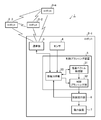
- FIG. 1 is a block diagram illustrating a configuration of a robot group system according to Embodiment 1 of the present invention.
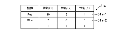
- FIG. 9 is a diagram illustrating an example of a performance vector.
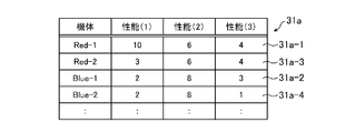
- FIG. 4 is a diagram illustrating a change in a performance vector according to a change in the performance of the airframe.
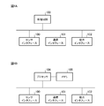
- FIG. 4A is a block diagram showing a hardware configuration for realizing the functions of the control planning device according to Embodiment 1.
- FIG. 4B is a block diagram illustrating a hardware configuration that executes software for realizing the functions of the control planning device according to Embodiment 1.
- 5 is a flowchart illustrating a control planning method according to the first embodiment.
- FIG. 5 is an explanatory diagram illustrating an example of control of a robot group based on a performance vector.
- FIG. 9 is an explanatory diagram showing another example of the control of the robot group based on the performance vector.
- FIG. 11 is an explanatory diagram showing still another example of control of a robot group based on a performance vector.
- FIG. 1 is a block diagram showing a configuration of a robot group system 1 according to Embodiment 1 of the present invention.
- the robot group system 1 forms a group and includes robots 2-1 to 2-4, each of which acts autonomously.
- the control planning device 3 is mounted on each of the robots 2-1 to 2-4.
- the control planning device 3 mounted on the robot 2-1 determines the behavior of the robot 2-1 according to the control rules set for the group.
- the control planning device 3 mounted on the robot 2-2 determines the behavior of the robot 2-2
- the control planning device 3 mounted on the robot 2-3 determines the behavior of the robot 2-3
- the control planning device 3 mounted on -4 determines the action of the robot 2-4.
- a group including the robots 2-1 to 2-4 will be referred to as a robot group
- the robots forming the robot group will be referred to as a machine as appropriate.
- the robots 2-1 to 2-4 also include a sensor 4, a communication unit 5, a control execution unit 6, and a power unit 7 in addition to the control planning device 3.
- FIG. 1 shows a robot group composed of four robots
- the robot group system 1 may be a robot group composed of two or more and less than four robots. It may be a robot group composed of more than two robots.
- the sensor 4 is a device mounted on the robot, and senses a surrounding environment of the mounted robot.
- the sensor 4 includes, for example, a radar, an optical sensor, and an infrared sensor.
- the type of the sensor 4 does not need to be the same for all the robots in the robot group.
- the robot 2-1 has a radar as the sensor 4
- the robots 2-2 and 2-3 have an optical sensor as the sensor 4
- the robot 2-4 has an infrared sensor as the sensor 4. Is also good.
- one robot may include all of a radar, an optical sensor, and an infrared sensor as the sensor 4.
- the communication unit 5 includes a robot including itself (hereinafter, referred to as a first body) and one or more remaining robots (hereinafter, referred to as a second body) constituting a robot group other than the first body. To communicate with The communication unit 5 may communicate with an external device installed in an area within its own communicable range other than the robots constituting the robot group.
- the control execution unit 6 controls the power unit 7 to take the action determined by the control planning device 3.
- the power device 7 is a device that operates the robot, and includes a power source such as a motor or an internal combustion engine, and a power mechanism that converts power generated by the power source into propulsion force of the robot.
- the power mechanism includes wheels, propellers, and the like.
- the first aircraft and the second aircraft can autonomously act by the control execution unit 6 and the power unit 7.
- the control planning device 3 is mounted on each of a plurality of aircraft constituting the robot group, and determines an action to be taken by the mounted aircraft. For example, the control planning device 3 mounted on the first body determines the action to be taken by the first body, and the control planning device 3 mounted on the second body determines the action to be taken by the second body. To determine.
- the control planning device 3 includes an information acquisition unit 30, a performance vector processing unit 31, and a control planning unit 32.
- the information acquisition unit 30 acquires information on performance vectors from a plurality of aircraft constituting a robot group. For example, the information acquisition unit 30 acquires information on the performance vector obtained by the sensor 4 and the control execution unit 6 from the sensor 4 and the control execution unit 6 mounted on the first body. Further, the information acquiring unit 30 acquires from the communication unit 5 the information on the performance vector received from the second device by the communication unit 5. The communication unit 5 transmits the information on the performance vector of the first device obtained by the information obtaining unit 30 to one or more second devices.
- the information acquisition unit 30 provided in the control planning device 3 mounted on the robot 2-1 transmits information on the performance vector of the robot 2-1 to the sensor 4 and the control execution unit 6 mounted on the robot 2-1. To get from.
- the information acquisition unit 30 acquires from the communication unit 5 information on the performance vectors of the robots 2-2 to 2-4 received by the communication unit 5 mounted on the robot 2-1.
- the communication unit 5 transmits the information on the performance vector of the robot 2-1 acquired by the information acquisition unit 30 to the robots 2-2 to 2-4.
- the information on the performance vector is information used for updating the performance vector, and is, for example, sensor information of the sensor 4 and specification information of the power plant 7.
- the performance vector is a vector having a performance value obtained by quantifying the relative performance of the aircraft as an element.
- the performance of the aircraft is the physical specifications of the aircraft and the performance of the devices mounted on the aircraft.
- the physical specifications of the aircraft are the performances of the aircraft specified based on the specification information of the power unit 7 acquired by the information acquisition unit 30, and include, for example, the operable distance, the operable time, and the maximum speed of the aircraft.
- the device performance includes radar performance, optical sensor performance, and infrared sensor performance.
- the performance vector processing unit 31 updates the performance vector set for the aircraft whose performance has changed among the performance vectors set for each aircraft based on the information on the performance vector acquired by the information acquisition unit 30. . For example, based on the information on the performance vector acquired by the information acquisition unit 30, the performance vector processing unit 31 performs the performance setting for the aircraft whose performance has changed among the initial performance vectors set for each aircraft. Update the vector. Note that the initial performance vector may be manually set for each machine before the operation of the robot group. Furthermore, the performance vector processing unit 31 may calculate a performance vector for each aircraft based on the information on the performance vector acquired by the information acquisition unit 30.
- FIG. 2 is a diagram showing an example of the performance vector 31a, and shows a performance vector 31a-1 of the aircraft Red and a performance vector 31a-2 of the aircraft Blue.
- the performance value of the performance (1) in the performance vector 31a-1 of the aircraft Red is “10”, and the performance value of the performance (1) in the performance vector 31a-2 of the aircraft Blue is “2”. It is.
- the performance value of the performance (2) in the performance vector 31a-1 of the body Red is "6", and the performance value of the performance (2) in the performance vector 31a-2 of the body Blue is "8".
- the performance value of performance (3) in the performance vector 31a-1 of the aircraft Red is “4”, and the performance value of performance (3) in the performance vector 31a-2 of the aircraft Blue is “3”.
- the performance value may be a normalized value.
- the operable distance of the robot 2-1 is 5 (km) and the maximum speed is 5 (km / sec)
- the operable distance of the robot 2-2 is 3 (km) and the maximum speed is 20 (km / sec).
- the relative value of the operable distance and the relative value of the maximum speed are normalized so as to be numerical values in the range of 0 to 10. This facilitates comparison of the performance values constituting the performance vector.
- the operable distance 5 (km) of the robot 2-1 is the maximum operable distance of the robot group.
- the maximum value of the range is set to 10.
- 10 (km / sec) which is the maximum speed of the robot 2-2
- 10 (km / sec) is the maximum maximum speed of the robot group.
- 10 (km / sec) which is the maximum speed of the robot 2-1, is 2.5.
- the performance vector processing unit 31 includes a performance vector [10, 2.5] using the performance value of the operable distance of the robot 2-1 and the performance value of the maximum speed as elements, and the performance vector of the operable distance of the robot 2-2.
- the performance vector [6, 10] having the value and the performance value of the maximum speed as elements is output to the control planning unit 32.
- Performance values related to radar performance may be divided into specific performance contents. For example, a performance value indicating the detectable distance of the radar and a performance value indicating the resolution of the radar are divided. The more detailed the contents of the radar performance, the more precisely the behavior of the robot can be controlled. When the contents of the radar performance are the “detectable distance” and the “resolution”, there may be a case where the superiority or the inferiority of the radar performance, in which only one of the performance contents is high, cannot be quantitatively expressed. In this case, which performance content is given priority is set in advance.
- the information acquisition unit 30 periodically acquires information on performance vectors from each of the plurality of aircraft constituting the robot group after the robot group starts a mission (action).
- the performance vector processing unit 31 sets the performance vector that has changed in the performance among the performance vectors set for each aircraft based on the information on the performance vector acquired from each of the plurality of aircraft by the information acquisition unit 30. Update the performance vector.
- FIG. 3 is a diagram showing a change in the performance vector 31a according to a change in the performance of the aircraft.
- each performance value of the performance (1), the performance (2) and the performance (3) in the performance vector 31a-3 of the body Red-2 is the performance vector 31a of the body Red-1. Assume it was the same as -1.
- the performance (1) of the airframe Red-2 deteriorates due to the influence of disturbance, and the performance value of the performance (1) changes from “10” to “ Let us consider the case where it drops to 3 ".
- the performance value of the performance (1) is “2”, the performance value of the performance (2) is “8”, and the performance (3 The performance value of ()) is “3”.
- the performance value of the performance (1) is “3”, and the performance value of the performance (2) is “6”.
- the performance value of (3) is “4”.
- the performance of the fuselage Red-2 is close to that of the fuselage Blue-1 having the highest performance value of the performance (2) due to the deterioration of the performance (1). That is, although the body Red-2 can no longer fulfill the same role as the body Red-1, it can be treated as a body capable of playing a role similar to the body Blue-1.
- the performance values of the performance (1), the performance (2) and the performance (3) in the performance vector 31a-4 of the body Blue-2 are the performance values of the body Blue-1. Assume that it was the same as the vector 31a-2. Thereafter, during the mission of the robot group, the performance (3) of the body Blue-2 deteriorates due to the influence of the disturbance, and the performance value of the performance (3) changes from “3” to “ Let us consider the case where it has dropped to 1 ".
- the fuselage Blue-2 has the highest performance value of the performance (2) even when the performance (3) is deteriorated, and maintains a performance close to that of the fuselage Blue-1. That is, the aircraft Blue-2 can be treated as an aircraft that plays a role similar to the aircraft Blue-1, even after the performance (3) is degraded.
- a performance vector for each aircraft based on performance values obtained by quantifying the relative performance of the aircraft, even if the performance of the aircraft is degraded, a plurality of aircraft constituting the robot group may be used. Can be classified based on the performance vector.
- the control planning unit 32 determines the behavior of the first machine on which the control planning device 3 including itself is mounted, among the control planning devices 3 mounted on each of the plurality of machines constituting the robot group. In determining an action by the control planning unit 32, a control rule based on the performance vector of the first aircraft and the performance vector of the second aircraft is used. When either the performance vector of the first aircraft or the performance vector of the second aircraft is updated by the performance vector processing unit 31, the control planning unit 32 executes the first control rule according to the control rule based on the updated performance vector. Determine the behavior of the aircraft.
- the control rules include, for example, a control rule (A) based on the cosine similarity between the performance vectors of the bodies forming the robot group, and the performance vectors of the bodies forming the robot group and the environment in which this body exists.
- the environment in which the aircraft exists is a point in the area where the aircraft exists or in the vicinity of the aircraft.
- the control rule (A) based on the cosine similarity between the performance vectors between the bodies constituting the robot group will be described later in detail with reference to FIG.
- the control rule (B) based on the cosine similarity between the performance vector of the body constituting the robot group and the performance vector requested from the environment where the body exists is described in detail with reference to FIGS. It will be described later.
- control planning device 3 includes a processing circuit for executing processing of each step in a flowchart shown in FIG. 5 described below.
- the processing circuit may be dedicated hardware, or may be a CPU (Central Processing Unit) that executes a program stored in the memory.
- FIG. 4A is a block diagram showing a hardware configuration for realizing the functions of the control planning device 3.
- FIG. 4B is a block diagram illustrating a hardware configuration that executes software for realizing the functions of the control planning device 3.
- a sensor interface 100 is an interface for relaying sensor information detected by the sensor 4 shown in FIG.
- the information acquisition unit 30 acquires sensor information from the sensor 4 via the sensor interface 100.
- the communication interface 101 is an interface that relays information transmitted and received by the communication unit 5 illustrated in FIG.
- the information acquisition unit 30 acquires information on the performance vector from the communication unit 5 via the communication interface 101.
- the power interface 102 is an interface for relaying a control signal to the control execution unit 6 shown in FIG.
- the control planning unit 32 outputs a control signal indicating an action to be taken by the first body to the control execution unit 6 via the power interface 102.
- the control execution 6 operates the first body by controlling the power unit 7 shown in FIG. 1 according to the control signal.
- the processing circuit 103 may be, for example, a single circuit, a composite circuit, a programmed processor, a parallel programmed processor, or an ASIC (Application Specialized Integrated). Circuit, FPGA (Field-Programmable Gate Array), or a combination thereof.
- the functions of the information acquisition unit 30, the performance vector processing unit 31, and the control planning unit 32 in the control planning device 3 may be realized by separate processing circuits, or these functions may be realized together by one processing circuit. Good.
- the processing circuit is the processor 104 shown in FIG. 4B
- the functions of the information acquisition unit 30, the performance vector processing unit 31, and the control planning unit 32 in the control planning device 3 are software, firmware, or a combination of software and firmware. It is realized by.
- the software or firmware is described as a program and stored in the memory 108.
- the processor 104 reads out and executes the program stored in the memory 105 to realize the functions of the information acquisition unit 30, the performance vector processing unit 31, and the control planning unit 32 in the control planning device 3. That is, the control planning device 3 includes a memory 105 for storing a program that, when executed by the processor 104, results in the processing of steps ST1 to ST3 in the flowchart of FIG. These programs cause a computer to execute the procedure or method of the information acquisition unit 30, the performance vector processing unit 31, and the control planning unit 32 in the control planning device 3.
- the memory 105 may be a computer-readable storage medium storing a program for causing a computer to function as the information acquisition unit 30, the performance vector processing unit 31, and the control planning unit 32 in the control planning device 3.
- the memory 105 is, for example, a nonvolatile memory such as a RAM (Random Access Memory), a ROM (Read Only Memory), a flash memory, an EPROM (Erasable Programmable Read Only Memory), an EEPROM (Electrically-EPROM), or a nonvolatile semiconductor memory.
- Discs, flexible discs, optical discs, compact discs, mini discs, DVDs, and the like are applicable.
- the functions of the information acquisition unit 30, the performance vector processing unit 31, and the control planning unit 32 in the control planning device 3 may be partially realized by dedicated hardware, and partially realized by software or firmware.
- the information acquisition unit 30 implements the functions of the processing circuit 103 that is dedicated hardware, and the performance vector processing unit 31 and the control planning unit 32 allow the processor 104 to read and execute a program stored in the memory 105.
- the function is realized by.
- the processing circuit can realize the above functions by hardware, software, firmware, or a combination thereof.
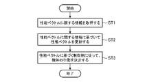
- FIG. 5 is a flowchart illustrating a control planning method according to the first embodiment.
- the information obtaining unit 30 obtains information on a performance vector from a plurality of aircraft constituting a robot group (step ST1).
- the information acquisition unit 30 acquires information related to the performance vector of the first aircraft from the first aircraft equipped with the control planning device 3 provided therein, and configures a robot group other than the first aircraft.
- Information about the performance vector of the second aircraft is obtained from the remaining one or more second aircraft.
- the information on the performance vector is, for example, the sensor information of the sensor 4 and the specification information of the power unit 7, but may be the initial performance vector described above.
- the performance vector processing unit 31 updates, based on the information acquired by the information acquisition unit 30, the performance vector set for the aircraft whose performance has changed among the performance vectors set for each aircraft (step ST2). ).
- the performance vector processing unit 31 calculates the performance vector of the second aircraft based on the sensor information of the sensors 4 of the first aircraft and the second aircraft acquired by the information acquiring unit 30 and the specification information of the power unit 7. To update.
- the control planning unit 32 determines the behavior of the aircraft according to a control rule based on the performance vector (step ST3).
- the control planning unit 32 determines the behavior of the first body equipped with the control planning apparatus 3 including itself among the control planning apparatuses 3 mounted on each of the plurality of bodies constituting the robot group. For example, a control rule based on the cosine similarity between the performance vector of the first device and the performance vector of the second device is used to determine the behavior of the first device.
- the control execution unit 6 controls the power unit 7 to take the action determined by the control planning unit 32.
- the power unit 7 controls the operation of the first body according to the control from the control execution unit 6. Thereby, the first body and the second body behave autonomously.
- the cosine similarity of performance vectors between the aircraft is large with respect to the control planning unit 32 of each of the plurality of aircraft constituting the robot group. As the cosine similarity is smaller, the control rule is set to move the airplane closer to the airplane.
- the cosine similarity is an index indicating how similar two vectors are. Two performance vectors having a large cosine similarity are similar, and two performance vectors having a small cosine similarity are not similar.
- control rules are set in advance for each of the plurality of aircraft constituting the robot group before the robot group starts a mission.
- the performance vector can be updated even after the robot group starts the mission.
- the cosine similarity of the performance vectors of the aircrafts is small with respect to the control planning unit 32 of each of the plurality of aircrafts constituting the robot group.
- a control rule is set to move the aircraft further away from the aircraft.
- the respective bodies constituting the robot group act according to this control rule, whereby a body having similar performance is approached, and a body having similar performance is moved away.
- the control of the robot group can be continued without significantly changing the positions of the plurality of aircraft constituting the robot group.
- the control planning unit 32 included in the first aircraft is configured to execute the performance vector of the first aircraft and all the control vectors existing within the communicable range of the communication unit 5.
- the cosine similarity with the performance vector of the second aircraft is calculated.
- the control planning unit 32 included in the first body determines that the second body having the performance vector whose cosine similarity is equal to or larger than the threshold value in the forward direction from the first body to the second body and has a cosine similarity.
- a movement vector having the same length as the degree is calculated.
- the control planning unit 32 included in the first aircraft is in the reverse direction from the second aircraft to the first aircraft, and A motion vector having a length obtained by subtracting the cosine similarity is calculated.
- the control planning unit 32 included in the first body calculates the above-described movement vectors for all the second bodies existing within the communicable range of the communication unit 5, and calculates the sum of all the calculated movement vectors as the final movement. Vector.
- the control planning unit 32 included in the first body repeats these processes at every change cycle of the formation of the robot group.
- the performance vector processing unit 31 included in the first machine updates the performance vector of the first machine before calculating the cosine similarity.
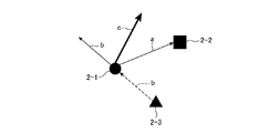
- FIG. 6 is an explanatory diagram showing an example of control of the robot group based on the performance vector, and shows a specific example of a control rule (A) based on the cosine similarity of the performance vectors between the bodies forming the robot group.
- the control planning unit 32 provided in the robot 2-1 includes, as a control rule (A), the more the cosine similarity of the performance vectors of the airframes, the more the aircraft is farther away, and the higher the cosine similarity, the more the airframe.
- a control rule to approach is set.
- the control planning unit 32 included in the robot 2-1 determines the performance vector of the robot 2-1 and the performance of each of the robots 2-2 and 2-3 existing within the communicable range of the communication unit 5 included in the robot 2-1. Calculate the cosine similarity with the vector.
- the threshold value of the cosine similarity is set to 0.5.
- the cosine similarity between the performance vectors of the robot 2-1 and the robot 2-2 is 0.7
- the cosine similarity between the performance vectors of the robot 2-1 and the robot 2-3 is 0.4. I do.
- the cosine similarity between the performance vector of the robot 2-1 and the performance vector of the robot 2-2 is 0.7 and is equal to or larger than the threshold value 0.5.
- the control planning unit 32 provided in the robot 2-1 sets the movement vector a having the same value (0.7) as the cosine similarity in the direction from the robot 2-1 to the robot 2-2. I do.
- the cosine similarity between the performance vector of the robot 2-1 and the performance vector of the robot 2-3 is 0.4 and less than the threshold value 0.5.
- the control planning unit 32 provided in the robot 2-1 moves the movement vector having a length (0.6) obtained by subtracting the cosine similarity from 1 in the direction from the robot 2-2 to the robot 2-1.
- Set b. The control planning unit 32 provided in the robot 2-1 calculates a movement vector c of the sum of the movement vector a and the movement vector b. Then, the control planning unit 32 provided in the robot 2-1 calculates the moving direction and the moving distance of the robot 2-1 based on the moving vector c.
- the information acquisition unit 30 uses the communication unit 5 to acquire a performance vector required from the environment side (area) to be monitored.
- the external device installed for each area may transmit the performance vector required from the area.
- the information acquisition unit 30 may collectively acquire the performance vectors required from each of the plurality of areas from the external device managing the performance vectors regarding the plurality of areas using the communication unit 5. .
- the control planning unit 32 included in the first aircraft calculates a cosine similarity between the performance vector of the first aircraft and the performance vector acquired from the area by the information acquisition unit 30.
- a control rule of allocating an airframe having a performance vector having a large cosine similarity to a performance vector requested from an area to monitor this area is determined by a plurality of airframes constituting a robot group. Are set in the control planning unit 32 of each of the.
- the aircraft having the sensors 4 having similar performances monitor the same area.
- An aircraft with high radar performance is assigned to an area to be monitored by radar, and an aircraft with high optical sensor performance is assigned to an area to be monitored by an optical sensor.
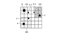
- FIG. 7 is an explanatory diagram illustrating an example of control of a robot group based on a performance vector, in which a cosine similarity between a performance vector of a body constituting the robot group and a performance vector requested from an environment where the body exists.
- 9 shows a specific example of a control rule (B) based on degrees.
- areas 200 to 202 are environments where the aircraft exists.
- An external device for managing a performance vector A required by the area 200 is installed in the area 200
- an external device for managing a performance vector B required by the area 201 is installed in the area 201
- an area 202 is installed in the area 202.
- An external device that manages the performance vector C required by 202 is installed.
- the information acquisition unit 30 provided in the robot 2-1 acquires the performance vector A requested from the area 200 from the external device using the communication unit 5.
- the information acquisition unit 30 provided in the robot 2-2 acquires the performance vector B requested from the area 201 using the communication unit 5.
- the information acquisition unit 30 provided in the robot 2-3 acquires the performance vector C requested from the area 202 using the communication unit 5.
- the control planning unit 32 included in each of the robots 2-1, 2-2, and 2-3 includes, as a control rule (B), a performance vector having a large cosine similarity with a performance vector requested from a certain area. Is assigned to monitoring of this area.
- the control planning unit 32 included in the robot 2-1 calculates a cosine similarity between the performance vector of the robot 2-1 and the performance vector A acquired by the information acquisition unit 30.
- the control planning unit 32 included in the robot 2-2 calculates the cosine similarity between the performance vector of the robot 2-2 and the performance vector B acquired by the information acquiring unit 30, and controls the robot 2-3.
- the planning unit 32 calculates a cosine similarity between the performance vector of the robot 2-3 and the performance vector C acquired by the information acquisition unit 30.
- the control planning unit 32 provided in the robot 2-1 determines the action of the robot 2-1 in the area 200. Decide to move to.
- the control execution unit 6 of the robot 2-1 controls the operation of the robot 2-1 so as to take the action determined by the control planning unit 32. Thereby, the robot 2-1 is assigned to the monitoring of the area 200.
- the cosine similarity between the performance vector of the robot 2-2 and the performance vector B requested from the area 201 is smaller than the threshold value, and the cosine of the performance vector of the robot 2-3 and the performance vector C requested from the area 202 is smaller. If the similarity is less than the threshold, the robot 2-2 is not assigned to monitoring the area 201, and the robot 2-3 is not assigned to monitoring the area 202. In this case, the control planning unit 32 provided in the robot 2-2 determines the action of the robot 2-2 moving away from the area 201, and the control planning unit 32 provided in the robot 2-3 also moves the robot 2-3 away from the area 202. Determine action.
- the control execution unit 6 included in the robot 2-2 controls the operation of the robot 2-2 so as to take the action determined by the control planning unit 32.
- the control execution unit 6 included in the robot 2-3 includes a control planning unit. The operation of the robot 2-3 is controlled so as to take the action determined by 32.
- a control rule for moving to the center of gravity of the Voronoi region to which the first body belongs is set as a control rule (B) for each of the plurality of bodies constituting the robot group.
- the information acquisition unit 30 included in the first machine acquires performance vectors from all the second machines existing within the communicable range of the communication unit 5.
- the control planning unit 32 included in the first aircraft calculates a cosine similarity between the performance vector of the first aircraft and the performance vector of the second aircraft acquired by the information acquiring unit 30.
- the control planning unit 32 provided in the first device determines that the second device whose cosine similarity is equal to or greater than the threshold value 0.5 is the second device from the first device. A movement vector toward the aircraft and having the same length as the value of the cosine similarity is set.
- the control planning unit 32 included in the first aircraft for the second aircraft whose cosine similarity is less than the threshold value 0.5, calculates the value of the cosine similarity from the second aircraft to the first aircraft. A movement vector having the same length is set.
- the control planning unit 32 included in the first body sets the movement vectors for all the second bodies existing within the communicable range of the communication unit 5, and sets the vector of the sum of the movement vectors and the first body. Of the Voronoi region to which the first body belongs from the position of.
- the control planning unit 32 included in the first body determines the moving direction and the moving distance of the first body based on the calculated sum vector.
- the control planning unit 32 included in the first machine repeatedly executes this process for each control update cycle.
- the performance vector processing unit 31 included in the first body updates the performance vector of the first body before the cosine similarity is calculated.
- the information acquisition unit 30 acquires a performance vector requested from the environment side (point) to be visited.
- the external device installed for each point may transmit the performance vector required from the point.
- the information acquisition unit 30 may collectively acquire the performance vectors required from each of the plurality of points from the external device that manages the performance vectors regarding the plurality of points, using the communication unit 5.
- the control planning unit 32 included in the first aircraft calculates a cosine similarity between the performance vector of the first aircraft and the performance vector acquired from the point by the information acquisition unit 30.
- the control planning unit 32 included in each of the plurality of aircraft constituting the robot group includes, as a control rule (B), an aircraft having a performance vector having a large cosine similarity with a performance vector requested from a point, A control rule for traveling around this point is set.
- the aircraft having the sensors 4 having similar performances tour the same point.
- the patrol frequency of the aircraft with high radar performance is increased.
- the frequency of patrol of the aircraft with high optical sensor performance is increased. Is done.
- FIG. 8 is an explanatory diagram showing an example of control of a robot group based on a performance vector, in which a cosine similarity between a performance vector of a body constituting the robot group and a performance vector requested from an environment where the body exists is shown.
- 9 shows a specific example of a control rule (B) based on degrees.
- an external device for managing a performance vector A is installed at a point P1
- an external device for managing a performance vector B is installed at a point P2
- an external device for managing a performance vector C is installed at a point P3.
- Equipment is installed.
- the information acquisition unit 30 provided in the robot 2-1 acquires the performance vector A requested from the point P1 from the external device using the communication unit 5.
- the information acquisition unit 30 included in the robot 2-2 acquires the performance vector B requested from the point P2 using the communication unit 5.
- the information acquisition unit 30 provided in the robot 2-3 uses the communication unit 5 to acquire the performance vector C requested from the point P3.
- the control planning unit 32 provided in each of the robots 2-1, 2-2, and 2-3 includes, as a control rule (B), a performance vector having a large cosine similarity with a performance vector requested from a certain point.
- a control rule is set so that the aircraft having the circumstance is made to circulate to this point.
- the control planning unit 32 included in the robot 2-1 calculates the cosine similarity between the performance vector of the robot 2-1 and the performance vector A acquired by the information acquisition unit 30.
- the control planning unit 32 included in the robot 2-2 calculates the cosine similarity between the performance vector of the robot 2-2 and the performance vector B acquired by the information acquiring unit 30, and controls the robot 2-3.
- the planning unit 32 calculates a cosine similarity between the performance vector of the robot 2-3 and the performance vector C acquired by the information acquisition unit 30.
- the control planning unit 32 provided in the robot 2-1 determines the action of the robot 2-1 as the point P1. Decide to move to.
- the control execution unit 6 included in the robot 2-1 controls the operation of the robot 2-1 so as to take the action determined by the control planning unit 32. Thereby, the robot 2-1 goes around the point P1.
- the cosine similarity between the performance vector of the robot 2-2 and the performance vector B requested from the point P2 is less than the threshold value, and the cosine of the performance vector of the robot 2-3 and the performance vector C requested from the point P3.
- the point P2 is not set as the tour point of the robot 2-2, and the point P3 is not set as the tour point of the robot 2-3.
- control planning unit 32 of the robot 2-2 determines a route that does not go around the point P2
- control planning unit 32 of the robot 2-3 also determines a route that does not go around the point P3.
- the control execution unit 6 included in the robot 2-2 controls the operation of the robot 2-2 so as to take the action determined by the control planning unit 32
- the control execution unit 6 included in the robot 2-3 performs control planning.
- the operation of the robot 2-3 is controlled so that the action determined by the unit 32 is taken.
- each of the plurality of bodies constituting the robot group has, as a control rule (B), a period that has elapsed since the last time the sensing was executed among the points existing within the sensing range of the sensor 4 provided in the body. Is set next to the longest point.
- the information acquisition unit 30 included in the first machine acquires the performance vector from the external devices installed at all points existing within the sensing range of the sensor 4 using the communication unit 5.
- the control planning unit 32 included in the first body calculates the cosine similarity between the performance vector of the first body and a performance vector requested from the points for all points existing within the sensing range. Subsequently, the control planning unit 32 included in the first body determines a point having the longest elapsed time since the previous sensing is executed as a point to be visited next among the plurality of calculated cosine similarities. .
- the control planning unit 32 included in the first machine repeats the above-described series of processing every time the tour point is determined.
- the performance vector processing unit 31 included in the first body updates the performance vector of the first body before the cosine similarity is calculated.
- the control planning device 3 updates the performance vector having the performance value obtained by quantifying the relative performance of the body as an element, and performs the behavior of the body according to the control rule based on the performance vector. To determine. Even if one of the multiple aircraft constituting the robot group breaks down and its performance changes, the performance vector of that aircraft is updated to reflect the change in performance. , The resistance to the failure of the airframe can be increased.
- control planning unit 32 determines the behavior of the aircraft according to a control rule based on the cosine similarity of the performance vectors between the aircraft constituting the robot group. Thereby, the behavior of the robot group can be controlled based on the performance between the airframes.
- control planning unit 32 controls the behavior of the aircraft according to a control rule based on the cosine similarity between the performance vector of the aircraft constituting the robot group and the performance vector requested by the environment. To determine. This makes it possible to control the behavior of the robot group based on the performance of the body constituting the robot group and the performance requested from the environment.
- the robot group system according to Embodiment 1 has the configuration shown in FIG. 1, so that even if one of a plurality of bodies constituting the robot group fails and the performance changes, the robot group system Update the performance vector to reflect the change in performance. This makes it possible to increase the resistance of the plurality of bodies constituting the robot group to failure of the body in the control of the plurality of bodies.
- the control planning method according to the first embodiment by performing the series of processes illustrated in FIG. 5, it is possible to increase resistance to a failure of a body in controlling a plurality of bodies forming a robot group.
- the control planning device can increase the resistance to a failure of a machine in controlling a plurality of machines constituting a group, and thus can be used for, for example, various robot systems.
- 1 robot group system 2-1, 2-2, 2-3, 2-4 robot, 3 control planning device, 4 sensor, 5 communication unit, 6 control execution unit, 7 power unit, 30 information acquisition unit, 31 performance Vector processing unit, 31a, 31a-1, 31a-2, 31a-3, 31a-4 performance vector, 32 control planning unit, 100 sensor interface, 101 communication interface, 102 power interface, 103 processing circuit, 104 processor, 105 memory , 200, 201, 202 area.
Landscapes
- Engineering & Computer Science (AREA)
- Aviation & Aerospace Engineering (AREA)
- Radar, Positioning & Navigation (AREA)
- Remote Sensing (AREA)
- Physics & Mathematics (AREA)
- General Physics & Mathematics (AREA)
- Automation & Control Theory (AREA)
- Control Of Position, Course, Altitude, Or Attitude Of Moving Bodies (AREA)
Abstract
制御プランニング装置(3)は、機体の相対的な性能が数値化された性能値を要素とする性能ベクトルを更新し、性能ベクトルに基づく制御則に従って機体の行動を決定する。
Description
本発明は、集団を構成し、各々が自律的に行動する複数の機体のそれぞれの行動を決定する制御プランニング装置、ロボット群システムおよび制御プランニング方法に関する。
ロボット群を制御する方法の一つとしてリーダ追従型の制御方法がある。この制御方法は、ロボットに搭載されている機器の種類および性能がロボットごとに異なるヘテロな系を有したロボット群に採用されることが多い。
例えば、特許文献1には、リーダ追従型の制御方法を採用したロボット群の制御方法が記載されている。特許文献1に記載された制御方法では、計算能力を有した親ロボット(リーダ機)がロボット群の全ての子ロボットの行動を俯瞰し、個々の子ロボットの最適な行動を決定することで効率的なロボット群の制御を実現している。
親ロボットには、周囲環境に存在する検知対象物に接触せずに検知する非接触型センサが搭載されており、子ロボットには、周囲環境に存在する検知対象物に接触して検知する接触型センサが搭載されている。このロボット群システムでは、親ロボットが子ロボットの行動を決定するので、子ロボットが障害物に接触して壊れてしまっても、親ロボットが壊れない限り、ロボット群としては活動を継続できる。
特許文献1に記載された制御方法では、親ロボットに非接触型センサが搭載されていても、何らかの影響で親ロボット自体が故障してしまうと、ロボット群としての活動が継続できないという課題があった。
本発明は上記課題を解決するものであり、集団を構成する複数の機体の制御における機体の故障に対する耐性を高めることができる制御プランニング装置、ロボット群制御システムおよび制御プランニング方法を得ることを目的とする。
本発明に係る制御プランニング装置は、集団を構成し、各々が自律的に行動する複数の機体のそれぞれに搭載され、搭載された機体がとるべき行動を決定する。制御プランニング装置は、情報取得部、性能ベクトル処理部および制御プランニング部を備えている。情報取得部は、機体の相対的な性能が数値化された性能値を要素とする性能ベクトルに関する情報を、複数の機体から取得する。性能ベクトル処理部は、情報取得部によって取得された性能ベクトルに関する情報に基づいて、機体ごとに設定された性能ベクトルのうち、性能に変化があった機体に設定された性能ベクトルを更新する。制御プランニング部は、性能ベクトルに基づく制御則に従って機体の行動を決定する。
本発明によれば、機体の相対的な性能が数値化された性能値を要素とする性能ベクトルを更新し、性能ベクトルに基づく制御則に従って機体の行動を決定する。集団を構成する複数の機体のいずれかが故障して性能が変化した場合であってもその機体の性能ベクトルを更新して性能の変化を反映させるので、集団を構成する複数の機体の制御における機体の故障に対する耐性を高めることができる。
以下、本発明をより詳細に説明するため、本発明を実施するための形態について、添付の図面に従って説明する。
実施の形態1.
図1は、本発明の実施の形態1に係るロボット群システム1の構成を示すブロック図である。ロボット群システム1は、図1に示すように、集団を構成し、各々が自律的に行動するロボット2-1~2-4を備える。制御プランニング装置3は、ロボット2-1~2-4のそれぞれに搭載されている。ロボット2-1に搭載された制御プランニング装置3は、上記集団に設定された制御則に従って、ロボット2-1の行動を決定する。ロボット2-2に搭載された制御プランニング装置3は、ロボット2-2の行動を決定し、ロボット2-3に搭載された制御プランニング装置3は、ロボット2-3の行動を決定し、ロボット2-4に搭載された制御プランニング装置3は、ロボット2-4の行動を決定する。以降では、ロボット2-1~2-4から構成される集団をロボット群と記載し、ロボット群を構成するロボットを、適宜、機体と記載する。
実施の形態1.
図1は、本発明の実施の形態1に係るロボット群システム1の構成を示すブロック図である。ロボット群システム1は、図1に示すように、集団を構成し、各々が自律的に行動するロボット2-1~2-4を備える。制御プランニング装置3は、ロボット2-1~2-4のそれぞれに搭載されている。ロボット2-1に搭載された制御プランニング装置3は、上記集団に設定された制御則に従って、ロボット2-1の行動を決定する。ロボット2-2に搭載された制御プランニング装置3は、ロボット2-2の行動を決定し、ロボット2-3に搭載された制御プランニング装置3は、ロボット2-3の行動を決定し、ロボット2-4に搭載された制御プランニング装置3は、ロボット2-4の行動を決定する。以降では、ロボット2-1~2-4から構成される集団をロボット群と記載し、ロボット群を構成するロボットを、適宜、機体と記載する。
また、ロボット2-1~2-4は、制御プランニング装置3の他に、センサ4、通信部5、制御実行部6および動力装置7を備えている。なお、図1には、4台のロボットから構成されたロボット群を示したが、ロボット群システム1は、2台以上4台未満のロボットから構成されたロボット群であってもよいし、5台以上のロボットから構成されたロボット群であってもよい。
センサ4は、ロボットに搭載された機器であり、搭載されたロボットの周辺環境をセンシングする。センサ4には、例えば、レーダ、光学センサおよび赤外線センサがある。センサ4の種類は、ロボット群の全てのロボットで同一である必要はない。例えば、ロボット2-1は、センサ4としてレーダを搭載し、ロボット2-2,2-3は、センサ4として光学センサを搭載し、ロボット2-4では、センサ4として赤外線センサを搭載してもよい。また、一つのロボットが、センサ4としてレーダ、光学センサおよび赤外線センサの全てを備えてもよい。
通信部5は、自身を備えるロボット(以下、第1の機体と記載する)と第1の機体以外にロボット群を構成する残りの1または複数のロボット(以下、第2の機体と記載する)との間で通信を行う。通信部5は、ロボット群を構成するロボット以外に、自身の通信可能範囲内のエリアに設置された外部装置との間で通信を行ってもよい。
制御実行部6は、制御プランニング装置3によって決定された行動をとるように、動力装置7を制御する。動力装置7は、ロボットを動作させる装置であり、モータまたは内燃機関といった動力源と、動力源によって発生された動力を、ロボットの推進力に変換する動力機構とが含まれる。動力機構には、車輪、プロペラなどがある。第1の機体と第2の機体は、制御実行部6および動力装置7によって自律的に行動することが可能である。
制御プランニング装置3は、ロボット群を構成する複数の機体のそれぞれに搭載され、搭載された機体がとるべき行動を決定する。例えば、第1の機体に搭載された制御プランニング装置3は、第1の機体がとるべき行動を決定し、第2の機体に搭載された制御プランニング装置3は、第2の機体がとるべき行動を決定する。制御プランニング装置3は、情報取得部30、性能ベクトル処理部31および制御プランニング部32を備える。
情報取得部30は、ロボット群を構成する複数の機体から、性能ベクトルに関する情報を取得する。例えば、情報取得部30は、センサ4および制御実行部6によって得られた性能ベクトルに関する情報を、第1の機体に搭載されたセンサ4および制御実行部6から取得する。さらに、情報取得部30は、通信部5によって第2の機体から受信された性能ベクトルに関する情報を、通信部5から取得する。通信部5は、情報取得部30によって取得された第1の機体の性能ベクトルに関する情報を、1または複数の第2の機体へ送信する。
図1において、ロボット2-1に搭載された制御プランニング装置3が備える情報取得部30は、ロボット2-1の性能ベクトルに関する情報を、ロボット2-1に搭載されたセンサ4および制御実行部6から取得する。情報取得部30は、ロボット2-1に搭載された通信部5によって受信されたロボット2-2~2-4のそれぞれの性能ベクトルに関する情報を、当該通信部5から取得する。通信部5は、情報取得部30によって取得されたロボット2-1の性能ベクトルに関する情報を、ロボット2-2~2-4に送信する。
性能ベクトルに関する情報は、性能ベクトルの更新に使用される情報であり、例えば、センサ4のセンサ情報および動力装置7のスペック情報である。性能ベクトルとは、機体の相対的な性能が数値化された性能値を要素とするベクトルである。機体の性能は、機体の物理的なスペックおよび機体に搭載された機器の性能である。機体の物理的なスペックは、情報取得部30によって取得された動力装置7のスペック情報に基づいて特定される機体の性能であり、例えば、機体の稼働可能距離、稼働可能時間および最高速度がある。機体に搭載された機器がセンサ4である場合、機器の性能には、レーダ性能、光学センサ性能および赤外線センサ性能がある。
性能ベクトル処理部31は、情報取得部30によって取得された性能ベクトルに関する情報に基づいて、機体ごとに設定された性能ベクトルのうち、性能に変化のあった機体に設定された性能ベクトルを更新する。例えば、性能ベクトル処理部31は、情報取得部30によって取得された性能ベクトルに関する情報に基づいて、機体ごとに設定された初期の性能ベクトルのうち、性能に変化があった機体に設定された性能ベクトルを更新する。なお、初期の性能ベクトルは、ロボット群の稼働前に、人手で機体ごとに設定してもよい。さらに、性能ベクトル処理部31は、情報取得部30によって取得された性能ベクトルに関する情報に基づいて、機体ごとの性能ベクトルを算出してもよい。
図2は、性能ベクトル31aの例を示す図であり、機体Redの性能ベクトル31a-1と、機体Blueの性能ベクトル31a-2とを示している。図2に示すように、機体Redの性能ベクトル31a-1における性能(1)の性能値は“10”であり、機体Blueの性能ベクトル31a-2における性能(1)の性能値は“2”である。機体Redの性能ベクトル31a-1における性能(2)の性能値は“6”であり、機体Blueの性能ベクトル31a-2における性能(2)の性能値は“8”である。機体Redの性能ベクトル31a-1における性能(3)の性能値は“4”であり、機体Blueの性能ベクトル31a-2における性能(3)の性能値は“3”である。
性能値は、正規化された値であってもよい。例えば、ロボット2-1の稼働可能距離が5(km)、最高速度が5(km/sec)であり、ロボット2-2の稼働可能距離が3(km)、最高速度が20(km/sec)である場合に、稼働可能距離の相対値および最高速度の相対値とを0から10までの範囲内の数値となるように正規化する。これにより、性能ベクトルを構成する性能値の比較が容易になる。
例えば、ロボット群がロボット2-1およびロボット2-2から構成されている場合、ロボット2-1の稼働可能距離である5(km)は、ロボット群で最大の稼働可能距離であるので、上記範囲の最大値である10とする。最大値の10に対して、ロボット2-2の稼働可能距離である3(km)は6となる。ロボット2-2の最高速度である20(km/sec)は、ロボット群で最大の最高速度であるので、上記範囲の最大値である10とする。最大値の10に対して、ロボット2-1の最高速度である5(km/sec)は2.5となる。
性能ベクトル処理部31は、ロボット2-1の稼働可能距離の性能値と最高速度の性能値とを要素とした性能ベクトル[10,2.5]と、ロボット2-2の稼働可能距離の性能値と最高速度の性能値とを要素とした性能ベクトル[6,10]とを、制御プランニング部32に出力する。
レーダ性能に関する性能値は、具体的な性能の内容に分けてもよい。例えば、レーダの探知可能距離を示す性能値と、レーダの分解能を示す性能値に分ける。レーダ性能の内容が詳細であるほど、ロボットの行動を緻密に制御することが可能となる。
なお、レーダ性能の内容が“探知可能距離”および“分解能”である場合に、どちらか一方の性能の内容のみが高いというレーダ性能の優劣を定量的に表現することができない場合が考えられる。この場合、どちらの性能の内容を優先するかを予め設定しておく。
なお、レーダ性能の内容が“探知可能距離”および“分解能”である場合に、どちらか一方の性能の内容のみが高いというレーダ性能の優劣を定量的に表現することができない場合が考えられる。この場合、どちらの性能の内容を優先するかを予め設定しておく。
情報取得部30は、ロボット群がミッション(行動)を開始してから、性能ベクトルに関する情報を、ロボット群を構成する複数の機体のそれぞれから周期的に取得する。性能ベクトル処理部31は、情報取得部30によって複数の機体のそれぞれから取得された性能ベクトルに関する情報に基づいて、機体ごとに設定された性能ベクトルのうち、性能に変化のあった機体に設定された性能ベクトルを更新する。
従来のロボット群の制御では、ロボット群を構成する複数の機体のうち、いずれかの性能が劣化した場合、性能が劣化した機体はないものとして扱われるか、あるいは機体の性能劣化に伴ったロボット群全体の制御効率の低下を補う処理が実行されるだけであった。これに対して、実施の形態1に係る制御プランニング装置3では、性能が劣化した機体をロボット群の制御対象から除くのではなく、性能が異なる新たな機体として扱うことで、機体の性能の変化に応じたロボット群の制御が可能である。
図3は、機体の性能の変化に応じた性能ベクトル31aの変化を示す図である。ロボット群がミッションを開始した当初、機体Red-2の性能ベクトル31a-3における、性能(1)、性能(2)および性能(3)の各々の性能値は、機体Red-1の性能ベクトル31a-1と同じであったと仮定する。この後、ロボット群のミッションの途中に、外乱の影響で機体Red-2の性能(1)が劣化して、性能(1)の性能値が“10”から、図3に示すように、“3”に低下した場合を考える。
図3に示すように、機体Blue-1の性能ベクトル31a-2における、性能(1)の性能値は“2”であり、性能(2)の性能値は“8”であり、性能(3)の性能値は“3”である。一方、性能(1)が劣化した機体Red-2の性能ベクトル31a-3における、性能(1)の性能値は“3”であり、性能(2)の性能値は“6”であり、性能(3)の性能値は“4”である。このように、機体Red-2は、性能(1)が劣化したことにより、性能(2)の性能値が最も高い機体Blue-1に近い性能になっている。すなわち、機体Red-2は、機体Red-1と同じ役割は果たせなくなったが、機体Blue-1に類似した役割を果たせる機体として扱うことができる。
また、ロボット群がミッションを開始した当初、機体Blue-2の性能ベクトル31a-4における、性能(1)、性能(2)および性能(3)の各々の性能値は、機体Blue-1の性能ベクトル31a-2と同じであったと仮定する。この後、ロボット群のミッションの途中に、外乱の影響で機体Blue-2の性能(3)が劣化して、性能(3)の性能値が“3”から、図3に示すように、“1”に低下した場合を考える。
機体Blue-2は、性能(3)が劣化しても、性能(2)の性能値が最も高く、機体Blue-1に近い性能を維持している。すなわち、機体Blue-2は、性能(3)が劣化した後であっても、機体Blue-1と類似した役割を果たせる機体として扱うことができる。このように機体の相対的な性能を数値化した性能値を要素とする性能ベクトルを機体ごとに作成することによって、機体の性能が劣化した場合であっても、ロボット群を構成する複数の機体を、性能ベクトルを基準として分類することができる。
制御プランニング部32は、ロボット群を構成する複数の機体のそれぞれに搭載された制御プランニング装置3のうち、自身を備える制御プランニング装置3が搭載された第1の機体の行動を決定する。制御プランニング部32による行動の決定には、第1の機体の性能ベクトルおよび第2の機体の性能ベクトルに基づく制御則が用いられる。性能ベクトル処理部31によって第1の機体の性能ベクトルおよび第2の機体の性能ベクトルのいずれかが更新された場合、制御プランニング部32は、更新後の性能ベクトルに基づく制御則に従って、第1の機体の行動を決定する。
制御則には、例えば、ロボット群を構成する機体間の性能ベクトル同士のコサイン類似度に基づく制御則(A)、および、ロボット群を構成する機体の性能ベクトルとこの機体が存在する環境側から要求された性能ベクトルとの間のコサイン類似度に基づく制御則(B)がある。機体が存在する環境とは、機体が存在するエリアまたは機体の近傍に存在するポイントである。ロボット群を構成する機体間の性能ベクトル同士のコサイン類似度に基づく制御則(A)は、図6を用いて詳細を後述する。また、ロボット群を構成する機体の性能ベクトルとこの機体が存在する環境側から要求された性能ベクトルとのコサイン類似度に基づく制御則(B)については、図7および図8を用いて詳細を後述する。
次に、制御プランニング装置3の機能を実現するハードウェア構成について説明する。制御プランニング装置3における、情報取得部30、性能ベクトル処理部31および制御プランニング部32の機能は、処理回路によって実現される。すなわち、制御プランニング装置3は、後述する図5に示すフローチャートにおける、各々のステップの処理を実行するための処理回路を備える。処理回路は、専用のハードウェアであってもよいが、メモリに記憶されたプログラムを実行するCPU(Central Processing Unit)であってもよい。
図4Aは、制御プランニング装置3の機能を実現するハードウェア構成を示すブロック図である。図4Bは、制御プランニング装置3の機能を実現するソフトウェアを実行するハードウェア構成を示すブロック図である。図4Aおよび図4Bにおいて、センサインタフェース100は、図1に示したセンサ4によって検出されたセンサ情報を中継するインタフェースである。情報取得部30は、センサインタフェース100を介して、センサ4からセンサ情報を取得する。
また、通信インタフェース101は、図1に示した通信部5によって送受信される情報を中継するインタフェースである。情報取得部30は、通信インタフェース101を介して、性能ベクトルに関する情報を通信部5から取得する。
動力インタフェース102は、図1に示した制御実行部6への制御信号を中継するインタフェースである。制御プランニング部32は、動力インタフェース102を介して、第1の機体がとるべき行動を示す制御信号を、制御実行部6に出力する。制御実行6は、上記制御信号に従って、図1に示した動力装置7を制御することにより、第1の機体を動作させる。
処理回路が、図4Aに示す専用のハードウェアの処理回路103である場合、処理回路103は、例えば、単一回路、複合回路、プログラム化したプロセッサ、並列プログラム化したプロセッサ、ASIC(Application Specific Integrated Circuit)、FPGA(Field-Programmable Gate Array)、またはこれらを組み合わせたものが該当する。制御プランニング装置3における、情報取得部30、性能ベクトル処理部31および制御プランニング部32の機能を別々の処理回路で実現してもよく、これらの機能をまとめて1つの処理回路で実現してもよい。
処理回路が、図4Bに示すプロセッサ104である場合に、制御プランニング装置3における、情報取得部30、性能ベクトル処理部31および制御プランニング部32の機能は、ソフトウェア、ファームウェアまたはソフトウェアとファームウェアとの組み合わせによって実現される。なお、ソフトウェアまたはファームウェアは、プログラムとして記述されてメモリ108に記憶される。
プロセッサ104は、メモリ105に記憶されたプログラムを読み出して実行することで、制御プランニング装置3における、情報取得部30、性能ベクトル処理部31および制御プランニング部32の機能を実現する。すなわち、制御プランニング装置3は、プロセッサ104によって実行されるときに、図5のフローチャートにおけるステップST1からステップST3までの処理が結果的に実行されるプログラムを記憶するためのメモリ105を備えている。これらのプログラムは、制御プランニング装置3における、情報取得部30、性能ベクトル処理部31および制御プランニング部32の手順または方法を、コンピュータに実行させる。なお、メモリ105は、コンピュータを、制御プランニング装置3における、情報取得部30、性能ベクトル処理部31および制御プランニング部32として機能させるためのプログラムが記憶されたコンピュータ可読記憶媒体であってもよい。
メモリ105は、例えば、RAM(Random Access Memory)、ROM(Read Only Memory)、フラッシュメモリ、EPROM(Erasable Programmable Read Only Memory)、EEPROM(Electrically-EPROM)などの不揮発性または揮発性の半導体メモリ、磁気ディスク、フレキシブルディスク、光ディスク、コンパクトディスク、ミニディスク、DVDなどが該当する。
制御プランニング装置3における情報取得部30、性能ベクトル処理部31および制御プランニング部32の機能について、一部を専用のハードウェアで実現し、一部をソフトウェアまたはファームウェアで実現してもよい。例えば、情報取得部30は専用のハードウェアである処理回路103で機能を実現し、性能ベクトル処理部31および制御プランニング部32は、プロセッサ104がメモリ105に記憶されたプログラムを読み出して実行することによって機能を実現する。このように、処理回路は、ハードウェア、ソフトウェア、ファームウェアまたはこれらの組み合わせによって、上記機能を実現することができる。
次に動作について説明する。
図5は、実施の形態1に係る制御プランニング方法を示すフローチャートである。
情報取得部30が、ロボット群を構成する複数の機体から、性能ベクトルに関する情報を取得する(ステップST1)。ここで、情報取得部30は、自身を備える制御プランニング装置3が搭載された第1の機体から、第1の機体の性能ベクトルに関する情報を取得し、第1の機体以外にロボット群を構成する残りの1または複数の第2の機体から、第2の機体の性能ベクトルに関する情報を取得する。
なお、性能ベクトルに関する情報は、例えば、センサ4のセンサ情報および動力装置7のスペック情報であるが、前述した初期の性能ベクトルであってもよい。
図5は、実施の形態1に係る制御プランニング方法を示すフローチャートである。
情報取得部30が、ロボット群を構成する複数の機体から、性能ベクトルに関する情報を取得する(ステップST1)。ここで、情報取得部30は、自身を備える制御プランニング装置3が搭載された第1の機体から、第1の機体の性能ベクトルに関する情報を取得し、第1の機体以外にロボット群を構成する残りの1または複数の第2の機体から、第2の機体の性能ベクトルに関する情報を取得する。
なお、性能ベクトルに関する情報は、例えば、センサ4のセンサ情報および動力装置7のスペック情報であるが、前述した初期の性能ベクトルであってもよい。
性能ベクトル処理部31が、情報取得部30によって取得された情報に基づいて、機体ごとに設定された性能ベクトルのうち、性能に変化のあった機体に設定された性能ベクトルを更新する(ステップST2)。性能ベクトル処理部31は、情報取得部30によって取得された第2の機体のセンサ4のセンサ情報および動力装置7のスペック情報に基づいて、第2の機体の性能の変化を認識した場合を例に挙げる。この場合、性能ベクトル処理部31は、情報取得部30によって取得された第1の機体および第2の機体のセンサ4のセンサ情報および動力装置7のスペック情報に基づいて第2の機体の性能ベクトルを更新する。
制御プランニング部32が、性能ベクトルに基づく制御則に従って機体の行動を決定する(ステップST3)。制御プランニング部32は、ロボット群を構成する複数の機体のそれぞれに搭載された制御プランニング装置3のうち、自身を備える制御プランニング装置3が搭載された第1の機体の行動を決定する。例えば、第1の機器の行動の決定には、第1の機体の性能ベクトルと第2の機体の性能ベクトルとのコサイン類似度に基づく制御則が用いられる。
制御実行部6は、制御プランニング部32によって決定された行動をとるように、動力装置7を制御する。動力装置7は、制御実行部6からの制御に従って、第1の機体の動作を制御する。これにより、第1の機体および第2の機体は自律的に行動する。
例えば、異なる種類の性能を有した機体同士を散らばって行動させる場合、ロボット群を構成する複数の機体のそれぞれが有する制御プランニング部32に対して、機体同士の性能ベクトルのコサイン類似度が大きいものほど機体を遠ざけ、コサイン類似度が小さいものほど機体を近付ける制御則を設定する。コサイン類似度は2つのベクトルがどれだけ類似しているかを示す指標である。コサイン類似度が大きい2つの性能ベクトルは、類似しており、コサイン類似度が小さい2つの性能ベクトルは、類似していない。
この制御則に従ってロボット群を構成する各々の機体が行動することで、性能が類似する機体が遠ざけられて、性能が類似していない機体が近付けられる。異なる種類の性能のセンサ4を有した機体が空間的に散らばり、様々な内容のセンシングが広範囲に一度に行われるので、効率的なセンシングが可能となる。
なお、制御則は、ロボット群がミッションを開始する前に、ロボット群を構成する複数の機体のそれぞれに予め設定される。ただし、前述したように、ロボット群がミッションを開始した後であっても、性能ベクトルは更新可能である。
なお、制御則は、ロボット群がミッションを開始する前に、ロボット群を構成する複数の機体のそれぞれに予め設定される。ただし、前述したように、ロボット群がミッションを開始した後であっても、性能ベクトルは更新可能である。
反対に、類似した性能を有した機体同士を近付けて行動させる場合、ロボット群を構成する複数の機体のそれぞれが有する制御プランニング部32に対して、機体同士の性能ベクトルのコサイン類似度が小さいものほど機体を遠ざけ、コサイン類似度が大きいものほど機体を近付ける制御則を設定する。この制御則に従ってロボット群を構成する各々の機体が行動することにより、性能が類似する機体が近付けられ、性能が類似していない機体が遠ざかる。この場合、ある機体の性能が劣化しても、この機体と類似した性能の機体が近くに存在するので、性能が劣化した機体を代替させることができる。これにより、機体の性能が変化しても、ロボット群を構成する複数の機体の各々の位置を大幅に変更させることなく、ロボット群の制御を継続できる。
類似した性能の機体同士を近付ける制御則が設定された場合、第1の機体が備える制御プランニング部32は、第1の機体の性能ベクトルと、通信部5の通信可能範囲内に存在する全ての第2の機体の性能ベクトルとのコサイン類似度を算出する。
続いて、第1の機体が備える制御プランニング部32は、コサイン類似度が閾値以上の性能ベクトルを有した第2の機体について、第1の機体から第2の機体へ向かう正方向でかつコサイン類似度と同じ長さを有した移動ベクトルを算出する。
一方、コサイン類似度が閾値未満の性能ベクトルを有する第2の機体については、第1の機体が備える制御プランニング部32が、第2の機体から第1の機体へ向かう逆方向であり、1からコサイン類似度を減算した長さを有した移動ベクトルを算出する。
続いて、第1の機体が備える制御プランニング部32は、コサイン類似度が閾値以上の性能ベクトルを有した第2の機体について、第1の機体から第2の機体へ向かう正方向でかつコサイン類似度と同じ長さを有した移動ベクトルを算出する。
一方、コサイン類似度が閾値未満の性能ベクトルを有する第2の機体については、第1の機体が備える制御プランニング部32が、第2の機体から第1の機体へ向かう逆方向であり、1からコサイン類似度を減算した長さを有した移動ベクトルを算出する。
第1の機体が備える制御プランニング部32は、通信部5の通信可能範囲内に存在する全ての第2の機体について上記移動ベクトルを算出し、算出した全ての移動ベクトルの和を最終的な移動ベクトルとする。これらの処理を、第1の機体が備える制御プランニング部32は、ロボット群のフォーメーションの変更周期ごとに繰り返す。なお、第1の機体が備える性能ベクトル処理部31は、コサイン類似度を算出する前に、第1の機体の性能ベクトルを更新する。
図6は、性能ベクトルに基づくロボット群の制御の例を示す説明図であり、ロボット群を構成する機体間の性能ベクトル同士のコサイン類似度に基づく制御則(A)の具体例を示している。図6において、ロボット2-1が備える制御プランニング部32には、制御則(A)として、機体同士の性能ベクトルのコサイン類似度が小さいものほど機体を遠ざけ、コサイン類似度が大きいものほど機体を近付ける制御則が設定されている。
ロボット2-1が備える制御プランニング部32は、ロボット2-1の性能ベクトルとロボット2-1が備える通信部5の通信可能範囲内に存在するロボット2-2およびロボット2-3のそれぞれの性能ベクトルとのコサイン類似度を算出する。コサイン類似度の閾値を0.5とする。このとき、ロボット2-1とロボット2-2の性能ベクトルのコサイン類似度は0.7であり、ロボット2-1とロボット2-3の性能ベクトルのコサイン類似度は0.4であるものとする。
ロボット2-1の性能ベクトルとロボット2-2の性能ベクトルとのコサイン類似度は0.7で閾値0.5以上である。この場合、ロボット2-1が備える制御プランニング部32は、ロボット2-1からロボット2-2に向かう方向に、コサイン類似度と同じ値(0.7)の長さを有する移動ベクトルaを設定する。
一方、ロボット2-1の性能ベクトルとロボット2-3の性能ベクトルとのコサイン類似度は0.4で閾値0.5未満である。この場合、ロボット2-1が備える制御プランニング部32は、ロボット2-2からロボット2-1に向かう方向に、1からコサイン類似度を減算した値(0.6)の長さを有する移動ベクトルbを設定する。ロボット2-1が備える制御プランニング部32は、移動ベクトルaと移動ベクトルbとの和の移動ベクトルcを算出する。そして、ロボット2-1が備える制御プランニング部32は、移動ベクトルcに基づいて、ロボット2-1の移動方向および移動距離を算出する。
次に、ロボット群にエリアを監視させる制御について説明する。
まず、情報取得部30は、通信部5を用いて、監視対象の環境側(エリア)から要求される性能ベクトルを取得する。エリアから要求される性能ベクトルは、エリアごとに設置された外部装置が発信してもよい。また、情報取得部30は、通信部5を用いて、複数のエリアに関する性能ベクトルを管理している外部装置から、複数のエリアのそれぞれから要求される性能ベクトルを一括して取得してもよい。第1の機体が備える制御プランニング部32は、第1の機体の性能ベクトルと、情報取得部30によってエリアから取得された性能ベクトルとのコサイン類似度を算出する。
まず、情報取得部30は、通信部5を用いて、監視対象の環境側(エリア)から要求される性能ベクトルを取得する。エリアから要求される性能ベクトルは、エリアごとに設置された外部装置が発信してもよい。また、情報取得部30は、通信部5を用いて、複数のエリアに関する性能ベクトルを管理している外部装置から、複数のエリアのそれぞれから要求される性能ベクトルを一括して取得してもよい。第1の機体が備える制御プランニング部32は、第1の機体の性能ベクトルと、情報取得部30によってエリアから取得された性能ベクトルとのコサイン類似度を算出する。
例えば、制御則(B)として、エリアから要求された性能ベクトルとのコサイン類似度が大きい性能ベクトルを有した機体を、このエリアの監視に割り当てるという制御則が、ロボット群を構成する複数の機体のそれぞれが有する制御プランニング部32に設定される。制御則(B)に従ってロボット群を制御することにより、類似した性能のセンサ4を有する機体同士が同じエリアを監視することになる。レーダで監視させたいエリアには、レーダ性能が高い機体が割り当てられ、光学センサで監視させたいエリアには、光学センサ性能が高い機体が割り当てられる。
図7は、性能ベクトルに基づくロボット群の制御の例を示す説明図であり、ロボット群を構成する機体の性能ベクトルとこの機体が存在する環境側から要求された性能ベクトルとの間のコサイン類似度に基づく制御則(B)の具体例を示している。図7において、エリア200~202は、機体が存在する環境である。エリア200には、エリア200が要求する性能ベクトルAを管理する外部装置が設置され、エリア201には、エリア201が要求する性能ベクトルBを管理する外部装置が設置され、エリア202には、エリア202が要求する性能ベクトルCを管理する外部装置が設置されている。
ロボット2-1がエリア200に接近することで、エリア200に設置された外部装置が、ロボット2-1が備える通信部5の通信可能範囲内になったものとする。このとき、ロボット2-1が備える情報取得部30は、通信部5を用いて、エリア200から要求された性能ベクトルAを外部装置から取得する。同様に、ロボット2-2が備える情報取得部30が、通信部5を用いて、エリア201から要求された性能ベクトルBを取得する。さらに、ロボット2-3が備える情報取得部30が、通信部5を用いて、エリア202から要求された性能ベクトルCを取得する。
例えば、ロボット2-1、ロボット2-2およびロボット2-3がそれぞれ備える制御プランニング部32には、制御則(B)として、あるエリアから要求された性能ベクトルとのコサイン類似度が大きい性能ベクトルを有した機体を、このエリアの監視に割り当てるという制御則が設定されている。ロボット2-1が備える制御プランニング部32は、ロボット2-1の性能ベクトルと情報取得部30によって取得された性能ベクトルAとのコサイン類似度を算出する。同様に、ロボット2-2が備える制御プランニング部32が、ロボット2-2の性能ベクトルと情報取得部30によって取得された性能ベクトルBとのコサイン類似度を算出し、ロボット2-3が備える制御プランニング部32は、ロボット2-3の性能ベクトルと情報取得部30によって取得された性能ベクトルCとのコサイン類似度を算出する。
ロボット2-1が備える制御プランニング部32は、ロボット2-1の性能ベクトルとエリア200から要求された性能ベクトルAとのコサイン類似度が閾値以上である場合、ロボット2-1の行動をエリア200への移動と決定する。ロボット2-1が備える制御実行部6は、制御プランニング部32によって決定された行動をとるように、ロボット2-1の動作を制御する。これにより、ロボット2-1がエリア200の監視に割り当てられる。
一方、ロボット2-2の性能ベクトルとエリア201から要求された性能ベクトルBとのコサイン類似度が閾値未満であり、ロボット2-3の性能ベクトルとエリア202から要求された性能ベクトルCとのコサイン類似度が閾値未満である場合、ロボット2-2はエリア201の監視に割り当てられず、ロボット2-3はエリア202の監視に割り当てられない。この場合、ロボット2-2が備える制御プランニング部32は、ロボット2-2がエリア201から離れる行動を決定し、ロボット2-3が備える制御プランニング部32も、ロボット2-3がエリア202から離れる行動を決定する。ロボット2-2が備える制御実行部6は、制御プランニング部32によって決定された行動をとるようにロボット2-2の動作を制御し、ロボット2-3が備える制御実行部6は、制御プランニング部32によって決定された行動をとるようにロボット2-3の動作を制御する。
次に、ボロノイ図を用いたロボット群の制御について説明する。
ロボット群を構成する複数の機体のそれぞれには、制御則(B)として、第1の機体が属するボロノイ領域の重心位置に移動させる制御則が設定されている。第1の機体が備える情報取得部30は、通信部5の通信可能範囲内に存在する全ての第2の機体から、性能ベクトルを取得する。第1の機体が備える制御プランニング部32は、第1の機体の性能ベクトルと情報取得部30によって取得された第2の機体の性能ベクトルとのコサイン類似度を算出する。
ロボット群を構成する複数の機体のそれぞれには、制御則(B)として、第1の機体が属するボロノイ領域の重心位置に移動させる制御則が設定されている。第1の機体が備える情報取得部30は、通信部5の通信可能範囲内に存在する全ての第2の機体から、性能ベクトルを取得する。第1の機体が備える制御プランニング部32は、第1の機体の性能ベクトルと情報取得部30によって取得された第2の機体の性能ベクトルとのコサイン類似度を算出する。
コサイン類似度の閾値を0.5とすると、第1の機体が備える制御プランニング部32は、コサイン類似度が閾値0.5以上である第2の機体については、第1の機体から第2の機体へ向かう、コサイン類似度の値と同じ長さを有した移動ベクトルを設定する。
一方、第1の機体が備える制御プランニング部32は、コサイン類似度が閾値0.5未満である第2の機体については、第2の機体から第1の機体へ向かう、コサイン類似度の値と同じ長さを有した移動ベクトルを設定する。
一方、第1の機体が備える制御プランニング部32は、コサイン類似度が閾値0.5未満である第2の機体については、第2の機体から第1の機体へ向かう、コサイン類似度の値と同じ長さを有した移動ベクトルを設定する。
第1の機体が備える制御プランニング部32は、通信部5の通信可能範囲内に存在する全ての第2の機体について移動ベクトルを設定し、これらの移動ベクトルの和のベクトルと、第1の機体の位置から第1の機体が属するボロノイ領域の重心へ向かうベクトルとの和を算出する。第1の機体が備える制御プランニング部32は、算出した和のベクトルに基づいて、第1の機体の移動方向および移動距離を決定する。第1の機体が備える制御プランニング部32は、この処理を制御の更新周期ごとに繰り返し実行する。第1の機体が備える性能ベクトル処理部31は、コサイン類似度が算出される前に、第1の機体の性能ベクトルを更新する。
次に、ロボット群にポイントを巡回させる制御について説明する。
情報取得部30は、通信部5を用いて、巡回対象の環境側(ポイント)から要求された性能ベクトルを取得する。ポイントから要求される性能ベクトルは、ポイントごとに設置された外部装置が発信してもよい。また、情報取得部30は、通信部5を用いて、複数のポイントに関する性能ベクトルを管理している外部装置から、複数のポイントのそれぞれから要求される性能ベクトルを一括して取得してもよい。第1の機体が備える制御プランニング部32は、第1の機体の性能ベクトルと情報取得部30によってポイントから取得された性能ベクトルとのコサイン類似度を算出する。
情報取得部30は、通信部5を用いて、巡回対象の環境側(ポイント)から要求された性能ベクトルを取得する。ポイントから要求される性能ベクトルは、ポイントごとに設置された外部装置が発信してもよい。また、情報取得部30は、通信部5を用いて、複数のポイントに関する性能ベクトルを管理している外部装置から、複数のポイントのそれぞれから要求される性能ベクトルを一括して取得してもよい。第1の機体が備える制御プランニング部32は、第1の機体の性能ベクトルと情報取得部30によってポイントから取得された性能ベクトルとのコサイン類似度を算出する。
例えば、ロボット群を構成する複数の機体のそれぞれが有する制御プランニング部32には、制御則(B)として、ポイントから要求された性能ベクトルとのコサイン類似度が大きい性能ベクトルを有した機体が、このポイントを巡回するという制御則が設定されている。制御則(B)に従ってロボット群を制御することにより、類似した性能のセンサ4を有する機体同士が同じポイントを巡回することになる。レーダを有した機体を巡回させたいポイントには、レーダ性能が高い機体の巡回頻度が増加され、光学センサを有した機体を巡回させたいポイントには、光学センサ性能が高い機体の巡回頻度が増加される。
図8は、性能ベクトルに基づくロボット群の制御の例を示す説明図であり、ロボット群を構成する機体の性能ベクトルとこの機体が存在する環境側から要求された性能ベクトルとの間のコサイン類似度に基づく制御則(B)の具体例を示している。図8において、ポイントP1には、性能ベクトルAを管理する外部装置が設置され、ポイントP2には、性能ベクトルBを管理する外部装置が設置され、ポイントP3には、性能ベクトルCを管理する外部装置が設置されている。
ロボット2-1がポイントP1に接近することで、ポイントP1に設置された外部装置が、ロボット2-1が備える通信部5の通信可能範囲内になったものとする。このとき、ロボット2-1が備える情報取得部30は、通信部5を用いて、ポイントP1から要求された性能ベクトルAを外部装置から取得する。同様に、ロボット2-2が備える情報取得部30が、通信部5を用いて、ポイントP2から要求された性能ベクトルBを取得する。さらに、ロボット2-3が備える情報取得部30が、通信部5を用いて、ポイントP3から要求された性能ベクトルCを取得する。
例えば、ロボット2-1、ロボット2-2およびロボット2-3がそれぞれ備える制御プランニング部32には、制御則(B)として、あるポイントから要求された性能ベクトルとのコサイン類似度が大きい性能ベクトルを有した機体を、このポイントに巡回させるという制御則が設定されている。ロボット2-1が備える制御プランニング部32は、ロボット2-1の性能ベクトルと、情報取得部30によって取得された性能ベクトルAとのコサイン類似度を算出する。同様に、ロボット2-2が備える制御プランニング部32が、ロボット2-2の性能ベクトルと情報取得部30によって取得された性能ベクトルBとのコサイン類似度を算出し、ロボット2-3が備える制御プランニング部32は、ロボット2-3の性能ベクトルと情報取得部30によって取得された性能ベクトルCとのコサイン類似度を算出する。
ロボット2-1が備える制御プランニング部32は、ロボット2-1の性能ベクトルとポイントP1から要求された性能ベクトルAとのコサイン類似度が閾値以上である場合、ロボット2-1の行動をポイントP1への移動と決定する。ロボット2-1が備える制御実行部6は、制御プランニング部32によって決定された行動をとるようにロボット2-1の動作を制御する。これにより、ロボット2-1がポイントP1を巡回する。
一方、ロボット2-2の性能ベクトルとポイントP2から要求された性能ベクトルBとのコサイン類似度が閾値未満であり、ロボット2-3の性能ベクトルとポイントP3から要求された性能ベクトルCとのコサイン類似度が閾値未満である場合、ポイントP2は、ロボット2-2の巡回ポイントとされず、ポイントP3は、ロボット2-3の巡回ポイントとされない。
この場合、ロボット2-2が備える制御プランニング部32は、ポイントP2を巡回しない経路を決定し、ロボット2-3が備える制御プランニング部32も、ポイントP3を巡回しない経路を決定する。ロボット2-2が備える制御実行部6は、制御プランニング部32によって決定された行動をとるように、ロボット2-2の動作を制御し、ロボット2-3が備える制御実行部6は、制御プランニング部32によって決定された行動をとるように、ロボット2-3の動作を制御する。
次に、ポイントで前回にセンシングが実行されてからの経過期間を用いたロボット群の巡回制御について説明する。
ポイントから要求される性能ベクトルを管理する外部装置がポイントごとに設置されている。また、ロボット群を構成する複数の機体のそれぞれには、制御則(B)として、機体が備えるセンサ4のセンシング可能範囲内に存在するポイントのうち、前回にセンシングが実行されてからの経過期間が最も長いポイントを次に巡回するという制御則が設定されている。
ポイントから要求される性能ベクトルを管理する外部装置がポイントごとに設置されている。また、ロボット群を構成する複数の機体のそれぞれには、制御則(B)として、機体が備えるセンサ4のセンシング可能範囲内に存在するポイントのうち、前回にセンシングが実行されてからの経過期間が最も長いポイントを次に巡回するという制御則が設定されている。
第1の機体が備える情報取得部30は、通信部5を用いて、センサ4のセンシング可能範囲内に存在する全てのポイントに設置された外部装置から、性能ベクトルを取得する。第1の機体が備える制御プランニング部32は、センシング可能範囲内に存在する全てのポイントについて、第1の機体の性能ベクトルとポイントから要求された性能ベクトルとのコサイン類似度を算出する。続いて、第1の機体が備える制御プランニング部32は、算出した複数のコサイン類似度のうち、前回にセンシングが実行されてからの経過期間が最も長いポイントを、次に巡回するポイントに決定する。
なお、第1の機体が備える制御プランニング部32は、巡回ポイントを決定する度に、前述した一連の処理を繰り返し行う。第1の機体が備える性能ベクトル処理部31は、コサイン類似度が算出される前に、第1の機体の性能ベクトルを更新する。
なお、第1の機体が備える制御プランニング部32は、巡回ポイントを決定する度に、前述した一連の処理を繰り返し行う。第1の機体が備える性能ベクトル処理部31は、コサイン類似度が算出される前に、第1の機体の性能ベクトルを更新する。
前述したように、実施の形態1に係る制御プランニング装置3は、機体の相対的な性能が数値化された性能値を要素とする性能ベクトルを更新し、性能ベクトルに基づく制御則に従って機体の行動を決定する。ロボット群を構成する複数の機体のいずれかが故障して性能が変化した場合であっても、その機体の性能ベクトルを更新して性能の変化を反映させるので、ロボット群を構成する複数の機体の制御における、機体の故障に対する耐性を高めることができる。
実施の形態1に係る制御プランニング装置3において、制御プランニング部32は、ロボット群を構成する機体間の性能ベクトル同士のコサイン類似度に基づく制御則に従って機体の行動を決定する。これにより、機体間の性能に基づいて、ロボット群の行動を制御することができる。
実施の形態1に係る制御プランニング装置3において、制御プランニング部32は、ロボット群を構成する機体についての性能ベクトルと環境側から要求された性能ベクトルとのコサイン類似度に基づく制御則に従って機体の行動を決定する。これにより、ロボット群を構成する機体の性能と環境側から要求された性能とに基づいて、ロボット群の行動を制御することができる。
実施の形態1に係るロボット群システムは、図1に示した構成を有することによって、ロボット群を構成する複数の機体のいずれかが故障して性能が変化した場合であっても、その機体の性能ベクトルを更新して性能の変化を反映させる。これにより、ロボット群を構成する複数の機体の制御における、機体の故障に対する耐性を高めることができる。
実施の形態1に係る制御プランニング方法は、図5に示した一連の処理を行うことで、ロボット群を構成する複数の機体の制御における、機体の故障に対する耐性を高めることができる。
実施の形態1に係る制御プランニング方法は、図5に示した一連の処理を行うことで、ロボット群を構成する複数の機体の制御における、機体の故障に対する耐性を高めることができる。
なお、本発明は上記実施の形態に限定されるものではなく、本発明の範囲内において、実施の形態の任意の構成要素の変形もしくは実施の形態の任意の構成要素の省略が可能である。
本発明に係る制御プランニング装置は、集団を構成する複数の機体の制御における機体の故障に対する耐性を高めることができるので、例えば、各種のロボットシステムに利用可能である。
1 ロボット群システム、2-1,2-2,2-3,2-4 ロボット、3 制御プランニング装置、4 センサ、5 通信部、6 制御実行部、7 動力装置、30 情報取得部、31 性能ベクトル処理部、31a,31a-1,31a-2,31a-3,31a-4 性能ベクトル、32 制御プランニング部、100 センサインタフェース、101 通信インタフェース、102 動力インタフェース、103 処理回路、104 プロセッサ、105 メモリ、200,201,202 エリア。
Claims (7)
- 集団を構成し、各々が自律的に行動する複数の機体のそれぞれに搭載され、搭載された前記機体の行動を決定する制御プランニング装置であって、
前記機体の相対的な性能が数値化された性能値を要素とする性能ベクトルに関する情報を、複数の前記機体から取得する情報取得部と、
前記情報取得部によって取得された前記性能ベクトルに関する情報に基づいて、前記機体ごとに設定された前記性能ベクトルのうち、性能に変化があった前記機体に設定された前記性能ベクトルを更新する性能ベクトル処理部と、
前記性能ベクトルに基づく制御則に従って前記機体の行動を決定する制御プランニング部とを備えたこと
を特徴とする制御プランニング装置。 - 前記性能ベクトルは、前記機体の物理的な性能および前記機体に搭載された機器の性能についての前記性能値を要素としたベクトルであること
を特徴とする請求項1記載の制御プランニング装置。 - 前記性能値は、正規化された値であること
を特徴とする請求項1記載の制御プランニング装置。 - 前記制御プランニング部は、前記集団を構成する前記機体間の前記性能ベクトル同士のコサイン類似度に基づく制御則に従って前記機体の行動を決定すること
を特徴とする請求項1記載の制御プランニング装置。 - 前記制御プランニング部は、前記集団を構成する前記機体についての前記性能ベクトルと環境側から要求された前記性能ベクトルとのコサイン類似度に基づく制御則に従って、前記機体の行動を決定すること
を特徴とする請求項1記載の制御プランニング装置。 - 前記集団であるロボット群を構成し、各々が自律的に行動する複数の前記機体と、
複数の前記機体のそれぞれに搭載され、搭載された前記機体の行動を決定する請求項1から請求項5のいずれか1項記載の制御プランニング装置とを備えたこと
を特徴とするロボット群システム。 - 集団を構成し、各々が自律的に行動する複数の機体のそれぞれの行動を決定する制御プランニング方法であって、
情報取得部が、前記機体の相対的な性能が数値化された性能値を要素とする性能ベクトルに関する情報を、複数の前記機体から取得するステップと、
性能ベクトル処理部が、前記情報取得部によって取得された前記性能ベクトルに関する情報に基づいて、前記機体ごとに設定された前記性能ベクトルのうち、性能に変化があった前記機体に設定された前記性能ベクトルを更新するステップと、
制御プランニング部が、前記性能ベクトルに基づく制御則に従って前記機体の行動を決定するステップとを備えたこと
を特徴とする制御プランニング方法。
Priority Applications (2)
| Application Number | Priority Date | Filing Date | Title |
|---|---|---|---|
| JP2018548455A JP6463567B1 (ja) | 2018-06-27 | 2018-06-27 | 制御プランニング装置、ロボット群システムおよび制御プランニング方法 |
| PCT/JP2018/024415 WO2020003418A1 (ja) | 2018-06-27 | 2018-06-27 | 制御プランニング装置、ロボット群システムおよび制御プランニング方法 |
Applications Claiming Priority (1)
| Application Number | Priority Date | Filing Date | Title |
|---|---|---|---|
| PCT/JP2018/024415 WO2020003418A1 (ja) | 2018-06-27 | 2018-06-27 | 制御プランニング装置、ロボット群システムおよび制御プランニング方法 |
Publications (1)
| Publication Number | Publication Date |
|---|---|
| WO2020003418A1 true WO2020003418A1 (ja) | 2020-01-02 |
Family
ID=65270582
Family Applications (1)
| Application Number | Title | Priority Date | Filing Date |
|---|---|---|---|
| PCT/JP2018/024415 Ceased WO2020003418A1 (ja) | 2018-06-27 | 2018-06-27 | 制御プランニング装置、ロボット群システムおよび制御プランニング方法 |
Country Status (2)
| Country | Link |
|---|---|
| JP (1) | JP6463567B1 (ja) |
| WO (1) | WO2020003418A1 (ja) |
Families Citing this family (2)
| Publication number | Priority date | Publication date | Assignee | Title |
|---|---|---|---|---|
| JP7199600B6 (ja) * | 2020-04-07 | 2024-02-06 | 三菱電機株式会社 | 移動制御装置及び移動制御方法 |
| JP7781552B2 (ja) * | 2021-07-16 | 2025-12-08 | キヤノン株式会社 | 情報処理装置、方法及びプログラム |
Citations (4)
| Publication number | Priority date | Publication date | Assignee | Title |
|---|---|---|---|---|
| JPH05170008A (ja) * | 1991-12-18 | 1993-07-09 | Toyota Motor Corp | 車両用走行制御装置 |
| JPH10261195A (ja) * | 1997-03-21 | 1998-09-29 | Fujitsu Ten Ltd | 車両群形成制御装置および方法 |
| JP2001179665A (ja) * | 1999-12-24 | 2001-07-03 | Toshiba Corp | 知的ロボット |
| WO2015068249A1 (ja) * | 2013-11-08 | 2015-05-14 | 株式会社日立製作所 | 自律走行車両、及び自律走行システム |
-
2018
- 2018-06-27 JP JP2018548455A patent/JP6463567B1/ja not_active Expired - Fee Related
- 2018-06-27 WO PCT/JP2018/024415 patent/WO2020003418A1/ja not_active Ceased
Patent Citations (4)
| Publication number | Priority date | Publication date | Assignee | Title |
|---|---|---|---|---|
| JPH05170008A (ja) * | 1991-12-18 | 1993-07-09 | Toyota Motor Corp | 車両用走行制御装置 |
| JPH10261195A (ja) * | 1997-03-21 | 1998-09-29 | Fujitsu Ten Ltd | 車両群形成制御装置および方法 |
| JP2001179665A (ja) * | 1999-12-24 | 2001-07-03 | Toshiba Corp | 知的ロボット |
| WO2015068249A1 (ja) * | 2013-11-08 | 2015-05-14 | 株式会社日立製作所 | 自律走行車両、及び自律走行システム |
Also Published As
| Publication number | Publication date |
|---|---|
| JPWO2020003418A1 (ja) | 2020-07-02 |
| JP6463567B1 (ja) | 2019-02-06 |
Similar Documents
| Publication | Publication Date | Title |
|---|---|---|
| US10093021B2 (en) | Simultaneous mapping and planning by a robot | |
| JP2014059860A5 (ja) | ||
| US11741720B2 (en) | System and method for tracking objects using using expanded bounding box factors | |
| WO2019135847A1 (en) | Adjustable object avoidance proximity threshold based on classification of detected objects | |
| US12190741B2 (en) | Conflict detection and avoidance along a current route of a robot | |
| CN113366509B (zh) | 运算装置 | |
| KR102636551B1 (ko) | 무인기의 저고도 운용을 위한 자율 지형 충돌 회피 장치 및 방법 | |
| CN111752294A (zh) | 一种飞行控制方法及相关装置 | |
| US20240067216A1 (en) | Verification of vehicle prediction function | |
| US12195039B2 (en) | Information processing method, information processing system, and information processing device | |
| JP6463567B1 (ja) | 制御プランニング装置、ロボット群システムおよび制御プランニング方法 | |
| WO2020164416A1 (zh) | 一种数据处理方法及对应的装置 | |
| KR20200084440A (ko) | 무선통신을 포함한 차량센서 기반의 객체선정 알고리즘 및 주변차량 주행 의도를 고려한 경로 예측 방법 및 시스템 | |
| JP7157823B2 (ja) | 情報処理装置 | |
| CN110209167B (zh) | 一种实时的完全分布式的多机器人系统编队的方法 | |
| US11653256B2 (en) | Apparatus, method and computer program for controlling wireless network capacity | |
| JP7014289B2 (ja) | 移動体制御装置、移動体、移動体制御システム、移動体制御方法および移動体制御プログラム | |
| WO2019207766A1 (ja) | 制御装置および制御方法 | |
| US12606182B2 (en) | Vehicle and method of evaluating performance of autonomous driving device | |
| CN111936366B (zh) | 电子控制装置、控制方法 | |
| CN119228329A (zh) | 异构多无人机数据协作近似动态规划最优一致方法及装置 | |
| US20250181079A1 (en) | Machine learning framework for control of autonomous agent operating in dynamic environment | |
| US10681139B2 (en) | System for arranging and controlling interconnected intelligences | |
| JP6909128B2 (ja) | 電子制御装置 | |
| CN114347032B (zh) | 一种复合agv机器人的控制方法及系统 |
Legal Events
| Date | Code | Title | Description |
|---|---|---|---|
| ENP | Entry into the national phase |
Ref document number: 2018548455 Country of ref document: JP Kind code of ref document: A |
|
| 121 | Ep: the epo has been informed by wipo that ep was designated in this application |
Ref document number: 18923908 Country of ref document: EP Kind code of ref document: A1 |
|
| NENP | Non-entry into the national phase |
Ref country code: DE |
|
| 122 | Ep: pct application non-entry in european phase |
Ref document number: 18923908 Country of ref document: EP Kind code of ref document: A1 |