WO2020003403A1 - 制御装置及び制御方法 - Google Patents
制御装置及び制御方法 Download PDFInfo
- Publication number
- WO2020003403A1 WO2020003403A1 PCT/JP2018/024360 JP2018024360W WO2020003403A1 WO 2020003403 A1 WO2020003403 A1 WO 2020003403A1 JP 2018024360 W JP2018024360 W JP 2018024360W WO 2020003403 A1 WO2020003403 A1 WO 2020003403A1
- Authority
- WO
- WIPO (PCT)
- Prior art keywords
- set value
- value
- measured value
- predetermined
- control
- Prior art date
Links
Images


Classifications
-
- G—PHYSICS
- G05—CONTROLLING; REGULATING
- G05B—CONTROL OR REGULATING SYSTEMS IN GENERAL; FUNCTIONAL ELEMENTS OF SUCH SYSTEMS; MONITORING OR TESTING ARRANGEMENTS FOR SUCH SYSTEMS OR ELEMENTS
- G05B11/00—Automatic controllers
- G05B11/01—Automatic controllers electric
- G05B11/36—Automatic controllers electric with provision for obtaining particular characteristics, e.g. proportional, integral, differential
Definitions
- the present invention relates to a control device and a control method, and particularly to a control device and a control method for performing PID control.
- PAs a control device for controlling a control target, a PID control device having each element of proportional (P), integral (I), and derivative (D) is known.
- the output (measured value) from the controlled object is maintained at the set value by setting the parameters for the proportional, integral, and derivative elements of the PID control device to appropriate values.
- the PID control device controls the measured value to return to a set value.
- Patent Document 1 discloses a temperature control device that corrects a target value based on a steady-state speed deviation.
- a PID control unit that controls a measured value of a control target to be a predetermined set value by PID control
- a measured value is a set value or
- a set value changing unit that changes the set value by a predetermined amount in a direction opposite to the change direction of the measured value for a predetermined time.
- the present invention it is possible to provide a control device and a control method for converging a measured value to a set value while reducing a difference between the measured value and the set value when the measured value changes.
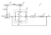
- FIG. 1 is a block diagram of a control system according to the present embodiment.
- FIG. 2 is a diagram for explaining a change in a set value.
- FIG. 3 is a block diagram of a control system according to a modification of the present embodiment.
- FIG. 4 shows waveforms of set values and measured values in a control system according to a conventional control method.
- FIG. 5 shows a waveform when the set value is changed by the set value changing unit in the control system according to the present embodiment.
- FIG. 6 shows waveforms when the set value is changed by the set value changing unit and the control parameter is changed by the adjusting unit in the control system according to the present embodiment.
- FIG. 1 is a block diagram of a control system according to the present embodiment.
- the control system 1 includes a set value change unit (SV change unit) 10, a PID control device 20, and a control target 40.
- the control system 1 may further include an adjustment unit 50. Further, the control system 1 may further include a limiter 30.
- the control system 1 forms a feedback control system as shown in FIG.
- the PID controller 20 controls the control target 40 by setting parameters of a proportional element (proportional band, P) 20a, an integral element (integral time, I) 20b, and a differential element (differential time, D) 20c.
- P proportional element
- I integral element
- D differential element
- the PID control device 20 controls the measured value (PV) output from the control target 40 and measured by an appropriate measuring device to be a given set value (SV).
- SV set value
- the set value may be referred to as a target value.
- the limiter 30 limits the amount of operation input to the control target 40. For example, the limiter 30 outputs the upper limit value to the control target 40 when the operation amount output from the PID control device 20 exceeds a preset upper limit value, and outputs the lower limit value when the operation amount is lower than the lower limit value. The value is output to the control target 40.
- the control target 40 is a target controlled by the PID control device 20.
- the temperature of a desired portion of the control target 40 may be controlled.
- An appropriate device can be used as the control target 40, and the measured value (PV) to be controlled may be an appropriate physical quantity.
- the measured value is mainly a temperature will be described.
- the set value changing unit 10 changes the set value when a trigger signal is input from the outside.
- the set value changing unit 10 changes the set value by a predetermined amount for a predetermined time in a direction opposite to the direction in which the measured value changes.
- the trigger signal is input to the set value changing unit 10 when the measured value changes by a predetermined threshold or more in a state where the measured value is stable at or near the set value, for example.
- the stable state near the set value refers to a state where the measured value is not exactly equal to the set value but is within a predetermined allowable error range.
- the set value changing unit 10 itself may detect that the measured value has changed by a predetermined threshold or more. Such a change in the set value is caused, for example, by an object or a material coming into contact with or approaching the control target, or by other appropriate disturbance.
- FIG. 2 is a diagram for explaining a change in a set value.
- the set value changing unit 10 changes the set value as shown by a solid line 101 in the figure.
- the amount of change of the set value (change amount of set value, change width) 102 can be determined based on the proportional band of the PID control.
- the change amount 102 of the set value is the first coefficient times the proportional band of the PID control.
- the first coefficient ⁇ is predetermined and may be, for example, a value larger than 0 and smaller than 1. In other words, the change amount 102 of the set value is smaller than the value of the proportional band.
- the direction in which the set value is changed is opposite to the direction in which the measured value changes.
- the set value changing unit 10 adds the change amount 102 to a predetermined set value when the measured value changes in a decreasing direction, and in advance, when the measured value changes in a increasing direction, The change amount is subtracted from the determined set value (SV in FIG. 1). Note that subtracting the change amount is synonymous with adding a negative change amount.
- the measured value decreases (for example, the temperature drops) by changing the set value in this way, the measured value decrease amount is reduced, while the measured value increases (for example, the temperature rises). ), The amount of increase in the measured value is reduced. Further, since the change of the set value is performed, for example, by a trigger signal generated at a timing when the change of the measured value is detected, an effect can be obtained in a short time even in a system having a long dead time.
- the time 103 for changing the set value can be determined based on the integration time of the PID control.
- the time 103 for changing the set value is a second coefficient times the integration time of the PID control, and the second coefficient ⁇ is predetermined and can be set to a value larger than 0 and smaller than 1, for example.
- the set value changing unit 10 After the change time elapses, the set value changing unit 10 returns the set value to a predetermined initial set value (SV in FIG. 1).
- the adjustment unit 50 may change each parameter of the PID control.
- the operation of the adjusting unit 50 is executed by inputting a trigger signal from the outside, similarly to the setting value changing unit 10 (104 in FIG. 2).
- the trigger signal input to the adjusting unit 50 can be the same as the trigger signal input to the set value changing unit 10.
- the adjustment unit 50 operates when the measured value changes by a predetermined threshold or more in a state where the measured value is stable at the set value or near the measured value.
- the adjusting unit 50 performs one or more of (a) narrowing the proportional band in the PID control, (b) increasing the integration time, and (c) increasing the differentiation time.
- the proportional band, the integration time, and the differentiation time are determined by the appropriate control system design method according to the control target, and are set in the PID control device 20.
- the adjusting unit 50 changes the proportional band in the PID control to a third coefficient times the proportional band.
- the third coefficient ⁇ is predetermined and may be, for example, a value larger than 0.1 and smaller than 1.
- the adjustment unit 50 changes the integration time in the PID control to a fourth coefficient times the integration time.
- the fourth coefficient ⁇ is predetermined and may be, for example, a value larger than 1 and smaller than 1.5.
- the adjustment unit 50 changes the derivative time in the PID control to a fifth coefficient times the derivative time.
- the fifth coefficient ⁇ is predetermined and may be, for example, a value greater than 1 and less than 1.5.
- FIG. 3 is a block diagram of a control system 2 according to a modification of the present embodiment.
- the control system 2 includes a detection unit 60 in addition to the control system 1 described above.
- the detection unit 60 monitors the measured value and the set value, and detects that the measured value has changed by a predetermined threshold or more in a state where the measured value is stable at or near the set value.
- the detecting unit 60 provides a trigger signal to the set value changing unit 10.
- Other configurations are the same as those of the control system 1 described above, and thus detailed description will be omitted.
- the measured value when the measured value changes, the measured value can be made to converge to the set value while reducing the difference between the measured value and the set value.
- the measured value decreases, the amount of change in the measured value up to a position (bottom) on the waveform where the measured value starts to increase can be reduced.
- the present embodiment is particularly effective for a system having a long dead time. According to the present embodiment, even if the system has a long dead time, the change in the measured value can be improved in response to the change in the measured value at an early stage.
- the system having a long dead time is, for example, a system in which L: T is 1:10 or 1: 5 when the dead time of the system is represented by L and the time constant is represented by T.
- the present invention is not limited to this.
- the rise of the manipulated variable can be quickened in response to a change in the measured value, and the manipulated variable having an upper limit can be used efficiently.
- the time until the measured value converges may be longer than expected.
- the manipulated variable rises at the maximum to the upper limit value, so that the subsequent manipulated variable saturation can be avoided, and the time until the measured value converges can be prevented from becoming long.
- FIGS. 4 to 6 are diagrams showing simulation results of the control system in the present embodiment.
- FIG. 4 shows waveforms of a set value 31 and a measured value 32 in a control system using a conventional control method as a comparison target.
- the waveform in FIG. 4 is a waveform in a control system that does not include the setting value change unit 10 and the adjustment unit 50 in the present embodiment, and the detection unit 60 in the above-described modification.
- the measured value is temperature and the set value is 200 degrees. In a state where the measured value was stabilized at the set value of 200 degrees, the temperature was lowered by giving disturbance.
- the set value (original set value) when the set value is changed by the set value changing unit 10 is indicated by a broken line, and the waveform of the measured value is indicated by a solid line.
- the set value is changed by the set value changing unit 10, and FIG. 5 shows the set value (SV in FIG. 1) input to the set value changing unit 10.
- FIG. 5 shows a case where the first coefficient ⁇ for obtaining the change amount (change width) 102 of the set value and the second coefficient ⁇ for obtaining the change time 103 of the set value are set to various values.
- Each waveform is shown. For example, respective waveforms when the first coefficient ⁇ is 0.10, 0.25, 0.50, and 0.80, and the second coefficient ⁇ is 0.25 and 0.50 are shown.
- the position of the bottom of the measured value (the minimum value of the measured value) is improved as compared with the example of FIG.
- the drop width of the measured value is smaller than that in FIG.
- the first coefficient ⁇ for obtaining the change amount (change width) of the set value 102 is 0.1 or 0.25
- the first coefficient ⁇ is 0.5 or 0.8
- the second coefficient ⁇ for obtaining the change time 103 is 0.25
- the amplitude of the overshoot is also reduced as compared with the example of FIG. In other words, both the drop width of the measured value and the amplitude of the overshoot are small, and the fluctuation width of the measured value is reduced.
- the amplitude of the overshoot increases as the second coefficient ⁇ increases.
- the amplitude of the overshoot is larger than that of the example of FIG. 4, but the amplitude of the overshoot is smaller than the measured value drop width of the example of FIG.
- the absolute value of the difference (deviation) between the set values is smaller than in the example of FIG. In other words, the fluctuation range of the measured value is reduced.
- the set values (original set values) when the set values are changed by the set value changing unit 10 and the control parameters are changed by the adjusting unit 50 are indicated by broken lines.
- the waveform of the measured value is shown by a solid line.
- the adjustment unit 50 sets the third coefficient ⁇ for changing the proportional band to 0.6, the fourth coefficient ⁇ for changing the integration time, and the fifth coefficient ⁇ for changing the differentiation time.
- the coefficient ⁇ is set to 1.4.
- the adjusting section 50 changes the proportional band to 0.6 times the set proportional band, and changes the integration time and derivative time to 1.4 times the set integral time and derivative time. It is an example. Also, as in FIG.
- the first coefficient ⁇ for obtaining the change amount (change width) of the set value is set to 0.10, 0.25, 0.50, 0.80, and the change time of the set value is obtained.
- the above-described set value change unit 10, adjustment unit 50, and detection unit 60 can also be realized by a computer having a processing unit and a storage unit.
- the processing unit executes each processing of the setting value changing unit 10, the adjusting unit 50, and the detecting unit 60.
- the storage unit stores a program executed by the processing unit.
- the above-described processing can also be realized as a control method, a set value changing method, and a control parameter changing method executed by the processing unit. Further, the present invention can be realized by a program or a program medium including instructions for causing the processing unit to execute the above-described processing, a computer-readable recording medium storing the program, a non-transitory recording medium, and the like.
- the present invention is applicable to industries that use a control system that performs PID control, such as a device that controls temperature by PID control.
Landscapes
- Physics & Mathematics (AREA)
- General Physics & Mathematics (AREA)
- Engineering & Computer Science (AREA)
- Automation & Control Theory (AREA)
- Feedback Control In General (AREA)
Priority Applications (4)
| Application Number | Priority Date | Filing Date | Title |
|---|---|---|---|
| CN201880095025.0A CN112368651A (zh) | 2018-06-27 | 2018-06-27 | 控制装置以及控制方法 |
| PCT/JP2018/024360 WO2020003403A1 (ja) | 2018-06-27 | 2018-06-27 | 制御装置及び制御方法 |
| JP2020526774A JPWO2020003403A1 (ja) | 2018-06-27 | 2018-06-27 | 制御装置及び制御方法 |
| KR1020217002667A KR20210024128A (ko) | 2018-06-27 | 2018-06-27 | 제어장치 및 제어방법 |
Applications Claiming Priority (1)
| Application Number | Priority Date | Filing Date | Title |
|---|---|---|---|
| PCT/JP2018/024360 WO2020003403A1 (ja) | 2018-06-27 | 2018-06-27 | 制御装置及び制御方法 |
Publications (1)
| Publication Number | Publication Date |
|---|---|
| WO2020003403A1 true WO2020003403A1 (ja) | 2020-01-02 |
Family
ID=68986677
Family Applications (1)
| Application Number | Title | Priority Date | Filing Date |
|---|---|---|---|
| PCT/JP2018/024360 WO2020003403A1 (ja) | 2018-06-27 | 2018-06-27 | 制御装置及び制御方法 |
Country Status (4)
| Country | Link |
|---|---|
| JP (1) | JPWO2020003403A1 (zh) |
| KR (1) | KR20210024128A (zh) |
| CN (1) | CN112368651A (zh) |
| WO (1) | WO2020003403A1 (zh) |
Cited By (1)
| Publication number | Priority date | Publication date | Assignee | Title |
|---|---|---|---|---|
| CN111708391A (zh) * | 2020-06-18 | 2020-09-25 | 浙江鲜达环保科技有限公司 | 一种温度控制方法、系统及计算机可读存储介质 |
Citations (4)
| Publication number | Priority date | Publication date | Assignee | Title |
|---|---|---|---|---|
| JPH0527802A (ja) * | 1991-07-17 | 1993-02-05 | Rika Kogyo Kk | 調節計 |
| JP2015084155A (ja) * | 2013-10-25 | 2015-04-30 | オムロン株式会社 | パラメータ調整装置、パラメータ調整方法およびパラメータ調整プログラム |
| WO2017085781A1 (ja) * | 2015-11-17 | 2017-05-26 | 理化工業株式会社 | 温度制御装置及び温度制御方法 |
| JP2018095351A (ja) * | 2016-12-09 | 2018-06-21 | ダイヤモンドエンジニアリング株式会社 | 粉体供給装置 |
Family Cites Families (5)
| Publication number | Priority date | Publication date | Assignee | Title |
|---|---|---|---|---|
| JPH07104681B2 (ja) * | 1988-03-18 | 1995-11-13 | 株式会社東芝 | プロセス制御装置 |
| JPH0580804A (ja) * | 1991-09-20 | 1993-04-02 | Yokogawa Electric Corp | 調節計 |
| JP2006260047A (ja) * | 2005-03-16 | 2006-09-28 | Yamatake Corp | 時間比例制御装置 |
| CN100565413C (zh) * | 2008-01-30 | 2009-12-02 | 北京英华达电力电子工程科技有限公司 | 一种温度调节的方法和装置 |
| JP5627106B2 (ja) * | 2011-02-16 | 2014-11-19 | アズビル株式会社 | 制御装置および制御方法 |
-
2018
- 2018-06-27 KR KR1020217002667A patent/KR20210024128A/ko not_active Application Discontinuation
- 2018-06-27 WO PCT/JP2018/024360 patent/WO2020003403A1/ja active Application Filing
- 2018-06-27 JP JP2020526774A patent/JPWO2020003403A1/ja active Pending
- 2018-06-27 CN CN201880095025.0A patent/CN112368651A/zh active Pending
Patent Citations (4)
| Publication number | Priority date | Publication date | Assignee | Title |
|---|---|---|---|---|
| JPH0527802A (ja) * | 1991-07-17 | 1993-02-05 | Rika Kogyo Kk | 調節計 |
| JP2015084155A (ja) * | 2013-10-25 | 2015-04-30 | オムロン株式会社 | パラメータ調整装置、パラメータ調整方法およびパラメータ調整プログラム |
| WO2017085781A1 (ja) * | 2015-11-17 | 2017-05-26 | 理化工業株式会社 | 温度制御装置及び温度制御方法 |
| JP2018095351A (ja) * | 2016-12-09 | 2018-06-21 | ダイヤモンドエンジニアリング株式会社 | 粉体供給装置 |
Cited By (1)
| Publication number | Priority date | Publication date | Assignee | Title |
|---|---|---|---|---|
| CN111708391A (zh) * | 2020-06-18 | 2020-09-25 | 浙江鲜达环保科技有限公司 | 一种温度控制方法、系统及计算机可读存储介质 |
Also Published As
| Publication number | Publication date |
|---|---|
| JPWO2020003403A1 (ja) | 2021-07-08 |
| CN112368651A (zh) | 2021-02-12 |
| KR20210024128A (ko) | 2021-03-04 |
Similar Documents
| Publication | Publication Date | Title |
|---|---|---|
| JP6165585B2 (ja) | プラント制御装置の制御ゲイン最適化システム | |
| JP2009165258A (ja) | ゲイン自動調整機能を備えたサーボモータ制御装置 | |
| KR20160047430A (ko) | 유량 제어 장치 및 유량 제어 프로그램 | |
| WO2016042589A1 (ja) | 制御装置 | |
| US20140121853A1 (en) | Feedback control method, feedback control apparatus, and feedback control program | |
| KR102384043B1 (ko) | 유체 제어 장치 및 유체 제어 장치용 프로그램 기록 매체 | |
| JP6220699B2 (ja) | 流量制御装置及び流量制御装置用プログラム | |
| JP2001117603A (ja) | 制御演算装置及び制御演算方法 | |
| WO2020003403A1 (ja) | 制御装置及び制御方法 | |
| KR102339509B1 (ko) | 질량 유량 제어 장치 | |
| US20160282829A1 (en) | Controller and control method | |
| JP6268012B2 (ja) | 比例ソレノイドバルブの制御方法 | |
| CN107102555B (zh) | 一种镇定一阶惯性加纯滞后系统的线性自抗扰控制器设计方法 | |
| US10120349B2 (en) | Control device and control method | |
| JP4648448B2 (ja) | Pid調節器を含む閉ループ系のプロセス制御装置 | |
| Kurien et al. | Overview of different approaches of pid controller tuning | |
| KR20200115144A (ko) | 제어 장치 및 제어 방법 | |
| JP2009187180A (ja) | 制御機器および制御方法 | |
| JPWO2008018496A1 (ja) | 制御方法および制御装置 | |
| US11237532B2 (en) | Hysteresis compensation control of an actuator | |
| WO2022034658A1 (ja) | 制御装置 | |
| KR101572241B1 (ko) | 강건한 제어 성능을 갖는 제어시스템 | |
| KR102043328B1 (ko) | 제어 장치, 제어 방법, 제어 프로그램 | |
| JP2020187522A (ja) | 制御選択調節装置 | |
| US9582754B1 (en) | Adaptive feed forward method for temperature control |
Legal Events
| Date | Code | Title | Description |
|---|---|---|---|
| 121 | Ep: the epo has been informed by wipo that ep was designated in this application |
Ref document number: 18924252 Country of ref document: EP Kind code of ref document: A1 |
|
| ENP | Entry into the national phase |
Ref document number: 2020526774 Country of ref document: JP Kind code of ref document: A |
|
| NENP | Non-entry into the national phase |
Ref country code: DE |
|
| ENP | Entry into the national phase |
Ref document number: 20217002667 Country of ref document: KR Kind code of ref document: A |
|
| 122 | Ep: pct application non-entry in european phase |
Ref document number: 18924252 Country of ref document: EP Kind code of ref document: A1 |