WO2019244722A1 - 情報処理装置 - Google Patents
情報処理装置 Download PDFInfo
- Publication number
- WO2019244722A1 WO2019244722A1 PCT/JP2019/023142 JP2019023142W WO2019244722A1 WO 2019244722 A1 WO2019244722 A1 WO 2019244722A1 JP 2019023142 W JP2019023142 W JP 2019023142W WO 2019244722 A1 WO2019244722 A1 WO 2019244722A1
- Authority
- WO
- WIPO (PCT)
- Prior art keywords
- pairing
- information
- information processing
- terminal
- unit
- Prior art date
- Legal status (The legal status is an assumption and is not a legal conclusion. Google has not performed a legal analysis and makes no representation as to the accuracy of the status listed.)
- Ceased
Links
Images


Classifications
-
- H—ELECTRICITY
- H04—ELECTRIC COMMUNICATION TECHNIQUE
- H04L—TRANSMISSION OF DIGITAL INFORMATION, e.g. TELEGRAPHIC COMMUNICATION
- H04L65/00—Network arrangements, protocols or services for supporting real-time applications in data packet communication
- H04L65/1066—Session management
- H04L65/1069—Session establishment or de-establishment
-
- H—ELECTRICITY
- H04—ELECTRIC COMMUNICATION TECHNIQUE
- H04L—TRANSMISSION OF DIGITAL INFORMATION, e.g. TELEGRAPHIC COMMUNICATION
- H04L65/00—Network arrangements, protocols or services for supporting real-time applications in data packet communication
- H04L65/1066—Session management
- H04L65/1073—Registration or de-registration
-
- H—ELECTRICITY
- H04—ELECTRIC COMMUNICATION TECHNIQUE
- H04W—WIRELESS COMMUNICATION NETWORKS
- H04W4/00—Services specially adapted for wireless communication networks; Facilities therefor
- H04W4/80—Services using short range communication, e.g. near-field communication [NFC], radio-frequency identification [RFID] or low energy communication
-
- H—ELECTRICITY
- H04—ELECTRIC COMMUNICATION TECHNIQUE
- H04W—WIRELESS COMMUNICATION NETWORKS
- H04W76/00—Connection management
- H04W76/10—Connection setup
- H04W76/14—Direct-mode setup
-
- H—ELECTRICITY
- H04—ELECTRIC COMMUNICATION TECHNIQUE
- H04W—WIRELESS COMMUNICATION NETWORKS
- H04W8/00—Network data management
- H04W8/005—Discovery of network devices, e.g. terminals
-
- H—ELECTRICITY
- H04—ELECTRIC COMMUNICATION TECHNIQUE
- H04W—WIRELESS COMMUNICATION NETWORKS
- H04W84/00—Network topologies
- H04W84/18—Self-organising networks, e.g. ad-hoc networks or sensor networks
-
- H—ELECTRICITY
- H04—ELECTRIC COMMUNICATION TECHNIQUE
- H04W—WIRELESS COMMUNICATION NETWORKS
- H04W92/00—Interfaces specially adapted for wireless communication networks
- H04W92/16—Interfaces between hierarchically similar devices
- H04W92/18—Interfaces between hierarchically similar devices between terminal devices
Definitions
- the present invention relates to an information processing device.
- Bluetooth registered trademark
- pairing information necessary for wireless connection of a Bluetooth (registered trademark) device (hereinafter, referred to as an “advertising packet”) is registered in a Bluetooth (registered trademark) device that is a wireless connection partner. This enables recognition of Bluetooth (registered trademark) devices.
- Patent Literature 1 describes a technology of an information processing apparatus that performs broadcast communication by BLE while including a unique identifier (IDm) in an advertising packet.
- Patent Literature 2 discloses a technology regarding a communication device that controls BLE based on an event.
- BLE devices when there are a plurality of devices (hereinafter, referred to as “BLE devices”) to be wirelessly connected by BLE, the following problem occurs. That is, in the case of the conventional technology, as shown in FIG. 7, when there are BLE devices B and C to be connected to the BLE device A, for example, each of the BLE devices B and C transmits an advertising packet (see FIG. 7). 7), are transmitted at regular intervals. On the other hand, the BLE device A performs scanning for acquiring the transmitted advertising packet at regular intervals. Here, when the transmission timing of the advertising packet of each of the BLE devices B and C and the scan timing of the BLE device A overlap, the BLE device A detects the BLE devices B and C.
- Pairing with C becomes possible. Specifically, as a result of the scan of the BLE device A, information on each of the BLE devices B and C is displayed on the screen of the BLE device A. Then, when the user operating the BLE device A selects one of the BLE devices (B or C) to be paired with the BLE device A, the user selects the BLE device (B or C) and the BLE device A. Is performed for pairing.
- each of the information on the two BLE devices displayed on the screen of the BLE device A indicates which BLE device. It is difficult to determine whether the information is information.
- the present invention has been made in view of such a situation, and an object of the present invention is to make it possible to determine a pairing partner from a plurality of devices.
- an information processing device of one embodiment of the present invention An information processing apparatus for performing information communication with one or more other information processing apparatuses each performing a predetermined function, Pairing transmitted from the one other information processing device, triggered by the fact that information capable of identifying one other information processing device among the one or more other information processing devices is obtained as the specific information.
- a pairing unit that starts a process of acquiring information necessary for the device as pairing information, and performs pairing with the one other information processing device using the acquired pairing information; Is provided.
- an information processing device of another embodiment of the present invention includes: An information processing device that performs information communication with another information processing device to exhibit a predetermined function, Triggered by the fact that the information capable of identifying the information processing device is acquired by the other information processing device as the identification information, information necessary for pairing performed in the other information processing device is paired. Pairing means for executing control for transmitting to the other information processing device as information, Is provided.
- FIG. 1 is a block diagram illustrating a configuration of an information processing system including a central terminal according to an embodiment of the information processing device of the present invention.
- FIG. 2 is a block diagram illustrating a hardware configuration of a central terminal in FIG. 1.
- FIG. 11 is a block diagram showing a hardware configuration of a peripheral terminal according to another embodiment of the information processing device of the present invention.
- FIG. 4 is a functional block diagram illustrating an example of a functional configuration of a central terminal in FIG. 2 and a peripheral terminal in FIG. 3.
- FIG. 9 is a diagram illustrating a specific example of pairing performed between a central terminal and a peripheral terminal.
- FIG. 6 is a diagram showing a specific example of pairing that solves the problem of pairing shown in FIG. 5.
- FIG. 9 is a diagram showing a specific example of a pairing of a conventional technique performed between a central terminal and a peripheral terminal.
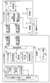
- FIG. 1 is a block diagram illustrating a configuration of an information processing system including a central terminal 1 according to an embodiment of the information processing apparatus of the present invention.
- the information processing system shown in FIG. 1 includes at least a central terminal 1 used by a user, and m peripheral terminals 2-1 to 2-m (m is an arbitrary integer value of 1 or more). Further, the information processing system shown in FIG. 1 includes functional modules 3-1 to 3-m as necessary.
- peripheral terminal 2 when it is not necessary to individually distinguish each of the peripheral terminals 2-1 to 2-m, these are collectively referred to as "peripheral terminal 2".
- functional module 3 When it is not necessary to distinguish the functional modules 3-1 to 3-m individually, these are collectively referred to as “functional module 3”.
- the peripheral terminal 2 is a hardware device used by being connected to the functional module 3, and performs pairing with the central terminal 1 by short-range wireless communication.
- the term “pairing” refers to causing the central terminal 1 to recognize the type and connection state of the peripheral terminal 2 and the functional modules 3 connected thereto using short-range wireless communication.
- the pairing in the BLE refers to a process of registering the advertising packet transmitted from the peripheral terminal 2-K to be wirelessly connected to the central terminal 1 with the central terminal 1 as described above. . In the following description, it is assumed that pairing in BLE is performed.
- the central terminal 1 performs pairing with a predetermined peripheral terminal 2-K (K is an arbitrary integer value from 1 to m), and thereby the peripheral terminal 2-K and the peripheral terminal 2-K are connected to each other. It recognizes the connected predetermined function module 3-K.
- the functional module 3-K is, for example, a hardware device including various sensors such as a temperature sensor, operating instruments such as a buzzer, and driving instruments such as a motor and a fan.
- FIG. 2 is a block diagram showing a hardware configuration of the central terminal 1 of FIG.
- the central terminal 1 is configured by a predetermined hardware device or the like.
- the central terminal 1 includes a CPU (Central Processing Unit) 21, a ROM (Read Only Memory) 22, a RAM (Random Access Memory) 23, a bus 24, an input / output interface 25, a touch operation input unit 26, and a display.
- Unit 27 an input unit 28, a storage unit 29, a first short-range wireless communication unit 30, a second short-range wireless communication unit 31, a communication unit 32, a drive 33, and a removable medium 34. I have.
- the CPU 21 executes various processes according to a program recorded in the ROM 22 or a program loaded from the storage unit 29 to the RAM 23.
- the RAM 23 also appropriately stores information necessary for the CPU 21 to execute various processes.
- the CPU 21, the ROM 22, and the RAM 23 are connected to each other via a bus 24.
- the bus 24 is also connected to an input / output interface 25.
- the input / output interface 25 includes a touch operation input unit 26, a display unit 27, an input unit 28, a storage unit 29, a first short-range wireless communication unit 30, a second short-range wireless communication unit 31, a communication unit 32, and a drive 33. It is connected.
- the touch operation input unit 26 is configured by, for example, a capacitive or resistive (pressure-sensitive) position input sensor stacked on the display unit 27, and detects the coordinates of the position where the touch operation is performed.
- the display unit 27 is configured by a display such as a liquid crystal, and displays various images such as an image related to program creation.
- the touch operation input unit 26 and the display unit 27 constitute a touch panel.
- the input unit 28 is configured by various hardware and the like, and inputs various information according to a user's instruction operation.
- the storage unit 29 includes a hard disk, a DRAM (Dynamic Random Access Memory), and the like, and stores various information.
- the first short-range wireless communication unit 30 executes, for example, control for performing short-range wireless communication by a method according to the NFC (registered trademark) standard.
- the second short-range wireless communication unit 31 executes, for example, control for performing short-range wireless communication by a method according to the standard of BLE (Bluetooth (registered trademark) Low Energy).
- BLE Bluetooth (registered trademark) Low Energy
- the central terminal 1 and the peripheral terminal 2 perform pairing by short-range wireless communication in a method according to the BLE standard.
- the communication unit 32 controls communication performed with another device via the Internet or the like independently of the first short-range wireless communication unit 30 and the second short-range wireless communication unit 31.
- the drive 33 is provided as needed.
- the drive 33 is appropriately equipped with a removable medium 34 made of a magnetic disk, an optical disk, a magneto-optical disk, a semiconductor memory, or the like.
- the program read from the removable medium 34 by the drive 33 is installed in the storage unit 29 as needed. Further, the removable medium 34 can also store various information stored in the storage unit 29 in the same manner as the storage unit 29.
- FIG. 3 is a block diagram showing a hardware configuration of the peripheral terminal 2 according to another embodiment of the information processing apparatus according to the present invention.
- the peripheral terminal 2 is configured by a predetermined hardware device or the like.
- the peripheral terminal 2 includes a CPU 41, a ROM 42, a RAM 43, a bus 44, a first short-range wireless communication unit 45, a second short-range wireless communication unit 46, a connection unit 47, and a power supply unit 48. I have.
- the CPU 41, the ROM 42, the RAM 43, the bus 44, the first short-range wireless communication unit 45, and the second short-range wireless communication unit 46 are basically the same as the configuration of the central terminal 1. Here, the description thereof is omitted.
- connection unit 47 makes a connection with another hardware device (for example, the functional module 3 in FIG. 1).
- the connection method by the connection unit 47 is not particularly limited, and the connection may be performed by a method in accordance with, for example, a LAN (Local Area Network) standard.
- the connection unit 47 receives power supplied from a power supply unit 48 described later and transmits power to another hardware device.
- the power supply unit 48 is a battery such as a battery.
- the power supply unit 48 supplies power to the peripheral terminal 2 and also supplies power to the functional module 3 via the connection unit 47 as appropriate.
- the functional module 3 of the information processing system of FIG. 1 also has the hardware configuration shown in FIG.
- the wireless connection processing refers to processing for wirelessly connecting the peripheral terminal 2 to the central terminal 1.
- FIG. 4 is a functional block diagram showing an example of a functional configuration of the central terminal 1 of FIG. 2 and the peripheral terminal 2 of FIG.
- the pairing unit 101 uses the first short-range wireless communication unit 30 to perform wireless communication with the central terminal 1 as a trigger, and performs pairing between the central terminal 1 and the peripheral terminal 2 via the second short-range wireless communication unit 31. Do.
- the pairing unit 101 includes a reading control unit 111, a detection unit 112, a pairing execution unit 113, and a connection confirmation unit 114.
- the read control unit 111 executes control for reading information (hereinafter, referred to as “individual identification information”) for uniquely identifying one of the peripheral terminals 2-1 to 2-m. Specifically, the reading control unit 111 executes control for reading the individual identification information of one peripheral terminal 2 by NFC (registered trademark) short-range wireless communication via the first short-range wireless communication unit 30.
- individual identification information hereinafter, referred to as “individual identification information”
- NFC registered trademark
- the detection unit 112 detects that the read control unit 111 has read the individual identification information of the peripheral terminal 2.
- the pairing execution unit 113 acquires the advertising packet transmitted from the peripheral terminal 2 by the BLE short-range wireless communication via the second short-range wireless communication unit 31 using the detection by the detection unit 112 as a trigger, and Pairing is performed with one peripheral terminal 2 from which the identification information has been read.
- connection confirmation unit 114 confirms the type and connection status of the peripheral terminal 2 paired with the central terminal 1 and the function module 3 connected thereto.
- the program creation unit 102 receives a user's touch operation and actually creates a program.
- the program causes the function module 3 connected to the paired peripheral terminal 2 to perform a predetermined function.
- the program execution unit 103 extracts a program that the user wants to execute from the programs created by the program creation unit 102 and executes the program. That is, the program execution unit 103 transmits the execution result (command or the like) of the created program to the peripheral terminal 2 and the function module 3, and causes the function module 3 to perform its function.
- the display control unit 104 performs control for displaying various information and the like on the display unit 27.
- the display control unit 104 can execute control to cause the display unit 27 to display the type of the functional module 3 and the connection status confirmed by the connection confirmation unit 114.
- the communication control unit 105 performs control for transmitting various types of information to the peripheral terminal 2 via the first short-range wireless communication unit 30 or the second short-range wireless communication unit 31.
- the pairing unit 201 uses the first short-range wireless communication unit 45 to perform wireless communication with the central terminal 1 as a trigger, and the second short-range wireless communication unit 46 performs communication with the central terminal 1 in BLE. Perform pairing.
- the terminal communication control unit 202 executes control for acquiring various information transmitted from the central terminal 1 via the second short-range wireless communication unit 46.
- the function module communication control unit 203 controls communication with the function module 3 when the peripheral terminal 2 and the function module 3 are connected via the connection unit 47.
- the main control unit 204 performs main control of various processes executed by the peripheral terminal 2.
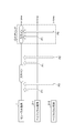
- FIG. 5 is a diagram illustrating a specific example of the pairing performed between the central terminal 1 and the peripheral terminal 2.
- the pairing of the example of FIG. 6 is executed instead of the pairing of the example of FIG.
- white arrows indicate advertising packets.
- pairing is performed by receiving and registering the advertising packet output from the peripheral terminal 2 at the central terminal 1.
- the central terminal 1 performs a scan at a predetermined interval to acquire an advertising packet.
- each of the peripheral terminals 2-1 and 2-2 transmits its own advertising packet.
- the central terminal 1 can perform pairing with the peripheral terminal 2.
- the central terminal 1 An advertising packet is obtained from each of the peripheral terminals 2-1 and 2-2.
- the central terminal 1 can detect that the two peripheral terminals 2-1 and 2-2 are present in the vicinity, but determine which is the peripheral terminal 2-1 and which is the peripheral terminal 2-2. It cannot be determined.
- the user may perform an operation of bringing one of the two peripheral terminals 2-1 and 2-2, for which pairing is desired (for example, the peripheral terminal 2-2), into contact with or close to the central terminal 1.
- the first short-range wireless communication unit 45 of the peripheral terminal 2-2 and the first short-range wireless communication unit 30 of the central terminal 1 perform short-range wireless communication using NFC (registered trademark).
- NFC registered trademark
- Such an event in which short-range wireless communication by NFC (registered trademark) is performed when the central terminal 1 and the peripheral terminal 2 (in this example, the peripheral terminal 2-2) come into contact with or approach each other is referred to as a “touch event”. Call. If the touch event is performed by the peripheral terminal 2-2, the central terminal 1 can determine that the peripheral terminal 2-2 is a pairing target.
- the advertising packet of the peripheral terminal 2-2 is transmitted after the touch event and during the scan of the central terminal 1. Need to be done. Therefore, if the scan timing of the central terminal 1 and the transmission timing of the advertising packet of the peripheral terminal 2-2 do not match well, a pair of the central terminal 1 and the peripheral terminal 2-2 is performed after the touch event is performed. It takes time before the ring is performed. That is, there is a first problem that the time for pairing becomes long.
- the advertising packet transmitted from the peripheral terminal 2-2 by lengthening the scan time by the central terminal 1 or shortening the scan interval. Good.
- the second problem of increased power consumption occurs because the time taken for scanning by the central terminal 1 is increased in total.
- the power consumption can be reduced by shortening the scanning time by the central terminal 1 in total, but the first problem occurs.
- the central terminal 1 may easily acquire the transmitted advertising packet by shortening the interval of transmitting the advertising packet by the peripheral terminal 2-2.
- the second problem of increasing power consumption occurs. If the time taken for pairing is increased to solve the second problem, the number of transmissions by the peripheral terminal 2-2 may be reduced in total, but the first problem occurs.
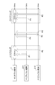
- FIG. 6 is a diagram illustrating a specific example of pairing that solves the pairing problem (a problem in which one of the first problem and the second problem occurs) illustrated in FIG. 5.
- the central terminal 1 starts scanning and the peripheral terminal 2-2 starts transmitting advertising. I do.
- the reading control unit 111 of the central terminal 1 executes control for reading the individual identification information of the peripheral terminal 2-2 that has become the partner of the touch event.
- the central terminal 1 immediately reads the individual identification information of the peripheral terminal 2-2.
- the pairing execution unit 113 starts scanning with the detection as a trigger.
- the pairing unit 201 of the peripheral terminal 2-2 similarly detects that the individual identification information has been read by the central terminal 1 due to a touch event, and transmits an advertising packet with this detection as a trigger. Thereby, the pairing unit 201 of the peripheral terminal 2-2 can immediately receive the advertising packet of the peripheral terminal 2-2 and execute the pairing almost in the same time as the touch event.
- the central terminal 1 is one of the two peripheral terminals 2 (in the example of FIG. 6, the peripheral terminals 2-1 and 2-2) of the same product, the one of the peripheral terminals 2 (the example of FIG. 6).
- the pairing with the peripheral terminal 2-2) can be instantaneously performed almost in time with the touch event. That is, the first problem is solved.
- the central terminal 1 starts scanning by using a touch event as a trigger without performing scanning at regular intervals, it is possible to save power required for scanning.
- the peripheral terminal 2 can start transmitting an advertising packet by using a touch event as a trigger without transmitting a packet at regular intervals, so that transmission of useless advertising packets that are not scanned can be suppressed, thereby saving power. can do. That is, the second problem is solved.
- the central terminal 1 performs only scanning
- the peripheral terminal 2 performs only packet transmission.
- the present invention is not limited to this configuration.
- the central terminal 1 and the peripheral terminal 2 may both be configured to perform both scanning and packet transmission. In this case, pairing can be performed more efficiently.
- the central terminal 1 recognizes the peripheral terminal 2 to be paired, and the event used as a trigger for starting the pairing is short-range wireless communication by NFC (NFC).
- NFC NFC
- a touch event using a combination of a reader and an NFC tag
- the present invention is not limited to this.
- a combination of a camera and a QR code registered trademark
- a combination of a Hall sensor and a magnet or a combination of an acceleration sensor and a vibration motor
- These combinations are combinations in which a trigger can be received in one direction from the former to the latter or from the latter to the former, but it is needless to say that the present invention is not particularly limited to this.
- a combination of an NFC reader and an NFC host card emulation device or a combination of a speaker and a microphone (or a microphone and a speaker) may be adopted. These combinations are combinations that can receive a trigger in both directions from the former to the latter and from the latter to the former.
- the pairing of the central terminal 1 and the peripheral terminal 2 is performed by short-range wireless communication according to the BLE standard, but the present invention is not particularly limited to this.
- the pairing is not limited to the short-range wireless communication, and the pairing may be performed by any means.
- the number of the peripheral terminals 2 and the number of the functional modules 3 are both described as m, but the present invention is not particularly limited to this. That is, the number of the peripheral terminals 2 and the number of the functional modules 3 may be the same or different. That is, s (s is an arbitrary integer of 1 or more) function modules 3 may be connected to one peripheral terminal 2.
- the above-described series of processing can be executed by hardware or can be executed by software.
- the functional configuration of FIG. 4 is merely an example, and is not particularly limited. That is, it suffices that the information processing system has a function capable of executing the above-described series of processing as a whole, and what kind of functional block is used to realize this function is not particularly limited to the example of FIG.
- the location of the functional block is not particularly limited to FIG. 4 and may be arbitrary.
- one functional block may be constituted by hardware alone, may be constituted by software alone, or may be constituted by a combination thereof.
- a program constituting the software is installed in a computer or the like from a network or a recording medium.
- the computer may be a computer embedded in dedicated hardware.
- the computer may be a computer that can execute various functions by installing various programs, for example, a general-purpose smartphone or a personal computer other than a server.
- a recording medium including such a program is not only constituted by a removable medium (not shown) distributed separately from the apparatus main body in order to provide the user with the program, but also a state in which the recording medium is pre-installed in the apparatus main body. And a recording medium provided to the user.
- steps for describing a program recorded on a recording medium are not limited to processing performed in chronological order according to the order, but are not necessarily performed in chronological order, but are performed in parallel or individually. This includes the processing to be executed. Also, in this specification, the term system refers to an entire device including a plurality of devices and a plurality of means.
- the information processing apparatus to which the present invention is applied can adopt various embodiments having the following configurations. That is, the information processing apparatus to which the present invention is applied (for example, the central terminal 1 in FIG. 3) In an information processing apparatus that performs information communication with one or more other information processing apparatuses (for example, the peripheral terminal 2 in FIG. 3) each performing a predetermined function, Among the one or more other information processing devices, information capable of specifying one other information processing device (for example, the peripheral terminal 2-2 in FIG. 6) has been acquired as specific information (for example, the above-described individual identification information).
- a pairing unit (for example, the pairing unit 101 in FIG. 4) that executes pairing with the one other information processing device using the acquired pairing information. Is provided.
- the information processing apparatus to which the present invention is applied (for example, the peripheral terminal 2 in FIG. 3, more specifically, for example, the peripheral terminal 2-2 in FIG. 6)
- An information processing device that performs information communication with another information processing device (for example, the central terminal 1 in FIG. 3) in order to perform a predetermined function,
- Another information processing device for example, the central terminal 1 in FIG. 3
- a pairing unit for example, the pairing unit 201 in FIG. 4
- a pairing unit that executes control for transmitting information necessary for the information processing to the other information processing apparatus as pairing information (for example, the above-described advertising packet) Is provided.
- the pairing can be performed in a short time and with low power consumption after the acquisition of the specific information (the touch event in the example of FIG. 6).
- Program creation 103 a program execution unit, 104, a display control unit, 105, a communication control unit, 111, a read control unit, 112, a detection unit, 113, a pairing execution unit, 114 ... Connection confirmation unit, 201 ... Pairing unit, 202 ... Terminal communication control unit, 203 ... Function module communication control unit, 204 ... Main control unit, 500 ... Advertising DB
Landscapes
- Engineering & Computer Science (AREA)
- Computer Networks & Wireless Communication (AREA)
- Signal Processing (AREA)
- Databases & Information Systems (AREA)
- Business, Economics & Management (AREA)
- General Business, Economics & Management (AREA)
- Multimedia (AREA)
- Mobile Radio Communication Systems (AREA)
- Telephone Function (AREA)
Priority Applications (5)
| Application Number | Priority Date | Filing Date | Title |
|---|---|---|---|
| KR1020217000361A KR102377849B1 (ko) | 2018-06-20 | 2019-06-11 | 정보 처리 장치 |
| CN201980041102.9A CN112335270A (zh) | 2018-06-20 | 2019-06-11 | 信息处理装置 |
| SG11202012720TA SG11202012720TA (en) | 2018-06-20 | 2019-06-11 | Information processing device |
| EP19821657.4A EP3806573A4 (en) | 2018-06-20 | 2019-06-11 | INFORMATION PROCESSING DEVICE |
| US17/254,611 US20210127247A1 (en) | 2018-06-20 | 2019-06-11 | Information processing device |
Applications Claiming Priority (2)
| Application Number | Priority Date | Filing Date | Title |
|---|---|---|---|
| JP2018-117367 | 2018-06-20 | ||
| JP2018117367A JP6861187B2 (ja) | 2018-06-20 | 2018-06-20 | 情報処理装置 |
Publications (1)
| Publication Number | Publication Date |
|---|---|
| WO2019244722A1 true WO2019244722A1 (ja) | 2019-12-26 |
Family
ID=68983338
Family Applications (1)
| Application Number | Title | Priority Date | Filing Date |
|---|---|---|---|
| PCT/JP2019/023142 Ceased WO2019244722A1 (ja) | 2018-06-20 | 2019-06-11 | 情報処理装置 |
Country Status (8)
| Country | Link |
|---|---|
| US (1) | US20210127247A1 (enExample) |
| EP (1) | EP3806573A4 (enExample) |
| JP (1) | JP6861187B2 (enExample) |
| KR (1) | KR102377849B1 (enExample) |
| CN (1) | CN112335270A (enExample) |
| SG (1) | SG11202012720TA (enExample) |
| TW (1) | TW202002581A (enExample) |
| WO (1) | WO2019244722A1 (enExample) |
Families Citing this family (3)
| Publication number | Priority date | Publication date | Assignee | Title |
|---|---|---|---|---|
| JP7589617B2 (ja) | 2021-03-26 | 2024-11-26 | セイコーエプソン株式会社 | 制御システムおよび印刷装置 |
| JP7718875B2 (ja) * | 2021-07-06 | 2025-08-05 | 任天堂株式会社 | 通信システム、通信装置、通信方法、および通信プログラム |
| KR102575048B1 (ko) * | 2021-10-29 | 2023-09-06 | 주식회사 지오플랜 | 멀티 ble 기반의 uwb 보안 레인징 방법 |
Citations (7)
| Publication number | Priority date | Publication date | Assignee | Title |
|---|---|---|---|---|
| JP2014068076A (ja) * | 2012-09-24 | 2014-04-17 | Sony Computer Entertainment Inc | 通信装置および通信方法 |
| JP2014138238A (ja) * | 2013-01-16 | 2014-07-28 | Nec Saitama Ltd | 携帯端末装置、無線通信装置、無線通信システム及び無線通信方法 |
| US20170026778A1 (en) * | 2015-07-21 | 2017-01-26 | VitaNet, Inc. | Selective Pairing of Wireless Devices Using Shared Keys |
| JP2017040910A (ja) * | 2015-08-20 | 2017-02-23 | スマート キッド エデュケイション リミテッド | 接続された玩具を使用する教育システム |
| JP2017208617A (ja) | 2016-05-16 | 2017-11-24 | リンナイ株式会社 | 通信装置 |
| JP2018023072A (ja) | 2016-08-05 | 2018-02-08 | 学校法人上智学院 | 呼出システム、呼出方法、情報処理装置、携帯端末及びそれらの制御方法 |
| WO2018155483A1 (ja) * | 2017-02-24 | 2018-08-30 | Vivita株式会社 | 制御装置、制御方法、情報処理装置、情報処理方法及びプログラム |
Family Cites Families (19)
| Publication number | Priority date | Publication date | Assignee | Title |
|---|---|---|---|---|
| JP2005303947A (ja) * | 2004-04-16 | 2005-10-27 | Matsushita Electric Ind Co Ltd | 無線通信装置および無線通信方法 |
| JP2007249425A (ja) * | 2006-03-14 | 2007-09-27 | Fujifilm Corp | 接続認証システム、通信装置、画像プリント装置又は画像データ記憶装置、制御プログラム、及び接続認証方法 |
| JP4981826B2 (ja) * | 2009-01-28 | 2012-07-25 | シャープ株式会社 | 通信システム、画像形成装置及び携帯情報端末装置 |
| US8432260B2 (en) * | 2010-02-26 | 2013-04-30 | GM Global Technology Operations LLC | Simplified vehicle bluetooth pairing employing near field communication tags |
| US8732319B2 (en) * | 2011-06-10 | 2014-05-20 | Qualcomm Incorporated | Context awareness proximity-based establishment of wireless communication connection |
| KR101811452B1 (ko) * | 2011-07-14 | 2017-12-22 | 주식회사 케이티 | Uicc 내부 애플리케이션을 이용한 uicc로의 접속 프로파일 등록방법, 그를 이용한 접속 프로파일 획득방법 및 p2p 전송방법과, 단말장치 |
| CN102723971B (zh) * | 2012-06-26 | 2014-09-24 | 宇龙计算机通信科技(深圳)有限公司 | 一种蓝牙设备及其蓝牙配对方法 |
| CN104602230B (zh) * | 2013-10-31 | 2019-06-18 | 深圳富泰宏精密工业有限公司 | 蓝牙通信装置及其使用方法 |
| US10045181B2 (en) * | 2013-11-11 | 2018-08-07 | Lg Electronics Inc. | Method and apparatus for Bluetooth connection |
| CN203734663U (zh) * | 2013-12-20 | 2014-07-23 | Tcl通力电子(惠州)有限公司 | 基于nfc的蓝牙配对电路 |
| KR102224156B1 (ko) * | 2014-04-02 | 2021-03-08 | 엘지전자 주식회사 | 이동 단말기 및 이의 제어방법 |
| US20160183317A1 (en) * | 2014-12-23 | 2016-06-23 | Intel Corporation | Method to reduce user perceived connection time for miracast/widi |
| CN104716994B (zh) * | 2015-01-09 | 2018-09-18 | 络达科技股份有限公司 | 磁控式蓝牙装置 |
| JP6606922B2 (ja) * | 2015-08-26 | 2019-11-20 | カシオ計算機株式会社 | 通信装置、時計及び通信方法 |
| US10896245B2 (en) * | 2016-08-29 | 2021-01-19 | Bigfoot Biomedical, Inc. | Network topology for insulin pump systems |
| US11032855B2 (en) * | 2016-10-18 | 2021-06-08 | Dexcom, Inc. | System and method for communication of analyte data |
| US10313003B2 (en) * | 2016-12-06 | 2019-06-04 | Brunswick Corporation | Systems and methods for wirelessly pairing a fitness machine to an accessory |
| CN107079256A (zh) * | 2016-12-30 | 2017-08-18 | 深圳市大疆灵眸科技有限公司 | 用于自动配对的方法和设备 |
| CN107979830B (zh) * | 2017-11-21 | 2020-11-27 | 大众问问(北京)信息科技有限公司 | 一种智能后视镜的蓝牙连接方法、装置、设备及存储介质 |
-
2018
- 2018-06-20 JP JP2018117367A patent/JP6861187B2/ja active Active
-
2019
- 2019-06-11 EP EP19821657.4A patent/EP3806573A4/en not_active Withdrawn
- 2019-06-11 SG SG11202012720TA patent/SG11202012720TA/en unknown
- 2019-06-11 WO PCT/JP2019/023142 patent/WO2019244722A1/ja not_active Ceased
- 2019-06-11 US US17/254,611 patent/US20210127247A1/en not_active Abandoned
- 2019-06-11 KR KR1020217000361A patent/KR102377849B1/ko active Active
- 2019-06-11 CN CN201980041102.9A patent/CN112335270A/zh active Pending
- 2019-06-17 TW TW108120881A patent/TW202002581A/zh unknown
Patent Citations (7)
| Publication number | Priority date | Publication date | Assignee | Title |
|---|---|---|---|---|
| JP2014068076A (ja) * | 2012-09-24 | 2014-04-17 | Sony Computer Entertainment Inc | 通信装置および通信方法 |
| JP2014138238A (ja) * | 2013-01-16 | 2014-07-28 | Nec Saitama Ltd | 携帯端末装置、無線通信装置、無線通信システム及び無線通信方法 |
| US20170026778A1 (en) * | 2015-07-21 | 2017-01-26 | VitaNet, Inc. | Selective Pairing of Wireless Devices Using Shared Keys |
| JP2017040910A (ja) * | 2015-08-20 | 2017-02-23 | スマート キッド エデュケイション リミテッド | 接続された玩具を使用する教育システム |
| JP2017208617A (ja) | 2016-05-16 | 2017-11-24 | リンナイ株式会社 | 通信装置 |
| JP2018023072A (ja) | 2016-08-05 | 2018-02-08 | 学校法人上智学院 | 呼出システム、呼出方法、情報処理装置、携帯端末及びそれらの制御方法 |
| WO2018155483A1 (ja) * | 2017-02-24 | 2018-08-30 | Vivita株式会社 | 制御装置、制御方法、情報処理装置、情報処理方法及びプログラム |
Non-Patent Citations (1)
| Title |
|---|
| See also references of EP3806573A4 |
Also Published As
| Publication number | Publication date |
|---|---|
| US20210127247A1 (en) | 2021-04-29 |
| TW202002581A (zh) | 2020-01-01 |
| EP3806573A1 (en) | 2021-04-14 |
| SG11202012720TA (en) | 2021-01-28 |
| EP3806573A4 (en) | 2021-08-04 |
| KR20210020076A (ko) | 2021-02-23 |
| JP6861187B2 (ja) | 2021-04-21 |
| CN112335270A (zh) | 2021-02-05 |
| JP2019220863A (ja) | 2019-12-26 |
| KR102377849B1 (ko) | 2022-03-22 |
Similar Documents
| Publication | Publication Date | Title |
|---|---|---|
| JP5898710B2 (ja) | 無線通信端末、その制御方法、及びそのプログラム | |
| JP6601188B2 (ja) | 電子機器、端末装置、無線ネットワーク切替え方法、無線通信接続方法、およびプログラム | |
| JP2010187089A5 (enExample) | ||
| WO2019244722A1 (ja) | 情報処理装置 | |
| EP3349094A1 (en) | Method for displaying content and electronic device thereof | |
| KR102489729B1 (ko) | 연결 정보에 기반하여 외부 장치들과 연결하는 전자 장치 및 그 동작 방법 | |
| JP6480677B2 (ja) | 通信装置及びその制御方法、コンピュータプログラム | |
| US20150335001A1 (en) | Electric Fishing Reel and Remote Operation System and Method | |
| WO2016017285A1 (ja) | 無線通信システムおよび無線通信方法 | |
| KR20210080937A (ko) | 전자 장치 및 전자 장치의 nan 기반의 통신 제어 방법 | |
| US20180324587A1 (en) | Authentication system, recording medium having recorded therein computer program controlling authentication system, and reader for use in authentication system | |
| JP2017050745A (ja) | 通信装置、制御方法及びプログラム | |
| KR102061166B1 (ko) | 센싱 방법 및 장치 | |
| CN111034232A (zh) | 通信系统、通信装置以及省电方法 | |
| US11212190B2 (en) | Communication apparatus and control method for the same | |
| US20180110083A1 (en) | Communications apparatus, control method, and storage medium | |
| JP2014204187A (ja) | 通信端末、画像形成装置及びその制御方法、並びにプログラム、通信システム | |
| US20150338925A1 (en) | Causing gesture responses on connected devices | |
| WO2018079063A1 (ja) | ネットワークシステム、サーバ、情報処理方法、空気調和機、およびプログラム | |
| JP6096497B2 (ja) | 通信プログラム、情報処理装置、通信システム、および通信方法 | |
| KR20230072205A (ko) | 가전 기기를 서버에 등록하는 장치 및 방법 | |
| JP2018029222A (ja) | 情報処理装置及びその制御方法、並びにプログラム | |
| EP3451686B1 (en) | Automatic logout method using bluetooth low energy communication and image forming apparatus for executing same | |
| JP2016186700A (ja) | 端末装置、制御システム、および制御プログラム | |
| KR101619317B1 (ko) | 부가 서비스를 제공하는 게스트 페이저와 그의 작동 방법 |
Legal Events
| Date | Code | Title | Description |
|---|---|---|---|
| 121 | Ep: the epo has been informed by wipo that ep was designated in this application |
Ref document number: 19821657 Country of ref document: EP Kind code of ref document: A1 |
|
| NENP | Non-entry into the national phase |
Ref country code: DE |
|
| ENP | Entry into the national phase |
Ref document number: 20217000361 Country of ref document: KR Kind code of ref document: A |
|
| ENP | Entry into the national phase |
Ref document number: 2019821657 Country of ref document: EP Effective date: 20210108 |