WO2019244249A1 - プラント用機器接続方法 - Google Patents
プラント用機器接続方法 Download PDFInfo
- Publication number
- WO2019244249A1 WO2019244249A1 PCT/JP2018/023318 JP2018023318W WO2019244249A1 WO 2019244249 A1 WO2019244249 A1 WO 2019244249A1 JP 2018023318 W JP2018023318 W JP 2018023318W WO 2019244249 A1 WO2019244249 A1 WO 2019244249A1
- Authority
- WO
- WIPO (PCT)
- Prior art keywords
- cable
- plant
- laying
- installation step
- sub
- Prior art date
- Legal status (The legal status is an assumption and is not a legal conclusion. Google has not performed a legal analysis and makes no representation as to the accuracy of the status listed.)
- Ceased
Links
Images










Classifications
-
- B—PERFORMING OPERATIONS; TRANSPORTING
- B63—SHIPS OR OTHER WATERBORNE VESSELS; RELATED EQUIPMENT
- B63B—SHIPS OR OTHER WATERBORNE VESSELS; EQUIPMENT FOR SHIPPING
- B63B73/00—Building or assembling vessels or marine structures, e.g. hulls or offshore platforms
- B63B73/20—Building or assembling prefabricated vessel modules or parts other than hull blocks, e.g. engine rooms, rudders, propellers, superstructures, berths, holds or tanks
-
- B—PERFORMING OPERATIONS; TRANSPORTING
- B63—SHIPS OR OTHER WATERBORNE VESSELS; RELATED EQUIPMENT
- B63B—SHIPS OR OTHER WATERBORNE VESSELS; EQUIPMENT FOR SHIPPING
- B63B35/00—Vessels or similar floating structures specially adapted for specific purposes and not otherwise provided for
- B63B35/44—Floating buildings, stores, drilling platforms, or workshops, e.g. carrying water-oil separating devices
-
- E—FIXED CONSTRUCTIONS
- E04—BUILDING
- E04H—BUILDINGS OR LIKE STRUCTURES FOR PARTICULAR PURPOSES; SWIMMING OR SPLASH BATHS OR POOLS; MASTS; FENCING; TENTS OR CANOPIES, IN GENERAL
- E04H5/00—Buildings or groups of buildings for industrial or agricultural purposes
- E04H5/02—Buildings or groups of buildings for industrial purposes, e.g. for power-plants or factories
-
- H—ELECTRICITY
- H02—GENERATION; CONVERSION OR DISTRIBUTION OF ELECTRIC POWER
- H02G—INSTALLATION OF ELECTRIC CABLES OR LINES, OR OF COMBINED OPTICAL AND ELECTRIC CABLES OR LINES
- H02G1/00—Methods or apparatus specially adapted for installing, maintaining, repairing or dismantling electric cables or lines
- H02G1/06—Methods or apparatus specially adapted for installing, maintaining, repairing or dismantling electric cables or lines for laying cables, e.g. laying apparatus on vehicle
-
- B—PERFORMING OPERATIONS; TRANSPORTING
- B63—SHIPS OR OTHER WATERBORNE VESSELS; RELATED EQUIPMENT
- B63J—AUXILIARIES ON VESSELS
- B63J3/00—Driving of auxiliaries
- B63J2003/001—Driving of auxiliaries characterised by type of power supply, or power transmission, e.g. by using electric power or steam
- B63J2003/002—Driving of auxiliaries characterised by type of power supply, or power transmission, e.g. by using electric power or steam by using electric power
Definitions
- the present invention relates to, for example, a plant device connection method for connecting various devices with cables in the construction of a plant for mining, producing, and refining oil, natural gas, and the like.
- the present invention relates to a plant device connection method capable of shortening the time.
- the cable laying operation is not started until the installation of the LER and the various devices is completed, and the cable laying operation is performed after the installation of the LER and the various devices.
- Such equipment connection work is not only for construction of land plants such as petroleum refining plants, petrochemical plants, and land natural gas liquefaction plants (LNG plants), but also for construction work of marine plants that mine and produce oil and natural gas at sea. The same is done.
- land plants such as petroleum refining plants, petrochemical plants, and land natural gas liquefaction plants (LNG plants)
- LNG plants land natural gas liquefaction plants
- Equipment used as a marine plant includes FPSO (Floating Production Storage and Offloading Equipment) for producing, storing and unloading petroleum and natural gas, and FSO (Floating Storage and Loading Equipment) for only storing and unloading without production equipment.
- FPSO Floating Production Storage and Offloading Equipment
- FSO Floating Storage and Loading Equipment
- Floating-type facilities such as an FSU (floating-type storage facility) that performs only storage and FLNG (floating-type liquefied natural gas production facility) specialized in production, storage, and unloading of liquefied natural gas are known.
- the hull is constructed and assembled, then the hull is launched and connected to the quay for outfitting.
- various devices such as an electric room in which power distribution equipment is stored, an instrument room in which instruments are stored, and a gas turbine for power generation are installed.
- An object of the present invention is to provide a plant device connection method capable of shortening a plant period by enabling commissioning to be started immediately after installation of various devices in the construction of a plant.
- the present invention includes the following items.
- a plant device connection method for connecting a plurality of devices by a cable in a plant construction A first installation step of installing a first device; A second installation step of installing a second device; A laying step of laying the cable, Connecting the cable and the second device, The second installation step is completed after completion of the first installation step; The laying step is completed before the completion of the second installation step; The plant connection method, wherein the connection step is performed after completion of the second installation step.
- the second installation step includes an arrangement step of arranging a sub-cable whose one end is connected to the second device such that the other end of the sub-cable is located at a laying height of the cable.
- At least one of the first device and the second device is arranged at a position separated from a construction reference plane of the plant in a height direction, any one of [1] to [3].
- the first device is a local electrical room
- the plant device connection method according to any one of [1] to [5], wherein the second device is installed in a state where the second device is installed in a module for plant construction.
- the second installation step includes a step of vertically hanging a sub-cable having one end connected to the second device from the module such that the other end of the sub-cable is positioned at a laying height of the cable.
- the first installation step and the second installation step are completed, the connection step can be performed, and the commissioning can be started immediately thereafter. For this reason, the time required from the installation of various devices to the start of commissioning can be reduced, and as a result, the construction period of the plant can be shortened.
- 2 is a Gantt chart for explaining a device connection method in the floating facility of FIG. 1.
- 6 is a Gantt chart for explaining another method of connecting devices in the floating facility of FIG. 1.
- 6 is a Gantt chart for explaining another method of connecting devices in the floating facility of FIG. 1.
- 6 is a Gantt chart for explaining another method of connecting devices in the floating facility of FIG. 1.
- 6 is a Gantt chart for explaining another method of connecting devices in the floating facility of FIG. 1.
- 6 is a Gantt chart for explaining another method of connecting devices in the floating facility of FIG. 1.
- 6 is a Gantt chart for explaining another method of connecting devices in the floating facility of FIG. 1.
- FIG. 6 is a Gantt chart for explaining another method of connecting devices in the floating facility of FIG. 1. It is a mimetic diagram for explaining the composition of the floating type equipment concerning other embodiments. It is a mimetic diagram for explaining the composition of the floating type equipment concerning other embodiments. It is a mimetic diagram for explaining the composition of the floating type equipment concerning other embodiments. It is a mimetic diagram for explaining the composition of the floating type equipment concerning other embodiments.
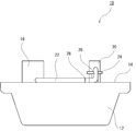
- FIG. 1 is a schematic diagram for explaining a configuration of a floating facility according to an embodiment
- FIG. 2 is a Gantt chart for explaining a device connection method in the floating facility of FIG.
- a floating facility 10 includes a hull 12, a premises electrical room (LER) 16 (first device in the present invention) and equipment installed on an upper deck 14 of the hull 12. 20 (a second device in the present invention), and a cable 22 for electrically connecting the LER 16 and the device 20.
- LER premises electrical room
- the “hull” means a main body of the floating facility 10 excluding the LER 16, the equipment 20, the cable 22, and other equipment.
- FPSO floating storage and loading facility
- FSO floating storage and loading facility
- FSU floating storage facility
- FLNG floating liquefied natural gas production facility
- the upper deck 14 is set as a construction reference plane.
- the upper side of the construction reference plane is referred to as “on board”, and the lower side of the construction reference plane is referred to as “inboard”.
- the LER 16 stores various electrical equipment such as a distribution board for supplying power to various devices installed in the floating facility 10, a watt hour meter for displaying the amount of power to be supplied, and a transformer for adjusting voltage. Equipment.
- the device 20 includes, for example, a power generation device such as a gas turbine for generating power, and an electric device such as a pump (motor).
- a power generation device such as a gas turbine for generating power
- an electric device such as a pump (motor).
- the device 20 is a power generation device
- power is transmitted from the device 20 to the LER 16 via the cable 22.
- the device 20 is an electric device
- power is transmitted from the LER 16 to the device 20 via the cable.
- the cable 22 is not particularly limited as long as it can electrically connect the LER 16 and the device 20 and can transmit power.
- the diameter of the cable 22 is preferably between 3 mm and 120 mm, more preferably between 10 mm and 80 mm.
- the LER 16 and the cable 22 and the device 20 and the cable 22 are directly connected, but may be connected via, for example, a sub-cable (not shown).
- the cable 22 and the sub-cable may be connected via a connector (not shown).
- the LER 16, the equipment 20, and the cable 22 are installed and laid on the upper deck 14 of the hull 12 according to the procedure shown in FIG.
- a first installation step of installing the LER 16 on the upper deck 14 is performed.
- a laying step of laying the cable 22 is performed.
- a second installation process of installing the device 20 on the upper deck 14 is performed.
- connection step of connecting the other end of the cable 22 and the device 20 is performed.
- the connection between one end of the cable 22 and the LER 16 may be performed at any timing in parallel with or after the laying step, but before the completion of the connecting step. It is preferably performed.
- FIG. 3 is a Gantt chart for explaining another device connection method in the floating facility of FIG.
- a first installation step of installing the LER 16 on the upper deck 14 is performed, and during the first installation step, a laying step of laying the cable 22 is performed. Then, after the completion of the first installation step, a second installation step of installing the device 20 on the upper deck 14 is performed.
- connection step of connecting the other end of the cable 22 and the device 20 is performed.
- the connection between the one end of the cable 22 and the LER 16 is performed in parallel with the laying step after completion of the first installation step or at any timing after that. Although it does not matter, it is preferable to be performed before the completion of the connection step.
- FIG. 4 is a Gantt chart for explaining another method of connecting equipment in the floating facility of FIG.
- the first installation step of installing the LER 16 on the upper deck 14 is performed, and the laying step of laying the cable 22 is completed before the completion of the first installation step.
- a process is performed.
- a second installation step of installing the device 20 on the upper deck 14 is performed.
- connection step of connecting the other end of the cable 22 and the device 20 is performed.
- the connection between one end of the cable 22 and the LER 16 may be performed at any timing as long as the connection is completed after the first installation step, but is performed before the completion of the connection step. Is preferred.
- FIG. 5 is a Gantt chart for explaining another method of connecting the equipment in the floating facility of FIG.
- a first installation step of installing the LER 16 on the upper deck 14 is performed.
- a second installation step of installing the device 20 on the upper deck 14 is performed, and a laying step of laying the cable 22 is completed before the completion of the second installation step.
- the laying process is performed.
- connection step of connecting the other end of the cable 22 and the device 20 is performed.
- the connection between the one end of the cable 22 and the LER 16 may be performed in parallel with the laying process or at any timing after that, but before the completion of the connecting process. It is preferably performed.
- FIG. 6 is a Gantt chart for explaining another method of connecting equipment in the floating facility of FIG.
- a first installation step of installing the LER 16 on the upper deck 14 is performed, and the laying step of laying the cable 22 is completed before the completion of the first installation step.
- a process is performed.
- a second installation step of installing the device 20 on the upper deck 14 is started.
- connection step of connecting the other end of the cable 22 and the device 20 is performed.
- the connection between one end of the cable 22 and the LER 16 may be performed at any timing as long as the connection is completed after the first installation step, but is performed before the completion of the connection step. Is preferred.
- FIG. 7 is a Gantt chart for explaining another method of connecting the equipment in the floating facility of FIG.
- a first installation step of installing the LER 16 on the upper deck 14 is performed, and a second installation step of installing the device 20 on the upper deck 14 is performed. Further, after the completion of the first installation step and before the completion of the second installation step, the laying step is performed so that the laying step of laying the cable 22 is completed.
- connection step of connecting the other end of the cable 22 and the device 20 is performed.
- the connection between the one end of the cable 22 and the LER 16 is performed in parallel with the laying step after completion of the first installation step or at any timing after that. Although it does not matter, it is preferable to be performed before the completion of the connection step.
- FIG. 8 is a Gantt chart for explaining another method of connecting the equipment in the floating facility of FIG.
- a first installation step of installing the LER 16 on the upper deck 14 is performed, and a second installation step of installing the device 20 on the upper deck 14 is performed.
- the laying step is performed so that the laying step of laying the cable 22 is completed before the first and second setting steps are completed.
- connection step of connecting the other end of the cable 22 and the device 20 is performed.
- the connection between one end of the cable 22 and the LER 16 may be performed at any timing as long as the connection is completed after the first installation step, but is performed before the completion of the connection step. Is preferred.
- FIG. 9 is a Gantt chart for explaining another method of connecting equipment in the floating facility of FIG.
- a first installation step of installing the LER 16 on the upper deck 14 is performed, and a second installation step of installing the device 20 on the upper deck 14 is performed.
- the laying step is performed so that the laying step of laying the cable 22 is completed simultaneously with the completion of the first installation step.
- the first installation step, the second installation step, and the laying step may be completed simultaneously.
- connection step of connecting the other end of the cable 22 and the device 20 is performed.
- the connection between one end of the cable 22 and the LER 16 may be performed at any timing as long as the connection is completed after the first installation step, but is performed before the completion of the connection step. Is preferred.
- the second installation step is completed after the completion of the first installation step, and the laying step is completed before the completion of the second installation step.
- each step is performed so as to be performed after the completion of the second installation step.
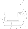
- FIG. 10 is a schematic diagram for explaining a configuration of a floating facility according to another embodiment.
- the floating facility 10 in the present embodiment has basically the same configuration as the floating facility 10 shown in FIG. 1, and the same components are denoted by the same reference numerals and detailed description thereof will be omitted. I do.
- the device 20 is placed on the rack 24 and is arranged at a high position away from the upper deck 14. That is, in the laying step, the cable 22 is laid below the device 20.
- the second installation step includes an arrangement step of arranging the sub-cable 26 having one end connected to the device 20 such that the other end of the sub-cable 26 is positioned on the upper deck 14, that is, the upper deck 14. Including.
- the sub-cable 26 is connected to the device 20.
- the sub-cable 26 is arranged so that the other end thereof is located on the upper deck 14.
- the device 20 and the cable 22 are connected by connecting the cable 22 and the other end of the sub-cable 26.
- the cable 22 and the sub-cable 26 can be connected via the connector 28.
- the connection work between the cable 22 and the sub-cable 26 is simplified, and a connection error or the like can be prevented.
- FIG. 11 is a schematic diagram for explaining a configuration of a floating facility according to another embodiment.
- the floating facility 10 in the present embodiment has basically the same configuration as the floating facility 10 shown in FIG. 1, and the same components are denoted by the same reference numerals and detailed description thereof will be omitted. I do.
- the device 20 is modularized as the module 18 in advance together with peripheral devices.
- the second installation step is a step in which the sub cable 26 having one end connected to the device 20 is connected to the sub cable 26 from the module 18 such that the other end of the sub cable 26 is positioned on the laying height of the cable 22, that is, the upper deck 14. 26 is included.
- the sub-cable 26 is connected to the device 20.
- the sub-cable 26 is arranged so that the other end thereof is located on the upper deck 14.
- the device 20 and the cable 22 are connected by connecting the cable 22 and the other end of the sub-cable 26.
- the cable 22 and the sub-cable 26 can be connected via the connector 28.
- the connection work between the cable 22 and the sub-cable 26 is simplified, and a connection error or the like can be prevented.
- FIG. 12 is a schematic diagram for explaining a configuration of a floating facility according to another embodiment.
- the floating facility 10 in the present embodiment has basically the same configuration as the floating facility 10 shown in FIG. 1, and the same components are denoted by the same reference numerals and detailed description thereof will be omitted. I do.
- the LER 16 and the cable 22 are arranged inside the ship.
- the device 20 is modularized as a module 18 in advance together with peripheral devices.
- a vertical installation step may be performed in the second installation step, and the device 20 and the cable 22 may be connected via the sub-cable 26.
- the LER 16 and the cable 22 are arranged on the ship.
- the LER 16 is arranged on the ship, conversely, the device 20 is arranged on the ship, and only the cable 22 is arranged on the ship. It is also possible. Further, the LER 16, the cable 22, and the equipment 22 can be arranged in the ship.
- the present invention is not limited to this.
- the present invention is not limited to this.
- the cable 22 in the laying process, is moved so as to crawl on the top of the pipe rack, the inside of the pipe rack, and the top of the module 18 and the module 18. May be laid.
- the end of the cable 22 is located on the pipe rack, and the other end of the sub-cable connected to the device 20 is located on the pipe rack for connection to the end of the cable 22. It will be.
- the LER 16 is described as the first device and the device 20 is described as the second device.
- the LER 16 may be the second device and the device 20 may be the first device.
- the first device and the second device may both be devices installed in the module, and may not include the LER 16.
- the present invention can be applied to a land plant such as a land natural gas liquefaction plant (LNG plant) as a plant.
- LNG plant land natural gas liquefaction plant
- the LER and various devices are generally installed at the time of outfitting work performed at sea. For example, when the LER is installed inside a ship, the outfitting work is performed.
- the outfitting work is performed.
- Various changes can be made without departing from the purpose of the present invention, such as performing before.
Landscapes
- Engineering & Computer Science (AREA)
- Architecture (AREA)
- Structural Engineering (AREA)
- Civil Engineering (AREA)
- Chemical & Material Sciences (AREA)
- Combustion & Propulsion (AREA)
- Mechanical Engineering (AREA)
- Ocean & Marine Engineering (AREA)
- Details Of Indoor Wiring (AREA)
Abstract
Description
浮体式設備の艤装工事では、居住部などの内装のほか、配電設備が格納された電気室、計器類が格納された計器室、発電のためのガスタービンなどの各種機器が設置される。
第1の機器を設置する第1設置工程と、
第2の機器を設置する第2設置工程と、
前記ケーブルを敷設する敷設工程と、
前記ケーブルと前記第2の機器とを接続する接続工程と
を含み、
前記第2設置工程は、前記第1設置工程の完了以降に完了し、
前記敷設工程は、前記第2設置工程の完了以前に完了し、
前記接続工程は、前記第2設置工程の完了以降に実施される、プラント用機器接続方法。
前記接続工程において、
前記第2の機器と前記ケーブルとが前記サブケーブルを介して接続される、[1]に記載のプラント用機器接続方法。
前記第2の機器は、プラントの建設用のモジュール内に組み込まれた状態で設置される、[1]~[5]の何れか一項に記載のプラント用機器接続方法。
前記第2設置工程は、前記第2の機器に一端が接続されたサブケーブルを、前記ケーブルの敷設高さに該サブケーブルの他端が位置するように前記モジュールから垂設する垂設工程を含み、
前記接続工程は、前記ケーブルと前記サブケーブルとがコネクタを介して接続される、[6]に記載のプラント用機器接続方法。
なお、本実施形態においては、ケーブル22の一端とLER16との接続は、敷設工程と並行して、もしくは、それ以降であれば、どのタイミングで行っても構わないが、接続工程の完了以前に実施されることが好ましい。
図3は、図1の浮体式設備における他の機器接続方法を説明するためのガントチャートである。
なお、本実施形態においては、ケーブル22の一端とLER16との接続は、第1設置工程の完了後であれば、敷設工程と並行して、もしくは、それ以降であれば、どのタイミングで行っても構わないが、接続工程の完了以前に実施されることが好ましい。
なお、本実施形態においては、ケーブル22の一端とLER16との接続は、第1設置工程の完了後であれば、どのタイミングで行っても構わないが、接続工程の完了以前に実施されることが好ましい。
なお、本実施形態においては、ケーブル22の一端とLER16との接続は、敷設工程と並行して、もしくは、それ以降であれば、どのタイミングで行っても構わないが、接続工程の完了以前に実施されることが好ましい。
なお、本実施形態においては、ケーブル22の一端とLER16との接続は、第1設置工程の完了後であれば、どのタイミングで行っても構わないが、接続工程の完了以前に実施されることが好ましい。
なお、本実施形態においては、ケーブル22の一端とLER16との接続は、第1設置工程の完了後であれば、敷設工程と並行して、もしくは、それ以降であれば、どのタイミングで行っても構わないが、接続工程の完了以前に実施されることが好ましい。
なお、本実施形態においては、ケーブル22の一端とLER16との接続は、第1設置工程の完了後であれば、どのタイミングで行っても構わないが、接続工程の完了以前に実施されることが好ましい。
なお、本実施形態においては、ケーブル22の一端とLER16との接続は、第1設置工程の完了後であれば、どのタイミングで行っても構わないが、接続工程の完了以前に実施されることが好ましい。
本実施形態における浮体式設備10は、基本的には、図1に示す浮体式設備10と同様な構成であり、同様な構成要素には、同じ符号を付して、その詳細な説明を省略する。
このように、ケーブル22とサブケーブル26とを接続する場合には、コネクタ28を介して接続することもできる。このように構成することで、ケーブル22とサブケーブル26との接続作業が簡易化され、また、接続ミスなどを防止することができる。
本実施形態における浮体式設備10は、基本的には、図1に示す浮体式設備10と同様な構成であり、同様な構成要素には、同じ符号を付して、その詳細な説明を省略する。
このように、ケーブル22とサブケーブル26とを接続する場合には、コネクタ28を介して接続することもできる。このように構成することで、ケーブル22とサブケーブル26との接続作業が簡易化され、また、接続ミスなどを防止することができる。
本実施形態における浮体式設備10は、基本的には、図1に示す浮体式設備10と同様な構成であり、同様な構成要素には、同じ符号を付して、その詳細な説明を省略する。
12 船体
14 上甲板
18 モジュール
20 機器
22 ケーブル
24 ラック
26 サブケーブル
28 コネクタ
Claims (8)
- プラントの建設において、複数の機器をケーブルにより接続するプラント用機器接続方法であって、
第1の機器を設置する第1設置工程と、
第2の機器を設置する第2設置工程と、
前記ケーブルを敷設する敷設工程と、
前記ケーブルと前記第2の機器とを接続する接続工程と
を含み、
前記第2設置工程は、前記第1設置工程の完了以降に完了し、
前記敷設工程は、前記第2設置工程の完了以前に完了し、
前記接続工程は、前記第2設置工程の完了以降に実施される、プラント用機器接続方法。 - 前記第2設置工程は、前記第2の機器に一端が接続されたサブケーブルを、前記ケーブルの敷設高さに該サブケーブルの他端が位置するように配置する配置工程を含み、
前記接続工程において、
前記第2の機器と前記ケーブルとが前記サブケーブルを介して接続される、請求項1記載のプラント用機器接続方法。 - 前記ケーブルと前記サブケーブルとがコネクタを介して接続される、請求項2記載のプラント用機器接続方法。
- 前記第1の機器および前記第2の機器の少なくとも一方は、高さ方向において前記プラントの建設基準面から離間した位置に配置される、請求項1~3の何れか一項に記載のプラント用機器接続方法。
- 前記ケーブルは、前記プラントの建設基準面下に敷設される、請求項1~4の何れか一項に記載のプラント用機器接続方法。
- 前記第1の機器は、構内電気室(Local Electrical Room)であり、
前記第2の機器は、プラントの建設用のモジュール内に組み込まれた状態で設置される、請求項1~5の何れか一項に記載のプラント用機器接続方法。 - 前記敷設工程では、前記ケーブルは、前記第2の機器よりも下方に敷設され、
前記第2設置工程は、前記第2の機器に一端が接続されたサブケーブルを、前記ケーブルの敷設高さに該サブケーブルの他端が位置するように前記モジュールから垂設する垂設工程を含み、
前記接続工程は、前記ケーブルと前記サブケーブルとがコネクタを介して接続される、請求項6に記載のプラント用機器接続方法。 - 前記プラントが浮体式設備であり、前記敷設工程、第2設置工程、および前記接続工程が洋上で行われる、請求項1~7の何れか一項に記載のプラント用機器接続方法。
Priority Applications (4)
| Application Number | Priority Date | Filing Date | Title |
|---|---|---|---|
| KR1020207035930A KR102625551B1 (ko) | 2018-06-19 | 2018-06-19 | 플랜트용 기기 접속 방법 |
| CN201880093859.8A CN112203933B (zh) | 2018-06-19 | 2018-06-19 | 工厂用机器连接方法 |
| PCT/JP2018/023318 WO2019244249A1 (ja) | 2018-06-19 | 2018-06-19 | プラント用機器接続方法 |
| SG11202012251SA SG11202012251SA (en) | 2018-06-19 | 2018-06-19 | Device connection method for plant |
Applications Claiming Priority (1)
| Application Number | Priority Date | Filing Date | Title |
|---|---|---|---|
| PCT/JP2018/023318 WO2019244249A1 (ja) | 2018-06-19 | 2018-06-19 | プラント用機器接続方法 |
Publications (1)
| Publication Number | Publication Date |
|---|---|
| WO2019244249A1 true WO2019244249A1 (ja) | 2019-12-26 |
Family
ID=68983864
Family Applications (1)
| Application Number | Title | Priority Date | Filing Date |
|---|---|---|---|
| PCT/JP2018/023318 Ceased WO2019244249A1 (ja) | 2018-06-19 | 2018-06-19 | プラント用機器接続方法 |
Country Status (4)
| Country | Link |
|---|---|
| KR (1) | KR102625551B1 (ja) |
| CN (1) | CN112203933B (ja) |
| SG (1) | SG11202012251SA (ja) |
| WO (1) | WO2019244249A1 (ja) |
Citations (1)
| Publication number | Priority date | Publication date | Assignee | Title |
|---|---|---|---|---|
| JPS5819112A (ja) * | 1981-07-27 | 1983-02-04 | 株式会社フジクラ | ケ−ブルのブロック配線工法及びケ−ブルブロック |
Family Cites Families (16)
| Publication number | Priority date | Publication date | Assignee | Title |
|---|---|---|---|---|
| DE19860211C1 (de) * | 1998-12-24 | 2000-11-23 | Aerodyn Energiesysteme Gmbh | Verfahren zum Verlegen von elektrischen Kabeln von einer ersten Offshore-Windenergieanlage zu einer zweiten Offshore-Windenergieanlage |
| JP2002135933A (ja) * | 2000-10-18 | 2002-05-10 | Kansai Electric Power Co Inc:The | 光ケーブルの敷設方法並びにその装置 |
| JP3479888B2 (ja) * | 2001-04-18 | 2003-12-15 | 日本電気株式会社 | ケーブル敷設工法とその補助装置 |
| JP2004112853A (ja) * | 2002-09-13 | 2004-04-08 | Mitsubishi Heavy Ind Ltd | ケーブル敷設工事管理システム |
| JP4436203B2 (ja) * | 2004-07-20 | 2010-03-24 | 株式会社アイ・エイチ・アイ マリンユナイテッド | 船舶 |
| JP4514679B2 (ja) * | 2005-09-08 | 2010-07-28 | 中国電力株式会社 | 発電所建屋のケーブル室布設構造 |
| KR20090067298A (ko) * | 2007-12-21 | 2009-06-25 | 현대중공업 주식회사 | 선박의 가압펌프 구동용 컨트롤러 |
| CA2806161C (en) * | 2010-08-20 | 2015-06-02 | Ehtp Entreprise Hydraulique Et Travaux Publics | Method for laying a plurality of successive sections of cables in order to form a cabled connection of great length |
| AU2011318237A1 (en) * | 2010-10-20 | 2013-05-23 | Leigh Klug | Cable laying device and cable installation system |
| ITFI20120114A1 (it) | 2012-06-08 | 2013-12-09 | Nuovo Pignone Srl | "modular gas turbine plant with a heavy duty gas turbine" |
| CN104517550A (zh) * | 2013-09-30 | 2015-04-15 | 中铁六局集团有限公司 | 一种地铁乘客信息系统施工工法 |
| KR20160032572A (ko) * | 2014-09-16 | 2016-03-24 | 대우조선해양 주식회사 | 선박 거주구 전원 공급 장치 및 방법 |
| CN104917109A (zh) * | 2015-06-09 | 2015-09-16 | 上海船厂船舶有限公司 | 船舶上层建筑至机舱的主干电缆逆向敷设方法 |
| CN204886013U (zh) * | 2015-08-25 | 2015-12-16 | 启东丰顺船舶重工有限公司 | 一种罐体式lng船电缆布置结构 |
| CN106129906B (zh) * | 2016-06-30 | 2019-01-11 | 中国一冶集团有限公司 | 一种工业工程电缆工序信息处理方法 |
| CN107317266A (zh) * | 2017-08-10 | 2017-11-03 | 嘉兴恒创电力设计研究院有限公司 | 应用于智能变电站的光缆及电缆敷设方法 |
-
2018
- 2018-06-19 SG SG11202012251SA patent/SG11202012251SA/en unknown
- 2018-06-19 CN CN201880093859.8A patent/CN112203933B/zh active Active
- 2018-06-19 WO PCT/JP2018/023318 patent/WO2019244249A1/ja not_active Ceased
- 2018-06-19 KR KR1020207035930A patent/KR102625551B1/ko active Active
Patent Citations (1)
| Publication number | Priority date | Publication date | Assignee | Title |
|---|---|---|---|---|
| JPS5819112A (ja) * | 1981-07-27 | 1983-02-04 | 株式会社フジクラ | ケ−ブルのブロック配線工法及びケ−ブルブロック |
Non-Patent Citations (3)
| Title |
|---|
| "Examples of ship electrical installation construction illustrated with pictures", THE SHIP'S ELECTRIC INSTALLATION CONTRACTORS' ASSOCIATION OF JAPAN, 22 August 2018 (2018-08-22), Retrieved from the Internet <URL:http://denso.sokei.co.jp/photo/gisokoji_yoryo_photo_100.pdf> * |
| "Ship electrical equipment construction handbook: construction part", THE SHIP'S ELECTRIC INSTALLATION CONSTRUCTION' ASSOCIATION, 1996 * |
| AHMAD , NORHAZIYAH AFIQAH BINTI ET AL.: "Fabrication Scheduling of Electrical House of FPSO using Dependency Structure Matrix", JOURNAL OF OCEAN, MECHANICAL AND AEROSPACE - SCIENCE AND ENGINEERING, vol. 8, 20 June 2014 (2014-06-20), pages 17 - 25, ISSN: 2527-6085 * |
Also Published As
| Publication number | Publication date |
|---|---|
| KR102625551B1 (ko) | 2024-01-16 |
| CN112203933A (zh) | 2021-01-08 |
| CN112203933B (zh) | 2023-07-25 |
| KR20210021470A (ko) | 2021-02-26 |
| SG11202012251SA (en) | 2021-01-28 |
Similar Documents
| Publication | Publication Date | Title |
|---|---|---|
| EP2951083B1 (en) | Lng carrier construction method | |
| US20210339989A1 (en) | Method and apparatus for a mdoiular jack up rig assembley | |
| US20050206239A1 (en) | Floating power generation system | |
| KR200437039Y1 (ko) | 안전 지대에 주 발전기를 구비한 부유식 생산 저장 선박 | |
| WO2017038524A1 (ja) | 浮体式洋上設備、及び浮体式洋上設備の電力供給方法 | |
| US8087369B2 (en) | Modular ship and floatable modules intended to be part of the ship | |
| MX2020011920A (es) | Equipos, metodos y sistemas de licuefaccion. | |
| KR101742289B1 (ko) | 해상 부유물 및 그러한 해상 부유물의 개조 방법 | |
| CA2872466A1 (en) | System and method to control electrical power input to direct electric heat pipeline | |
| DK180544B1 (en) | Subsea Hydrocarbon Production System | |
| WO2019244249A1 (ja) | プラント用機器接続方法 | |
| EP3131807B1 (en) | Method of integrating new built structural block and sponson with existing lng carrier | |
| GB2547419A (en) | Vehicle dynamic position powering system and method | |
| JP2022044969A (ja) | 液化ガスの移載方法、ボイルオフガスの移載方法 | |
| KR20160001236U (ko) | 걸이 형 모노레일 직렬 연결장치 및 이를 구비하는 해양구조물 | |
| KR20130050067A (ko) | Lng-fpso 가스 시운전을 위한 계류장치를 구비한 해상 부유 구조물 | |
| KR102130715B1 (ko) | 선박의 연안 가스 테스트 방법 | |
| KR20170019784A (ko) | 모듈의 전력제어시스템 및 모듈의 테스트 방법 | |
| KR102170040B1 (ko) | 액화가스 부유식 생산저장하역설비 | |
| KR102744395B1 (ko) | 부유식 구조물의 전력 생산 시스템 | |
| KR20160031747A (ko) | Lng 운반선을 이용한 lng fpso 및 그 개조방법 | |
| JP7648832B1 (ja) | 船舶用荷役システム | |
| KR102450841B1 (ko) | 액화천연가스 벙커링 선박의 벙커링 전력 공급 시스템 | |
| KR20120052482A (ko) | 선박형 해양 구조물 케이블 트레이 | |
| Brown | FPSO: Lessons Learned: An Exploration of Floating, Production, Storage, and Offloading Electrical Systems and Installation Issues |
Legal Events
| Date | Code | Title | Description |
|---|---|---|---|
| 121 | Ep: the epo has been informed by wipo that ep was designated in this application |
Ref document number: 18923376 Country of ref document: EP Kind code of ref document: A1 |
|
| ENP | Entry into the national phase |
Ref document number: 20207035930 Country of ref document: KR Kind code of ref document: A |
|
| NENP | Non-entry into the national phase |
Ref country code: DE |
|
| 122 | Ep: pct application non-entry in european phase |
Ref document number: 18923376 Country of ref document: EP Kind code of ref document: A1 |
|
| NENP | Non-entry into the national phase |
Ref country code: JP |