WO2019240023A1 - エアシリンダの流体回路 - Google Patents
エアシリンダの流体回路 Download PDFInfo
- Publication number
- WO2019240023A1 WO2019240023A1 PCT/JP2019/022678 JP2019022678W WO2019240023A1 WO 2019240023 A1 WO2019240023 A1 WO 2019240023A1 JP 2019022678 W JP2019022678 W JP 2019022678W WO 2019240023 A1 WO2019240023 A1 WO 2019240023A1
- Authority
- WO
- WIPO (PCT)
- Prior art keywords
- air
- flow path
- air chamber
- valve
- fluid circuit
- Prior art date
Links
Images


Classifications
-
- F—MECHANICAL ENGINEERING; LIGHTING; HEATING; WEAPONS; BLASTING
- F15—FLUID-PRESSURE ACTUATORS; HYDRAULICS OR PNEUMATICS IN GENERAL
- F15B—SYSTEMS ACTING BY MEANS OF FLUIDS IN GENERAL; FLUID-PRESSURE ACTUATORS, e.g. SERVOMOTORS; DETAILS OF FLUID-PRESSURE SYSTEMS, NOT OTHERWISE PROVIDED FOR
- F15B11/00—Servomotor systems without provision for follow-up action; Circuits therefor
- F15B11/02—Systems essentially incorporating special features for controlling the speed or actuating force of an output member
- F15B11/04—Systems essentially incorporating special features for controlling the speed or actuating force of an output member for controlling the speed
- F15B11/042—Systems essentially incorporating special features for controlling the speed or actuating force of an output member for controlling the speed by means in the feed line, i.e. "meter in"
-
- F—MECHANICAL ENGINEERING; LIGHTING; HEATING; WEAPONS; BLASTING
- F15—FLUID-PRESSURE ACTUATORS; HYDRAULICS OR PNEUMATICS IN GENERAL
- F15B—SYSTEMS ACTING BY MEANS OF FLUIDS IN GENERAL; FLUID-PRESSURE ACTUATORS, e.g. SERVOMOTORS; DETAILS OF FLUID-PRESSURE SYSTEMS, NOT OTHERWISE PROVIDED FOR
- F15B11/00—Servomotor systems without provision for follow-up action; Circuits therefor
- F15B11/06—Servomotor systems without provision for follow-up action; Circuits therefor involving features specific to the use of a compressible medium, e.g. air, steam
-
- F—MECHANICAL ENGINEERING; LIGHTING; HEATING; WEAPONS; BLASTING
- F15—FLUID-PRESSURE ACTUATORS; HYDRAULICS OR PNEUMATICS IN GENERAL
- F15B—SYSTEMS ACTING BY MEANS OF FLUIDS IN GENERAL; FLUID-PRESSURE ACTUATORS, e.g. SERVOMOTORS; DETAILS OF FLUID-PRESSURE SYSTEMS, NOT OTHERWISE PROVIDED FOR
- F15B1/00—Installations or systems with accumulators; Supply reservoir or sump assemblies
- F15B1/26—Supply reservoir or sump assemblies
-
- F—MECHANICAL ENGINEERING; LIGHTING; HEATING; WEAPONS; BLASTING
- F15—FLUID-PRESSURE ACTUATORS; HYDRAULICS OR PNEUMATICS IN GENERAL
- F15B—SYSTEMS ACTING BY MEANS OF FLUIDS IN GENERAL; FLUID-PRESSURE ACTUATORS, e.g. SERVOMOTORS; DETAILS OF FLUID-PRESSURE SYSTEMS, NOT OTHERWISE PROVIDED FOR
- F15B11/00—Servomotor systems without provision for follow-up action; Circuits therefor
- F15B11/02—Systems essentially incorporating special features for controlling the speed or actuating force of an output member
- F15B11/024—Systems essentially incorporating special features for controlling the speed or actuating force of an output member by means of differential connection of the servomotor lines, e.g. regenerative circuits
-
- F—MECHANICAL ENGINEERING; LIGHTING; HEATING; WEAPONS; BLASTING
- F15—FLUID-PRESSURE ACTUATORS; HYDRAULICS OR PNEUMATICS IN GENERAL
- F15B—SYSTEMS ACTING BY MEANS OF FLUIDS IN GENERAL; FLUID-PRESSURE ACTUATORS, e.g. SERVOMOTORS; DETAILS OF FLUID-PRESSURE SYSTEMS, NOT OTHERWISE PROVIDED FOR
- F15B11/00—Servomotor systems without provision for follow-up action; Circuits therefor
- F15B11/02—Systems essentially incorporating special features for controlling the speed or actuating force of an output member
- F15B11/04—Systems essentially incorporating special features for controlling the speed or actuating force of an output member for controlling the speed
- F15B11/0413—Systems essentially incorporating special features for controlling the speed or actuating force of an output member for controlling the speed in one direction only, with no control in the reverse direction, e.g. check valve in parallel with a throttle valve
-
- F—MECHANICAL ENGINEERING; LIGHTING; HEATING; WEAPONS; BLASTING
- F15—FLUID-PRESSURE ACTUATORS; HYDRAULICS OR PNEUMATICS IN GENERAL
- F15B—SYSTEMS ACTING BY MEANS OF FLUIDS IN GENERAL; FLUID-PRESSURE ACTUATORS, e.g. SERVOMOTORS; DETAILS OF FLUID-PRESSURE SYSTEMS, NOT OTHERWISE PROVIDED FOR
- F15B11/00—Servomotor systems without provision for follow-up action; Circuits therefor
- F15B11/02—Systems essentially incorporating special features for controlling the speed or actuating force of an output member
- F15B11/04—Systems essentially incorporating special features for controlling the speed or actuating force of an output member for controlling the speed
- F15B11/044—Systems essentially incorporating special features for controlling the speed or actuating force of an output member for controlling the speed by means in the return line, i.e. "meter out"
-
- F—MECHANICAL ENGINEERING; LIGHTING; HEATING; WEAPONS; BLASTING
- F15—FLUID-PRESSURE ACTUATORS; HYDRAULICS OR PNEUMATICS IN GENERAL
- F15B—SYSTEMS ACTING BY MEANS OF FLUIDS IN GENERAL; FLUID-PRESSURE ACTUATORS, e.g. SERVOMOTORS; DETAILS OF FLUID-PRESSURE SYSTEMS, NOT OTHERWISE PROVIDED FOR
- F15B11/00—Servomotor systems without provision for follow-up action; Circuits therefor
- F15B11/06—Servomotor systems without provision for follow-up action; Circuits therefor involving features specific to the use of a compressible medium, e.g. air, steam
- F15B11/064—Servomotor systems without provision for follow-up action; Circuits therefor involving features specific to the use of a compressible medium, e.g. air, steam with devices for saving the compressible medium
-
- F—MECHANICAL ENGINEERING; LIGHTING; HEATING; WEAPONS; BLASTING
- F15—FLUID-PRESSURE ACTUATORS; HYDRAULICS OR PNEUMATICS IN GENERAL
- F15B—SYSTEMS ACTING BY MEANS OF FLUIDS IN GENERAL; FLUID-PRESSURE ACTUATORS, e.g. SERVOMOTORS; DETAILS OF FLUID-PRESSURE SYSTEMS, NOT OTHERWISE PROVIDED FOR
- F15B13/00—Details of servomotor systems ; Valves for servomotor systems
- F15B13/02—Fluid distribution or supply devices characterised by their adaptation to the control of servomotors
- F15B13/022—Flow-dividers; Priority valves
-
- F—MECHANICAL ENGINEERING; LIGHTING; HEATING; WEAPONS; BLASTING
- F15—FLUID-PRESSURE ACTUATORS; HYDRAULICS OR PNEUMATICS IN GENERAL
- F15B—SYSTEMS ACTING BY MEANS OF FLUIDS IN GENERAL; FLUID-PRESSURE ACTUATORS, e.g. SERVOMOTORS; DETAILS OF FLUID-PRESSURE SYSTEMS, NOT OTHERWISE PROVIDED FOR
- F15B13/00—Details of servomotor systems ; Valves for servomotor systems
- F15B13/02—Fluid distribution or supply devices characterised by their adaptation to the control of servomotors
- F15B13/027—Check valves
-
- F—MECHANICAL ENGINEERING; LIGHTING; HEATING; WEAPONS; BLASTING
- F15—FLUID-PRESSURE ACTUATORS; HYDRAULICS OR PNEUMATICS IN GENERAL
- F15B—SYSTEMS ACTING BY MEANS OF FLUIDS IN GENERAL; FLUID-PRESSURE ACTUATORS, e.g. SERVOMOTORS; DETAILS OF FLUID-PRESSURE SYSTEMS, NOT OTHERWISE PROVIDED FOR
- F15B11/00—Servomotor systems without provision for follow-up action; Circuits therefor
- F15B11/02—Systems essentially incorporating special features for controlling the speed or actuating force of an output member
- F15B11/024—Systems essentially incorporating special features for controlling the speed or actuating force of an output member by means of differential connection of the servomotor lines, e.g. regenerative circuits
- F15B2011/0246—Systems essentially incorporating special features for controlling the speed or actuating force of an output member by means of differential connection of the servomotor lines, e.g. regenerative circuits with variable regeneration flow
-
- F—MECHANICAL ENGINEERING; LIGHTING; HEATING; WEAPONS; BLASTING
- F15—FLUID-PRESSURE ACTUATORS; HYDRAULICS OR PNEUMATICS IN GENERAL
- F15B—SYSTEMS ACTING BY MEANS OF FLUIDS IN GENERAL; FLUID-PRESSURE ACTUATORS, e.g. SERVOMOTORS; DETAILS OF FLUID-PRESSURE SYSTEMS, NOT OTHERWISE PROVIDED FOR
- F15B2211/00—Circuits for servomotor systems
- F15B2211/30—Directional control
- F15B2211/305—Directional control characterised by the type of valves
- F15B2211/30505—Non-return valves, i.e. check valves
-
- F—MECHANICAL ENGINEERING; LIGHTING; HEATING; WEAPONS; BLASTING
- F15—FLUID-PRESSURE ACTUATORS; HYDRAULICS OR PNEUMATICS IN GENERAL
- F15B—SYSTEMS ACTING BY MEANS OF FLUIDS IN GENERAL; FLUID-PRESSURE ACTUATORS, e.g. SERVOMOTORS; DETAILS OF FLUID-PRESSURE SYSTEMS, NOT OTHERWISE PROVIDED FOR
- F15B2211/00—Circuits for servomotor systems
- F15B2211/30—Directional control
- F15B2211/305—Directional control characterised by the type of valves
- F15B2211/30525—Directional control valves, e.g. 4/3-directional control valve
-
- F—MECHANICAL ENGINEERING; LIGHTING; HEATING; WEAPONS; BLASTING
- F15—FLUID-PRESSURE ACTUATORS; HYDRAULICS OR PNEUMATICS IN GENERAL
- F15B—SYSTEMS ACTING BY MEANS OF FLUIDS IN GENERAL; FLUID-PRESSURE ACTUATORS, e.g. SERVOMOTORS; DETAILS OF FLUID-PRESSURE SYSTEMS, NOT OTHERWISE PROVIDED FOR
- F15B2211/00—Circuits for servomotor systems
- F15B2211/30—Directional control
- F15B2211/305—Directional control characterised by the type of valves
- F15B2211/3056—Assemblies of multiple valves
- F15B2211/30565—Assemblies of multiple valves having multiple valves for a single output member, e.g. for creating higher valve function by use of multiple valves like two 2/2-valves replacing a 5/3-valve
- F15B2211/3058—Assemblies of multiple valves having multiple valves for a single output member, e.g. for creating higher valve function by use of multiple valves like two 2/2-valves replacing a 5/3-valve having additional valves for interconnecting the fluid chambers of a double-acting actuator, e.g. for regeneration mode or for floating mode
-
- F—MECHANICAL ENGINEERING; LIGHTING; HEATING; WEAPONS; BLASTING
- F15—FLUID-PRESSURE ACTUATORS; HYDRAULICS OR PNEUMATICS IN GENERAL
- F15B—SYSTEMS ACTING BY MEANS OF FLUIDS IN GENERAL; FLUID-PRESSURE ACTUATORS, e.g. SERVOMOTORS; DETAILS OF FLUID-PRESSURE SYSTEMS, NOT OTHERWISE PROVIDED FOR
- F15B2211/00—Circuits for servomotor systems
- F15B2211/30—Directional control
- F15B2211/31—Directional control characterised by the positions of the valve element
- F15B2211/3122—Special positions other than the pump port being connected to working ports or the working ports being connected to the return line
- F15B2211/3133—Regenerative position connecting the working ports or connecting the working ports to the pump, e.g. for high-speed approach stroke
-
- F—MECHANICAL ENGINEERING; LIGHTING; HEATING; WEAPONS; BLASTING
- F15—FLUID-PRESSURE ACTUATORS; HYDRAULICS OR PNEUMATICS IN GENERAL
- F15B—SYSTEMS ACTING BY MEANS OF FLUIDS IN GENERAL; FLUID-PRESSURE ACTUATORS, e.g. SERVOMOTORS; DETAILS OF FLUID-PRESSURE SYSTEMS, NOT OTHERWISE PROVIDED FOR
- F15B2211/00—Circuits for servomotor systems
- F15B2211/40—Flow control
- F15B2211/405—Flow control characterised by the type of flow control means or valve
- F15B2211/40507—Flow control characterised by the type of flow control means or valve with constant throttles or orifices
-
- F—MECHANICAL ENGINEERING; LIGHTING; HEATING; WEAPONS; BLASTING
- F15—FLUID-PRESSURE ACTUATORS; HYDRAULICS OR PNEUMATICS IN GENERAL
- F15B—SYSTEMS ACTING BY MEANS OF FLUIDS IN GENERAL; FLUID-PRESSURE ACTUATORS, e.g. SERVOMOTORS; DETAILS OF FLUID-PRESSURE SYSTEMS, NOT OTHERWISE PROVIDED FOR
- F15B2211/00—Circuits for servomotor systems
- F15B2211/40—Flow control
- F15B2211/405—Flow control characterised by the type of flow control means or valve
- F15B2211/40515—Flow control characterised by the type of flow control means or valve with variable throttles or orifices
-
- F—MECHANICAL ENGINEERING; LIGHTING; HEATING; WEAPONS; BLASTING
- F15—FLUID-PRESSURE ACTUATORS; HYDRAULICS OR PNEUMATICS IN GENERAL
- F15B—SYSTEMS ACTING BY MEANS OF FLUIDS IN GENERAL; FLUID-PRESSURE ACTUATORS, e.g. SERVOMOTORS; DETAILS OF FLUID-PRESSURE SYSTEMS, NOT OTHERWISE PROVIDED FOR
- F15B2211/00—Circuits for servomotor systems
- F15B2211/40—Flow control
- F15B2211/405—Flow control characterised by the type of flow control means or valve
- F15B2211/40576—Assemblies of multiple valves
- F15B2211/40584—Assemblies of multiple valves the flow control means arranged in parallel with a check valve
-
- F—MECHANICAL ENGINEERING; LIGHTING; HEATING; WEAPONS; BLASTING
- F15—FLUID-PRESSURE ACTUATORS; HYDRAULICS OR PNEUMATICS IN GENERAL
- F15B—SYSTEMS ACTING BY MEANS OF FLUIDS IN GENERAL; FLUID-PRESSURE ACTUATORS, e.g. SERVOMOTORS; DETAILS OF FLUID-PRESSURE SYSTEMS, NOT OTHERWISE PROVIDED FOR
- F15B2211/00—Circuits for servomotor systems
- F15B2211/40—Flow control
- F15B2211/415—Flow control characterised by the connections of the flow control means in the circuit
- F15B2211/41527—Flow control characterised by the connections of the flow control means in the circuit being connected to an output member and a directional control valve
-
- F—MECHANICAL ENGINEERING; LIGHTING; HEATING; WEAPONS; BLASTING
- F15—FLUID-PRESSURE ACTUATORS; HYDRAULICS OR PNEUMATICS IN GENERAL
- F15B—SYSTEMS ACTING BY MEANS OF FLUIDS IN GENERAL; FLUID-PRESSURE ACTUATORS, e.g. SERVOMOTORS; DETAILS OF FLUID-PRESSURE SYSTEMS, NOT OTHERWISE PROVIDED FOR
- F15B2211/00—Circuits for servomotor systems
- F15B2211/40—Flow control
- F15B2211/455—Control of flow in the feed line, i.e. meter-in control
-
- F—MECHANICAL ENGINEERING; LIGHTING; HEATING; WEAPONS; BLASTING
- F15—FLUID-PRESSURE ACTUATORS; HYDRAULICS OR PNEUMATICS IN GENERAL
- F15B—SYSTEMS ACTING BY MEANS OF FLUIDS IN GENERAL; FLUID-PRESSURE ACTUATORS, e.g. SERVOMOTORS; DETAILS OF FLUID-PRESSURE SYSTEMS, NOT OTHERWISE PROVIDED FOR
- F15B2211/00—Circuits for servomotor systems
- F15B2211/40—Flow control
- F15B2211/46—Control of flow in the return line, i.e. meter-out control
-
- F—MECHANICAL ENGINEERING; LIGHTING; HEATING; WEAPONS; BLASTING
- F15—FLUID-PRESSURE ACTUATORS; HYDRAULICS OR PNEUMATICS IN GENERAL
- F15B—SYSTEMS ACTING BY MEANS OF FLUIDS IN GENERAL; FLUID-PRESSURE ACTUATORS, e.g. SERVOMOTORS; DETAILS OF FLUID-PRESSURE SYSTEMS, NOT OTHERWISE PROVIDED FOR
- F15B2211/00—Circuits for servomotor systems
- F15B2211/70—Output members, e.g. hydraulic motors or cylinders or control therefor
- F15B2211/705—Output members, e.g. hydraulic motors or cylinders or control therefor characterised by the type of output members or actuators
- F15B2211/7051—Linear output members
- F15B2211/7053—Double-acting output members
-
- F—MECHANICAL ENGINEERING; LIGHTING; HEATING; WEAPONS; BLASTING
- F15—FLUID-PRESSURE ACTUATORS; HYDRAULICS OR PNEUMATICS IN GENERAL
- F15B—SYSTEMS ACTING BY MEANS OF FLUIDS IN GENERAL; FLUID-PRESSURE ACTUATORS, e.g. SERVOMOTORS; DETAILS OF FLUID-PRESSURE SYSTEMS, NOT OTHERWISE PROVIDED FOR
- F15B2211/00—Circuits for servomotor systems
- F15B2211/70—Output members, e.g. hydraulic motors or cylinders or control therefor
- F15B2211/75—Control of speed of the output member
-
- F—MECHANICAL ENGINEERING; LIGHTING; HEATING; WEAPONS; BLASTING
- F15—FLUID-PRESSURE ACTUATORS; HYDRAULICS OR PNEUMATICS IN GENERAL
- F15B—SYSTEMS ACTING BY MEANS OF FLUIDS IN GENERAL; FLUID-PRESSURE ACTUATORS, e.g. SERVOMOTORS; DETAILS OF FLUID-PRESSURE SYSTEMS, NOT OTHERWISE PROVIDED FOR
- F15B2211/00—Circuits for servomotor systems
- F15B2211/80—Other types of control related to particular problems or conditions
- F15B2211/885—Control specific to the type of fluid, e.g. specific to magnetorheological fluid
- F15B2211/8855—Compressible fluids, e.g. specific to pneumatics
Definitions
- the present invention relates to a fluid circuit of an air cylinder.
- the fluid circuit described in Japanese Patent Application Laid-Open No. 2018-54117 has an object to reduce the time required for restoration as much as possible while saving energy by reusing the discharge pressure to restore the fluid pressure cylinder. Yes.
- a fluid circuit described in Japanese Patent Application Laid-Open No. 2018-54117 includes a switching valve, a fluid supply source, a discharge port, and a supply check valve.
- a switching valve In the first position of the switching valve, One cylinder chamber communicates with the fluid supply source, the other cylinder chamber communicates with at least the discharge port, and at the second position of the switching valve, the one cylinder chamber passes through the supply check valve.
- the one cylinder chamber communicates with at least the discharge port while communicating with the other cylinder chamber.
- the present invention has been made in view of the above circumstances, and is capable of independently adjusting the supply flow rate to the air cylinder and the exhaust flow rate from the air cylinder, and can simplify the structure.
- An object is to provide a fluid circuit of a cylinder.
- An aspect of the present invention includes an air cylinder having a first air chamber and a second air chamber partitioned by a piston, a switching valve that switches between a driving process and a returning process of the piston, the first air chamber, An air cylinder fluid circuit having a first flow path between switching valves and a second flow path between the second air chamber and the switching valve, wherein two speed control valves are provided in the second flow path. (Variable throttle valve + Check valve) are installed in series.
- the supply flow rate to the air cylinder and the exhaust flow rate from the air cylinder can be adjusted independently, and the structure can be simplified.
- FIG. 1A is a circuit diagram when the switching valve of the fluid circuit (first fluid circuit) of the air cylinder according to the first embodiment is in a first state
- FIG. 1B is a driving process of the first fluid circuit.
- FIG. 2A is a circuit diagram when the switching valve of the first fluid circuit is set to the second state
- FIG. 2B is an explanatory diagram illustrating a state of the return process of the first fluid circuit.
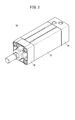
- It is a perspective view which shows an example of the external appearance of an air cylinder.
- It is a circuit diagram which shows the modification of a 1st fluid circuit.
- FIG. 1A is a circuit diagram when the switching valve of the fluid circuit (first fluid circuit) of the air cylinder according to the first embodiment is in a first state
- FIG. 1B is a driving process of the first fluid circuit.
- FIG. 2A is a circuit diagram when the switching valve of the first fluid circuit is set to the second state
- FIG. 2B is an explanatory diagram illustrating a state of the return
- FIG. 5A is a circuit diagram when the switching valve of the fluid circuit (second fluid circuit) of the air cylinder according to the second embodiment is set to the first state
- FIG. 5B is a driving process of the second fluid circuit. It is explanatory drawing which shows the state of.
- FIG. 6A is a circuit diagram when the switching valve of the second fluid circuit is set to the second state
- FIG. 6B is an explanatory diagram showing a state of the return process of the second fluid circuit. It is a circuit diagram which shows the modification of a 2nd fluid circuit.
- FIG. 10A a fluid circuit of an air cylinder according to the first embodiment (hereinafter referred to as a first fluid circuit 10A) will be described with reference to FIGS. 1A to 4.
- FIG. 10A a fluid circuit of an air cylinder according to the first embodiment
- the first fluid circuit 10A includes a first air flow path 12a, a second air flow path 12b, and a switching valve 16.
- the air cylinder 30 includes a cylinder tube 32, a head cover 34, a rod cover 36, a piston 38 (see FIG. 1A), a piston rod 40, and the like.
- One end side of the cylinder tube 32 is closed by a rod cover 36, and the other end side of the cylinder tube 32 is closed by a head cover 34.
- a piston 38 (see FIG. 1A) is disposed in the cylinder tube 32 so as to be reciprocally movable.
- the internal space of the cylinder tube 32 is, for example, as shown in FIG. 1A, a first air chamber 42a formed between the piston 38 and the rod cover 36, and a second air space formed between the piston 38 and the head cover 34. It is partitioned into an air chamber 42b.
- the piston rod 40 connected to the piston 38 cuts through the first air chamber 42a, and its end extends to the outside through the rod cover 36.
- the air cylinder 30 performs work such as positioning of a workpiece (not shown) when the piston rod 40 is pushed out (expanded), and does not work when the piston rod 40 is retracted.
- a first air passage 12 a is provided between the first air chamber 42 a of the air cylinder 30 and the switching valve 16, and a second air passage 12 b is provided between the second air chamber 42 b of the air cylinder 30 and the switching valve 16. Is provided.
- the first speed control valve 50a is a variable throttle valve of a type called meter-out, and is a control valve that can manually adjust the flow rate of air discharged from the second air chamber 42b.
- the second speed control valve 50b is a variable throttle valve of a type called meter-in, and is a control valve that can manually adjust the flow rate of air supplied to the second air chamber 42b.
- the first speed control valve 50a is configured by connecting a first check valve 52a and a first throttle valve 54a in parallel.
- the first check valve 52a allows the flow of air toward the second air chamber 42b of the air cylinder 30 via the switching valve 16, and allows the flow of air toward the switching valve 16 from the second air chamber 42b of the air cylinder 30. Stop.
- the first throttle valve 54 a adjusts the flow rate of air from the second air chamber 42 b of the air cylinder 30 toward the switching valve 16.
- the second speed control valve 50b is configured by connecting a second check valve 52b and a second throttle valve 54b in parallel.
- the second check valve 52b allows air to flow from the second air chamber 42b of the air cylinder 30 toward the switching valve 16, and allows air to flow toward the second air chamber 42b of the air cylinder 30 via the switching valve 16. Stop.
- the second throttle valve 54 b adjusts the flow rate of air toward the second air chamber 42 b of the air cylinder 30 via the switching valve 16.
- a third check valve 52c is connected to an arbitrary point between the air cylinder 30 and the first speed control valve 50a in the second air flow path 12b.
- the third check valve 52c allows air to flow from the second air passage 12b to the switching valve 16, and prevents air from flowing from the switching valve 16 to the second air passage 12b.
- the switching valve 16 has a first port 60a to a fifth port 60e and is configured as a 5-port 2-position solenoid valve that can be switched between the first position and the second position.
- the first port 60a is connected to the first air flow path 12a
- the second port 60b is connected to the second air flow path 12b.
- the third port 60 c is connected to the air supply source 62.
- the fourth port 60d is connected to an exhaust port 64 provided with a silencer 63
- the fifth port 60e is connected to the above-described third check valve 52c.
- the first port 60a and the fourth port 60d are connected, and the second port 60b and the third port 60c are connected.
- the third air flow path 12c from the third check valve 52c to the fifth port 60e of the switching valve 16 functions as one air reservoir.
- the switching valve 16 is held at the second position by the biasing force of the spring when not energized, and switches from the second position to the first position when energized.
- the energization or de-energization of the switching valve 16 is performed by outputting an energization command (energization) or an energization stop command (de-energization) from the PLC (Programmable Logic Controller), which is a host device (not shown), to the switching valve 16. .
- the switching valve 16 In the driving process of the air cylinder 30 in which the piston rod 40 is pushed out, the switching valve 16 is in the first position, and in the returning process of the air cylinder 30 in which the piston rod 40 is pulled in, the switching valve 16 is in the second position.
- a tank portion 68 is interposed at an arbitrary point of the first air flow path 12a.
- the tank portion 68 has a large volume so as to act as an air tank that accumulates air.
- 1A to 2B conceptually show the first fluid circuit 10A with circuit diagrams, and the flow path built into the air cylinder 30 is also arranged outside the air cylinder 30 for convenience. It is drawn as if it were.
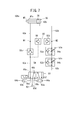
- the first air flow path 12a in the region surrounded by the one-dot chain line in FIG. 1A is provided across the rod cover 36, the cylinder tube 32, and the head cover 34 as shown in FIG.
- a portion provided at 32 is a tank portion 68.
- the tank portion 68 may be configured by a space formed between the cylinder tube 32 having a double structure including an inner tube and an outer tube.
- the first fluid circuit 10A is basically configured as described above, and the operation thereof will be described below with reference to FIGS. 1A to 2B. As shown in FIG. 1A, the state in which the switching valve 16 is in the first position and the piston rod 40 is most retracted is the initial state.
- air from the air supply source 62 is supplied to the second air chamber 42b via the second air flow path 12b, and the first air chamber
- the air in 42a is discharged from the exhaust port 64 to the outside through the first air flow path 12a.
- the second speed control valve 50b the flow rate of air is adjusted by the second throttle valve 54b, and in the first speed control valve 50a, the air is supplied to the second air chamber 42b via the first check valve 52a.
- Air from the air supply source 62 is supplied from the second air flow path 12b to the third air flow path 12c via the third check valve 52c.
- the pressure in the second air chamber 42b starts to increase and the pressure in the first air chamber 42a starts to decrease.
- the piston rod 40 starts to move in the pushing direction. As shown in FIG. 1B, the piston rod 40 extends to the maximum position and is held at that position with a large thrust.
- the switching valve 16 is switched from the first position to the second position as shown in FIGS. 2A and 2B. That is, the return process of the piston rod 40 is started.
- the air supplied toward the first air chamber 42 a is mainly accumulated in the tank unit 68.
- the largest space among the regions where air can exist between the third check valve 52c and the first air chamber 42a including the first air chamber 42a and the piping passage is defined as the largest space. This is because the tank portion 68 is occupied.
- the example in which the tank portion 68 is interposed in the first air flow path 12a is shown.
- FIG. As shown in the first fluid circuit 10Aa according to the fourth modification, the interposition of the tank portion 68 may be omitted.
- FIG. 10B a fluid circuit of the air cylinder according to the second embodiment (hereinafter referred to as a second fluid circuit 10B) will be described with reference to FIGS. 5A to 7.
- FIG. 10B a fluid circuit of the air cylinder according to the second embodiment
- the second fluid circuit 10B has substantially the same configuration as the first fluid circuit 10A described above, but differs in that it includes a bypass channel 80 instead of the third air channel 12c.
- the bypass flow path 80 is branched from the middle of the first air flow path 12a, and the bypass flow path 80 is merged in the middle of the second air flow path 12b. That is, the bypass flow path 80 is provided between the arbitrary point M1 of the first air flow path 12a and the arbitrary point M2 of the second air flow path 12b.
- the bypass flow path 80 is provided with a fourth check valve 52d on the side close to the arbitrary point M2 of the second air flow path 12b, and the pilot check valve on the side close to the arbitrary point M1 of the first air flow path 12a. 56 is interposed.
- the fourth check valve 52d allows air to flow from the second air chamber 42b to the first air chamber 42a, and prevents air from flowing from the first air chamber 42a to the second air chamber 42b.
- the pilot check valve 56 allows air to flow from the first air chamber 42a to the second air chamber 42b.
- the pilot check valve 56 prevents the flow of air from the second air chamber 42b to the first air chamber 42a when the pilot pressure higher than the predetermined pressure is not acting, and the pilot pressure higher than the predetermined pressure acts. When this is done, the flow of air from the second air chamber 42b toward the first air chamber 42a is allowed.
- the pilot check valve 56 allows the air flow from the first air chamber 42a to the second air chamber 42b and the first air from the second air chamber 42b when the pilot pressure is not acting. It functions as a check valve that prevents the flow of air toward the chamber 42a, and when pilot pressure is applied, air can flow in either direction and does not function as a check valve.
- a fifth check valve 52e is interposed in the first air flow path 12a between the arbitrary point M1 of the first air flow path 12a and the switching valve 16.
- the fifth check valve 52e allows air to flow from the arbitrary point M1 of the first air flow path 12a toward the switching valve 16, and allows the air flowing from the switching valve 16 to the arbitrary point M1 of the first air flow path 12a.
- Block distribution A pilot flow path 58 that branches from the first air flow path 12 a between the fifth check valve 52 e and the switching valve 16 and reaches the pilot check valve 56 is provided.
- the switching valve 16 of the second fluid circuit 10B also has a first port 60a to a fifth port 60e, and is configured as a 5-port 2-position solenoid valve that can be switched between the first position and the second position.
- the first port 60a is connected to the first air flow path 12a
- the second port 60b is connected to the second air flow path 12b.
- the third port 60c is connected to a first exhaust port 64a provided with a first silencer 63a.
- the fourth port 60d is connected to the air supply source 62, and the fifth port 60e is connected to the second exhaust port 64b provided with the second silencer 63b.
- a portion surrounded by a one-dot chain line that is, a tank portion 68, a bypass flow path 80 including a fourth check valve 52d and a pilot check valve 56, a pilot flow path 58, and a first check including a fifth check valve 52e.
- a part of the air flow path 12 a and a part of the second air flow path 12 b are incorporated in the air cylinder 30.
- the second fluid circuit 10B is basically configured as described above, and the operation thereof will be described below with reference to FIGS. 5A to 6B.
- the state where the switching valve 16 is in the first position and the piston rod 40 is most retracted is the initial state.
- the pressure in the second air chamber 42b starts to increase and the pressure in the first air chamber 42a starts to decrease.
- the piston rod 40 starts to move in the pushing direction. Then, as shown in FIG. 5B, the piston rod 40 extends to the maximum position and is held at that position with a large thrust.
- the switching valve 16 is switched from the first position to the second position as shown in FIG. 6A. That is, the return process of the piston rod 40 is started.
- air from the air supply source 62 flows into the first air flow path 12a between the fifth check valve 52e and the switching valve 16, and the first air blocked by the fifth check valve 52e.
- the pressure of air in the flow path 12a increases.
- the pressure in the pilot flow path 58 connected to the first air flow path 12a also exceeds a predetermined value, and the pilot check valve 56 does not function as a check valve.
- the pilot check valve 56 loses its function as a check valve, a part of the air accumulated in the second air chamber 42b passes through the arbitrary point M2 of the second air flow path 12b and passes through the fourth check valve 52d.
- the air is supplied from an arbitrary point M1 of the first air flow path 12a toward the first air chamber 42a through the bypass flow path 80 including the pilot check valve 56.
- another part of the air accumulated in the second air chamber 42b is discharged to the outside from the first exhaust port 64a via the second air flow path 12b.
- the flow rate of air is adjusted by the first throttle valve 54a, and in the second speed control valve 50b, the air flows toward the switching valve 16 via the second check valve 52b.
- the pressure in the second air chamber 42b starts to decrease and the pressure in the first air chamber 42a starts to increase.
- the air supplied toward the first air chamber 42 a is mainly accumulated in the tank unit 68.
- the fourth check valve 52d operates.
- the air in the second air chamber 42b is not supplied toward the first air chamber 42a, and the pressure in the first air chamber 42a stops increasing.
- the pressure in the second air chamber 42b continues to drop.
- the piston rod 40 When the piston rod 40 starts moving in the retracting direction, the volume of the first air chamber 42a increases, so the pressure of the first air chamber 42a decreases. However, the volume of the first air chamber 42a decreases due to the presence of the tank portion 68. It is substantially large and the rate at which the pressure drops is small. And since the pressure of the 2nd air chamber 42b falls in a bigger ratio, the state where the pressure of the 1st air chamber 42a exceeds the pressure of the 2nd air chamber 42b continues. Further, since the sliding resistance of the piston 38 which has once started to move is smaller than the frictional resistance of the piston 38 in a stationary state, the piston rod 40 can be moved in the retracting direction without any trouble. In this way, the piston rod 40 returns to the initial state where it is most retracted. This state is maintained until the switching valve 16 is switched again.
- the second fluid circuit 10B the example in which the tank portion 68 is provided in the first air flow path 12a is shown, but the inner diameter of the first air flow path 12a between the fifth check valve 52e and the first air chamber 42a. Is sufficiently large and plays the role of the tank portion 68, the interposition of the tank portion 68 may be omitted as shown in the second fluid circuit 10Ba according to the modification of FIG.
- an air cylinder 30 having a first air chamber 42a and a second air chamber 42b partitioned by a piston 38, a switching valve 16 that switches between a driving process and a returning process of the piston 38, and a first A fluid circuit of an air cylinder having a first air flow path 12a between the air chamber 42a and the switching valve 16, and a second air flow path 12b between the second air chamber 42b and the switching valve 16, Two speed control valves (first speed control valve 50a and second speed control valve 50b) are installed in series in the flow path 12b.
- the supply flow rate from the switching valve 16 to the second air chamber 42b can be adjusted by the second throttle valve 54b of the second speed control valve 50b, and in the returning process of the piston 38, the second air
- the exhaust flow rate from the chamber 42b to the switching valve 16 can be adjusted by the first throttle valve 54a of the first speed control valve 50a. That is, the supply flow rate to the air cylinder 30 and the exhaust flow rate from the air cylinder 30 can be adjusted independently. This leads to shortening of the stroke time in the driving process, which is a required characteristic of the fluid circuit, and increasing the pressure in the fluid pressure cylinder after the return process.
- the structure since it is only necessary to install two speed control valves in series in the second air flow path 12b, the structure can be simplified.
- the first check valve 52a of the first speed control valve 50a and the second throttle valve 54b of the second speed control valve 50b constitute the second air flow path 12b, and in the return process.
- the first throttle valve 54a of the first speed control valve 50a and the second check valve 52b of the second speed control valve 50b constitute the second air flow path 12b.
- the air supplied to the second air flow path 12b flows through the first check valve 52a of the first speed control valve 50a and the second throttle valve 54b of the second speed control valve 50b. It is supplied to the second air chamber 42b.
- the air exhausted from the second air chamber 42b of the air cylinder 30 to the second air flow path 12b is a second check of the first throttle valve 54a of the first speed control valve 50a and the second speed control valve 50b. The gas flows through the valve 52 b and is exhausted through the switching valve 16.
- the supply flow rate from the switching valve 16 to the second air chamber 42b can be adjusted by the second throttle valve 54b of the second speed control valve 50b, and in the return process of the piston 38, 2
- the exhaust flow rate from the air chamber 42b to the switching valve 16 can be adjusted by the first throttle valve 54a of the first speed control valve 50a.
- the third air flow path 12c is branched from the second air flow path 12b and directed to the switching valve 16, and the third air flow path 12c is provided with the second air flow path 12b side as an input.
- a third check valve 52c (outer check valve), and the third air flow path 12c stores a part of the air supplied from the second air flow path 12b in the driving process, and the third air flow path 12c. May communicate the second air flow path 12b and the first air flow path 12a via the switching valve 16 in the return step.
- the air stored in the third air flow path 12c is supplied to the first air chamber 42a of the air cylinder 30 through the switching valve 16 and the first air flow path 12a in the subsequent return process. That is, the air stored in the third air flow path 12c can be utilized as the pressure for returning the piston 38, and the consumption of air can be suppressed.
- a bypass flow path 80 provided between the first air flow path 12a and the second air flow path 12b, and a fourth check valve 52d (inner check valve) interposed in the bypass flow path 80 ) And a pilot check valve 56 (inner pilot check valve), and the fourth check valve 52d allows the air to flow from the second air chamber 42b to the first air chamber 42a, and the first air chamber 42a.
- the pilot check valve 56 permits the air flow from the first air chamber 42a to the second air chamber 42b and the pilot pressure does not act. The flow of air from the second air chamber 42b toward the first air chamber 42a may be blocked.
- the tank portion 68 may be provided near the first air chamber 42a in the first air flow path 12a. Thereby, the air discharged from the second air chamber 42b can be accumulated in the tank portion 68, and when the volume of the first air chamber 42a increases during the return process of the air cylinder 30, the pressure is increased. It is possible to suppress the decrease as much as possible.
- the fluid circuit of the air cylinder according to the present invention is not limited to the above-described embodiment, and various configurations can be adopted without departing from the gist of the present invention.
Landscapes
- Engineering & Computer Science (AREA)
- Physics & Mathematics (AREA)
- Fluid Mechanics (AREA)
- Mechanical Engineering (AREA)
- General Engineering & Computer Science (AREA)
- Fluid-Pressure Circuits (AREA)
Priority Applications (6)
| Application Number | Priority Date | Filing Date | Title |
|---|---|---|---|
| US17/251,093 US11118606B2 (en) | 2018-06-13 | 2019-06-07 | Fluid circuit of air cylinder |
| CN201980038834.2A CN112262264B (zh) | 2018-06-13 | 2019-06-07 | 气缸的流体回路 |
| KR1020217000956A KR20210020106A (ko) | 2018-06-13 | 2019-06-07 | 에어 실린더의 유체회로 |
| MX2020013548A MX2020013548A (es) | 2018-06-13 | 2019-06-07 | Circuito de fluido para cilindro de aire. |
| BR112020025458-4A BR112020025458A2 (pt) | 2018-06-13 | 2019-06-07 | Circuito de fluido do cilindro de ar |
| EP19819695.8A EP3808992A4 (en) | 2018-06-13 | 2019-06-07 | PNEUMATIC CYLINDER FLUID CIRCUIT |
Applications Claiming Priority (2)
| Application Number | Priority Date | Filing Date | Title |
|---|---|---|---|
| JP2018113156A JP7137160B2 (ja) | 2018-06-13 | 2018-06-13 | エアシリンダの流体回路 |
| JP2018-113156 | 2018-06-13 |
Publications (1)
| Publication Number | Publication Date |
|---|---|
| WO2019240023A1 true WO2019240023A1 (ja) | 2019-12-19 |
Family
ID=68841848
Family Applications (1)
| Application Number | Title | Priority Date | Filing Date |
|---|---|---|---|
| PCT/JP2019/022678 WO2019240023A1 (ja) | 2018-06-13 | 2019-06-07 | エアシリンダの流体回路 |
Country Status (9)
| Country | Link |
|---|---|
| US (1) | US11118606B2 (ko) |
| EP (1) | EP3808992A4 (ko) |
| JP (1) | JP7137160B2 (ko) |
| KR (1) | KR20210020106A (ko) |
| CN (1) | CN112262264B (ko) |
| BR (1) | BR112020025458A2 (ko) |
| MX (1) | MX2020013548A (ko) |
| TW (1) | TWI784173B (ko) |
| WO (1) | WO2019240023A1 (ko) |
Families Citing this family (5)
| Publication number | Priority date | Publication date | Assignee | Title |
|---|---|---|---|---|
| DE102019121433B4 (de) * | 2019-08-08 | 2022-12-29 | SMC Deutschland GmbH | Fluidrückführvorrichtung für einen doppeltwirkenden Zylinder und Verfahren zum Betreiben eines solchen Zylinders |
| JP2022126927A (ja) * | 2021-02-19 | 2022-08-31 | Smc株式会社 | エアシリンダの流体回路 |
| JP2022142040A (ja) * | 2021-03-16 | 2022-09-30 | トヨタ自動車株式会社 | 工場エアシステム |
| CN113719482B (zh) * | 2021-08-30 | 2023-07-18 | 湖南三一中益机械有限公司 | 液压系统和摊铺机 |
| CN116838662A (zh) * | 2023-08-30 | 2023-10-03 | 之江实验室 | 液压驱动系统及其控制方法和液压驱动肢体部件 |
Citations (3)
| Publication number | Priority date | Publication date | Assignee | Title |
|---|---|---|---|---|
| JPS5242506U (ko) * | 1975-09-22 | 1977-03-26 | ||
| JPS5555604U (ko) * | 1978-10-05 | 1980-04-15 | ||
| JP2018054117A (ja) | 2016-09-21 | 2018-04-05 | Smc株式会社 | 流体圧シリンダの駆動方法及び駆動装置 |
Family Cites Families (12)
| Publication number | Priority date | Publication date | Assignee | Title |
|---|---|---|---|---|
| US4192346A (en) * | 1976-08-25 | 1980-03-11 | Shoketsu Kinzoku Kogyo Kabushiki Kaisha | Control valve |
| JP4054938B2 (ja) * | 1998-11-05 | 2008-03-05 | Smc株式会社 | アクチュエータ制御回路 |
| JP3558556B2 (ja) * | 1999-03-10 | 2004-08-25 | Smc株式会社 | 圧力流量制御弁 |
| CN1138697C (zh) * | 2000-04-28 | 2004-02-18 | 博隆工程有限会社 | 空气平衡装置 |
| CN100526660C (zh) * | 2006-12-15 | 2009-08-12 | 北京北方微电子基地设备工艺研究中心有限责任公司 | 一种消除双作用气缸换向抖动的控制装置 |
| JP4353333B2 (ja) * | 2007-03-30 | 2009-10-28 | Smc株式会社 | 複動形エアシリンダの位置決め制御機構 |
| CN201096120Y (zh) * | 2007-04-16 | 2008-08-06 | 宝山钢铁股份有限公司 | 加热炉步进梁调速装置 |
| JP5851822B2 (ja) * | 2011-12-16 | 2016-02-03 | コベルコクレーン株式会社 | 作業機械の油圧駆動装置 |
| JP5822233B2 (ja) * | 2012-03-27 | 2015-11-24 | Kyb株式会社 | 流体圧制御装置 |
| JP5828481B2 (ja) * | 2012-07-25 | 2015-12-09 | Kyb株式会社 | 建設機械の制御装置 |
| JP5608252B2 (ja) * | 2013-02-26 | 2014-10-15 | カヤバ工業株式会社 | アクチュエータ |
| CN104235105A (zh) * | 2014-09-18 | 2014-12-24 | 芜湖高昌液压机电技术有限公司 | 龙门举升机串联速度转换回路 |
-
2018
- 2018-06-13 JP JP2018113156A patent/JP7137160B2/ja active Active
-
2019
- 2019-06-07 MX MX2020013548A patent/MX2020013548A/es unknown
- 2019-06-07 WO PCT/JP2019/022678 patent/WO2019240023A1/ja unknown
- 2019-06-07 BR BR112020025458-4A patent/BR112020025458A2/pt unknown
- 2019-06-07 CN CN201980038834.2A patent/CN112262264B/zh active Active
- 2019-06-07 US US17/251,093 patent/US11118606B2/en active Active
- 2019-06-07 KR KR1020217000956A patent/KR20210020106A/ko active Search and Examination
- 2019-06-07 EP EP19819695.8A patent/EP3808992A4/en active Pending
- 2019-06-12 TW TW108120297A patent/TWI784173B/zh active
Patent Citations (3)
| Publication number | Priority date | Publication date | Assignee | Title |
|---|---|---|---|---|
| JPS5242506U (ko) * | 1975-09-22 | 1977-03-26 | ||
| JPS5555604U (ko) * | 1978-10-05 | 1980-04-15 | ||
| JP2018054117A (ja) | 2016-09-21 | 2018-04-05 | Smc株式会社 | 流体圧シリンダの駆動方法及び駆動装置 |
Non-Patent Citations (1)
| Title |
|---|
| See also references of EP3808992A4 |
Also Published As
| Publication number | Publication date |
|---|---|
| US11118606B2 (en) | 2021-09-14 |
| KR20210020106A (ko) | 2021-02-23 |
| JP2019215051A (ja) | 2019-12-19 |
| JP7137160B2 (ja) | 2022-09-14 |
| EP3808992A4 (en) | 2022-03-16 |
| US20210131454A1 (en) | 2021-05-06 |
| MX2020013548A (es) | 2021-02-26 |
| CN112262264B (zh) | 2023-06-30 |
| EP3808992A1 (en) | 2021-04-21 |
| TWI784173B (zh) | 2022-11-21 |
| CN112262264A (zh) | 2021-01-22 |
| BR112020025458A2 (pt) | 2021-03-16 |
| TW202004031A (zh) | 2020-01-16 |
Similar Documents
| Publication | Publication Date | Title |
|---|---|---|
| WO2019240023A1 (ja) | エアシリンダの流体回路 | |
| JP5948260B2 (ja) | 流体圧制御装置 | |
| US20210404486A1 (en) | Flow rate controller and drive device comprising same | |
| KR20180071261A (ko) | 유체 제어 밸브 | |
| KR20020069108A (ko) | 쿠션기구가 부착된 실린더를 사용한 공작물의고속가압방법 및 그 기구 | |
| JP6182447B2 (ja) | 流体圧制御装置 | |
| WO2018020642A1 (ja) | 流量制御弁 | |
| KR102372065B1 (ko) | 유체압 제어 장치 | |
| US6202536B1 (en) | Pneumatic reciprocatory actuator and method of operating it | |
| JP2020085183A (ja) | 流体圧シリンダの駆動装置 | |
| JP2955220B2 (ja) | インライン増圧装置 | |
| KR20210127640A (ko) | 유체압 실린더 | |
| JP2565816Y2 (ja) | 制御弁 | |
| WO2019188127A1 (ja) | エアシリンダの流体回路 | |
| GB2530796A (en) | Actuator arrangement | |
| CN103649558A (zh) | 用于控制液压气动的压力传送装置的阀和具有阀的液压气动的压力传送装置 | |
| WO2004072487A1 (en) | Control valve for a pneumatic cylinder | |
| JPH0459484B2 (ko) | ||
| WO2015174250A1 (ja) | 流体圧制御装置 | |
| JPH0527682Y2 (ko) | ||
| JP2005282739A (ja) | シリンダ装置 | |
| WO2022022857A3 (en) | Ride control for work machines | |
| CN117916473A (zh) | 流体回路 | |
| CN116658560A (zh) | 气缸装置 | |
| JPH10331808A (ja) | 可変速流体圧シリンダ |
Legal Events
| Date | Code | Title | Description |
|---|---|---|---|
| 121 | Ep: the epo has been informed by wipo that ep was designated in this application |
Ref document number: 19819695 Country of ref document: EP Kind code of ref document: A1 |
|
| NENP | Non-entry into the national phase |
Ref country code: DE |
|
| REG | Reference to national code |
Ref country code: BR Ref legal event code: B01A Ref document number: 112020025458 Country of ref document: BR |
|
| ENP | Entry into the national phase |
Ref document number: 20217000956 Country of ref document: KR Kind code of ref document: A |
|
| ENP | Entry into the national phase |
Ref document number: 2019819695 Country of ref document: EP Effective date: 20210113 |
|
| ENP | Entry into the national phase |
Ref document number: 112020025458 Country of ref document: BR Kind code of ref document: A2 Effective date: 20201212 |