WO2019239671A1 - コイル封入圧粉成形コア、インダクタンス素子、および電子・電気機器 - Google Patents
コイル封入圧粉成形コア、インダクタンス素子、および電子・電気機器 Download PDFInfo
- Publication number
- WO2019239671A1 WO2019239671A1 PCT/JP2019/011818 JP2019011818W WO2019239671A1 WO 2019239671 A1 WO2019239671 A1 WO 2019239671A1 JP 2019011818 W JP2019011818 W JP 2019011818W WO 2019239671 A1 WO2019239671 A1 WO 2019239671A1
- Authority
- WO
- WIPO (PCT)
- Prior art keywords
- coil
- core
- dust
- volume
- powder
- Prior art date
- Legal status (The legal status is an assumption and is not a legal conclusion. Google has not performed a legal analysis and makes no representation as to the accuracy of the status listed.)
- Ceased
Links
Images




Classifications
-
- H—ELECTRICITY
- H01—ELECTRIC ELEMENTS
- H01F—MAGNETS; INDUCTANCES; TRANSFORMERS; SELECTION OF MATERIALS FOR THEIR MAGNETIC PROPERTIES
- H01F27/00—Details of transformers or inductances, in general
- H01F27/24—Magnetic cores
- H01F27/255—Magnetic cores made from particles
-
- H—ELECTRICITY
- H01—ELECTRIC ELEMENTS
- H01F—MAGNETS; INDUCTANCES; TRANSFORMERS; SELECTION OF MATERIALS FOR THEIR MAGNETIC PROPERTIES
- H01F17/00—Fixed inductances of the signal type
- H01F17/04—Fixed inductances of the signal type with magnetic core
-
- H—ELECTRICITY
- H01—ELECTRIC ELEMENTS
- H01F—MAGNETS; INDUCTANCES; TRANSFORMERS; SELECTION OF MATERIALS FOR THEIR MAGNETIC PROPERTIES
- H01F37/00—Fixed inductances not covered by group H01F17/00
-
- H—ELECTRICITY
- H01—ELECTRIC ELEMENTS
- H01F—MAGNETS; INDUCTANCES; TRANSFORMERS; SELECTION OF MATERIALS FOR THEIR MAGNETIC PROPERTIES
- H01F41/00—Apparatus or processes specially adapted for manufacturing or assembling magnets, inductances or transformers; Apparatus or processes specially adapted for manufacturing materials characterised by their magnetic properties
- H01F41/02—Apparatus or processes specially adapted for manufacturing or assembling magnets, inductances or transformers; Apparatus or processes specially adapted for manufacturing materials characterised by their magnetic properties for manufacturing cores, coils, or magnets
- H01F41/0206—Manufacturing of magnetic cores by mechanical means
- H01F41/0246—Manufacturing of magnetic circuits by moulding or by pressing powder
-
- H—ELECTRICITY
- H01—ELECTRIC ELEMENTS
- H01F—MAGNETS; INDUCTANCES; TRANSFORMERS; SELECTION OF MATERIALS FOR THEIR MAGNETIC PROPERTIES
- H01F1/00—Magnets or magnetic bodies characterised by the magnetic materials therefor; Selection of materials for their magnetic properties
- H01F1/01—Magnets or magnetic bodies characterised by the magnetic materials therefor; Selection of materials for their magnetic properties of inorganic materials
- H01F1/03—Magnets or magnetic bodies characterised by the magnetic materials therefor; Selection of materials for their magnetic properties of inorganic materials characterised by their coercivity
- H01F1/12—Magnets or magnetic bodies characterised by the magnetic materials therefor; Selection of materials for their magnetic properties of inorganic materials characterised by their coercivity of soft-magnetic materials
- H01F1/14—Magnets or magnetic bodies characterised by the magnetic materials therefor; Selection of materials for their magnetic properties of inorganic materials characterised by their coercivity of soft-magnetic materials metals or alloys
- H01F1/147—Alloys characterised by their composition
- H01F1/153—Amorphous metallic alloys, e.g. glassy metals
- H01F1/15358—Making agglomerates therefrom, e.g. by pressing
- H01F1/15366—Making agglomerates therefrom, e.g. by pressing using a binder
- H01F1/15375—Making agglomerates therefrom, e.g. by pressing using a binder using polymers
-
- H—ELECTRICITY
- H01—ELECTRIC ELEMENTS
- H01F—MAGNETS; INDUCTANCES; TRANSFORMERS; SELECTION OF MATERIALS FOR THEIR MAGNETIC PROPERTIES
- H01F1/00—Magnets or magnetic bodies characterised by the magnetic materials therefor; Selection of materials for their magnetic properties
- H01F1/01—Magnets or magnetic bodies characterised by the magnetic materials therefor; Selection of materials for their magnetic properties of inorganic materials
- H01F1/03—Magnets or magnetic bodies characterised by the magnetic materials therefor; Selection of materials for their magnetic properties of inorganic materials characterised by their coercivity
- H01F1/12—Magnets or magnetic bodies characterised by the magnetic materials therefor; Selection of materials for their magnetic properties of inorganic materials characterised by their coercivity of soft-magnetic materials
- H01F1/14—Magnets or magnetic bodies characterised by the magnetic materials therefor; Selection of materials for their magnetic properties of inorganic materials characterised by their coercivity of soft-magnetic materials metals or alloys
- H01F1/20—Magnets or magnetic bodies characterised by the magnetic materials therefor; Selection of materials for their magnetic properties of inorganic materials characterised by their coercivity of soft-magnetic materials metals or alloys in the form of particles, e.g. powder
- H01F1/22—Magnets or magnetic bodies characterised by the magnetic materials therefor; Selection of materials for their magnetic properties of inorganic materials characterised by their coercivity of soft-magnetic materials metals or alloys in the form of particles, e.g. powder pressed, sintered, or bound together
- H01F1/24—Magnets or magnetic bodies characterised by the magnetic materials therefor; Selection of materials for their magnetic properties of inorganic materials characterised by their coercivity of soft-magnetic materials metals or alloys in the form of particles, e.g. powder pressed, sintered, or bound together the particles being insulated
- H01F1/26—Magnets or magnetic bodies characterised by the magnetic materials therefor; Selection of materials for their magnetic properties of inorganic materials characterised by their coercivity of soft-magnetic materials metals or alloys in the form of particles, e.g. powder pressed, sintered, or bound together the particles being insulated by macromolecular organic substances
-
- H—ELECTRICITY
- H01—ELECTRIC ELEMENTS
- H01F—MAGNETS; INDUCTANCES; TRANSFORMERS; SELECTION OF MATERIALS FOR THEIR MAGNETIC PROPERTIES
- H01F17/00—Fixed inductances of the signal type
- H01F17/04—Fixed inductances of the signal type with magnetic core
- H01F17/045—Fixed inductances of the signal type with magnetic core with core of cylindric geometry and coil wound along its longitudinal axis, i.e. rod or drum core
- H01F2017/046—Fixed inductances of the signal type with magnetic core with core of cylindric geometry and coil wound along its longitudinal axis, i.e. rod or drum core helical coil made of flat wire, e.g. with smaller extension of wire cross section in the direction of the longitudinal axis
-
- H—ELECTRICITY
- H01—ELECTRIC ELEMENTS
- H01F—MAGNETS; INDUCTANCES; TRANSFORMERS; SELECTION OF MATERIALS FOR THEIR MAGNETIC PROPERTIES
- H01F17/00—Fixed inductances of the signal type
- H01F17/04—Fixed inductances of the signal type with magnetic core
- H01F2017/048—Fixed inductances of the signal type with magnetic core with encapsulating core, e.g. made of resin and magnetic powder
-
- H—ELECTRICITY
- H01—ELECTRIC ELEMENTS
- H01F—MAGNETS; INDUCTANCES; TRANSFORMERS; SELECTION OF MATERIALS FOR THEIR MAGNETIC PROPERTIES
- H01F27/00—Details of transformers or inductances, in general
- H01F27/28—Coils; Windings; Conductive connections
- H01F27/2847—Sheets; Strips
- H01F27/2852—Construction of conductive connections, of leads
Definitions
- the present invention relates to a coil-embedded dust-molded core, an inductance element provided with the coil-filled dust-molded core, and an electronic / electrical device on which the inductance element is mounted.
- an “inductance element” is a passive element including a core material including a dust core and a coil, and includes a concept of a reactor.
- the volume of the coil-embedded dust-molded core cannot be increased. For this reason, the volume of the compacting core in the coil-filled compacting core is relatively reduced. As a result, the direct current superimposition characteristic of the inductance element may be deteriorated.
- the size of the coil-embedded dust core provided in the inductance element is several millimeters square, there is a practical limit to reducing the coil volume from the viewpoint of securing the self-inductance L required for the inductance element. is there. For this reason, it has been extremely difficult to obtain a coil-enclosed dust-molded core having a necessary self-inductance L and improved DC superposition characteristics.
- an object of the present invention is to provide a coil-embedded dust core that constitutes an inductance element capable of improving the DC superposition characteristics while maintaining basic characteristics (particularly L / DCR).
- Another object of the present invention is to provide an inductance element provided with the above-described coil-enclosed dust-molded core, and an electronic / electric device on which the inductance element is mounted.
- the coil winding body disposed inside the coil-embedded dust-molded core is set in relation to the dust-molded core so as to reduce the inductance.
- Isat ⁇ L / DCR which is an index for comprehensive evaluation of the basic characteristics and direct current superimposition characteristics of the element, can be stably increased.
- One aspect of the present invention is a coil-embedded dust-molded core in which a coil having a wound body is enclosed in a dust-molded core containing magnetic powder, and the internal core volume ratio RV defined below is 3 or more and 5
- RV (V1 / V2) / (1-V / Vp)
- V1 is inside the winding body of the coil when the coil-enclosed dust-forming core is viewed from a first direction that is a direction along the winding axis of the coil in the dust-forming core.
- V2 is the volume (first volume) of the region (first region) located, and V2 is the winding of the coil when the coil-enclosed dust-forming core is viewed from the first direction in the dust-forming core.
- the volume (second volume) of the region (second region) located outside the body, V is the volume (core volume) of the dust-molded core, and Vp is the volume of the coil-filled dust-molded core ( Chip volume).
- the internal core volume ratio RV is a value obtained by standardizing V1 / V2 by the ratio (1-V / Vp) of the coil volume to the chip volume Vp, and the sum of the coil volume and the core volume V is the chip volume Vp. become. Due to the different non-linear relationship, Isat ⁇ L / DCR, which is positioned as an index for comprehensive evaluation of the characteristics of the inductance element, shows a tendency that the inner core volume ratio RV has a peak in the range of 3 to 5. This tendency is recognized even when the composition of the magnetic powder contained in the dust core and the method for producing the dust core are different.
- the composition of the magnetic powder and the method of manufacturing the dust core are related. Therefore, it is easy to obtain good characteristics of the inductance element.
- the magnetic powder included in the compacted core may be at least partially made of an amorphous magnetic material, and more specifically, may be made of an amorphous magnetic material and a crystalline magnetic material.
- the magnetic powder included in the compacting core may be composed of only an amorphous magnetic material or only a crystalline magnetic material.
- crystalline magnetic materials include Fe—Si—Cr alloys, Fe—Ni alloys, Fe—Co alloys, Fe—V alloys, Fe—Al alloys, Fe—Si alloys, Fe—Si. -Al-based alloys, carbonyl iron and pure iron are mentioned, and the crystalline magnetic material may contain one or more materials selected from the group consisting of these alloys. In some cases, the crystalline magnetic material is preferably composed of an Fe—Si—Cr alloy.
- the amorphous magnetic material examples include an Fe—Si—B alloy, an Fe—PC alloy, and a Co—Fe—Si—B alloy, and the amorphous magnetic material includes these alloys. One or two or more materials selected from the group may be included. In some cases, the amorphous magnetic material is preferably made of an Fe—PC alloy.
- an inductance element including the above-described coil-enclosed dust-molded core and a connection terminal connected to each end of the coil included in the coil-enclosed dust-form core.
- Such an inductance element can improve the direct current superposition characteristics while maintaining the basic characteristics (L / DCR) based on the excellent characteristics of the above-described coil-embedded dust core.
- Still another aspect of the present invention is an electronic / electrical device in which the inductance element is mounted, and the inductance element is an electronic / electrical device connected to a substrate by the connection terminal.
- Examples of such electronic / electrical equipment include a power supply device including a power supply switching circuit, a voltage raising / lowering circuit, and a smoothing circuit, and a small portable communication device. Since the electronic / electrical equipment according to the present invention includes the above-described inductance element, it is easy to cope with downsizing.
- the inductance provided with such a coil-filled dust-formed core about an element, it is possible to improve a direct current superimposition characteristic, maintaining a basic characteristic (L / DCR).
- an inductance element provided with the above-described coil-enclosed dust-molded core, and an electronic / electrical device on which the inductance element is mounted are provided.
- FIG. 3A is a top view of a coil-embedded dust molding core according to an embodiment of the present invention
- FIG. 2B is a cross-sectional view taken along line AA in FIG. 4A is a top view of a coil-embedded dust compact core to be simulated
- FIG. 3B is a cross-sectional view taken along line A1-A1 of FIG.
- (b) A top view of a coil-filled dust-forming core according to Calculation Example 1-6 It is the graph which showed the relationship between DCR and RV. It is the graph which showed the relationship between L and RV. It is the graph which showed the relationship between Isat and RV. It is the graph which showed the relationship between Isat * L / DCR and RV.
- FIG. 1 is a perspective view conceptually showing the shape of an inductance element including a coil-embedded dust core according to an embodiment of the present invention.
- FIG. 2A is a top view of a coil-embedded dust-molded core according to an embodiment of the present invention.
- FIG. 2B is a cross-sectional view taken along the line AA in FIG.
- An inductance element 100 according to an embodiment of the present invention has a powder compact including a magnetic powder, and has a compact or cuboid compact core 30 and terminal portions 20 and 25 at both ends of the wound body 10C.
- a coil-embedded dust molding core 100A in which the coil 10 is embedded is provided.
- the coil 10 which is an edgewise coil, is made of a conductive metal material coated with an insulating material, and is formed by winding a conductive band that is a band having a rectangular cross section.
- the plate surface of the conductive band is substantially perpendicular to the winding axis (the direction along the Z1-Z2 direction) (that is, the surface along the XY plane). It is wound so that the side end face of the conductive band that determines the thickness direction of the wound body 10C is parallel to the winding axis, and the plate surfaces of the conductive band overlap with each other along the winding axis. ing.
- the upper and lower end surfaces (both end surfaces in the Z1-Z2 direction) of the wound body 10C have a normal line along the winding axis of the wound body 10C.
- the cross-sectional shape of the coil 10 is not limited.
- the cross-sectional shape of the coil 10 may be a circle (round line).
- the cross-sectional shape of the coil 10 is a rectangle such as a rectangle as described above, the occupation ratio of the wound body 10C can be increased, which is preferable.
- the coil 10 may be ⁇ -winding instead of the edgewise coil as described above.
- the specific composition of the conductive metal material is not limited.
- a good conductor such as copper, copper alloy, aluminum or aluminum alloy is preferable.
- the type of insulating material that coats the conductive metal material is not limited. Specific examples of suitable materials include resin-based materials such as enamel. In the case where the coil 10 is an edgewise coil, the insulating material located on the outer surface side is easily stretched. Therefore, it is preferable to use a material that does not easily lower the insulation even when such stretching is performed.
- both ends of the conductive band constituting the coil 10 protrude and are further folded, and a portion close to the end of the conductive band is a terminal.
- the parts 20 and 25 are configured. As shown in FIG. 1, the terminal portion 20 located at one end of the conductive band constituting the coil 10 is bent a plurality of times, and part of the terminal portion 20 protrudes from the inside of the dust-molded core 30 and is electrically conductive from this portion. The part reaching the end of the sex band is located outside the compacting core 30. That is, the distal end portion of the terminal portion 20 is located outside the powder molding core 30.
- a plurality of terminal portions 25 located at the other end of the conductive band constituting the coil 10 are also bent and bent, and a part protrudes from the inside of the dust-molded core 30 to reach the end of the conductive band.
- the part is located outside the green compact core 30. That is, the distal end portion of the terminal portion 25 is located outside the powder molding core 30.
- the wound body 10 ⁇ / b> C and the terminal portions 20 and 25 are composed of the same member (conductive band), but are not limited thereto.
- Separate members may be joined to the end portions of the conductive band constituting the wound body 10 ⁇ / b> C, and these members may be the terminal portions 20 and 25 of the coil 10.
- the inductance element 100 includes a pair of coating-type electrodes 40 and 45 as connection terminals.
- the pair of coating-type electrodes 40 and 45 is electrically connected to each of the terminal portions 20 and 25 on the upper surface of the powder molding core 30 and is further provided on a part of the side surface of the powder molding core 30.
- Application portions 40a and 45a are provided.
- the coating-type electrodes 40, 45 are opposed to the side surface of the powder molding core 30 where the portion protruding from the powder molding core 30 in the conductive band constituting the coil 10 is located and the side surface thereof. It is also provided on a part of the side surface.
- plating made of a metal element such as nickel or tin is provided on the coating type electrodes 40 and 45 in order to improve the adhesiveness with the solder used for mounting on the circuit board.
- a film may be applied.
- an electrode film may be formed on the powder-molded core 30 by means such as sputtering or plating to constitute the connection terminal.
- the wound body 10 ⁇ / b> C of the coil 10 is embedded in the dust core 30. Since the wound body 10C is edgewise wound, the conductive band forming the wound body 10C is wound around a winding axis along the Z1-Z2 direction.
- the winding method of the conductive band in the wound body 10 ⁇ / b> C is edgewise winding, but other winding methods such as ⁇ winding may be used.
- the compacting core 30 includes magnetic powder, and in this embodiment, at least a part thereof is made of a powder of an amorphous magnetic material.
- the magnetic powder contains a crystalline magnetic material powder and an amorphous magnetic material powder. Further, these crystalline magnetic material powder and amorphous magnetic material powder may be mixed with other materials contained in the compacting core 30 (they may be the same type of material or different types of materials).
- the compacting core 30 contains a binding component that binds to a certain component).
- the binder component has at least one selected from a resin and a heat-modified product of the resin.
- the binder component may contain an inorganic material such as water glass. Note that the magnetic powder included in the compacting core may be composed of only an amorphous magnetic material or only a crystalline magnetic material.
- the crystalline magnetic material that gives the powder of the crystalline magnetic material contained in the compacting core 30 is crystalline (diffraction having a clear peak to the extent that the material type can be specified by general X-ray diffraction measurement).
- the specific type is not limited as long as a spectrum can be obtained) and a ferromagnetic material, particularly a soft magnetic material is satisfied.
- Specific examples of crystalline magnetic materials include Fe—Si—Cr alloys, Fe—Ni alloys, Fe—Co alloys, Fe—V alloys, Fe—Al alloys, Fe—Si alloys, Fe—Si. -Al based alloys, carbonyl iron and pure iron.
- Said crystalline magnetic material may be comprised from one type of material, and may be comprised from multiple types of material.
- the crystalline magnetic material that gives the powder of the crystalline magnetic material is preferably one or more materials selected from the group consisting of the above materials, and among these, an Fe—Si—Cr alloy is used. It is preferably contained, and more preferably made of a Fe—Si—Cr alloy. Since the Fe—Si—Cr alloy is a material capable of relatively reducing the iron loss Pcv among the crystalline magnetic materials, the content of the crystalline magnetic material powder in the compacting core 30 and the amorphous Even if the mass ratio of the content of the crystalline magnetic material powder to the total content of the powder of the magnetic magnetic material (also referred to as “first mixing ratio” in this specification) is increased, The iron loss Pcv of the inductance element 100 provided is difficult to increase.
- the Si content and the Cr content in the Fe—Si—Cr alloy are not limited. A non-limiting example is that the Si content is about 2 to 7% by mass and the Cr content is about 2 to 7% by mass.
- the shape of the powder of the crystalline magnetic material contained in the compacting core 30 is not limited.
- the shape of the powder may be spherical or non-spherical. Since the crystalline magnetic material is relatively softer than the amorphous magnetic material, the crystalline magnetic material may have an indeterminate shape positioned between the powders of the amorphous magnetic material in the powder compacting core 30. . It may be preferable that the content of the crystalline magnetic material powder in the green compact core 30 is such that the first mixing ratio is 30% by mass or more and 70% by mass or less. As will be described later, from the viewpoint of obtaining the basic characteristics and direct current superimposition characteristics of the inductance element 100 at a higher level, the first mixing ratio may be preferably 30% by mass or more and 55% by mass or less.
- the powder of the crystalline magnetic material is made of a material subjected to surface insulation treatment, and the powder of the crystalline magnetic material is more preferably made of a material subjected to surface insulation treatment.
- the surface insulation treatment is performed on the powder of the crystalline magnetic material, the insulation resistance of the green compact core 30 tends to be improved.
- the type of surface insulation treatment applied to the crystalline magnetic material powder is not limited. Examples include phosphoric acid treatment, phosphate treatment, and oxidation treatment.
- the amorphous magnetic material that gives the powder of the amorphous magnetic material contained in the compacting core 30 is amorphous (a peak that is clear enough to identify the material type by general X-ray diffraction measurement).
- the specific type is not limited as long as it satisfies that the diffraction spectrum having the above can not be obtained) and that it is a ferromagnetic material, particularly a soft magnetic material.
- Specific examples of the amorphous magnetic material include Fe—Si—B alloys, Fe—PC alloys, and Co—Fe—Si—B alloys.
- Said amorphous magnetic material may be comprised from one type of material, and may be comprised from multiple types of material.
- the magnetic material constituting the powder of the amorphous magnetic material is preferably one or two or more materials selected from the group consisting of the above materials, and among these, an Fe—PC alloy is used. It is preferably contained, and more preferably made of an Fe—PC alloy.
- An inductance element 100 having a powdered core 30 using a powder of an amorphous magnetic material made of an Fe-PC-based alloy as a magnetic powder has a low iron loss Pcv. However, as a general tendency, the DC superposition characteristic tends to be low. . Therefore, when the coil-embedded dust forming core 100A according to one embodiment of the present invention includes magnetic powder of Fe—PC system alloy, the core loss Pcv based on Fe—PC system alloy is enjoyed. However, good direct current superposition characteristics can be obtained.
- Fe-P-C-based alloy composition formula, shown in Fe 100 atomic% -a-b-c-x -y-z-t Ni a Sn b Cr c P x C y B z Si t 0 atom% ⁇ a ⁇ 10 atom%, 0 atom% ⁇ b ⁇ 3 atom%, 0 atom% ⁇ c ⁇ 6 atom%, 6.8 atom% ⁇ x ⁇ 13 atom%, 2.2 atom% ⁇
- Fe-based amorphous alloys in which y ⁇ 13 atomic%, 0 atomic% ⁇ z ⁇ 9 atomic%, and 0 atomic% ⁇ t ⁇ 7 atomic%.
- Ni, Sn, Cr, B, and Si are optional added elements.
- the addition amount a of Ni is preferably 0 atom% or more and 6 atom% or less, and more preferably 0 atom% or more and 4 atom% or less.
- the addition amount b of Sn is preferably 0 atom% or more and 2 atom% or less, and may be added in a range of 1 atom% or more and 2 atom% or less.
- the addition amount c of Cr is preferably 0 atom% or more and 2 atom% or less, and more preferably 1 atom% or more and 2 atom% or less.
- the addition amount x of P is preferably 8.8 atomic% or more.
- the addition amount y of C may be preferably 5.8 atomic% or more and 8.8 atomic% or less.
- the addition amount z of B is preferably 0 atom% or more and 3 atom% or less, and more preferably 0 atom% or more and 2 atom% or less.
- the addition amount t of Si is preferably 0 atom% or more and 6 atom% or less, and more preferably 0 atom% or more and 2 atom% or less.
- the shape of the powder of the amorphous magnetic material contained in the compacting core 30 is not limited. It may be spherical, elliptical, scaly, or have an indefinite shape. In some cases, the amorphous magnetic material can be easily formed into a spherical shape or an elliptical spherical shape because of the manufacturing method. In general, since an amorphous magnetic material is harder than a crystalline magnetic material, it may be preferable to make the crystalline magnetic material non-spherical so that it is easily deformed during pressure molding.
- the shape of the powder of the amorphous magnetic material contained in the compacting core 30 may be the shape obtained at the stage of producing the powder, or obtained by secondary processing of the produced powder. It may be a shape. Examples of the former shape include a sphere, an oval sphere, and a needle shape, and examples of the latter shape include a scale shape.
- the particle size of the powder of the amorphous magnetic material contained in the green compact core 30 is a particle size (in the present specification, “median” in which the cumulative particle size distribution from the small particle size side is 50% in the volume-based particle size distribution. Also referred to as “diameter.”) D 50 A is preferably 15 ⁇ m or less. When the median diameter D 50 A of the powder of the amorphous magnetic material is 15 ⁇ m or less, it is easy to reduce the iron loss Pcv while improving the direct current superposition characteristics of the inductance element 100 including the dust core 30.
- the median diameter D 50 A of the powder of the amorphous magnetic material is: In some cases, it is preferably 10 ⁇ m or less, more preferably 7 ⁇ m or less, and particularly preferably 5 ⁇ m or less.
- the compacting core 30 contains a binding component that binds the powder of the crystalline magnetic material and the powder of the amorphous magnetic material to other materials contained in the compacting core 30.
- the composition of the binder component is not limited as long as it is a material that contributes to fixing the magnetic powder contained in the green compact core 30 according to the present embodiment.
- an organic material such as a resin material and a thermal decomposition residue of the resin material (in this specification, these are collectively referred to as “components based on a resin material”), an inorganic material, and the like
- the resin material include acrylic resin, silicone resin, epoxy resin, phenol resin, urea resin, and melamine resin.
- the binder component made of an inorganic material is exemplified by a glass-based material such as water glass.
- the binder component may be composed of one type of material or may be composed of a plurality of materials.
- the binder component may be a mixture of an organic material and an inorganic material.
- An insulating material is usually used as a binding component. Thereby, it becomes possible to improve the insulation as the compacting core 30.
- the manufacturing method of the green compact core 30 includes a molding step of molding a powder containing magnetic powder to obtain a molded product, and a heat treatment step of heating the molded product as necessary.
- a mixture containing a magnetic powder and a component that provides a binding component in the compacting core 30 is prepared.
- the component that gives the binding component (also referred to as “binder component” in this specification) may be the binding component itself or may be a material different from the binding component. Specific examples of the latter include a case where the binder component is a resin material and the binder component is a thermal decomposition residue thereof.
- a molded product can be obtained by a molding process including pressure molding of this mixture.
- the pressurizing condition is not limited and is appropriately determined based on the composition of the binder component.
- the binder component is made of a thermosetting resin, it is preferable to heat the resin together with pressure to advance the resin curing reaction in the mold.
- the pressing force is high, heating is not a necessary condition and pressurization is performed for a short time.
- the pressurizing condition in the case of compression molding is exemplified by 0.3 GPa or more and 2 GPa or less, and preferably 0.5 GPa or more and 2 GPa or less, and may be a preferable example, and may be 0.8 GPa or more and 2 GPa or less. May be a more preferred example.
- pressurization may be performed while heating, or pressurization may be performed at room temperature.
- the molded product obtained by the molding process may be the powder molded core 30 according to the present embodiment, or as will be described below, the molded product is subjected to a heat treatment step and the powder molded core 30 is processed. You may get In the heat treatment process, the molded product obtained by the above molding process is heated to adjust the magnetic properties by correcting the distance between the magnetic powders and to relax the strain applied to the magnetic powder in the molding process. The magnetic property is adjusted to obtain the green compact core 30.
- the heat treatment conditions such as the heat treatment temperature are set so that the magnetic properties of the powder molded core 30 are the best.
- a method for setting the heat treatment conditions it is possible to change the heating temperature of the molded product and to make other conditions constant, such as the heating rate and the holding time at the heating temperature.
- the evaluation criteria for the magnetic properties of the green compact core 30 when setting the heat treatment conditions are not particularly limited.
- the iron loss Pcv of the powder molded core 30 can be given. In this case, what is necessary is just to set the heating temperature of a molded product so that the iron loss Pcv of the compacting core 30 may become the minimum.
- the measurement conditions for the iron loss Pcv are set as appropriate. As an example, a condition in which the frequency is 100 kHz and the effective maximum magnetic flux density Bm is 100 mT can be given.
- the atmosphere during the heat treatment is not particularly limited.
- an oxidizing atmosphere the possibility of excessive thermal decomposition of the binder component and the possibility of progress of oxidation of the magnetic powder increases, so that an inert atmosphere such as nitrogen or argon, or a reducing property such as hydrogen Heat treatment is preferably performed in an atmosphere.
- an inert atmosphere such as nitrogen or argon, or a reducing property such as hydrogen Heat treatment is preferably performed in an atmosphere.
- a non-limiting example of the heat treatment temperature is a range of 200 ° C. to 400 ° C.
- FIG. 3A is a top view of a coil-embedded dust molding core to be simulated
- FIG. 3B is a cross-sectional view taken along line A1-A1 of FIG. Note that this simulation is performed using an edgewise coil using a rectangular wire.
- V is the volume of the core region
- Vc is the volume of the coil region.
- the core region is configured by the following first region 31 to third region 33.
- the first region 31 is located on the inner side of the wound body 10C when the coil-embedded dust core 100A is viewed from the first direction (Z1-Z2 direction) that is the direction along the winding axis of the wound body 10C. This is the area that is located.
- the second region 32 is a region located outside the wound body 10C when the coil-embedded dust molding core 100A is viewed from the first direction (Z1-Z2 direction).
- the third region 33 is a region that overlaps with the wound body 10C when the coil-embedded dust core 100A is viewed from the first direction (Z1-Z2 direction).
- the volume (first volume) of the first region 31 is V1
- the volume (second volume) of the second region 32 is V2
- the volume (third volume) of the third region 33 is V3
- the increase in the first volume V1 results in an increase in self-inductance L and an improvement in DC superposition characteristics (specifically, an increase in Isat).
- the increase in the first volume V1 also increases the length of the wound body 10C located around the first region 31, and thus increases the DC resistance component DCR of the coil 10.
- the increase in the first volume V1 results in a decrease in the volume of the second region 32 (second volume V2).
- the decrease in the second volume V2 affects the characteristics of the inductance element 100.
- RV (V1 / V2) / (1-V / Vp)
- the effect of V2 can be evaluated.
- the dust forming provided in the coil-embedded dust forming core 100A is performed.
- the influence which the material which comprises the core 30 differs on various characteristics was confirmed (calculation example 1-calculation example 3).
- the compacting core used for the measurement of magnetic properties had the shape of a toroidal core having an outer diameter of 20 mm, an inner diameter of 12 mm, and a thickness of 3 mm.
- the magnetic powder contained in the compacted core is a mixed powder of a powder of an amorphous magnetic material made of Fe-PC system alloy and a powder of a crystalline magnetic material made of Fe-Si-Cr system alloy.
- the mass ratio (first mixing ratio) of the crystalline magnetic material powder content to the sum of the crystalline magnetic material powder content and the amorphous magnetic material powder content in the compacted core is: It selected from the range of 30 mass% or more and 55 mass% or less.
- the compression molding conditions were appropriately selected from the range of 0.5 GPa to 1.5 GPa and the heat treatment conditions were appropriately selected from the range of 300 ° C to 450 ° C. More specifically, the content ratio of the crystalline magnetic powder in the magnetic powder in the powder molding core (core number 2) according to calculation example 2 based on the powder molding core according to calculation example 1 (core number 1). was relatively high and the molding pressure was relatively low.
- Table 1 shows the results of measuring the magnetic properties of these three types of compacted cores (core numbers 1 to 3).
- the frequency of the magnetic field applied in the measurement of the magnetic permeability ⁇ 5500 in the initial magnetic permeability ⁇ and a magnetic field of 5500 A / m was 100 kHz.
- the measurement of Isat (unit: A) was performed by winding a coil around a toroidal core for 34 turns.
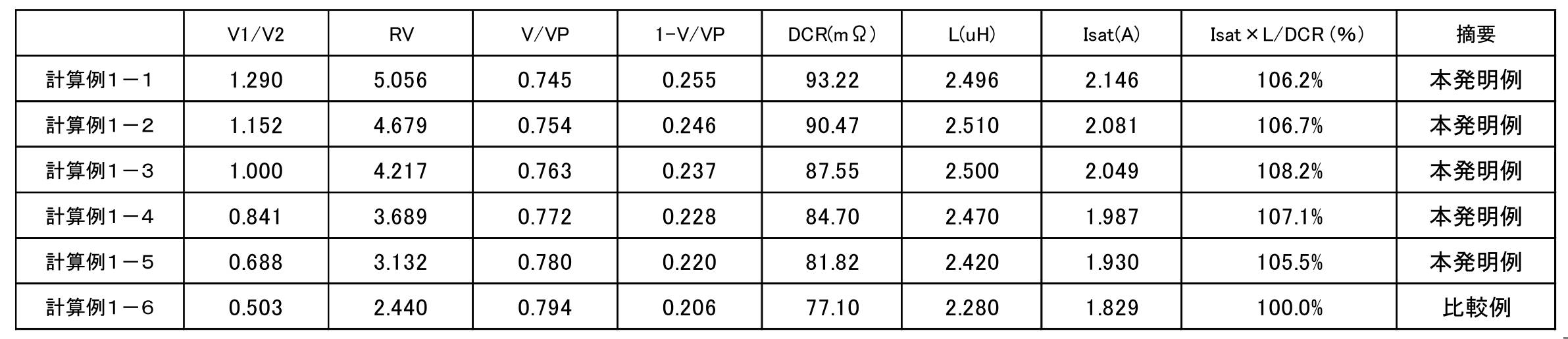
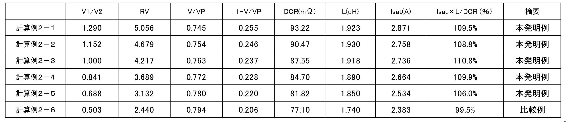
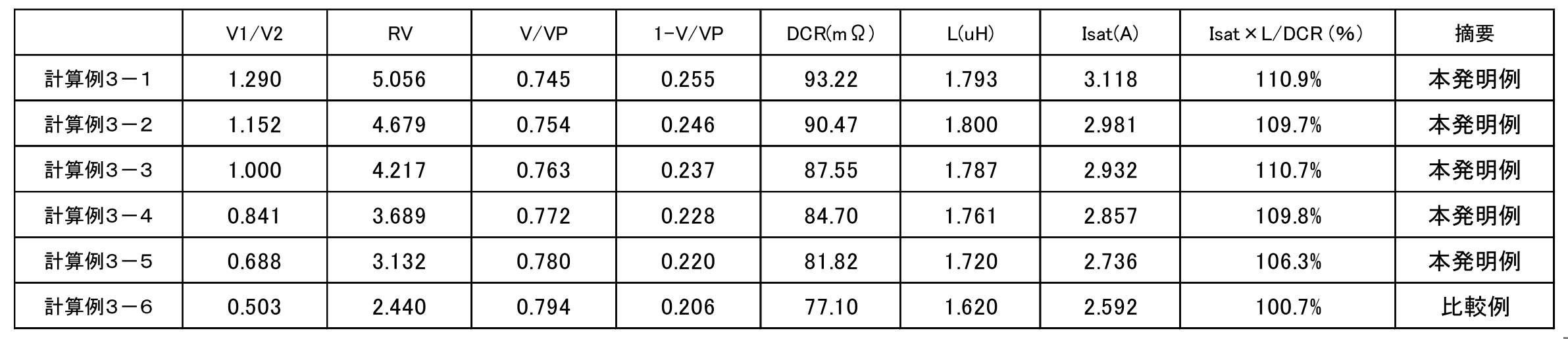
- Table 2 shows the results of Calculation Example 1
- Table 3 shows the results of Calculation Example 2
- Table 4 shows the results of Calculation Example 3.
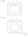
- the RV decreases from the calculation example 1-1 to the calculation example 1-6. Therefore, as shown in FIG. 4, the wound body 10C in the coil-embedded dust compacting core 100A (FIG. 4 (a)) according to Calculation Example 1-1 is composed of the coil-filled dust compact according to Calculation Example 1-6. It is located on the outer peripheral side from the wound body 10C in the molded core 100A (FIG. 4B).
- the self-inductance L has a peak when the inner core volume ratio RV is about 4.5. Due to the influence of the material constituting the green compact core 30, as a general trend, the self-inductance L of calculation example 1 is higher than the self-inductance L of calculation example 2, and the self-inductance L of calculation example 2 is the self-inductance of calculation example 3 It is higher than the inductance L.
- the material constituting the green compact core 30 has little influence on Isat ⁇ L / DCR as a comprehensive evaluation.
- the volume ratio RV is high, specifically, when it exceeds 3, it was also confirmed that the material constituting the green compact core 30 has a large influence on Isat ⁇ L / DCR as a comprehensive evaluation.
- an edgewise coil using a flat wire was used, but it was confirmed that the same result was obtained with an ⁇ coil using a flat wire.
- An electronic / electric device is an electronic / electric device in which the inductance element 100 according to the above-described embodiment of the present invention is mounted, and the coil 10 included in the coil-embedded dust core 100A. Are connected to the substrate by connection terminals (coating electrodes 40, 45) connected to respective end portions (terminal portions 20, 25). Since the electronic device according to the embodiment of the present invention is mounted with the inductance element 100 according to the embodiment of the present invention, the device can be easily downsized. Further, even if a large current is passed through the device or a high frequency is applied, problems due to functional degradation or heat generation of the inductance element 100 are unlikely to occur.
- the inductance element including the coil-embedded dust-molded core of the present invention can be suitably used as a component for driving a display unit of a smartphone.
- Inductance element 100A Coil-packed dust molding core 10: Coil 10C: Winding body 20: Terminal part 25: Terminal part 30: Powder molding core 31: First region 32: Second region 33: Third region 40 : Coating type electrode 40a: side surface coating part 45: coating type electrode 45a: side surface coating part
Landscapes
- Engineering & Computer Science (AREA)
- Power Engineering (AREA)
- Microelectronics & Electronic Packaging (AREA)
- Manufacturing & Machinery (AREA)
- Coils Or Transformers For Communication (AREA)
Abstract
基本特性(特にL/DCR)を維持しつつ直流重畳特性を向上させることが可能なインダクタンス素子を構成する本発明のコイル封入圧粉成形コアにおいて、コイル封入圧粉成形コア100Aの内部に配置されるコイル10の巻回体10Cと圧粉成形コア30とは、下記に定義される内部コア容積比RVが3以上5以下となる関係を有する。 RV=(V1/V2)/(1-V/Vp) ここで、V1は、圧粉成形コア30における、コイル10の巻回軸に沿った方向である第一方向からコイル封入圧粉成形コア100Aをみたときに巻回体10Cの内側に位置する領域の容積であり、V2は、圧粉成形コア30における巻回体10Cの外側に位置する領域の容積であり、Vは圧粉成形コア30の容積であり、Vpはコイル封入圧粉成形コア100Aの容積である。
Description
本発明は、コイル封入圧粉成形コア、該コイル封入圧粉成形コアを備えるインダクタンス素子、および当該インダクタンス素子が実装された電子・電気機器に関する。本明細書において、「インダクタンス素子」とは、圧粉コアを含む芯材およびコイルを備える受動素子であって、リアクトルの概念を含むものとする。
近年、部品の小型化を実現する観点から、磁性粉末を含んでなる材料を圧粉成形して得られる圧粉成形コアの内部にコイルが封入された構成を有するコイル封入圧粉成形コアが用いられている。特許文献1に記載されるコイル封入圧粉成形コアでは、コイルの端子電極間に流れる電流に起因する発熱を防止するために、コア端子間の電圧、電流とコアの体積の関係が規定されている。特許文献2に記載されるコイル封入圧粉成形コアでは、直流重畳特性の低下を招くことなく放熱性を高めるべく、圧粉成形コアの一部を他の部分と異なる材料とすることが提案されている。
特許文献1や特許文献2に記載されるコイル封入圧粉成形コアを備えるインダクタンス素子は、スマートフォンなどの携帯通信端末の表示部を駆動するための部品として多数使用されている。携帯通信端末には薄型化や小型化などの要請が継続的に存在し、最大表示輝度を高めるなど表示部の能力を高めることへの要請も継続的に存在する。こうした要請の存在を背景として、インダクタンス素子が小型化(低背化を含む。)しても、基本特性(特にL/DCR)および直流重畳特性の双方を維持することが求められている。インダクタンス素子が所定の自己インダクタンスLを得るためには、インダクタンス素子が備えるコイル封入圧粉成形コアのコイルのターン数を増加させることが考えられるが、インダクタンス素子は小型化を前提とするため、コイルのターン数を増加させても、コイル封入圧粉成形コアの体積を増加させることができない。このため、コイル封入圧粉成形コアにおける圧粉成形コアの体積が相対的に減ることとなる。その結果、インダクタンス素子の直流重畳特性は悪化する可能性がある。特に、インダクタンス素子が備えるコイル封入圧粉成形コアの大きさが数ミリ角の場合には、インダクタンス素子に求められる自己インダクタンスLを確保する観点からコイル体積を小さくすることには実質的に限界がある。このため、必要な自己インダクタンスLを確保して直流重畳特性が向上したコイル封入圧粉成形コアを得ることは極めて困難であった。
そこで、本発明は、基本特性(特にL/DCR)を維持しつつ直流重畳特性を向上させることが可能なインダクタンス素子を構成するコイル封入圧粉成形コアを提供することを目的とする。本発明は、上記のコイル封入圧粉成形コアを備えるインダクタンス素子、および当該インダクタンス素子が実装された電子・電気機器を提供することも目的とする。
上記課題を解決するために本発明者らが検討した結果、コイル封入圧粉成形コアの内部に配置されるコイルの巻回体の形状を圧粉成形コアとの関係で設定することにより、インダクタンス素子の基本特性と直流重畳特性との総合評価の指標であるIsat×L/DCRを安定的に高めることができるとの新たな知見を得た。
かかる知見により完成された本発明は次のとおりである。
本発明の一態様は、巻回体を有するコイルが磁性粉末を含む圧粉成形コアに封入されたコイル封入圧粉成形コアであって、下記に定義される内部コア容積比RVが3以上5以下であることを特徴とするコイル封入圧粉成形コア。
RV=(V1/V2)/(1-V/Vp)
本発明の一態様は、巻回体を有するコイルが磁性粉末を含む圧粉成形コアに封入されたコイル封入圧粉成形コアであって、下記に定義される内部コア容積比RVが3以上5以下であることを特徴とするコイル封入圧粉成形コア。
RV=(V1/V2)/(1-V/Vp)
ここで、V1は、前記圧粉成形コアにおける、前記コイルの巻回軸に沿った方向である第一方向から前記コイル封入圧粉成形コアをみたときに前記コイルの前記巻回体の内側に位置する領域(第1領域)の容積(第1容積)であり、V2は、前記圧粉成形コアにおける、前記第一方向から前記コイル封入圧粉成形コアをみたときに前記コイルの前記巻回体の外側に位置する領域(第2領域)の容積(第2容積)であり、Vは前記圧粉成形コアの容積(コア容積)であり、Vpは前記コイル封入圧粉成形コアの容積(チップ容積)である。
コイルに流れる電流に基づく磁束は第1領域を流れるため、第1領域の容積である第1容積V1が大きいほど、コイル封入圧粉成形コアの磁気飽和が生じにくくなる。したがって、第1容積V1が大きくなるほど、コイル封入圧粉成形コアを備えるインダクタンス素子の自己インダクタンスL(単位:μH)もIsat(直流重畳したときに自己インダクタンスLが30%低下する電流値、単位:A)も高くなる。しかしながら、第1容積V1が大きくなっても圧粉成形コアの容積であるコア容積Vを大きくできないため、第1容積V1が大きくなると、第2領域の容積である第2容積V2が小さくなる。V2が小さくなることはLおよびIsatの双方に影響を与えるため、内部コア容積比RVで評価すると、LおよびIsatはそれぞれ異なった非線形的関係を有する。なお、内部コア容積比RVは、チップ容積Vpに占めるコイル容積の割合(1-V/Vp)でV1/V2を規格化した値であり、コイル容積とコア容積Vとの総和がチップ容積Vpになる。上記の異なる非線形関係に起因して、インダクタンス素子の特性の総合評価の指標として位置づけられるIsat×L/DCRは、内部コア容積比RVが3から5の範囲でピークを有する傾向を示す。この傾向は、圧粉成形コアに含まれる磁性粉末の組成や圧粉成形コアの製造方法が異なっても認められる。したがって、コイル封入圧粉成形コアを形状を設計する際に、内部コア容積比RVが3から5の範囲となるように設定することにより、磁性粉末の組成や圧粉成形コアの製造方法に関わらず、インダクタンス素子が良好な特性が得られやすくなる。
圧粉成形コアが含む磁性粉末は、少なくとも一部が非晶質磁性材料からなっていてもよく、より具体的な例として、非晶質磁性材料および結晶質磁性材料からなっていてもよい。また、圧粉成形コアが含む磁性粉末は、非晶質磁性材料のみ、または、結晶質磁性材料のみからなっていてもよい。
結晶質磁性材料の具体例として、Fe-Si-Cr系合金、Fe-Ni系合金、Fe-Co系合金、Fe-V系合金、Fe-Al系合金、Fe-Si系合金、Fe-Si-Al系合金、カルボニル鉄および純鉄が挙げられ、結晶質磁性材料はこれらの合金からなる群から選ばれた1種または2種以上の材料を含んでいてもよい。結晶質磁性材料はFe-Si-Cr系合金からなることが好ましい場合がある。
非晶質磁性材料の具体例として、Fe-Si-B系合金、Fe-P-C系合金およびCo-Fe-Si-B系合金が挙げられ、非晶質磁性材料はこれらの合金からなる群から選ばれた1種または2種以上の材料を含んでいてもよい。非晶質磁性材料はFe-P-C系合金からなることが好ましい場合がある。
本発明は他の一態様として、上記のコイル封入圧粉成形コアと当該コイル封入圧粉成形コアが有するコイルのそれぞれの端部に接続された接続端子とを備えるインダクタンス素子を提供する。かかるインダクタンス素子は、上記のコイル封入圧粉成形コアの優れた特性に基づき、基本特性(L/DCR)を維持しつつ直流重畳特性を向上させることが可能である。
本発明のさらにまた別の一態様は、上記のインダクタンス素子が実装された電子・電気機器であって、前記インダクタンス素子は前記接続端子にて基板に接続されている電子・電気機器である。かかる電子・電気機器として、電源スイッチング回路、電圧昇降回路、平滑回路等を備えた電源装置や小型携帯通信機器等が例示される。本発明に係る電子・電気機器は、上記のインダクタンス素子を備えるため、小型化に対応しやすい。
上記の発明に係るコイル封入圧粉成形コアでは、圧粉成形コアについて、コイルの内側の体積と外側の体積とが適切なバランスを有しているため、かかるコイル封入圧粉成形コアを備えるインダクタンス素子について、基本特性(L/DCR)を維持しつつ直流重畳特性を向上させることが可能である。また、本発明によれば、上記のコイル封入圧粉成形コアを備えるインダクタンス素子、および当該インダクタンス素子が実装された電子・電気機器が提供される。
以下、本発明の実施形態について詳しく説明する。
図1は、本発明の一実施形態に係るコイル封入圧粉成形コアを備えるインダクタンス素子の形状を概念的に示す斜視図である。図2(a)は、本発明の一実施形態に係るコイル封入圧粉成形コアの上面図である。図2(b)は、図2(a)のA-A断面図である。本発明の一実施形態に係るインダクタンス素子100は、磁性粉末を含む圧粉成形体を有しほぼ立方体もしくは直方体の圧粉成形コア30に、巻回体10Cの両端に端子部20,25を有するコイル10が埋め込まれたコイル封入圧粉成形コア100Aを備える。
図1は、本発明の一実施形態に係るコイル封入圧粉成形コアを備えるインダクタンス素子の形状を概念的に示す斜視図である。図2(a)は、本発明の一実施形態に係るコイル封入圧粉成形コアの上面図である。図2(b)は、図2(a)のA-A断面図である。本発明の一実施形態に係るインダクタンス素子100は、磁性粉末を含む圧粉成形体を有しほぼ立方体もしくは直方体の圧粉成形コア30に、巻回体10Cの両端に端子部20,25を有するコイル10が埋め込まれたコイル封入圧粉成形コア100Aを備える。
エッジワイズ巻のコイルであるコイル10は、絶縁性材料で被覆された導電性金属材からなり、断面が長方形の帯状体である導電性帯体を巻いて形成されている。巻回体10Cは、導電性帯体の板面が巻回軸(Z1-Z2方向に沿った方向である。)とほぼ垂直となり(すなわち、X-Y面に沿った面となる。)、巻回体10Cの厚さ方向を決めている導電性帯体の側端面が巻回軸と平行となる向きで、導電性帯体の板面どうしが巻回軸に沿って重なるように巻かれている。したがって、巻回体10Cの上下端面(Z1-Z2方向の両端面)は、巻回体10Cの巻回軸に沿った方向を法線とする。なお、コイル10の断面形状は限定されない。コイル10の断面形状は円形(丸線)であってもよい。コイル10の断面形状が上記のように長方形などの矩形である場合には、巻回体10Cの占有率を高めることができ、好ましい。また、コイル10は上記のようなエッジワイズ巻きのコイルでなく、α巻であってもよい。
導電性金属材の具体的な組成は限定されない。銅、銅合金、アルミニウム、アルミニウム合金などの良導体であることが好ましい。導電性金属材を被覆する絶縁性材料の種類は限定されない。エナメルなどの樹脂系材料が好適な材料の具体例として挙げられる。コイル10がエッジワイズコイルの場合には、外側面側に位置する絶縁性材料が引き伸ばされやすいため、こうした引き伸ばしが行われても絶縁性が低下しにくい材料を使用することが好ましい。
コイル10の巻回体10Cが環状に巻かれた状態で、コイル10を構成する導電性帯体の双方の端部は、突出してさらに折り返されて、導電性帯体の末端に近い部分が端子部20,25を構成している。図1に示すように、コイル10を構成する導電性帯体の一方の端部に位置する端子部20は複数回折り曲げられ、一部が圧粉成形コア30の内部から突出し、この部分から導電性帯体の末端に至る部分は、圧粉成形コア30外に位置する。すなわち、端子部20の先端部は圧粉成形コア30外に位置する。コイル10を構成する導電性帯体の他方の端部に位置する端子部25も複数回折り曲げられ、一部が圧粉成形コア30の内部から突出し、この部分から導電性帯体の末端に至る部分は、圧粉成形コア30外に位置する。すなわち、端子部25の先端部は圧粉成形コア30外に位置する。
なお、図1や図2に示されるインダクタンス素子100では、巻回体10Cと端子部20,25とは同一の部材(導電性帯体)から構成されているが、これに限定されない。巻回体10Cを構成する導電性帯体の端部に別途部材が接合されて、それらの部材がコイル10の端子部20,25となっていてもよい。
なお、図1や図2に示されるインダクタンス素子100では、巻回体10Cと端子部20,25とは同一の部材(導電性帯体)から構成されているが、これに限定されない。巻回体10Cを構成する導電性帯体の端部に別途部材が接合されて、それらの部材がコイル10の端子部20,25となっていてもよい。
本発明の一実施形態に係るインダクタンス素子100は、接続端子として、一対の塗布型電極40,45を備える。一対の塗布型電極40,45は、圧粉成形コア30の上面において端子部20,25のそれぞれに電気的に接続され、さらに、圧粉成形コア30の側面の一部上に設けられた側面塗布部分40a,45aを有する。図1に示されるように、塗布型電極40,45は、コイル10を構成する導電性帯体における圧粉成形コア30から突出する部分が位置する圧粉成形コア30の側面およびその側面に対向する側面の一部にも設けられている。また、図示はしていないが、塗布型電極40,45上には回路基板への実装の際に使用される半田との密着性を良好にするため、ニッケル、スズ等の金属元素からなるめっき膜を付与してもよい。あるいは、塗布型電極40,45の代わりに、スパッタやめっき等の手段により圧粉成形コア30上に電極膜を形成して接続端子を構成してもよい。
図2(a)および図2(b)に示されるように、コイル封入圧粉成形コア100Aにおいて、コイル10の巻回体10Cは圧粉成形コア30の内部に埋め込まれている。巻回体10Cはエッジワイズ巻であるから、巻回体10Cを構成する導電性帯体は、Z1-Z2方向に沿った巻回軸を中心として巻回される。図1および図2に示される例では巻回体10Cにおける導電性帯体の巻き方はエッジワイズ巻であるが、他の巻き方、例えばα巻であってもよい。
圧粉成形コア30は磁性粉末を含み、本実施形態では、その少なくとも一部が非晶質磁性材料の粉末からなる。本実施形態では、具体的な一例として、磁性粉末は結晶質磁性材料の粉末および非晶質磁性材料の粉末を含有する。また、これらの結晶質磁性材料の粉末および非晶質磁性材料の粉末を、圧粉成形コア30に含有される他の材料(同種の材料である場合もあれば、異種の材料である場合もある。)に対して結着させる結着成分を圧粉成形コア30は含有する。本実施形態においては結着成分は、樹脂および樹脂の熱変性物から選ばれる一種以上を有する。結着成分は水ガラスなどの無機系材料を含んでいてもよい。なお、圧粉成形コアが含む磁性粉末は、非晶質磁性材料のみ、または、結晶質磁性材料のみからなっていてもよい。
圧粉成形コア30が含有する結晶質磁性材料の粉末を与える結晶質磁性材料は、結晶質であること(一般的なX線回折測定により、材料種類を特定できる程度に明確なピークを有する回折スペクトルが得られること)、および強磁性体、特に軟磁性体であることを満たす限り、具体的な種類は限定されない。結晶質磁性材料の具体例として、Fe-Si-Cr系合金、Fe-Ni系合金、Fe-Co系合金、Fe-V系合金、Fe-Al系合金、Fe-Si系合金、Fe-Si-Al系合金、カルボニル鉄および純鉄が挙げられる。上記の結晶質磁性材料は1種類の材料から構成されていてもよいし複数種類の材料から構成されていてもよい。結晶質磁性材料の粉末を与える結晶質磁性材料は、上記の材料からなる群から選ばれた1種または2種以上の材料であることが好ましく、これらの中でも、Fe-Si-Cr系合金を含有することが好ましく、Fe-Si-Cr系合金からなることがより好ましい。Fe-Si-Cr系合金は結晶質磁性材料の中では鉄損Pcvを比較的低くすることが可能な材料であるため、圧粉成形コア30における結晶質磁性材料の粉末の含有量と非晶質磁性材料の粉末の含有量との総和に対する結晶質磁性材料の粉末の含有量の質量比率(本明細書において「第一混合比率」ともいう。)を高めても、圧粉成形コア30を備えるインダクタンス素子100の鉄損Pcvが高まりにくい。Fe-Si-Cr系合金におけるSiの含有量およびCrの含有量は限定されない。限定されない例示として、Siの含有量を2~7質量%程度とし、Crの含有量を2~7質量%程度とすることが挙げられる。
圧粉成形コア30が含有する結晶質磁性材料の粉末の形状は限定されない。粉末の形状は球状であってもよいし非球状であってもよい。結晶質磁性材料は非晶質磁性材料よりも相対的に軟質であるため、圧粉成形コア30内では非晶質磁性材料の粉末の間に位置して不定形を有している場合がある。圧粉成形コア30における結晶質磁性材料の粉末の含有量は、第一混合比率が30質量%以上70質量%以下となる量であることが好ましい場合がある。後述するように、インダクタンス素子100の基本特性および直流重畳特性をより高いレベルで得る観点から、第一混合比率は、30質量%以上55質量%以下であることが好ましい場合がある。
結晶質磁性材料の粉末の少なくとも一部は表面絶縁処理が施された材料からなることが好ましく、結晶質磁性材料の粉末は表面絶縁処理が施された材料からなることがより好ましい。結晶質磁性材料の粉末に表面絶縁処理が施されている場合には、圧粉成形コア30の絶縁抵抗が向上する傾向がみられる。結晶質磁性材料の粉末に施す表面絶縁処理の種類は限定されない。リン酸処理、リン酸塩処理、酸化処理などが例示される。
圧粉成形コア30が含有する非晶質磁性材料の粉末を与える非晶質磁性材料は、非晶質であること(一般的なX線回折測定により、材料種類を特定できる程度に明確なピークを有する回折スペクトルが得られないこと)、および強磁性体、特に軟磁性体であることを満たす限り、具体的な種類は限定されない。非晶質磁性材料の具体例として、Fe-Si-B系合金、Fe-P-C系合金およびCo-Fe-Si-B系合金が挙げられる。上記の非晶質磁性材料は1種類の材料から構成されていてもよいし複数種類の材料から構成されていてもよい。非晶質磁性材料の粉末を構成する磁性材料は、上記の材料からなる群から選ばれた1種または2種以上の材料であることが好ましく、これらの中でも、Fe-P-C系合金を含有することが好ましく、Fe-P-C系合金からなることがより好ましい。Fe-P-C系合金からなる非晶質磁性材料の粉末を磁性粉末として圧粉成形コア30を有するインダクタンス素子100は、鉄損Pcvが低いが、一般的傾向として直流重畳特性が低くなりやすい。したがって、本発明の一実施形態に係るコイル封入圧粉成形コア100AがFe-P-C系合金の磁性粉末を含む場合には、Fe-P-C系合金に基づく低い鉄損Pcvを享受しつつ、良好な直流重畳特性を得ることができる。
Fe-P-C系合金の具体例として、組成式が、Fe100原子%-a-b-c-x-y-z-tNiaSnbCrcPxCyBzSitで示され、0原子%≦a≦10原子%、0原子%≦b≦3原子%、0原子%≦c≦6原子%、6.8原子%≦x≦13原子%、2.2原子%≦y≦13原子%、0原子%≦z≦9原子%、0原子%≦t≦7原子%であるFe基非晶質合金が挙げられる。上記の組成式において、Ni,Sn,Cr,BおよびSiは任意添加元素である。
Niの添加量aは、0原子%以上6原子%以下とすることが好ましく、0原子%以上4原子%以下とすることがより好ましい。Snの添加量bは、0原子%以上2原子%以下とすることが好ましく、1原子%以上2原子%以下の範囲で添加されていてもよい。Crの添加量cは、0原子%以上2原子%以下とすることが好ましく、1原子%以上2原子%以下とすることがより好ましい。Pの添加量xは、8.8原子%以上とすることが好ましい場合もある。Cの添加量yは、5.8原子%以上8.8原子%以下とすることが好ましい場合もある。Bの添加量zは、0原子%以上3原子%以下とすることが好ましく、0原子%以上2原子%以下とすることがより好ましい。Siの添加量tは、0原子%以上6原子%以下とすることが好ましく、0原子%以上2原子%以下とすることがより好ましい。
圧粉成形コア30が含有する非晶質磁性材料の粉末の形状は限定されない。球形であってもよいし、楕円形であってもよいし、鱗片状であってもよいし、不定形状を有していてもよい。製造方法の関係で非晶質磁性材料は球状または楕円球状とすることが容易である場合もある。また、一般論として非晶質磁性材料は結晶質磁性材料よりも硬質であるから、結晶質磁性材料を非球状として加圧成形の際に変形しやすいようにすることが好ましい場合もある。
圧粉成形コア30が含有する非晶質磁性材料の粉末の形状は、粉末を製造する段階で得られた形状であってもよいし、製造された粉末を二次加工することにより得られた形状であってもよい。前者の形状としては、球状、楕円球状、針状などが例示され、後者の形状としては、鱗片状が例示される。
圧粉成形コア30が含有する非晶質磁性材料の粉末の粒径は、体積基準の粒度分布において小粒径側からの積算粒径分布が50%となる粒径(本明細書において「メジアン径」ともいう。)D50Aとして、15μm以下であることが好ましい。非晶質磁性材料の粉末のメジアン径D50Aが15μm以下であることにより、圧粉成形コア30を備えるインダクタンス素子100直流重畳特性を向上させつつ鉄損Pcvを低減させることが容易となる。圧粉成形コア30を備えるインダクタンス素子100の直流重畳特性を向上させつつ鉄損Pcvを低減させることをより安定的に実現させる観点から、非晶質磁性材料の粉末のメジアン径D50Aは、10μm以下であることが好ましい場合があり、7μm以下であることがより好ましい場合があり、5μm以下であることが特に好ましい場合がある。
圧粉成形コア30は、結晶質磁性材料の粉末および非晶質磁性材料の粉末を圧粉成形コア30に含有される他の材料に対して結着させる結着成分を含有する。結着成分は、本実施形態に係る圧粉成形コア30に含有される磁性粉末を固定することに寄与する材料である限り、その組成は限定されない。結着成分を構成する材料として、樹脂材料および樹脂材料の熱分解残渣(本明細書において、これらを「樹脂材料に基づく成分」と総称する。)などの有機系の材料、無機系の材料などが例示される。樹脂材料として、アクリル樹脂、シリコーン樹脂、エポキシ樹脂、フェノール樹脂、尿素樹脂、メラミン樹脂などが例示される。無機系の材料からなる結着成分は水ガラスなどガラス系材料が例示される。結着成分は一種類の材料から構成されていてもよいし、複数の材料から構成されていてもよい。結着成分は有機系の材料と無機系の材料との混合体であってもよい。
結着成分として、通常、絶縁性の材料が使用される。これにより、圧粉成形コア30としての絶縁性を高めることが可能となる。
圧粉成形コア30の製造方法は、磁性粉末を含む粉体を成形して成形製造物を得る成形工程を備え、および必要に応じ成形製造物を加熱する熱処理工程を備える。
まず、磁性粉末、および圧粉成形コア30において結着成分を与える成分を含む混合物を用意する。結着成分を与える成分(本明細書において、「バインダー成分」ともいう。)とは、結着成分そのものである場合もあれば、結着成分と異なる材料である場合もある。後者の具体例として、バインダー成分が樹脂材料であって、結着成分がその熱分解残渣である場合が挙げられる。
この混合物の加圧成形を含む成形処理により成形製造物を得ることができる。加圧条件は限定されず、バインダー成分の組成などに基づき適宜決定される。例えば、バインダー成分が熱硬化性の樹脂からなる場合には、加圧とともに加熱して、金型内で樹脂の硬化反応を進行させることが好ましい。一方、圧縮成形の場合には、加圧力が高いものの、加熱は必要条件とならず、短時間の加圧となる。圧縮成形の場合の加圧条件として、0.3GPa以上2GPa以下とすることが例示され、0.5GPa以上2GPa以下とすることが好ましい例となる場合があり、0.8GPa以上2GPa以下とすることがより好ましい例となる場合がある。圧縮成形では、加熱しながら加圧を行ってもよいし、常温で加圧を行ってもよい。
成形工程により得られた成形製造物が本実施形態に係る圧粉成形コア30であってもよいし、次に説明するように成形製造物に対して熱処理工程を実施して圧粉成形コア30を得てもよい。熱処理工程では、上記の成形工程により得られた成形製造物を加熱することにより、磁性粉末間の距離を修正することによる磁気特性の調整および成形工程において磁性粉末に付与された歪を緩和させて磁気特性の調整を行って、圧粉成形コア30を得る。
熱処理工程は上記のように圧粉成形コア30の磁気特性の調整が目的であるから、熱処理温度などの熱処理条件は、圧粉成形コア30の磁気特性が最も良好となるように設定される。熱処理条件を設定する方法の一例として、成形製造物の加熱温度を変化させ、昇温速度および加熱温度での保持時間など他の条件は一定とすることが挙げられる。熱処理条件を設定する際の圧粉成形コア30の磁気特性の評価基準は特に限定されない。評価項目の具体例として圧粉成形コア30の鉄損Pcvを挙げることができる。この場合には、圧粉成形コア30の鉄損Pcvが最低となるように成形製造物の加熱温度を設定すればよい。鉄損Pcvの測定条件は適宜設定され、一例として、周波数を100kHz、実行最大磁束密度Bmを100mTとする条件が挙げられる。
熱処理の際の雰囲気は特に限定されない。酸化性雰囲気の場合には、バインダー成分の熱分解が過度に進行する可能性や、磁性粉末の酸化が進行する可能性が高まるため、窒素、アルゴンなどの不活性雰囲気や、水素などの還元性雰囲気で熱処理を行うことが好ましい。熱処理温度の限定されない例示として、200℃~400℃の範囲が挙げられる。
以下、本実施形態に係るコイル封入圧粉成形コア100Aを複数の領域に分けてこれらの領域の体積を変化させて各種特性(基本特性および直流重畳特性)のシミュレーションを行った結果を示す。次に説明するように、シミュレーションの結果、本実施形態に係るコイル封入圧粉成形コア100Aを構成する複数の領域の体積が所定の関係を満たす場合に、コイル封入圧粉成形コア100Aを備えるインダクタンス素子100の基本特性(自己インダクタンスLおよび直流抵抗成分DCR)および直流重畳特性(Isat)の総合評価(Isat×L/DCR)が良好となることが明らかになった。
シミュレーションを容易にする観点から、コイル10の両端部に設けられる端子部20,25の体積を無視して、コイル封入圧粉成形コア100Aの領域分けを行った。図3(a)は、シミュレーション対象としたコイル封入圧粉成形コアの上面図であり、図3(b)は、図3(a)のA1-A1断面図である。なお、本シミュレーションは、平角線を用いたエッジワイズ巻のコイルを用いて行っている。
図3に示されるように簡略化することにより、コイル封入圧粉成形コア100Aは圧粉成形コア30からなる領域(コア領域)と巻回体10Cからなる領域(コイル領域)とから構成されることになる。したがって、コイル封入圧粉成形コア100Aの容積であるチップ容積Vpは次のように示される。
Vp=V+Vc
Vp=V+Vc
ここで、Vはコア領域の容積であり、Vcはコイル領域の容積である。本実施形態において、コア領域は次の第1領域31から第3領域33により構成されるものとする。まず、第1領域31は、巻回体10Cの巻回軸に沿った方向である第一方向(Z1-Z2方向)からコイル封入圧粉成形コア100Aをみたときに巻回体10Cの内側に位置する領域である。第2領域32は、第一方向(Z1-Z2方向)からコイル封入圧粉成形コア100Aをみたときに巻回体10Cの外側に位置する領域である。第3領域33は、第一方向(Z1-Z2方向)からコイル封入圧粉成形コア100Aをみたときに巻回体10Cと重なる領域である。第1領域31の容積(第1容積)をV1、第2領域32の容積(第2容積)をV2、第3領域33の容積(第3容積)をV3とすると、コア領域の容積Vは次のように示される。
V=V1+V2+V3
V=V1+V2+V3
コイル10に電流が流れて生じた磁束は第1領域31を通るため、第1容積V1が大きいほど、磁束が飽和しにくい。このため、第1容積V1が大きくなることは、自己インダクタンスLの増加および直流重畳特性の向上(具体的にはIsatの増加)をもたらす。しかしながら、第1容積V1が大きくなることは第1領域31の周囲に位置する巻回体10Cの長さをも増やすため、コイル10の直流抵抗成分DCRをも増大させる。さらに、コア容積Vを大きくしなければ、第1容積V1が大きくなることは第2領域32の容積(第2容積V2)の減少をもたらす。第2容積V2が小さくなることはインダクタンス素子100の特性に当然ながら影響を与える。
こうしたコイル封入圧粉成形コア100Aにおける各領域の影響を確認するため、図3に示される構成にてシミュレーションを行った。その際、形状を規定するパラメータとして、下記に定義される内部コア容積比RVを用いた。
RV=(V1/V2)/(1-V/Vp)
RV=(V1/V2)/(1-V/Vp)
内部コア容積比RVは、第1容積V1の第2容積V2に対する比率V1/V2を、巻回体10Cの容積Vcのチップ容積Vpに対する割合Vc/Vpで規格化したものである。なお、Vc=Vp-Vであることから、上記の定義では、巻回体10Cの容積Vcではなく圧粉成形コア30の容積Vを用いている。
内部コア容積比RVを用いることにより、巻回体10Cの容積Vc(=Vp-V)とチップ容積Vpとの関係に影響を受けることなく、第1容積V1の第2容積V2に対する比率V1/V2が与える影響を評価することができる。
シミュレーションでは、磁気特性が異なる3種類の圧粉成形コア(コア番号1~3)を測定して得られたパラメータを用いてシミュレーションを行うことにより、コイル封入圧粉成形コア100Aが備える圧粉成形コア30を構成する材料が異なることが各種特性に与える影響を確認した(計算例1~計算例3)。具体的には、磁気特性の測定に供した圧粉成形コアは、外径20mm、内径12mm、厚さ3mmのトロイダルコアの形状を有していた。圧粉成形コアに含まれる磁性粉末は、Fe-P-C系合金からなる非晶質磁性材料の粉末とFe-Si-Cr系合金からなる結晶質磁性材料の粉末との混合粉末であって、圧粉成形コアにおける結晶質磁性材料の粉末の含有量と非晶質磁性材料の粉末の含有量との総和に対する結晶質磁性材料の粉末の含有量の質量比率(第一混合比率)は、30質量%以上55質量%以下の範囲から選択された。圧粉成形コアの製造に際して、圧縮成形条件を0.5GPa~1.5GPaの範囲、熱処理条件を300℃~450℃の範囲から適宜選択した。より具体的には、計算例1に係る圧粉成形コア(コア番号1)を基準として、計算例2に係る圧粉成形コア(コア番号2)では、磁性粉末における結晶質磁性粉末の含有割合が相対的に高く、成形圧力が相対的に低かった。計算例2に係る圧粉成形コア(コア番号2)を基準として、計算例3に係る圧粉成形コア(コア番号3)では、熱処理温度が相対的に低かった。これらの3種類の圧粉成形コア(コア番号1~3)について磁気特性を測定した結果を表1に示す。初透磁率μおよび5500A/mの磁場での透磁率μ5500の測定において印加した磁場の周波数は100kHzであった。Isat(単位:A)の測定はトロイダルコアにコイルを34ターン巻いて行われた。

結果を表2から表4に示す。表2は計算例1の結果を示し、表3は計算例2の結果を示し、表4は計算例3の結果を示している。計算例1-1から計算例1-6になるほどRVは小さくなっている。このため、図4に示されるように、計算例1-1に係るコイル封入圧粉成形コア100A(図4(a))における巻回体10Cは、計算例1-6に係るコイル封入圧粉成形コア100A(図4(b))における巻回体10Cよりも外周側に位置する。
シミュレーションにより、次の結果が得られた。
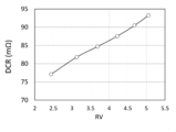
(結果1)図5に示されるように、直流抵抗成分DCRは、内部コア容積比RVに対して線形的に増加する。なお、直流抵抗成分DCRは、圧粉成形コア30を構成する材料によって変化しないため、図5には1系統のプロットのみが示されている。
(結果1)図5に示されるように、直流抵抗成分DCRは、内部コア容積比RVに対して線形的に増加する。なお、直流抵抗成分DCRは、圧粉成形コア30を構成する材料によって変化しないため、図5には1系統のプロットのみが示されている。
(結果2)図6に示されるように、自己インダクタンスLは、内部コア容積比RVが4.5程度の場合にピークを有する。圧粉成形コア30を構成する材料の影響により、全体的傾向として、計算例1の自己インダクタンスLは計算例2の自己インダクタンスLよりも高く、計算例2の自己インダクタンスLは計算例3の自己インダクタンスLよりも高い。
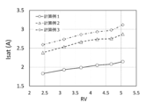
(結果3)図7に示されるように、Isat(直流重畳特性)は、内部コア容積比RVに対しておおむね線形的に増加するが直流抵抗成分DCRの場合よりも非線形性が認められる。圧粉成形コア30を構成する材料の影響により、全体的傾向として、計算例1のIsatは計算例2のIsatよりも低く、計算例2のIsatは計算例3のIsatよりも低い。
(結果4)図8に示されるように、総合評価としてのIsat×L/DCRは、内部コア容積比RVが増加するほど増加するが、RVが4程度をピークとする傾向がみられる。そして、内部コア容積比RVが5を超えると、Isat×L/DCRが低下する場合もあることが明らかになった。なお、図8では、Isat×L/DCRについて計算例1-6の結果を基準とする相対値を縦軸とした。図8から明らかなように、内部コア容積比RVを3以上5以下とすることにより、インダクタンス素子100の基本特性と直流重畳特性とを総合的に高めることができることが確認された。また、内部コア容積比RVが低い場合、具体的には3以下の場合には、圧粉成形コア30を構成する材料が総合評価としてのIsat×L/DCRに与える影響は小さいが、内部コア容積比RVが高い場合、具体的には3を超える場合には、圧粉成形コア30を構成する材料が総合評価としてのIsat×L/DCRに与える影響が大きくなることも確認された。なお、上記シミュレーションでは平角線も用いたエッジワイズ巻のコイルを用いて行ったが、同じく平角線を用いたα巻のコイルでも同様な結果が得られたことを確認した。
本発明の一実施形態に係る電子・電気機器は、上記の本発明の一実施形態に係るインダクタンス素子100が実装された電子・電気機器であって、コイル封入圧粉成形コア100Aが有するコイル10のそれぞれの端部(端子部20,25)に接続された接続端子(塗布型電極40,45)にて基板に接続されているものである。本発明の一実施形態に係る電子・電気機器は、本発明の一実施形態に係るインダクタンス素子100が実装されているため、機器の小型化も容易である。また、機器内に大電流を流したり、高周波を印加したりすることがあっても、インダクタンス素子100の機能低下や発熱に起因する不具合が生じにくい。
以上説明した実施形態は、本発明の理解を容易にするために記載されたものであって、本発明を限定するために記載されたものではない。したがって、上記実施形態に開示された各要素は、本発明の技術的範囲に属する全ての設計変更や均等物をも含む趣旨である。
本発明のコイル封入圧粉成形コアを備えるインダクタンス素子は、スマートフォンの表示部を駆動するための部品などとして好適に使用されうる。
100 :インダクタンス素子
100A :コイル封入圧粉成形コア
10 :コイル
10C :巻回体
20 :端子部
25 :端子部
30 :圧粉成形コア
31 :第1領域
32 :第2領域
33 :第3領域
40 :塗布型電極
40a :側面塗布部分
45 :塗布型電極
45a :側面塗布部分
100A :コイル封入圧粉成形コア
10 :コイル
10C :巻回体
20 :端子部
25 :端子部
30 :圧粉成形コア
31 :第1領域
32 :第2領域
33 :第3領域
40 :塗布型電極
40a :側面塗布部分
45 :塗布型電極
45a :側面塗布部分
Claims (9)
- 巻回体を有するコイルが磁性粉末を含む圧粉成形コアに封入されたコイル封入圧粉成形コアであって、下記に定義される内部コア容積比RVが3以上5以下であることを特徴とするコイル封入圧粉成形コア。
RV=(V1/V2)/(1-V/Vp)
ここで、V1は、前記圧粉成形コアにおける、前記コイルの巻回軸に沿った方向である第一方向から前記コイル封入圧粉成形コアをみたときに前記コイルの前記巻回体の内側に位置する領域の容積であり、V2は、前記圧粉成形コアにおける、前記第一方向から前記コイル封入圧粉成形コアをみたときに前記コイルの前記巻回体の外側に位置する領域の容積であり、Vは前記圧粉成形コアの容積であり、Vpは前記コイル封入圧粉成形コアの容積である。 - 前記磁性粉末は、少なくとも一部が非晶質磁性材料からなる、請求項1に記載のコイル封入圧粉成形コア。
- 前記磁性粉末は、前記非晶質磁性材料および結晶質磁性材料からなる、請求項2に記載のコイル封入圧粉成形コア。
- 前記結晶質磁性材料は、Fe-Si-Cr系合金、Fe-Ni系合金、Fe-Co系合金、Fe-V系合金、Fe-Al系合金、Fe-Si系合金、Fe-Si-Al系合金、カルボニル鉄および純鉄からなる群から選ばれた1種または2種以上の材料を含む、請求項3に記載のコイル封入圧粉成形コア。
- 前記結晶質磁性材料はFe-Si-Cr系合金からなる、請求項4に記載のコイル封入圧粉成形コア。
- 前記非晶質磁性材料は、Fe-Si-B系合金、Fe-P-C系合金およびCo-Fe-Si-B系合金からなる群から選ばれた1種または2種以上の材料を含む、請求項2から5のいずれか一項に記載のコイル封入圧粉成形コア。
- 前記非晶質磁性材料はFe-P-C系合金からなる、請求項6に記載のコイル封入圧粉成形コア。
- 請求項1から7のいずれかに記載されるコイル封入圧粉成形コアと当該コイル封入圧粉成形コアが有するコイルのそれぞれの端部に接続された接続端子とを備えるインダクタンス素子。
- 請求項8に記載されるインダクタンス素子が実装された電子・電気機器であって、前記インダクタンス素子は前記接続端子にて基板に接続されている電子・電気機器。
Priority Applications (3)
| Application Number | Priority Date | Filing Date | Title |
|---|---|---|---|
| JP2020525272A JP6986152B2 (ja) | 2018-06-15 | 2019-03-20 | コイル封入圧粉成形コア、インダクタンス素子、および電子・電気機器 |
| CN201980037307.XA CN112236835B (zh) | 2018-06-15 | 2019-03-20 | 线圈封入压粉成形芯、电感元件以及电子/电气设备 |
| US17/081,644 US12073978B2 (en) | 2018-06-15 | 2020-10-27 | Coil-embedded dust core, inductance element, and electric or electronic device |
Applications Claiming Priority (2)
| Application Number | Priority Date | Filing Date | Title |
|---|---|---|---|
| JP2018114527 | 2018-06-15 | ||
| JP2018-114527 | 2018-06-15 |
Related Child Applications (1)
| Application Number | Title | Priority Date | Filing Date |
|---|---|---|---|
| US17/081,644 Continuation US12073978B2 (en) | 2018-06-15 | 2020-10-27 | Coil-embedded dust core, inductance element, and electric or electronic device |
Publications (1)
| Publication Number | Publication Date |
|---|---|
| WO2019239671A1 true WO2019239671A1 (ja) | 2019-12-19 |
Family
ID=68841758
Family Applications (1)
| Application Number | Title | Priority Date | Filing Date |
|---|---|---|---|
| PCT/JP2019/011818 Ceased WO2019239671A1 (ja) | 2018-06-15 | 2019-03-20 | コイル封入圧粉成形コア、インダクタンス素子、および電子・電気機器 |
Country Status (4)
| Country | Link |
|---|---|
| US (1) | US12073978B2 (ja) |
| JP (1) | JP6986152B2 (ja) |
| CN (1) | CN112236835B (ja) |
| WO (1) | WO2019239671A1 (ja) |
Citations (6)
| Publication number | Priority date | Publication date | Assignee | Title |
|---|---|---|---|---|
| JP2010283379A (ja) * | 2010-08-19 | 2010-12-16 | Sumitomo Electric Ind Ltd | リアクトル |
| JP2011086952A (ja) * | 2010-12-21 | 2011-04-28 | Sumitomo Electric Ind Ltd | リアクトル用コア、リアクトル、及びリアクトルの製造方法 |
| JP2016122789A (ja) * | 2014-12-25 | 2016-07-07 | 岡山技研株式会社 | 磁気コアとそれを用いたインダクタ |
| WO2016185940A1 (ja) * | 2015-05-19 | 2016-11-24 | アルプス・グリーンデバイス株式会社 | 圧粉コア、当該圧粉コアの製造方法、該圧粉コアを備えるインダクタ、および該インダクタが実装された電子・電気機器 |
| JP2017108098A (ja) * | 2015-11-26 | 2017-06-15 | アルプス電気株式会社 | 圧粉コア、当該圧粉コアの製造方法、該圧粉コアを備えるインダクタ、および該インダクタが実装された電子・電気機器 |
| JP2018092979A (ja) * | 2016-11-30 | 2018-06-14 | 新日鐵住金株式会社 | 変圧器、変圧器用の板状鉄心及び変圧器用の板状鉄心の製造方法 |
Family Cites Families (20)
| Publication number | Priority date | Publication date | Assignee | Title |
|---|---|---|---|---|
| JP2002324714A (ja) * | 2001-02-21 | 2002-11-08 | Tdk Corp | コイル封入圧粉磁芯およびその製造方法 |
| JP2003282342A (ja) | 2002-03-26 | 2003-10-03 | Tdk Corp | コイル封入圧粉磁芯 |
| CN100550570C (zh) * | 2002-05-13 | 2009-10-14 | 捷通国际有限公司 | 电能传输系统和在其中使用的初级装置 |
| JP2005005287A (ja) * | 2003-06-09 | 2005-01-06 | Matsushita Electric Ind Co Ltd | インダクタンス部品とそれを用いた電子機器 |
| JP2006032907A (ja) * | 2004-05-17 | 2006-02-02 | Nec Tokin Corp | 高周波用磁心及びそれを用いたインダクタンス部品 |
| JP4849545B2 (ja) * | 2006-02-02 | 2012-01-11 | Necトーキン株式会社 | 非晶質軟磁性合金、非晶質軟磁性合金部材、非晶質軟磁性合金薄帯、非晶質軟磁性合金粉末、及びそれを用いた磁芯ならびにインダクタンス部品 |
| JP6168378B2 (ja) | 2011-05-09 | 2017-07-26 | 株式会社トーキン | 線輪部品 |
| CN102915826B (zh) * | 2011-08-04 | 2015-02-04 | 阿尔卑斯绿色器件株式会社 | 电感器及其制造方法 |
| JP2013179259A (ja) * | 2012-02-08 | 2013-09-09 | Sumitomo Electric Ind Ltd | リアクトル、コンバータ及び電力変換装置、並びにリアクトル用コア材料 |
| US8723629B1 (en) * | 2013-01-10 | 2014-05-13 | Cyntec Co., Ltd. | Magnetic device with high saturation current and low core loss |
| JP6060116B2 (ja) * | 2014-07-18 | 2017-01-11 | 東光株式会社 | 表面実装インダクタ及びその製造方法 |
| JP6345146B2 (ja) * | 2015-03-31 | 2018-06-20 | 太陽誘電株式会社 | コイル部品 |
| JP6477429B2 (ja) * | 2015-11-09 | 2019-03-06 | 株式会社村田製作所 | コイル部品 |
| KR101883043B1 (ko) * | 2016-02-19 | 2018-07-27 | 삼성전기주식회사 | 코일 부품 |
| US10283266B2 (en) | 2016-04-25 | 2019-05-07 | Alps Alpine Co., Ltd. | Powder core, manufacturing method of powder core, inductor including powder core, and electronic/electric device having inductor mounted therein |
| JP2018056524A (ja) * | 2016-09-30 | 2018-04-05 | Tdk株式会社 | コイル部品 |
| JP6648688B2 (ja) * | 2016-12-27 | 2020-02-14 | 株式会社村田製作所 | 電子部品 |
| JP6575537B2 (ja) * | 2017-01-10 | 2019-09-18 | 株式会社村田製作所 | インダクタ部品 |
| JP7021459B2 (ja) * | 2017-05-02 | 2022-02-17 | Tdk株式会社 | インダクタ素子 |
| JP3213895U (ja) * | 2017-09-26 | 2017-12-07 | アルプス電気株式会社 | チップインダクタ |
-
2019
- 2019-03-20 JP JP2020525272A patent/JP6986152B2/ja active Active
- 2019-03-20 CN CN201980037307.XA patent/CN112236835B/zh active Active
- 2019-03-20 WO PCT/JP2019/011818 patent/WO2019239671A1/ja not_active Ceased
-
2020
- 2020-10-27 US US17/081,644 patent/US12073978B2/en active Active
Patent Citations (6)
| Publication number | Priority date | Publication date | Assignee | Title |
|---|---|---|---|---|
| JP2010283379A (ja) * | 2010-08-19 | 2010-12-16 | Sumitomo Electric Ind Ltd | リアクトル |
| JP2011086952A (ja) * | 2010-12-21 | 2011-04-28 | Sumitomo Electric Ind Ltd | リアクトル用コア、リアクトル、及びリアクトルの製造方法 |
| JP2016122789A (ja) * | 2014-12-25 | 2016-07-07 | 岡山技研株式会社 | 磁気コアとそれを用いたインダクタ |
| WO2016185940A1 (ja) * | 2015-05-19 | 2016-11-24 | アルプス・グリーンデバイス株式会社 | 圧粉コア、当該圧粉コアの製造方法、該圧粉コアを備えるインダクタ、および該インダクタが実装された電子・電気機器 |
| JP2017108098A (ja) * | 2015-11-26 | 2017-06-15 | アルプス電気株式会社 | 圧粉コア、当該圧粉コアの製造方法、該圧粉コアを備えるインダクタ、および該インダクタが実装された電子・電気機器 |
| JP2018092979A (ja) * | 2016-11-30 | 2018-06-14 | 新日鐵住金株式会社 | 変圧器、変圧器用の板状鉄心及び変圧器用の板状鉄心の製造方法 |
Also Published As
| Publication number | Publication date |
|---|---|
| CN112236835B (zh) | 2022-06-28 |
| US20210074464A1 (en) | 2021-03-11 |
| US12073978B2 (en) | 2024-08-27 |
| CN112236835A (zh) | 2021-01-15 |
| JPWO2019239671A1 (ja) | 2021-05-13 |
| JP6986152B2 (ja) | 2021-12-22 |
Similar Documents
| Publication | Publication Date | Title |
|---|---|---|
| JP6513458B2 (ja) | 圧粉コア、該圧粉コアの製造方法、該圧粉コアを備える電子・電気部品、および該電子・電気部品が実装された電子・電気機器 | |
| WO2016185940A1 (ja) | 圧粉コア、当該圧粉コアの製造方法、該圧粉コアを備えるインダクタ、および該インダクタが実装された電子・電気機器 | |
| WO2017038295A1 (ja) | 圧粉コア、該圧粉コアの製造方法、該圧粉コアを備える電気・電子部品、および該電気・電子部品が実装された電気・電子機器 | |
| JP2017108098A (ja) | 圧粉コア、当該圧粉コアの製造方法、該圧粉コアを備えるインダクタ、および該インダクタが実装された電子・電気機器 | |
| US10283266B2 (en) | Powder core, manufacturing method of powder core, inductor including powder core, and electronic/electric device having inductor mounted therein | |
| CN105304259B (zh) | 压粉磁芯及其制造方法、电子电气部件及电子电气设备 | |
| KR102104701B1 (ko) | 압분 코어, 당해 압분 코어의 제조 방법, 그 압분 코어를 구비하는 인덕터, 및 그 인덕터가 실장된 전자·전기 기기 | |
| JP2004197218A (ja) | 複合磁性材料とそれを用いたコア及び磁性素子 | |
| CN213958731U (zh) | 混合芯、电抗器以及电气/电子设备 | |
| WO2018207521A1 (ja) | 圧粉コア、当該圧粉コアの製造方法、該圧粉コアを備えるインダクタ、および該インダクタが実装された電子・電気機器 | |
| JP6986152B2 (ja) | コイル封入圧粉成形コア、インダクタンス素子、および電子・電気機器 | |
| US12224092B2 (en) | Compression molded core, method for manufacturing the compression molded core, inductor including the compression molded core, and electric/electronic equipment mounted with the inductor | |
| WO2011121947A1 (ja) | 複合磁性材料とそれを用いたコイル埋設型磁性素子およびその製造方法 | |
| JP6035490B2 (ja) | 圧粉コア、電気・電子部品および電気・電子機器 | |
| JP6093941B2 (ja) | 圧粉コア、電気・電子部品および電気・電子機器 | |
| JP3230120U (ja) | ハイブリッドコア、リアクトルおよび電気・電子機器 | |
| US20240282492A1 (en) | Dust core, inductor, and electronic/electric device | |
| JP6944313B2 (ja) | 磁性粉末、圧粉コア、インダクタ、および電子・電気機器 | |
| JP2024118236A (ja) | インダクタ、および電子・電気機器 | |
| WO2018154988A1 (ja) | 降圧回路、及び降圧コンバータ | |
| WO2025009205A1 (ja) | 磁性部品および電気・電子機器 |
Legal Events
| Date | Code | Title | Description |
|---|---|---|---|
| 121 | Ep: the epo has been informed by wipo that ep was designated in this application |
Ref document number: 19820381 Country of ref document: EP Kind code of ref document: A1 |
|
| ENP | Entry into the national phase |
Ref document number: 2020525272 Country of ref document: JP Kind code of ref document: A |
|
| NENP | Non-entry into the national phase |
Ref country code: DE |
|
| 122 | Ep: pct application non-entry in european phase |
Ref document number: 19820381 Country of ref document: EP Kind code of ref document: A1 |