WO2019235477A1 - 収容ユニットの取付け構造 - Google Patents
収容ユニットの取付け構造 Download PDFInfo
- Publication number
- WO2019235477A1 WO2019235477A1 PCT/JP2019/022177 JP2019022177W WO2019235477A1 WO 2019235477 A1 WO2019235477 A1 WO 2019235477A1 JP 2019022177 W JP2019022177 W JP 2019022177W WO 2019235477 A1 WO2019235477 A1 WO 2019235477A1
- Authority
- WO
- WIPO (PCT)
- Prior art keywords
- lid
- case
- mounting
- width direction
- vehicle width
- Prior art date
- Legal status (The legal status is an assumption and is not a legal conclusion. Google has not performed a legal analysis and makes no representation as to the accuracy of the status listed.)
- Ceased
Links
Images

Classifications
-
- B—PERFORMING OPERATIONS; TRANSPORTING
- B60—VEHICLES IN GENERAL
- B60R—VEHICLES, VEHICLE FITTINGS, OR VEHICLE PARTS, NOT OTHERWISE PROVIDED FOR
- B60R21/00—Arrangements or fittings on vehicles for protecting or preventing injuries to occupants or pedestrians in case of accidents or other traffic risks
- B60R21/02—Occupant safety arrangements or fittings, e.g. crash pads
- B60R21/16—Inflatable occupant restraints or confinements designed to inflate upon impact or impending impact, e.g. air bags
- B60R21/20—Arrangements for storing inflatable members in their non-use or deflated condition; Arrangement or mounting of air bag modules or components
- B60R21/205—Arrangements for storing inflatable members in their non-use or deflated condition; Arrangement or mounting of air bag modules or components in dashboards
- B60R21/206—Arrangements for storing inflatable members in their non-use or deflated condition; Arrangement or mounting of air bag modules or components in dashboards in the lower part of dashboards, e.g. for protecting the knees
Definitions
- This disclosure relates to a mounting structure for a storage unit that stores an airbag.
- an airbag as a passenger safety device is mounted in the passenger compartment.
- a knee airbag for protecting an occupant's knee is stored in a storage unit in a folded state, and the storage unit is mounted on a mounting portion (instrument panel or cross member) of a passenger compartment. It is fixed.
- the above-mentioned accommodation unit has, for example, a case and a lid arranged so as to sandwich an airbag, and the case and the lid are engaged with each other so as to be displaceable.
- the storage unit is mounted on the mounting portion, it is desirable to attach the case and the lid, but the case and the lid are displaced, so that the mounting operation of the storage unit becomes worse.
- the present disclosure has been made in view of these points, and an object thereof is to improve the attachment property of a storage unit in which a case and a lid are movably engaged with each other.
- a housing unit that includes a case and a lid that are displaceably engaged with each other, and that houses an airbag between the case and the lid.
- a housing unit that is detachably mounted on a mounting portion arranged along the mounting portion, an extension portion that extends in the mounting direction from both sides of the case in the vehicle width direction, and is provided in the mounting portion, A guide support portion that guides the extension portion when the housing unit is mounted, and supports the extension portion; and an attachment portion having locking holes formed on both sides of the mounting portion in the vehicle width direction;
- a housing unit mounting structure provided with fixing portions that are provided on both sides of the lid in the vehicle width direction and are locked and fixed to the locking holes.
- the lid may cover the case, and the extending portion may extend from the case so as to be exposed from the lid.
- the guide support part may have an insertion hole part through which the extension part is inserted.
- the fixing portion is fixed to the mounting portion by being locked in the locking hole and locked in the locking hole, and a first protrusion that positions the lid with respect to the mounting portion.
- a second protrusion may be included.
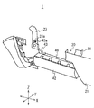
- Drawing 1 is a mimetic diagram for explaining attachment structure of storage unit 10 concerning one embodiment.
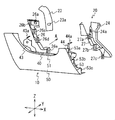
- FIG. 2 is a schematic diagram for explaining a state in which the lid 50 of the storage unit 10 of FIG. 1 is removed.
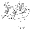
- FIG. 3 is a schematic diagram for explaining a state when the accommodation unit 10 is attached.
- FIG. 4 is a schematic diagram for explaining a state when the accommodation unit 10 is attached.
- FIGS. 1 and 2 An accommodation unit mounting structure according to an embodiment of the present disclosure will be described with reference to FIGS. 1 and 2. In the following, description will be given by taking as an example a mounting structure of a housing unit mounted on a vehicle.
- FIG. 1 is a mimetic diagram for explaining attachment structure of storage unit 10 concerning one embodiment.
- FIG. 2 is a schematic diagram for explaining a state in which the lid 50 of the storage unit 10 of FIG. 1 is removed.
- the vehicle 1 is a large vehicle such as a truck.
- a housing unit 10 is attached to a front portion of a cab that is a passenger compartment.
- the vehicle 1 includes a storage unit 10 and a mounting portion 20.
- the accommodating unit 10 accommodates an airbag.
- the accommodation unit 10 accommodates a folded airbag.
- the accommodation unit 10 accommodates a knee airbag for protecting the passenger's knee.
- the housing unit 10 includes a case 40 and a lid 50 that accommodates an air bag therebetween, and the lid 50 covers the case 40.
- the lid 50 is located at a position facing the occupant's knee, and the case 40 is located on the back side.
- the case 40 and the lid 50 are engaged with each other by an engaging means so as to be displaceable.
- the upper and lower portions of the case 40 are engaged with the lid 50 via hooks.
- the mounting portion 20 is a portion where the housing unit 10 is detachably mounted, and is disposed in the vehicle interior along the vehicle width direction (X direction in FIG. 1).
- the mounting unit 20 includes, for example, an instrument panel 21 and a cross member (not shown).
- the instrument panel 21 is a resin panel on which meters are arranged, for example.
- the cross member is a part that forms the frame of the passenger compartment, and various parts are fixed thereto.
- the case 40 and the lid 50 are displaceably engaged, it is difficult to position the storage unit 10 when mounting the storage unit 10 to the mounting portion 20. In particular, since it is difficult to confirm the position of the case 40 hidden by the lid 50, it is difficult to position the case 40.
- the case 40 is first guided and positioned with respect to the mounting unit 20, and then the lid 50 is attached to the mounting unit 20. By fixing, the attachment property of the storage unit 10 is improved.
- 3 and 4 are schematic views for explaining a state when the accommodation unit 10 is attached. 3 and 4, most of the instrument panel 21 in FIG. 1 is omitted for convenience of explanation.
- the case 40 is made of metal here. As shown in FIGS. 2 to 4, the case 40 includes a main body 42 and brackets 43 and 44.
- the main body 42 is disposed along the vehicle width direction.
- the brackets 43 and 44 are respectively attached to both sides of the main body portion 42 in the longitudinal direction. As shown in FIG. 2, the brackets 43 and 44 are attached so as to be positioned above the main body 42. The upper portions of the brackets 43 and 44 are located closer to the lid 50 than the portion where the bracket 43 is attached to the main body portion 42.
- projecting piece portions 43a and 44a each having a projecting piece are provided at the upper ends of the brackets 43 and 44, respectively.
- the projecting piece portions 43 a and 44 a have an elongated shape and are extended portions that extend in the mounting direction of the storage unit 10.
- the projecting pieces 43 a and 44 a are provided at positions exposed from the lid 50 covering the case 40 (positions corresponding to the concave portions 51 of the lid 50).
- the projecting piece portions 43 a and 44 a are supported by the guide support portions 23 and 24 of the mounting portion 20.
- the guide support portions 23 and 24 are made of metal, for example, a bracket coupled to a cross member.
- the guide support portion 23 has an insertion hole portion 23a through which the projecting piece portion 43a is inserted, and the insertion hole portion 23a supports the guide support portion 23 as shown in FIG.
- the guide support portion 24 has an insertion hole portion 24 a through which the protruding piece portion 44 a is inserted, and the insertion hole portion 24 a supports the guide support portion 24.
- the guide support portions 23 and 24 are inserted into the insertion holes 23a and 24a through the projecting pieces 43a and 44a. (Specifically, it has a function of guiding the case 40). Thereby, the case 40 can be positioned at a desired position.
- the lid 50 is made of resin here.
- the lid 50 has fixing portions 52 and 53 that are fixed to the mounting portion 20 on both sides in the longitudinal direction (X direction).
- the fixing part 52 is located on one end side in the longitudinal direction, and the fixing part 53 is located on the other end side in the longitudinal direction.
- the fixing portions 52 and 53 are locked and fixed to attachment portions 26 and 27 formed on both sides of the mounting portion 20 in the vehicle width direction.
- the fixing part 52 has a plurality of locking projections 52a to 52e as shown in FIG.
- the locking projection 52a is locked with the locking hole 26a of the mounting portion 26, thereby positioning the lid 50 in the vehicle width direction.
- the locking protrusions 52b to 52e are arranged in the short direction of the lid 50, and are locked to the locking holes 26b to 26e of the mounting portion 20 to fix one end side of the lid 50 to the mounting portion 20. At the tips of the locking projections 52a to 52e, hook portions that are hooked into the locking holes 26a to 26e are formed.
- the fixing portion 53 has a plurality of locking protrusions 53a to 53c as shown in FIG.
- the locking protrusions 53a to 53c are arranged in the short direction of the lid 50, and the other end side of the lid 50 is fixed to the mounting portion 20 by locking with the locking holes 27a to 27c of the mounting portion 27. .
- hook portions that are hooked in the locking holes 27a to 27c are formed, respectively.
- the locking protrusion 52a corresponds to the first protrusion
- the locking protrusions 52b to 52e and 53a to 53c correspond to the second protrusion.
- the accommodation unit 10 in which an airbag is accommodated between the case 40 and the lid 50 is prepared.
- the case 40 and the lid 50 are engaged with each other so as to be displaceable.
- the protruding pieces 43a and 44a of the case 40 are inserted through the insertion holes 23a and 24a of the guide support portions 23 and 24.
- the case 40 is guided.
- the operator can check the projecting pieces 43 a and 44 a and the insertion holes 23 a and 24 a through the recess 51 of the lid 50.
- the case 40 is positioned by the protrusions 43a and 44a being supported by the insertion holes 23a and 24a.
- the fixing portions 52 and 53 of the lid 50 are not in contact with the mounting portion 20.
- the housing unit 10 is further moved in the mounting direction A with the case 40 positioned, and the locking protrusion 52a of the lid 50 is locked in the locking hole 26a. Thereby, the left-right direction of the lid
- cover 50 is positioned. Thereafter, the locking protrusions 52b to 52e of the lid 50 are locked to the locking holes 26b to 26e, and the locking protrusions 53a to 53c are locked to the locking holes 27a to 27c, so that the lid 50 is attached to the mounting portion 20. It is fixed to the attachment portions 26 and 27. Thereby, the accommodation unit 10 is attached to the mounting portion 20.
- the housing unit 10 in which the case 40 and the lid 50 are engaged with each other so as to be displaceable extends from the case 40 in the mounting direction A and is supported by the guide support portions 23 and 24. , 44a, and fixing portions 52, 53 that are locked and fixed in the locking holes 26a to 26e, 27a to 27c.
- the present disclosure is effective in improving the mounting work of the housing unit by providing an effect of improving the mounting property of the housing unit in which the case and the lid are displaceably engaged with each other.
Landscapes
- Engineering & Computer Science (AREA)
- Mechanical Engineering (AREA)
- Air Bags (AREA)
Abstract
車両1は、互いに変位可能に係合しているケース40及び蓋50を有し、ケース40と蓋50の間にエアバックを収容する収容ユニット10であって、車室内に車幅方向に沿って配置された装着部20に着脱可能に装着されている収容ユニット10と、ケース40の車幅方向の両側から装着方向へ延出している突片部43a、44aと、装着部20に設けられ、収容ユニット10の装着時に突片部43a、44aをガイドすると共に、突片部43a、44aを支持しているガイド支持部23、24と、装着部20の車幅方向の両側に係止穴26a~26e、27a~27cが形成された取付け部26、27と、蓋50の車幅方向の両側に設けられており、係止穴の各々に係止して固定されている固定部52、53とを備える。
Description
本開示は、エアバックを収容する収容ユニットの取付け構造に関する。
車両においては、乗員の安全装置としてのエアバックが、車室に搭載されている。例えば、乗員の膝部を保護するためのニーエアバッグが、折り畳まれた状態で収容ユニットに収容されており、収容ユニットは、車室の装着部(インストルメントパネルやクロスメンバー)に装着されて固定されている。
上記の収容ユニットは、例えばエアバックを挟むように配置されたケース及び蓋を有しており、ケース及び蓋が互いに変位可能に係合している。収容ユニットを装着部に装着する際にはケースと蓋をそれぞれ取り付けることが望ましいが、ケースと蓋が変位するため、収容ユニットの取付け作業が悪くなってしまう。
そこで、本開示はこれらの点に鑑みてなされたものであり、ケースと蓋が互いに変位可能に係合した収容ユニットの取付け性を向上させることを目的とする。
本開示の一の態様においては、互いに変位可能に係合しているケース及び蓋を有し、前記ケースと前記蓋の間にエアバックを収容する収容ユニットであって、車室内に車幅方向に沿って配置された装着部に着脱可能に装着されている収容ユニットと、前記ケースの前記車幅方向の両側から装着方向へ延出している延出部と、前記装着部に設けられ、前記収容ユニットの装着時に前記延出部をガイドすると共に、前記延出部を支持しているガイド支持部と、前記装着部の前記車幅方向の両側に係止穴が形成された取付け部と、前記蓋の前記車幅方向の両側に設けられており、前記係止穴の各々に係止して固定されている固定部とを備える、収容ユニットの取付け構造を提供する。
また、前記蓋は、前記ケースを覆っており、前記延出部は、前記蓋から露出するように前記ケースから延出していることとしてもよい。
また、前記ガイド支持部は、前記延出部が挿通している挿通穴部を有することとしてもよい。
また、前記固定部は、前記係止穴に係止して前記装着部に対する前記蓋の位置決めを行っている第1突起と、前記係止穴に係止して前記装着部に固定されている第2突起と、を含むこととしてもよい。
本開示によれば、ケースと蓋が互いに変位可能に係合した収容ユニットの取付け性を向上できるという効果を奏する。
<収容ユニットの取付け構造>
本開示の一の実施形態に係る収容ユニットの取付け構造について、図1及び図2を参照しながら説明する。以下では、車両に搭載された収容ユニットの取付け構造を例に挙げて、説明する。
本開示の一の実施形態に係る収容ユニットの取付け構造について、図1及び図2を参照しながら説明する。以下では、車両に搭載された収容ユニットの取付け構造を例に挙げて、説明する。
図1は、一の実施形態に係る収容ユニット10の取付け構造を説明するための模式図である。図2は、図1の収容ユニット10の蓋50を取り除いた状態を説明するための模式図である。
車両1は、例えばトラック等の大型車両である。車両1においては、車室であるキャブの前部に、収容ユニット10が取付けられている。車両1は、図1に示すように、収容ユニット10と、装着部20とを有する。
車両1は、例えばトラック等の大型車両である。車両1においては、車室であるキャブの前部に、収容ユニット10が取付けられている。車両1は、図1に示すように、収容ユニット10と、装着部20とを有する。
収容ユニット10は、エアバックを収容している。収容ユニット10には、折り畳まれた状態のエアバックが収容されている。収容ユニット10は、ここでは、乗員の膝部を保護するためのニーエアバッグを収容している。収容ユニット10は、間にエアバックを収容しているケース40と蓋50を有しており、蓋50がケース40を覆っている。蓋50が乗員の膝部に対面する位置に位置し、ケース40が奥側に位置している。
ケース40及び蓋50は、互いに変位可能に係合手段によって係合している。例えば、ケース40の上部及び下部が、フックを介して蓋50と係合している。収容ユニット10が装着部20に取り付けられていない際には、ケース40及び蓋50は互いに相対移動可能な状態となっている。
装着部20は、収容ユニット10が着脱可能に装着される部分であり、車室内に車幅方向(図1のX方向)に沿って配置されている。装着部20は、例えばインストルメントパネル21とクロスメンバー(不図示)で構成される。インストルメントパネル21は、例えばメーター類が配置されている樹脂製のパネルである。クロスメンバーは、車室の骨格を成す部品であり、様々な部品が固定されている。
前述したようにケース40及び蓋50が変位可能に係合している場合には、収容ユニット10を装着部20に装着する際に、収容ユニット10の位置決めが行い難い。特に、蓋50で隠れているケース40の位置を確認し難いため、ケース40の位置決めを行い難い。
これに対して、本実施形態では、詳細は後述するが、収容ユニット10を装着する際に、ケース40を先にガイドさせて装着部20に対して位置決めした後に、蓋50を装着部20に固定させることで、収容ユニット10の取付け性が向上している。
これに対して、本実施形態では、詳細は後述するが、収容ユニット10を装着する際に、ケース40を先にガイドさせて装着部20に対して位置決めした後に、蓋50を装着部20に固定させることで、収容ユニット10の取付け性が向上している。
以下では、収容ユニット10(ケース40及び蓋50)の装着部20への取付け構造の詳細について、図1~図4を参照しながら説明する。以下では、取付け構造に関連するケース40、蓋50及び装着部20の構成について説明する。
図3及び図4は、収容ユニット10を取付ける際の状態を説明するための模式図である。なお、図3及び図4では、説明の便宜上、図1のインストルメントパネル21の大部分が省略されている。
ケース40は、ここでは金属製である。ケース40は、図2~図4に示すように、本体部42と、ブラケット43、44とを有する。
ケース40は、ここでは金属製である。ケース40は、図2~図4に示すように、本体部42と、ブラケット43、44とを有する。
本体部42は、図2に示すように、車幅方向に沿って配置されている。
ブラケット43、44は、本体部42の長手方向の両側にそれぞれ取り付けられている。ブラケット43、44は、図2に示すように、本体部42の上方に位置するように取り付けられている。ブラケット43、44の上部は、ブラケット43が本体部42に取り付けられる部分よりも蓋50側に位置している。
ブラケット43、44は、本体部42の長手方向の両側にそれぞれ取り付けられている。ブラケット43、44は、図2に示すように、本体部42の上方に位置するように取り付けられている。ブラケット43、44の上部は、ブラケット43が本体部42に取り付けられる部分よりも蓋50側に位置している。
ブラケット43、44の上部先端には、図3及び図4に示すように、それぞれ突片が形成された突片部43a、44aが設けられている。突片部43a、44aは、細長い形状を成しており、収容ユニット10の装着方向へ延出している延出部である。突片部43a、44aは、ケース40を覆う蓋50から露出する位置(蓋50の凹部51に対応する位置)に設けられている。
突片部43a、44aは、装着部20のガイド支持部23、24に支持されている。ガイド支持部23、24は、ここでは金属製であり、例えばクロスメンバーに結合されているブラケットである。ガイド支持部23は、突片部43aが挿通している挿通穴部23aを有し、図1に示すように挿通穴部23aがガイド支持部23を支持している。同様に、ガイド支持部24は、突片部44aが挿通している挿通穴部24aを有し、挿通穴部24aがガイド支持部24を支持している。
ガイド支持部23、24は、収容ユニット10が装着方向A(図3)に装着される際に、挿通穴部23a、24aに対して突片部43a、44aが挿通することで、収容ユニット10(具体的にはケース40)をガイドする機能を有する。これにより、ケース40を所望の位置に位置決めすることが可能となる。
蓋50は、ここでは樹脂製である。蓋50は、長手方向(X方向)の両側に、装着部20に固定される固定部52、53を有する。固定部52は、長手方向の一端側に位置し、固定部53は、長手方向の他端側に位置している。固定部52、53は、装着部20の車幅方向の両側に形成された取付け部26、27に係止して固定される。
固定部52は、図4に示すように、複数の係止突起52a~52eを有する。係止突起52aは、取付け部26の係止穴26aと係止することで、蓋50の車幅方向の位置決めを行う。係止突起52b~52eは、蓋50の短手方向に配置されており、装着部20の係止穴26b~26eと係止することで、蓋50の一端側を装着部20に固定させる。係止突起52a~52eの先端には、それぞれ係止穴26a~26eに引っ掛かる引っ掛け部が形成されている。
固定部53は、図3に示すように、複数の係止突起53a~53cを有する。係止突起53a~53cは、蓋50の短手方向に配置されており、取付け部27の係止穴27a~27cと係止することで、蓋50の他端側を装着部20に固定させる。係止突起53a~53cの先端には、それぞれ係止穴27a~27cに引っ掛かる引っ掛け部が形成されている。なお、本実施形態では、係止突起52aが第1突起に該当し、係止突起52b~52e、53a~53cが第2突起に該当する。
上述した収容ユニット10の装着部20への取付け作業の流れについて説明する。
まず、ケース40と蓋50の間にエアバッグが収容された収容ユニット10を準備する。ケース40と蓋50は、互いに変位可能に係合している。
まず、ケース40と蓋50の間にエアバッグが収容された収容ユニット10を準備する。ケース40と蓋50は、互いに変位可能に係合している。
次に、収容ユニット10を装着方向Aへ装着させる際に(図3参照)、ケース40の突片部43a、44aを、ガイド支持部23、24の挿通穴部23a、24aに挿通させることで、ケース40をガイドさせる。この際、作業者は、蓋50の凹部51を通して突片部43a、44a及び挿通穴部23a、24aを確認できる。その後、突片部43a、44aが挿通穴部23a、24aによって支持されることで、ケース40が位置決めされる。この際、蓋50の固定部52、53は、装着部20に接触していない。
次に、ケース40が位置決めされた状態で収容ユニット10を装着方向Aへ更に移動させて、蓋50の係止突起52aを係止穴26aに係止させる。これにより、蓋50の左右方向が位置決めされる。その後、蓋50の係止突起52b~52eを係止穴26b~26eに係止させ、係止突起53a~53cを係止穴27a~27cに係止させることで、蓋50が装着部20の取付け部26、27に固定される。これにより、収容ユニット10が装着部20に取り付けられる。
<本実施形態における効果>
上述した実施形態では、ケース40と蓋50が互いに変位可能に係合された収容ユニット10は、ケース40から装着方向Aへ延出しておりガイド支持部23、24に支持される突片部43a、44aと、係止穴26a~26e、27a~27cに係止されて固定される固定部52、53とを有する。
これにより、収容ユニット10を装着部20へ装着する際に、まずケース40の突片部43a、44aをガイド支持部23、24によってガイドされることで、ケース40が位置決めされる。その後、ケース40が位置決めされた状態で、蓋50が固定部52、53を介して装着部20に固定される。これにより、収容ユニット10のケース40及び蓋50が互いに変位可能な構成であっても、収容ユニット10を装着部20に取り付けやすくなる。
上述した実施形態では、ケース40と蓋50が互いに変位可能に係合された収容ユニット10は、ケース40から装着方向Aへ延出しておりガイド支持部23、24に支持される突片部43a、44aと、係止穴26a~26e、27a~27cに係止されて固定される固定部52、53とを有する。
これにより、収容ユニット10を装着部20へ装着する際に、まずケース40の突片部43a、44aをガイド支持部23、24によってガイドされることで、ケース40が位置決めされる。その後、ケース40が位置決めされた状態で、蓋50が固定部52、53を介して装着部20に固定される。これにより、収容ユニット10のケース40及び蓋50が互いに変位可能な構成であっても、収容ユニット10を装着部20に取り付けやすくなる。
以上、本発明を実施の形態を用いて説明したが、本発明の技術的範囲は上記実施の形態に記載の範囲には限定されず、その要旨の範囲内で種々の変形及び変更が可能である。例えば、装置の分散・統合の具体的な実施の形態は、以上の実施の形態に限られず、その全部又は一部について、任意の単位で機能的又は物理的に分散・統合して構成することができる。また、複数の実施の形態の任意の組み合わせによって生じる新たな実施の形態も、本発明の実施の形態に含まれる。組み合わせによって生じる新たな実施の形態の効果は、もとの実施の形態の効果を合わせ持つ。
本出願は、2018年06月05日付で出願された日本国特許出願(特願2018-108096)に基づくものであり、その内容はここに参照として取り込まれる。
本開示によれば、ケースと蓋が互いに変位可能に係合した収容ユニットの取付け性を向上することできる効果を奏し、収容ユニットの取付け作業を改善する点で有用である。
1 車両
10 収容ユニット
20 装着部
23、24 ガイド支持部
23a、24a 挿通穴部
26、27 取付け部
26a~26e、27a~27c 係止穴
40 ケース
43a、44a 突片部
50 蓋
52、53 固定部
52a~52e、53a~53c 係止突起
10 収容ユニット
20 装着部
23、24 ガイド支持部
23a、24a 挿通穴部
26、27 取付け部
26a~26e、27a~27c 係止穴
40 ケース
43a、44a 突片部
50 蓋
52、53 固定部
52a~52e、53a~53c 係止突起
Claims (4)
- 互いに変位可能に係合しているケース及び蓋を有し、前記ケースと前記蓋の間にエアバックを収容する収容ユニットであって、車室内に車幅方向に沿って配置された装着部に着脱可能に装着されている収容ユニットと、
前記ケースの前記車幅方向の両側から装着方向へ延出している延出部と、
前記装着部に設けられ、前記収容ユニットの装着時に前記延出部をガイドすると共に、前記延出部を支持しているガイド支持部と、
前記装着部の前記車幅方向の両側に係止穴が形成された取付け部と、
前記蓋の前記車幅方向の両側に設けられており、前記係止穴の各々に係止して固定されている固定部と、
を備える、収容ユニットの取付け構造。 - 前記蓋は、前記ケースを覆っており、
前記延出部は、前記蓋から露出するように前記ケースから延出している、
請求項1に記載の収容ユニットの取付け構造。 - 前記ガイド支持部は、前記延出部が挿通している挿通穴部を有する、
請求項1又は2に記載の収容ユニットの取付け構造。 - 前記固定部は、
前記係止穴に係止して前記装着部に対する前記蓋の位置決めを行っている第1突起と、
前記係止穴に係止して前記装着部に固定されている第2突起と、を含む、
請求項1から3のいずれか1項に記載の収容ユニットの取付け構造。
Priority Applications (1)
| Application Number | Priority Date | Filing Date | Title |
|---|---|---|---|
| CN201980038002.0A CN112236336B (zh) | 2018-06-05 | 2019-06-04 | 容纳单元的安装构造 |
Applications Claiming Priority (2)
| Application Number | Priority Date | Filing Date | Title |
|---|---|---|---|
| JP2018-108096 | 2018-06-05 | ||
| JP2018108096A JP7131094B2 (ja) | 2018-06-05 | 2018-06-05 | 収容ユニットの取付け構造 |
Publications (1)
| Publication Number | Publication Date |
|---|---|
| WO2019235477A1 true WO2019235477A1 (ja) | 2019-12-12 |
Family
ID=68769315
Family Applications (1)
| Application Number | Title | Priority Date | Filing Date |
|---|---|---|---|
| PCT/JP2019/022177 Ceased WO2019235477A1 (ja) | 2018-06-05 | 2019-06-04 | 収容ユニットの取付け構造 |
Country Status (3)
| Country | Link |
|---|---|
| JP (1) | JP7131094B2 (ja) |
| CN (1) | CN112236336B (ja) |
| WO (1) | WO2019235477A1 (ja) |
Cited By (1)
| Publication number | Priority date | Publication date | Assignee | Title |
|---|---|---|---|---|
| US20230182672A1 (en) * | 2021-12-15 | 2023-06-15 | Honda Motor Co., Ltd. | Instrument panel structure with knee airbag |
Citations (4)
| Publication number | Priority date | Publication date | Assignee | Title |
|---|---|---|---|---|
| JPH10310013A (ja) * | 1997-05-09 | 1998-11-24 | Kansei Corp | エアバッグ装置の取付構造 |
| JP2003182504A (ja) * | 2001-12-25 | 2003-07-03 | Toyoda Gosei Co Ltd | 膝保護用エアバッグ装置 |
| JP2004276682A (ja) * | 2003-03-13 | 2004-10-07 | Toyoda Gosei Co Ltd | 膝保護用エアバッグ装置 |
| KR100859287B1 (ko) * | 2007-10-30 | 2008-09-19 | 쌍용자동차 주식회사 | 자동차의 에어백 일체형 글로브박스 |
Family Cites Families (6)
| Publication number | Priority date | Publication date | Assignee | Title |
|---|---|---|---|---|
| JP3688066B2 (ja) * | 1996-08-21 | 2005-08-24 | カルソニックカンセイ株式会社 | ブラケット取付け構造 |
| JPH1191479A (ja) * | 1997-09-22 | 1999-04-06 | Suzuki Motor Corp | 自動車のエアバック取付構造 |
| JP2001294113A (ja) * | 2000-04-13 | 2001-10-23 | Calsonic Kansei Corp | 車両用エアバッグ装置 |
| JP2006347264A (ja) * | 2005-06-14 | 2006-12-28 | Calsonic Kansei Corp | エアバッグ装置の取付部構造 |
| JP2007176367A (ja) * | 2005-12-28 | 2007-07-12 | Calsonic Kansei Corp | エアバッグ装置取付部構造 |
| JP4933152B2 (ja) * | 2006-05-30 | 2012-05-16 | カルソニックカンセイ株式会社 | エアバッグ装置の取付構造 |
-
2018
- 2018-06-05 JP JP2018108096A patent/JP7131094B2/ja active Active
-
2019
- 2019-06-04 WO PCT/JP2019/022177 patent/WO2019235477A1/ja not_active Ceased
- 2019-06-04 CN CN201980038002.0A patent/CN112236336B/zh active Active
Patent Citations (4)
| Publication number | Priority date | Publication date | Assignee | Title |
|---|---|---|---|---|
| JPH10310013A (ja) * | 1997-05-09 | 1998-11-24 | Kansei Corp | エアバッグ装置の取付構造 |
| JP2003182504A (ja) * | 2001-12-25 | 2003-07-03 | Toyoda Gosei Co Ltd | 膝保護用エアバッグ装置 |
| JP2004276682A (ja) * | 2003-03-13 | 2004-10-07 | Toyoda Gosei Co Ltd | 膝保護用エアバッグ装置 |
| KR100859287B1 (ko) * | 2007-10-30 | 2008-09-19 | 쌍용자동차 주식회사 | 자동차의 에어백 일체형 글로브박스 |
Cited By (2)
| Publication number | Priority date | Publication date | Assignee | Title |
|---|---|---|---|---|
| US20230182672A1 (en) * | 2021-12-15 | 2023-06-15 | Honda Motor Co., Ltd. | Instrument panel structure with knee airbag |
| US12139090B2 (en) * | 2021-12-15 | 2024-11-12 | Honda Motor Co., Ltd. | Instrument panel structure with knee airbag |
Also Published As
| Publication number | Publication date |
|---|---|
| CN112236336B (zh) | 2022-12-16 |
| JP2019209859A (ja) | 2019-12-12 |
| CN112236336A (zh) | 2021-01-15 |
| JP7131094B2 (ja) | 2022-09-06 |
Similar Documents
| Publication | Publication Date | Title |
|---|---|---|
| US9022416B2 (en) | Assembly with an instrument panel for a motor vehicle and a knee airbag | |
| US20090284038A1 (en) | Instrument panel for vehicle and method for attaching vehicle-mounted device to instrument panel for vehicle | |
| JP6447613B2 (ja) | 乗員保護装置 | |
| JP5991238B2 (ja) | 表示ユニットの取付け構造 | |
| JPWO2012150634A1 (ja) | 自動車用天井材仮置き構造及び自動車用天井材の組付方法 | |
| CN101578195A (zh) | 用于活动座位靠背的动态钩形插入件 | |
| CN101402342B (zh) | 车辆用托架 | |
| JP7131094B2 (ja) | 収容ユニットの取付け構造 | |
| JP2010000897A (ja) | 車両のインストルメントパネル部構造 | |
| CN112789199B (zh) | 后侧安全气囊设备 | |
| JP5569870B2 (ja) | ブラケット構造 | |
| KR101747533B1 (ko) | 내충돌성 트림 홀더를 포함한 차량 시트 | |
| JP2019043468A (ja) | 車載用収納装置 | |
| JP2019073254A (ja) | インストルメントパネルの取付構造 | |
| JP2020055505A (ja) | リアサイドエアバッグ装置 | |
| JP4067436B2 (ja) | 乗員保護装置 | |
| JP3748403B2 (ja) | 配線収納用ガイド部材 | |
| JP2009154669A (ja) | エアバッグ装置のカバー体及びエアバッグ装置 | |
| JP6962120B2 (ja) | 乗物用シート | |
| JP2006206015A (ja) | 車両用ニープロテクタ装置 | |
| JPH0716518Y2 (ja) | グローブボックスヒンジの取付構造 | |
| JP4757601B2 (ja) | コンソール部ハーネス配索構造 | |
| JP4116356B2 (ja) | 車両用インストルメントパネル構造 | |
| JP4590808B2 (ja) | 自動車のリアパッケージトレイ構造 | |
| JP4510863B2 (ja) | ダイキャストステアリングハンガービーム |
Legal Events
| Date | Code | Title | Description |
|---|---|---|---|
| 121 | Ep: the epo has been informed by wipo that ep was designated in this application |
Ref document number: 19814686 Country of ref document: EP Kind code of ref document: A1 |
|
| NENP | Non-entry into the national phase |
Ref country code: DE |
|
| 122 | Ep: pct application non-entry in european phase |
Ref document number: 19814686 Country of ref document: EP Kind code of ref document: A1 |