WO2019235212A1 - 制御装置 - Google Patents
制御装置 Download PDFInfo
- Publication number
- WO2019235212A1 WO2019235212A1 PCT/JP2019/020121 JP2019020121W WO2019235212A1 WO 2019235212 A1 WO2019235212 A1 WO 2019235212A1 JP 2019020121 W JP2019020121 W JP 2019020121W WO 2019235212 A1 WO2019235212 A1 WO 2019235212A1
- Authority
- WO
- WIPO (PCT)
- Prior art keywords
- cell
- temperature
- exhaust gas
- sensor
- deterioration
- Prior art date
- Legal status (The legal status is an assumption and is not a legal conclusion. Google has not performed a legal analysis and makes no representation as to the accuracy of the status listed.)
- Ceased
Links
Images


Classifications
-
- F—MECHANICAL ENGINEERING; LIGHTING; HEATING; WEAPONS; BLASTING
- F01—MACHINES OR ENGINES IN GENERAL; ENGINE PLANTS IN GENERAL; STEAM ENGINES
- F01N—GAS-FLOW SILENCERS OR EXHAUST APPARATUS FOR MACHINES OR ENGINES IN GENERAL; GAS-FLOW SILENCERS OR EXHAUST APPARATUS FOR INTERNAL-COMBUSTION ENGINES
- F01N9/00—Electrical control of exhaust gas treating apparatus
-
- F—MECHANICAL ENGINEERING; LIGHTING; HEATING; WEAPONS; BLASTING
- F01—MACHINES OR ENGINES IN GENERAL; ENGINE PLANTS IN GENERAL; STEAM ENGINES
- F01N—GAS-FLOW SILENCERS OR EXHAUST APPARATUS FOR MACHINES OR ENGINES IN GENERAL; GAS-FLOW SILENCERS OR EXHAUST APPARATUS FOR INTERNAL-COMBUSTION ENGINES
- F01N11/00—Monitoring or diagnostic devices for exhaust-gas treatment apparatus
- F01N11/007—Monitoring or diagnostic devices for exhaust-gas treatment apparatus the diagnostic devices measuring oxygen or air concentration downstream of the exhaust apparatus
-
- F—MECHANICAL ENGINEERING; LIGHTING; HEATING; WEAPONS; BLASTING
- F01—MACHINES OR ENGINES IN GENERAL; ENGINE PLANTS IN GENERAL; STEAM ENGINES
- F01N—GAS-FLOW SILENCERS OR EXHAUST APPARATUS FOR MACHINES OR ENGINES IN GENERAL; GAS-FLOW SILENCERS OR EXHAUST APPARATUS FOR INTERNAL-COMBUSTION ENGINES
- F01N2560/00—Exhaust systems with means for detecting or measuring exhaust gas components or characteristics
- F01N2560/02—Exhaust systems with means for detecting or measuring exhaust gas components or characteristics the means being an exhaust gas sensor
- F01N2560/025—Exhaust systems with means for detecting or measuring exhaust gas components or characteristics the means being an exhaust gas sensor for measuring or detecting O2, e.g. lambda sensors
-
- F—MECHANICAL ENGINEERING; LIGHTING; HEATING; WEAPONS; BLASTING
- F01—MACHINES OR ENGINES IN GENERAL; ENGINE PLANTS IN GENERAL; STEAM ENGINES
- F01N—GAS-FLOW SILENCERS OR EXHAUST APPARATUS FOR MACHINES OR ENGINES IN GENERAL; GAS-FLOW SILENCERS OR EXHAUST APPARATUS FOR INTERNAL-COMBUSTION ENGINES
- F01N2560/00—Exhaust systems with means for detecting or measuring exhaust gas components or characteristics
- F01N2560/02—Exhaust systems with means for detecting or measuring exhaust gas components or characteristics the means being an exhaust gas sensor
- F01N2560/026—Exhaust systems with means for detecting or measuring exhaust gas components or characteristics the means being an exhaust gas sensor for measuring or detecting NOx
-
- F—MECHANICAL ENGINEERING; LIGHTING; HEATING; WEAPONS; BLASTING
- F01—MACHINES OR ENGINES IN GENERAL; ENGINE PLANTS IN GENERAL; STEAM ENGINES
- F01N—GAS-FLOW SILENCERS OR EXHAUST APPARATUS FOR MACHINES OR ENGINES IN GENERAL; GAS-FLOW SILENCERS OR EXHAUST APPARATUS FOR INTERNAL-COMBUSTION ENGINES
- F01N2900/00—Details of electrical control or of the monitoring of the exhaust gas treating apparatus
- F01N2900/06—Parameters used for exhaust control or diagnosing
- F01N2900/14—Parameters used for exhaust control or diagnosing said parameters being related to the exhaust gas
- F01N2900/1404—Exhaust gas temperature
-
- F—MECHANICAL ENGINEERING; LIGHTING; HEATING; WEAPONS; BLASTING
- F01—MACHINES OR ENGINES IN GENERAL; ENGINE PLANTS IN GENERAL; STEAM ENGINES
- F01N—GAS-FLOW SILENCERS OR EXHAUST APPARATUS FOR MACHINES OR ENGINES IN GENERAL; GAS-FLOW SILENCERS OR EXHAUST APPARATUS FOR INTERNAL-COMBUSTION ENGINES
- F01N2900/00—Details of electrical control or of the monitoring of the exhaust gas treating apparatus
- F01N2900/06—Parameters used for exhaust control or diagnosing
- F01N2900/16—Parameters used for exhaust control or diagnosing said parameters being related to the exhaust apparatus, e.g. particulate filter or catalyst
- F01N2900/1602—Temperature of exhaust gas apparatus
-
- F—MECHANICAL ENGINEERING; LIGHTING; HEATING; WEAPONS; BLASTING
- F02—COMBUSTION ENGINES; HOT-GAS OR COMBUSTION-PRODUCT ENGINE PLANTS
- F02D—CONTROLLING COMBUSTION ENGINES
- F02D41/00—Electrical control of supply of combustible mixture or its constituents
- F02D41/02—Circuit arrangements for generating control signals
- F02D41/14—Introducing closed-loop corrections
- F02D41/1438—Introducing closed-loop corrections using means for determining characteristics of the combustion gases; Sensors therefor
- F02D41/1439—Introducing closed-loop corrections using means for determining characteristics of the combustion gases; Sensors therefor characterised by the position of the sensor
- F02D41/1441—Plural sensors
-
- F—MECHANICAL ENGINEERING; LIGHTING; HEATING; WEAPONS; BLASTING
- F02—COMBUSTION ENGINES; HOT-GAS OR COMBUSTION-PRODUCT ENGINE PLANTS
- F02D—CONTROLLING COMBUSTION ENGINES
- F02D41/00—Electrical control of supply of combustible mixture or its constituents
- F02D41/02—Circuit arrangements for generating control signals
- F02D41/14—Introducing closed-loop corrections
- F02D41/1438—Introducing closed-loop corrections using means for determining characteristics of the combustion gases; Sensors therefor
- F02D41/1444—Introducing closed-loop corrections using means for determining characteristics of the combustion gases; Sensors therefor characterised by the characteristics of the combustion gases
- F02D41/1446—Introducing closed-loop corrections using means for determining characteristics of the combustion gases; Sensors therefor characterised by the characteristics of the combustion gases the characteristics being exhaust temperatures
-
- F—MECHANICAL ENGINEERING; LIGHTING; HEATING; WEAPONS; BLASTING
- F02—COMBUSTION ENGINES; HOT-GAS OR COMBUSTION-PRODUCT ENGINE PLANTS
- F02D—CONTROLLING COMBUSTION ENGINES
- F02D41/00—Electrical control of supply of combustible mixture or its constituents
- F02D41/02—Circuit arrangements for generating control signals
- F02D41/14—Introducing closed-loop corrections
- F02D41/1438—Introducing closed-loop corrections using means for determining characteristics of the combustion gases; Sensors therefor
- F02D41/1444—Introducing closed-loop corrections using means for determining characteristics of the combustion gases; Sensors therefor characterised by the characteristics of the combustion gases
- F02D41/1454—Introducing closed-loop corrections using means for determining characteristics of the combustion gases; Sensors therefor characterised by the characteristics of the combustion gases the characteristics being an oxygen content or concentration or the air-fuel ratio
-
- F—MECHANICAL ENGINEERING; LIGHTING; HEATING; WEAPONS; BLASTING
- F02—COMBUSTION ENGINES; HOT-GAS OR COMBUSTION-PRODUCT ENGINE PLANTS
- F02D—CONTROLLING COMBUSTION ENGINES
- F02D41/00—Electrical control of supply of combustible mixture or its constituents
- F02D41/02—Circuit arrangements for generating control signals
- F02D41/14—Introducing closed-loop corrections
- F02D41/1438—Introducing closed-loop corrections using means for determining characteristics of the combustion gases; Sensors therefor
- F02D41/1444—Introducing closed-loop corrections using means for determining characteristics of the combustion gases; Sensors therefor characterised by the characteristics of the combustion gases
- F02D41/146—Introducing closed-loop corrections using means for determining characteristics of the combustion gases; Sensors therefor characterised by the characteristics of the combustion gases the characteristics being an NOx content or concentration
-
- F—MECHANICAL ENGINEERING; LIGHTING; HEATING; WEAPONS; BLASTING
- F02—COMBUSTION ENGINES; HOT-GAS OR COMBUSTION-PRODUCT ENGINE PLANTS
- F02D—CONTROLLING COMBUSTION ENGINES
- F02D41/00—Electrical control of supply of combustible mixture or its constituents
- F02D41/22—Safety or indicating devices for abnormal conditions
- F02D41/222—Safety or indicating devices for abnormal conditions relating to the failure of sensors or parameter detection devices
-
- Y—GENERAL TAGGING OF NEW TECHNOLOGICAL DEVELOPMENTS; GENERAL TAGGING OF CROSS-SECTIONAL TECHNOLOGIES SPANNING OVER SEVERAL SECTIONS OF THE IPC; TECHNICAL SUBJECTS COVERED BY FORMER USPC CROSS-REFERENCE ART COLLECTIONS [XRACs] AND DIGESTS
- Y02—TECHNOLOGIES OR APPLICATIONS FOR MITIGATION OR ADAPTATION AGAINST CLIMATE CHANGE
- Y02T—CLIMATE CHANGE MITIGATION TECHNOLOGIES RELATED TO TRANSPORTATION
- Y02T10/00—Road transport of goods or passengers
- Y02T10/10—Internal combustion engine [ICE] based vehicles
- Y02T10/40—Engine management systems
Definitions
- the present disclosure relates to an exhaust gas sensor control device.
- the exhaust pipe of a vehicle having an internal combustion engine is provided with an exhaust gas sensor for measuring the concentration of a specific gas contained in the exhaust gas.
- the “specific gas” include nitrogen oxides.
- an exhaust gas sensor one having a structure having a plurality of cells in which electrodes are formed on both sides of a solid electrolyte layer is known. In the cell, in a state where a voltage is applied between the electrodes, a current having a magnitude corresponding to the concentration of the measurement target component flows. The exhaust gas sensor measures the concentration of the measurement target component based on the value of the current.
- an exhaust gas sensor having a first cell and a second cell as the plurality of cells.
- oxygen contained in the exhaust gas is exhausted in advance by the first cell arranged on the upstream side.
- the second cell arranged on the downstream side a current corresponding to the concentration of residual oxygen or nitrogen oxide contained in the exhaust gas after oxygen is exhausted flows.
- the exhaust gas sensor having such a configuration, it is possible to accurately measure the concentration of nitrogen oxide by discharging in advance from the exhaust gas a larger amount of oxygen than nitrogen oxide.
- the magnitude of the current flowing through the second cell may change due to deterioration of the second cell on the downstream side. Therefore, for the purpose of detecting the deterioration of the second cell, the deterioration determination is performed periodically. In the deterioration determination, for example, the amount of oxygen reaching the second cell is temporarily increased by lowering the voltage applied to the first cell. At that time, it can be determined whether or not the second cell has deteriorated based on a change in the current flowing through the second cell.
- Patent Document 1 it is proposed that the deterioration determination is performed during the after-motion after the internal combustion engine stops, that is, during the period when the temperature of the entire exhaust gas sensor is high.
- an exhaust gas sensor having a configuration capable of measuring the temperature of the first cell based on impedance is also known. For this reason, it is also conceivable to estimate and acquire the temperature of the second cell based on the measured temperature of the first cell.
- the temperature of the first cell and the temperature of the second cell are often different from each other. Furthermore, the temperature difference between the two is not constant and changes depending on the driving state of the vehicle. For this reason, it is not easy to accurately estimate the temperature of the second cell based on the temperature of the first cell.
- This disclosure is intended to provide a control device that can acquire the temperature of a cell of an exhaust gas sensor without separately providing a circuit for temperature measurement.
- the control device is an exhaust gas sensor control device.
- the exhaust gas sensor to be controlled has a magnitude corresponding to the first cell that discharges oxygen from the exhaust gas generated in the internal combustion engine and the concentration of residual oxygen contained in the exhaust gas after the oxygen is discharged by the first cell. And a second cell that outputs a signal of the same length.
- the control device includes a gas temperature acquisition unit that acquires the temperature of the exhaust gas, and a cell temperature estimation unit that estimates the temperature of the second cell based on the temperature of the exhaust gas acquired by the gas temperature acquisition unit. .
- the temperature of the second cell changes according to the temperature of the exhaust gas flowing in the vicinity of the exhaust gas sensor. That is, there is a correlation between the temperature of the exhaust gas and the temperature of the second cell. Therefore, the control device configured as described above estimates the temperature of the second cell based on the temperature of the exhaust gas acquired by the gas temperature acquisition unit.
- the exhaust pipe of a vehicle is provided with a temperature sensor for measuring the temperature of the exhaust gas. For this reason, if the signal from the said temperature sensor is used, it will become possible to acquire the temperature of a 2nd cell, without providing the circuit for temperature measurement separately.
- a control device that can acquire the temperature of the exhaust gas sensor cell without separately providing a circuit for temperature measurement.
- FIG. 1 is a diagram schematically illustrating a configuration of an exhaust system of a vehicle provided with a control device and an exhaust gas sensor according to the first embodiment.
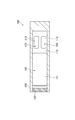
- FIG. 2 is a diagram schematically illustrating the configuration of the control device and the exhaust gas sensor according to the first embodiment.
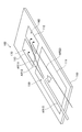
- FIG. 3 is a cross-sectional view showing a III-III cross section of FIG.
- FIG. 4 is a diagram for explaining the measurement principle of the exhaust gas sensor.
- FIG. 5 is a diagram for explaining a method of acquiring the temperature of the pump cell.
- FIG. 6 is a diagram for describing a method for determining deterioration of a sensor cell.
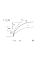
- FIG. 7 is a diagram for explaining a method for determining deterioration of a sensor cell.
- FIG. 1 is a diagram schematically illustrating a configuration of an exhaust system of a vehicle provided with a control device and an exhaust gas sensor according to the first embodiment.
- FIG. 2 is a diagram schematically illustrating the configuration of the control device and the
- FIG. 8 is a diagram showing the relationship between the temperature of the sensor cell and the degradation index.
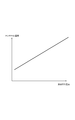
- FIG. 9 is a diagram showing the relationship between the temperature of the exhaust gas and the temperature of the sensor cell.
- FIG. 10 is a flowchart showing a flow of processing executed by the control device according to the first embodiment.
- FIG. 11 is a diagram showing temporal changes in the sensor cell temperature and the exhaust gas temperature.
- FIG. 12 is a diagram illustrating the relationship between the temperature of the exhaust pipe and the temperature of the sensor cell.
- FIG. 13 is a diagram showing the relationship between the temperature of the exhaust gas and the temperature of the exhaust pipe.
- FIG. 14 is a flowchart illustrating a flow of processing executed by the control device according to the second embodiment.
- FIG. 15 is a flowchart illustrating a flow of processing executed by the control device according to the third embodiment.
- FIG. 16 is a flowchart showing a flow of processing executed by the control device according to the fourth embodiment.
- the control device 10 is configured as a device for controlling the exhaust gas sensor 100.
- FIG. 1 schematically shows an exhaust system of a vehicle in which an exhaust gas sensor 100 is provided. As shown in the figure, an exhaust pipe 20 for guiding exhaust gas discharged from the internal combustion engine EG to the outside is connected to the internal combustion engine EG of the vehicle.
- the exhaust gas sensors 100 are for measuring the concentration of nitrogen oxides contained in the exhaust gas, and a plurality of exhaust gas sensors 100 are provided at positions in the middle of the exhaust pipe 20.
- an oxidation catalytic converter 22 and an SCR catalytic converter 23 are provided in the middle of the exhaust pipe 20, in addition to the exhaust gas sensor 100.
- the oxidation catalytic converter 22 purifies harmful substances contained in the exhaust gas.
- An oxidation catalyst (not shown) is accommodated in the oxidation catalyst converter 22.
- the oxidation catalyst is mainly composed of a ceramic support, an oxide mixture containing aluminum oxide, cerium dioxide and zirconium dioxide as components, and a noble metal catalyst such as platinum, palladium and rhodium.
- the oxidation catalyst oxidizes and purifies hydrocarbons, carbon monoxide, nitrogen oxides and the like contained in the exhaust gas.
- a particulate filter for capturing fine particles may be housed inside the oxidation catalyst converter 22.
- the SCR catalytic converter 23 is a device for further purifying exhaust gas after passing through the oxidation catalytic converter 22, and a selective reduction type catalyst (not shown) is accommodated therein.
- a catalyst in which a noble metal such as Pt is supported on the surface of a substrate such as zeolite or alumina is used.
- the catalyst is for reducing and purifying nitrogen oxides when the temperature is in the active temperature range and urea as a reducing agent is added.
- a urea addition injector 24 for adding urea is provided at a position upstream of the SCR catalytic converter 23 in the exhaust pipe 20.
- the first exhaust gas sensor 100 is provided in the exhaust pipe 20 at a position between the oxidation catalytic converter 22 and the SCR catalytic converter 23, and measures the concentration of nitrogen oxides in the exhaust gas at the position. It has become a thing.
- the first exhaust gas sensor 100 is denoted by reference numeral 101 in FIG.
- the second exhaust gas sensor 100 is provided at a position downstream of the SCR catalytic converter 23 in the exhaust pipe 20, and measures the concentration of nitrogen oxides in the exhaust gas at that position. Yes.
- the second exhaust gas sensor 100 is denoted by reference numeral 102 in FIG.
- the concentration of nitrogen oxides measured by each exhaust gas sensor 100 is transmitted to the control device 10.
- the control device 10 performs various controls of the internal combustion engine EG based on the measured nitrogen oxide concentration.
- the control includes, for example, control for adjusting the ignition timing in the internal combustion engine EG, control for adjusting the fuel injection amount, control for adjusting the urea addition amount in the urea addition injector 24, and the like.
- the control device 10 is configured as a device that controls the internal combustion engine EG in addition to the control of the exhaust gas sensor 100 described later. That is, the control device 10 also has a function as a so-called “engine ECU”. Instead of such a mode, the control device 10 is configured as a dedicated device for controlling the exhaust gas sensor 100, and may be a mode that is a control device different from the engine ECU. Good. In this case, the control device 10 contributes to the control of the internal combustion engine EG performed by the engine ECU by communicating with the engine ECU.
- a gas temperature sensor 25 is provided in the exhaust pipe 20 at a position between the oxidation catalytic converter 22 and the SCR catalytic converter 23.
- the gas temperature sensor 25 is a sensor for measuring the temperature of exhaust gas in the vicinity of the exhaust gas sensor 100.
- the temperature of the exhaust gas measured by the gas temperature sensor 25 is transmitted to the control device 10.
- a similar gas temperature sensor may be further provided at a position downstream of the SCR catalytic converter 23 in the exhaust pipe 20.
- the respective configurations of the two exhaust gas sensors 100 provided in FIG. 1 are the same as each other. Further, the control performed by the control device 10 for measuring the nitrogen oxide concentration, determining the deterioration, and the like are the same in the two exhaust gas sensors 100. Therefore, in the following description, only the configuration of the exhaust gas sensor 100 denoted by reference numeral 101 will be described, and the configuration of the exhaust gas sensor 100 denoted by reference numeral 102 will not be described.
- FIG. 2 A specific configuration of the exhaust gas sensor 100 will be described with reference to FIGS.
- positioned inside the exhaust pipe 20 among the exhaust gas sensor 100 is shown typically.
- the left end in FIG. 2, that is, the end on the side where the diffusion resistor 140 is disposed corresponds to the tip portion of the exhaust gas sensor 100 protruding inside the exhaust pipe 20.
- the exhaust gas sensor 100 includes a solid electrolyte body 110 and main body portions 120 and 130.
- the solid electrolyte body 110 is a plate-like member and is made of a solid electrolyte material such as zirconia oxide.
- the solid electrolyte body 110 has oxygen ion conductivity when in an active state at a predetermined temperature or higher.
- the solid electrolyte body 110 is formed with a pump cell 150, a sensor cell 160, and a monitor cell 170, which will be described later.
- the main body portions 120 and 130 are both plate-like members and are made of an insulating material mainly composed of alumina.
- the main body portions 120 and 130 are arranged so as to sandwich the solid electrolyte body 110 therebetween.
- a part of the surface on the solid electrolyte body 110 side recedes in a concave shape toward the side opposite to the solid electrolyte body 110.
- the space is a space into which exhaust gas to be measured is introduced.
- the space is also referred to as “measurement chamber 121”.
- a diffusion resistor 140 is disposed at the tip of the exhaust gas sensor 100.
- the measurement chamber 121 is opened to the outside, that is, the inside of the exhaust pipe 20 through the diffusion resistor 140.
- the diffusion resistor 140 is made of a ceramic material such as alumina having porous or fine pores.
- the flow of exhaust gas drawn into the measurement chamber 121 is regulated by the action of the diffusion resistor 140.
- Exhaust gas flowing into the measurement chamber 121 through the diffusion resistor 140 is supplied to a pump cell 150, a sensor cell 160, and a monitor cell 170, which will be described later.
- a part of the surface on the solid electrolyte body 110 side is recessed in a concave shape toward the side opposite to the solid electrolyte body 110.
- a space is also formed between the main body 130 and the solid electrolyte body 110.
- Part of the space (not shown) is open to the atmosphere outside the exhaust pipe 20. That is, the space is a space into which air is introduced.
- the space is also referred to as “atmosphere chamber 131”.
- the pump electrode 111, the sensor electrode 112, and the monitor electrode 113 are formed on the surface of the solid electrolyte body 110 that is in contact with the measurement chamber 121, respectively.
- the pump electrode 111 is formed at a position closer to the diffusion resistor 140 in the solid electrolyte body 110.
- the sensor electrode 112 and the monitor electrode 113 are formed on the solid electrolyte body 110 at a position opposite to the diffusion resistor 140 with the pump electrode 111 interposed therebetween.
- the sensor electrode 112 and the monitor electrode 113 are arranged so as to be aligned along the depth direction in FIG. 2 (see FIG. 3).
- the pump electrode 111 and the monitor electrode 113 are made of a Pt—Au alloy (platinum-gold alloy). All of these are active with respect to oxygen and are inactive with respect to nitrogen oxides.
- the sensor electrode 112 is made of a noble metal such as Pt (platinum) or Rh (rhodium), and is active with respect to oxygen and is also active with respect to nitrogen oxides.
- a common electrode 114 is formed on the surface of the solid electrolyte body 110 that is in contact with the atmospheric chamber 131.
- the common electrode 114 is formed in a range that overlaps all of the pump electrode 111, the sensor electrode 112, and the monitor electrode 113 when viewed along a direction perpendicular to the solid electrolyte body 110 as shown in FIG. Yes.
- the common electrode 114 is formed of a material mainly containing Pt (platinum).
- a current flows between the pump electrode 111 and the common electrode 114.
- the value of the current is a value proportional to the amount of oxygen exhausted from the exhaust gas and is a value proportional to the oxygen concentration of the exhaust gas. That is, it can be said that the pump cell 150 outputs a signal having a magnitude corresponding to the oxygen concentration of the exhaust gas, that is, the above-described current.
- the control device 10 described later can acquire the oxygen concentration of the exhaust gas present in the measurement chamber 121 based on the value of the current.
- the part sandwiched between the sensor electrode 112 and the common electrode 114 in the sensor electrode 112, the common electrode 114, and the solid electrolyte body 110 corresponds to the concentration of residual oxygen and nitrogen oxide contained in the exhaust gas.
- the exhaust gas whose concentration of nitrogen oxides and residual oxygen is measured by the sensor cell 160 is an exhaust gas after oxygen is exhausted in the pump cell 150.
- the sensor cell 160 corresponds to one of “second cells” in the present embodiment.
- a portion of the monitor electrode 113, the common electrode 114, and the solid electrolyte body 110 sandwiched between the monitor electrode 113 and the common electrode 114 is a signal having a magnitude corresponding to the concentration of residual oxygen contained in the exhaust gas. That is, it is a part that functions as the monitor cell 170 that outputs the current.
- the exhaust gas whose residual oxygen concentration is measured by the monitor cell 170 is an exhaust gas after oxygen is exhausted in the pump cell 150.
- the monitor cell 170 corresponds to one of the “second cells” in the present embodiment, together with the sensor cell 160 described above.
- the second cell in the present embodiment outputs a signal having a magnitude corresponding to the concentration of residual oxygen contained in the exhaust gas after oxygen is exhausted by the pump cell 150 (first cell). 170 and a sensor cell 160 that outputs a signal having a magnitude corresponding to the concentration of residual oxygen and nitrogen oxides contained in the exhaust gas after the oxygen is exhausted by the pump cell 150.
- the exhaust gas that has flowed into the measurement chamber 121 through the diffusion resistor 140 flows along the pump cell 150 and is then supplied to the sensor cell 160 and the monitor cell 170, respectively.
- a flow of exhaust gas is schematically shown by a plurality of arrows.
- What is indicated by an arrow AR10 is a flow of oxygen discharged by the pump cell 150 after flowing into the measurement chamber 121 through the diffusion resistor 140.
- the pump cell 150 most of the oxygen contained in the exhaust gas is removed, but it is difficult to completely remove the oxygen. For this reason, a slight amount of oxygen reaches each of the sensor cell 160 and the monitor cell 170.
- What is indicated by an arrow AR11 is a flow of oxygen reaching the sensor cell 160
- what is indicated by an arrow AR12 is a flow of oxygen reaching the monitor cell 170.
- the pump electrode 111 and the monitor electrode 113 are both inactive to nitrogen oxides. For this reason, the nitrogen oxides contained in the exhaust gas flowing into the measurement chamber 121 are not exhausted by the pump cell 150 and the monitor cell 170 but reach the sensor electrode 112 of the sensor cell 160 as they are. What is indicated by an arrow AR20 is the flow of nitrogen oxides that reaches the sensor cell 160 in this way.
- both the nitrogen oxide (arrow AR20) and the remaining oxygen (arrow AR11) reach the sensor cell 160.
- size of the electric current which flows through the sensor cell 160 shows the density
- the magnitude of the current flowing through the monitor cell 170 indicates the concentration of oxygen contained in the exhaust gas. Accordingly, the current value obtained by subtracting the value of the current flowing through the monitor cell 170 from the value of the current flowing through the sensor cell 160 indicates the concentration of only nitrogen oxides. In such an exhaust gas sensor 100, it is possible to suppress the influence of oxygen contained in the exhaust gas and accurately measure the concentration of nitrogen oxides.
- a heater 180 is embedded in the main body 130.
- the heater 180 generates heat inside the main body 130 and heats each of the pump cell 150, the sensor cell 160, and the monitor cell 170.
- the heater 180 maintains the temperature at which the solid electrolyte body 110 becomes active.
- the output of the heater 180 (that is, the amount of generated heat) is adjusted by the control device 10.
- the configuration of the control device 10 will be described with continued reference to FIG.
- the control device 10 is configured as a computer system having a CPU, a ROM, a RAM, and the like.
- the control device 10 includes a concentration detection unit 11, an internal combustion engine control unit 12, a deterioration determination unit 13, a gas temperature acquisition unit 14, a cell temperature estimation unit 15, and a cell current acquisition unit 16 as functional control blocks. And a pipe temperature acquisition unit 17 and a heater control unit 18.
- the concentration detector 11 is a portion that detects the concentration of nitrogen oxides contained in the exhaust gas based on signals (currents in the present embodiment) output from the monitor cell 170 and the sensor cell 160, respectively. As already described, the concentration detection unit 11 detects the concentration of nitrogen oxide based on the current value obtained by subtracting the value of the current flowing through the monitor cell 170 from the value of the current flowing through the sensor cell 160.
- the internal combustion engine control unit 12 is a part that controls the internal combustion engine EG based on the nitrogen oxide concentration detected by the concentration detection unit 11.
- the internal combustion engine control unit 12 adjusts the fuel injection amount of the internal combustion engine EG and the like so that the concentration of nitrogen oxide detected by the exhaust gas sensor 100 approaches zero.
- the control device 10 may be configured as a dedicated device for controlling the exhaust gas sensor 100 and may be a control device different from the engine ECU.
- the internal combustion engine control unit 12 is configured as a part of the engine ECU.
- the deterioration determining unit 13 is a part that determines whether or not the sensor cell 160 (second cell) has deteriorated.
- the sensor cell 160 When the sensor cell 160 is deteriorated, the value of the current flowing through the sensor cell 160 becomes smaller than that in the normal state even when the concentration of nitrogen oxides contained in the exhaust gas is the same. As a result, the concentration measurement by the exhaust gas sensor 100 cannot be performed accurately. Therefore, the deterioration determination unit 13 periodically performs processing for determining whether or not the sensor cell 160 has deteriorated. Specific contents of the processing will be described later.
- the gas temperature acquisition part 14 is a part which performs the process which acquires the temperature of exhaust gas.
- the gas temperature acquisition unit 14 acquires the temperature of exhaust gas passing through the vicinity of the exhaust gas sensor 100 in the exhaust pipe 20 based on a signal from the gas temperature sensor 25 shown in FIG.
- the cell temperature estimation part 15 is a part which performs the process which estimates the temperature of the sensor cell 160 (2nd cell).
- the cell temperature estimation unit 15 estimates the temperature of the sensor cell 160 based on the temperature of the exhaust gas acquired by the gas temperature acquisition unit 14. The estimation method will be described later.
- the cell current acquisition unit 16 is a part that performs a process of acquiring the value of the current flowing through the sensor cell 160 (second cell).
- the value of the current acquired by the cell current acquisition unit 16 is used for calculation of a degradation index described later.
- the piping temperature acquisition part 17 is a part which performs the process which acquires the temperature of the vicinity of the part to which the exhaust gas sensor 100 is attached among the exhaust piping 20. FIG. The acquisition method will be described later.
- the heater control unit 18 is a part that controls the heater 180.
- the heater control unit 18 measures the temperature of the pump cell 150 and adjusts the heat generation amount of the heater 180 so that the temperature becomes a predetermined target temperature. Thereby, the solid electrolyte body 110 of the exhaust gas sensor 100 is maintained in an active state.
- FIG. 5 shows an example of the change over time of the applied voltage applied between the pump electrode 111 and the common electrode 114.
- the heater controller 18 temporarily increases the applied voltage. In the example of FIG. 5, the applied voltage increases from V0 to V10 in the period from time t1 to time t2.
- the heater control unit 18 calculates the impedance of the pump cell 150 by dividing the increase amount of the applied voltage during the period from time t1 to time t2 by the increase amount of the current during the same period.
- the heater control unit 18 acquires the temperature of the pump cell 150 by referring to the impedance calculated as described above and the map.
- the applied voltage is set to V20 smaller than V0 in the period from time t2 to time t3. After the subsequent time t3, the applied voltage is returned to the original V0.
- the applied voltage is set to V20 smaller than V0 in the period from time t2 to time t3. After the subsequent time t3, the applied voltage is returned to the original V0.
- by temporarily setting the applied voltage at the time of temperature acquisition to V20 it is possible to prevent the charge from being accumulated in the pump cell 150 over time.
- the period during which the applied voltage changes for temperature measurement is very short, on the order of microseconds. This period is a period from time t1 to time t3 in the example of FIG. Since the change in current due to the change in applied voltage is very small and negligible, it hardly affects the measurement of the oxygen concentration by the monitor cell 170, the measurement of the nitrogen oxide concentration by the sensor cell 160, or the like.
- FIG. 6A shows the time change of the voltage applied to the pump cell 150. What is shown in FIG. 6B is a time change of the current flowing through the pump cell 150.
- FIG. 6C shows the time change of the current flowing through the sensor cell 160.
- the normal control (that is, the process for measuring the nitrogen oxide concentration) is temporarily stopped at time t0, and the deterioration determination by the deterioration determination unit 13 is started from time t0. ing. At time t0, the voltage applied to the pump cell 150 is changed from the original V P 2 to a lower V P 1 (FIG. 6A).
- the current flowing through the pump cell 150 is reduced from the original I P 2 to the lower I P 1 (FIG. 6B).
- This decrease in the current flowing through the pump cell 150 means that the amount of oxygen passing through the pump cell 150 and reaching the sensor cell 160 has increased after time t0. For this reason, as indicated by a line L10 in FIG. 6C, the current flowing through the sensor cell 160 starts to increase from the time t0 and finally becomes a substantially constant value.
- the increase amount of the current flowing through the sensor cell 160 is approximately proportional to the increase amount of oxygen reaching the sensor cell 160. Therefore, if the sensor cell 160 is normal and the amount of decrease in the current flowing through the pump cell 150 (I P 2 -I P 1) is constant, the current flowing through the sensor cell 160 is always the line L10 in FIG. Should change as follows.
- a line L11 in FIG. 6C shows an example of a time change of the current flowing through the sensor cell 160 when the sensor cell 160 is deteriorated.
- the time change of the current flowing through the sensor cell 160 varies depending on the deterioration mode of the sensor cell 160. For example, when deterioration due to aggregation of the sensor electrode 112 occurs in the sensor cell 160, the time change of the current becomes a graph as shown by a line L11 in FIG. On the other hand, in the sensor cell 160, when poisoning due to gold moved from the pump electrode 111 occurs, the time change of the current becomes a graph as shown by the line L110 in FIG. 6C. . That is, while the current is lower than the value (normal value) indicated by the line L10 for a while from the time t0, the final current value after the elapse of time is substantially the same as the value indicated by the line L10. Value.
- the value of the current flowing through the sensor cell 160 in which the deterioration has occurred is lower than that in the normal state for a while from the time t0.
- the deterioration determination unit 13 determines whether the sensor cell 160 has deteriorated based on the value of the current flowing through the sensor cell 160.
- the time change of the current flowing through the sensor cell 160 changes according to the degree of deterioration of the sensor cell 160 and also changes according to the temperature of the sensor cell 160. As is well known, the current flowing through the sensor cell 160 increases as the temperature of the sensor cell 160 increases.
- a line L12 in FIG. 6C shows a time change of the current flowing through the sensor cell 160 when the sensor cell 160 has a higher temperature than usual.
- the deterioration determination unit 13 determines whether or not the sensor cell 160 has deteriorated while considering that the value of the current flowing through the sensor cell 160 changes depending on the temperature.
- the deterioration determination unit 13 calculates a deterioration index using the value of the current acquired by the cell current acquisition unit 16, that is, the value of the current flowing through the sensor cell 160, and performs the deterioration determination based on the deterioration index.
- the “degradation index” in the present embodiment is a value obtained by dividing the amount of change in the value of the current acquired by the cell current acquisition unit 16 by the amount of change in the value of the current flowing through the sensor cell 160 in the normal state. That is.
- a method for calculating the degradation index will be described with reference to FIG.
- Lines L10, L11, and L12 shown in FIG. 7 are enlarged views of the line L10 and the like shown in FIG.
- a time t10 shown in FIG. 7 is a time after a predetermined period has elapsed from the time t0 when the deterioration determination is started.
- a time t20 shown in FIG. 7 is a time after a predetermined period has elapsed since the time t10.
- the current value indicated by line L10 increases by ⁇ I S 0.
- This increase amount corresponds to “the amount of change in the value of the current flowing through the sensor cell 160 under normal conditions”, is acquired in advance by experiments or the like, and is stored in a storage device (not shown) included in the control device 10. .
- the current value indicated by the line L11 that is, the value of the current flowing through the sensor cell 160 in which deterioration has occurred, increases by ⁇ I S 1 during the period from time t10 to time t20. This increase amount is smaller than the increase amount ( ⁇ I S 0) in the normal state.
- the current value indicated by the line L12 that is, the value of the current flowing through the sensor cell 160 at a high temperature increases by ⁇ I S 2 during the period from time t10 to time t20.
- This increase amount is larger than the increase amount ( ⁇ I S 0) in the normal state.
- the calculated degradation index is ⁇ I S 0 / ⁇ I S 0, that is, 1. That is, when the sensor cell 160 has not deteriorated, the calculated deterioration index is 1.
- the calculated degradation index is ⁇ I S 1 / ⁇ I S 0, that is, a value smaller than 1. . That is, when the sensor cell 160 is deteriorated, the calculated deterioration index is a value smaller than 1. Further, the greater the degree of deterioration, the smaller the calculated deterioration index.
- the degradation determination unit 13 determines that the sensor cell 160 has degraded when the degradation index is smaller than a predetermined lower limit value TH (see FIG. 8). .
- a value smaller than 1 is set as the lower limit value TH.
- the deterioration determination unit 13 in the present embodiment uses the value obtained by dividing the value of the current acquired by the cell current acquisition unit 16 by the value of the current flowing through the sensor cell 160 at the normal time.
- a deterioration index indicating the degree of deterioration of the sensor cell 160 is calculated, and based on the deterioration index, it is determined whether or not the sensor cell 160 has deteriorated.
- the “value of the current acquired by the cell current acquisition unit 16” in the above is specifically the amount of change during the period from time t10 to time t20.
- the “value of the current flowing through the sensor cell 160 in the normal state” specifically refers to the amount of change during the period from time t10 to time t20.
- the current is The ratio itself is used as the degradation index.
- a value obtained by performing predetermined conversion on the current ratio may be used as the deterioration index. For example, a value that becomes 100% when the current ratio is 0 and becomes 0% when the current ratio is 1 may be used as the deterioration index. In this case, when the calculated deterioration index exceeds a predetermined upper limit value, it is determined that the sensor cell 160 has deteriorated.
- the current ratio may be calculated based on the current value after a sufficient time has elapsed from time t0 and becomes substantially constant. That is, the value of the current acquired by the cell current acquisition unit 16 (the current value after being constant) is the value of the current flowing through the sensor cell 160 at the normal time (the current value after being constant at the normal time). A value obtained by dividing the current ratio may be calculated as a current ratio, and the deterioration index may be calculated using the current ratio.
- the final current value after the elapse of time may be the same as the current value at the normal time. Therefore, as in the present embodiment, the sensor cell 160 is deteriorated based on the change in the current value in the period immediately after the voltage applied to the pump cell 150 is changed, that is, the period from time t10 to time t20. It is preferable to determine whether or not there is.
- the calculated degradation index is ⁇ I S 2 / ⁇ I S 0, that is, a value larger than 1. . That is, when the temperature of the sensor cell 160 is higher than normal, the calculated degradation index becomes a larger value than when the temperature is low.
- the deterioration index increases to 1. It will approach. For this reason, the calculated deterioration index exceeds the lower limit value TH, and it may be erroneously determined that the sensor cell 160 has not deteriorated. In order to prevent erroneous determination, it is necessary to correct the calculated degradation index according to the temperature of the sensor cell 160.
- the correction method will be described with reference to FIG.
- the graph shown in FIG. 8 shows a correspondence relationship between the temperature (horizontal axis) of the sensor cell 160 and the calculated degradation index (vertical axis) when the sensor cell 160 has not deteriorated.
- T0 shown in FIG. 8 is a preset reference temperature of the sensor cell 160.
- the calculated deterioration index is 1.
- the calculated deterioration index becomes a value larger than 1.
- the calculated deterioration index becomes a value smaller than 1.
- the graph indicating the correspondence between the temperature of the sensor cell 160 and the calculated deterioration index is a linear graph rising upward. This correspondence relationship is acquired in advance by experiments or the like, and is stored in a storage device (not shown) included in the control device 10.
- the fluctuation amount PR1 is a value obtained by subtracting 1 from the calculated deterioration index, and can be expressed as a function of the temperature of the sensor cell 160.
- the fluctuation amount PR1 corresponding to the temperature of the sensor cell 160 acquired by the cell temperature estimation unit 15 can be acquired. If correction is performed by subtracting the fluctuation amount PR1 from the calculated deterioration index, a deterioration index excluding the fluctuation due to the influence of temperature can be obtained.
- the deterioration determination unit 13 determines whether or not the sensor cell 160 has deteriorated by comparing the corrected deterioration index with the lower limit value TH.
- the degradation determination unit 13 in the present embodiment corrects the degradation index based on the temperature of the sensor cell 160 (second cell) estimated by the cell temperature estimation unit 15, and based on the corrected degradation index.
- the sensor cell 160 is configured to determine whether or not the deterioration has occurred. Thereby, even when the temperature of the sensor cell 160 is higher or lower than the reference temperature, it can be accurately determined whether or not the sensor cell 160 has deteriorated.
- the graph shown in FIG. 8 may be a downward-sloping graph depending on how to set the period for calculating the degradation index, that is, the period from time t10 to time t20 shown in FIG. Even in this case, the calculated degradation index can be corrected by the fluctuation amount PR1 by the same method as described above.
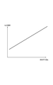
- the temperature estimation method by the cell temperature estimation unit 15 will be described with reference to FIG.
- the graph shown in FIG. 9 shows the correspondence between the temperature of the exhaust gas (horizontal axis) acquired by the gas temperature acquisition unit 14 and the temperature of the sensor cell 160 (vertical axis). As shown in the figure, the temperature of the sensor cell 160 tends to increase as the temperature of the exhaust gas acquired by the gas temperature acquisition unit 14 increases.
- the graph indicating the correspondence between the temperature of the exhaust gas and the temperature of the sensor cell 160 is a straight graph rising upward.
- This correspondence relationship is acquired in advance by experiments or the like, and is stored in a storage device (not shown) included in the control device 10.
- the cell temperature estimation unit 15 can estimate the temperature of the sensor cell 160 corresponding to the temperature of the exhaust gas acquired by the gas temperature acquisition unit 14 by referring to this correspondence relationship. Thereafter, the deterioration index is corrected as described above based on the estimated temperature of the sensor cell 160.
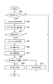
- the flow of processing executed by the control device 10 in order to realize the deterioration determination of the sensor cell 160 (second cell) as described above will be described with reference to FIG.
- the series of processing shown in FIG. 10 is repeatedly executed mainly by the deterioration determination unit 13 in the control device 10 every time a predetermined control cycle elapses.
- the determination condition is set in advance as a condition necessary for the deterioration determination by the deterioration determination unit 13 to be performed.
- the determination condition is that the timing is after the internal combustion engine EG has stopped and before 3 seconds have elapsed since the internal combustion engine EG stopped.
- FIG. 11A is a graph showing the change over time in the temperature of the exhaust gas in the exhaust pipe 20.
- FIG. 11B is a graph showing the change over time of the temperature of the sensor cell 160.
- the internal combustion engine EG is operating during the period before time t30, and the internal combustion engine EG is stopped during the period after time t30.
- the temperature of the exhaust gas in the exhaust pipe 20 gradually decreases. go.
- the temperature of the exhaust gas decreases by about 100 ° C. within 100 seconds.
- the temperature of the sensor cell 160 hardly decreases even after the time t30 when the internal combustion engine EG stops (FIG. 11B).
- the temperature of the sensor cell 160 decreased only by about 5 ° C. within 100 seconds. This is presumably because almost the entire exhaust gas sensor 100 shown in FIG. 2 is covered with a cover (not shown), and the thermal resistance between the sensor cell 160 and the exhaust gas is increased.
- the determination condition is set as described above, and the deterioration determination is started at a timing before 3 seconds have elapsed since the internal combustion engine EG stopped.
- step S01 determines whether the determination condition is satisfied. If it is determined in step S01 that the determination condition is not satisfied, the series of processing illustrated in FIG. 10 is terminated without performing the deterioration determination by the deterioration determination unit 13. If it is determined that the determination condition is satisfied, the process proceeds to step S02.
- step S02 a process for acquiring the temperature of the exhaust gas is performed by the gas temperature acquisition unit 14.
- step S03 following step S02 a process of estimating the temperature of the sensor cell 160 is performed by the cell temperature estimation unit 15.
- the cell temperature estimation unit 15 estimates the temperature of the sensor cell 160 based on the temperature of the exhaust gas obtained in step S02 and the correspondence shown in FIG.
- step S04 it is determined whether or not the temperature of the sensor cell 160 estimated in step S03 is within a predetermined appropriate temperature range.
- the “appropriate temperature range” is set in advance as a temperature range of the sensor cell 160 suitable for performing the deterioration determination.
- the series of processing illustrated in FIG. 10 is terminated without performing the deterioration determination by the deterioration determination unit 13.
- an appropriate temperature range is set as a range including the reference temperature, and deterioration determination is performed only when the temperature of the sensor cell 160 is within the appropriate temperature range.
- the deterioration determination unit 13 causes the sensor cell 160 to It is configured not to determine whether or not deterioration has occurred. This prevents the deterioration determination by the deterioration determination unit 13 from being performed in a situation where it is difficult to accurately determine the deterioration.
- step S04 when the temperature of the sensor cell 160 is within the appropriate temperature range, the process proceeds to step S05.
- step S ⁇ b> 05 the process of acquiring the value of the current flowing through the sensor cell 160 is performed by the cell current acquisition unit 16.
- the value of the current flowing through the sensor cell 160 is sampled a plurality of times.
- the “predetermined period” in the above is a period including at least a period from time t10 to time t20 in FIG.
- step S06 the deterioration determination unit 13 performs a process of calculating a deterioration index.
- the method for calculating the degradation index is as already described with reference to FIG.
- step S07 following step S06 a process of correcting the deterioration index calculated in step S06 using the temperature of the sensor cell 160 estimated in step S03 is performed.
- the method of correcting the deterioration index is as already described with reference to FIG.
- step S08 it is determined whether or not the corrected deterioration index obtained in step S07 is equal to or greater than the lower limit value TH. If the deterioration index is greater than or equal to the lower limit value TH, the process proceeds to step S09. In step S09, it is determined that the sensor cell 160 has not deteriorated.
- step S08 if the deterioration index is less than the lower limit TH, the process proceeds to step S10.
- step S10 it is determined that the sensor cell 160 has deteriorated. In this case, for example, a process is performed to notify the vehicle occupant that the measurement of the concentration of nitrogen oxides by the exhaust gas sensor 100 cannot be performed accurately, for example, by turning on an LED. Instead of such an aspect, a process of correcting the measured value of the nitrogen oxide concentration by the exhaust gas sensor 100 according to the degree of deterioration of the sensor cell 160 may be performed.
- control device 10 is configured to estimate the temperature of the sensor cell 160 based on the temperature of the exhaust gas, and perform the deterioration determination of the sensor cell 160 based on the estimated temperature of the sensor cell 160. Has been.
- the temperature of the pump cell 150 is acquired by the heater controller 18 as described above.
- the sensor cell 160 is formed near the pump cell 150. For this reason, it seems that the temperature of the sensor cell 160 can be accurately acquired based on the temperature of the pump cell 150 acquired by the heater controller 18.
- the acquired temperature of the pump cell 150 is used as it is as the temperature of the sensor cell 160, or a temperature shifted by a predetermined temperature from the acquired temperature of the pump cell 150 is used as the temperature of the sensor cell 160.
- the pump cell 150 is disposed at a position on the inner side. For this reason, a temperature difference is generated between the pump cell 150 and the sensor cell 160 due to heat conduction between the exhaust gas sensor 100 and the exhaust pipe 20. Further, the temperature difference is not always constant and changes depending on the driving state of the vehicle. For this reason, it is not easy to accurately estimate the temperature of the sensor cell 160 based on the temperature of the pump cell 150.
- the deterioration determination of the sensor cell 160 is performed based on the temperature.
- the deterioration determination unit 13 in the present embodiment uses a value (current ratio) obtained by dividing the value of the current acquired by the cell current acquisition unit 16 by the value of the current flowing through the sensor cell 160 in a normal state. Thus, a deterioration index indicating the degree of deterioration of the sensor cell 160 is calculated. Further, it is determined whether or not the sensor cell 160 has deteriorated based on the deterioration index.
- the deterioration determination unit 13 corrects the deterioration index based on the temperature of the sensor cell 160 estimated by the cell temperature estimation unit 15, and determines whether or not the sensor cell 160 has deteriorated based on the corrected deterioration index. It is configured to determine. Accordingly, it is possible to accurately determine whether or not the sensor cell 160 has deteriorated based on the sensor cell 160.
- the second embodiment will be described. Hereinafter, differences from the first embodiment will be mainly described, and description of points that are common to the first embodiment will be omitted as appropriate.
- the temperature estimation method by the cell temperature estimation unit 15 is different from that of the first embodiment.
- the cell temperature estimation unit 15 according to the present embodiment estimates the temperature of the sensor cell 160 based on the temperature of the exhaust pipe 20.
- the graph shown in FIG. 12 shows the correspondence between the temperature (horizontal axis) in the vicinity of the portion of the exhaust pipe 20 where the exhaust gas sensor 100 is attached and the temperature (vertical axis) of the sensor cell 160. As shown in the figure, the temperature of the sensor cell 160 tends to increase as the temperature of the exhaust pipe 20 increases.
- the graph indicating the correspondence between the temperature of the exhaust pipe 20 and the temperature of the sensor cell 160 is a straight line graph rising upward.
- This correspondence relationship is acquired in advance by experiments or the like, and is stored in a storage device (not shown) included in the control device 10.
- the cell temperature estimation unit 15 can estimate the temperature of the sensor cell 160 corresponding to the temperature of the exhaust pipe 20 by referring to this correspondence. Thereafter, the deterioration index is corrected as described above based on the estimated temperature of the sensor cell 160.
- the method for obtaining the temperature of the exhaust pipe 20 will be described.
- the graph shown in FIG. 13 shows the correspondence between the temperature of the exhaust gas passing through the inside of the exhaust pipe 20 (horizontal axis) and the temperature of the exhaust pipe 20 (vertical axis). As shown in the figure, the temperature of the exhaust pipe 20 tends to increase as the temperature of the exhaust gas increases.
- the graph showing the correspondence between the temperature of the exhaust gas and the temperature of the exhaust pipe 20 is a linear graph that rises to the right.
- This correspondence relationship is acquired in advance by experiments or the like, and is stored in a storage device (not shown) included in the control device 10.
- the pipe temperature acquisition unit 17 can estimate the temperature of the exhaust pipe 20 corresponding to the temperature of the exhaust gas by referring to this correspondence.
- a plurality of correspondence relationships shown in FIG. 13 may be stored according to parameters other than the exhaust gas temperature.
- a plurality of correspondence relationships shown in FIG. 13 are stored according to the temperature of air supplied to the internal combustion engine EG from an unillustrated air supply pipe, the load state of the internal combustion engine EG, the continuous operation time of the internal combustion engine EG, and the like. It is good also as being done.
- the pipe temperature acquisition unit 17 selects the correspondence according to the situation at that time, and then, based on the correspondence and the temperature of the exhaust gas acquired by the gas temperature acquisition unit 14, the exhaust pipe. A temperature of 20 will be estimated.
- the pipe temperature acquisition unit 17 is configured to acquire the temperature of the exhaust pipe 20 to which the exhaust gas sensor 100 is attached based on at least the temperature of the exhaust gas acquired by the gas temperature acquisition unit 14. Yes. Further, the cell temperature estimation unit 15 in the present embodiment is configured to estimate the temperature of the sensor cell 160 (second cell) based on the temperature of the exhaust pipe 20 acquired by the pipe temperature acquisition unit 17.
- step S03 in FIG. 10 is replaced with step S13, and a new step S12 is inserted between step S02 and step S13.
- step S02 after the process of acquiring the temperature of the exhaust gas is performed by the gas temperature acquisition unit 14, the process proceeds to step S12 in the present embodiment.
- step S ⁇ b> 12 processing for acquiring the temperature of the exhaust pipe 20 is performed by the pipe temperature acquisition unit 17.
- the acquisition method is as already described with reference to FIG.
- step S13 a process of estimating the temperature of the sensor cell 160 is performed by the cell temperature estimation unit 15.
- processing for estimating the temperature of the sensor cell 160 is performed based on the temperature of the exhaust pipe 20 acquired in step S12.
- the estimation method is as already described with reference to FIG.
- control device 10 acquires the temperature of the exhaust pipe 20 based on at least the temperature of the exhaust gas, and estimates the temperature of the sensor cell 160 based on the temperature of the exhaust pipe 20. It is configured. Even in such an aspect, the same effects as those described in the first embodiment can be obtained.
- the third embodiment will be described. Hereinafter, differences from the first embodiment will be mainly described, and description of points that are common to the first embodiment will be omitted as appropriate.
- the cell temperature estimation unit 15 is configured to estimate each of the temperature of the sensor cell 160 and the temperature of the monitor cell 170.
- the deterioration determination unit 13 is configured to perform deterioration determination of the monitor cell 170 based on the temperature of the monitor cell 170 in addition to performing deterioration determination of the sensor cell 160 based on the temperature of the sensor cell 160.
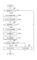
- step 15 is a process executed by the control device 10 according to the present embodiment, and is executed in parallel with the series of processes shown in FIG. In this process, steps S03 to S10 in FIG. 10 are replaced with steps S23 to S30.
- the deterioration determination of the sensor cell 160 is performed by a series of processes shown in FIG. 10
- the deterioration determination of the monitor cell 170 is performed by a series of processes shown in FIG.
- step S ⁇ b> 23 a process for estimating the temperature of the monitor cell 170 is performed by the cell temperature estimation unit 15.
- the estimation method is the same as the method for estimating the temperature of the sensor cell 160.
- a storage device (not shown) included in the control device 10 stores a correspondence relationship between the temperature of the exhaust gas and the temperature of the monitor cell 170, that is, the same correspondence relationship as that shown in FIG.
- the cell temperature estimation unit 15 estimates the temperature of the monitor cell 170 based on the temperature of the exhaust gas obtained in step S02 and the corresponding relationship.
- step S24 it is determined whether or not the temperature of the monitor cell 170 estimated in step S23 is within a predetermined appropriate temperature range.
- the “appropriate temperature range” here is the same as the appropriate temperature range used for the determination in step S04 in FIG.
- the appropriate temperature range for the monitor cell 170 may be set as a range different from the appropriate temperature range for the sensor cell 160. When the temperature of the monitor cell 170 is outside the appropriate temperature range, the series of processing shown in FIG.
- step S24 when the temperature of the monitor cell 170 is within the appropriate temperature range, the process proceeds to step S25.
- step S ⁇ b> 25 the cell current acquisition unit 16 performs processing for acquiring the value of the current flowing through the monitor cell 170.
- the method for obtaining the current value is the same as the method for obtaining the value of the current flowing through the sensor cell 160 in step S04 in FIG.
- step S26 the deterioration determination unit 13 performs a process of calculating a deterioration index for the monitor cell 170.
- the method for calculating the deterioration index is the same as the method for calculating the deterioration index for the sensor cell 160, that is, the method described with reference to FIG.
- step S27 following step S26 processing for correcting the deterioration index calculated in step S26 using the temperature of the monitor cell 170 estimated in step S23 is performed.
- the method of correcting the deterioration index is the same as the method of correcting the deterioration index for the sensor cell 160, that is, the method described with reference to FIG.
- step S28 it is determined whether or not the corrected deterioration index obtained in step S27 is equal to or higher than the lower limit value TH.
- the “lower limit value TH” here is the same as the lower limit value TH used for the determination in step S08 of FIG.
- the lower limit value TH for the monitor cell 170 may be set as a value different from the lower limit value TH for the sensor cell 160. If the deterioration index is greater than or equal to the lower limit value TH, the process proceeds to step S29. In step S29, it is determined that the monitor cell 170 has not deteriorated.
- step S28 when the deterioration index is less than the lower limit value TH, the process proceeds to step S30.
- step S30 it is determined that the monitor cell 170 has deteriorated. In this case, for example, a process is performed to notify the vehicle occupant that the measurement of the concentration of nitrogen oxides by the exhaust gas sensor 100 cannot be performed accurately, for example, by turning on an LED. Instead of such an aspect, a process of correcting the measured value of the nitrogen oxide concentration by the exhaust gas sensor 100 according to the degree of deterioration of the monitor cell 170 may be performed.
- the cell temperature estimation unit 15 is configured to estimate both the temperature of the monitor cell 170 and the temperature of the sensor cell 160, respectively. Further, the deterioration determination unit 13 in the present embodiment is configured to perform calculation and correction of the deterioration index for each of the monitor cell 170 and the sensor cell 160 that are the second cells.
- the deterioration determination unit 13 corrects the deterioration index calculated for the monitor cell 170 based on the temperature of the monitor cell 170 estimated by the cell temperature estimation unit 15, and is estimated by the cell temperature estimation unit 15. Based on the temperature of the sensor cell 160, the deterioration index calculated for the sensor cell 160 is corrected. Thereby, it is possible to perform accurate deterioration determination not only for the sensor cell 160 but also for the monitor cell 170.
- the cell temperature estimation unit 15 may estimate only the temperature of the monitor cell 170, and the deterioration determination unit 13 may perform only the deterioration determination of the monitor cell 170 based on the temperature.
- the fourth embodiment will be described. Hereinafter, differences from the first embodiment will be mainly described, and description of points that are common to the first embodiment will be omitted as appropriate.
- the deterioration determination unit 13 is configured to perform deterioration determination for each of the sensor cell 160 and the monitor cell 170. However, each deterioration determination is performed based on the temperature of the sensor cell 160 estimated by the cell temperature estimation unit 15.
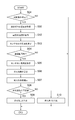
- step 16 is a process executed by the control device 10 according to the present embodiment, and is executed in parallel with the series of processes shown in FIG. In this process, steps S05 to S10 in FIG. 10 are replaced with steps S35 to S40.
- the deterioration determination of the sensor cell 160 is performed by a series of processes shown in FIG. 10
- the deterioration determination of the monitor cell 170 is performed by a series of processes shown in FIG.
- step S04 when it is determined in step S04 that the temperature of the sensor cell 160 is within the appropriate range, the process proceeds to step S35.
- step S ⁇ b> 35 a process for acquiring the value of the current flowing through the monitor cell 170 is performed by the cell current acquisition unit 16.
- the method for obtaining the current value is the same as the method for obtaining the value of the current flowing through the sensor cell 160 in step S04 in FIG.
- step S36 the deterioration determination unit 13 performs a process of calculating a deterioration index for the monitor cell 170.
- the method for calculating the deterioration index is the same as the method for calculating the deterioration index for the sensor cell 160, that is, the method described with reference to FIG.
- step S36 the temperature of the sensor cell 160 estimated in step S03 is set to the temperature of the monitor cell 170 at this time, and the deterioration index for the monitor cell 170 is calculated.
- step S37 processing for correcting the deterioration index calculated in step S36 is performed.
- the method of correcting the deterioration index is the same as the method of correcting the deterioration index for the sensor cell 160, that is, the method described with reference to FIG.
- the temperature of the sensor cell 160 estimated in step S03 is set to the temperature of the monitor cell 170 at this time, and the deterioration index for the monitor cell 170 is corrected.
- the deterioration index for the monitor cell 170 is corrected based on the estimated temperature of the sensor cell 160.
- step S38 it is determined whether or not the corrected deterioration index obtained in step S37 is greater than or equal to the lower limit value TH.
- the “lower limit value TH” here is the same as the lower limit value TH used for the determination in step S08 of FIG.
- the lower limit value TH for the monitor cell 170 may be set as a value different from the lower limit value TH for the sensor cell 160. If the deterioration index is greater than or equal to the lower limit value TH, the process proceeds to step S39. In step S39, it is determined that the monitor cell 170 has not deteriorated.
- step S38 if the deterioration index is less than the lower limit TH, the process proceeds to step S40.
- step S40 it is determined that the monitor cell 170 has deteriorated. In this case, for example, a process is performed to notify the vehicle occupant that the measurement of the concentration of nitrogen oxides by the exhaust gas sensor 100 cannot be performed accurately, for example, by turning on an LED. Instead of such an aspect, a process of correcting the measured value of the nitrogen oxide concentration by the exhaust gas sensor 100 according to the degree of deterioration of the monitor cell 170 may be performed.
- the deterioration determination unit 13 corrects the deterioration index calculated for the monitor cell 170 and calculates the sensor cell 160 based on the temperature of the sensor cell 160 estimated by the cell temperature estimation unit 15. The deterioration index is corrected. Even if it is such an aspect, there exists an effect similar to what was demonstrated about 1st Embodiment.
- the deterioration determination unit 13 calculates the correction of the deterioration index calculated for the monitor cell 170 and the sensor cell 160 based on the temperature of the monitor cell 170 estimated by the cell temperature estimation unit 15. It is also possible to adopt a mode in which correction of the deterioration index is performed.
- the control apparatus and control method described in the present disclosure includes one or more dedicated units provided by configuring a processor and a memory programmed to perform one or more functions embodied by a computer program. It may be realized by a computer.
- the control device and the control method described in the present disclosure may be realized by a dedicated computer provided by configuring a processor including one or more dedicated hardware logic circuits.
- a control apparatus and a control method described in the present disclosure are configured by a combination of a processor and a memory programmed to perform one or more functions and a processor including one or more hardware logic circuits. It may be realized by one or a plurality of dedicated computers.
- the computer program may be stored in a computer-readable non-transitional tangible recording medium as instructions executed by the computer.
- the dedicated hardware logic circuit and the hardware logic circuit may be realized by a digital circuit including a plurality of logic circuits or an analog circuit.
Landscapes
- Engineering & Computer Science (AREA)
- Chemical & Material Sciences (AREA)
- Combustion & Propulsion (AREA)
- Mechanical Engineering (AREA)
- General Engineering & Computer Science (AREA)
- Chemical Kinetics & Catalysis (AREA)
- Combined Controls Of Internal Combustion Engines (AREA)
- Exhaust Gas After Treatment (AREA)
Priority Applications (1)
| Application Number | Priority Date | Filing Date | Title |
|---|---|---|---|
| DE112019002887.1T DE112019002887T5 (de) | 2018-06-08 | 2019-05-21 | Steuerungsvorrichtung |
Applications Claiming Priority (2)
| Application Number | Priority Date | Filing Date | Title |
|---|---|---|---|
| JP2018-110377 | 2018-06-08 | ||
| JP2018110377A JP6900937B2 (ja) | 2018-06-08 | 2018-06-08 | 制御装置 |
Publications (1)
| Publication Number | Publication Date |
|---|---|
| WO2019235212A1 true WO2019235212A1 (ja) | 2019-12-12 |
Family
ID=68770822
Family Applications (1)
| Application Number | Title | Priority Date | Filing Date |
|---|---|---|---|
| PCT/JP2019/020121 Ceased WO2019235212A1 (ja) | 2018-06-08 | 2019-05-21 | 制御装置 |
Country Status (3)
| Country | Link |
|---|---|
| JP (1) | JP6900937B2 (https=) |
| DE (1) | DE112019002887T5 (https=) |
| WO (1) | WO2019235212A1 (https=) |
Cited By (1)
| Publication number | Priority date | Publication date | Assignee | Title |
|---|---|---|---|---|
| CN116096991A (zh) * | 2020-07-31 | 2023-05-09 | 株式会社电装 | 传感器控制装置 |
Citations (3)
| Publication number | Priority date | Publication date | Assignee | Title |
|---|---|---|---|---|
| JP2003050227A (ja) * | 2001-05-31 | 2003-02-21 | Denso Corp | ガス濃度センサのヒータ制御装置 |
| JP4767621B2 (ja) * | 2004-10-02 | 2011-09-07 | ロベルト・ボッシュ・ゲゼルシャフト・ミト・ベシュレンクテル・ハフツング | 内燃機関の排気ガス領域内に配置されたNOxセンサの診断方法および装置 |
| JP2015206767A (ja) * | 2014-04-23 | 2015-11-19 | 株式会社デンソー | 排出ガスセンサのヒータ制御装置 |
-
2018
- 2018-06-08 JP JP2018110377A patent/JP6900937B2/ja not_active Expired - Fee Related
-
2019
- 2019-05-21 WO PCT/JP2019/020121 patent/WO2019235212A1/ja not_active Ceased
- 2019-05-21 DE DE112019002887.1T patent/DE112019002887T5/de not_active Withdrawn
Patent Citations (3)
| Publication number | Priority date | Publication date | Assignee | Title |
|---|---|---|---|---|
| JP2003050227A (ja) * | 2001-05-31 | 2003-02-21 | Denso Corp | ガス濃度センサのヒータ制御装置 |
| JP4767621B2 (ja) * | 2004-10-02 | 2011-09-07 | ロベルト・ボッシュ・ゲゼルシャフト・ミト・ベシュレンクテル・ハフツング | 内燃機関の排気ガス領域内に配置されたNOxセンサの診断方法および装置 |
| JP2015206767A (ja) * | 2014-04-23 | 2015-11-19 | 株式会社デンソー | 排出ガスセンサのヒータ制御装置 |
Cited By (2)
| Publication number | Priority date | Publication date | Assignee | Title |
|---|---|---|---|---|
| CN116096991A (zh) * | 2020-07-31 | 2023-05-09 | 株式会社电装 | 传感器控制装置 |
| CN116096991B (zh) * | 2020-07-31 | 2025-10-28 | 株式会社电装 | 传感器控制装置 |
Also Published As
| Publication number | Publication date |
|---|---|
| JP6900937B2 (ja) | 2021-07-14 |
| DE112019002887T5 (de) | 2021-03-04 |
| JP2019210916A (ja) | 2019-12-12 |
Similar Documents
| Publication | Publication Date | Title |
|---|---|---|
| US11249043B2 (en) | Control device for gas sensor | |
| JP6558109B2 (ja) | ガス濃度検出装置 | |
| CN108343496A (zh) | 催化器劣化诊断方法和催化器劣化诊断系统 | |
| JP6966348B2 (ja) | 特定ガス濃度測定装置及び特定ガス濃度測定システム | |
| WO2022123866A1 (ja) | ガスセンサ | |
| JP7234976B2 (ja) | 制御装置 | |
| JP6658672B2 (ja) | ガスセンサ制御装置 | |
| JP6965578B2 (ja) | ガスセンサ制御装置 | |
| WO2016121380A1 (ja) | 内燃機関制御装置 | |
| JP6344262B2 (ja) | 排気センサ | |
| KR102028420B1 (ko) | 배기 가스 센서의 작동 방법 및 장치 | |
| WO2019235212A1 (ja) | 制御装置 | |
| US10731588B2 (en) | Control apparatus for exhaust gas sensor | |
| JP7234977B2 (ja) | 制御装置 | |
| JP6708168B2 (ja) | ガスセンサ制御装置 | |
| US10859021B2 (en) | Apparatus for controlling air fuel ratio | |
| WO2020045148A1 (ja) | 制御装置 | |
| US12181439B2 (en) | Gas sensor | |
| WO2018221528A1 (ja) | ガスセンサ制御装置 | |
| JP2019124185A (ja) | 制御装置 | |
| JP6984696B2 (ja) | ガスセンサの制御装置 | |
| WO2023085015A1 (ja) | 制御装置 | |
| WO2017110553A1 (ja) | 内燃機関のガス濃度検出装置 | |
| JP2018059941A (ja) | ガスセンサ制御装置 | |
| WO2017086202A1 (ja) | ガス濃度検出装置 |
Legal Events
| Date | Code | Title | Description |
|---|---|---|---|
| 121 | Ep: the epo has been informed by wipo that ep was designated in this application |
Ref document number: 19815399 Country of ref document: EP Kind code of ref document: A1 |
|
| 122 | Ep: pct application non-entry in european phase |
Ref document number: 19815399 Country of ref document: EP Kind code of ref document: A1 |