WO2019234965A1 - インクジェット記録装置 - Google Patents
インクジェット記録装置 Download PDFInfo
- Publication number
- WO2019234965A1 WO2019234965A1 PCT/JP2019/002205 JP2019002205W WO2019234965A1 WO 2019234965 A1 WO2019234965 A1 WO 2019234965A1 JP 2019002205 W JP2019002205 W JP 2019002205W WO 2019234965 A1 WO2019234965 A1 WO 2019234965A1
- Authority
- WO
- WIPO (PCT)
- Prior art keywords
- recording apparatus
- ink
- head
- inkjet recording
- container
- Prior art date
Links
- 238000004140 cleaning Methods 0.000 claims abstract description 175
- 239000007788 liquid Substances 0.000 claims abstract description 95
- 239000002245 particle Substances 0.000 claims abstract description 31
- 238000003780 insertion Methods 0.000 claims abstract description 17
- 230000037431 insertion Effects 0.000 claims abstract description 17
- 239000002699 waste material Substances 0.000 claims description 63
- 238000007599 discharging Methods 0.000 claims description 4
- 238000001514 detection method Methods 0.000 claims description 2
- 239000002904 solvent Substances 0.000 description 40
- 238000001035 drying Methods 0.000 description 16
- 238000000034 method Methods 0.000 description 12
- 238000011084 recovery Methods 0.000 description 6
- 238000004519 manufacturing process Methods 0.000 description 5
- 238000007789 sealing Methods 0.000 description 5
- 230000001276 controlling effect Effects 0.000 description 2
- 238000010586 diagram Methods 0.000 description 2
- 230000005684 electric field Effects 0.000 description 2
- 238000012545 processing Methods 0.000 description 2
- 230000001105 regulatory effect Effects 0.000 description 2
- 238000005406 washing Methods 0.000 description 2
- 238000013459 approach Methods 0.000 description 1
- 235000013361 beverage Nutrition 0.000 description 1
- 230000000903 blocking effect Effects 0.000 description 1
- 239000002537 cosmetic Substances 0.000 description 1
- 239000003651 drinking water Substances 0.000 description 1
- 235000020188 drinking water Nutrition 0.000 description 1
- 230000005284 excitation Effects 0.000 description 1
- 238000009434 installation Methods 0.000 description 1
- 238000012986 modification Methods 0.000 description 1
- 230000004048 modification Effects 0.000 description 1
- 230000002093 peripheral effect Effects 0.000 description 1
- 239000000126 substance Substances 0.000 description 1
Images


Classifications
-
- B—PERFORMING OPERATIONS; TRANSPORTING
- B41—PRINTING; LINING MACHINES; TYPEWRITERS; STAMPS
- B41J—TYPEWRITERS; SELECTIVE PRINTING MECHANISMS, i.e. MECHANISMS PRINTING OTHERWISE THAN FROM A FORME; CORRECTION OF TYPOGRAPHICAL ERRORS
- B41J2/00—Typewriters or selective printing mechanisms characterised by the printing or marking process for which they are designed
- B41J2/005—Typewriters or selective printing mechanisms characterised by the printing or marking process for which they are designed characterised by bringing liquid or particles selectively into contact with a printing material
- B41J2/01—Ink jet
- B41J2/135—Nozzles
- B41J2/165—Prevention or detection of nozzle clogging, e.g. cleaning, capping or moistening for nozzles
- B41J2/16517—Cleaning of print head nozzles
- B41J2/16552—Cleaning of print head nozzles using cleaning fluids
-
- B—PERFORMING OPERATIONS; TRANSPORTING
- B41—PRINTING; LINING MACHINES; TYPEWRITERS; STAMPS
- B41J—TYPEWRITERS; SELECTIVE PRINTING MECHANISMS, i.e. MECHANISMS PRINTING OTHERWISE THAN FROM A FORME; CORRECTION OF TYPOGRAPHICAL ERRORS
- B41J2/00—Typewriters or selective printing mechanisms characterised by the printing or marking process for which they are designed
- B41J2/005—Typewriters or selective printing mechanisms characterised by the printing or marking process for which they are designed characterised by bringing liquid or particles selectively into contact with a printing material
- B41J2/01—Ink jet
- B41J2/07—Ink jet characterised by jet control
- B41J2/075—Ink jet characterised by jet control for many-valued deflection
- B41J2/08—Ink jet characterised by jet control for many-valued deflection charge-control type
-
- B—PERFORMING OPERATIONS; TRANSPORTING
- B41—PRINTING; LINING MACHINES; TYPEWRITERS; STAMPS
- B41J—TYPEWRITERS; SELECTIVE PRINTING MECHANISMS, i.e. MECHANISMS PRINTING OTHERWISE THAN FROM A FORME; CORRECTION OF TYPOGRAPHICAL ERRORS
- B41J2/00—Typewriters or selective printing mechanisms characterised by the printing or marking process for which they are designed
- B41J2/005—Typewriters or selective printing mechanisms characterised by the printing or marking process for which they are designed characterised by bringing liquid or particles selectively into contact with a printing material
- B41J2/01—Ink jet
- B41J2/135—Nozzles
- B41J2/165—Prevention or detection of nozzle clogging, e.g. cleaning, capping or moistening for nozzles
- B41J2/16505—Caps, spittoons or covers for cleaning or preventing drying out
- B41J2/16508—Caps, spittoons or covers for cleaning or preventing drying out connected with the printer frame
Definitions
- the present invention relates to a head cleaning function of an ink jet recording apparatus.
- Patent Document 1 As background art in this technical field, there is JP-A-2015-136934 (Patent Document 1).
- Patent Document 1 as a head cleaning method of an ink jet recording apparatus, cleaning is performed by ejecting a cleaning liquid from a cleaning nozzle inside a head toward a nozzle discharge port. And the point which eliminates the cause of nozzle clogging by performing a drying process is disclosed.
- Inkjet recording devices are often used in production lines where hygiene management is important, such as food, drinking water, chemicals, and cosmetics. Therefore, it is required that the cleaning liquid and ink do not flow out into the interior of the ink jet recording apparatus, peripheral equipment, floors, and the like.
- an object of the present invention is to provide an ink jet recording apparatus having a print head cleaning function for avoiding the outflow of cleaning liquid around the ink jet recording apparatus and storing the cleaning liquid used for cleaning in a highly airtight container. That is.
- the present invention is, as an example, a main body having an ink container for storing ink for printing on a printing object and a cleaning liquid container for storing a cleaning liquid, and the ink container.
- a nozzle that discharges the connected and pressurized ink, a charging electrode that charges ink particles used for printing, a deflection electrode that deflects ink particles charged by the charging electrode, and ink particles that are not used for printing are collected.
- An ink jet recording apparatus including a print head having a gutter for performing cleaning includes a head cleaning unit having a cleaning nozzle for discharging a cleaning liquid and an insertion port into which the print head can be inserted.
- an ink jet recording apparatus provided with a head cleaning unit for a print head that can prevent the cleaning liquid from flowing around the ink jet recording apparatus and eliminate the cause of nozzle clogging.
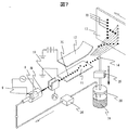
- FIG. 1 is a perspective view illustrating a usage state of an ink jet recording apparatus in Embodiment 1.
- FIG. FIG. 3 is a diagram illustrating a path configuration of the ink jet recording apparatus according to the first exemplary embodiment.
- 4 is a cross-sectional view of a head cleaning unit in Embodiment 1.
- FIG. 3 is a cross-sectional view of a head cleaning unit in which a print head in Example 1 is inserted.
- FIG. 3 is a cross-sectional view illustrating a connection state between a head cleaning unit and a waste liquid container in Embodiment 1.
- FIG. 3 is a cross-sectional view illustrating a state where a waste liquid container is removed from the head cleaning unit in the first embodiment.
- FIG. 6 is a flowchart of the operation of the head cleaning unit according to the first embodiment. It is a perspective view which shows the principle of operation of an inkjet recording device. 6 is a cross-sectional view of a head cleaning unit in Embodiment 2. FIG. 6 is a cross-sectional view of a head cleaning unit in Embodiment 3. FIG.
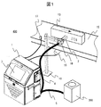
- FIG. 1 is a perspective view showing a use state of an ink jet recording apparatus 400 in the present embodiment.
- 1 is an ink jet recording apparatus main body
- 2 is a print head
- 3 is an operation display unit
- 4 is a conduit (print head)
- 5 is a conduit (head cleaning unit)
- 300 is a head cleaning unit (external unit).
- the ink jet recording apparatus 400 includes an operation display unit 3 in the ink jet recording apparatus main body 1, and includes a print head 2 and a head cleaning unit 300 outside.
- the ink jet recording apparatus main body 1 and the print head 2 are connected by a conduit 4 of about 3000 mm.
- the ink jet recording apparatus main body 1 and the head cleaning unit 300 are connected by a conduit 5 of about 3500 mm.
- Reference numeral 13 denotes a print object on which numbers and characters are printed
- 15 denotes a belt conveyor that conveys the print object
- 16 denotes a rotary encoder that measures the conveyance distance of the belt conveyor
- 17 denotes a print sensor
- 18 denotes a print head.
- the ink jet recording apparatus 400 is installed, for example, in a production line in a factory where food and beverages are produced, the ink jet recording apparatus main body 1 is installed at a position where the user can operate, and the print head 2 is a belt conveyor 15 or the like. It is installed at a position where it can approach the print target 13 fed on the production line. At this time, the fixing jig 19 may be fixed to the mounting stand 18 on the print head 2. In order to print on the production line such as the belt conveyor 15 with the same width regardless of the feeding speed, the encoder 16 that outputs a signal corresponding to the feeding speed to the ink jet recording apparatus 400 and the printing object 13 are detected.
- a print sensor 17 that outputs a signal for instructing printing to the inkjet recording apparatus 400 is installed, and each is connected to a control unit (not shown) in the inkjet recording apparatus main body 1.
- the control unit controls the charge amount and charging timing of the ink particles ejected from the nozzle, and charging and deflection are performed while the print target 13 passes near the print head 2. Printing is performed by attaching the ink particles thus adhered to the printing object 13.
- the head cleaning unit 300 is installed near the print head 2.
- the conduit 5 is longer than the conduit 4 in order to provide freedom of installation of the head cleaning unit 300.
- the print head 2 is installed in the head cleaning unit 300 when the print head is cleaned and dried. Then, air and a solvent (hereinafter also referred to as a cleaning liquid) sent from the inkjet recording apparatus main body 1 to the head cleaning unit 300 through the conduit 5 are ejected from nozzles in the head cleaning unit, so that the print head 2 is cleaned and dried. It has become.
- a solvent hereinafter also referred to as a cleaning liquid
- FIG. 7 20 is a main ink container
- 7A is ink
- 24 is a pump for supplying and supplying ink (for supply)
- 9 is an electrostrictive element that vibrates at a predetermined frequency when a voltage is applied
- 8 discharges ink.
- the nozzle 7B is an ink column.
- 10 is a charging electrode for charging ink particles
- 7C is ink particles
- 11 is a ground deflection electrode
- 12 is a plus deflection electrode
- 13 is a printing object to be printed
- 14 is a gutter for collecting ink particles that are not printed.
- the ink 7A in the main ink container 20 is sucked and pressurized by a pump (for supply) 24 to become an ink column 7B and is discharged from the nozzle 8.
- the nozzle 8 is provided with an electrostrictive element 9, and the ink column 7B ejected from the nozzle 8 is made into particles by applying vibration to the ink at a predetermined frequency.
- the number of ink particles 7C thus generated is determined by the frequency of the excitation voltage applied to the electrostrictive element 9, and is the same as the frequency.
- the ink particles 7 ⁇ / b> C can be charged by applying a voltage having a magnitude corresponding to the print information at the charging electrode 10.
- the ink particles 7 ⁇ / b> C charged by the charging electrode 10 fly in the electric field between the ground deflection electrode 11 and the plus deflection electrode 12.
- the deflection electric field is formed between the plus deflection electrode 12 to which a high voltage of 1 to 7 kV is applied and the installed ground deflection electrode 11, and the charged ink particles 7C have a force proportional to the charge amount. In response, it deflects and flies toward the printing object 13 to land.
- the landing position of the ink particle 7C changes in the deflection direction according to the charge amount, and the production line moves the print target 13 in the direction orthogonal to the deflection direction, so that the ink particle 7C also moves in the direction orthogonal to the deflection direction.
- Particles can be landed, and a plurality of landed ink particles 7D constitute characters to perform printing.
- the ink particles 7C that have not been used for printing fly linearly between the plus deflection electrodes 12 and are captured by the gutter 14, and then sucked by the pump (for collection) 25 and collected in the main ink container 20.
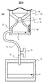
- FIG. 2 is a diagram illustrating a path configuration of the ink jet recording apparatus according to the present exemplary embodiment.
- the ink jet recording apparatus main body 1 is provided with a main ink container 20 that holds the circulating ink 7A.
- the main ink container 20 holds the liquid in the main ink container 20 therein.
- a liquid level sensor 46 for detecting whether or not a reference liquid level that is an appropriate amount is reached is provided.
- the main ink container 20 is connected to the viscosity measuring device 43 via the path 201 in order to grasp the viscosity of the ink 7A in the main ink container 20.
- the viscosity measuring device 43 is connected to an electromagnetic valve (for supply) 34 that opens and closes the path via a path 202, and the solenoid valve (for supply) 34 is used to suck and pump ink 7 ⁇ / b> A via the path 203. It is connected to a pump (for supply) 24 to be used.
- the pump (for supply) 24 is connected via a path 204 to a filter (for supply) 28 that removes foreign matters mixed in the ink 7A.
- the filter (for supply) 28 is connected to a pressure regulating valve 33 that adjusts the pressure to an appropriate pressure for printing the ink 7A pumped from the pump (for supply) 24 via the path 205, and the pressure regulating valve 33 is connected to the path.
- a pressure sensor 31 that measures the pressure of the ink 7 ⁇ / b> A supplied to the nozzle 8 via 206 is provided.
- the pressure sensor 31 is connected to a switching valve 42 for controlling whether or not the ink 7A is supplied to the nozzle 8 via a path 207 passing through the conduit 4.
- the switching valve 42 is connected via a path 209 to the nozzle 8 having a discharge port for discharging the ink 7A.
- the switching valve 42 is a three-way solenoid valve.
- An ink supply path 207 and a cleaning path 237 are connected to the switching valve 42, and the supply of ink and solvent to the nozzle 8 can be switched.
- the gutter 14 is connected to a filter (for recovery) 30 that removes foreign matters mixed in the ink disposed in the ink jet recording apparatus main body 1 via a path 212 passing through the conduit 4.
- the filter (for recovery) 29 is connected to an electromagnetic valve (for recovery) 35 that opens and closes the path via the path 213.
- the electromagnetic valve (for recovery) 35 is connected to a pump (for recovery) 25 that sucks the ink particles 7C captured by the gutter 14 via a path 214.
- the pump (for collection) 25 is connected to the main ink container 20 via a path 215 and a path 216.
- the main ink container 20 is connected to the exhaust path 217, and the exhaust path 217 communicates with the outside of the inkjet recording apparatus main body 1.
- the ink jet recording apparatus main body 1 is provided with an auxiliary ink container 21 that holds replenishing ink.
- the auxiliary ink container 21 is connected to an electromagnetic valve 36 that opens and closes a path via a path 221. Has been.
- the electromagnetic valve 36 is connected to a merging path 223 connected to the ink supply path 203 via a path 222.
- the nozzle 8 provided in the print head 2 is provided in the ink jet recording apparatus main body 1 through a path 225 passing through the conduit 4 in addition to the ink supply path 207, and opens and closes the flow path. It is connected to the solenoid valve 37 which performs.
- the electromagnetic valve 37 is connected to a pump (for circulation) 26 that sucks ink from the nozzles 8 through a path 226.
- the pump (for circulation) 26 is connected to a merging path 228 connected to an ink recovery path 215 via a path 227.
- the ink jet recording apparatus main body 1 is provided with a solvent container 22 that holds a solvent 6 for replenishing the solvent, and the solvent container 22 is used for sucking and feeding the solvent 6 through a path 231.
- a pump (for solvent) 27 Connected to a pump (for solvent) 27.
- the pump (for solvent) 27 is connected to an electromagnetic valve (for solvent supply) 38 to open and close the flow path via a path 232 and a branch path 235, and the solenoid valve (for solvent supply) 38 is connected to the path
- the main ink container 20 is connected via the H.233.
- the pump (for solvent) 27 is connected to a solenoid valve (for cleaning) 39 for opening and closing the flow path via a branch path 235 and a path 236 in the path 232.
- the electromagnetic valve (for cleaning) 39 is connected to a switching valve 42 for controlling whether or not to send a solvent for cleaning to the nozzle 8 via a path 237.
- a path 236 is connected to a solenoid valve (for head cleaning unit) 40 to open and close the flow path via a branch path 238 and a path 239, and the solenoid valve (for head cleaning unit) 40 is connected to the path.
- a filter (for head cleaning unit) 30 that removes foreign matters mixed in the solvent disposed in the ink jet recording apparatus main body 1 is connected via 240.
- the filter (for head cleaning unit) 30 is connected to the cleaning nozzle 242 via a path 241, and the cleaning nozzle 242 includes cleaning nozzle ports 242 A and 242 B that discharge the solvent 6.
- the number of the cleaning nozzle ports may be single or many.
- the path 243 is connected to an air compressor provided outside for supplying air. Alternatively, it is connected to a pump for supplying air provided inside the ink jet recording apparatus main body 1.
- the path 243 is connected to a solenoid valve (for air supply) 41 for opening and closing the path, and the solenoid valve (for air supply) 41 is connected to a drying nozzle (air nozzle) 245 via a path 244.
- the drying nozzle 245 includes a drying nozzle port 245A that discharges air.
- the solvent 6 discharged from the cleaning nozzle ports 242A to 242B is supplied to the waste liquid container 23 in the head cleaning unit 300 via the container connecting portion 51.
- the path 246 configured to communicate with the head cleaning unit interior 59 is connected to the exhaust path 217 through the conduit 5 and the merging path 247 in the inkjet recording apparatus main body 1 of the inkjet recording apparatus 400.
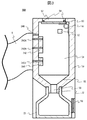
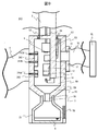
- FIG. 3 shows a cross-sectional view of the head cleaning unit 300 in this embodiment.
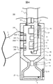
- 4 shows a cross-sectional view of the head cleaning unit 300 in which the print head 2 is inserted in this embodiment
- FIG. 5 shows a cross-section of the head cleaning unit main body 50 and the waste liquid container 23 provided in the head cleaning unit 300.
- 50 is a head cleaning unit body
- 23 is a waste liquid container
- 51 is a container connection part
- 52 is an insertion port
- 53 is a head cleaning unit lid part
- 54 is a seal part
- 55 is a solvent receiver
- 56 is a connection path
- 57 is a sensor (for a print head)
- 58 is a sensor (for a waste liquid container)
- 60 is a sealing plug.
- the head cleaning unit 300 includes an insertion port 52 into which the print head 2 can be inserted.
- the insertion port 52 does not mix the atmosphere inside the head cleaning unit 59 and the outside air when the print head 2 is not inserted.
- it is structured to be blocked by the head cleaning unit lid 53. That is, the head cleaning unit lid 53 is biased so as to close the insertion port 52 with a biasing member such as a torsion coil spring 61.
- the solvent receiver 55 is structured such that the solvent 6 supplied to the inside 59 of the head cleaning unit is supplied to the connection path 56 passing through the container connection part 51, and the container connection part 51 is supplied to the connection path 56.
- the solvent 6 is detachably connected to the waste liquid container 23 so as to be supplied to the waste liquid container 23 in the head cleaning unit 300 without leaking to the outside.
- the head cleaning unit 300 also includes a sensor (for print head) 57 that is a head detection unit that can detect whether the print head 2 is attached to the head cleaning unit 300, and the waste liquid container 23 is attached to the head cleaning unit 300.
- a sensor (for waste liquid container) 58 which is a container detecting means capable of detecting whether or not it has been, is provided.
- the positions of the sensors 57 and 58 are not limited to the illustrated positions, and may be arranged at positions where the print head 2 or the waste liquid container 23 can be detected.
- the sensor (for waste liquid container) 58 may be disposed at the position of the connection path 56. Further, sensors provided in the print head 2 and the waste liquid container 23 may be used.
- the head cleaning unit 300 in which the print head 2 is inserted is in close contact with the seal portion 54 and the print head 2 to prevent the cleaning liquid from flowing out from other than the connection path 56, and the atmosphere inside the head cleaning unit is outside air. And not to be mixed.
- the head cleaning unit lid 53 is an urging member so that when the print head 2 is removed from the insertion port 52, the insertion port 52 is blocked again so that the atmosphere inside the head cleaning unit 59 and the outside air are not mixed.
- the structure is energized.
- the cleaning nozzle ports 242A and 242B are provided in such positions and orientations that the solvent 6 can be brought into contact with the nozzle 8, the charging electrode 10, the ground deflection electrode 11, the plus deflection electrode 12, and the gutter 14 provided in the print head 2.
- the drying nozzle port 245 ⁇ / b> A removes the solvent 6 attached to the nozzle 8, the charging electrode 10, the ground deflection electrode 11, the plus deflection electrode 12, and the gutter 14 provided in the print head 2 by the air supplied from the drying nozzle 245. It is provided in a position and orientation that can be dried.
- the head cleaning unit 300 can supply the solvent 6 that has passed through the conduit (head cleaning unit) 5 from the cleaning nozzle ports 242A and 242B to the inside 59 of the head cleaning unit, thereby cleaning the print head 2.
- the solvent 6 used for cleaning is supplied from the solvent receiver 55 to the waste liquid container 23 through the connection path 56.
- the solvent 6 discharged from the cleaning nozzle ports 242A and 242B may be sucked from the nozzle 8 inside the print head 2 using the circulation path of the ink jet recording apparatus main body 1.
- the head cleaning unit 300 can supply the air that has passed through the conduit (head cleaning unit) 5 from the drying nozzle port 245 ⁇ / b> A to the head cleaning unit interior 59, so that the print head 2 can be dried.
- FIG. 5A shows a cross-sectional view of the head cleaning unit 300 in which the container connecting portion 51 of the head cleaning unit main body 50 and the waste liquid container 23 are connected
- FIG. 5B shows a state where the waste liquid container 23 is removed from the container connecting portion 51. Sectional drawing of the head washing
- the waste liquid container 23 includes the solvent 6
- the waste liquid container 23 includes a sealing plug 60 that can be attached to and detached from the waste liquid container 23, thereby blocking the outside air and the atmosphere inside the waste liquid container 23. It is possible to prevent the solvent 6 from flowing out of the waste liquid container 23 to the outside.
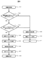
- FIG. 6 shows the operation flow of the head cleaning unit in this embodiment.
- step 101 a state in which the start of the function of the head cleaning unit 300 is instructed from the operation display unit 3 provided in the inkjet recording apparatus 400 is shown, and automatic cleaning is started.
- step 102 the waste liquid container 23 is connected to the container connecting portion 51 provided in the head cleaning unit 300 by the sensor (for waste liquid container) provided in the head cleaning unit 300 and the sensor provided in the waste liquid container 23. Determine whether or not. If the waste liquid container 23 is not connected to the container connection part 51, the process proceeds to step 109, and if the waste liquid container 23 is connected to the container connection part 51, the process proceeds to step 103.
- step 103 is the print head 2 inserted into the insertion port 52 provided in the head cleaning unit 300 by the sensor (for the print head) provided in the head cleaning unit 300 and the sensor provided in the print head 2.
- the process proceeds to step 109, and if the print head 2 is inserted into the insertion port 52, the process proceeds to step 104.
- step 104 the solvent 6 and the path in the ink jet recording apparatus 400 are used to operate the solenoid valve and the pump to discharge the solvent 6 from the cleaning nozzle 242 to clean the print head 2.
- the solvent 6 used for cleaning is the waste liquid.
- a cleaning sequence to be supplied to the container 23 is executed.
- step 105 executes a drying sequence in which the solenoid valve and pump in the ink jet recording apparatus 400 are operated to discharge air from the drying nozzle 245 and the print head 2 is dried.
- step 106 the operation of the electromagnetic valve and the pump in the ink jet recording apparatus 400 is stopped, and the automatic cleaning stop process is performed.
- Step 107 is an end message display process for indicating to the operator that the steps 104 to 106 have been normally performed.
- step 108 indicates a state in which the function of the head cleaning unit 300 has been completed normally, and the automatic cleaning ends.
- Step 109 indicates a state where it is determined in steps 102 and 103 that the function of the head cleaning unit 300 cannot be normally used, and automatic cleaning is interrupted.
- Step 110 is processing for indicating to the operator that the state is in step 109. For example, a message such as “The print head is not set in the cleaning unit” or “The waste liquid container is not set” is displayed. Is output. Step 111 shows a state where the processing of steps 109 to 110 is performed and stopped.
- step 104 and step 105 the operator may be able to select a sequence of a type in which the operations of the solenoid valve and the pump are different.
- the head cleaning unit having the insertion port into which the print head of the ink jet recording apparatus can be inserted, the path for supplying the cleaning liquid from the cleaning liquid container of the ink jet recording apparatus to the head cleaning unit, A nozzle for supplying the cleaning liquid to the inside and a container for collecting the cleaning liquid without flowing out of the cleaning liquid around the apparatus are provided.
- the cause of nozzle clogging can be removed by inserting the print head 2 into the head cleaning unit 300 provided in the inkjet recording apparatus 400, cleaning it with a solvent inside, and drying it. Further, it is possible to avoid the solvent from flowing out to the periphery of the apparatus by the seal portion 54 and the sealing plug 60. Furthermore, since the waste liquid container 23 whose inside is blocked from the outside air by the sealing plug 60 can be detached from the head cleaning unit 300 and can be moved to another place, the operator should perform the waste liquid treatment procedure according to the operator's equipment. Can do.
- the head cleaning unit 300 is described as including the head cleaning unit main body 50 and the waste liquid container 23.
- the waste liquid container 23 is provided separately from the head cleaning unit 300 as an external head cleaning unit 300.
- the head cleaning unit 300 may include an adapter that is attached to the inkjet recording apparatus 400 or other equipment.
- the head cleaning unit 300 has been described as having a cleaning nozzle and a drying nozzle. However, separate units for the cleaning nozzle and the drying nozzle may be used.
- FIG. 8 is a cross-sectional view of the head cleaning unit in this embodiment. 8, the same components as those in FIG. 5A are denoted by the same reference numerals, and the description thereof is omitted. 8 is different from FIG. 5A in that a waste liquid tank 74 connected to the waste liquid container 23 is provided.
- FIG. 8 is a sectional view of the waste liquid container 23 connected to the head cleaning unit 300 and the waste liquid tank 74 in a state connected to the waste liquid container 23.
- 71 and 72 are paths (for waste liquid)
- 73 is a path opening / closing cock
- 74 is a waste liquid tank
- 81 is waste liquid.
- the head cleaning unit 300 includes the waste liquid container 23 connected to the waste liquid tank 74 via the paths 71 and 72 in a state where it can be detached from the container connecting portion 51.
- the waste liquid container 23 includes a pipe that can discharge the internal waste liquid to the outside.
- the path 71 is connected to the waste liquid container 23, and the path 72 is connected to the waste liquid tank 74 in a removable state.
- the head cleaning unit 300 can supply the solvent 6 in the waste liquid container 23 to the waste liquid tank 74 through the path 71 and the path 72 by a free fall movement by opening the path opening / closing cock 73.
- the head cleaning unit 300 provided in the ink jet recording apparatus 400 can discard the solvent 6 in the waste liquid container 23 without removing the waste liquid container 23 from the container connection portion 51. Further, since the path 71 can be detached from the waste liquid container 23, the waste liquid container 23 can be removed from the container connection portion 51 as described in the first embodiment, and the disposal process can be performed. Therefore, the worker can perform the waste liquid treatment procedure according to the worker's equipment.
- FIG. 9 is a cross-sectional view of the head cleaning unit in this embodiment. 9, the same components as those in FIG. 4 are denoted by the same reference numerals, and the description thereof is omitted. 9 is different from FIG. 4 in that it has a configuration that can be connected to the external exhaust device 93.
- FIG. 9 is a cross-sectional view of the head cleaning unit 300 that can be connected to the external exhaust device 93.
- 91 is an exhaust port
- 92 is a conduit (exhaust)
- 93 is an external exhaust device.
- the head cleaning unit 300 has an exhaust port 91, and the exhaust port 91 can communicate the atmosphere inside the head cleaning unit 59 and the external exhaust device 93 via a conduit 92.
- the head cleaning unit 300 provided in the inkjet recording apparatus 400 discharges the atmosphere inside the head cleaning unit 59 to the outside from a path other than the exhaust path 217 of the inkjet recording apparatus main body 1. Can do. Therefore, the worker can perform an exhaust process in accordance with the worker's equipment.
- this invention is not limited to the above-mentioned Example, Various modifications are included.
- the above-described embodiments have been described in detail for easy understanding of the present invention, and are not necessarily limited to those having all the configurations described.
- a part of the configuration of a certain embodiment can be replaced with the configuration of another embodiment, and the configuration of another embodiment can be added to the configuration of a certain embodiment.
Landscapes
- Ink Jet (AREA)
Abstract
インクジェット記録装置周辺に洗浄液が流出することを回避し、洗浄に使用した後の洗浄液を密閉性の高い容器内に格納する印字ヘッド洗浄機能を有するインクジェット記録装置を提供することを目的とする。 上記目的を達成するために、印字対象物に印字をするためのインクが収容されるインク容器と洗浄液が収容された洗浄液容器を有する本体と、前記インク容器に接続され加圧供給されたインクが吐出されるノズルと印字に使用されるインク粒子を帯電させる帯電電極と前記帯電電極で帯電されたインク粒子を偏向させる偏向電極と印字に使用されないインク粒子を回収するガターを有する印字ヘッドと、を備えたインクジェット記録装置において、洗浄液が吐出される洗浄ノズルと印字ヘッドを挿入できる挿入口とを有するヘッド洗浄ユニットを備えた。
Description
本発明は、インクジェット記録装置のヘッド洗浄機能に関する。
本技術分野の背景技術として、特開2015-136934号公報(特許文献1)がある。特許文献1においては、インクジェット記録装置のヘッド洗浄方法として、ヘッド内部の洗浄ノズルから洗浄液をノズル吐出口に向けて噴出し洗浄を行う。そして、乾燥工程を行うことによりノズル詰まりの発生原因を除去する点が開示されている。
特許文献1の方法では、ヘッド内部の洗浄ノズルから洗浄液をノズル吐出口に向けて噴出した際、ヘッド外部に洗浄液が流出する可能性がある。
インクジェット記録装置は、食品、飲料水、薬品、化粧品など衛生面での管理が重要な生産ラインで使用されることが多い。そのため、インクジェット記録装置の内部や周辺の設備、床などに洗浄液やインクが流出しないことが求められている。
そこで、本発明の目的はインクジェット記録装置周辺に洗浄液が流出することを回避し、洗浄に使用した後の洗浄液を密閉性の高い容器内に格納する印字ヘッド洗浄機能を有するインクジェット記録装置を提供することである。
本発明は、上記背景技術に鑑み、その一例を挙げるならば、印字対象物に印字をするためのインクが収容されるインク容器と洗浄液が収容された洗浄液容器を有する本体と、前記インク容器に接続され加圧供給されたインクが吐出されるノズルと印字に使用されるインク粒子を帯電させる帯電電極と前記帯電電極で帯電されたインク粒子を偏向させる偏向電極と印字に使用されないインク粒子を回収するガターを有する印字ヘッドと、を備えたインクジェット記録装置において、洗浄液が吐出される洗浄ノズルと印字ヘッドを挿入できる挿入口とを有するヘッド洗浄ユニットを備えた。
本発明によれば、インクジェット記録装置周辺に洗浄液が流出することを回避し、ノズル詰まりの原因を除去できる印字ヘッド用のヘッド洗浄ユニットを備えたインクジェット記録装置を提供できる。
以下、図面を用いて本発明の実施例を説明する。
図1は、本実施例におけるインクジェット記録装置400の使用状態を示す斜視図である。図1において、1はインクジェット記録装置本体、2は印字ヘッド、3は操作表示部、4は導管(印字ヘッド)、5は導管(ヘッド洗浄ユニット)、300はヘッド洗浄ユニット(外部ユニット)である。インクジェット記録装置400は、インクジェット記録装置本体1に操作表示部3を備え、外部に印字ヘッド2とヘッド洗浄ユニット300を備え、インクジェット記録装置本体1と印字ヘッド2はおよそ3000mmの導管4にて接続されており、インクジェット記録装置本体1とヘッド洗浄ユニット300はおよそ3500mmの導管5にて接続されている。
また、13は数字や文字を印字される印字対象物、15は印字対象物13を搬送するベルトコンベア、16はベルトコンベア15の搬送距離を計測するロータリエンコーダ、17は印字センサ、18は印字ヘッドを任意の姿勢で固定するスタンド、19は印字ヘッド2をスタンド18に固定するための固定用冶具である。
インクジェット記録装置400は、例えば、食品や飲料などが生産される工場内の生産ラインに据え付けられ、インクジェット記録装置本体1は使用者が操作できる位置に設置され、印字ヘッド2はベルトコンベア15などの生産ライン上を給送される印字対象物13に近接できる位置に設置される。このとき印字ヘッド2に固定用冶具19を取り付けスタンド18に固定してもよい。ベルトコンベア15などの生産ライン上には給送速度に係わらず同じ幅で印字するために、給送速度に応じた信号をインクジェット記録装置400に出力するエンコーダ16や、印字対象物13を検出してインクジェット記録装置400に印字を指示する信号を出力する印字センサ17が設置されていて、それぞれはインクジェット記録装置本体1内の図示しない制御部に接続されている。エンコーダ16や印字センサ17からの信号に応じて制御部がノズルから吐出されるインク粒子への帯電量や帯電タイミングを制御し、印字対象物13が印字ヘッド2近傍を通過する間に帯電、偏向されたインク粒子を印字対象物13へ付着させて印字を行うようになっている。
ヘッド洗浄ユニット300は、印字ヘッド2の近くに設置される。このとき、ヘッド洗浄ユニット300の設置の自由度を持たせるために導管5は導管4よりも長くなっている。印字ヘッドを洗浄及び乾燥させる際に印字ヘッド2をヘッド洗浄ユニット300に設置する。すると、導管5を通りインクジェット記録装置本体1からヘッド洗浄ユニット300に送られた空気及び溶剤(以降、洗浄液とも言う)がヘッド洗浄ユニット内のノズルから吐出し、印字ヘッド2を洗浄及び乾燥するようになっている。
次に、インクジェット記録装置の動作原理について図7を用いて説明する。図7において、20は主インク容器、7Aはインク、24はインクを加圧し、送り出すポンプ(供給用)、9は電圧を印加すると所定の周波数で振動する電歪素子、8はインクを吐出するノズル、7Bはインク柱である。10はインク粒子に帯電させる帯電電極、7Cはインク粒子で、11はグランド偏向電極、12はプラス偏向電極、13は印字される印字対象物、14は印字しないインク粒子を回収するガターである。
主インク容器20内のインク7Aはポンプ(供給用)24に吸引、加圧されてインク柱7Bとなってノズル8から吐出される。ノズル8には、電歪素子9が備えられており、インクに所定の周波数で振動を加えてノズル8から吐出されるインク柱7Bを粒子化するようになっている。これにより生成されるインク粒子7Cの数は,電歪素子9に印加する励振電圧の周波数により決定され、その周波数と同数となる。インク粒子7Cは、印字情報に対応した大きさの電圧を帯電電極10にて印加することで電荷を与えられるようになっている。
帯電電極10で帯電させられたインク粒子7Cは、グランド偏向電極11とプラス偏向電極12間の電界中を飛翔する。偏向電界は、1~7kVの高電圧が印加されたプラス偏向電極12と設置されたグランド偏向電極11との間に形成されており、帯電したインク粒子7Cは、その帯電量に比例した力を受けて偏向し、印字対象物13へ向かって飛翔して着弾する。
その際、インク粒子7Cは帯電量に応じて偏向方向の着弾位置は変化し、さらに偏向方向と直交する方向に生産ラインが印字対象物13を移動させることで、偏向方向と直交した方向にも粒子を着弾させることが可能となり、複数の着弾インク粒子7Dによって文字を構成し印字を行う。印字に使用されなかったインク粒子7Cはプラス偏向電極12間を直線的に飛翔して、ガター14により捕捉された後に、ポンプ(回収用)25で吸引されて主インク容器20に回収される。
次に、本実施例におけるインクジェット記録装置400のインク供給経路について説明する。図2は、本実施例におけるインクジェット記録装置の経路構成を示す図である。図2において、インクジェット記録装置本体1には、循環するインク7Aを保持する主インク容器20が備えられており、主インク容器20には、主インク容器20内の液体が内部に保持されるのに適正な量である基準液面レベルに達しているか否かを検知する液面センサ46が備えられている。
主インク容器20は、主インク容器20内のインク7Aの粘度を把握するために、経路201を介して粘度測定器43に接続されている。粘度測定器43は経路202を介して経路の開閉を行う電磁弁(供給用)34に接続されており、電磁弁(供給用)34は経路203を介してインク7Aを吸引、圧送するために使用されるポンプ(供給用)24に接続されている。そして、ポンプ(供給用)24は経路204を介してインク7A中に混入している異物を除去するフィルタ(供給用)28に接続されている。
フィルタ(供給用)28は、経路205を介してポンプ(供給用)24から圧送されたインク7Aを印字するために適正な圧力に調整する調圧弁33に接続されており、調圧弁33は経路206を介してノズル8に供給されるインク7Aの圧力を測定する圧力センサ31が備えられている。圧力センサ31は、導管4内を通る経路207を介してノズル8にインク7Aを供給するかどうかを制御するための切替弁42に接続されている。
切替弁42は、経路209を介して、インク7Aを吐出する吐出口を備えたノズル8に接続されている。なお、切替弁42は三方型電磁弁であり、切替弁42にはインク供給用の経路207と洗浄用の経路237が接続されており、ノズル8にインクと溶剤の供給を切り替えることができる。ノズル8の吐出口の直進方向には、インク粒子7Cに所定の電荷量を付加するための帯電電極10、印字に使用するインク粒子7Cを偏向させるための偏向電極12、及び、印字に使用されないために帯電、偏向されずに直進的に飛翔するインク粒子7Cを捕捉するためのガター14が配置されている。
次に、インク回収経路について説明する。図2において、ガター14は、導管4内を通る経路212を介してインクジェット記録装置本体1内に配置されているインク中に混入している異物を除去するフィルタ(回収用)30と接続されており、フィルタ(回収用)29は、経路213を介して経路の開閉を行う電磁弁(回収用)35に接続されている。
電磁弁(回収用)35は経路214を介してガター14により捕捉されたインク粒子7Cを吸引するポンプ(回収用)25と接続されている。ポンプ(回収用)25は、経路215及び経路216を介して主インク容器20と接続されている。また、主インク容器20は、排気経路217と接続されていて、排気経路217はインクジェット記録装置本体1の外部と連通した構成をとっている。
次に、インク補給経路について説明する。図2において、インクジェット記録装置本体1には、補充用のインクを保持する補助インク容器21が備えられており、補助インク容器21は、経路221を介して経路の開閉を行う電磁弁36に接続されている。そして、電磁弁36は経路222を介して、インク供給経路203と接続された合流経路223に接続されている。
次に、インク循環経路について説明する。図2において、印字ヘッド2内に備えられたノズル8には、インク供給用の経路207の他に導管4内を通る経路225を介してインクジェット記録装置本体1内に備えられ、流路の開閉を行う電磁弁37に接続されている。電磁弁37は、経路226を介してノズル8からのインクの吸引を行うポンプ(循環用)26に接続されている。そして、ポンプ(循環用)26は経路227を介して、インク回収経路215に接続された合流経路228に接続された構成となっている。
次に、溶剤補給経路について説明する。図2において、インクジェット記録装置本体1には、溶剤補給用の溶剤6を保持する溶剤容器22が備えられており、溶剤容器22は、経路231を介して溶剤6を吸引、圧送するために使用されるポンプ(溶剤用)27に接続されている。ポンプ(溶剤用)27は、経路232及び分岐経路235を介して流路の開閉を行うために電磁弁(溶剤補給用)38に接続されており、電磁弁(溶剤補給用)38は、経路233を介して主インク容器20と接続されている。
次に、洗浄経路について説明する。図2において、ポンプ(溶剤用)27は、経路232にある分岐経路235及び経路236を介して、流路の開閉を行うための電磁弁(洗浄用)39に接続されている。そして、電磁弁(洗浄用)39は、経路237を介してノズル8に洗浄のための溶剤を送るかどうかを制御するための切替弁42に接続された構成となっている。
次に、ヘッド洗浄ユニット経路について説明する。図2において、経路236は分岐経路238及び経路239を介して流路の開閉を行うために電磁弁(ヘッド洗浄ユニット用)40に接続されており、電磁弁(ヘッド洗浄ユニット用)40は経路240を介してインクジェット記録装置本体1内に配置されている溶剤中に混入している異物を除去するフィルタ(ヘッド洗浄ユニット用)30と接続されている。フィルタ(ヘッド洗浄ユニット用)30は経路241を介して洗浄ノズル242に接続されており、洗浄ノズル242は溶剤6を吐出する洗浄ノズル口242A及び242Bを備えた構成となっている。また、この洗浄ノズル口の数は単数の場合や多数の場合もある。
次に、乾燥経路について説明する。図2において、経路243は空気を供給する外部に備え付けられた空気圧縮機に接続されている。または、インクジェット記録装置本体1内部に備えられた空気を供給するポンプに接続されている。経路243は経路の開閉を行うための電磁弁(空気供給用)41に接続されており、電磁弁(空気供給用)41は経路244を介して乾燥ノズル(エアノズル)245に接続されている。乾燥ノズル245は空気を吐出する乾燥ノズル口245Aを備えている。また、この乾燥ノズル口の数は単数の場合や多数の場合もある。
次に、廃液経路について説明する。図2において、洗浄ノズル口242A~Bから吐出した溶剤6は容器接続部51を介し、ヘッド洗浄ユニット300内の廃液容器23に供給される。
次に、ヘッド洗浄ユニット300の排気経路について説明する。図2において、ヘッド洗浄ユニット内部59と連通した構成の経路246は導管5を通りインクジェット記録装置400のインクジェット記録装置本体1内にある合流経路247を介して排気経路217と接続されている。
図3は、本実施例におけるヘッド洗浄ユニット300の断面図を示す。また、図4は、本実施例における印字ヘッド2が挿入されたヘッド洗浄ユニット300の断面図を示し、図5は、ヘッド洗浄ユニット300に備えられたヘッド洗浄ユニット本体50と廃液容器23の断面図である。
図3~図5A、5Bにおいて、50はヘッド洗浄ユニット本体、23は廃液容器、51は容器接続部、52は挿入口、53はヘッド洗浄ユニット蓋部、54はシール部、55は溶剤受け、56は接続経路、57はセンサ(印字ヘッド用)、58はセンサ(廃液容器用)、60は封止栓である。
まず、ヘッド洗浄ユニット300の使用状態について図3~図5A、5Bを用いて説明する。図3において、ヘッド洗浄ユニット300は、印字ヘッド2が挿入できる挿入口52を備えており、挿入口52は印字ヘッド2が挿入されていない場合にヘッド洗浄ユニット内部59の雰囲気と外気が混ざらないようにヘッド洗浄ユニット蓋部53によって遮断される構造になっている。すなわち、ヘッド洗浄ユニット蓋部53は、ねじりコイルバネ61のような付勢部材で挿入口52を塞ぐように付勢されている。また、溶剤受け55はヘッド洗浄ユニット内部59に供給された溶剤6が容器接続部51を通る接続経路56に供給されるような構造になっており、容器接続部51は、接続経路56に供給された溶剤6が外部に漏れることなくヘッド洗浄ユニット300内の廃液容器23に供給されるように廃液容器23と着脱可能な状態で接続されている。また、ヘッド洗浄ユニット300は、ヘッド洗浄ユニット300に印字ヘッド2が取り付けられたかどうかを検知できるヘッド検出手段であるセンサ(印字ヘッド用)57を備え、ヘッド洗浄ユニット300に廃液容器23が取り付けられたかどうかを検知できる容器検出手段であるセンサ(廃液容器用)58を備えている。なお、センサ57、58の位置は、図示した位置に限定されるものではなく、印字ヘッド2または廃液容器23が検知できる位置に配置すればよい。例えば、センサ(廃液容器用)58は、接続経路56の位置に配置してもよい。また、印字ヘッド2及び廃液容器23に備えられたセンサを使用してもよい。
図4において、印字ヘッド2が挿入されたヘッド洗浄ユニット300は、シール部54と印字ヘッド2が密着し、接続経路56以外から洗浄液が流出することを回避し、ヘッド洗浄ユニット内部の雰囲気が外気と混ざらないようになっている。また、ヘッド洗浄ユニット蓋部53は、印字ヘッド2を挿入口52から外した際に、ヘッド洗浄ユニット内部59の雰囲気と外気が混ざらないように再び挿入口52を遮断するように付勢部材で付勢する構造になっている。また、洗浄ノズル口242A及び242Bは、印字ヘッド2に備えられたノズル8、帯電電極10、グランド偏向電極11、プラス偏向電極12、ガター14に溶剤6を接触させられるような位置や向きで備えられている。さらに、乾燥ノズル口245Aは、乾燥ノズル245から供給される空気によって、印字ヘッド2に備えられたノズル8、帯電電極10、グランド偏向電極11、プラス偏向電極12、ガター14に付着した溶剤6を乾燥できるような位置や向きで備えられている。
ヘッド洗浄ユニット300は、導管(ヘッド洗浄ユニット)5を通った溶剤6を洗浄ノズル口242A及び242Bからヘッド洗浄ユニット内部59に供給でき、印字ヘッド2を洗浄することができる。洗浄に使用した溶剤6は溶剤受け55から接続経路56を通り廃液容器23に供給される。このとき、洗浄ノズル口242A及び242Bから吐出された溶剤6をインクジェット記録装置本体1の循環経路を使い印字ヘッド2内部のノズル8から吸引してもよい。また、ヘッド洗浄ユニット300は導管(ヘッド洗浄ユニット)5を通った空気を乾燥ノズル口245Aからヘッド洗浄ユニット内部59に供給でき、印字ヘッド2を乾燥することができる。
図5Aは、ヘッド洗浄ユニット本体50の容器接続部51と廃液容器23が接続状態にあるヘッド洗浄ユニット300の断面図を示し、図5Bは、容器接続部51から廃液容器23が外された状態にあるヘッド洗浄ユニット300の断面図を示す。図5Bにおいて、廃液容器23が溶剤6を備えていた場合、廃液容器23は、廃液容器23に着脱可能な封止栓60を備えることによって、外気と廃液容器23内部の雰囲気を遮断することができ、廃液容器23から外部に溶剤6が流出することを回避できる。
本実施例におけるヘッド洗浄ユニットの動作フローを図6に示す。図6において、まずステップ101において、インクジェット記録装置400に備えられた操作表示部3からヘッド洗浄ユニット300の機能の開始を指示した状態を示し、自動洗浄を開始する。
次にステップ102は、ヘッド洗浄ユニット300に備えられたセンサ(廃液容器用)及び廃液容器23に備えられたセンサによって廃液容器23がヘッド洗浄ユニット300に備えられた容器接続部51と接続されているかどうかを判断する。廃液容器23が容器接続部51と接続されていない場合はステップ109に進み、廃液容器23が容器接続部51と接続されていた場合はステップ103に進む。
次にステップ103は、ヘッド洗浄ユニット300に備えられたセンサ(印字ヘッド用)及び印字ヘッド2に備えられたセンサによって印字ヘッド2がヘッド洗浄ユニット300に備えられた挿入口52に挿入されているかどうかを判断する。印字ヘッド2が挿入口52に挿入されていない場合はステップ109に進み、印字ヘッド2が挿入口52に挿入されていた場合はステップ104に進む。
ステップ104は、インクジェット記録装置400内の溶剤6や経路を使い、電磁弁、ポンプを動作させ洗浄ノズル242から溶剤6を吐出させ、印字ヘッド2を洗浄し、洗浄に使用された溶剤6は廃液容器23に供給する洗浄シーケンスを実行する。
次にステップ105は、インクジェット記録装置400内の電磁弁、ポンプを動作させ乾燥ノズル245から空気を吐出させ、印字ヘッド2を乾燥する乾燥シーケンスを実行する。
次にステップ106は、インクジェット記録装置400内の電磁弁、ポンプの動作を停止させ、自動洗浄の停止処理を行う。
ステップ107は、ステップ104~106のステップが正常に行われたことを作業者に示す終了メッセージ表示処理である。
最後にステップ108は、ヘッド洗浄ユニット300の機能を正常に終了できた状態を示し、自動洗浄を終了する。
ステップ109はステップ102及びステップ103においてヘッド洗浄ユニット300の機能を正常に使用できる状態でないと判断された状態を示し、自動洗浄の中断処理を行なう。
ステップ110はステップ109の状態にあることを作業者に示す処理であり、例えば、「印字ヘッドが洗浄ユニットにセットされていません。」または「廃液容器がセットされていません。」などのメッセージを出力する。ステップ111はステップ109~110の処理をし、停止した状態を示す。
なお、ステップ104及びステップ105において、電磁弁、ポンプの動作が異なる種類のシーケンスを作業者が選択できるようにしてもよい。
以上のように、本実施例は、インクジェット記録装置の印字ヘッドを挿入できる挿入口を有するヘッド洗浄ユニットと、インクジェット記録装置の洗浄液容器からヘッド洗浄ユニットに洗浄液を供給する経路と、ヘッド洗浄ユニットの内側に洗浄液を供給するノズルと、装置周辺に洗浄液が流出することなく洗浄液を回収する容器を備える。
これにより、インクジェット記録装置400に備えられたヘッド洗浄ユニット300に印字ヘッド2を挿入し、内部で溶剤によって洗浄し、乾燥させることによって、ノズル詰まりの発生原因を除去することができる。また、シール部54及び封止栓60によって装置周辺に溶剤が流出することを回避できる。さらに、封止栓60によって内部が外気と遮断された廃液容器23はヘッド洗浄ユニット300から取り外し可能で別の場所に移動できるため、作業者は作業者の設備に合わせた廃液処理手順をすることができる。
なお、以上の説明では、ヘッド洗浄ユニット300はヘッド洗浄ユニット本体50と廃液容器23を備えているとして説明したが、廃液容器23はヘッド洗浄ユニット300と別体としてヘッド洗浄ユニット300の外付けとしてもよい。また、ヘッド洗浄ユニット300は、インクジェット記録装置400やその他の設備に取り付けられるアダプタを備えていてもよい。
また、以上の説明では、ヘッド洗浄ユニット300は洗浄ノズルと乾燥ノズルを有しているとして説明したが、洗浄ノズル用と乾燥ノズル用の別々のユニットとしてもよい。
図8は、本実施例におけるヘッド洗浄ユニットの断面図である。図8において、図5Aと同じ構成については同じ符号を付し、その説明は省略する。図8において図5Aと異なる点は、廃液容器23と接続された廃液タンク74を有する点である。
図8はヘッド洗浄ユニット300に接続されている廃液容器23と廃液容器23と接続された状態の廃液タンク74の断面図を示す。図8において、71、72は経路(廃液用)、73は経路開閉コック、74は廃液タンク、81は廃液を示す。
ヘッド洗浄ユニット300は、経路71及び72を介して廃液タンク74と接続された廃液容器23を容器接続部51と取り外し可能な状態で備えている。言い換えれば、廃液容器23は、内部の廃液を外部に排出できる配管を備えている。経路71は廃液容器23と、経路72は廃液タンク74とそれぞれ取り外し可能な状態で接続されている。
ヘッド洗浄ユニット300は、廃液容器23内の溶剤6を、経路開閉コック73を開けることによって自由落下運動で経路71及び経路72を介し廃液タンク74に供給できる。
このように、本実施例によれば、インクジェット記録装置400に備えられたヘッド洗浄ユニット300は廃液容器23を容器接続部51から取り外すことなく廃液容器23内の溶剤6を廃棄することができる。また、経路71は廃液容器23と取り外しが可能なため、実施例1で述べたように容器接続部51から廃液容器23を外し、廃棄処理を行うこともできる。そのため、作業者は作業者の設備に合わせた廃液処理手順をすることができる。
図9は、本実施例におけるヘッド洗浄ユニットの断面図である。図9において、図4と同じ構成については同じ符号を付し、その説明は省略する。図9において図4と異なる点は、外部排気装置93と接続可能な構成を有している点である。
図9は外部排気装置93と接続可能な構成のヘッド洗浄ユニット300の断面図を示す。図9において91は排気口、92は導管(排気)、93は外部排気装置を示す。ヘッド洗浄ユニット300は排気口91を有し、排気口91は導管92を介しヘッド洗浄ユニット内部59の雰囲気と外部排気装置93を連通させることができる。
このように、本実施例によれば、インクジェット記録装置400に備えられたヘッド洗浄ユニット300はインクジェット記録装置本体1の排気経路217以外の経路からヘッド洗浄ユニット内部59の雰囲気を外部へ排出することができる。そのため、作業者は作業者の設備に合わせた排気処理を行うことができる。
なお、本発明は上記した実施例に限定されるものではなく、様々な変形例が含まれる。例えば、上記した実施例は本発明を分かりやすく説明するために詳細に説明したものであり、必ずしも説明した全ての構成を備えるものに限定されるものではない。また、ある実施例の構成の一部を他の実施例の構成に置き換えることが可能であり、また、ある実施例の構成に他の実施例の構成を加えることも可能である。また、各実施例の構成の一部について、他の構成の追加・削除・置換をすることが可能である。
1:インクジェット記録装置本体、2:印字ヘッド、5:導管(ヘッド洗浄ユニット)、6:溶剤、8:ノズル、14:ガター、20:主インク容器、21:補助インク容器、22:溶剤容器、23:廃液容器、30:フィルタ(ヘッド洗浄ユニット用)、38:電磁弁(溶剤補給用)、39:電磁弁(洗浄用)、40:電磁弁(ヘッド洗浄ユニット用)、41:電磁弁(空気供給用)、50:ヘッド洗浄ユニット本体、51:容器接続部、52:挿入口、53:ヘッド洗浄ユニット蓋部、54:シール部、55:溶剤受け、56:接続経路、57:センサ(印字ヘッド用)、58:センサ(廃液容器用)、59:ヘッド洗浄ユニット内部、60:封止栓、61:ねじりコイルバネ、71、72:経路(廃液用)、73:経路開閉コック、74:廃液タンク、81:廃液、91:排気口、92:導管(排気)、93:外部排気装置、236~237:経路(洗浄用)、239~241:経路(ヘッド洗浄ユニット用)、242:洗浄ノズル、242A~B:洗浄ノズル口、243~244:経路(空気供給用)245:乾燥ノズル、245A:乾燥ノズル口、246:経路(排気用)、300:ヘッド洗浄ユニット、400:インクジェット記録装置
Claims (16)
- 印字対象物に印字をするためのインクが収容されるインク容器と洗浄液が収容された洗浄液容器を有する本体と、前記インク容器に接続され加圧供給されたインクが吐出されるノズルと印字に使用されるインク粒子を帯電させる帯電電極と前記帯電電極で帯電されたインク粒子を偏向させる偏向電極と印字に使用されないインク粒子を回収するガターを有する印字ヘッドと、を備えたインクジェット記録装置において、
前記洗浄液が吐出される洗浄ノズルと前記印字ヘッドを挿入できる挿入口とを有するヘッド洗浄ユニットを備えたことを特徴とするインクジェット記録装置。 - 請求項1に記載のインクジェット記録装置であって、
前記本体と前記ヘッド洗浄ユニットは別体として設けられていることを特徴とするインクジェット記録装置。 - 請求項1または2に記載のインクジェット記録装置であって、
前記ヘッド洗浄ユニットは、前記本体と導管で接続されていることを特徴とするインクジェット記録装置。 - 請求項1~3の何れか1項に記載のインクジェット記録装置であって、
前記洗浄液容器は、前記洗浄ノズルと洗浄経路で接続されていることを特徴とするインクジェット記録装置。 - 請求項1~4の何れか1項に記載のインクジェット記録装置であって、
前記ヘッド洗浄ユニットは、洗浄に使用した前記洗浄液が収容される廃液容器を接続可能にする容器接続部を有することを特徴とするインクジェット記録装置。 - 請求項1~5の何れか1項に記載のインクジェット記録装置であって、
前記ヘッド洗浄ユニットは、前記挿入口に前記印字ヘッドが挿入されたかどうかを検出するヘッド検出手段が設置されていることを特徴とするインクジェット記録装置。 - 請求項5に記載のインクジェット記録装置であって、
前記ヘッド洗浄ユニットは、前記廃液容器が前記容器接続部に接続されたかどうかを検出する容器検出手段を有することを特徴とするインクジェット記録装置。 - 請求項1~7の何れか1項に記載のインクジェット記録装置であって、
前記挿入口は、前記ヘッド洗浄ユニット内部の雰囲気と外気を遮断するシール部を有することを特徴とするインクジェット記録装置。 - 請求項1~8の何れか1項に記載のインクジェット記録装置であって、
前記ヘッド洗浄ユニットは、空気が吐出されるエアノズルを有することを特徴とするインクジェット記録装置。 - 印字対象物に印字をするためのインクが収容されるインク容器と洗浄液が収容された洗浄液容器を有する本体と、前記インク容器に接続され加圧供給されたインクが吐出されるノズルと印字に使用されるインク粒子を帯電させる帯電電極と前記帯電電極で帯電されたインク粒子を偏向させる偏向電極と印字に使用されないインク粒子を回収するガターを有する印字ヘッドと、を備えたインクジェット記録装置において、
空気が吐出されるエアノズルと前記印字ヘッドを挿入できる挿入口とを有する外部ユニットを備えたことを特徴とするインクジェット記録装置。 - 請求項10に記載のインクジェット記録装置であって、
前記本体と前記外部ユニットは別体として設けられていることを特徴とするインクジェット記録装置。 - 請求項10または11に記載のインクジェット記録装置であって、
前記外部ユニットは、前記本体と導管で接続されていることを特徴とするインクジェット記録装置。 - 請求項9~12の何れか1項に記載のインクジェット記録装置であって、
前記エアノズルは、空気を送るためのエアポンプと接続されていることを特徴とするインクジェット記録装置。 - 請求項9~12の何れか1項に記載のインクジェット記録装置であって、
前記エアノズルは、空気を送るための外部空気圧縮機と接続可能である経路に接続されていることを特徴とするインクジェット記録装置。 - 請求項3または12に記載のインクジェット記録装置であって、
前記本体は、前記印字ヘッドとヘッド導管で接続されており、
前記導管は、前記ヘッド導管よりも長いことを特徴とするインクジェット記録装置。 - 請求項5に記載のインクジェット記録装置であって、
前記廃液容器は、内部の廃液を外部に排出できる配管を備えることを特徴とするインクジェット記録装置。
Priority Applications (10)
| Application Number | Priority Date | Filing Date | Title |
|---|---|---|---|
| JP2020523503A JP7146912B2 (ja) | 2018-06-06 | 2019-01-24 | インクジェット記録装置 |
| EP23180606.8A EP4241999A3 (en) | 2018-06-06 | 2019-01-24 | Inkjet recording device |
| EP19815390.0A EP3804995B1 (en) | 2018-06-06 | 2019-01-24 | Inkjet recording device |
| CN201980008323.6A CN111601719B (zh) | 2018-06-06 | 2019-01-24 | 喷墨记录装置 |
| CN202211546241.7A CN115782405A (zh) | 2018-06-06 | 2019-01-24 | 喷墨记录装置和头清洗装置 |
| US15/734,018 US20210229446A1 (en) | 2018-06-06 | 2019-01-24 | Inkjet Recording Device |
| JP2022113076A JP7384969B2 (ja) | 2018-06-06 | 2022-07-14 | インクジェット記録装置 |
| US18/360,985 US20230364913A1 (en) | 2018-06-06 | 2023-07-28 | Inkjet Recording Device |
| JP2023191257A JP2023184705A (ja) | 2018-06-06 | 2023-11-09 | インクジェット記録装置 |
| JP2023191252A JP2023184704A (ja) | 2018-06-06 | 2023-11-09 | インクジェット記録装置 |
Applications Claiming Priority (2)
| Application Number | Priority Date | Filing Date | Title |
|---|---|---|---|
| JP2018-108347 | 2018-06-06 | ||
| JP2018108347 | 2018-06-06 |
Related Child Applications (2)
| Application Number | Title | Priority Date | Filing Date |
|---|---|---|---|
| US15/734,018 A-371-Of-International US20210229446A1 (en) | 2018-06-06 | 2019-01-24 | Inkjet Recording Device |
| US18/360,985 Continuation US20230364913A1 (en) | 2018-06-06 | 2023-07-28 | Inkjet Recording Device |
Publications (1)
| Publication Number | Publication Date |
|---|---|
| WO2019234965A1 true WO2019234965A1 (ja) | 2019-12-12 |
Family
ID=68770110
Family Applications (1)
| Application Number | Title | Priority Date | Filing Date |
|---|---|---|---|
| PCT/JP2019/002205 WO2019234965A1 (ja) | 2018-06-06 | 2019-01-24 | インクジェット記録装置 |
Country Status (5)
| Country | Link |
|---|---|
| US (2) | US20210229446A1 (ja) |
| EP (2) | EP3804995B1 (ja) |
| JP (4) | JP7146912B2 (ja) |
| CN (2) | CN115782405A (ja) |
| WO (1) | WO2019234965A1 (ja) |
Cited By (6)
| Publication number | Priority date | Publication date | Assignee | Title |
|---|---|---|---|---|
| JP2021014040A (ja) * | 2019-07-10 | 2021-02-12 | 株式会社日立産機システム | インクジェット記録装置およびインクジェット記録装置の制御方法 |
| WO2021199506A1 (ja) | 2020-03-30 | 2021-10-07 | 株式会社日立産機システム | インクジェット記録装置およびインクジェット記録装置の洗浄方法 |
| JPWO2022097212A1 (ja) * | 2020-11-04 | 2022-05-12 | ||
| JP7365219B2 (ja) | 2019-12-12 | 2023-10-19 | 株式会社キーエンス | インクジェット記録システム |
| JP7365218B2 (ja) | 2019-12-12 | 2023-10-19 | 株式会社キーエンス | インクジェット記録システム |
| JP7366725B2 (ja) | 2019-12-12 | 2023-10-23 | 株式会社キーエンス | インクジェット記録システム |
Families Citing this family (5)
| Publication number | Priority date | Publication date | Assignee | Title |
|---|---|---|---|---|
| JP7280677B2 (ja) * | 2018-09-27 | 2023-05-24 | 株式会社日立産機システム | インクジェット記録装置 |
| JP7356780B2 (ja) * | 2019-12-12 | 2023-10-05 | 株式会社キーエンス | インクジェット記録システム |
| CN113334944A (zh) * | 2021-04-28 | 2021-09-03 | 绍兴蓝之印家纺有限公司 | 一种纸板箱多面喷码装置 |
| US20220379620A1 (en) * | 2021-05-26 | 2022-12-01 | Seiko Epson Corporation | Discharged liquid container and recording apparatus |
| JP2023128091A (ja) * | 2022-03-02 | 2023-09-14 | 株式会社ミヤコシ | 分配タンク |
Citations (9)
| Publication number | Priority date | Publication date | Assignee | Title |
|---|---|---|---|---|
| JPS61193857A (ja) * | 1985-02-22 | 1986-08-28 | Nec Corp | インクジエツトプリンタのヘツドクリ−ニング方法 |
| JPH0439055A (ja) * | 1990-06-05 | 1992-02-10 | Inax Corp | インクジェット式プリンタヘッドのノズル洗浄方法 |
| US5183066A (en) * | 1991-04-02 | 1993-02-02 | General Dynamics Corp., Air Defense Systems Division | Spray nozzle cleaning apparatus and method |
| JPH0780385A (ja) * | 1993-09-10 | 1995-03-28 | Hirata Corp | 塗布ヘッド洗浄装置及び塗布ヘッドの洗浄方法 |
| JPH09262518A (ja) * | 1996-03-29 | 1997-10-07 | Tokico Ltd | 塗装ガン洗浄装置 |
| JP2000229419A (ja) * | 1999-02-09 | 2000-08-22 | Keyence Corp | インクジェット記録装置 |
| JP2010194829A (ja) * | 2009-02-24 | 2010-09-09 | Ricoh Co Ltd | 画像形成装置 |
| JP2013056520A (ja) * | 2011-09-09 | 2013-03-28 | Mimaki Engineering Co Ltd | インクジェットプリンタ、インク回収部材、及びインク回収方法 |
| JP2015136934A (ja) | 2014-01-24 | 2015-07-30 | 株式会社キーエンス | インクジェット記録装置及びそのヘッド洗浄方法 |
Family Cites Families (9)
| Publication number | Priority date | Publication date | Assignee | Title |
|---|---|---|---|---|
| JP3403010B2 (ja) * | 1996-07-12 | 2003-05-06 | キヤノン株式会社 | 液体吐出ヘッド |
| CN1287106C (zh) * | 2002-04-12 | 2006-11-29 | 精工爱普生株式会社 | 阀门装置 |
| JP4629465B2 (ja) * | 2005-03-11 | 2011-02-09 | 株式会社日立産機システム | インクジェット記録装置 |
| US20070252863A1 (en) * | 2006-04-29 | 2007-11-01 | Lizhong Sun | Methods and apparatus for maintaining inkjet print heads using parking structures with spray mechanisms |
| FR2913632A1 (fr) * | 2007-03-14 | 2008-09-19 | Imaje Sa Sa | Dispositif d'impression a jet d'encre a injecteur d'air, injecteur d'air et tete d'impression grande largeur associes |
| KR101446296B1 (ko) * | 2007-04-11 | 2014-10-01 | 무사시 엔지니어링 가부시키가이샤 | 잉크젯 토출 헤드 및 그 장치 |
| JP6932476B2 (ja) * | 2015-04-14 | 2021-09-08 | キヤノン株式会社 | プリント装置 |
| CN106808799B (zh) * | 2017-02-24 | 2018-08-28 | 广州易达包装设备有限公司 | 一种非接触式喷码机的喷头及其清洗方法 |
| CN207403377U (zh) * | 2017-10-28 | 2018-05-25 | 青岛三皆益喷码技术有限公司 | 一种喷码机喷头 |
-
2019
- 2019-01-24 WO PCT/JP2019/002205 patent/WO2019234965A1/ja unknown
- 2019-01-24 CN CN202211546241.7A patent/CN115782405A/zh active Pending
- 2019-01-24 CN CN201980008323.6A patent/CN111601719B/zh active Active
- 2019-01-24 US US15/734,018 patent/US20210229446A1/en not_active Abandoned
- 2019-01-24 JP JP2020523503A patent/JP7146912B2/ja active Active
- 2019-01-24 EP EP19815390.0A patent/EP3804995B1/en active Active
- 2019-01-24 EP EP23180606.8A patent/EP4241999A3/en active Pending
-
2022
- 2022-07-14 JP JP2022113076A patent/JP7384969B2/ja active Active
-
2023
- 2023-07-28 US US18/360,985 patent/US20230364913A1/en active Pending
- 2023-11-09 JP JP2023191257A patent/JP2023184705A/ja active Pending
- 2023-11-09 JP JP2023191252A patent/JP2023184704A/ja active Pending
Patent Citations (9)
| Publication number | Priority date | Publication date | Assignee | Title |
|---|---|---|---|---|
| JPS61193857A (ja) * | 1985-02-22 | 1986-08-28 | Nec Corp | インクジエツトプリンタのヘツドクリ−ニング方法 |
| JPH0439055A (ja) * | 1990-06-05 | 1992-02-10 | Inax Corp | インクジェット式プリンタヘッドのノズル洗浄方法 |
| US5183066A (en) * | 1991-04-02 | 1993-02-02 | General Dynamics Corp., Air Defense Systems Division | Spray nozzle cleaning apparatus and method |
| JPH0780385A (ja) * | 1993-09-10 | 1995-03-28 | Hirata Corp | 塗布ヘッド洗浄装置及び塗布ヘッドの洗浄方法 |
| JPH09262518A (ja) * | 1996-03-29 | 1997-10-07 | Tokico Ltd | 塗装ガン洗浄装置 |
| JP2000229419A (ja) * | 1999-02-09 | 2000-08-22 | Keyence Corp | インクジェット記録装置 |
| JP2010194829A (ja) * | 2009-02-24 | 2010-09-09 | Ricoh Co Ltd | 画像形成装置 |
| JP2013056520A (ja) * | 2011-09-09 | 2013-03-28 | Mimaki Engineering Co Ltd | インクジェットプリンタ、インク回収部材、及びインク回収方法 |
| JP2015136934A (ja) | 2014-01-24 | 2015-07-30 | 株式会社キーエンス | インクジェット記録装置及びそのヘッド洗浄方法 |
Cited By (14)
| Publication number | Priority date | Publication date | Assignee | Title |
|---|---|---|---|---|
| JP2021014040A (ja) * | 2019-07-10 | 2021-02-12 | 株式会社日立産機システム | インクジェット記録装置およびインクジェット記録装置の制御方法 |
| JP7385071B2 (ja) | 2019-07-10 | 2023-11-21 | 株式会社日立産機システム | インクジェット記録装置 |
| JP7326051B2 (ja) | 2019-07-10 | 2023-08-15 | 株式会社日立産機システム | インクジェット記録装置およびインクジェット記録装置の制御方法 |
| JP7366725B2 (ja) | 2019-12-12 | 2023-10-23 | 株式会社キーエンス | インクジェット記録システム |
| JP7365218B2 (ja) | 2019-12-12 | 2023-10-19 | 株式会社キーエンス | インクジェット記録システム |
| JP7365219B2 (ja) | 2019-12-12 | 2023-10-19 | 株式会社キーエンス | インクジェット記録システム |
| JP7313307B2 (ja) | 2020-03-30 | 2023-07-24 | 株式会社日立産機システム | インクジェット記録装置 |
| CN115135507A (zh) * | 2020-03-30 | 2022-09-30 | 株式会社日立产机系统 | 喷墨记录装置和喷墨记录装置的清洗方法 |
| JP2021154711A (ja) * | 2020-03-30 | 2021-10-07 | 株式会社日立産機システム | インクジェット記録装置およびインクジェット記録装置の洗浄方法 |
| WO2021199506A1 (ja) | 2020-03-30 | 2021-10-07 | 株式会社日立産機システム | インクジェット記録装置およびインクジェット記録装置の洗浄方法 |
| CN115135507B (zh) * | 2020-03-30 | 2023-12-29 | 株式会社日立产机系统 | 喷墨记录装置和喷墨记录装置的清洗方法 |
| WO2022097212A1 (ja) * | 2020-11-04 | 2022-05-12 | 株式会社日立産機システム | インクジェット記録装置 |
| JPWO2022097212A1 (ja) * | 2020-11-04 | 2022-05-12 | ||
| JP7451757B2 (ja) | 2020-11-04 | 2024-03-18 | 株式会社日立産機システム | インクジェット記録装置 |
Also Published As
| Publication number | Publication date |
|---|---|
| JP2022132443A (ja) | 2022-09-08 |
| JP7146912B2 (ja) | 2022-10-04 |
| CN111601719A (zh) | 2020-08-28 |
| EP3804995A4 (en) | 2022-02-23 |
| CN111601719B (zh) | 2022-12-23 |
| JP2023184704A (ja) | 2023-12-28 |
| EP4241999A2 (en) | 2023-09-13 |
| US20210229446A1 (en) | 2021-07-29 |
| EP3804995B1 (en) | 2023-08-02 |
| CN115782405A (zh) | 2023-03-14 |
| EP3804995A1 (en) | 2021-04-14 |
| EP4241999A3 (en) | 2023-11-01 |
| US20230364913A1 (en) | 2023-11-16 |
| JP7384969B2 (ja) | 2023-11-21 |
| JPWO2019234965A1 (ja) | 2021-06-10 |
| JP2023184705A (ja) | 2023-12-28 |
Similar Documents
| Publication | Publication Date | Title |
|---|---|---|
| WO2019234965A1 (ja) | インクジェット記録装置 | |
| JP7413459B2 (ja) | 洗浄装置、及びインクジェット記録装置 | |
| JP7326051B2 (ja) | インクジェット記録装置およびインクジェット記録装置の制御方法 | |
| JP7280677B2 (ja) | インクジェット記録装置 | |
| JP2011073412A (ja) | インクジェット記録装置 | |
| EP3932676A1 (en) | Method and device for maintaining a nozzle print head | |
| JP2011000861A (ja) | インクジェット記録装置の停止処理方法 | |
| US11618261B2 (en) | Ink jet recording apparatus | |
| US10836163B2 (en) | Print head of an ink jet printer with 2 gutters for recovery, of which one is mobile | |
| US10994537B2 (en) | Method and device for detecting the correct operation of the nozzles of a print head | |
| WO2020045171A1 (ja) | インクジェット記録装置 | |
| JP6360376B2 (ja) | インクジェット記録装置用の廃液ボトル、及びそれを用いるインクジェット記録装置 | |
| JP7112209B2 (ja) | 気体混合装置、およびインクジェット記録装置 | |
| JP7451757B2 (ja) | インクジェット記録装置 | |
| JP2016068398A (ja) | インクジェット記録装置 |
Legal Events
| Date | Code | Title | Description |
|---|---|---|---|
| 121 | Ep: the epo has been informed by wipo that ep was designated in this application |
Ref document number: 19815390 Country of ref document: EP Kind code of ref document: A1 |
|
| ENP | Entry into the national phase |
Ref document number: 2020523503 Country of ref document: JP Kind code of ref document: A |
|
| NENP | Non-entry into the national phase |
Ref country code: DE |
|
| ENP | Entry into the national phase |
Ref document number: 2019815390 Country of ref document: EP Effective date: 20210111 |