WO2019232799A1 - 屏幕控制的方法和装置 - Google Patents
屏幕控制的方法和装置 Download PDFInfo
- Publication number
- WO2019232799A1 WO2019232799A1 PCT/CN2018/090481 CN2018090481W WO2019232799A1 WO 2019232799 A1 WO2019232799 A1 WO 2019232799A1 CN 2018090481 W CN2018090481 W CN 2018090481W WO 2019232799 A1 WO2019232799 A1 WO 2019232799A1
- Authority
- WO
- WIPO (PCT)
- Prior art keywords
- screen
- preset
- instruction
- user
- lens
- Prior art date
Links
Images


Classifications
-
- G—PHYSICS
- G06—COMPUTING; CALCULATING OR COUNTING
- G06F—ELECTRIC DIGITAL DATA PROCESSING
- G06F1/00—Details not covered by groups G06F3/00 - G06F13/00 and G06F21/00
- G06F1/16—Constructional details or arrangements
- G06F1/1613—Constructional details or arrangements for portable computers
- G06F1/1633—Constructional details or arrangements of portable computers not specific to the type of enclosures covered by groups G06F1/1615 - G06F1/1626
- G06F1/1684—Constructional details or arrangements related to integrated I/O peripherals not covered by groups G06F1/1635 - G06F1/1675
- G06F1/169—Constructional details or arrangements related to integrated I/O peripherals not covered by groups G06F1/1635 - G06F1/1675 the I/O peripheral being an integrated pointing device, e.g. trackball in the palm rest area, mini-joystick integrated between keyboard keys, touch pads or touch stripes
- G06F1/1692—Constructional details or arrangements related to integrated I/O peripherals not covered by groups G06F1/1635 - G06F1/1675 the I/O peripheral being an integrated pointing device, e.g. trackball in the palm rest area, mini-joystick integrated between keyboard keys, touch pads or touch stripes the I/O peripheral being a secondary touch screen used as control interface, e.g. virtual buttons or sliders
-
- H—ELECTRICITY
- H04—ELECTRIC COMMUNICATION TECHNIQUE
- H04N—PICTORIAL COMMUNICATION, e.g. TELEVISION
- H04N21/00—Selective content distribution, e.g. interactive television or video on demand [VOD]
- H04N21/40—Client devices specifically adapted for the reception of or interaction with content, e.g. set-top-box [STB]; Operations thereof
- H04N21/47—End-user applications
-
- G—PHYSICS
- G06—COMPUTING; CALCULATING OR COUNTING
- G06F—ELECTRIC DIGITAL DATA PROCESSING
- G06F1/00—Details not covered by groups G06F3/00 - G06F13/00 and G06F21/00
- G06F1/16—Constructional details or arrangements
- G06F1/1613—Constructional details or arrangements for portable computers
- G06F1/1633—Constructional details or arrangements of portable computers not specific to the type of enclosures covered by groups G06F1/1615 - G06F1/1626
- G06F1/1684—Constructional details or arrangements related to integrated I/O peripherals not covered by groups G06F1/1635 - G06F1/1675
- G06F1/1686—Constructional details or arrangements related to integrated I/O peripherals not covered by groups G06F1/1635 - G06F1/1675 the I/O peripheral being an integrated camera
-
- G—PHYSICS
- G06—COMPUTING; CALCULATING OR COUNTING
- G06F—ELECTRIC DIGITAL DATA PROCESSING
- G06F1/00—Details not covered by groups G06F3/00 - G06F13/00 and G06F21/00
- G06F1/16—Constructional details or arrangements
- G06F1/1613—Constructional details or arrangements for portable computers
- G06F1/1633—Constructional details or arrangements of portable computers not specific to the type of enclosures covered by groups G06F1/1615 - G06F1/1626
- G06F1/1684—Constructional details or arrangements related to integrated I/O peripherals not covered by groups G06F1/1635 - G06F1/1675
- G06F1/1694—Constructional details or arrangements related to integrated I/O peripherals not covered by groups G06F1/1635 - G06F1/1675 the I/O peripheral being a single or a set of motion sensors for pointer control or gesture input obtained by sensing movements of the portable computer
-
- G—PHYSICS
- G06—COMPUTING; CALCULATING OR COUNTING
- G06F—ELECTRIC DIGITAL DATA PROCESSING
- G06F3/00—Input arrangements for transferring data to be processed into a form capable of being handled by the computer; Output arrangements for transferring data from processing unit to output unit, e.g. interface arrangements
- G06F3/01—Input arrangements or combined input and output arrangements for interaction between user and computer
- G06F3/048—Interaction techniques based on graphical user interfaces [GUI]
- G06F3/0487—Interaction techniques based on graphical user interfaces [GUI] using specific features provided by the input device, e.g. functions controlled by the rotation of a mouse with dual sensing arrangements, or of the nature of the input device, e.g. tap gestures based on pressure sensed by a digitiser
- G06F3/0488—Interaction techniques based on graphical user interfaces [GUI] using specific features provided by the input device, e.g. functions controlled by the rotation of a mouse with dual sensing arrangements, or of the nature of the input device, e.g. tap gestures based on pressure sensed by a digitiser using a touch-screen or digitiser, e.g. input of commands through traced gestures
- G06F3/04883—Interaction techniques based on graphical user interfaces [GUI] using specific features provided by the input device, e.g. functions controlled by the rotation of a mouse with dual sensing arrangements, or of the nature of the input device, e.g. tap gestures based on pressure sensed by a digitiser using a touch-screen or digitiser, e.g. input of commands through traced gestures for inputting data by handwriting, e.g. gesture or text
-
- G—PHYSICS
- G06—COMPUTING; CALCULATING OR COUNTING
- G06F—ELECTRIC DIGITAL DATA PROCESSING
- G06F3/00—Input arrangements for transferring data to be processed into a form capable of being handled by the computer; Output arrangements for transferring data from processing unit to output unit, e.g. interface arrangements
- G06F3/14—Digital output to display device ; Cooperation and interconnection of the display device with other functional units
- G06F3/1423—Digital output to display device ; Cooperation and interconnection of the display device with other functional units controlling a plurality of local displays, e.g. CRT and flat panel display
- G06F3/1431—Digital output to display device ; Cooperation and interconnection of the display device with other functional units controlling a plurality of local displays, e.g. CRT and flat panel display using a single graphics controller
-
- G—PHYSICS
- G06—COMPUTING; CALCULATING OR COUNTING
- G06F—ELECTRIC DIGITAL DATA PROCESSING
- G06F3/00—Input arrangements for transferring data to be processed into a form capable of being handled by the computer; Output arrangements for transferring data from processing unit to output unit, e.g. interface arrangements
- G06F3/14—Digital output to display device ; Cooperation and interconnection of the display device with other functional units
- G06F3/1454—Digital output to display device ; Cooperation and interconnection of the display device with other functional units involving copying of the display data of a local workstation or window to a remote workstation or window so that an actual copy of the data is displayed simultaneously on two or more displays, e.g. teledisplay
-
- G—PHYSICS
- G06—COMPUTING; CALCULATING OR COUNTING
- G06F—ELECTRIC DIGITAL DATA PROCESSING
- G06F3/00—Input arrangements for transferring data to be processed into a form capable of being handled by the computer; Output arrangements for transferring data from processing unit to output unit, e.g. interface arrangements
- G06F3/16—Sound input; Sound output
- G06F3/167—Audio in a user interface, e.g. using voice commands for navigating, audio feedback
-
- G—PHYSICS
- G06—COMPUTING; CALCULATING OR COUNTING
- G06T—IMAGE DATA PROCESSING OR GENERATION, IN GENERAL
- G06T3/00—Geometric image transformation in the plane of the image
- G06T3/60—Rotation of a whole image or part thereof
-
- H—ELECTRICITY
- H04—ELECTRIC COMMUNICATION TECHNIQUE
- H04N—PICTORIAL COMMUNICATION, e.g. TELEVISION
- H04N21/00—Selective content distribution, e.g. interactive television or video on demand [VOD]
- H04N21/40—Client devices specifically adapted for the reception of or interaction with content, e.g. set-top-box [STB]; Operations thereof
- H04N21/43—Processing of content or additional data, e.g. demultiplexing additional data from a digital video stream; Elementary client operations, e.g. monitoring of home network or synchronising decoder's clock; Client middleware
- H04N21/431—Generation of visual interfaces for content selection or interaction; Content or additional data rendering
- H04N21/4312—Generation of visual interfaces for content selection or interaction; Content or additional data rendering involving specific graphical features, e.g. screen layout, special fonts or colors, blinking icons, highlights or animations
- H04N21/4316—Generation of visual interfaces for content selection or interaction; Content or additional data rendering involving specific graphical features, e.g. screen layout, special fonts or colors, blinking icons, highlights or animations for displaying supplemental content in a region of the screen, e.g. an advertisement in a separate window
-
- H—ELECTRICITY
- H04—ELECTRIC COMMUNICATION TECHNIQUE
- H04N—PICTORIAL COMMUNICATION, e.g. TELEVISION
- H04N23/00—Cameras or camera modules comprising electronic image sensors; Control thereof
- H04N23/60—Control of cameras or camera modules
-
- H—ELECTRICITY
- H04—ELECTRIC COMMUNICATION TECHNIQUE
- H04N—PICTORIAL COMMUNICATION, e.g. TELEVISION
- H04N23/00—Cameras or camera modules comprising electronic image sensors; Control thereof
- H04N23/60—Control of cameras or camera modules
- H04N23/61—Control of cameras or camera modules based on recognised objects
- H04N23/611—Control of cameras or camera modules based on recognised objects where the recognised objects include parts of the human body
-
- H—ELECTRICITY
- H04—ELECTRIC COMMUNICATION TECHNIQUE
- H04N—PICTORIAL COMMUNICATION, e.g. TELEVISION
- H04N23/00—Cameras or camera modules comprising electronic image sensors; Control thereof
- H04N23/60—Control of cameras or camera modules
- H04N23/62—Control of parameters via user interfaces
-
- H—ELECTRICITY
- H04—ELECTRIC COMMUNICATION TECHNIQUE
- H04N—PICTORIAL COMMUNICATION, e.g. TELEVISION
- H04N23/00—Cameras or camera modules comprising electronic image sensors; Control thereof
- H04N23/60—Control of cameras or camera modules
- H04N23/63—Control of cameras or camera modules by using electronic viewfinders
- H04N23/631—Graphical user interfaces [GUI] specially adapted for controlling image capture or setting capture parameters
- H04N23/632—Graphical user interfaces [GUI] specially adapted for controlling image capture or setting capture parameters for displaying or modifying preview images prior to image capturing, e.g. variety of image resolutions or capturing parameters
-
- H—ELECTRICITY
- H04—ELECTRIC COMMUNICATION TECHNIQUE
- H04N—PICTORIAL COMMUNICATION, e.g. TELEVISION
- H04N23/00—Cameras or camera modules comprising electronic image sensors; Control thereof
- H04N23/60—Control of cameras or camera modules
- H04N23/667—Camera operation mode switching, e.g. between still and video, sport and normal or high- and low-resolution modes
-
- H—ELECTRICITY
- H04—ELECTRIC COMMUNICATION TECHNIQUE
- H04N—PICTORIAL COMMUNICATION, e.g. TELEVISION
- H04N23/00—Cameras or camera modules comprising electronic image sensors; Control thereof
- H04N23/70—Circuitry for compensating brightness variation in the scene
- H04N23/73—Circuitry for compensating brightness variation in the scene by influencing the exposure time
-
- G—PHYSICS
- G03—PHOTOGRAPHY; CINEMATOGRAPHY; ANALOGOUS TECHNIQUES USING WAVES OTHER THAN OPTICAL WAVES; ELECTROGRAPHY; HOLOGRAPHY
- G03B—APPARATUS OR ARRANGEMENTS FOR TAKING PHOTOGRAPHS OR FOR PROJECTING OR VIEWING THEM; APPARATUS OR ARRANGEMENTS EMPLOYING ANALOGOUS TECHNIQUES USING WAVES OTHER THAN OPTICAL WAVES; ACCESSORIES THEREFOR
- G03B17/00—Details of cameras or camera bodies; Accessories therefor
- G03B17/18—Signals indicating condition of a camera member or suitability of light
-
- G—PHYSICS
- G03—PHOTOGRAPHY; CINEMATOGRAPHY; ANALOGOUS TECHNIQUES USING WAVES OTHER THAN OPTICAL WAVES; ELECTROGRAPHY; HOLOGRAPHY
- G03B—APPARATUS OR ARRANGEMENTS FOR TAKING PHOTOGRAPHS OR FOR PROJECTING OR VIEWING THEM; APPARATUS OR ARRANGEMENTS EMPLOYING ANALOGOUS TECHNIQUES USING WAVES OTHER THAN OPTICAL WAVES; ACCESSORIES THEREFOR
- G03B19/00—Cameras
- G03B19/02—Still-picture cameras
-
- G—PHYSICS
- G09—EDUCATION; CRYPTOGRAPHY; DISPLAY; ADVERTISING; SEALS
- G09G—ARRANGEMENTS OR CIRCUITS FOR CONTROL OF INDICATING DEVICES USING STATIC MEANS TO PRESENT VARIABLE INFORMATION
- G09G2354/00—Aspects of interface with display user
Definitions
- the present application relates to smart terminal technology, and in particular, to a method and device for screen control.
- the camera will set two screens; when taking a selfie, the first screen displays the image captured by the lens, and the second screen displays the shooting parameters.
- the image taken by the lens is displayed on the first screen, and when taking a selfie, the first screen is facing away from the user, and the user cannot know which images are taken by the lens It is not easy to take the picture you want.
- the embodiments of the present application provide a method and a device for screen control, so that a user can obtain an image captured by a lens when taking a self-portrait, thereby capturing a desired image.
- an embodiment of the present application provides a method for screen control, which is applied to a terminal device, where the terminal device includes a body, and a first screen, a second screen, and a lens disposed on the body.
- the screen is set away from the second screen, the lens is set on the second screen side, and the first screen is a screen on which the terminal device displays an image captured by the lens after the terminal is started; the method includes:
- Controlling according to the first instruction, displaying on the second screen an image captured by the lens.
- the controlling, according to the first instruction, displaying the image captured by the lens on the second screen includes:
- the image captured by the lens displayed on the first screen is switched to be displayed on the second screen.
- the method further includes:
- the acquiring the first instruction includes:
- a first instruction is triggered.
- the acquiring the first instruction includes:
- the first instruction is triggered.
- the obtaining the rotation angle of the terminal device includes:
- the angle sensor includes at least one of an electronic compass and a gyroscope.
- the first preset duration is an arbitrary duration between 0.2 and 2 s.
- the first preset duration is an arbitrary duration between 0.5 and 1 s.
- the first preset range is 160 ° to 200 °, or -200 ° to -160 °;
- the first preset range is from 170 ° to 180 °; or -190 ° to -170 °.
- the acquiring the first instruction includes:
- the acceleration of the X-axis direction within the second preset duration to the terminal device is within the second preset range
- the acceleration in the Y-axis direction is within the third preset range
- the acceleration in the Z-axis direction is within the fourth preset range
- the first instruction is triggered.
- the second preset duration is an arbitrary duration between 0.5s and 2s.
- the second preset range, the third preset range, and the fourth preset range are ranges corresponding to a movement state of the terminal device when the terminal device is a round trip.
- the second preset range, the third preset range, and the fourth preset range are ranges corresponding to a movement state of the terminal device when moving in the first direction. .
- the acquiring the first instruction includes:
- a first instruction is triggered.
- the preset position is a position where the preset icon button on the second screen or the first screen is located; or,
- the preset position is a blank area on the second screen or the first screen.
- the preset number of times is 1 or 2 or 3 times.
- the acquiring the first instruction includes:
- a first instruction is triggered.
- the user's operation of the preset physical keys of the terminal device includes any one of the following:
- the user slides the preset physical key from the first position to the second position;
- the third preset duration is an arbitrary duration between 1s and 2s.
- the acquiring the first instruction includes:
- a first instruction is triggered.
- the acquiring the first instruction includes:
- the face image included in the image is a target face image, and the ratio of the target face image to the image is greater than a preset ratio, a first instruction is triggered; the target face image is the terminal Face images stored in the device.
- the preset ratio is any ratio between 90% and 100%.
- the present application provides a camera, including: a body, a first screen, a second screen and a lens provided on the body, and a controller provided in the body; A screen is set away from the second screen, and the lens is set on the second screen side; the controller is communicatively connected with the first screen, the second screen, and the lens; the first screen is controlled by the screen A screen that displays an image captured by the lens after the device is started;
- the controller is configured to obtain a first instruction; the first instruction is used to instruct displaying an image captured by the lens on the second screen; and,
- Controlling according to the first instruction, displaying on the second screen an image captured by the lens.
- the controller is specifically configured to:
- the image captured by the lens displayed on the first screen is switched to be displayed on the second screen.
- the controller is further specifically configured to control the first screen to be in a screen-off state.
- the controller is specifically configured to obtain a user's touch track on the second screen or the first screen, and if the touch track is the same as a preset track stored by the camera, a first instruction is triggered.
- the controller is specifically configured to:
- the camera further includes an angle sensor communicatively connected to the controller;
- the angle sensor is configured to detect a rotation angle or a rotation angular velocity of the camera
- the controller is specifically configured to obtain a rotation angle of a camera according to a rotation angle or a rotation angular velocity detected by the angle sensor, and if the rotation angle of the camera within a first preset duration range is within the first preset range , The first instruction is triggered.
- the first preset duration is an arbitrary duration between 0.2 and 2 s.
- the first preset duration is an arbitrary duration between 0.5 and 1 s.
- the first preset range is 160 ° to 200 °, or -200 ° to -160 °;
- the first preset range is from 170 ° to 180 °; or -190 ° to -170 °.
- the camera further includes an accelerometer connected in communication with the controller;
- the accelerometer is used to detect the acceleration of the camera in the X-axis direction, the acceleration in the Y-axis direction, and the acceleration in the Z-axis direction;
- the controller is specifically configured to:
- the first instruction is triggered.
- the second preset duration is an arbitrary duration between 0.5s and 2s.
- the second preset range, the third preset range, and the fourth preset range are ranges corresponding to when the motion state of the camera is a round trip.
- the second preset range, the third preset range, and the fourth preset range are ranges corresponding to a movement state of the camera in a first direction.
- the controller is specifically configured to trigger a first instruction if a user's click operation is detected a preset number of times at the second screen or a preset position on the first screen.
- the preset position is a position where the preset icon button on the second screen or the first screen is located; or,
- the preset position is a blank area on the second screen or the first screen.
- the preset number of times is 1 or 2 or 3 times.
- the camera further includes a preset physical button provided on a side wall of the camera; the preset physical button is communicatively connected with the controller;
- the controller is specifically configured to trigger a first instruction if a user operation on the preset physical key is detected.
- the user's operation of the preset physical buttons of the camera includes any one of the following:
- the user slides the preset physical key from a first position to a second position;
- the third preset duration is an arbitrary duration between 1s and 2s.
- the camera further includes a voice receiver in communication with the controller;
- the voice receiver is configured to receive a voice signal of a user
- the controller is specifically configured to:
- the device for screen control further includes an image acquisition device communicatively connected with the controller;
- the image collector is used to collect an image displayed on the first screen
- the controller is specifically configured to obtain the image, and if the face image included in the image is a target face image, and the ratio of the target face image to the image is greater than a preset ratio, triggering An instruction; the target face image is a face image stored in the device controlled by the screen.
- the preset ratio is any ratio between 90% and 100%.
- an embodiment of the present invention provides a device for screen control, including: a memory and a processor, where the memory is coupled to the processor;
- Memory for storing program instructions
- a processor for invoking program instructions in the memory to perform the method described in the first aspect above and in each possible design.
- an embodiment of the present invention provides a computer-readable storage medium.
- the computer-readable storage medium stores a computer program.
- the computer program includes at least one piece of code.
- the at least one piece of code is executable by a computer to control the computer to execute The method described in the first aspect above and in each possible design.
- an embodiment of the present invention provides a computer program for executing the method described in the first aspect and each possible design when the computer program is executed by a computer.
- the program may be stored in whole or in part on a storage medium that is packaged with the processor, or may be stored in part or all on a storage medium that is not packaged with the processor.
- the storage medium is, for example, a memory.
- the screen control device of the present application controls an image shot by the lens to be displayed on the second screen according to an instruction instructing to display the image shot by the lens on the second screen of the camera. .
- the image captured by the lens can be seen, so that the image that the user wants to capture can be captured, and the user experience is improved.
- FIG. 1 is a first schematic view of a three-dimensional structure of a camera provided by the present application.
- FIG. 2 is a front view of the camera in FIG. 1 along the direction A;
- FIG. 3 is a second schematic view of the three-dimensional structure of the camera provided by this application.
- FIG. 4 is a first flowchart of a screen control method according to an embodiment of the present application.
- FIG. 5 is a second flowchart of a screen control method according to an embodiment of the present application.
- FIG. 6 is a third flowchart of a screen control method provided by an embodiment of the present application.
- FIG. 7 is a fourth flowchart of a screen control method according to an embodiment of the present application.
- FIG. 8 is a fifth flowchart of a screen control method according to an embodiment of the present application.
- FIG. 9 is a sixth flowchart of a screen control method according to an embodiment of the present application.
- FIG. 10 is a flowchart VII of a screen control method according to an embodiment of the present application.
- FIG. 11 is a flowchart VIII of a screen control method according to an embodiment of the present application.
- FIG. 12 is a first schematic structural diagram of a device for screen control according to an embodiment of the present invention.
- FIG. 13 is a second schematic structural diagram of a device for screen control according to an embodiment of the present invention.
- FIG. 14 is a third schematic structural diagram of a screen control device according to an embodiment of the present invention.
- FIG. 15 is a fourth structural diagram of a device for screen control according to an embodiment of the present invention.
- FIG. 16 is a fifth schematic structural diagram of a device for screen control according to an embodiment of the present invention.
- FIG. 17 is a sixth schematic structural diagram of a device for screen control according to an embodiment of the present invention.
- FIG. 18 is a seventh structural diagram of a device for screen control according to an embodiment of the present invention.
- the embodiments of the present application provide a method and a device for screen control.
- the device controlled by the screen may be a camera.
- the user uses the camera instead of taking a selfie, the user faces the first screen, and the user can clearly know the image captured by the lens, so as to take the picture he wants; when the user takes a selfie, the user faces the second screen, and the lens displayed on the first screen
- the captured image is unknown to the user.
- FIG. 1 is a schematic view of the three-dimensional structure of the camera provided in the present application.
- FIG. 2 is a front view of the camera in the direction A in FIG. 1. See FIGS. 1 and 2.
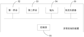
- the camera includes a main body 10 and a first screen 11, a second screen 12, a lens 13, and a shutter 14 disposed on the main body 10.
- the first screen 11 and the second screen 12 are separated from each other.
- the lens 13 is disposed on the second screen 12 side.
- the first screen 11 is a screen that displays an image captured by the lens 13 after the camera is started.
- the camera of this embodiment further includes a controller, and the controller is configured to obtain a first instruction.
- FIG. 3 is a second schematic diagram of the three-dimensional structure of the camera provided in the present application.
- the camera may further include a screen switching key 15.
- the controller obtains the first instruction, and controls to switch from the first screen 11 to the second screen 12 to display the image captured by the lens 13 or switch from the second screen 12 to the first screen 11 to display the image captured by the lens 13 based on the first instruction.
- FIG. 4 is a flowchart of a screen control method according to an embodiment of the present application. As shown in FIG. 4, the method in this embodiment may include:
- Step S101 Obtain a first instruction.
- the first instruction is used to control switching from the first screen 11 to the second screen 12 to display the image captured by the lens 13 or switching from the second screen 12 to the first screen 11 to display the image captured by the lens 13. ;
- Step S102 According to the first instruction, control to switch from the first screen 11 to the second screen 12 to display the image captured by the lens 13 or switch from the second screen 12 to the first screen 11 to display the image captured by the lens 13;
- the execution subject of this embodiment may be a camera shown in FIG. 1, FIG. 2, or FIG. 3;
- the image taken by the lens 13 is displayed on the first screen 11, when the user wants to take a selfie, the user performs a preset operation on the camera, and the controller of the camera obtains an instruction to switch the image taken by the display lens 13 according to the user's preset operation.
- the camera controls switching from the first screen 11 to the second screen 12 to display the image captured by the lens 13 according to the first instruction.
- the self-timer user can learn the image captured by the lens 13 through the second screen 12, and thus can capture the image the user wants.
- the second screen 12 faces the user at this time, and the controller controls the second screen 12 to display the image captured by the lens 13 so that the user can see the lens during the selfie Captured image.
- the user finishes taking a selfie and takes an image in a non-selfie scene, the user faces the lens 13 of the camera toward the object to be captured. At this time, the first screen 11 faces the user, and the user performs a preset operation on the camera again.
- the user's preset operation obtains a first instruction instructing to switch the screen of the image captured by the display lens 13;
- the camera controls switching from the second screen 12 to the first screen 11 to display the image captured by the lens 13.
- the non-self-timer user can learn the image captured by the lens 13 through the first screen 11 again, so that the user can capture the desired image.
- the user faces the lens 13 of the camera toward the object to be captured.
- the first screen 11 faces the user.
- the controller controls to display the image captured by the lens 13 on the first screen 11, the user You can see the image taken by the lens.
- the first screen 11 and the second screen 12 may be touch screens.
- the preset operation may be touching a preset track on the second screen 12 or the first screen 11 of the camera, sending a preset voice, and moving the camera according to a preset action. , Tap a preset position on the second screen 12 or the first screen 11, tap a screen switching key 15 provided on the body 10, and the like.
- the controller controls the first screen 11 to be in the off-screen state;
- the controller controls the second screen 12 to be in a screen-off state.
- the camera controls to switch from the first screen to the second screen to display the image captured by the lens or to switch from the second screen to the first screen to display the image captured by the lens according to the first instruction that instructs the display to switch the image captured by the lens.
- the second screen is the screen that the user is facing when taking a selfie. In this way, when the user takes a self-timer or a non-self-timer, the image captured by the lens can be seen, so that the user can capture the picture that the user wants to shoot, which improves the user experience.
- the screen control method may also have the following implementation manners: if the image captured by the lens 13 is displayed on the first screen 11 and the lens 13 is not displayed on the second screen 12
- the controller obtains the first instruction according to the preset operation
- the controller controls the image captured by the lens 13 on the second screen 12 according to the first instruction.
- the image taken by the lens 13 continues to be displayed on the screen 11. That is to say, the two screens simultaneously display images taken by the lens 13.
- a self-timer is converted into a non-self-timer, there is no need to perform a preset operation again, and when a self-timer is taken again, there is no need to perform a preset operation.
- FIG. 5 is a second flowchart of a screen control method according to an embodiment of the present application. As shown in FIG. 5, the method in this embodiment may include:
- Step S201 Obtain a touch track of a user on the second screen 12 or the first screen 11;
- Step S202 if the user's touch track on the second screen 12 or the first screen 11 is the same as the preset track stored by the camera, trigger a first instruction;
- Step S203 According to the first instruction, control is switched from the first screen 11 to the second screen 12 to display the image captured by the lens 13.
- the second screen 12 and / or the first screen 11 in this embodiment are touch screens.
- the controller obtains a touch track corresponding to the user's touch operation.
- the controller obtains a touch track corresponding to the user's touch operation.
- the camera control is switched from the first screen 11 to the second screen 12 to display the image captured by the lens 13.
- the camera lens 13 needs to face itself and the second screen 12 faces the user. After the controller controls to display the image captured by the lens 13 on the second screen 12, the user can see the image taken by the lens 13 when taking a selfie. image.
- the second screen 12 and the first screen 11 are both touch screens, when transitioning from a non-self-timer scene to a self-timer scene, after the image captured by the lens 13 can be displayed on the second screen 12, the user then changes the camera lens 13 is facing the user, and the user performs a touch operation on the first screen 11 at this time; if changing from a non-selfie scene to a selfie scene, the user first faces the camera lens 13 to the user, at this time, the second screen 12 faces the user, and the user is at the first Touch operation is performed on the two screens 12.
- the method of this embodiment enables a user to see an image captured by a lens when taking a self-portrait, so that a picture that the user wants to capture can be captured, and the user experience is improved.
- a method of screen control when changing from a self-timer to a non-self-timer, includes: obtaining a user's touch track on the first screen 11 or the second screen 12; if the user is on the first screen The first or second touch track on the 11 or the second screen 12 is the same as the preset track stored by the camera, and the first command is triggered; according to the first command, the control switches from the second screen 12 to the first screen 11 to display the image captured by the lens 13. The specific process is not repeated here.
- FIG. 6 is a third flowchart of a screen control method according to an embodiment of the present application. As shown in FIG. 6, the method in this embodiment may include:
- Step S301 Obtain a rotation angle of the camera.
- Step S302 if the rotation angle of the camera in the first preset time period is within the first preset range, trigger a first instruction
- Step S303 According to the first instruction, control is switched from the first screen 11 to the second screen 12 to display the image captured by the lens 13.
- the camera in this implementation includes an angle sensor.
- the angle sensor includes at least one of an electronic compass and a gyroscope.
- the user can rotate the camera at any angle within a first preset range within a first preset time period.
- the The angle sensor can detect the rotation angle or rotation angular velocity of the camera; if the angular velocity sensor is a gyroscope, the gyroscope can detect the rotation angular velocity of the camera, and the controller in the camera obtains the rotation angle of the camera according to the rotation angular velocity detected by the gyroscope. ; If the angular velocity sensor is an electronic compass, the electronic compass can detect the rotation angle of the camera, and the controller in the camera obtains the rotation angle of the camera detected by the electronic compass.
- the controller in the camera obtains that the rotation angle within the first preset time period is within the first preset range, if it is, it triggers a first instruction.
- the second screen 12 can be kept facing the user.
- the first preset duration is an arbitrary duration between 0.2 and 2 seconds.
- the first preset duration is an arbitrary duration between 0.5 and 1 s.
- the first preset range is 160 ° to 200 °, or -200 ° to -160 °;
- the first preset range is 170 ° to 180 °; or -190 ° to -170 °.
- a positive angle range indicates that the camera rotates clockwise
- a negative angle range indicates that the camera rotates counterclockwise
- the camera detects that the camera has rotated 180 ° within 1 s, it will trigger the first command; or if the camera detects that the camera has rotated -175 ° within 0.8 s, it will trigger the first command.
- the camera control is switched from the first screen 11 to the second screen 12 to display the image captured by the lens 13.
- the camera lens 13 needs to face itself and the second screen 12 faces the user. After the controller controls to display the image captured by the lens 13 on the second screen 12, the user can see the image taken by the lens 13 when taking a selfie. image.
- the method in this embodiment enables a user to see an image captured by a lens, so that a picture that the user wants to capture can be captured, and the user experience is improved.
- a method for controlling the screen includes: obtaining a rotation angle of the camera; if the rotation angle of the camera during a first preset period is in a first preset Within the range, a first instruction is triggered; according to the first instruction, control is switched from the second screen 12 to the first screen 11 to display the image captured by the lens 13. The specific process is not repeated here.
- FIG. 7 is a fourth flowchart of a screen control method according to an embodiment of the present application. As shown in FIG. 7, the method in this embodiment may include:
- Step S401 Acquire the acceleration of the camera in the X-axis direction, the acceleration in the Y-axis direction, and the acceleration in the Z-axis direction;
- Step S402 If the acceleration of the camera in the X-axis direction is within the second preset range within the second preset time period, the acceleration in the Y-axis direction is within the third preset range, and the acceleration in the Z-axis direction is within the fourth preset Within the range, the first instruction is triggered;
- Step S403 According to the first instruction, control is switched from the first screen 11 to the second screen 12 to display the image captured by the lens 13.
- the camera in this implementation may include an accelerometer or other structure that can measure the acceleration of the camera.
- the user can move the camera back and forth within a second preset time period, that is, the camera makes a round trip.
- the accelerometer in the camera detects the acceleration in the X-axis direction, the acceleration in the Y-axis direction, and the acceleration in the Z-axis direction during the camera movement.
- the controller in the camera acquires the X-axis during the camera movement.
- the second preset range, the third preset range, and the fourth preset range are ranges corresponding to the movement state of the camera when the camera moves back and forth.
- the back-and-forth motion can be any of back-and-forth motion, back-and-forth motion, up-and-down motion, or back-and-forth motion (that is, the user shakes or shakes the mobile phone at will) at a certain angle with the horizontal plane.
- the camera's back and forth movement can trigger the first instruction, it can move the camera back and forth within the second preset time period in advance to obtain the acceleration range of the camera in the X-axis direction, the acceleration range in the Y-axis direction, and the Z-axis direction. Acceleration range. This process is performed multiple times, and the second preset range, the third preset range, and the fourth preset range corresponding to the back and forth movement of the camera within the second preset time period are statistically obtained and stored in the camera when the camera leaves the factory. .
- the same method can be used to obtain the respective second preset range when the camera moves back and forth, up and down, or back and forth in a direction inclined to a horizontal plane within a second preset time period.
- each group of acceleration ranges includes a second preset range, a third preset range, and a fourth preset range.
- At least one of the at least four acceleration ranges can be stored in the camera at the factory.
- the camera stores the second preset range, the third preset range, and the fourth preset range corresponding to the left and right reciprocating movement of the camera within the second preset duration, it means that the first can be triggered when the camera reciprocates left and right.
- the user wants to display the image captured by the lens 13 on the second screen 12, the user can move the camera left and right within a second preset time period to make the camera reciprocate left and right.
- the second preset range, the third preset range, the fourth preset range, and the back and forth movements corresponding to the camera during the second preset duration are stored,
- the corresponding second preset range, third preset range, and fourth preset range indicate that the first instruction can be triggered when the camera moves back and forth or back and forth; if the user wants to display the lens on the second screen 12 During the captured image, the user can move the camera left or right or back and forth within a second preset time period to make the camera move back and forth or back and forth.
- the second preset duration is 0.5 to 2s.
- the user can move the camera in one direction within a second preset time period, that is, make the camera move in one direction.
- the accelerometer in the camera detects that the camera is in motion during the X, X The acceleration in the axis direction, the acceleration in the Y axis direction, and the acceleration in the Z axis direction.
- the controller in the camera obtains the acceleration in the X axis direction, the acceleration in the Y axis direction, and the acceleration in the Z axis direction.
- the acceleration in the Y-axis direction is within the third preset range
- the acceleration in the Z-axis direction is within the fourth preset range.
- the first command is triggered.
- the second preset range, the third preset range, and the fourth preset range are ranges corresponding to the movement state of the camera in the first direction.
- the movement in the first direction may be upward movement, downward movement, leftward movement, rightward movement, and tilting movement.
- each set of acceleration ranges includes: a second preset range, a third preset range, and a fourth preset range.
- At least one of at least five acceleration ranges can be stored in the camera at the factory.
- the second preset duration is 0.5 to 2s.
- the camera control is switched from the first screen 11 to the second screen 12 to display the image captured by the lens 13.
- the camera lens 13 needs to face itself and the second screen 12 faces the user. After the controller controls to display the image captured by the lens 13 on the second screen 12, the user can see the image taken by the lens 13 when taking a selfie. image.
- the method of this embodiment enables a user to see an image captured by a lens when taking a self-portrait, so that a picture that the user wants to capture can be captured, and the user experience is improved.
- the method of screen control includes: obtaining the acceleration of the camera in the X-axis direction, the acceleration in the Y-axis direction, and the acceleration in the Z-axis direction;
- the acceleration of the camera in the X-axis direction within the second preset time period is within the second preset range
- the acceleration in the Y-axis direction is within the third preset range
- the acceleration in the Z-axis direction is within the fourth preset range.
- a first instruction is triggered; according to the first instruction, control is switched from the second screen 12 to the first screen 11 to display an image captured by the lens 13. The specific process is not repeated here.
- FIG. 8 is a fifth flowchart of a screen control method according to an embodiment of the present application. As shown in FIG. 8, the method in this embodiment may include:
- Step S501 if a user's click operation for a preset number of times on a preset position of the second screen 12 or the first screen 11 is detected, a first instruction is triggered;
- Step S502 According to the first instruction, control is switched from the first screen 11 to the second screen 12 to display an image captured by the lens 13.
- the second screen 12 and / or the first screen 11 in this embodiment are touch screens.
- a preset icon button may be displayed on the second screen 12 and / or the first screen 11 of the camera in this embodiment.
- the user can click the preset icon button on the second screen 12 or the first screen 11, and the camera detects A single click operation of a preset icon button on the second screen 12 or the first screen 11 by a user triggers a first instruction.
- the preset position is the position where the preset icon button on the second screen 12 or the first screen 11 is located.
- the name of the preset icon button may be a switching screen or a control screen.
- the user may click the blank area on the second screen 12 or the first screen 11 a preset number of times, and the camera may detect the preset number of times of the blank area on the second screen 12 or the first screen 11 by the user. Click on the operation to trigger the first instruction.
- the preset position is a blank area on the second screen 12 or the first screen 11.
- the preset number of times is 1, or 2 or 3 times.
- the camera control is switched from the first screen 11 to the second screen 12 to display the image captured by the lens 13.
- the camera lens 13 needs to face itself and the second screen 12 faces the user. After the controller controls to display the image captured by the lens 13 on the second screen 12, the user can see the image taken by the lens 13 when taking a selfie. image.
- the second screen 12 and the first screen 11 are both touch screens, when transitioning from a non-self-timer scene to a self-timer scene, after the image captured by the lens 13 can be displayed on the second screen 12, the user then changes the camera lens 13 is facing the user, and the user clicks on the first screen 11 at this time; if changing from a non-selfie scene to a selfie scene, the user first faces the camera lens 13 to the user, at this time, the second screen 12 faces the user, and the user is at the first Click on the second screen 12.
- the method of this embodiment enables a user to see an image captured by a lens when taking a self-portrait, so that a picture that the user wants to capture can be captured, and the user experience is improved.
- a method of screen control when switching from a self-timer to a non-self-timer, includes: if a preset number of times a user presets a preset position of the first screen 11 or the second screen 12 is detected; A click operation triggers a first instruction. According to the first instruction, control is switched from the second screen 12 to the first screen 11 to display an image captured by the lens 13. The specific process is not repeated here.
- FIG. 9 is a fifth flowchart of a screen control method according to an embodiment of the present application. As shown in FIG. 9, the method in this embodiment may include:
- Step S601 If a user's operation on a preset physical button of the camera is detected, a first instruction is triggered;
- Step S602 According to the first instruction, control is switched from the first screen 11 to the second screen 12 to display an image captured by the lens 13.
- the camera in this embodiment is a camera having preset physical keys.
- the user can operate the preset physical button, and the camera detects the user's operation on the preset physical button, and triggers the first instruction.
- the preset physical button may be a screen physical button newly added to the camera, which is specifically used to switch the image captured by the display lens 13, such as the screen switching button 15 shown in FIG. 3.
- the physical keys are not limited to pushable keys, but may also be slidable keys.
- the user's operation of the preset physical button can be the user clicking the preset physical button (that is, immediately released after pressing the preset physical button), the user can slide the preset physical button from the first position to the second position, and can also The user presses a preset physical button for a third preset duration.
- the third preset duration is an arbitrary duration between 1s and 2s.
- the camera switches from the first screen 11 to the second screen 12 to display the image captured by the lens 13.
- the camera lens 13 needs to face itself and the second screen 12 faces the user. After the controller controls to display the image captured by the lens 13 on the second screen 12, the user can see the image taken by the lens 13 when taking a selfie. image.
- the method of this embodiment enables a user to see an image captured by a lens when taking a self-portrait, so that a picture that the user wants to capture can be captured, and the user experience is improved.
- a method of screen control when switching from a self-timer to a non-self-timer, includes: if a user's operation of a preset physical button of the camera is detected, a first instruction is triggered; An instruction to control switching from the second screen 12 to the first screen 11 to display an image captured by the lens 13. The specific process is not repeated here.
- FIG. 10 is a sixth flowchart of a screen control method according to an embodiment of the present application. As shown in FIG. 10, the method in this embodiment may include:
- Step S701 Acquire a user's voice signal
- Step S702 Recognize a user's voice signal and obtain text information corresponding to the user's voice signal.
- Step S703 If the text information is the same as the text information pre-stored by the camera, trigger a first instruction.
- Step S704 According to the first instruction, control is switched from the first screen 11 to the second screen 12 to display the image captured by the lens 13.
- the camera in this embodiment is a camera having a voice receiver and a voice recognition function.
- the voice receiver in this implementation may be a microphone.
- the user can speak a preset word or sentence, and the camera's voice receiver receives the voice signal corresponding to the preset word or sentence; the camera The controller can obtain the voice signal, recognize the voice signal, and obtain the text information corresponding to the voice signal; and determine whether the text message corresponding to the voice signal is the same as the text information pre-stored by the camera, and if so, trigger the first instruction .
- the preset word can be "switch” or "screen", and the preset sentence can be "display image on the front screen”.
- the text information pre-stored by the camera is "switch".
- the camera control is switched from the first screen 11 to the second screen 12 to display the image captured by the lens 13.
- the camera lens 13 needs to face itself and the second screen 12 faces the user. After the controller controls to display the image captured by the lens 13 on the second screen 12, the user can see the image taken by the lens 13 when taking a selfie. image.
- the method of this embodiment enables a user to see an image captured by a lens when taking a self-portrait, so that a picture that the user wants to capture can be captured, and the user experience is improved.
- a method of screen control includes: acquiring a user's voice signal; identifying the user's voice signal, and obtaining text information corresponding to the user's voice signal; If the text information is the same as the text information pre-stored by the camera, a first instruction is triggered; according to the first instruction, control is switched from the second screen 12 to the first screen 11 to display the image captured by the lens 13. The specific process is not repeated here.
- FIG. 11 is a seventh flowchart of a screen control method according to an embodiment of the present application. As shown in FIG. 11, the method in this embodiment may include:
- Step S801 Acquire an image displayed on the first screen 11.
- Step S802 if the face image included in the image displayed on the first screen 11 is the target face image, and the ratio of the target face image to the image displayed on the first screen 11 is greater than a preset ratio, triggering a first instruction ;
- the target face image is a face image stored in the camera;
- Step S803 According to the first instruction, control is switched from the first screen 11 to the second screen 12 to display the image captured by the lens 13.
- the camera of this embodiment may include an image collector that is communicatively connected with the controller.
- the image taken by the lens 13 is displayed on the first screen 11, when the user wants to take a selfie, the user can place his face as close to the lens 13 as possible, and the image collector collects the entire image displayed on the first screen 11, the camera The controller acquires the collected entire image displayed on the first screen 11 and detects whether the face image in the entire image is the target face image, and if so, determines whether the ratio of the target face image to the entire image is greater than a preset ratio, If yes, the first instruction is triggered.
- the target face image is a face image stored in the camera.
- the preset ratio is any ratio between 90% and 100%;
- the preset ratio is any ratio between 95% and 100%
- the preset ratio is stored in the camera.
- the camera control is switched from the first screen 11 to the second screen 12 to display the image captured by the lens 13.
- the camera lens 13 needs to face itself and the second screen 12 faces the user. After the controller controls to display the image captured by the lens 13 on the second screen 12, the user can see the image taken by the lens 13 when taking a selfie. image.
- the method of this embodiment enables a user to see an image captured by a lens when taking a self-portrait, so that a picture that the user wants to capture can be captured, and the user experience is improved.
- the method of screen control includes: acquiring an image displayed on the second screen 12; if the image included on the image displayed on the second screen 12 includes The face image is the target face image, and the ratio of the target face image to the image displayed on the second screen 12 is greater than the preset ratio, then the first command is triggered; the target face image is the face image stored in the camera; A first instruction controls switching from the second screen 12 to the first screen 11 to display an image captured by the lens 13. The specific process is not repeated here.
- FIG. 12 is a first schematic structural diagram of a screen control apparatus according to an embodiment of the present invention.
- the screen control apparatus 400 in this embodiment may include a memory 41 and a processor 42, and the memory 41 is coupled to the processor 42.
- a memory 41 for storing program instructions
- the processor 42 is configured to call a program instruction in the memory 41 to execute the solutions of the foregoing embodiments.
- the screen control device in this embodiment may be used to execute the technical solutions in the foregoing method embodiments.
- the implementation principles and technical effects are similar, and details are not described herein again.
- the controller in the following embodiments is at least part of the processor 41.
- FIG. 13 is a second schematic diagram of the structure of a screen control device according to an embodiment of the present invention.
- the screen control device of this embodiment includes a body, and a first screen and a second screen provided on the body And the lens, and a controller provided in the body; the first screen and the second screen are disposed away from each other, and the lens is provided on the second screen side; the controller is in Two screens and a lens are connected for communication; the first screen is a screen that displays the image captured by the lens after the screen-controlled device is started;
- the controller 51 is configured to obtain a first instruction; the first instruction is used to instruct displaying an image captured by the lens on the second screen; and
- Controlling according to the first instruction, displaying on the second screen an image captured by the lens.
- the screen control device in this embodiment may be used to execute the technical solutions in the foregoing method embodiments.
- the implementation principles and technical effects are similar, and details are not described herein again.
- the controller is specifically configured to:
- the image captured by the lens displayed on the first screen is switched to be displayed on the second screen.
- the controller is further specifically configured to control the screen-off state of the first screen.
- the controller is specifically configured to obtain a user's touch track on the second screen or the first screen, and if the touch track is the same as a preset track stored by the camera, a first instruction is triggered.
- the controller is specifically configured to trigger a first instruction if a user's click operation is detected a preset number of times at the preset position on the second screen or the first screen.
- the preset position is a position where the preset icon button on the second screen or the first screen is located; or,
- the preset position is a blank area on the second screen or the first screen.
- the preset number of times is 1 or 2 or 3 times.
- the screen control device in this embodiment may be used to execute the technical solutions in the foregoing method embodiments.
- the implementation principles and technical effects are similar, and details are not described herein again.
- FIG. 14 is a third structural schematic diagram of a screen control device according to an embodiment of the present invention. As shown in FIG. 14, the screen control device of this embodiment is based on the screen control device shown in FIG. 13, and further includes: The angle sensor 55 communicably connected to the controller 51;
- the angle sensor 55 is configured to detect a rotation angle or a rotation angular velocity of the camera
- the controller 51 is specifically configured to obtain a rotation angle of a camera according to a rotation angle or a rotation angular velocity detected by the angle sensor, and if the rotation angle of the camera within a first preset duration range is within the first preset range When within, trigger the first instruction.
- the first preset duration is an arbitrary duration between 0.2 and 2 seconds.
- the first preset duration is an arbitrary duration between 0.5 and 1 s.
- the first preset range is 160 ° to 200 °, or -200 ° to -160 °;
- the first preset range is 170 ° to 180 °; or -190 ° to -170 °.
- the screen control device in this embodiment may be used to execute the technical solutions in the foregoing method embodiments.
- the implementation principles and technical effects are similar, and details are not described herein again.
- FIG. 15 is a fourth structural diagram of a device for screen control according to an embodiment of the present invention. As shown in FIG. 15, the device for screen control in this embodiment is based on the device for screen control shown in FIG. 13, and further includes: The accelerometer 56 in communication connection with the controller 51;
- the accelerometer 56 is used to detect the acceleration of the camera in the X-axis direction, the acceleration in the Y-axis direction, and the acceleration in the Z-axis direction;
- the controller 51 is specifically configured to:
- the first instruction is triggered.
- the second preset duration is an arbitrary duration between 0.5s and 2s.
- the second preset range, the third preset range, and the fourth preset range are ranges corresponding to when the motion state of the camera is a round trip.
- the second preset range, the third preset range, and the fourth preset range are ranges corresponding to a movement state of the camera in a first direction.
- the screen control device in this embodiment may be used to execute the technical solutions in the foregoing method embodiments.
- the implementation principles and technical effects are similar, and details are not described herein again.
- FIG. 16 is a fifth schematic structural diagram of a screen control device according to an embodiment of the present invention. As shown in FIG. 16, the screen control device of this embodiment is based on the screen control device shown in FIG. 13, and further includes: A preset physical button 57 communicably connected by the controller 51;
- the controller 51 is specifically configured to trigger a first instruction if a user operation on the preset physical key is detected.
- the user's operation of the preset physical keys of the camera includes any one of the following:
- the user slides the preset physical key from a first position to a second position;
- the third preset duration is an arbitrary duration between 1s and 2s.
- the screen control device in this embodiment may be used to execute the technical solutions in the foregoing method embodiments.
- the implementation principles and technical effects are similar, and details are not described herein again.
- FIG. 17 is a sixth schematic diagram of the structure of a screen control device according to an embodiment of the present invention. As shown in FIG. 17, the screen control device of this embodiment is based on the screen control device shown in FIG. 13, and further includes: A voice receiver 58 communicably connected to the controller 51;
- the voice receiver 58 is configured to receive a voice signal of a user
- the controller 51 is specifically configured to:
- the screen control device in this embodiment may be used to execute the technical solutions in the foregoing method embodiments.
- the implementation principles and technical effects are similar, and details are not described herein again.
- FIG. 18 is a schematic structural diagram of a screen control device according to an embodiment of the present invention. As shown in FIG. 18, the screen control device of this embodiment is based on the screen control device shown in FIG. 13, and further includes: Controller 51 image collector 59 communicatively connected
- the image collector 59 is configured to collect an image displayed on the first screen
- the controller 51 is specifically configured to acquire the image, and if a face image included in the image is a target face image, and the ratio of the target face image to the image is greater than a preset ratio, triggering First instruction; the target face image is a face image stored in the device controlled by the screen.
- the preset ratio is any ratio between 90% and 100%.
- the screen control device in this embodiment may be used to execute the technical solutions in the foregoing method embodiments.
- the implementation principles and technical effects are similar, and details are not described herein again.
- a person of ordinary skill in the art may understand that all or part of the steps of implementing the foregoing method embodiments may be implemented by a program instructing related hardware.
- the aforementioned program may be stored in a computer-readable storage medium.
- the steps including the foregoing method embodiments are performed; and the foregoing storage medium includes various media that can store program codes, such as a ROM, a RAM, a magnetic disk, or an optical disc.
Abstract
一种屏幕控制的方法和装置,该方法应用于终端设备,终端设备包括机身(10)、以及设置在所述机身(10)上的第一屏幕(11),第二屏幕(12)和镜头(13),第一屏幕(11)和第二屏幕(12)相背离设置,所述镜头(13)设置在所述第二屏幕(12)侧,所述第一屏幕(11)为所述终端设备在启动后显示所述镜头(13)拍摄的图像的屏幕;该方法包括:获取第一指令;第一指令用于指示在第二屏幕(12)上显示镜头(13)拍摄的图像;根据第一指令,控制第二屏幕(12)上显示镜头(13)拍摄的图像。该方法和装置使得用户在自拍时,可获知镜头(13)拍摄的图像,从而用户能够拍摄到想要的画面,提升了用户的使用体验。
Description
本申请涉及智能终端技术,尤其涉及一种屏幕控制的方法和装置。
目前,为了方便用户自拍时获知自拍的拍摄参数,相机会设置两个屏幕;自拍时,第一屏幕显示镜头拍摄的图像,第二屏幕显示拍摄参数。
但是,由于相机的镜头只有一个,且由于镜头拍摄方向的限制,镜头拍摄的图像显示在第一屏幕上,而在自拍时,第一屏幕背对用户,用户无法获知镜头拍摄的图像都有哪些,不易拍到自己想要的画面。
发明内容
本申请实施例提供一种屏幕控制的方法和装置,以使用户自拍时可以获知镜头拍摄的图像,从而拍摄到自己想要的画面。
第一方面,本申请实施例提供一种屏幕控制的方法,应用于终端设备,所述终端设备包括机身、以及设置在所述机身上的第一屏幕,第二屏幕和镜头,第一屏幕和第二屏幕相背离设置,所述镜头设置在所述第二屏幕侧,所述第一屏幕为所述终端设备在启动后显示所述镜头拍摄的图像的屏幕;所述方法包括:
获取第一指令,所述第一指令用于指示在所述第二屏幕上显示所述镜头拍摄的图像;
根据所述第一指令,控制所述第二屏幕上显示所述镜头拍摄的图像。
在一种可能的设计中,所述根据所述第一指令,控制所述第二屏幕上显示所述镜头拍摄的图像,包括:
根据所述第一指令,将在第一屏幕上显示的所述镜头拍摄的图像切换至所述第二屏幕上显示。
在一种可能的设计中,在将在第一屏幕上显示的所述镜头拍摄的图像切换至所述第二屏幕上显示之后,还包括:
控制所述第一屏幕处于灭屏状态。
在一种可能的设计中,所述获取第一指令,包括:
获取用户在所述第二屏幕或所述第一屏幕上的触摸轨迹;
若所述触摸轨迹与所述终端设备存储的预设轨迹相同,则触发第一指令。
在一种可能的设计中,所述获取第一指令,包括:
获取终端设备的旋转角度;
若终端设备在第一预设时长内的旋转角度在第一预设范围内,则触发第一指令。
在一种可能的设计中,所述获取终端设备的旋转角度,包括:
获取通过所述终端设备的角度传感器检测的终端设备的旋转角度;所述角度传感器包括电子罗盘、陀螺仪中的至少一项。
在一种可能的设计中,所述第一预设时长为0.2~2s之间的任意时长。
在一种可能的设计中,所述第一预设时长为0.5~1s之间的任意时长。
在一种可能的设计中,所述第一预设范围为160°~200°,或者-200°~-160°;
在一种可能的设计中,所述第一预设范围为170°~180°;或者-190°~-170°。
在一种可能的设计中,所述获取第一指令,包括:
获取终端设备在X轴方向的加速度、Y轴方向的加速度和Z轴方向的加速度;
若到终端设备在第二预设时长内X轴方向的加速度在第二预设范围内,在Y轴方向的加速度在第三预设范围内,在Z轴方向的加速度在第四预设范围内,则触发第一指令。
在一种可能的设计中,所述第二预设时长为0.5s~2s之间的任意时长。
在一种可能的设计中,所述第二预设范围和所述第三预设范围和所述第四预设范围均为所述终端设备的运动状态为往返运动时对应的范围。
在一种可能的设计中,所述第二预设范围和所述第三预设范围和所述第四预设范围均为所述终端设备的运动状态为向第一方向运动时对应的范围。
在一种可能的设计中,所述获取第一指令,包括:
若检测到用户对所述第二屏幕或所述第一屏幕的预设位置的预设次数的点击操作,则触发第一指令。
在一种可能的设计中,所述预设位置为所述第二屏幕或所述第一屏幕上的预设图标按钮所在的位置;或者,
所述预设位置为所述第二屏幕或所述第一屏幕上的空白区域。
在一种可能的设计中,所述预设次数为1次或2次或3次。
在一种可能的设计中,所述获取第一指令,包括:
若检测到用户对所述终端设备的预设物理按键的操作,则触发第一指令。
在一种可能的设计中,所述用户对所述终端设备的预设物理按键的操作包括如下中的任一项:
用户点击预设物理按键;
用户将预设物理按键从第一位置滑动至第二位置;
用户按动第三预设时长的预设物理按键。
在一种可能的设计中,所述第三预设时长为1s~2s之间的任意时长。
在一种可能的设计中,所述获取第一指令,包括:
获取用户的语音信号;
识别所述语音信号,得到所述语音信号对应的文本信息;
若所述文本信息与所述终端设备预存的文本信息相同,则触发第一指令。
在一种可能的设计中,所述获取第一指令,包括:
获取所述第一屏幕上显示的图像;
若所述图像中包括的人脸图像为目标人脸图像,且所述目标人脸图像占所述图像的比例大于预设比例,则触发第一指令;所述目标人脸图像为所述终端设备内存储的人脸图像。
在一种可能的设计中,所述预设比例为90%~100%之间的任意比例。
第二方面,本申请实施提供一种相机,包括:机身,设置在所述机身上的第一屏幕、第二屏幕和镜头,以及设置在所述机身内的控制器;所述第一屏幕和第二屏幕相背离设置,所述镜头设置在所述第二屏幕侧;所述 控制器与第一屏幕、第二屏幕和镜头通信连接;所述第一屏幕为所述屏幕控制的装置在启动后显示所述镜头拍摄的图像的屏幕;
所述控制器,用于获取第一指令;所述第一指令用于指示在所述第二屏幕上显示所述镜头拍摄的图像;以及,
根据所述第一指令,控制所述第二屏幕上显示所述镜头拍摄的图像。
在一种可能的设计中,所述控制器具体用于:
根据所述第一指令,将在第一屏幕上显示的所述镜头拍摄的图像切换至所述第二屏幕上显示。
在一种可能的设计中,所述控制器还具体用于:控制所述第一屏幕处于灭屏状态。
在一种可能的设计中,
所述控制器,具体用于获取用户在所述第二屏幕或所述第一屏幕的触摸轨迹,若所述触摸轨迹与所述相机存储的预设轨迹相同,则触发第一指令。
在一种可能的设计中,所述控制器,具体用于:
获取相机的旋转角度;
若相机在第一预设时长内的旋转角度在第一预设范围内,则触发第一指令。
在一种可能的设计中,所述相机还包括与所述控制器通信连接的角度传感器;
所述角度传感器,用于检测相机的旋转角度或者旋转角速度;
所述控制器,具体用于:根据所述角度传感器检测的旋转角度或者旋转角速度,获取相机的旋转角度,若所述相机在第一预设时长范围内的旋转角度在第一预设范围内时,触发第一指令。
在一种可能的设计中,所述第一预设时长为0.2~2s之间的任意时长。
在一种可能的设计中,所述第一预设时长为0.5~1s之间的任意时长。
在一种可能的设计中,所述第一预设范围为160°~200°,或者-200°~-160°;
在一种可能的设计中,所述第一预设范围为170°~180°;或者-190°~-170°。
在一种可能的设计中,所述相机还包括与所述控制器通信连接的加速度计;
所述加速度计用于检测相机在X轴方向的加速度、Y轴方向的加速度和Z轴方向的加速度;
所述控制器具体用于:
获取所述加速度计检测得到的相机在X轴方向的加速度、Y轴方向的加速度和Z轴方向的加速度;
若相机在第二预设时长内X轴方向的加速度在第二预设范围内,在Y轴方向的加速度在第三预设范围内,在Z轴方向的加速度在第四预设范围内,则触发第一指令。
在一种可能的设计中,所述第二预设时长为0.5s~2s之间的任意时长。
在一种可能的设计中,所述第二预设范围和所述第三预设范围和所述第四预设范围均为所述相机的运动状态为往返运动时对应的范围。
在一种可能的设计中,所述第二预设范围和所述第三预设范围和所述第四预设范围均为所述相机的运动状态为向第一方向运动时对应的范围。
在一种可能的设计中,
所述控制器,具体用于若检测到用户在所述第二屏幕或所述第一屏幕上的预设位置处预设次数的点击操作,触发第一指令。
在一种可能的设计中,所述预设位置为所述第二屏幕或所述第一屏幕上的预设图标按钮所在的位置;或者,
所述预设位置为所述第二屏幕或所述第一屏幕上的空白区域。
在一种可能的设计中,所述预设次数为1次或2次或3次。
在一种可能的设计中,所述相机还包括设置在所述相机侧壁上的预设物理按键;所述预设物理按键与所述控制器通信连接;
所述控制器,具体用于若检测到用户对所述预设物理按键的操作,则触发第一指令。
在一种可能的设计中,所述用户对所述相机的预设物理按键的操作包括如下中的任一项:
用户点击所述预设物理按键;
用户将所述预设物理按键从第一位置滑动至第二位置;
用户按动第三预设时长的所述预设物理按键。
在一种可能的设计中,所述第三预设时长为1s~2s之间的任意时长。
在一种可能的设计中,所述相机还包括与所述控制器通信连接的语音接收器;
所述语音接收器用于接收用户的语音信号;
所述控制器具体用于:
从所述语音接收器获取用户的语音信号;
识别所述语音信号,得到所述语音信号对应的文本信息;
若所述文本信息与所述相机预存的文本信息相同,则触发第一指令。
在一种可能的设计中,所述屏幕控制的装置还包括与所述控制器通信连接的图像采集器;
所述图像采集器,用于采集所述第一屏幕上显示的图像;
所述控制器,具体用于获取所述图像,若所述图像中包括的人脸图像为目标人脸图像,且所述目标人脸图像占所述图像的比例大于预设比例,则触发第一指令;所述目标人脸图像为所述屏幕控制的装置内存储的人脸图像。
在一种可能的设计中,所述预设比例为90%~100%之间的任意比例。
第三方面,本发明实施例提供一种屏幕控制的装置,包括:存储器和处理器,存储器与处理器耦合;
存储器,用于存储程序指令;
处理器,用于调用存储器中的程序指令执行上述第一方面以及各可能的设计中所述的方法。
第四方面,本发明实施例提供一种计算机可读存储介质,该计算机可读存储介质存储有计算机程序,该计算机程序包含至少一段代码,该至少一段代码可由计算机执行,以控制所述计算机执行上述第一方面以及各可能的设计中所述的方法。
第五方面,本发明实施例提供一种计算机程序,当所述计算机程序被计算机执行时,用于执行上述第一方面以及各可能的设计中所述的方法。
所述程序可以全部或者部分存储在与处理器封装在一起的存储介质上,也可以部分或者全部存储在不与处理器封装在一起的存储介质上。存 储介质例如为存储器。
综上所述,本申请的屏幕控制装置根据指示在相机的第二屏幕上显示镜头拍摄的图像的指令,控制镜头拍摄的图像在第二屏幕上显示,第二屏幕为自拍时用户面向的屏幕。这样,在用户自拍时,就可以看到镜头拍摄的图像,从而可以拍摄到用户想要拍摄的画面,提升了用户的使用体验。
为了更清楚地说明本申请实施例或现有技术中的技术方案,下面将对实施例或现有技术描述中所需要使用的附图作一简单地介绍,显而易见地,下面描述中的附图是本申请的一些实施例,对于本领域普通技术人员来讲,在不付出创造性劳动性的前提下,还可以根据这些附图获得其他的附图。
图1为本申请提供的相机的立体结构示意图一;
图2为图1中的相机沿A方向的主视图;
图3为本申请提供的相机的立体结构示意图二;
图4为本申请实施例提供的屏幕控制的方法的流程图一;
图5为本申请实施例提供的屏幕控制的方法的流程图二;
图6为本申请实施例提供的屏幕控制的方法的流程图三;
图7为本申请实施例提供的屏幕控制的方法的流程图四;
图8为本申请实施例提供的屏幕控制的方法的流程图五;
图9为本申请实施例提供的屏幕控制的方法的流程图六;
图10为本申请实施例提供的屏幕控制的方法的流程图七;
图11为本申请实施例提供的屏幕控制的方法的流程图八;
图12为本发明实施例提供的屏幕控制的装置结构示意图一;
图13为本发明实施例提供的屏幕控制的装置结构示意图二;
图14为本发明实施例提供的屏幕控制的装置结构示意图三;
图15为本发明实施例提供的屏幕控制的装置结构示意图四;
图16为本发明实施例提供的屏幕控制的装置结构示意图五;
图17为本发明实施例提供的屏幕控制的装置结构示意图六;
图18为本发明实施例提供的屏幕控制的装置结构示意图七。
为使本申请实施例的目的、技术方案和优点更加清楚,下面将结合本申请实施例中的附图,对本申请实施例中的技术方案进行清楚、完整地描述,显然,所描述的实施例是本申请一部分实施例,而不是全部的实施例。基于本申请中的实施例,本领域普通技术人员在没有作出创造性劳动前提下所获得的所有其他实施例,都属于本申请保护的范围。
本申请实施例提供了屏幕控制的方法和装置。屏幕控制的装置可为相机。当用户使用相机非自拍时,用户面向第一屏幕,用户可清楚的获知镜头拍摄的图像,从而拍摄自己想要的画面;当用户自拍时,用户面向第二屏幕,第一屏幕上显示的镜头拍摄的图像,用户无法获知。
为了解决上述问题,本申请实施例提供了一种相机;图1为本申请提供的相机的立体结构示意图一,图2为图1中的相机沿A方向的主视图;参见图1和图2,相机包括机身10、以及设置在机身10上的第一屏幕11,第二屏幕12、镜头13、和快门14。第一屏幕11和第二屏幕12相背离设置,镜头13设置在第二屏幕12侧,第一屏幕11为相机在启动后显示镜头13拍摄的图像的屏幕。本实施例的相机还包括控制器,控制器用于获取第一指令。
可以理解的是,由于第一屏幕11和第二屏幕12相背离设置,因此,图1中只可以看到第二屏幕12,图2中可清楚的看到第一屏幕11。
图3为本申请提供的相机的立体结构示意图二,参见图3,在图1和图2提供的相机的基础上,相机还可包括屏幕切换键15,当用户操作屏幕切换键15时,控制器获取到第一指令,并基于第一指令控制从第一屏幕11切换至第二屏幕12显示镜头13拍摄的图像或者从第二屏幕12切换至第一屏幕11显示镜头13拍摄的图像。
下面结合具体的实施例对本申请实施例提供的图1、图2或图3中所示的相机的屏幕控制的方法进行说明。
图4为本申请实施例提供的屏幕控制的方法的流程图,如图4所示,本实施例的方法可以包括:
步骤S101、获取第一指令,第一指令用于控制从第一屏幕11切换至 第二屏幕12显示镜头13拍摄的图像,或者从第二屏幕12切换至第一屏幕11显示镜头13拍摄的图像;
步骤S102、根据第一指令,控制从第一屏幕11切换至第二屏幕12显示镜头13拍摄的图像或者从第二屏幕12切换至第一屏幕11显示镜头13拍摄的图像;
具体地,本实施例的执行主体可为图1、图2或图3中所示的相机;
若第一屏幕11上显示有镜头13拍摄的图像,当用户想要自拍时,则用户对相机进行预设操作,相机的控制器根据用户的预设操作获取到指示切换显示镜头13拍摄的图像的屏幕的第一指令;
接着,相机根据第一指令,控制从第一屏幕11切换至第二屏幕12显示镜头13拍摄的图像。这样,自拍的用户便可通过第二屏幕12获知镜头13拍摄的图像,从而可拍摄到用户想要的画面。
由于自拍过程中,需要将相机的镜头13面向自己,此时,第二屏幕12面对用户,控制器控制在第二屏幕12显示镜头13拍摄的图像后,用户在自拍时便可以看到镜头拍摄的图像。
在用户自拍完毕,在非自拍场景下拍摄图像时,用户将相机的镜头13面向待拍摄的物体,此时,第一屏幕11面向用户,用户再次对相机进行预设操作,相机的控制器根据用户的预设操作获取到指示切换显示镜头13拍摄的图像的屏幕的第一指令;
接着,相机根据第一指令,控制从第二屏幕12切换至第一屏幕11显示镜头13拍摄的图像。这样,非自拍的用户便可重新通过第一屏幕11获知镜头13拍摄的图像,从而可拍摄到用户想要的画面。
而在非自拍过程中,用户将相机的镜头13面向待拍摄的物体,此时,第一屏幕11面向用户,控制器控制在第一屏幕11显示镜头13拍摄的图像后,用户在非自拍时便可以看到镜头拍摄的图像。
其中,第一屏幕11和第二屏幕12可为触摸屏,预设操作可为在相机的第二屏幕12或第一屏幕11上触摸预设的轨迹、发出预设语音、按照预设动作移动相机、点击第二屏幕12或第一屏幕11上的预设位置、点击设置在机身10上的屏幕切换键15等。
进一步地,为了节省相机的能耗,在控制从第一屏幕11切换至第二 屏幕12显示镜头13拍摄的图像之后,控制器控制第一屏幕11处于灭屏状态;或者,
在控制从第二屏幕12切换至第一屏幕11显示镜头13拍摄的图像之后,控制器控制第二屏幕12处于灭屏状态。
本实施例中,相机根据指示切换显示镜头拍摄的图像的第一指令,控制从第一屏幕切换至第二屏幕显示镜头拍摄的图像或者从第二屏幕切换至第一屏幕显示镜头拍摄的图像,第二屏幕为自拍时用户面向的屏幕。这样在用户自拍和非自拍时,均可以看到镜头拍摄的图像,从而可以拍摄到用户想要拍摄的画面,提升了用户的使用体验。
此外,除了图1所示的实施例中的屏幕控制方法,屏幕控制方法还可具有如下的实施方式:若第一屏幕11上显示有镜头13拍摄的图像,第二屏幕12未显示有镜头13拍摄的图像,当用户自拍时,用户对相机进行预设操作,控制器根据预设操作获取到第一指令后,根据第一指令控制第二屏幕12上显示镜头13拍摄的图像,但是第一屏幕11上仍然继续显示镜头13拍摄的图像。也就是说两个屏幕同时显示镜头13拍摄的图像。该种实施方式下,当从自拍转化成非自拍时,无需再次进行预设操作,再次自拍时,也无需进行预设操作。
下面采用图5~图11所示的实施例,对图1所示的实施例中的用户自拍场景下的屏幕控制的方法进行详细说明。
图5为本申请实施例提供的屏幕控制的方法的流程图二,如图5所示,本实施例的方法可以包括:
步骤S201、获取用户在第二屏幕12或第一屏幕11上的触摸轨迹;
步骤S202、若用户在第二屏幕12或第一屏幕11上的触摸轨迹与相机存储的预设轨迹相同,则触发第一指令;
步骤S203、根据第一指令,控制从第一屏幕11切换至第二屏幕12显示镜头13拍摄的图像。
具体地,本实施中的第二屏幕12和/或第一屏幕11为触摸屏。
若第一屏幕11上显示有镜头13拍摄的图像,当用户想要自拍时,用户的手指在第一屏幕11上或者第二屏幕12上进行触摸操作,控制器获取用户触摸操作对应的触摸轨迹,判断用户在第一屏幕11上或者第二屏 幕12上的触摸轨迹与相机内存储的预设轨迹是否相同,若相同,则触发第一指令;
接着,第一指令被触发后,相机控制从第一屏幕11切换至第二屏幕12显示镜头13拍摄的图像。
由于自拍过程中,需要将相机的镜头13面向自己,第二屏幕12面对用户,控制器控制在第二屏幕12显示镜头13拍摄的图像后,用户在自拍时便可以看到镜头13拍摄的图像。
可以理解的是,若第二屏幕12和第一屏幕11均为触摸屏,在从非自拍场景转至自拍场景时,可在第二屏幕12显示镜头13拍摄的图像后,用户再将相机的镜头13面向用户,此时用户在第一屏幕11上进行触摸操作;若从非自拍场景转至自拍场景,用户先将相机的镜头13面向用户,此时,第二屏幕12面向用户,用户在第二屏幕12上进行触摸操作。
本实施例的方法使得用户在自拍时可以看到镜头拍摄的图像,从而可以拍摄到用户想要拍摄的画面,提升了用户的使用体验。
与图5所示的实施例相对应的,若从自拍转成非自拍时,屏幕控制的方法包括:获取用户在第一屏幕11或第二屏幕12上的触摸轨迹;若用户在第一屏幕11或第二屏幕12上的触摸轨迹与相机存储的预设轨迹相同,则触发第一指令;根据第一指令,控制从第二屏幕12切换至第一屏幕11显示镜头13拍摄的图像。具体过程此处不再赘述。
图6为本申请实施例提供的屏幕控制的方法的流程图三,如图6所示,本实施例的方法可以包括:
步骤S301、获取相机的旋转角度;
步骤S302、若相机在第一预设时长的旋转角度在第一预设范围内,则触发第一指令;
步骤S303、根据第一指令,控制从第一屏幕11切换至第二屏幕12显示镜头13拍摄的图像。
具体地,本实施中的相机包括角度传感器。角度传感器包括电子罗盘、陀螺仪中的至少一项。
若第一屏幕11上显示有镜头13拍摄的图像,当用户想要自拍时,用户可在第一预设时长内将相机旋转第一预设范围内的任一角度,此时,相 机内的角度传感器可检测到相机的旋转角度或旋转角速度;若角速度传感器为陀螺仪,则陀螺仪可检测相机的旋转角速度,相机内的控制器根据陀螺仪检测到的旋转角速度,获取到相机的旋转角度;若角速度传感器为电子罗盘,则电子罗盘可检测相机的旋转角度,相机内的控制器获取电子罗盘检测到的相机的旋转角度。
相机内的控制器若获取到第一预设时长内的旋转角度在第一预设范围内,若在,则触发第一指令。
可以理解的是,相机在旋转的过程中,可保持第二屏幕12一直面向用户。
可选地,第一预设时长为0.2~2s之间的任意时长。
可选地,第一预设时长为0.5~1s之间的任意时长。
可选地,第一预设范围为160°~200°,或者-200°~-160°;
可选地,第一预设范围为170°~180°;或者-190°~-170°。
其中,正的角度范围说明相机按照顺时针旋转,负的角度范围说明相机按照逆时针旋转。
比如:相机检测到在1s内相机旋转了180°,则触发第一指令;又比如:相机检测到在0.8s内相机旋转了-175°,则触发第一指令。
接着,第一指令被触发后,相机控制从第一屏幕11切换至第二屏幕12显示镜头13拍摄的图像。
由于自拍过程中,需要将相机的镜头13面向自己,第二屏幕12面对用户,控制器控制在第二屏幕12显示镜头13拍摄的图像后,用户在自拍时便可以看到镜头13拍摄的图像。
本实施例的方法使得用户可以看到位于镜头拍摄的图像,从而可以拍摄到用户想要拍摄的画面,提升了用户的使用体验。
与图6所示的实施例相对应的,若用户从自拍转成非自拍时,屏幕控制的方法包括:获取相机的旋转角度;若相机在第一预设时长的旋转角度在第一预设范围内,则触发第一指令;根据第一指令,控制从第二屏幕12切换至第一屏幕11显示镜头13拍摄的图像。具体过程此处不再赘述。
图7为本申请实施例提供的屏幕控制的方法的流程图四,如图7所示,本实施例的方法可以包括:
步骤S401、获取相机在X轴方向的加速度、Y轴方向的加速度和Z轴方向的加速度;
步骤S402、若相机在第二预设时长内X轴方向的加速度在第二预设范围内,在Y轴方向的加速度在第三预设范围内,在Z轴方向的加速度在第四预设范围内,则触发第一指令;
步骤S403、根据第一指令,控制从第一屏幕11切换至第二屏幕12显示镜头13拍摄的图像。
具体地,本实施中的相机可包括加速度计或者其他可以测量相机的加速度的结构。
若第一屏幕11上显示有镜头13拍摄的图像,当用户想要自拍时,在一种实施方式中,用户可在第二预设时长内将相机来回移动,也就是使得相机做往返运动,此时,相机内的加速计检测相机运动过程中,在X轴方向的加速度、在Y轴方向的加速度,在Z轴方向的加速度,相机内的控制器获取到相机运动过程中,在X轴方向的加速度、在Y轴方向的加速度,在Z轴方向的加速度后,若判断相机在第二预设时长内在X轴方向的加速度在第二预设范围内,在Y轴方向的加速度在第三预设范围内,在Z轴方向的加速度在第四预设范围内,则触发第一指令。其中,第二预设范围和第三预设范围和第四预设范围为相机的运动状态为往返运动时对应的范围。
往返运动可为前后往返运动,左右往返运动、上下往返运动,或者在与水平面成一定倾斜角度的方向上的往返运动(也就是用户随意摇动或者晃动手机)中的任一。
若相机前后往返运动可触发第一指令,则为可事先将相机在第二预设时长内前后移动,获取此时相机的X轴方向的加速度范围,在Y轴方向的加速度范围,Z轴方向的加速度范围。该过程进行多次,统计得到当相机在第二预设时长内前后往返运动时对应的第二预设范围,第三预设范围,第四预设范围,并在相机出厂时存储在相机内。
可采用相同的方法获取当相机在第二预设时长内左右往返运动、上下往返运动,或者在与水平面成一定倾斜角度的方向上的往返运动时各自对应的第二预设范围,第三预设范围,第四预设范围。
可以理解的是,上述四种不同形式的来回移动至少对应四组加速度范围,每组加速度范围包括:一个第二预设范围,一个第三预设范围,一个第四预设范围。
相机内可在出厂时存储至少四组加速度范围中的至少一组。
比如:若存储的是相机在第二预设时长内左右往返运动时对应的第二预设范围,第三预设范围,第四预设范围,则说明在相机左右往返运动时可触发第一指令;若用户想要在第二屏幕12上显示镜头13拍摄的图像时,用户可在第二预设时长内将相机左右移动,使相机左右往返运动。
又比如若存储的是相机在第二预设时长内左右往返运动时对应的第二预设范围,第三预设范围,第四预设范围,以及在第二预设时长内前后往返运动时对应的第二预设范围,第三预设范围,第四预设范围,则说明在相机左右往返运动或者前后往返运动时可触发第一指令;若用户想要在第二屏幕12上显示镜头13拍摄的图像时,用户可在第二预设时长内将相机左右移动或前后移动,使相机左右往返运动或前后往返运动。
可选地,第二预设时长为0.5~2s。
在另一种实施方式中,用户可在第二预设时长内将相机向一个方向移动,也就是使得相机向一个方向运动,此时,相机内的加速计检测相机在运动过程中,在X轴方向的加速度、在Y轴方向的加速度,在Z轴方向的加速度,相机内的控制器获取到相机运动过程中,在X轴方向的加速度、在Y轴方向的加速度,在Z轴方向的加速度后,若判断相机在第二预设时长内在X轴方向的加速度在第二预设范围内,在Y轴方向的加速度在第三预设范围内,在Z轴方向的加速度在第四预设范围内,则触发第一指令。此时,第二预设范围和第三预设范围和第四预设范围为相机的运动状态为向第一方向运动时对应的范围。
向第一方向运动可为向上运动,向下运动,向左运动,向右运动,倾斜运动。
可以理解的是,上述五种不同形式的向第一方向运动至少对应五组加速度范围,每组加速度范围包括:一个第二预设范围,一个第三预设范围,一个第四预设范围。相机内可在出厂时存储至少五组加速度范围中的至少一组。
获取每组加速度范围包括的第二预设范围,第三预设范围,第四预设范围法的方法参照上一实施方式中的方法,此处不再赘述。
可选地,第二预设时长为0.5~2s。
接着,第一指令被触发后,相机控制从第一屏幕11切换至第二屏幕12显示镜头13拍摄的图像。
由于自拍过程中,需要将相机的镜头13面向自己,第二屏幕12面对用户,控制器控制在第二屏幕12显示镜头13拍摄的图像后,用户在自拍时便可以看到镜头13拍摄的图像。
本实施例的方法使得用户在自拍时可以看到镜头拍摄的图像,从而可以拍摄到用户想要拍摄的画面,提升了用户的使用体验。
与图7所示的实施例相对应的,若用户从自拍转成非自拍时,屏幕控制的方法包括:获取相机在X轴方向的加速度、Y轴方向的加速度和Z轴方向的加速度;若相机在第二预设时长内X轴方向的加速度在第二预设范围内,在Y轴方向的加速度在第三预设范围内,在Z轴方向的加速度在第四预设范围内,则触发第一指令;根据第一指令,控制从第二屏幕12切换至第一屏幕11显示镜头13拍摄的图像。具体过程此处不再赘述。
图8为本申请实施例提供的屏幕控制的方法的流程图五,如图8所示,本实施例的方法可以包括:
步骤S501、若检测到用户对第二屏幕12或第一屏幕11的预设位置的预设次数的点击操作,则触发第一指令;
步骤S502、根据第一指令,控制从第一屏幕11切换至第二屏幕12显示镜头13拍摄的图像。
具体地,本实施中的第二屏幕12和/或第一屏幕11为触摸屏。且本实施中的相机的第二屏幕12和/或第一屏幕11上可显示有预设图标按钮。
若第一屏幕11上显示有镜头13拍摄的图像,当用户想要自拍时,在一种实施方式中,用户可点击第二屏幕12或第一屏幕11上的预设图标按钮,相机检测到用户对第二屏幕12或第一屏幕11上的的预设图标按钮的1次点击操作,则触发第一指令。此时,预设位置为第二屏幕12或第一屏幕11上的预设图标按钮所在的位置。
可以理解的是,预设图标按钮的名称可为切换屏幕或者控制屏幕等。
在另一种实施方式中,用户可点击第二屏幕12或第一屏幕11上的空白区域预设次数,相机可检测到用户第二屏幕12或第一屏幕11上的空白区域预设次数的点击操作,则触发第一指令。此时,预设位置为第二屏幕12或第一屏幕11上的空白区域。
可选地,预设次数为1次,或2次或3次。
接着,第一指令被触发后,相机控制从第一屏幕11切换至第二屏幕12显示镜头13拍摄的图像。
由于自拍过程中,需要将相机的镜头13面向自己,第二屏幕12面对用户,控制器控制在第二屏幕12显示镜头13拍摄的图像后,用户在自拍时便可以看到镜头13拍摄的图像。
可以理解的是,若第二屏幕12和第一屏幕11均为触摸屏,在从非自拍场景转至自拍场景时,可在第二屏幕12显示镜头13拍摄的图像后,用户再将相机的镜头13面向用户,此时用户在第一屏幕11上进行点击操作;若从非自拍场景转至自拍场景,用户先将相机的镜头13面向用户,此时,第二屏幕12面向用户,用户在第二屏幕12上进行点击操作。
本实施例的方法使得用户在自拍时可以看到镜头拍摄的图像,从而可以拍摄到用户想要拍摄的画面,提升了用户的使用体验。
与图8所示的实施例相对应的,若从自拍转成非自拍时,屏幕控制的方法包括:若检测到用户对第一屏幕11或第二屏幕12的预设位置的预设次数的点击操作,则触发第一指令;根据第一指令,控制从第二屏幕12切换至第一屏幕11显示镜头13拍摄的图像。具体过程此处不再赘述。
图9为本申请实施例提供的屏幕控制的方法的流程图五,如图9所示,本实施例的方法可以包括:
步骤S601、若检测到用户对相机的预设物理按键的操作,则触发第一指令;
步骤S602、根据第一指令,控制从第一屏幕11切换至第二屏幕12显示镜头13拍摄的图像。
具体地,本实施中的相机为具有预设物理按键的相机。
若第一屏幕11上显示有镜头13拍摄的图像,当用户想要自拍时,用户可操作预设物理按键,相机检测到用户对预设物理按键操作,则触发第 一指令。
其中,预设物理按键可为相机中新增的专门用于切换显示镜头13拍摄的图像的的屏幕物理按键,如图3中所示的屏幕切换键15。本实施例中,物理按键并不限制于可按动的键,还可为可滑动的键。
用户对预设物理按键操作可为用户点击预设物理按键(即按动预设物理按键后立即松开),可为用户将预设物理按键从第一位置滑动至第二位置,还可为用户按动第三预设时长的预设物理按键。
可选地,第三预设时长为1s~2s之间的任意时长。
接着,第一指令被触发后,相机从第一屏幕11切换至第二屏幕12显示镜头13拍摄的图像。
由于自拍过程中,需要将相机的镜头13面向自己,第二屏幕12面对用户,控制器控制在第二屏幕12显示镜头13拍摄的图像后,用户在自拍时便可以看到镜头13拍摄的图像。
本实施例的方法使得用户在自拍时可以看到位于镜头拍摄的图像,从而可以拍摄到用户想要拍摄的画面,提升了用户的使用体验。
与图9所示的实施例相对应的,若从自拍转成非自拍时,屏幕控制的方法包括:若检测到用户对相机的预设物理按键的操作,则触发第一指令;根据第一指令,控制从第二屏幕12切换至第一屏幕11显示镜头13拍摄的图像。具体过程此处不再赘述。
图10为本申请实施例提供的屏幕控制的方法的流程图六,如图10所示,本实施例的方法可以包括:
步骤S701、获取用户的语音信号;
步骤S702、识别用户的语音信号,得到用户的语音信号对应的文本信息。
步骤S703、若该文本信息与相机预存的文本信息相同,则触发第一指令。
步骤S704、根据第一指令,控制从第一屏幕11切换至第二屏幕12显示镜头13拍摄的图像。
具体地,本实施中的相机为具有语音接收器以及语音识别功能的相机。本实施中的语音接收器可为麦克风。
若第一屏幕11上显示有镜头13拍摄的图像,当用户想要自拍时,用户可说出预设的词语或句子,相机的语音接收器接收预设的词语或句子对应的语音信号;相机的控制器便可获取该语音信号,并识别该语音信号,得到该语音信号对应的文本信息;并判断该语音信号对应的文本信是否与相机预存的文本信息相同,若是,则触发第一指令。
预设的词语可为“切换”或“屏幕”,预设的句子可为“在前屏上显示图像”。
若预设的词语为切换,则相机预存的文本信息为“切换”。
接着,第一指令被触发后,相机控制从第一屏幕11切换至第二屏幕12显示镜头13拍摄的图像。
由于自拍过程中,需要将相机的镜头13面向自己,第二屏幕12面对用户,控制器控制在第二屏幕12显示镜头13拍摄的图像后,用户在自拍时便可以看到镜头13拍摄的图像。
本实施例的方法使得用户在自拍时可以看到位于镜头拍摄的图像,从而可以拍摄到用户想要拍摄的画面,提升了用户的使用体验。
与图10所示的实施例相对应的,若用户从自拍转成非自拍时,屏幕控制的方法包括:获取用户的语音信号;识别用户的语音信号,得到用户的语音信号对应的文本信息;若该文本信息与相机预存的文本信息相同,则触发第一指令;根据第一指令,控制从第二屏幕12切换至第一屏幕11显示镜头13拍摄的图像。具体过程此处不再赘述。
图11为本申请实施例提供的屏幕控制的方法的流程图七,如图11所示,本实施例的方法可以包括:
步骤S801、获取第一屏幕11上显示的图像;
步骤S802、若第一屏幕11上显示的图像中包括的人脸图像为目标人脸图像,且目标人脸图像占第一屏幕11上显示的图像的比例大于预设比例,则触发第一指令;目标人脸图像为相机内存储的人脸图像;
步骤S803、根据第一指令,控制从第一屏幕11切换至第二屏幕12显示镜头13拍摄的图像。
具体地,本实施例的相机可包括与控制器通信连接的图像采集器。
若第一屏幕11上显示有镜头13拍摄的图像,当用户想要自拍时,用 户可将自己的脸尽可能的靠近镜头13,图像采集器采集在第一屏幕11上显示的整个图像,相机的控制器获取采集的第一屏幕11上显示的整个图像,检测整个图像中的人脸图像是否为目标人脸图像,若是,则判断目标人脸图像占整个图像的比例是否大于预设比例,若是,则触发第一指令。
其中,目标人脸图像为相机内存储的人脸图像。
可选地,预设比例为90%~100%之间的任意比例;
预设比例为95%~100%之间的任意比例;
预设比例存储在相机中。
接着,第一指令被触发后,相机控制从第一屏幕11切换至第二屏幕12显示镜头13拍摄的图像。
由于自拍过程中,需要将相机的镜头13面向自己,第二屏幕12面对用户,控制器控制在第二屏幕12显示镜头13拍摄的图像后,用户在自拍时便可以看到镜头13拍摄的图像。
本实施例的方法使得用户在自拍时可以看到位于镜头拍摄的图像,从而可以拍摄到用户想要拍摄的画面,提升了用户的使用体验。
与图11所示的实施例相对应的,若用户从自拍转成非自拍时,屏幕控制的方法包括:获取第二屏幕12上显示的图像;若第二屏幕12上显示的图像中包括的人脸图像为目标人脸图像,且目标人脸图像占第二屏幕12上显示的图像的比例大于预设比例,则触发第一指令;目标人脸图像为相机内存储的人脸图像;根据第一指令,控制从第二屏幕12切换至第一屏幕11显示镜头13拍摄的图像。具体过程此处不再赘述。
图12为本发明实施例提供的屏幕控制的装置结构示意图一,如图12所示,本实施例的屏幕控制的装置400可以包括:存储器41和处理器42,存储器41与处理器42耦合。
存储器41,用于存储程序指令;
处理器42,用于调用存储器41中的程序指令执行上述各实施例的方案。
本实施例的屏幕控制的装置,可以用于执行上述各方法实施例中的技术方案,其实现原理和技术效果类似,此处不再赘述。
下面各实施例中的控制器为处理器41的至少部分。
图13为本发明实施例提供的屏幕控制的装置结构示意图二,如图13所示,本实施例的屏幕控制的装置包括机身,设置在所述机身上的第一屏幕、第二屏幕和镜头,以及设置在所述机身内的控制器;所述第一屏幕和第二屏幕相背离设置,所述镜头设置在所述第二屏幕侧;所述控制器与第一屏幕、第二屏幕和镜头通信连接;所述第一屏幕为所述屏幕控制的装置在启动后显示所述镜头拍摄的图像的屏幕;
所述控制器51,用于获取第一指令;所述第一指令用于指示在所述第二屏幕上显示所述镜头拍摄的图像;以及
根据所述第一指令,控制所述第二屏幕上显示所述镜头拍摄的图像。
本实施例的屏幕控制的装置,可以用于执行上述各方法实施例中的技术方案,其实现原理和技术效果类似,此处不再赘述。
在一种可能的设计中,所述控制器具体用于:
根据所述第一指令,将在第一屏幕上显示的所述镜头拍摄的图像切换至所述第二屏幕上显示。
在一种可能的设计中,所述控制器还具体用于:控制所述第一屏幕灭屏状态。
在一种可能的设计中,
所述控制器,具体用于获取用户在所述第二屏幕或所述第一屏幕上的触摸轨迹,若所述触摸轨迹与所述相机存储的预设轨迹相同,则触发第一指令。
在一种可能的设计中,
所述控制器,具体用于若检测到用户在所述在第二屏幕或所述第一屏幕上上的预设位置处预设次数的点击操作,触发第一指令。
在一种可能的设计中,所述预设位置为所述第二屏幕或所述第一屏幕上的预设图标按钮所在的位置;或者,
所述预设位置为所述第二屏幕或所述第一屏幕上的空白区域。
可选地,所述预设次数为1次或2次或3次。
本实施例的屏幕控制的装置,可以用于执行上述各方法实施例中的技术方案,其实现原理和技术效果类似,此处不再赘述。
图14为本发明实施例提供的屏幕控制的装置结构示意图三,如图14 所示,本实施例的屏幕控制的装置在图13所示的屏幕控制的装置基础上,还包括:与所述控制器51通信连接的角度传感器55;
所述角度传感器55,用于检测相机的旋转角度或者旋转角速度;
所述控制器51,具体用于:根据所述角度传感器检测的旋转角度或者旋转角速度,获取相机的旋转角度,若所述相机在第一预设时长范围内的旋转角度在第一预设范围内时,触发第一指令。
可选地,所述第一预设时长为0.2~2s之间的任意时长。
可选地,所述第一预设时长为0.5~1s之间的任意时长。
可选地,所述第一预设范围为160°~200°,或者-200°~-160°;
可选地,所述第一预设范围为170°~180°;或者-190°~-170°。
本实施例的屏幕控制的装置,可以用于执行上述各方法实施例中的技术方案,其实现原理和技术效果类似,此处不再赘述。
图15为本发明实施例提供的屏幕控制的装置结构示意图四,如图15所示,本实施例的屏幕控制的装置在图13所示的屏幕控制的装置基础上,还包括:与所述控制器51通信连接的加速度计56;
所述加速度计56用于检测相机在X轴方向的加速度、Y轴方向的加速度和Z轴方向的加速度;
所述控制器51具体用于:
获取所述加速度计检测得到的相机在X轴方向的加速度、Y轴方向的加速度和Z轴方向的加速度;
若相机在第二预设时长内X轴方向的加速度在第二预设范围内,在Y轴方向的加速度在第三预设范围内,在Z轴方向的加速度在第四预设范围内,则触发第一指令。
在一种可能的设计中,所述第二预设时长为0.5s~2s之间的任意时长。
在一种可能的设计中,所述第二预设范围和所述第三预设范围和所述第四预设范围均为所述相机的运动状态为往返运动时对应的范围。
在一种可能的设计中,所述第二预设范围和所述第三预设范围和所述第四预设范围均为所述相机的运动状态为向第一方向运动时对应的范围。
本实施例的屏幕控制的装置,可以用于执行上述各方法实施例中的技术方案,其实现原理和技术效果类似,此处不再赘述。
图16为本发明实施例提供的屏幕控制的装置结构示意图五,如图16所示,本实施例的屏幕控制的装置在图13所示的屏幕控制的装置基础上,还包括:与所述控制器51通信连接的预设物理按键57;
所述控制器51,具体用于若检测到用户对所述预设物理按键的操作,则触发第一指令。
所述用户对所述相机的预设物理按键的操作包括如下中的任一项:
用户点击所述预设物理按键;
用户将所述预设物理按键从第一位置滑动至第二位置;
用户按动第三预设时长的所述预设物理按键。
在一种可能的设计中,所述第三预设时长为1s~2s之间的任意时长。
本实施例的屏幕控制的装置,可以用于执行上述各方法实施例中的技术方案,其实现原理和技术效果类似,此处不再赘述。
图17为本发明实施例提供的屏幕控制的装置结构示意图六,如图17所示,本实施例的屏幕控制的装置在图13所示的屏幕控制的装置基础上,还包括:与所述控制器51通信连接的语音接收器58;
所述语音接收器58用于接收用户的语音信号;
所述控制器51,具体用于:
从所述语音接收器获取用户的语音信号;
识别所述语音信号,得到所述语音信号对应的文本信息;
若所述文本信息与所述相机预存的文本信息相同,则触发第一指令。
本实施例的屏幕控制的装置,可以用于执行上述各方法实施例中的技术方案,其实现原理和技术效果类似,此处不再赘述。
图18为本发明实施例提供的屏幕控制的装置结构示意图七,如图18所示,本实施例的屏幕控制的装置在图13所示的屏幕控制的装置基础上,还包括:与所述控制器51通信连接的图像采集器59
所述图像采集器59,用于采集所述第一屏幕上显示的图像;
所述控制器51,具体用于获取所述图像,若所述图像中包括的人脸图像为目标人脸图像,且所述目标人脸图像占所述图像的比例大于预设比例,则触发第一指令;所述目标人脸图像为所述屏幕控制的装置内存储的人脸图像。
在一种可能的设计中,所述预设比例为90%~100%之间的任意比例。
本实施例的屏幕控制的装置,可以用于执行上述各方法实施例中的技术方案,其实现原理和技术效果类似,此处不再赘述。
本领域普通技术人员可以理解:实现上述各方法实施例的全部或部分步骤可以通过程序指令相关的硬件来完成。前述的程序可以存储于一计算机可读取存储介质中。该程序在执行时,执行包括上述各方法实施例的步骤;而前述的存储介质包括:ROM、RAM、磁碟或者光盘等各种可以存储程序代码的介质。
最后应说明的是:以上各实施例仅用以说明本申请的技术方案,而非对其限制;尽管参照前述各实施例对本申请进行了详细的说明,本领域的普通技术人员应当理解:其依然可以对前述各实施例所记载的技术方案进行修改,或者对其中部分或者全部技术特征进行等同替换;而这些修改或者替换,并不使相应技术方案的本质脱离本申请各实施例技术方案的范围。
Claims (46)
- 一种屏幕控制的方法,应用于终端设备,其特征在于,所述终端设备包括机身、以及设置在所述机身上的第一屏幕,第二屏幕和镜头,第一屏幕和第二屏幕相背离设置,所述镜头设置在所述第二屏幕侧,所述第一屏幕为所述终端设备在启动后显示所述镜头拍摄的图像的屏幕;所述方法包括:获取第一指令,所述第一指令用于指示在所述第二屏幕上显示所述镜头拍摄的图像;根据所述第一指令,控制所述第二屏幕上显示所述镜头拍摄的图像。
- 根据权利要求1所述的方法,其特征在于,所述根据所述第一指令,控制所述第二屏幕上显示所述镜头拍摄的图像,包括:根据所述第一指令,将在第一屏幕上显示的所述镜头拍摄的图像切换至所述第二屏幕上显示。
- 根据权利要求2所述的方法,其特征在于,在将在第一屏幕上显示的所述镜头拍摄的图像切换至所述第二屏幕上显示之后,还包括:控制所述第一屏幕处于灭屏状态。
- 根据权利要求1~3任一所述的方法,其特征在于,所述获取第一指令,包括:获取用户在所述第二屏幕或者所述第一屏幕上的触摸轨迹;若所述触摸轨迹与所述终端设备存储的预设轨迹相同,则触发第一指令。
- 根据权利要求1~3任一所述的方法,其特征在于,所述获取第一指令,包括:获取终端设备的旋转角度;若终端设备在第一预设时长内的旋转角度在第一预设范围内,则触发第一指令。
- 根据权利要求5所述的方法,其特征在于,所述获取终端设备的旋转角度,包括:获取通过所述终端设备的角度传感器检测的终端设备的旋转角度;所述角度传感器包括电子罗盘、陀螺仪中的至少一项。
- 根据权利要求5或6所述的方法,其特征在于,所述第一预设时长为0.2~2s之间的任意时长。
- 根据权利要求7所述的方法,其特征在于,所述第一预设时长为0.5~1s之间的任意时长。
- 根据权利要求5~8任一所述的方法,其特征在于,所述第一预设范围为160°~200°,或者-200°~-160°。
- 根据权利要求9所述的方法,其特征在于,所述第一预设范围为170°~180°;或者-190°~-170°。
- 根据权利要求1~3任一所述的方法,其特征在于,所述获取第一指令,包括:获取终端设备在X轴方向的加速度、Y轴方向的加速度和Z轴方向的加速度;若到终端设备在第二预设时长内X轴方向的加速度在第二预设范围内,在Y轴方向的加速度在第三预设范围内,在Z轴方向的加速度在第四预设范围内,则触发第一指令。
- 根据权利要求11所述的方法,其特征在于,所述第二预设时长为0.5s~2s之间的任意时长。
- 根据权利要求11所述的方法,其特征在于,所述第二预设范围和所述第三预设范围和所述第四预设范围均为所述终端设备的运动状态为往返运动时对应的范围。
- 根据权利要求11所述的方法,其特征在于,所述第二预设范围和所述第三预设范围和所述第四预设范围均为所述终端设备的运动状态为向第一方向运动时对应的范围。
- 根据权利要求1~3任一所述的方法,其特征在于,所述获取第一指令,包括:若检测到用户对所述第二屏幕或所述第一屏幕的预设位置的预设次数的点击操作,则触发第一指令。
- 根据权利要求15所述的方法,其特征在于,所述预设位置为所述第二屏幕或所述第一屏幕上的预设图标按钮所在的位置;或者,所述预设位置为所述第二屏幕或所述第一屏幕上的空白区域。
- 根据权利要求15或16所述的方法,其特征在于,所述预设次数为1次或2次或3次。
- 根据权利要求1~3任一所述的方法,其特征在于,所述获取第一指令,包括:若检测到用户对所述终端设备的预设物理按键的操作,则触发第一指令。
- 根据权利要求18所述的方法,其特征在于,所述用户对所述终端设备的预设物理按键的操作包括如下中的任一项:用户点击预设物理按键;用户将预设物理按键从第一位置滑动至第二位置;用户按动第三预设时长的预设物理按键。
- 根据权利要求19所述的方法,其特征在于,所述第三预设时长为1s~2s之间的任意时长。
- 根据权利要求1~3任一所述的方法,其特征在于,所述获取第一指令,包括:获取用户的语音信号;识别所述语音信号,得到所述语音信号对应的文本信息;若所述文本信息与所述终端设备预存的文本信息相同,则触发第一指令。
- 根据权利要求1~3任一所述的方法,其特征在于,所述获取第一指令,包括:获取所述第一屏幕上显示的图像;若所述图像中包括的人脸图像为目标人脸图像,且所述目标人脸图像占所述图像的比例大于预设比例,则触发第一指令;所述目标人脸图像为所述终端设备内存储的人脸图像。
- 根据权利要求22所述的方法,其特征在于,所述预设比例为90%~100%之间的任意比例。
- 一种屏幕控制的装置,其特征在于,包括:机身,设置在所述机身上的第一屏幕、第二屏幕和镜头,以及设置在所述机身内的控制器;所述第一屏幕和第二屏幕相背离设置,所述镜头设置在所述第二屏幕侧;所 述控制器与第一屏幕、第二屏幕和镜头通信连接;所述第一屏幕为所述屏幕控制的装置在启动后显示所述镜头拍摄的图像的屏幕;所述控制器,用于获取第一指令;所述第一指令用于指示在所述第二屏幕上显示所述镜头拍摄的图像;以及,根据所述第一指令,控制所述第二屏幕上显示所述镜头拍摄的图像。
- 根据权利要求24所述的屏幕控制的装置,其特征在于,所述控制器具体用于:根据所述第一指令,将在第一屏幕上显示的所述镜头拍摄的图像切换至所述第二屏幕上显示。
- 根据权利要求25所述的屏幕控制的装置,其特征在于,所述控制器还具体用于:控制所述第一屏幕灭屏状态。
- 根据权利要求24~26任一所述的屏幕控制的装置,其特征在于,所述控制器,具体用于获取用户在第二屏幕或所述第一屏幕的触摸轨迹,若所述触摸轨迹与所述屏幕控制的装置存储的预设轨迹相同,则触发第一指令。
- 根据权利要求24~26任一所述的屏幕控制的装置,其特征在于,所述控制器,具体用于:获取屏幕控制的装置的旋转角度;若屏幕控制的装置在第一预设时长内的旋转角度在第一预设范围内,则触发第一指令。
- 根据权利要求24~26任一所述的屏幕控制的装置,其特征在于,所述屏幕控制的装置还包括与所述控制器通信连接的角度传感器;所述角度传感器,用于检测屏幕控制的装置的旋转角度或者旋转角速度;所述控制器,具体用于:根据所述角度传感器检测的旋转角度或者旋转角速度,获取屏幕控制的装置的旋转角度,若所述屏幕控制的装置在第一预设时长范围内的旋转角度在第一预设范围内时,触发第一指令。
- 根据权利要求28或29所述的屏幕控制的装置,其特征在于,所述第一预设时长为0.2~2s之间的任意时长。
- 根据权利要求30所述的屏幕控制的装置,其特征在于,所述第 一预设时长为0.5~1s之间的任意时长。
- 根据权利要求28~31任一所述的屏幕控制的装置,其特征在于,所述第一预设范围为160°~200°,或者-200°~-160°;
- 根据权利要求32所述的屏幕控制的装置,其特征在于,所述第一预设范围为170°~180°;或者-190°~-170°。
- 根据权利要求24~26任一所述的屏幕控制的装置,其特征在于,所述屏幕控制的装置还包括与所述控制器通信连接的加速度计;所述加速度计用于检测屏幕控制的装置在X轴方向的加速度、Y轴方向的加速度和Z轴方向的加速度;所述控制器具体用于:获取所述加速度计检测得到的屏幕控制的装置在X轴方向的加速度、Y轴方向的加速度和Z轴方向的加速度;若屏幕控制的装置在第二预设时长内X轴方向的加速度在第二预设范围内,在Y轴方向的加速度在第三预设范围内,在Z轴方向的加速度在第四预设范围内,则触发第一指令。
- 根据权利要求34所述的屏幕控制的装置,其特征在于,所述第二预设时长为0.5s~2s之间的任意时长。
- 根据权利要求34所述的屏幕控制的装置,其特征在于,所述第二预设范围和所述第三预设范围和所述第四预设范围均为所述屏幕控制的装置的运动状态为往返运动时对应的范围。
- 根据权利要求34所述的屏幕控制的装置,其特征在于,所述第二预设范围和所述第三预设范围和所述第四预设范围均为所述屏幕控制的装置的运动状态为向第一方向运动时对应的范围。
- 根据权利要求24~26任一所述的屏幕控制的装置,其特征在于,所述控制器,具体用于若检测到用户在所述第二屏幕或所述第一屏幕上的预设位置处预设次数的点击操作,触发第一指令。
- 根据权利要求38所述的屏幕控制的装置,其特征在于,所述预设位置为所述第二屏幕或所述第一屏幕上的预设图标按钮所在的位置;或者,所述预设位置为所述第二屏幕或所述第一屏幕上的空白区域。
- 根据权利要求38或39所述的屏幕控制的装置,其特征在于,所述预设次数为1次或2次或3次。
- 根据权利要求24~26任一所述的屏幕控制的装置,其特征在于,所述屏幕控制的装置还包括设置在所述屏幕控制的装置侧壁上的预设物理按键;所述预设物理按键与所述控制器通信连接;所述控制器,具体用于若检测到用户对所述预设物理按键的操作,则触发第一指令。
- 根据权利要求41所述的屏幕控制的装置,其特征在于,所述用户对所述屏幕控制的装置的预设物理按键的操作包括如下中的任一项:用户点击所述预设物理按键;用户将所述预设物理按键从第一位置滑动至第二位置;用户按动第三预设时长的所述预设物理按键。
- 根据权利要求42所述的屏幕控制的装置,其特征在于,所述第三预设时长为1s~2s之间的任意时长。
- 根据权利要求24~26任一所述的屏幕控制的装置,其特征在于,所述屏幕控制的装置还包括与所述控制器通信连接的语音接收器;所述语音接收器用于接收用户的语音信号;所述控制器具体用于:从所述语音接收器获取用户的语音信号;识别所述语音信号,得到所述语音信号对应的文本信息;若所述文本信息与所述屏幕控制的装置预存的文本信息相同,则触发第一指令。
- 根据权利要求24~26任一所述的屏幕控制的装置,其特征在于,所述屏幕控制的装置还包括与所述控制器通信连接的图像采集器;所述图像采集器,用于采集所述第一屏幕上显示的图像;所述控制器,具体用于获取所述图像,若所述图像中包括的人脸图像为目标人脸图像,且所述目标人脸图像占所述图像的比例大于预设比例,则触发第一指令;所述目标人脸图像为所述屏幕控制的装置内存储的人脸图像。
- 根据权利要求45所述的屏幕控制的装置,其特征在于,所述预 设比例为90%~100%之间的任意比例。
Priority Applications (6)
| Application Number | Priority Date | Filing Date | Title |
|---|---|---|---|
| PCT/CN2018/090481 WO2019232799A1 (zh) | 2018-06-08 | 2018-06-08 | 屏幕控制的方法和装置 |
| CN201880006960.5A CN110312988A (zh) | 2018-06-08 | 2018-06-08 | 屏幕控制的方法和装置 |
| JP2019544062A JP2020527245A (ja) | 2018-06-08 | 2018-06-08 | スクリーン制御方法及び装置 |
| EP18901802.1A EP3608764A4 (en) | 2018-06-08 | 2018-06-08 | CONTROL METHOD AND DEVICE FOR SCREEN |
| US16/536,746 US10652501B2 (en) | 2018-06-08 | 2019-08-09 | Screen control method and device |
| US16/855,004 US20200252574A1 (en) | 2018-06-08 | 2020-04-22 | Screen control method and device |
Applications Claiming Priority (1)
| Application Number | Priority Date | Filing Date | Title |
|---|---|---|---|
| PCT/CN2018/090481 WO2019232799A1 (zh) | 2018-06-08 | 2018-06-08 | 屏幕控制的方法和装置 |
Related Child Applications (1)
| Application Number | Title | Priority Date | Filing Date |
|---|---|---|---|
| US16/536,746 Continuation US10652501B2 (en) | 2018-06-08 | 2019-08-09 | Screen control method and device |
Publications (1)
| Publication Number | Publication Date |
|---|---|
| WO2019232799A1 true WO2019232799A1 (zh) | 2019-12-12 |
Family
ID=68074284
Family Applications (1)
| Application Number | Title | Priority Date | Filing Date |
|---|---|---|---|
| PCT/CN2018/090481 WO2019232799A1 (zh) | 2018-06-08 | 2018-06-08 | 屏幕控制的方法和装置 |
Country Status (5)
| Country | Link |
|---|---|
| US (2) | US10652501B2 (zh) |
| EP (1) | EP3608764A4 (zh) |
| JP (1) | JP2020527245A (zh) |
| CN (1) | CN110312988A (zh) |
| WO (1) | WO2019232799A1 (zh) |
Cited By (1)
| Publication number | Priority date | Publication date | Assignee | Title |
|---|---|---|---|---|
| CN111371973A (zh) * | 2020-02-28 | 2020-07-03 | 深圳市固胜智能科技有限公司 | 一种运动相机 |
Families Citing this family (1)
| Publication number | Priority date | Publication date | Assignee | Title |
|---|---|---|---|---|
| CN109669515A (zh) * | 2018-12-17 | 2019-04-23 | 武汉华星光电半导体显示技术有限公司 | 一种双面屏显示器及控制其切换的方法 |
Citations (4)
| Publication number | Priority date | Publication date | Assignee | Title |
|---|---|---|---|---|
| CN203070267U (zh) * | 2013-01-31 | 2013-07-17 | 广东欧珀移动通信有限公司 | 一种可快速进入拍照模式的触摸屏设备 |
| CN104580891A (zh) * | 2014-12-18 | 2015-04-29 | 深圳市金立通信设备有限公司 | 一种终端拍摄的方法 |
| CN105120180A (zh) * | 2015-09-24 | 2015-12-02 | 广东欧珀移动通信有限公司 | 一种基于后置摄像头进行自拍的方法、装置及移动终端 |
| CN105141852A (zh) * | 2015-10-10 | 2015-12-09 | 李彦辰 | 双屏手机拍摄模式下的控制方法及控制装置 |
Family Cites Families (31)
| Publication number | Priority date | Publication date | Assignee | Title |
|---|---|---|---|---|
| JP4521071B2 (ja) * | 1999-03-15 | 2010-08-11 | 富士フイルム株式会社 | 構図補助機能付きディジタル・スチル・カメラおよびその動作制御方法 |
| JP4313560B2 (ja) * | 2001-10-31 | 2009-08-12 | パナソニック株式会社 | 携帯電話 |
| JP4004865B2 (ja) * | 2002-06-12 | 2007-11-07 | 富士通株式会社 | 携帯端末 |
| JP2004214797A (ja) * | 2002-12-27 | 2004-07-29 | Casio Comput Co Ltd | 撮像機能付き携帯電子機器及び視線誘導方法 |
| US6840627B2 (en) * | 2003-01-21 | 2005-01-11 | Hewlett-Packard Development Company, L.P. | Interactive display device |
| US7450977B2 (en) * | 2003-07-31 | 2008-11-11 | Vodafone K.K. | Mobile communication terminal |
| JP2006101466A (ja) * | 2004-09-03 | 2006-04-13 | Nikon Corp | デジタルスチルカメラ |
| US8223242B2 (en) * | 2005-12-06 | 2012-07-17 | Panasonic Corporation | Digital camera which switches the displays of images with respect to a plurality of display portions |
| US8743060B2 (en) * | 2006-07-06 | 2014-06-03 | Apple Inc. | Mutual capacitance touch sensing device |
| US20080231740A1 (en) * | 2007-03-21 | 2008-09-25 | Mcintyre Dale F | Camera with multiple displays |
| JP2009033566A (ja) * | 2007-07-27 | 2009-02-12 | Fujifilm Corp | セルフ撮影機能付きカメラ及びセルフ撮影処理方法 |
| JP5184018B2 (ja) * | 2007-09-14 | 2013-04-17 | 京セラ株式会社 | 電子機器 |
| US20090319879A1 (en) * | 2007-10-19 | 2009-12-24 | Jeffrey Scott | Double click inline edit / single click action |
| JP4670939B2 (ja) * | 2008-11-05 | 2011-04-13 | ソニー株式会社 | 撮像装置、撮像装置の表示制御方法 |
| US8223241B2 (en) * | 2008-12-15 | 2012-07-17 | Robbyn Gayer | Self shot camera |
| KR20110015309A (ko) * | 2009-08-07 | 2011-02-15 | 삼성전자주식회사 | 디지털 촬영장치, 그 제어방법 및 이를 실행시키기 위한 프로그램을 저장한 기록매체 |
| US8797265B2 (en) * | 2011-03-09 | 2014-08-05 | Broadcom Corporation | Gyroscope control and input/output device selection in handheld mobile devices |
| WO2013022221A2 (en) * | 2011-08-05 | 2013-02-14 | Samsung Electronics Co., Ltd. | Method for controlling electronic apparatus based on voice recognition and motion recognition, and electronic apparatus applying the same |
| CN103460164B (zh) * | 2012-02-03 | 2017-02-08 | 松下知识产权经营株式会社 | 触觉提示装置以及触觉提示装置的驱动方法 |
| JP6077269B2 (ja) * | 2012-10-26 | 2017-02-08 | 三菱製鋼株式会社 | 開閉装置 |
| JP2015118274A (ja) * | 2013-12-18 | 2015-06-25 | キヤノン株式会社 | 撮像装置、その制御方法及びプログラム |
| US9936138B2 (en) * | 2015-07-29 | 2018-04-03 | Samsung Electronics Co., Ltd. | User terminal apparatus and control method thereof |
| CN106155476A (zh) * | 2016-06-21 | 2016-11-23 | 努比亚技术有限公司 | 移动终端及屏幕内容切换方法 |
| US9942466B2 (en) * | 2016-06-27 | 2018-04-10 | Google Llc | Transparent lens element in convertible base for camera capture pass-through |
| CN106101309A (zh) * | 2016-06-29 | 2016-11-09 | 努比亚技术有限公司 | 一种双面屏幕切换装置及方法、移动终端 |
| CN107656665A (zh) * | 2016-07-25 | 2018-02-02 | 印象认知(北京)科技有限公司 | 基于显示屏的指纹采集控制方法、装置及电子设备 |
| WO2018058473A1 (zh) * | 2016-09-29 | 2018-04-05 | 深圳市大疆创新科技有限公司 | 可穿戴显示设备及无人机系统 |
| CN106679665B (zh) * | 2016-12-13 | 2023-03-10 | 腾讯科技(深圳)有限公司 | 一种路线规划方法及装置 |
| CN106850884A (zh) * | 2017-01-09 | 2017-06-13 | 广东欧珀移动通信有限公司 | 电子装置 |
| CN107734156A (zh) * | 2017-09-28 | 2018-02-23 | 维沃移动通信有限公司 | 一种拍摄方法及移动终端 |
| CN107943400B (zh) * | 2017-11-30 | 2021-05-21 | 努比亚技术有限公司 | 双面屏切换方法、移动终端及可读存储介质 |
-
2018
- 2018-06-08 JP JP2019544062A patent/JP2020527245A/ja active Pending
- 2018-06-08 EP EP18901802.1A patent/EP3608764A4/en not_active Ceased
- 2018-06-08 CN CN201880006960.5A patent/CN110312988A/zh active Pending
- 2018-06-08 WO PCT/CN2018/090481 patent/WO2019232799A1/zh unknown
-
2019
- 2019-08-09 US US16/536,746 patent/US10652501B2/en active Active
-
2020
- 2020-04-22 US US16/855,004 patent/US20200252574A1/en not_active Abandoned
Patent Citations (4)
| Publication number | Priority date | Publication date | Assignee | Title |
|---|---|---|---|---|
| CN203070267U (zh) * | 2013-01-31 | 2013-07-17 | 广东欧珀移动通信有限公司 | 一种可快速进入拍照模式的触摸屏设备 |
| CN104580891A (zh) * | 2014-12-18 | 2015-04-29 | 深圳市金立通信设备有限公司 | 一种终端拍摄的方法 |
| CN105120180A (zh) * | 2015-09-24 | 2015-12-02 | 广东欧珀移动通信有限公司 | 一种基于后置摄像头进行自拍的方法、装置及移动终端 |
| CN105141852A (zh) * | 2015-10-10 | 2015-12-09 | 李彦辰 | 双屏手机拍摄模式下的控制方法及控制装置 |
Non-Patent Citations (1)
| Title |
|---|
| See also references of EP3608764A4 * |
Cited By (2)
| Publication number | Priority date | Publication date | Assignee | Title |
|---|---|---|---|---|
| CN111371973A (zh) * | 2020-02-28 | 2020-07-03 | 深圳市固胜智能科技有限公司 | 一种运动相机 |
| CN111371973B (zh) * | 2020-02-28 | 2021-08-17 | 深圳市固胜智能科技有限公司 | 一种运动相机 |
Also Published As
| Publication number | Publication date |
|---|---|
| US20190379857A1 (en) | 2019-12-12 |
| EP3608764A1 (en) | 2020-02-12 |
| JP2020527245A (ja) | 2020-09-03 |
| US10652501B2 (en) | 2020-05-12 |
| EP3608764A4 (en) | 2020-10-28 |
| CN110312988A (zh) | 2019-10-08 |
| US20200252574A1 (en) | 2020-08-06 |
Similar Documents
| Publication | Publication Date | Title |
|---|---|---|
| US10165189B2 (en) | Electronic apparatus and a method for controlling the same | |
| CN107528938B (zh) | 一种视频通话方法、终端及计算机可读存储介质 | |
| JP6426484B2 (ja) | 携帯端末 | |
| JP6293706B2 (ja) | 電子機器及び電子機器の動作方法 | |
| CN107770452B (zh) | 一种拍照方法及终端和相关介质产品 | |
| EP3145170B1 (en) | Method and apparatus for controlling positioning of camera device, camera device and terminal device | |
| WO2018039941A1 (zh) | Vr控制的方法、装置及电子设备 | |
| KR20120105201A (ko) | 휴대 단말, 원격 카메라, 및 휴대 단말에 의한 원격 카메라의 팬/틸트/줌 제어 방법 | |
| KR20110006243A (ko) | 휴대용 단말기에서 매뉴얼 포커싱 방법 및 장치 | |
| TW201517616A (zh) | 監視攝影裝置之控制方法及控制系統 | |
| CN107694087B (zh) | 信息处理方法及终端设备 | |
| KR20230106681A (ko) | 사진촬영 방법, 장치, 전자기기 및 저장 매체 | |
| JP7352733B2 (ja) | 撮影方法及び電子機器 | |
| EP3863013A1 (en) | Voice input apparatus, control method thereof, and computer program for executing processing corresponding to voice instruction | |
| WO2019232799A1 (zh) | 屏幕控制的方法和装置 | |
| WO2021026764A1 (zh) | 拍摄终端控制方法、系统、手持云台及可读存储介质 | |
| JP2017069618A (ja) | 電子機器及び撮像方法 | |
| US11106113B2 (en) | Image capturing apparatus controlling manual focus operation amounts before and after autofocus, control method thereof, and storage medium | |
| CN110162262A (zh) | 显示方法、装置、智能穿戴设备及存储介质 | |
| JP5976166B2 (ja) | 画面への押圧で撮影が可能な撮影装置、撮影方法及びプログラム | |
| JP5907184B2 (ja) | 情報処理装置、情報処理方法およびプログラム | |
| JP2016192230A (ja) | 保持する手の左右に応じて表示が可変なユーザインタフェース装置、表示制御方法及びプログラム | |
| CN114339019A (zh) | 对焦方法、对焦装置及存储介质 | |
| EP2924568A1 (en) | Execution method and device for program string | |
| JP2021040193A (ja) | 電子機器およびその制御方法 |
Legal Events
| Date | Code | Title | Description |
|---|---|---|---|
| ENP | Entry into the national phase |
Ref document number: 2019544062 Country of ref document: JP Kind code of ref document: A |
|
| ENP | Entry into the national phase |
Ref document number: 2018901802 Country of ref document: EP Effective date: 20191022 |
|
| NENP | Non-entry into the national phase |
Ref country code: DE |