WO2019230536A1 - 電池装置 - Google Patents
電池装置 Download PDFInfo
- Publication number
- WO2019230536A1 WO2019230536A1 PCT/JP2019/020344 JP2019020344W WO2019230536A1 WO 2019230536 A1 WO2019230536 A1 WO 2019230536A1 JP 2019020344 W JP2019020344 W JP 2019020344W WO 2019230536 A1 WO2019230536 A1 WO 2019230536A1
- Authority
- WO
- WIPO (PCT)
- Prior art keywords
- active material
- electrode active
- battery
- positive electrode
- negative electrode
- Prior art date
Links
- 239000007774 positive electrode material Substances 0.000 claims abstract description 94
- 239000007773 negative electrode material Substances 0.000 claims abstract description 79
- 239000011230 binding agent Substances 0.000 claims abstract description 33
- 239000011255 nonaqueous electrolyte Substances 0.000 claims abstract description 27
- 239000008151 electrolyte solution Substances 0.000 claims abstract description 19
- 238000010248 power generation Methods 0.000 claims description 72
- 239000000243 solution Substances 0.000 abstract description 10
- 239000007772 electrode material Substances 0.000 abstract description 7
- 238000003825 pressing Methods 0.000 abstract description 7
- 238000010438 heat treatment Methods 0.000 abstract description 4
- 239000010410 layer Substances 0.000 description 184
- -1 polyparaphenylene Polymers 0.000 description 104
- 229920005989 resin Polymers 0.000 description 67
- 239000011347 resin Substances 0.000 description 67
- 210000004027 cell Anatomy 0.000 description 50
- HBBGRARXTFLTSG-UHFFFAOYSA-N Lithium ion Chemical compound [Li+] HBBGRARXTFLTSG-UHFFFAOYSA-N 0.000 description 46
- 229910001416 lithium ion Inorganic materials 0.000 description 46
- 239000011248 coating agent Substances 0.000 description 45
- 239000000463 material Substances 0.000 description 41
- OKTJSMMVPCPJKN-UHFFFAOYSA-N Carbon Chemical compound [C] OKTJSMMVPCPJKN-UHFFFAOYSA-N 0.000 description 37
- 238000000576 coating method Methods 0.000 description 31
- 125000004432 carbon atom Chemical group C* 0.000 description 27
- 239000002245 particle Substances 0.000 description 25
- 239000011149 active material Substances 0.000 description 24
- 229910052782 aluminium Inorganic materials 0.000 description 24
- 229910052751 metal Inorganic materials 0.000 description 24
- 239000002184 metal Substances 0.000 description 24
- 229920002554 vinyl polymer Polymers 0.000 description 24
- PXHVJJICTQNCMI-UHFFFAOYSA-N Nickel Chemical compound [Ni] PXHVJJICTQNCMI-UHFFFAOYSA-N 0.000 description 21
- 229910052799 carbon Inorganic materials 0.000 description 20
- 229920005862 polyol Polymers 0.000 description 20
- OKKJLVBELUTLKV-UHFFFAOYSA-N Methanol Chemical compound OC OKKJLVBELUTLKV-UHFFFAOYSA-N 0.000 description 18
- 239000003792 electrolyte Substances 0.000 description 18
- 239000000178 monomer Substances 0.000 description 18
- XAGFODPZIPBFFR-UHFFFAOYSA-N aluminium Chemical compound [Al] XAGFODPZIPBFFR-UHFFFAOYSA-N 0.000 description 17
- 238000000034 method Methods 0.000 description 17
- 229920000642 polymer Polymers 0.000 description 17
- 150000003077 polyols Chemical class 0.000 description 17
- 239000003981 vehicle Substances 0.000 description 17
- NIXOWILDQLNWCW-UHFFFAOYSA-M Acrylate Chemical compound [O-]C(=O)C=C NIXOWILDQLNWCW-UHFFFAOYSA-M 0.000 description 16
- 239000000835 fiber Substances 0.000 description 16
- 125000000391 vinyl group Chemical group [H]C([*])=C([H])[H] 0.000 description 16
- LYCAIKOWRPUZTN-UHFFFAOYSA-N Ethylene glycol Chemical compound OCCO LYCAIKOWRPUZTN-UHFFFAOYSA-N 0.000 description 14
- 125000000217 alkyl group Chemical group 0.000 description 14
- 229920001940 conductive polymer Polymers 0.000 description 14
- 239000004743 Polypropylene Substances 0.000 description 13
- 239000005001 laminate film Substances 0.000 description 13
- 238000004519 manufacturing process Methods 0.000 description 13
- 239000002002 slurry Substances 0.000 description 13
- 239000010936 titanium Substances 0.000 description 13
- XEKOWRVHYACXOJ-UHFFFAOYSA-N Ethyl acetate Chemical compound CCOC(C)=O XEKOWRVHYACXOJ-UHFFFAOYSA-N 0.000 description 12
- 239000002482 conductive additive Substances 0.000 description 12
- 229920001155 polypropylene Polymers 0.000 description 12
- 229920000049 Carbon (fiber) Polymers 0.000 description 11
- 239000004917 carbon fiber Substances 0.000 description 11
- 150000001875 compounds Chemical class 0.000 description 11
- 229910052759 nickel Inorganic materials 0.000 description 11
- 239000007787 solid Substances 0.000 description 11
- 229910052719 titanium Inorganic materials 0.000 description 11
- 229910003002 lithium salt Inorganic materials 0.000 description 10
- 159000000002 lithium salts Chemical class 0.000 description 10
- 229910052723 transition metal Inorganic materials 0.000 description 10
- RYGMFSIKBFXOCR-UHFFFAOYSA-N Copper Chemical compound [Cu] RYGMFSIKBFXOCR-UHFFFAOYSA-N 0.000 description 9
- 239000003795 chemical substances by application Substances 0.000 description 9
- 239000002131 composite material Substances 0.000 description 9
- 229910052802 copper Inorganic materials 0.000 description 9
- 239000010949 copper Substances 0.000 description 9
- 239000010954 inorganic particle Substances 0.000 description 9
- 229910052757 nitrogen Inorganic materials 0.000 description 9
- RTZKZFJDLAIYFH-UHFFFAOYSA-N Diethyl ether Chemical compound CCOCC RTZKZFJDLAIYFH-UHFFFAOYSA-N 0.000 description 8
- PEDCQBHIVMGVHV-UHFFFAOYSA-N Glycerine Chemical compound OCC(O)CO PEDCQBHIVMGVHV-UHFFFAOYSA-N 0.000 description 8
- XEEYBQQBJWHFJM-UHFFFAOYSA-N Iron Chemical compound [Fe] XEEYBQQBJWHFJM-UHFFFAOYSA-N 0.000 description 8
- 239000000470 constituent Substances 0.000 description 8
- 150000002500 ions Chemical class 0.000 description 8
- 239000000203 mixture Substances 0.000 description 8
- 230000002093 peripheral effect Effects 0.000 description 8
- 239000002861 polymer material Substances 0.000 description 8
- 229920005749 polyurethane resin Polymers 0.000 description 8
- 238000003756 stirring Methods 0.000 description 8
- LFQSCWFLJHTTHZ-UHFFFAOYSA-N Ethanol Chemical compound CCO LFQSCWFLJHTTHZ-UHFFFAOYSA-N 0.000 description 7
- 239000002253 acid Substances 0.000 description 7
- VNWKTOKETHGBQD-UHFFFAOYSA-N methane Chemical compound C VNWKTOKETHGBQD-UHFFFAOYSA-N 0.000 description 7
- 238000002360 preparation method Methods 0.000 description 7
- 229910052726 zirconium Inorganic materials 0.000 description 7
- UPMLOUAZCHDJJD-UHFFFAOYSA-N 4,4'-Diphenylmethane Diisocyanate Chemical compound C1=CC(N=C=O)=CC=C1CC1=CC=C(N=C=O)C=C1 UPMLOUAZCHDJJD-UHFFFAOYSA-N 0.000 description 6
- 239000002033 PVDF binder Substances 0.000 description 6
- 239000004698 Polyethylene Substances 0.000 description 6
- 239000006230 acetylene black Substances 0.000 description 6
- 229910052804 chromium Inorganic materials 0.000 description 6
- 239000011231 conductive filler Substances 0.000 description 6
- 125000005442 diisocyanate group Chemical group 0.000 description 6
- 229910052749 magnesium Inorganic materials 0.000 description 6
- 238000005259 measurement Methods 0.000 description 6
- 125000002496 methyl group Chemical group [H]C([H])([H])* 0.000 description 6
- 238000002156 mixing Methods 0.000 description 6
- 230000004048 modification Effects 0.000 description 6
- 238000012986 modification Methods 0.000 description 6
- 239000004745 nonwoven fabric Substances 0.000 description 6
- 229920000573 polyethylene Polymers 0.000 description 6
- 229920002981 polyvinylidene fluoride Polymers 0.000 description 6
- 239000002904 solvent Substances 0.000 description 6
- 125000006850 spacer group Chemical group 0.000 description 6
- 239000010935 stainless steel Substances 0.000 description 6
- 229910001220 stainless steel Inorganic materials 0.000 description 6
- 239000000126 substance Substances 0.000 description 6
- 150000003624 transition metals Chemical class 0.000 description 6
- KMTRUDSVKNLOMY-UHFFFAOYSA-N Ethylene carbonate Chemical compound O=C1OCCO1 KMTRUDSVKNLOMY-UHFFFAOYSA-N 0.000 description 5
- OFOBLEOULBTSOW-UHFFFAOYSA-N Malonic acid Chemical compound OC(=O)CC(O)=O OFOBLEOULBTSOW-UHFFFAOYSA-N 0.000 description 5
- CERQOIWHTDAKMF-UHFFFAOYSA-N Methacrylic acid Chemical compound CC(=C)C(O)=O CERQOIWHTDAKMF-UHFFFAOYSA-N 0.000 description 5
- 125000001931 aliphatic group Chemical group 0.000 description 5
- 125000003178 carboxy group Chemical group [H]OC(*)=O 0.000 description 5
- 230000000694 effects Effects 0.000 description 5
- 125000002887 hydroxy group Chemical group [H]O* 0.000 description 5
- 229910052742 iron Inorganic materials 0.000 description 5
- 239000012948 isocyanate Substances 0.000 description 5
- 239000007788 liquid Substances 0.000 description 5
- 239000011244 liquid electrolyte Substances 0.000 description 5
- 229910052744 lithium Inorganic materials 0.000 description 5
- 239000011572 manganese Substances 0.000 description 5
- 150000002739 metals Chemical class 0.000 description 5
- 229910052698 phosphorus Inorganic materials 0.000 description 5
- 229920002239 polyacrylonitrile Polymers 0.000 description 5
- 229920000570 polyether Polymers 0.000 description 5
- 229920001721 polyimide Polymers 0.000 description 5
- 239000005056 polyisocyanate Substances 0.000 description 5
- 229920001228 polyisocyanate Polymers 0.000 description 5
- 229920000915 polyvinyl chloride Polymers 0.000 description 5
- 229910052720 vanadium Inorganic materials 0.000 description 5
- 239000004215 Carbon black (E152) Substances 0.000 description 4
- CURLTUGMZLYLDI-UHFFFAOYSA-N Carbon dioxide Chemical compound O=C=O CURLTUGMZLYLDI-UHFFFAOYSA-N 0.000 description 4
- KFZMGEQAYNKOFK-UHFFFAOYSA-N Isopropanol Chemical compound CC(C)O KFZMGEQAYNKOFK-UHFFFAOYSA-N 0.000 description 4
- BAPJBEWLBFYGME-UHFFFAOYSA-N Methyl acrylate Chemical compound COC(=O)C=C BAPJBEWLBFYGME-UHFFFAOYSA-N 0.000 description 4
- NBIIXXVUZAFLBC-UHFFFAOYSA-N Phosphoric acid Chemical compound OP(O)(O)=O NBIIXXVUZAFLBC-UHFFFAOYSA-N 0.000 description 4
- 239000002202 Polyethylene glycol Substances 0.000 description 4
- 239000004642 Polyimide Substances 0.000 description 4
- 239000004721 Polyphenylene oxide Substances 0.000 description 4
- RTAQQCXQSZGOHL-UHFFFAOYSA-N Titanium Chemical compound [Ti] RTAQQCXQSZGOHL-UHFFFAOYSA-N 0.000 description 4
- QYKIQEUNHZKYBP-UHFFFAOYSA-N Vinyl ether Chemical compound C=COC=C QYKIQEUNHZKYBP-UHFFFAOYSA-N 0.000 description 4
- 238000010521 absorption reaction Methods 0.000 description 4
- 150000007513 acids Chemical class 0.000 description 4
- 125000002723 alicyclic group Chemical group 0.000 description 4
- 239000000956 alloy Substances 0.000 description 4
- 229910052791 calcium Inorganic materials 0.000 description 4
- 239000003575 carbonaceous material Substances 0.000 description 4
- 150000001735 carboxylic acids Chemical class 0.000 description 4
- 238000006243 chemical reaction Methods 0.000 description 4
- 239000011258 core-shell material Substances 0.000 description 4
- 238000001035 drying Methods 0.000 description 4
- 239000000446 fuel Substances 0.000 description 4
- 235000011187 glycerol Nutrition 0.000 description 4
- 229910002804 graphite Inorganic materials 0.000 description 4
- 239000010439 graphite Substances 0.000 description 4
- 229930195733 hydrocarbon Natural products 0.000 description 4
- 239000001257 hydrogen Substances 0.000 description 4
- 229910052739 hydrogen Inorganic materials 0.000 description 4
- 150000002513 isocyanates Chemical class 0.000 description 4
- 239000002905 metal composite material Substances 0.000 description 4
- 239000012982 microporous membrane Substances 0.000 description 4
- 230000003472 neutralizing effect Effects 0.000 description 4
- 229910052758 niobium Inorganic materials 0.000 description 4
- UCUUFSAXZMGPGH-UHFFFAOYSA-N penta-1,4-dien-3-one Chemical compound C=CC(=O)C=C UCUUFSAXZMGPGH-UHFFFAOYSA-N 0.000 description 4
- 229920001223 polyethylene glycol Polymers 0.000 description 4
- 229920001343 polytetrafluoroethylene Polymers 0.000 description 4
- 239000004810 polytetrafluoroethylene Substances 0.000 description 4
- RUOJZAUFBMNUDX-UHFFFAOYSA-N propylene carbonate Chemical compound CC1COC(=O)O1 RUOJZAUFBMNUDX-UHFFFAOYSA-N 0.000 description 4
- 229910052712 strontium Inorganic materials 0.000 description 4
- 239000000758 substrate Substances 0.000 description 4
- VZCYOOQTPOCHFL-UHFFFAOYSA-N trans-butenedioic acid Natural products OC(=O)C=CC(O)=O VZCYOOQTPOCHFL-UHFFFAOYSA-N 0.000 description 4
- 229910052721 tungsten Inorganic materials 0.000 description 4
- 229920001567 vinyl ester resin Polymers 0.000 description 4
- VAYTZRYEBVHVLE-UHFFFAOYSA-N 1,3-dioxol-2-one Chemical compound O=C1OC=CO1 VAYTZRYEBVHVLE-UHFFFAOYSA-N 0.000 description 3
- BJWMSGRKJIOCNR-UHFFFAOYSA-N 4-ethenyl-1,3-dioxolan-2-one Chemical compound C=CC1COC(=O)O1 BJWMSGRKJIOCNR-UHFFFAOYSA-N 0.000 description 3
- QTBSBXVTEAMEQO-UHFFFAOYSA-N Acetic acid Chemical compound CC(O)=O QTBSBXVTEAMEQO-UHFFFAOYSA-N 0.000 description 3
- 229910018072 Al 2 O 3 Inorganic materials 0.000 description 3
- IJGRMHOSHXDMSA-UHFFFAOYSA-N Atomic nitrogen Chemical compound N#N IJGRMHOSHXDMSA-UHFFFAOYSA-N 0.000 description 3
- WVDDGKGOMKODPV-UHFFFAOYSA-N Benzyl alcohol Chemical compound OCC1=CC=CC=C1 WVDDGKGOMKODPV-UHFFFAOYSA-N 0.000 description 3
- IAYPIBMASNFSPL-UHFFFAOYSA-N Ethylene oxide Chemical class C1CO1 IAYPIBMASNFSPL-UHFFFAOYSA-N 0.000 description 3
- VZCYOOQTPOCHFL-OWOJBTEDSA-N Fumaric acid Chemical compound OC(=O)\C=C\C(O)=O VZCYOOQTPOCHFL-OWOJBTEDSA-N 0.000 description 3
- UFHFLCQGNIYNRP-UHFFFAOYSA-N Hydrogen Chemical compound [H][H] UFHFLCQGNIYNRP-UHFFFAOYSA-N 0.000 description 3
- 229910013870 LiPF 6 Inorganic materials 0.000 description 3
- WHXSMMKQMYFTQS-UHFFFAOYSA-N Lithium Chemical compound [Li] WHXSMMKQMYFTQS-UHFFFAOYSA-N 0.000 description 3
- WMFOQBRAJBCJND-UHFFFAOYSA-M Lithium hydroxide Chemical compound [Li+].[OH-] WMFOQBRAJBCJND-UHFFFAOYSA-M 0.000 description 3
- ZMXDDKWLCZADIW-UHFFFAOYSA-N N,N-Dimethylformamide Chemical compound CN(C)C=O ZMXDDKWLCZADIW-UHFFFAOYSA-N 0.000 description 3
- LRHPLDYGYMQRHN-UHFFFAOYSA-N N-Butanol Chemical compound CCCCO LRHPLDYGYMQRHN-UHFFFAOYSA-N 0.000 description 3
- MUBZPKHOEPUJKR-UHFFFAOYSA-N Oxalic acid Chemical compound OC(=O)C(O)=O MUBZPKHOEPUJKR-UHFFFAOYSA-N 0.000 description 3
- 239000004793 Polystyrene Substances 0.000 description 3
- KWYUFKZDYYNOTN-UHFFFAOYSA-M Potassium hydroxide Chemical compound [OH-].[K+] KWYUFKZDYYNOTN-UHFFFAOYSA-M 0.000 description 3
- GOOHAUXETOMSMM-UHFFFAOYSA-N Propylene oxide Chemical class CC1CO1 GOOHAUXETOMSMM-UHFFFAOYSA-N 0.000 description 3
- BQCADISMDOOEFD-UHFFFAOYSA-N Silver Chemical compound [Ag] BQCADISMDOOEFD-UHFFFAOYSA-N 0.000 description 3
- HEMHJVSKTPXQMS-UHFFFAOYSA-M Sodium hydroxide Chemical compound [OH-].[Na+] HEMHJVSKTPXQMS-UHFFFAOYSA-M 0.000 description 3
- ZMANZCXQSJIPKH-UHFFFAOYSA-N Triethylamine Chemical compound CCN(CC)CC ZMANZCXQSJIPKH-UHFFFAOYSA-N 0.000 description 3
- 239000000853 adhesive Substances 0.000 description 3
- 230000001070 adhesive effect Effects 0.000 description 3
- 229910045601 alloy Inorganic materials 0.000 description 3
- 125000000129 anionic group Chemical group 0.000 description 3
- 125000003118 aryl group Chemical group 0.000 description 3
- 239000012752 auxiliary agent Substances 0.000 description 3
- 230000008901 benefit Effects 0.000 description 3
- OHJMTUPIZMNBFR-UHFFFAOYSA-N biuret Chemical compound NC(=O)NC(N)=O OHJMTUPIZMNBFR-UHFFFAOYSA-N 0.000 description 3
- 229910021393 carbon nanotube Inorganic materials 0.000 description 3
- 239000002041 carbon nanotube Substances 0.000 description 3
- 125000002091 cationic group Chemical group 0.000 description 3
- KRKNYBCHXYNGOX-UHFFFAOYSA-N citric acid Chemical compound OC(=O)CC(O)(C(O)=O)CC(O)=O KRKNYBCHXYNGOX-UHFFFAOYSA-N 0.000 description 3
- 230000000052 comparative effect Effects 0.000 description 3
- 239000013078 crystal Substances 0.000 description 3
- 150000004985 diamines Chemical class 0.000 description 3
- 150000001991 dicarboxylic acids Chemical class 0.000 description 3
- MTHSVFCYNBDYFN-UHFFFAOYSA-N diethylene glycol Chemical compound OCCOCCO MTHSVFCYNBDYFN-UHFFFAOYSA-N 0.000 description 3
- 150000002009 diols Chemical class 0.000 description 3
- 150000002148 esters Chemical class 0.000 description 3
- 125000001495 ethyl group Chemical group [H]C([H])([H])C([H])([H])* 0.000 description 3
- 238000005227 gel permeation chromatography Methods 0.000 description 3
- PCHJSUWPFVWCPO-UHFFFAOYSA-N gold Chemical compound [Au] PCHJSUWPFVWCPO-UHFFFAOYSA-N 0.000 description 3
- 229910052737 gold Inorganic materials 0.000 description 3
- 239000010931 gold Substances 0.000 description 3
- 125000000959 isobutyl group Chemical group [H]C([H])([H])C([H])(C([H])([H])[H])C([H])([H])* 0.000 description 3
- IQPQWNKOIGAROB-UHFFFAOYSA-N isocyanate group Chemical group [N-]=C=O IQPQWNKOIGAROB-UHFFFAOYSA-N 0.000 description 3
- ZFSLODLOARCGLH-UHFFFAOYSA-N isocyanuric acid Chemical compound OC1=NC(O)=NC(O)=N1 ZFSLODLOARCGLH-UHFFFAOYSA-N 0.000 description 3
- 150000002596 lactones Chemical class 0.000 description 3
- 238000003475 lamination Methods 0.000 description 3
- 239000007769 metal material Substances 0.000 description 3
- 239000004417 polycarbonate Substances 0.000 description 3
- 229920000515 polycarbonate Polymers 0.000 description 3
- 229920000728 polyester Polymers 0.000 description 3
- 229920005906 polyester polyol Polymers 0.000 description 3
- 229920001451 polypropylene glycol Polymers 0.000 description 3
- 230000008569 process Effects 0.000 description 3
- 230000009467 reduction Effects 0.000 description 3
- 229910052710 silicon Inorganic materials 0.000 description 3
- 229910052709 silver Inorganic materials 0.000 description 3
- 239000004332 silver Substances 0.000 description 3
- 229910052718 tin Inorganic materials 0.000 description 3
- XLYOFNOQVPJJNP-UHFFFAOYSA-N water Substances O XLYOFNOQVPJJNP-UHFFFAOYSA-N 0.000 description 3
- RFFLAFLAYFXFSW-UHFFFAOYSA-N 1,2-dichlorobenzene Chemical compound ClC1=CC=CC=C1Cl RFFLAFLAYFXFSW-UHFFFAOYSA-N 0.000 description 2
- 229940008841 1,6-hexamethylene diisocyanate Drugs 0.000 description 2
- XWJBRBSPAODJER-UHFFFAOYSA-N 1,7-octadiene Chemical compound C=CCCCCC=C XWJBRBSPAODJER-UHFFFAOYSA-N 0.000 description 2
- VXNZUUAINFGPBY-UHFFFAOYSA-N 1-Butene Chemical compound CCC=C VXNZUUAINFGPBY-UHFFFAOYSA-N 0.000 description 2
- KBPLFHHGFOOTCA-UHFFFAOYSA-N 1-Octanol Chemical compound CCCCCCCCO KBPLFHHGFOOTCA-UHFFFAOYSA-N 0.000 description 2
- JLIDVCMBCGBIEY-UHFFFAOYSA-N 1-penten-3-one Chemical compound CCC(=O)C=C JLIDVCMBCGBIEY-UHFFFAOYSA-N 0.000 description 2
- YBYIRNPNPLQARY-UHFFFAOYSA-N 1H-indene Chemical compound C1=CC=C2CC=CC2=C1 YBYIRNPNPLQARY-UHFFFAOYSA-N 0.000 description 2
- JVYDLYGCSIHCMR-UHFFFAOYSA-N 2,2-bis(hydroxymethyl)butanoic acid Chemical compound CCC(CO)(CO)C(O)=O JVYDLYGCSIHCMR-UHFFFAOYSA-N 0.000 description 2
- WYGWHHGCAGTUCH-UHFFFAOYSA-N 2-[(2-cyano-4-methylpentan-2-yl)diazenyl]-2,4-dimethylpentanenitrile Chemical compound CC(C)CC(C)(C#N)N=NC(C)(C#N)CC(C)C WYGWHHGCAGTUCH-UHFFFAOYSA-N 0.000 description 2
- SVTBMSDMJJWYQN-UHFFFAOYSA-N 2-methylpentane-2,4-diol Chemical compound CC(O)CC(C)(C)O SVTBMSDMJJWYQN-UHFFFAOYSA-N 0.000 description 2
- XJMMNTGIMDZPMU-UHFFFAOYSA-N 3-methylglutaric acid Chemical compound OC(=O)CC(C)CC(O)=O XJMMNTGIMDZPMU-UHFFFAOYSA-N 0.000 description 2
- AIMDYNJRXHEXEL-UHFFFAOYSA-N 3-phenylprop-1-enylbenzene Chemical compound C=1C=CC=CC=1CC=CC1=CC=CC=C1 AIMDYNJRXHEXEL-UHFFFAOYSA-N 0.000 description 2
- YEJRWHAVMIAJKC-UHFFFAOYSA-N 4-Butyrolactone Chemical compound O=C1CCCO1 YEJRWHAVMIAJKC-UHFFFAOYSA-N 0.000 description 2
- OZJPLYNZGCXSJM-UHFFFAOYSA-N 5-valerolactone Chemical compound O=C1CCCCO1 OZJPLYNZGCXSJM-UHFFFAOYSA-N 0.000 description 2
- 229920000178 Acrylic resin Polymers 0.000 description 2
- 239000004925 Acrylic resin Substances 0.000 description 2
- QGZKDVFQNNGYKY-UHFFFAOYSA-N Ammonia Chemical compound N QGZKDVFQNNGYKY-UHFFFAOYSA-N 0.000 description 2
- KAKZBPTYRLMSJV-UHFFFAOYSA-N Butadiene Chemical compound C=CC=C KAKZBPTYRLMSJV-UHFFFAOYSA-N 0.000 description 2
- 229920002134 Carboxymethyl cellulose Polymers 0.000 description 2
- 239000004970 Chain extender Substances 0.000 description 2
- SJIXRGNQPBQWMK-UHFFFAOYSA-N DEAEMA Natural products CCN(CC)CCOC(=O)C(C)=C SJIXRGNQPBQWMK-UHFFFAOYSA-N 0.000 description 2
- OIFBSDVPJOWBCH-UHFFFAOYSA-N Diethyl carbonate Chemical compound CCOC(=O)OCC OIFBSDVPJOWBCH-UHFFFAOYSA-N 0.000 description 2
- 229920002943 EPDM rubber Polymers 0.000 description 2
- QUSNBJAOOMFDIB-UHFFFAOYSA-N Ethylamine Chemical compound CCN QUSNBJAOOMFDIB-UHFFFAOYSA-N 0.000 description 2
- OAKJQQAXSVQMHS-UHFFFAOYSA-N Hydrazine Chemical compound NN OAKJQQAXSVQMHS-UHFFFAOYSA-N 0.000 description 2
- VEXZGXHMUGYJMC-UHFFFAOYSA-N Hydrochloric acid Chemical compound Cl VEXZGXHMUGYJMC-UHFFFAOYSA-N 0.000 description 2
- VQTUBCCKSQIDNK-UHFFFAOYSA-N Isobutene Chemical group CC(C)=C VQTUBCCKSQIDNK-UHFFFAOYSA-N 0.000 description 2
- RRHGJUQNOFWUDK-UHFFFAOYSA-N Isoprene Chemical compound CC(=C)C=C RRHGJUQNOFWUDK-UHFFFAOYSA-N 0.000 description 2
- 229910015015 LiAsF 6 Inorganic materials 0.000 description 2
- 229910013063 LiBF 4 Inorganic materials 0.000 description 2
- 229910013684 LiClO 4 Inorganic materials 0.000 description 2
- 229910012851 LiCoO 2 Inorganic materials 0.000 description 2
- 229910015643 LiMn 2 O 4 Inorganic materials 0.000 description 2
- 229910012748 LiNi0.5Mn0.3Co0.2O2 Inorganic materials 0.000 description 2
- 229910014422 LiNi1/3Mn1/3Co1/3O2 Inorganic materials 0.000 description 2
- AMQJEAYHLZJPGS-UHFFFAOYSA-N N-Pentanol Chemical compound CCCCCO AMQJEAYHLZJPGS-UHFFFAOYSA-N 0.000 description 2
- WHNWPMSKXPGLAX-UHFFFAOYSA-N N-Vinyl-2-pyrrolidone Chemical compound C=CN1CCCC1=O WHNWPMSKXPGLAX-UHFFFAOYSA-N 0.000 description 2
- 229910018539 Ni—Mn—Co Inorganic materials 0.000 description 2
- 239000004677 Nylon Substances 0.000 description 2
- 229920003171 Poly (ethylene oxide) Polymers 0.000 description 2
- 229920002319 Poly(methyl acrylate) Polymers 0.000 description 2
- 239000004952 Polyamide Substances 0.000 description 2
- 239000005062 Polybutadiene Substances 0.000 description 2
- PPBRXRYQALVLMV-UHFFFAOYSA-N Styrene Chemical compound C=CC1=CC=CC=C1 PPBRXRYQALVLMV-UHFFFAOYSA-N 0.000 description 2
- KDYFGRWQOYBRFD-UHFFFAOYSA-N Succinic acid Natural products OC(=O)CCC(O)=O KDYFGRWQOYBRFD-UHFFFAOYSA-N 0.000 description 2
- QAOWNCQODCNURD-UHFFFAOYSA-N Sulfuric acid Chemical compound OS(O)(=O)=O QAOWNCQODCNURD-UHFFFAOYSA-N 0.000 description 2
- KKEYFWRCBNTPAC-UHFFFAOYSA-N Terephthalic acid Chemical compound OC(=O)C1=CC=C(C(O)=O)C=C1 KKEYFWRCBNTPAC-UHFFFAOYSA-N 0.000 description 2
- ZJCCRDAZUWHFQH-UHFFFAOYSA-N Trimethylolpropane Chemical class CCC(CO)(CO)CO ZJCCRDAZUWHFQH-UHFFFAOYSA-N 0.000 description 2
- 239000000654 additive Substances 0.000 description 2
- WNLRTRBMVRJNCN-UHFFFAOYSA-N adipic acid Chemical compound OC(=O)CCCCC(O)=O WNLRTRBMVRJNCN-UHFFFAOYSA-N 0.000 description 2
- 150000007933 aliphatic carboxylic acids Chemical class 0.000 description 2
- PNEYBMLMFCGWSK-UHFFFAOYSA-N aluminium oxide Inorganic materials [O-2].[O-2].[O-2].[Al+3].[Al+3] PNEYBMLMFCGWSK-UHFFFAOYSA-N 0.000 description 2
- 229910000147 aluminium phosphate Inorganic materials 0.000 description 2
- 125000003368 amide group Chemical group 0.000 description 2
- 239000004760 aramid Substances 0.000 description 2
- 229920003235 aromatic polyamide Polymers 0.000 description 2
- 125000004429 atom Chemical group 0.000 description 2
- QMKYBPDZANOJGF-UHFFFAOYSA-N benzene-1,3,5-tricarboxylic acid Chemical compound OC(=O)C1=CC(C(O)=O)=CC(C(O)=O)=C1 QMKYBPDZANOJGF-UHFFFAOYSA-N 0.000 description 2
- 239000002981 blocking agent Substances 0.000 description 2
- 230000000903 blocking effect Effects 0.000 description 2
- WERYXYBDKMZEQL-UHFFFAOYSA-N butane-1,4-diol Chemical compound OCCCCO WERYXYBDKMZEQL-UHFFFAOYSA-N 0.000 description 2
- KDYFGRWQOYBRFD-NUQCWPJISA-N butanedioic acid Chemical compound O[14C](=O)CC[14C](O)=O KDYFGRWQOYBRFD-NUQCWPJISA-N 0.000 description 2
- IAQRGUVFOMOMEM-UHFFFAOYSA-N butene Natural products CC=CC IAQRGUVFOMOMEM-UHFFFAOYSA-N 0.000 description 2
- 125000000484 butyl group Chemical group [H]C([*])([H])C([H])([H])C([H])([H])C([H])([H])[H] 0.000 description 2
- 150000001718 carbodiimides Chemical class 0.000 description 2
- 239000001569 carbon dioxide Substances 0.000 description 2
- 229910002092 carbon dioxide Inorganic materials 0.000 description 2
- SYLNJGIBLUVXCG-UHFFFAOYSA-N carbonic acid;prop-1-yne Chemical compound CC#C.OC(O)=O SYLNJGIBLUVXCG-UHFFFAOYSA-N 0.000 description 2
- 230000008859 change Effects 0.000 description 2
- 229910017052 cobalt Inorganic materials 0.000 description 2
- 239000010941 cobalt Substances 0.000 description 2
- GUTLYIVDDKVIGB-UHFFFAOYSA-N cobalt atom Chemical compound [Co] GUTLYIVDDKVIGB-UHFFFAOYSA-N 0.000 description 2
- 230000007797 corrosion Effects 0.000 description 2
- 238000005260 corrosion Methods 0.000 description 2
- HGCIXCUEYOPUTN-UHFFFAOYSA-N cyclohexene Chemical compound C1CCC=CC1 HGCIXCUEYOPUTN-UHFFFAOYSA-N 0.000 description 2
- ZSWFCLXCOIISFI-UHFFFAOYSA-N cyclopentadiene Chemical compound C1C=CC=C1 ZSWFCLXCOIISFI-UHFFFAOYSA-N 0.000 description 2
- MWKFXSUHUHTGQN-UHFFFAOYSA-N decan-1-ol Chemical compound CCCCCCCCCCO MWKFXSUHUHTGQN-UHFFFAOYSA-N 0.000 description 2
- 230000001066 destructive effect Effects 0.000 description 2
- 230000006866 deterioration Effects 0.000 description 2
- 238000011161 development Methods 0.000 description 2
- 239000000539 dimer Substances 0.000 description 2
- 238000007599 discharging Methods 0.000 description 2
- 238000009826 distribution Methods 0.000 description 2
- 239000011888 foil Substances 0.000 description 2
- JBFHTYHTHYHCDJ-UHFFFAOYSA-N gamma-caprolactone Chemical compound CCC1CCC(=O)O1 JBFHTYHTHYHCDJ-UHFFFAOYSA-N 0.000 description 2
- GAEKPEKOJKCEMS-UHFFFAOYSA-N gamma-valerolactone Chemical compound CC1CCC(=O)O1 GAEKPEKOJKCEMS-UHFFFAOYSA-N 0.000 description 2
- 150000004820 halides Chemical class 0.000 description 2
- 229910021385 hard carbon Inorganic materials 0.000 description 2
- BXWNKGSJHAJOGX-UHFFFAOYSA-N hexadecan-1-ol Chemical compound CCCCCCCCCCCCCCCCO BXWNKGSJHAJOGX-UHFFFAOYSA-N 0.000 description 2
- RRAMGCGOFNQTLD-UHFFFAOYSA-N hexamethylene diisocyanate Chemical compound O=C=NCCCCCCN=C=O RRAMGCGOFNQTLD-UHFFFAOYSA-N 0.000 description 2
- 229920001903 high density polyethylene Polymers 0.000 description 2
- 239000004700 high-density polyethylene Substances 0.000 description 2
- 125000004435 hydrogen atom Chemical group [H]* 0.000 description 2
- RAXXELZNTBOGNW-UHFFFAOYSA-N imidazole Natural products C1=CNC=N1 RAXXELZNTBOGNW-UHFFFAOYSA-N 0.000 description 2
- 229910052738 indium Inorganic materials 0.000 description 2
- 230000006698 induction Effects 0.000 description 2
- 239000003999 initiator Substances 0.000 description 2
- 125000003010 ionic group Chemical group 0.000 description 2
- QQVIHTHCMHWDBS-UHFFFAOYSA-N isophthalic acid Chemical compound OC(=O)C1=CC=CC(C(O)=O)=C1 QQVIHTHCMHWDBS-UHFFFAOYSA-N 0.000 description 2
- 125000001449 isopropyl group Chemical group [H]C([H])([H])C([H])(*)C([H])([H])[H] 0.000 description 2
- 239000003273 ketjen black Substances 0.000 description 2
- JVTAAEKCZFNVCJ-UHFFFAOYSA-N lactic acid Chemical compound CC(O)C(O)=O JVTAAEKCZFNVCJ-UHFFFAOYSA-N 0.000 description 2
- XMGQYMWWDOXHJM-UHFFFAOYSA-N limonene Chemical compound CC(=C)C1CCC(C)=CC1 XMGQYMWWDOXHJM-UHFFFAOYSA-N 0.000 description 2
- 238000011068 loading method Methods 0.000 description 2
- 229920001684 low density polyethylene Polymers 0.000 description 2
- 239000004702 low-density polyethylene Substances 0.000 description 2
- 238000012423 maintenance Methods 0.000 description 2
- VZCYOOQTPOCHFL-UPHRSURJSA-N maleic acid Chemical compound OC(=O)\C=C/C(O)=O VZCYOOQTPOCHFL-UPHRSURJSA-N 0.000 description 2
- 229910052748 manganese Inorganic materials 0.000 description 2
- 238000000691 measurement method Methods 0.000 description 2
- 229910044991 metal oxide Inorganic materials 0.000 description 2
- 150000004706 metal oxides Chemical class 0.000 description 2
- BDAGIHXWWSANSR-UHFFFAOYSA-N methanoic acid Natural products OC=O BDAGIHXWWSANSR-UHFFFAOYSA-N 0.000 description 2
- ZGEGCLOFRBLKSE-UHFFFAOYSA-N methylene hexane Natural products CCCCCC=C ZGEGCLOFRBLKSE-UHFFFAOYSA-N 0.000 description 2
- 150000007522 mineralic acids Chemical class 0.000 description 2
- 125000000896 monocarboxylic acid group Chemical group 0.000 description 2
- OMNKZBIFPJNNIO-UHFFFAOYSA-N n-(2-methyl-4-oxopentan-2-yl)prop-2-enamide Chemical compound CC(=O)CC(C)(C)NC(=O)C=C OMNKZBIFPJNNIO-UHFFFAOYSA-N 0.000 description 2
- 125000002560 nitrile group Chemical group 0.000 description 2
- 229910021470 non-graphitizable carbon Inorganic materials 0.000 description 2
- ZWRUINPWMLAQRD-UHFFFAOYSA-N nonan-1-ol Chemical compound CCCCCCCCCO ZWRUINPWMLAQRD-UHFFFAOYSA-N 0.000 description 2
- BDJRBEYXGGNYIS-UHFFFAOYSA-N nonanedioic acid Chemical compound OC(=O)CCCCCCCC(O)=O BDJRBEYXGGNYIS-UHFFFAOYSA-N 0.000 description 2
- 229920001778 nylon Polymers 0.000 description 2
- GLDOVTGHNKAZLK-UHFFFAOYSA-N octadecan-1-ol Chemical compound CCCCCCCCCCCCCCCCCCO GLDOVTGHNKAZLK-UHFFFAOYSA-N 0.000 description 2
- 239000003960 organic solvent Substances 0.000 description 2
- QYZLKGVUSQXAMU-UHFFFAOYSA-N penta-1,4-diene Chemical compound C=CCC=C QYZLKGVUSQXAMU-UHFFFAOYSA-N 0.000 description 2
- XNGIFLGASWRNHJ-UHFFFAOYSA-N phthalic acid Chemical compound OC(=O)C1=CC=CC=C1C(O)=O XNGIFLGASWRNHJ-UHFFFAOYSA-N 0.000 description 2
- WLJVNTCWHIRURA-UHFFFAOYSA-N pimelic acid Chemical compound OC(=O)CCCCCC(O)=O WLJVNTCWHIRURA-UHFFFAOYSA-N 0.000 description 2
- 229920003229 poly(methyl methacrylate) Polymers 0.000 description 2
- 229920002647 polyamide Polymers 0.000 description 2
- 229920002857 polybutadiene Polymers 0.000 description 2
- 229920013716 polyethylene resin Polymers 0.000 description 2
- 229920000139 polyethylene terephthalate Polymers 0.000 description 2
- 239000005020 polyethylene terephthalate Substances 0.000 description 2
- 238000006116 polymerization reaction Methods 0.000 description 2
- 239000004926 polymethyl methacrylate Substances 0.000 description 2
- 229920000098 polyolefin Polymers 0.000 description 2
- 229920005672 polyolefin resin Polymers 0.000 description 2
- 229920002223 polystyrene Polymers 0.000 description 2
- 239000004800 polyvinyl chloride Substances 0.000 description 2
- 229920002620 polyvinyl fluoride Polymers 0.000 description 2
- 239000011148 porous material Substances 0.000 description 2
- 239000000843 powder Substances 0.000 description 2
- 125000001436 propyl group Chemical group [H]C([*])([H])C([H])([H])C([H])([H])[H] 0.000 description 2
- QQONPFPTGQHPMA-UHFFFAOYSA-N propylene Natural products CC=C QQONPFPTGQHPMA-UHFFFAOYSA-N 0.000 description 2
- 125000004805 propylene group Chemical group [H]C([H])([H])C([H])([*:1])C([H])([H])[*:2] 0.000 description 2
- CYIDZMCFTVVTJO-UHFFFAOYSA-N pyromellitic acid Chemical compound OC(=O)C1=CC(C(O)=O)=C(C(O)=O)C=C1C(O)=O CYIDZMCFTVVTJO-UHFFFAOYSA-N 0.000 description 2
- 230000027756 respiratory electron transport chain Effects 0.000 description 2
- 238000007789 sealing Methods 0.000 description 2
- CXMXRPHRNRROMY-UHFFFAOYSA-N sebacic acid Chemical compound OC(=O)CCCCCCCCC(O)=O CXMXRPHRNRROMY-UHFFFAOYSA-N 0.000 description 2
- 125000002914 sec-butyl group Chemical group [H]C([H])([H])C([H])([H])C([H])(*)C([H])([H])[H] 0.000 description 2
- 239000010703 silicon Substances 0.000 description 2
- 239000002356 single layer Substances 0.000 description 2
- 239000011029 spinel Substances 0.000 description 2
- 229910052596 spinel Inorganic materials 0.000 description 2
- 238000003860 storage Methods 0.000 description 2
- 229920003048 styrene butadiene rubber Polymers 0.000 description 2
- TYFQFVWCELRYAO-UHFFFAOYSA-N suberic acid Chemical compound OC(=O)CCCCCCC(O)=O TYFQFVWCELRYAO-UHFFFAOYSA-N 0.000 description 2
- 230000008961 swelling Effects 0.000 description 2
- 125000000999 tert-butyl group Chemical group [H]C([H])([H])C(*)(C([H])([H])[H])C([H])([H])[H] 0.000 description 2
- HLZKNKRTKFSKGZ-UHFFFAOYSA-N tetradecan-1-ol Chemical compound CCCCCCCCCCCCCCO HLZKNKRTKFSKGZ-UHFFFAOYSA-N 0.000 description 2
- 229920002803 thermoplastic polyurethane Polymers 0.000 description 2
- 239000013638 trimer Substances 0.000 description 2
- GETQZCLCWQTVFV-UHFFFAOYSA-N trimethylamine Chemical compound CN(C)C GETQZCLCWQTVFV-UHFFFAOYSA-N 0.000 description 2
- RSJKGSCJYJTIGS-UHFFFAOYSA-N undecane Chemical compound CCCCCCCCCCC RSJKGSCJYJTIGS-UHFFFAOYSA-N 0.000 description 2
- 229910052725 zinc Inorganic materials 0.000 description 2
- DNIAPMSPPWPWGF-VKHMYHEASA-N (+)-propylene glycol Chemical compound C[C@H](O)CO DNIAPMSPPWPWGF-VKHMYHEASA-N 0.000 description 1
- 239000001124 (E)-prop-1-ene-1,2,3-tricarboxylic acid Substances 0.000 description 1
- DNIAPMSPPWPWGF-GSVOUGTGSA-N (R)-(-)-Propylene glycol Chemical compound C[C@@H](O)CO DNIAPMSPPWPWGF-GSVOUGTGSA-N 0.000 description 1
- ZWKNLRXFUTWSOY-QPJJXVBHSA-N (e)-3-phenylprop-2-enenitrile Chemical compound N#C\C=C\C1=CC=CC=C1 ZWKNLRXFUTWSOY-QPJJXVBHSA-N 0.000 description 1
- WBYWAXJHAXSJNI-VOTSOKGWSA-M .beta-Phenylacrylic acid Natural products [O-]C(=O)\C=C\C1=CC=CC=C1 WBYWAXJHAXSJNI-VOTSOKGWSA-M 0.000 description 1
- CRSBERNSMYQZNG-UHFFFAOYSA-N 1 -dodecene Natural products CCCCCCCCCCC=C CRSBERNSMYQZNG-UHFFFAOYSA-N 0.000 description 1
- NNOZGCICXAYKLW-UHFFFAOYSA-N 1,2-bis(2-isocyanatopropan-2-yl)benzene Chemical compound O=C=NC(C)(C)C1=CC=CC=C1C(C)(C)N=C=O NNOZGCICXAYKLW-UHFFFAOYSA-N 0.000 description 1
- FKTHNVSLHLHISI-UHFFFAOYSA-N 1,2-bis(isocyanatomethyl)benzene Chemical compound O=C=NCC1=CC=CC=C1CN=C=O FKTHNVSLHLHISI-UHFFFAOYSA-N 0.000 description 1
- ZVYSYCLZXICWLH-UHFFFAOYSA-N 1,3-dioxetan-2-one Chemical compound O=C1OCO1 ZVYSYCLZXICWLH-UHFFFAOYSA-N 0.000 description 1
- WZCQRUWWHSTZEM-UHFFFAOYSA-N 1,3-phenylenediamine Chemical compound NC1=CC=CC(N)=C1 WZCQRUWWHSTZEM-UHFFFAOYSA-N 0.000 description 1
- YPFDHNVEDLHUCE-UHFFFAOYSA-N 1,3-propanediol Substances OCCCO YPFDHNVEDLHUCE-UHFFFAOYSA-N 0.000 description 1
- 239000005059 1,4-Cyclohexyldiisocyanate Substances 0.000 description 1
- ALQLPWJFHRMHIU-UHFFFAOYSA-N 1,4-diisocyanatobenzene Chemical compound O=C=NC1=CC=C(N=C=O)C=C1 ALQLPWJFHRMHIU-UHFFFAOYSA-N 0.000 description 1
- CDMDQYCEEKCBGR-UHFFFAOYSA-N 1,4-diisocyanatocyclohexane Chemical compound O=C=NC1CCC(N=C=O)CC1 CDMDQYCEEKCBGR-UHFFFAOYSA-N 0.000 description 1
- PRBHEGAFLDMLAL-UHFFFAOYSA-N 1,5-Hexadiene Natural products CC=CCC=C PRBHEGAFLDMLAL-UHFFFAOYSA-N 0.000 description 1
- SBJCUZQNHOLYMD-UHFFFAOYSA-N 1,5-Naphthalene diisocyanate Chemical compound C1=CC=C2C(N=C=O)=CC=CC2=C1N=C=O SBJCUZQNHOLYMD-UHFFFAOYSA-N 0.000 description 1
- ALVZNPYWJMLXKV-UHFFFAOYSA-N 1,9-Nonanediol Chemical compound OCCCCCCCCCO ALVZNPYWJMLXKV-UHFFFAOYSA-N 0.000 description 1
- XTYRIICDYQTTTC-UHFFFAOYSA-N 1-(dimethylamino)-2-methylpropan-2-ol Chemical compound CN(C)CC(C)(C)O XTYRIICDYQTTTC-UHFFFAOYSA-N 0.000 description 1
- XFRVVPUIAFSTFO-UHFFFAOYSA-N 1-Tridecanol Chemical compound CCCCCCCCCCCCCO XFRVVPUIAFSTFO-UHFFFAOYSA-N 0.000 description 1
- GXZPMXGRNUXGHN-UHFFFAOYSA-N 1-ethenoxy-2-methoxyethane Chemical compound COCCOC=C GXZPMXGRNUXGHN-UHFFFAOYSA-N 0.000 description 1
- UZKWTJUDCOPSNM-UHFFFAOYSA-N 1-ethenoxybutane Chemical compound CCCCOC=C UZKWTJUDCOPSNM-UHFFFAOYSA-N 0.000 description 1
- OEVVKKAVYQFQNV-UHFFFAOYSA-N 1-ethenyl-2,4-dimethylbenzene Chemical compound CC1=CC=C(C=C)C(C)=C1 OEVVKKAVYQFQNV-UHFFFAOYSA-N 0.000 description 1
- OSSNTDFYBPYIEC-UHFFFAOYSA-N 1-ethenylimidazole Chemical compound C=CN1C=CN=C1 OSSNTDFYBPYIEC-UHFFFAOYSA-N 0.000 description 1
- CTXUTPWZJZHRJC-UHFFFAOYSA-N 1-ethenylpyrrole Chemical compound C=CN1C=CC=C1 CTXUTPWZJZHRJC-UHFFFAOYSA-N 0.000 description 1
- 125000006218 1-ethylbutyl group Chemical group [H]C([H])([H])C([H])([H])C([H])([H])C([H])(*)C([H])([H])C([H])([H])[H] 0.000 description 1
- 125000006219 1-ethylpentyl group Chemical group [H]C([H])([H])C([H])([H])C([H])([H])C([H])([H])C([H])(*)C([H])([H])C([H])([H])[H] 0.000 description 1
- LFSYUSUFCBOHGU-UHFFFAOYSA-N 1-isocyanato-2-[(4-isocyanatophenyl)methyl]benzene Chemical compound C1=CC(N=C=O)=CC=C1CC1=CC=CC=C1N=C=O LFSYUSUFCBOHGU-UHFFFAOYSA-N 0.000 description 1
- KOCUMXQOUWPSLK-UHFFFAOYSA-N 1-methoxybuta-1,3-diene Chemical compound COC=CC=C KOCUMXQOUWPSLK-UHFFFAOYSA-N 0.000 description 1
- RTBFRGCFXZNCOE-UHFFFAOYSA-N 1-methylsulfonylpiperidin-4-one Chemical compound CS(=O)(=O)N1CCC(=O)CC1 RTBFRGCFXZNCOE-UHFFFAOYSA-N 0.000 description 1
- KWKAKUADMBZCLK-UHFFFAOYSA-N 1-octene Chemical compound CCCCCCC=C KWKAKUADMBZCLK-UHFFFAOYSA-N 0.000 description 1
- KUIZKZHDMPERHR-UHFFFAOYSA-N 1-phenylprop-2-en-1-one Chemical compound C=CC(=O)C1=CC=CC=C1 KUIZKZHDMPERHR-UHFFFAOYSA-N 0.000 description 1
- QFGCFKJIPBRJGM-UHFFFAOYSA-N 12-[(2-methylpropan-2-yl)oxy]-12-oxododecanoic acid Chemical compound CC(C)(C)OC(=O)CCCCCCCCCCC(O)=O QFGCFKJIPBRJGM-UHFFFAOYSA-N 0.000 description 1
- KAESVJOAVNADME-UHFFFAOYSA-N 1H-pyrrole Natural products C=1C=CNC=1 KAESVJOAVNADME-UHFFFAOYSA-N 0.000 description 1
- PTBDIHRZYDMNKB-UHFFFAOYSA-N 2,2-Bis(hydroxymethyl)propionic acid Chemical compound OCC(C)(CO)C(O)=O PTBDIHRZYDMNKB-UHFFFAOYSA-N 0.000 description 1
- BRXKVEIJEXJBFF-UHFFFAOYSA-N 2,2-bis(hydroxymethyl)-3-methylbutane-1,4-diol Chemical compound OCC(C)C(CO)(CO)CO BRXKVEIJEXJBFF-UHFFFAOYSA-N 0.000 description 1
- UHAMPPWFPNXLIU-UHFFFAOYSA-N 2,2-bis(hydroxymethyl)pentanoic acid Chemical compound CCCC(CO)(CO)C(O)=O UHAMPPWFPNXLIU-UHFFFAOYSA-N 0.000 description 1
- FXNDIJDIPNCZQJ-UHFFFAOYSA-N 2,4,4-trimethylpent-1-ene Chemical group CC(=C)CC(C)(C)C FXNDIJDIPNCZQJ-UHFFFAOYSA-N 0.000 description 1
- PISLZQACAJMAIO-UHFFFAOYSA-N 2,4-diethyl-6-methylbenzene-1,3-diamine Chemical compound CCC1=CC(C)=C(N)C(CC)=C1N PISLZQACAJMAIO-UHFFFAOYSA-N 0.000 description 1
- OJRJDENLRJHEJO-UHFFFAOYSA-N 2,4-diethylpentane-1,5-diol Chemical compound CCC(CO)CC(CC)CO OJRJDENLRJHEJO-UHFFFAOYSA-N 0.000 description 1
- JAHNSTQSQJOJLO-UHFFFAOYSA-N 2-(3-fluorophenyl)-1h-imidazole Chemical compound FC1=CC=CC(C=2NC=CN=2)=C1 JAHNSTQSQJOJLO-UHFFFAOYSA-N 0.000 description 1
- SWKPGMVENNYLFK-UHFFFAOYSA-N 2-(dipropylamino)ethanol Chemical compound CCCN(CCC)CCO SWKPGMVENNYLFK-UHFFFAOYSA-N 0.000 description 1
- LCZVSXRMYJUNFX-UHFFFAOYSA-N 2-[2-(2-hydroxypropoxy)propoxy]propan-1-ol Chemical compound CC(O)COC(C)COC(C)CO LCZVSXRMYJUNFX-UHFFFAOYSA-N 0.000 description 1
- TXBCBTDQIULDIA-UHFFFAOYSA-N 2-[[3-hydroxy-2,2-bis(hydroxymethyl)propoxy]methyl]-2-(hydroxymethyl)propane-1,3-diol Chemical compound OCC(CO)(CO)COCC(CO)(CO)CO TXBCBTDQIULDIA-UHFFFAOYSA-N 0.000 description 1
- BCYPDAYWIAJNIC-UHFFFAOYSA-N 2-but-3-en-2-yloxyethanethiol Chemical compound C=CC(C)OCCS BCYPDAYWIAJNIC-UHFFFAOYSA-N 0.000 description 1
- MENUHMSZHZBYMK-UHFFFAOYSA-N 2-cyclohexylethenylbenzene Chemical compound C1CCCCC1C=CC1=CC=CC=C1 MENUHMSZHZBYMK-UHFFFAOYSA-N 0.000 description 1
- 125000006176 2-ethylbutyl group Chemical group [H]C([H])([H])C([H])([H])C([H])(C([H])([H])*)C([H])([H])C([H])([H])[H] 0.000 description 1
- WDQMWEYDKDCEHT-UHFFFAOYSA-N 2-ethylhexyl 2-methylprop-2-enoate Chemical compound CCCCC(CC)COC(=O)C(C)=C WDQMWEYDKDCEHT-UHFFFAOYSA-N 0.000 description 1
- 125000004493 2-methylbut-1-yl group Chemical group CC(C*)CC 0.000 description 1
- 125000003229 2-methylhexyl group Chemical group [H]C([H])([H])C([H])([H])C([H])([H])C([H])([H])C([H])(C([H])([H])[H])C([H])([H])* 0.000 description 1
- SDQROPCSKIYYAV-UHFFFAOYSA-N 2-methyloctane-1,8-diol Chemical compound OCC(C)CCCCCCO SDQROPCSKIYYAV-UHFFFAOYSA-N 0.000 description 1
- KIBVFIDMXQZCBS-UHFFFAOYSA-N 2-methyloctanedioic acid Chemical compound OC(=O)C(C)CCCCCC(O)=O KIBVFIDMXQZCBS-UHFFFAOYSA-N 0.000 description 1
- 125000005916 2-methylpentyl group Chemical group 0.000 description 1
- QWGRWMMWNDWRQN-UHFFFAOYSA-N 2-methylpropane-1,3-diol Chemical compound OCC(C)CO QWGRWMMWNDWRQN-UHFFFAOYSA-N 0.000 description 1
- SAFZQLDSMLNONX-UHFFFAOYSA-N 2-phenoxyethenylbenzene Chemical compound C=1C=CC=CC=1OC=CC1=CC=CC=C1 SAFZQLDSMLNONX-UHFFFAOYSA-N 0.000 description 1
- FMFHUEMLVAIBFI-UHFFFAOYSA-N 2-phenylethenyl acetate Chemical compound CC(=O)OC=CC1=CC=CC=C1 FMFHUEMLVAIBFI-UHFFFAOYSA-N 0.000 description 1
- QZWKEPYTBWZJJA-UHFFFAOYSA-N 3,3'-Dimethoxybenzidine-4,4'-diisocyanate Chemical compound C1=C(N=C=O)C(OC)=CC(C=2C=C(OC)C(N=C=O)=CC=2)=C1 QZWKEPYTBWZJJA-UHFFFAOYSA-N 0.000 description 1
- LROFMHLJBOIJHA-UHFFFAOYSA-N 3,3-dimethyloxepan-2-one Chemical compound CC1(C)CCCCOC1=O LROFMHLJBOIJHA-UHFFFAOYSA-N 0.000 description 1
- OHPBKUJGDFXDRM-UHFFFAOYSA-N 3,4-diethyl-5-(2-phenylpropan-2-yl)benzene-1,2-diamine Chemical compound CCC1=C(N)C(N)=CC(C(C)(C)C=2C=CC=CC=2)=C1CC OHPBKUJGDFXDRM-UHFFFAOYSA-N 0.000 description 1
- HYPIHGLKOQBQNW-UHFFFAOYSA-N 3,7-dimethyldecanedioic acid Chemical compound OC(=O)CCC(C)CCCC(C)CC(O)=O HYPIHGLKOQBQNW-UHFFFAOYSA-N 0.000 description 1
- CPSKVIYXUCHQAR-UHFFFAOYSA-N 3,8-dimethyldecanedioic acid Chemical compound OC(=O)CC(C)CCCCC(C)CC(O)=O CPSKVIYXUCHQAR-UHFFFAOYSA-N 0.000 description 1
- FBFIDNKZBQMMEQ-UHFFFAOYSA-N 3-(3-phenylpentan-3-yl)benzene-1,2-diamine Chemical compound C=1C=CC(N)=C(N)C=1C(CC)(CC)C1=CC=CC=C1 FBFIDNKZBQMMEQ-UHFFFAOYSA-N 0.000 description 1
- RNLHGQLZWXBQNY-UHFFFAOYSA-N 3-(aminomethyl)-3,5,5-trimethylcyclohexan-1-amine Chemical compound CC1(C)CC(N)CC(C)(CN)C1 RNLHGQLZWXBQNY-UHFFFAOYSA-N 0.000 description 1
- PYSGFFTXMUWEOT-UHFFFAOYSA-N 3-(dimethylamino)propan-1-ol Chemical compound CN(C)CCCO PYSGFFTXMUWEOT-UHFFFAOYSA-N 0.000 description 1
- DSSAWHFZNWVJEC-UHFFFAOYSA-N 3-(ethenoxymethyl)heptane Chemical compound CCCCC(CC)COC=C DSSAWHFZNWVJEC-UHFFFAOYSA-N 0.000 description 1
- CEBRPXLXYCFYGU-UHFFFAOYSA-N 3-methylbut-1-enylbenzene Chemical compound CC(C)C=CC1=CC=CC=C1 CEBRPXLXYCFYGU-UHFFFAOYSA-N 0.000 description 1
- SXFJDZNJHVPHPH-UHFFFAOYSA-N 3-methylpentane-1,5-diol Chemical compound OCCC(C)CCO SXFJDZNJHVPHPH-UHFFFAOYSA-N 0.000 description 1
- RBQLGIKHSXQZTB-UHFFFAOYSA-N 3-methylpentane-2,4-diol Chemical compound CC(O)C(C)C(C)O RBQLGIKHSXQZTB-UHFFFAOYSA-N 0.000 description 1
- WUGCPRNXGBZRMC-UHFFFAOYSA-N 4,4-dimethyl-5-methylidene-1,3-dioxolan-2-one Chemical compound CC1(C)OC(=O)OC1=C WUGCPRNXGBZRMC-UHFFFAOYSA-N 0.000 description 1
- QYIOFABFKUOIBV-UHFFFAOYSA-N 4,5-dimethyl-1,3-dioxol-2-one Chemical compound CC=1OC(=O)OC=1C QYIOFABFKUOIBV-UHFFFAOYSA-N 0.000 description 1
- SROHGOJDCAODGI-UHFFFAOYSA-N 4,5-diphenyl-1,3-dioxol-2-one Chemical compound O1C(=O)OC(C=2C=CC=CC=2)=C1C1=CC=CC=C1 SROHGOJDCAODGI-UHFFFAOYSA-N 0.000 description 1
- OSWFIVFLDKOXQC-UHFFFAOYSA-N 4-(3-methoxyphenyl)aniline Chemical compound COC1=CC=CC(C=2C=CC(N)=CC=2)=C1 OSWFIVFLDKOXQC-UHFFFAOYSA-N 0.000 description 1
- KXEPRLUGFAULQX-UHFFFAOYSA-N 4-[2,5-di(propan-2-yl)phenyl]aniline Chemical compound CC(C)C1=CC=C(C(C)C)C(C=2C=CC(N)=CC=2)=C1 KXEPRLUGFAULQX-UHFFFAOYSA-N 0.000 description 1
- OEGIECZCFVBATD-UHFFFAOYSA-N 4-ethenyl-4-ethyl-1,3-dioxolan-2-one Chemical compound CCC1(C=C)COC(=O)O1 OEGIECZCFVBATD-UHFFFAOYSA-N 0.000 description 1
- CHEDCMPRPAISMY-UHFFFAOYSA-N 4-ethenyl-4-methyl-1,3-dioxolan-2-one Chemical compound C=CC1(C)COC(=O)O1 CHEDCMPRPAISMY-UHFFFAOYSA-N 0.000 description 1
- BYZMFGCSBOJDGV-UHFFFAOYSA-N 4-ethenyl-5-ethyl-1,3-dioxolan-2-one Chemical compound CCC1OC(=O)OC1C=C BYZMFGCSBOJDGV-UHFFFAOYSA-N 0.000 description 1
- ALDNGCLQBGQFAJ-UHFFFAOYSA-N 4-ethenyl-5-methyl-1,3-dioxolan-2-one Chemical compound CC1OC(=O)OC1C=C ALDNGCLQBGQFAJ-UHFFFAOYSA-N 0.000 description 1
- KFDVPJUYSDEJTH-UHFFFAOYSA-N 4-ethenylpyridine Chemical compound C=CC1=CC=NC=C1 KFDVPJUYSDEJTH-UHFFFAOYSA-N 0.000 description 1
- FOLJHXWWJYUOJV-UHFFFAOYSA-N 4-ethynyl-1,3-dioxolan-2-one Chemical compound O=C1OCC(C#C)O1 FOLJHXWWJYUOJV-UHFFFAOYSA-N 0.000 description 1
- AOFIWCXMXPVSAZ-UHFFFAOYSA-N 4-methyl-2,6-bis(methylsulfanyl)benzene-1,3-diamine Chemical compound CSC1=CC(C)=C(N)C(SC)=C1N AOFIWCXMXPVSAZ-UHFFFAOYSA-N 0.000 description 1
- VMAJRFCXVOIAAS-UHFFFAOYSA-N 4-phenyl-1,3-dioxol-2-one Chemical compound O1C(=O)OC=C1C1=CC=CC=C1 VMAJRFCXVOIAAS-UHFFFAOYSA-N 0.000 description 1
- GAYWCADKXYCKCG-UHFFFAOYSA-N 5-pyridin-3-yl-1,2-dihydro-1,2,4-triazole-3-thione Chemical compound N1NC(=S)N=C1C1=CC=CN=C1 GAYWCADKXYCKCG-UHFFFAOYSA-N 0.000 description 1
- QTBSBXVTEAMEQO-UHFFFAOYSA-M Acetate Chemical compound CC([O-])=O QTBSBXVTEAMEQO-UHFFFAOYSA-M 0.000 description 1
- HRPVXLWXLXDGHG-UHFFFAOYSA-N Acrylamide Chemical compound NC(=O)C=C HRPVXLWXLXDGHG-UHFFFAOYSA-N 0.000 description 1
- NLHHRLWOUZZQLW-UHFFFAOYSA-N Acrylonitrile Chemical compound C=CC#N NLHHRLWOUZZQLW-UHFFFAOYSA-N 0.000 description 1
- 229910000838 Al alloy Inorganic materials 0.000 description 1
- 239000005995 Aluminium silicate Substances 0.000 description 1
- LSNNMFCWUKXFEE-UHFFFAOYSA-M Bisulfite Chemical compound OS([O-])=O LSNNMFCWUKXFEE-UHFFFAOYSA-M 0.000 description 1
- HBJICDATLIMQTJ-UHFFFAOYSA-N C(O)(O)=O.C(=C)C=CC=C Chemical compound C(O)(O)=O.C(=C)C=CC=C HBJICDATLIMQTJ-UHFFFAOYSA-N 0.000 description 1
- XMWRBQBLMFGWIX-UHFFFAOYSA-N C60 fullerene Chemical compound C12=C3C(C4=C56)=C7C8=C5C5=C9C%10=C6C6=C4C1=C1C4=C6C6=C%10C%10=C9C9=C%11C5=C8C5=C8C7=C3C3=C7C2=C1C1=C2C4=C6C4=C%10C6=C9C9=C%11C5=C5C8=C3C3=C7C1=C1C2=C4C6=C2C9=C5C3=C12 XMWRBQBLMFGWIX-UHFFFAOYSA-N 0.000 description 1
- CHPJCNXYTKZSLU-UHFFFAOYSA-N CC(C(=O)O)CCCC(=O)O.CC(C(=O)O)CC(=O)O Chemical compound CC(C(=O)O)CCCC(=O)O.CC(C(=O)O)CC(=O)O CHPJCNXYTKZSLU-UHFFFAOYSA-N 0.000 description 1
- YUEDZVRMWQBEPT-UHFFFAOYSA-N CC1=CC=CC(C(C2=CC=CC=C2)C2=CC=CC=C2)=C1C.N=C=O.N=C=O.N=C=O.N=C=O Chemical compound CC1=CC=CC(C(C2=CC=CC=C2)C2=CC=CC=C2)=C1C.N=C=O.N=C=O.N=C=O.N=C=O YUEDZVRMWQBEPT-UHFFFAOYSA-N 0.000 description 1
- BVKZGUZCCUSVTD-UHFFFAOYSA-L Carbonate Chemical compound [O-]C([O-])=O BVKZGUZCCUSVTD-UHFFFAOYSA-L 0.000 description 1
- WBYWAXJHAXSJNI-SREVYHEPSA-N Cinnamic acid Chemical compound OC(=O)\C=C/C1=CC=CC=C1 WBYWAXJHAXSJNI-SREVYHEPSA-N 0.000 description 1
- 229940126062 Compound A Drugs 0.000 description 1
- 229920000742 Cotton Polymers 0.000 description 1
- 229920001651 Cyanoacrylate Polymers 0.000 description 1
- RZTOWFMDBDPERY-UHFFFAOYSA-N Delta-Hexanolactone Chemical compound CC1CCCC(=O)O1 RZTOWFMDBDPERY-UHFFFAOYSA-N 0.000 description 1
- 239000004641 Diallyl-phthalate Substances 0.000 description 1
- SNRUBQQJIBEYMU-UHFFFAOYSA-N Dodecane Natural products CCCCCCCCCCCC SNRUBQQJIBEYMU-UHFFFAOYSA-N 0.000 description 1
- 239000004593 Epoxy Substances 0.000 description 1
- VGGSQFUCUMXWEO-UHFFFAOYSA-N Ethene Chemical compound C=C VGGSQFUCUMXWEO-UHFFFAOYSA-N 0.000 description 1
- 239000005977 Ethylene Substances 0.000 description 1
- PIICEJLVQHRZGT-UHFFFAOYSA-N Ethylenediamine Chemical compound NCCN PIICEJLVQHRZGT-UHFFFAOYSA-N 0.000 description 1
- PMVSDNDAUGGCCE-TYYBGVCCSA-L Ferrous fumarate Chemical compound [Fe+2].[O-]C(=O)\C=C\C([O-])=O PMVSDNDAUGGCCE-TYYBGVCCSA-L 0.000 description 1
- 230000005526 G1 to G0 transition Effects 0.000 description 1
- NLDMNSXOCDLTTB-UHFFFAOYSA-N Heterophylliin A Natural products O1C2COC(=O)C3=CC(O)=C(O)C(O)=C3C3=C(O)C(O)=C(O)C=C3C(=O)OC2C(OC(=O)C=2C=C(O)C(O)=C(O)C=2)C(O)C1OC(=O)C1=CC(O)=C(O)C(O)=C1 NLDMNSXOCDLTTB-UHFFFAOYSA-N 0.000 description 1
- 239000004831 Hot glue Substances 0.000 description 1
- 239000013032 Hydrocarbon resin Substances 0.000 description 1
- 239000005058 Isophorone diisocyanate Substances 0.000 description 1
- HETCEOQFVDFGSY-UHFFFAOYSA-N Isopropenyl acetate Chemical compound CC(=C)OC(C)=O HETCEOQFVDFGSY-UHFFFAOYSA-N 0.000 description 1
- 229910000733 Li alloy Inorganic materials 0.000 description 1
- 229910010941 LiFSI Inorganic materials 0.000 description 1
- 229910015866 LiNi0.8Co0.1Al0.1O2 Inorganic materials 0.000 description 1
- 229910013290 LiNiO 2 Inorganic materials 0.000 description 1
- 229910012513 LiSbF 6 Inorganic materials 0.000 description 1
- 206010024769 Local reaction Diseases 0.000 description 1
- PWHULOQIROXLJO-UHFFFAOYSA-N Manganese Chemical compound [Mn] PWHULOQIROXLJO-UHFFFAOYSA-N 0.000 description 1
- CERQOIWHTDAKMF-UHFFFAOYSA-M Methacrylate Chemical compound CC(=C)C([O-])=O CERQOIWHTDAKMF-UHFFFAOYSA-M 0.000 description 1
- MWCLLHOVUTZFKS-UHFFFAOYSA-N Methyl cyanoacrylate Chemical compound COC(=O)C(=C)C#N MWCLLHOVUTZFKS-UHFFFAOYSA-N 0.000 description 1
- VVQNEPGJFQJSBK-UHFFFAOYSA-N Methyl methacrylate Chemical compound COC(=O)C(C)=C VVQNEPGJFQJSBK-UHFFFAOYSA-N 0.000 description 1
- 229910000914 Mn alloy Inorganic materials 0.000 description 1
- UEEJHVSXFDXPFK-UHFFFAOYSA-N N-dimethylaminoethanol Chemical compound CN(C)CCO UEEJHVSXFDXPFK-UHFFFAOYSA-N 0.000 description 1
- QORUGOXNWQUALA-UHFFFAOYSA-N N=C=O.N=C=O.N=C=O.C1=CC=C(C(C2=CC=CC=C2)C2=CC=CC=C2)C=C1 Chemical compound N=C=O.N=C=O.N=C=O.C1=CC=C(C(C2=CC=CC=C2)C2=CC=CC=C2)C=C1 QORUGOXNWQUALA-UHFFFAOYSA-N 0.000 description 1
- GRYLNZFGIOXLOG-UHFFFAOYSA-N Nitric acid Chemical compound O[N+]([O-])=O GRYLNZFGIOXLOG-UHFFFAOYSA-N 0.000 description 1
- 239000004435 Oxo alcohol Substances 0.000 description 1
- QVHMSMOUDQXMRS-UHFFFAOYSA-N PPG n4 Chemical compound CC(O)COC(C)COC(C)COC(C)CO QVHMSMOUDQXMRS-UHFFFAOYSA-N 0.000 description 1
- ALQSHHUCVQOPAS-UHFFFAOYSA-N Pentane-1,5-diol Chemical compound OCCCCCO ALQSHHUCVQOPAS-UHFFFAOYSA-N 0.000 description 1
- 229920000265 Polyparaphenylene Polymers 0.000 description 1
- 241000156302 Porcine hemagglutinating encephalomyelitis virus Species 0.000 description 1
- 229920000297 Rayon Polymers 0.000 description 1
- 229910000676 Si alloy Inorganic materials 0.000 description 1
- 229910004298 SiO 2 Inorganic materials 0.000 description 1
- VYPSYNLAJGMNEJ-UHFFFAOYSA-N Silicium dioxide Chemical compound O=[Si]=O VYPSYNLAJGMNEJ-UHFFFAOYSA-N 0.000 description 1
- XUIMIQQOPSSXEZ-UHFFFAOYSA-N Silicon Chemical compound [Si] XUIMIQQOPSSXEZ-UHFFFAOYSA-N 0.000 description 1
- 229910001128 Sn alloy Inorganic materials 0.000 description 1
- UWHCKJMYHZGTIT-UHFFFAOYSA-N Tetraethylene glycol, Natural products OCCOCCOCCOCCO UWHCKJMYHZGTIT-UHFFFAOYSA-N 0.000 description 1
- 229910010413 TiO 2 Inorganic materials 0.000 description 1
- ATJFFYVFTNAWJD-UHFFFAOYSA-N Tin Chemical compound [Sn] ATJFFYVFTNAWJD-UHFFFAOYSA-N 0.000 description 1
- GSEJCLTVZPLZKY-UHFFFAOYSA-N Triethanolamine Chemical compound OCCN(CCO)CCO GSEJCLTVZPLZKY-UHFFFAOYSA-N 0.000 description 1
- XTXRWKRVRITETP-UHFFFAOYSA-N Vinyl acetate Chemical compound CC(=O)OC=C XTXRWKRVRITETP-UHFFFAOYSA-N 0.000 description 1
- 229910021536 Zeolite Inorganic materials 0.000 description 1
- QCWXUUIWCKQGHC-UHFFFAOYSA-N Zirconium Chemical compound [Zr] QCWXUUIWCKQGHC-UHFFFAOYSA-N 0.000 description 1
- GEIAQOFPUVMAGM-UHFFFAOYSA-N ZrO Inorganic materials [Zr]=O GEIAQOFPUVMAGM-UHFFFAOYSA-N 0.000 description 1
- XZAHJRZBUWYCBM-UHFFFAOYSA-N [1-(aminomethyl)cyclohexyl]methanamine Chemical compound NCC1(CN)CCCCC1 XZAHJRZBUWYCBM-UHFFFAOYSA-N 0.000 description 1
- ORLQHILJRHBSAY-UHFFFAOYSA-N [1-(hydroxymethyl)cyclohexyl]methanol Chemical compound OCC1(CO)CCCCC1 ORLQHILJRHBSAY-UHFFFAOYSA-N 0.000 description 1
- FDLQZKYLHJJBHD-UHFFFAOYSA-N [3-(aminomethyl)phenyl]methanamine Chemical compound NCC1=CC=CC(CN)=C1 FDLQZKYLHJJBHD-UHFFFAOYSA-N 0.000 description 1
- JFBZPFYRPYOZCQ-UHFFFAOYSA-N [Li].[Al] Chemical compound [Li].[Al] JFBZPFYRPYOZCQ-UHFFFAOYSA-N 0.000 description 1
- ZVLDJSZFKQJMKD-UHFFFAOYSA-N [Li].[Si] Chemical compound [Li].[Si] ZVLDJSZFKQJMKD-UHFFFAOYSA-N 0.000 description 1
- 235000011054 acetic acid Nutrition 0.000 description 1
- 150000008065 acid anhydrides Chemical class 0.000 description 1
- 229940091181 aconitic acid Drugs 0.000 description 1
- 239000001361 adipic acid Substances 0.000 description 1
- 235000011037 adipic acid Nutrition 0.000 description 1
- 230000001476 alcoholic effect Effects 0.000 description 1
- 150000001298 alcohols Chemical class 0.000 description 1
- 125000003342 alkenyl group Chemical group 0.000 description 1
- 150000001350 alkyl halides Chemical class 0.000 description 1
- 150000008052 alkyl sulfonates Chemical class 0.000 description 1
- 229910002064 alloy oxide Inorganic materials 0.000 description 1
- XYLMUPLGERFSHI-UHFFFAOYSA-N alpha-Methylstyrene Chemical compound CC(=C)C1=CC=CC=C1 XYLMUPLGERFSHI-UHFFFAOYSA-N 0.000 description 1
- HSFWRNGVRCDJHI-UHFFFAOYSA-N alpha-acetylene Natural products C#C HSFWRNGVRCDJHI-UHFFFAOYSA-N 0.000 description 1
- 235000012211 aluminium silicate Nutrition 0.000 description 1
- 125000003277 amino group Chemical group 0.000 description 1
- 125000004103 aminoalkyl group Chemical group 0.000 description 1
- 229910021529 ammonia Inorganic materials 0.000 description 1
- 150000008064 anhydrides Chemical class 0.000 description 1
- JFCQEDHGNNZCLN-UHFFFAOYSA-N anhydrous glutaric acid Natural products OC(=O)CCCC(O)=O JFCQEDHGNNZCLN-UHFFFAOYSA-N 0.000 description 1
- 229910052787 antimony Inorganic materials 0.000 description 1
- 229910052586 apatite Inorganic materials 0.000 description 1
- 150000004984 aromatic diamines Chemical class 0.000 description 1
- QVGXLLKOCUKJST-UHFFFAOYSA-N atomic oxygen Chemical compound [O] QVGXLLKOCUKJST-UHFFFAOYSA-N 0.000 description 1
- 230000004888 barrier function Effects 0.000 description 1
- 150000007514 bases Chemical class 0.000 description 1
- 235000019445 benzyl alcohol Nutrition 0.000 description 1
- SYEOWUNSTUDKGM-UHFFFAOYSA-N beta-methyladipic acid Natural products OC(=O)CC(C)CCC(O)=O SYEOWUNSTUDKGM-UHFFFAOYSA-N 0.000 description 1
- 230000005540 biological transmission Effects 0.000 description 1
- 230000015572 biosynthetic process Effects 0.000 description 1
- QUDWYFHPNIMBFC-UHFFFAOYSA-N bis(prop-2-enyl) benzene-1,2-dicarboxylate Chemical compound C=CCOC(=O)C1=CC=CC=C1C(=O)OCC=C QUDWYFHPNIMBFC-UHFFFAOYSA-N 0.000 description 1
- FPODCVUTIPDRTE-UHFFFAOYSA-N bis(prop-2-enyl) hexanedioate Chemical compound C=CCOC(=O)CCCCC(=O)OCC=C FPODCVUTIPDRTE-UHFFFAOYSA-N 0.000 description 1
- 238000007664 blowing Methods 0.000 description 1
- 229910001593 boehmite Inorganic materials 0.000 description 1
- 238000009835 boiling Methods 0.000 description 1
- 229910052796 boron Inorganic materials 0.000 description 1
- 150000001649 bromium compounds Chemical class 0.000 description 1
- 238000012662 bulk polymerization Methods 0.000 description 1
- LXQJDZXMYIZZMQ-UHFFFAOYSA-N but-1-en-3-yne;carbonic acid Chemical compound C=CC#C.OC(O)=O LXQJDZXMYIZZMQ-UHFFFAOYSA-N 0.000 description 1
- MPMBRWOOISTHJV-UHFFFAOYSA-N but-1-enylbenzene Chemical compound CCC=CC1=CC=CC=C1 MPMBRWOOISTHJV-UHFFFAOYSA-N 0.000 description 1
- ZTCLFSRIWSZUHZ-UHFFFAOYSA-N but-1-yne;carbonic acid Chemical compound CCC#C.OC(O)=O ZTCLFSRIWSZUHZ-UHFFFAOYSA-N 0.000 description 1
- AIXAANGOTKPUOY-UHFFFAOYSA-N carbachol Chemical group [Cl-].C[N+](C)(C)CCOC(N)=O AIXAANGOTKPUOY-UHFFFAOYSA-N 0.000 description 1
- 239000006229 carbon black Substances 0.000 description 1
- 239000002134 carbon nanofiber Substances 0.000 description 1
- 239000011304 carbon pitch Substances 0.000 description 1
- BVKZGUZCCUSVTD-UHFFFAOYSA-N carbonic acid Chemical compound OC(O)=O BVKZGUZCCUSVTD-UHFFFAOYSA-N 0.000 description 1
- 150000004649 carbonic acid derivatives Chemical class 0.000 description 1
- CRNDCQRMDYESRY-UHFFFAOYSA-N carbonic acid;3-ethenoxyprop-1-ene Chemical compound OC(O)=O.C=CCOC=C CRNDCQRMDYESRY-UHFFFAOYSA-N 0.000 description 1
- NVAXEUKUUMXRDC-UHFFFAOYSA-N carbonic acid;3-ethenoxyprop-1-yne Chemical compound OC(O)=O.C=COCC#C NVAXEUKUUMXRDC-UHFFFAOYSA-N 0.000 description 1
- DOAYJNMCHKRFLA-UHFFFAOYSA-N carbonic acid;hex-3-yne Chemical compound OC(O)=O.CCC#CCC DOAYJNMCHKRFLA-UHFFFAOYSA-N 0.000 description 1
- ZKZDBDFOTAPQMC-UHFFFAOYSA-N carbonic acid;prop-2-enyl prop-2-enoate Chemical compound OC(O)=O.C=CCOC(=O)C=C ZKZDBDFOTAPQMC-UHFFFAOYSA-N 0.000 description 1
- 150000001732 carboxylic acid derivatives Chemical class 0.000 description 1
- 239000004359 castor oil Substances 0.000 description 1
- 235000019438 castor oil Nutrition 0.000 description 1
- 230000015556 catabolic process Effects 0.000 description 1
- 229920002678 cellulose Polymers 0.000 description 1
- 239000001913 cellulose Substances 0.000 description 1
- 239000000919 ceramic Substances 0.000 description 1
- 229910010293 ceramic material Inorganic materials 0.000 description 1
- 229960000541 cetyl alcohol Drugs 0.000 description 1
- 239000006231 channel black Substances 0.000 description 1
- 235000013985 cinnamic acid Nutrition 0.000 description 1
- 229930016911 cinnamic acid Natural products 0.000 description 1
- GTZCVFVGUGFEME-IWQZZHSRSA-N cis-aconitic acid Chemical compound OC(=O)C\C(C(O)=O)=C\C(O)=O GTZCVFVGUGFEME-IWQZZHSRSA-N 0.000 description 1
- HNEGQIOMVPPMNR-IHWYPQMZSA-N citraconic acid Chemical compound OC(=O)C(/C)=C\C(O)=O HNEGQIOMVPPMNR-IHWYPQMZSA-N 0.000 description 1
- 229940018557 citraconic acid Drugs 0.000 description 1
- 239000004020 conductor Substances 0.000 description 1
- 230000008602 contraction Effects 0.000 description 1
- 238000001816 cooling Methods 0.000 description 1
- 238000007334 copolymerization reaction Methods 0.000 description 1
- 239000011889 copper foil Substances 0.000 description 1
- LDHQCZJRKDOVOX-NSCUHMNNSA-N crotonic acid Chemical compound C\C=C\C(O)=O LDHQCZJRKDOVOX-NSCUHMNNSA-N 0.000 description 1
- 238000005520 cutting process Methods 0.000 description 1
- 125000004966 cyanoalkyl group Chemical group 0.000 description 1
- 150000003950 cyclic amides Chemical class 0.000 description 1
- 150000005676 cyclic carbonates Chemical class 0.000 description 1
- 125000004122 cyclic group Chemical group 0.000 description 1
- 150000001925 cycloalkenes Chemical class 0.000 description 1
- QYQADNCHXSEGJT-UHFFFAOYSA-N cyclohexane-1,1-dicarboxylate;hydron Chemical compound OC(=O)C1(C(O)=O)CCCCC1 QYQADNCHXSEGJT-UHFFFAOYSA-N 0.000 description 1
- PDXRQENMIVHKPI-UHFFFAOYSA-N cyclohexane-1,1-diol Chemical compound OC1(O)CCCCC1 PDXRQENMIVHKPI-UHFFFAOYSA-N 0.000 description 1
- HPXRVTGHNJAIIH-UHFFFAOYSA-N cyclohexanol Chemical compound OC1CCCCC1 HPXRVTGHNJAIIH-UHFFFAOYSA-N 0.000 description 1
- FOTKYAAJKYLFFN-UHFFFAOYSA-N decane-1,10-diol Chemical compound OCCCCCCCCCCO FOTKYAAJKYLFFN-UHFFFAOYSA-N 0.000 description 1
- 230000003247 decreasing effect Effects 0.000 description 1
- 238000006731 degradation reaction Methods 0.000 description 1
- KORSJDCBLAPZEQ-UHFFFAOYSA-N dicyclohexylmethane-4,4'-diisocyanate Chemical compound C1CC(N=C=O)CCC1CC1CCC(N=C=O)CC1 KORSJDCBLAPZEQ-UHFFFAOYSA-N 0.000 description 1
- KEIQPMUPONZJJH-UHFFFAOYSA-N dicyclohexylmethanediamine Chemical compound C1CCCCC1C(N)(N)C1CCCCC1 KEIQPMUPONZJJH-UHFFFAOYSA-N 0.000 description 1
- 150000001993 dienes Chemical class 0.000 description 1
- 235000014113 dietary fatty acids Nutrition 0.000 description 1
- 238000004455 differential thermal analysis Methods 0.000 description 1
- 238000010790 dilution Methods 0.000 description 1
- 239000012895 dilution Substances 0.000 description 1
- IEJIGPNLZYLLBP-UHFFFAOYSA-N dimethyl carbonate Chemical compound COC(=O)OC IEJIGPNLZYLLBP-UHFFFAOYSA-N 0.000 description 1
- 229910001873 dinitrogen Inorganic materials 0.000 description 1
- HNPSIPDUKPIQMN-UHFFFAOYSA-N dioxosilane;oxo(oxoalumanyloxy)alumane Chemical compound O=[Si]=O.O=[Al]O[Al]=O HNPSIPDUKPIQMN-UHFFFAOYSA-N 0.000 description 1
- KZHJGOXRZJKJNY-UHFFFAOYSA-N dioxosilane;oxo(oxoalumanyloxy)alumane Chemical compound O=[Si]=O.O=[Si]=O.O=[Al]O[Al]=O.O=[Al]O[Al]=O.O=[Al]O[Al]=O KZHJGOXRZJKJNY-UHFFFAOYSA-N 0.000 description 1
- ZZTCPWRAHWXWCH-UHFFFAOYSA-N diphenylmethanediamine Chemical compound C=1C=CC=CC=1C(N)(N)C1=CC=CC=C1 ZZTCPWRAHWXWCH-UHFFFAOYSA-N 0.000 description 1
- SZXQTJUDPRGNJN-UHFFFAOYSA-N dipropylene glycol Chemical compound OCCCOCCCO SZXQTJUDPRGNJN-UHFFFAOYSA-N 0.000 description 1
- 239000002270 dispersing agent Substances 0.000 description 1
- LQZZUXJYWNFBMV-UHFFFAOYSA-N dodecan-1-ol Chemical compound CCCCCCCCCCCCO LQZZUXJYWNFBMV-UHFFFAOYSA-N 0.000 description 1
- 229940069096 dodecene Drugs 0.000 description 1
- 229920001971 elastomer Polymers 0.000 description 1
- 238000003411 electrode reaction Methods 0.000 description 1
- 238000004993 emission spectroscopy Methods 0.000 description 1
- 238000007720 emulsion polymerization reaction Methods 0.000 description 1
- 230000007613 environmental effect Effects 0.000 description 1
- 239000003822 epoxy resin Substances 0.000 description 1
- 238000005886 esterification reaction Methods 0.000 description 1
- HQQADJVZYDDRJT-UHFFFAOYSA-N ethene;prop-1-ene Chemical group C=C.CC=C HQQADJVZYDDRJT-UHFFFAOYSA-N 0.000 description 1
- NHOGGUYTANYCGQ-UHFFFAOYSA-N ethenoxybenzene Chemical compound C=COC1=CC=CC=C1 NHOGGUYTANYCGQ-UHFFFAOYSA-N 0.000 description 1
- AFIQVBFAKUPHOA-UHFFFAOYSA-N ethenyl 2-methoxyacetate Chemical compound COCC(=O)OC=C AFIQVBFAKUPHOA-UHFFFAOYSA-N 0.000 description 1
- MEGHWIAOTJPCHQ-UHFFFAOYSA-N ethenyl butanoate Chemical compound CCCC(=O)OC=C MEGHWIAOTJPCHQ-UHFFFAOYSA-N 0.000 description 1
- UIWXSTHGICQLQT-UHFFFAOYSA-N ethenyl propanoate Chemical compound CCC(=O)OC=C UIWXSTHGICQLQT-UHFFFAOYSA-N 0.000 description 1
- 125000005670 ethenylalkyl group Chemical group 0.000 description 1
- 125000004494 ethyl ester group Chemical group 0.000 description 1
- JBTWLSYIZRCDFO-UHFFFAOYSA-N ethyl methyl carbonate Chemical compound CCOC(=O)OC JBTWLSYIZRCDFO-UHFFFAOYSA-N 0.000 description 1
- 239000005038 ethylene vinyl acetate Substances 0.000 description 1
- 238000011156 evaluation Methods 0.000 description 1
- 239000000194 fatty acid Substances 0.000 description 1
- 229930195729 fatty acid Natural products 0.000 description 1
- 150000004665 fatty acids Chemical class 0.000 description 1
- 230000002349 favourable effect Effects 0.000 description 1
- 235000019253 formic acid Nutrition 0.000 description 1
- 238000010528 free radical solution polymerization reaction Methods 0.000 description 1
- 229910003472 fullerene Inorganic materials 0.000 description 1
- 239000001530 fumaric acid Substances 0.000 description 1
- 239000006232 furnace black Substances 0.000 description 1
- 229910052733 gallium Inorganic materials 0.000 description 1
- 239000007789 gas Substances 0.000 description 1
- 239000011245 gel electrolyte Substances 0.000 description 1
- 239000003365 glass fiber Substances 0.000 description 1
- 230000009477 glass transition Effects 0.000 description 1
- ZEMPKEQAKRGZGQ-XOQCFJPHSA-N glycerol triricinoleate Natural products CCCCCC[C@@H](O)CC=CCCCCCCCC(=O)OC[C@@H](COC(=O)CCCCCCCC=CC[C@@H](O)CCCCCC)OC(=O)CCCCCCCC=CC[C@H](O)CCCCCC ZEMPKEQAKRGZGQ-XOQCFJPHSA-N 0.000 description 1
- 229910052736 halogen Inorganic materials 0.000 description 1
- 150000002367 halogens Chemical class 0.000 description 1
- 230000020169 heat generation Effects 0.000 description 1
- PBZROIMXDZTJDF-UHFFFAOYSA-N hepta-1,6-dien-4-one Chemical compound C=CCC(=O)CC=C PBZROIMXDZTJDF-UHFFFAOYSA-N 0.000 description 1
- SXCBDZAEHILGLM-UHFFFAOYSA-N heptane-1,7-diol Chemical compound OCCCCCCCO SXCBDZAEHILGLM-UHFFFAOYSA-N 0.000 description 1
- BQWORYKVVNTRAW-UHFFFAOYSA-N heptane-3,5-diol Chemical compound CCC(O)CC(O)CC BQWORYKVVNTRAW-UHFFFAOYSA-N 0.000 description 1
- 125000000623 heterocyclic group Chemical group 0.000 description 1
- KETWBQOXTBGBBN-UHFFFAOYSA-N hex-1-enylbenzene Chemical compound CCCCC=CC1=CC=CC=C1 KETWBQOXTBGBBN-UHFFFAOYSA-N 0.000 description 1
- PYGSKMBEVAICCR-UHFFFAOYSA-N hexa-1,5-diene Chemical compound C=CCCC=C PYGSKMBEVAICCR-UHFFFAOYSA-N 0.000 description 1
- XXMIOPMDWAUFGU-UHFFFAOYSA-N hexane-1,6-diol Chemical compound OCCCCCCO XXMIOPMDWAUFGU-UHFFFAOYSA-N 0.000 description 1
- 150000002429 hydrazines Chemical class 0.000 description 1
- 229920006270 hydrocarbon resin Polymers 0.000 description 1
- 150000002430 hydrocarbons Chemical class 0.000 description 1
- 230000003301 hydrolyzing effect Effects 0.000 description 1
- 150000004679 hydroxides Chemical class 0.000 description 1
- FAHBNUUHRFUEAI-UHFFFAOYSA-M hydroxidooxidoaluminium Chemical compound O[Al]=O FAHBNUUHRFUEAI-UHFFFAOYSA-M 0.000 description 1
- WGCNASOHLSPBMP-UHFFFAOYSA-N hydroxyacetaldehyde Natural products OCC=O WGCNASOHLSPBMP-UHFFFAOYSA-N 0.000 description 1
- 230000001771 impaired effect Effects 0.000 description 1
- 238000009616 inductively coupled plasma Methods 0.000 description 1
- 229910052500 inorganic mineral Inorganic materials 0.000 description 1
- 238000009413 insulation Methods 0.000 description 1
- XJRAOMZCVTUHFI-UHFFFAOYSA-N isocyanic acid;methane Chemical compound C.N=C=O.N=C=O XJRAOMZCVTUHFI-UHFFFAOYSA-N 0.000 description 1
- NIMLQBUJDJZYEJ-UHFFFAOYSA-N isophorone diisocyanate Chemical compound CC1(C)CC(N=C=O)CC(C)(CN=C=O)C1 NIMLQBUJDJZYEJ-UHFFFAOYSA-N 0.000 description 1
- 229920003049 isoprene rubber Polymers 0.000 description 1
- NLYAJNPCOHFWQQ-UHFFFAOYSA-N kaolin Chemical compound O.O.O=[Al]O[Si](=O)O[Si](=O)O[Al]=O NLYAJNPCOHFWQQ-UHFFFAOYSA-N 0.000 description 1
- 239000004310 lactic acid Substances 0.000 description 1
- 235000014655 lactic acid Nutrition 0.000 description 1
- 238000010030 laminating Methods 0.000 description 1
- 239000006233 lamp black Substances 0.000 description 1
- 235000001510 limonene Nutrition 0.000 description 1
- 229940087305 limonene Drugs 0.000 description 1
- 239000001989 lithium alloy Substances 0.000 description 1
- 229910000625 lithium cobalt oxide Inorganic materials 0.000 description 1
- 229910002102 lithium manganese oxide Inorganic materials 0.000 description 1
- UIDWHMKSOZZDAV-UHFFFAOYSA-N lithium tin Chemical compound [Li].[Sn] UIDWHMKSOZZDAV-UHFFFAOYSA-N 0.000 description 1
- ACFSQHQYDZIPRL-UHFFFAOYSA-N lithium;bis(1,1,2,2,2-pentafluoroethylsulfonyl)azanide Chemical compound [Li+].FC(F)(F)C(F)(F)S(=O)(=O)[N-]S(=O)(=O)C(F)(F)C(F)(F)F ACFSQHQYDZIPRL-UHFFFAOYSA-N 0.000 description 1
- VDVLPSWVDYJFRW-UHFFFAOYSA-N lithium;bis(fluorosulfonyl)azanide Chemical compound [Li+].FS(=O)(=O)[N-]S(F)(=O)=O VDVLPSWVDYJFRW-UHFFFAOYSA-N 0.000 description 1
- BFZPBUKRYWOWDV-UHFFFAOYSA-N lithium;oxido(oxo)cobalt Chemical compound [Li+].[O-][Co]=O BFZPBUKRYWOWDV-UHFFFAOYSA-N 0.000 description 1
- VLXXBCXTUVRROQ-UHFFFAOYSA-N lithium;oxido-oxo-(oxomanganiooxy)manganese Chemical compound [Li+].[O-][Mn](=O)O[Mn]=O VLXXBCXTUVRROQ-UHFFFAOYSA-N 0.000 description 1
- 230000007774 longterm Effects 0.000 description 1
- 229940018564 m-phenylenediamine Drugs 0.000 description 1
- 230000014759 maintenance of location Effects 0.000 description 1
- 239000011976 maleic acid Substances 0.000 description 1
- 238000002844 melting Methods 0.000 description 1
- 230000008018 melting Effects 0.000 description 1
- HNEGQIOMVPPMNR-NSCUHMNNSA-N mesaconic acid Chemical compound OC(=O)C(/C)=C/C(O)=O HNEGQIOMVPPMNR-NSCUHMNNSA-N 0.000 description 1
- AYLRODJJLADBOB-QMMMGPOBSA-N methyl (2s)-2,6-diisocyanatohexanoate Chemical compound COC(=O)[C@@H](N=C=O)CCCCN=C=O AYLRODJJLADBOB-QMMMGPOBSA-N 0.000 description 1
- NUMHUJZXKZKUBN-UHFFFAOYSA-N methyl 4-ethenylbenzoate Chemical compound COC(=O)C1=CC=C(C=C)C=C1 NUMHUJZXKZKUBN-UHFFFAOYSA-N 0.000 description 1
- 150000004702 methyl esters Chemical class 0.000 description 1
- WBYWAXJHAXSJNI-UHFFFAOYSA-N methyl p-hydroxycinnamate Natural products OC(=O)C=CC1=CC=CC=C1 WBYWAXJHAXSJNI-UHFFFAOYSA-N 0.000 description 1
- XJRBAMWJDBPFIM-UHFFFAOYSA-N methyl vinyl ether Chemical compound COC=C XJRBAMWJDBPFIM-UHFFFAOYSA-N 0.000 description 1
- LVHBHZANLOWSRM-UHFFFAOYSA-N methylenebutanedioic acid Natural products OC(=O)CC(=C)C(O)=O LVHBHZANLOWSRM-UHFFFAOYSA-N 0.000 description 1
- HNEGQIOMVPPMNR-UHFFFAOYSA-N methylfumaric acid Natural products OC(=O)C(C)=CC(O)=O HNEGQIOMVPPMNR-UHFFFAOYSA-N 0.000 description 1
- 239000010445 mica Substances 0.000 description 1
- 229910052618 mica group Inorganic materials 0.000 description 1
- 239000011707 mineral Substances 0.000 description 1
- 239000012046 mixed solvent Substances 0.000 description 1
- 229910052750 molybdenum Inorganic materials 0.000 description 1
- 150000002763 monocarboxylic acids Chemical class 0.000 description 1
- DNIAPMSPPWPWGF-UHFFFAOYSA-N monopropylene glycol Natural products CC(O)CO DNIAPMSPPWPWGF-UHFFFAOYSA-N 0.000 description 1
- 125000006203 morpholinoethyl group Chemical group [H]C([H])(*)C([H])([H])N1C([H])([H])C([H])([H])OC([H])([H])C1([H])[H] 0.000 description 1
- 229910052863 mullite Inorganic materials 0.000 description 1
- 229940043348 myristyl alcohol Drugs 0.000 description 1
- MIVGZOMJVVQBAO-UHFFFAOYSA-N n,n-dibenzylprop-2-enamide Chemical compound C=1C=CC=CC=1CN(C(=O)C=C)CC1=CC=CC=C1 MIVGZOMJVVQBAO-UHFFFAOYSA-N 0.000 description 1
- 229940088644 n,n-dimethylacrylamide Drugs 0.000 description 1
- YLGYACDQVQQZSW-UHFFFAOYSA-N n,n-dimethylprop-2-enamide Chemical compound CN(C)C(=O)C=C YLGYACDQVQQZSW-UHFFFAOYSA-N 0.000 description 1
- PNLUGRYDUHRLOF-UHFFFAOYSA-N n-ethenyl-n-methylacetamide Chemical compound C=CN(C)C(C)=O PNLUGRYDUHRLOF-UHFFFAOYSA-N 0.000 description 1
- GOQYKNQRPGWPLP-UHFFFAOYSA-N n-heptadecyl alcohol Natural products CCCCCCCCCCCCCCCCCO GOQYKNQRPGWPLP-UHFFFAOYSA-N 0.000 description 1
- 125000000740 n-pentyl group Chemical group [H]C([H])([H])C([H])([H])C([H])([H])C([H])([H])C([H])([H])* 0.000 description 1
- 125000004123 n-propyl group Chemical group [H]C([H])([H])C([H])([H])C([H])([H])* 0.000 description 1
- 239000002116 nanohorn Substances 0.000 description 1
- KYTZHLUVELPASH-UHFFFAOYSA-N naphthalene-1,2-dicarboxylic acid Chemical compound C1=CC=CC2=C(C(O)=O)C(C(=O)O)=CC=C21 KYTZHLUVELPASH-UHFFFAOYSA-N 0.000 description 1
- SLCVBVWXLSEKPL-UHFFFAOYSA-N neopentyl glycol Chemical compound OCC(C)(C)CO SLCVBVWXLSEKPL-UHFFFAOYSA-N 0.000 description 1
- 125000001971 neopentyl group Chemical group [H]C([*])([H])C(C([H])([H])[H])(C([H])([H])[H])C([H])([H])[H] 0.000 description 1
- 229910017604 nitric acid Inorganic materials 0.000 description 1
- 150000004767 nitrides Chemical class 0.000 description 1
- 150000002825 nitriles Chemical class 0.000 description 1
- JFNLZVQOOSMTJK-KNVOCYPGSA-N norbornene Chemical compound C1[C@@H]2CC[C@H]1C=C2 JFNLZVQOOSMTJK-KNVOCYPGSA-N 0.000 description 1
- CCCMONHAUSKTEQ-UHFFFAOYSA-N octadecene Natural products CCCCCCCCCCCCCCCCC=C CCCMONHAUSKTEQ-UHFFFAOYSA-N 0.000 description 1
- JRZJOMJEPLMPRA-UHFFFAOYSA-N olefin Natural products CCCCCCCC=C JRZJOMJEPLMPRA-UHFFFAOYSA-N 0.000 description 1
- 239000010450 olivine Substances 0.000 description 1
- 229910052609 olivine Inorganic materials 0.000 description 1
- 230000003287 optical effect Effects 0.000 description 1
- 150000007524 organic acids Chemical class 0.000 description 1
- 235000005985 organic acids Nutrition 0.000 description 1
- 235000006408 oxalic acid Nutrition 0.000 description 1
- 125000005702 oxyalkylene group Chemical group 0.000 description 1
- 239000001301 oxygen Substances 0.000 description 1
- 229910052760 oxygen Inorganic materials 0.000 description 1
- SOQBVABWOPYFQZ-UHFFFAOYSA-N oxygen(2-);titanium(4+) Chemical class [O-2].[O-2].[Ti+4] SOQBVABWOPYFQZ-UHFFFAOYSA-N 0.000 description 1
- 238000005192 partition Methods 0.000 description 1
- VSIIXMUUUJUKCM-UHFFFAOYSA-D pentacalcium;fluoride;triphosphate Chemical compound [F-].[Ca+2].[Ca+2].[Ca+2].[Ca+2].[Ca+2].[O-]P([O-])([O-])=O.[O-]P([O-])([O-])=O.[O-]P([O-])([O-])=O VSIIXMUUUJUKCM-UHFFFAOYSA-D 0.000 description 1
- WXZMFSXDPGVJKK-UHFFFAOYSA-N pentaerythritol Chemical compound OCC(CO)(CO)CO WXZMFSXDPGVJKK-UHFFFAOYSA-N 0.000 description 1
- 125000003538 pentan-3-yl group Chemical group [H]C([H])([H])C([H])([H])C([H])(*)C([H])([H])C([H])([H])[H] 0.000 description 1
- GTCCGKPBSJZVRZ-UHFFFAOYSA-N pentane-2,4-diol Chemical compound CC(O)CC(C)O GTCCGKPBSJZVRZ-UHFFFAOYSA-N 0.000 description 1
- YWAKXRMUMFPDSH-UHFFFAOYSA-N pentene Chemical compound CCCC=C YWAKXRMUMFPDSH-UHFFFAOYSA-N 0.000 description 1
- 150000003013 phosphoric acid derivatives Chemical class 0.000 description 1
- 230000000704 physical effect Effects 0.000 description 1
- 238000007747 plating Methods 0.000 description 1
- 229910052697 platinum Inorganic materials 0.000 description 1
- 229920001200 poly(ethylene-vinyl acetate) Polymers 0.000 description 1
- 229920000553 poly(phenylenevinylene) Polymers 0.000 description 1
- 229920005569 poly(vinylidene fluoride-co-hexafluoropropylene) Polymers 0.000 description 1
- 229920001197 polyacetylene Polymers 0.000 description 1
- 229920006122 polyamide resin Polymers 0.000 description 1
- 229920002312 polyamide-imide Polymers 0.000 description 1
- 229920000767 polyaniline Polymers 0.000 description 1
- 229920000647 polyepoxide Polymers 0.000 description 1
- 239000011112 polyethylene naphthalate Substances 0.000 description 1
- 239000009719 polyimide resin Substances 0.000 description 1
- 230000000379 polymerizing effect Effects 0.000 description 1
- 229920000128 polypyrrole Polymers 0.000 description 1
- 229920001296 polysiloxane Polymers 0.000 description 1
- 229920000123 polythiophene Polymers 0.000 description 1
- 229920000166 polytrimethylene carbonate Polymers 0.000 description 1
- 229910052700 potassium Inorganic materials 0.000 description 1
- 239000011164 primary particle Substances 0.000 description 1
- HJWLCRVIBGQPNF-UHFFFAOYSA-N prop-2-enylbenzene Chemical compound C=CCC1=CC=CC=C1 HJWLCRVIBGQPNF-UHFFFAOYSA-N 0.000 description 1
- KTZUEEIBRDOPPX-UHFFFAOYSA-N prop-2-ynyl hydrogen carbonate Chemical compound OC(=O)OCC#C KTZUEEIBRDOPPX-UHFFFAOYSA-N 0.000 description 1
- 239000001294 propane Substances 0.000 description 1
- WGYKZJWCGVVSQN-UHFFFAOYSA-N propylamine Chemical group CCCN WGYKZJWCGVVSQN-UHFFFAOYSA-N 0.000 description 1
- 235000013772 propylene glycol Nutrition 0.000 description 1
- AOHJOMMDDJHIJH-UHFFFAOYSA-N propylenediamine Chemical compound CC(N)CN AOHJOMMDDJHIJH-UHFFFAOYSA-N 0.000 description 1
- JUJWROOIHBZHMG-UHFFFAOYSA-N pyridine Substances C1=CC=NC=C1 JUJWROOIHBZHMG-UHFFFAOYSA-N 0.000 description 1
- UMJSCPRVCHMLSP-UHFFFAOYSA-N pyridine Natural products COC1=CC=CN=C1 UMJSCPRVCHMLSP-UHFFFAOYSA-N 0.000 description 1
- 150000004040 pyrrolidinones Chemical class 0.000 description 1
- 125000001453 quaternary ammonium group Chemical group 0.000 description 1
- 238000010526 radical polymerization reaction Methods 0.000 description 1
- 239000002964 rayon Substances 0.000 description 1
- 238000010992 reflux Methods 0.000 description 1
- 238000007142 ring opening reaction Methods 0.000 description 1
- 239000005060 rubber Substances 0.000 description 1
- 150000003839 salts Chemical class 0.000 description 1
- 239000011555 saturated liquid Substances 0.000 description 1
- 125000003548 sec-pentyl group Chemical group [H]C([H])([H])C([H])([H])C([H])([H])C([H])(*)C([H])([H])[H] 0.000 description 1
- 230000035945 sensitivity Effects 0.000 description 1
- 238000004904 shortening Methods 0.000 description 1
- 229910021384 soft carbon Inorganic materials 0.000 description 1
- 239000007784 solid electrolyte Substances 0.000 description 1
- 238000004544 sputter deposition Methods 0.000 description 1
- 229940012831 stearyl alcohol Drugs 0.000 description 1
- PJANXHGTPQOBST-UHFFFAOYSA-N stilbene Chemical compound C=1C=CC=CC=1C=CC1=CC=CC=C1 PJANXHGTPQOBST-UHFFFAOYSA-N 0.000 description 1
- 150000003457 sulfones Chemical class 0.000 description 1
- 125000000542 sulfonic acid group Chemical group 0.000 description 1
- 150000003460 sulfonic acids Chemical class 0.000 description 1
- 150000003467 sulfuric acid derivatives Chemical class 0.000 description 1
- 230000001629 suppression Effects 0.000 description 1
- 238000010557 suspension polymerization reaction Methods 0.000 description 1
- 238000001308 synthesis method Methods 0.000 description 1
- 229920002994 synthetic fiber Polymers 0.000 description 1
- 239000012209 synthetic fiber Substances 0.000 description 1
- 150000003505 terpenes Chemical class 0.000 description 1
- 235000007586 terpenes Nutrition 0.000 description 1
- 125000001973 tert-pentyl group Chemical group [H]C([H])([H])C([H])([H])C(*)(C([H])([H])[H])C([H])([H])[H] 0.000 description 1
- 125000001302 tertiary amino group Chemical group 0.000 description 1
- 150000000000 tetracarboxylic acids Chemical class 0.000 description 1
- OGIDPMRJRNCKJF-UHFFFAOYSA-N titanium oxide Inorganic materials [Ti]=O OGIDPMRJRNCKJF-UHFFFAOYSA-N 0.000 description 1
- DVKJHBMWWAPEIU-UHFFFAOYSA-N toluene 2,4-diisocyanate Chemical compound CC1=CC=C(N=C=O)C=C1N=C=O DVKJHBMWWAPEIU-UHFFFAOYSA-N 0.000 description 1
- RUELTTOHQODFPA-UHFFFAOYSA-N toluene 2,6-diisocyanate Chemical compound CC1=C(N=C=O)C=CC=C1N=C=O RUELTTOHQODFPA-UHFFFAOYSA-N 0.000 description 1
- JOXIMZWYDAKGHI-UHFFFAOYSA-N toluene-4-sulfonic acid Chemical compound CC1=CC=C(S(O)(=O)=O)C=C1 JOXIMZWYDAKGHI-UHFFFAOYSA-N 0.000 description 1
- GTZCVFVGUGFEME-UHFFFAOYSA-N trans-aconitic acid Natural products OC(=O)CC(C(O)=O)=CC(O)=O GTZCVFVGUGFEME-UHFFFAOYSA-N 0.000 description 1
- LDHQCZJRKDOVOX-UHFFFAOYSA-N trans-crotonic acid Natural products CC=CC(O)=O LDHQCZJRKDOVOX-UHFFFAOYSA-N 0.000 description 1
- 238000005809 transesterification reaction Methods 0.000 description 1
- 238000012546 transfer Methods 0.000 description 1
- 230000007704 transition Effects 0.000 description 1
- 229910000319 transition metal phosphate Inorganic materials 0.000 description 1
- 229910000385 transition metal sulfate Inorganic materials 0.000 description 1
- 125000005270 trialkylamine group Chemical group 0.000 description 1
- IMFACGCPASFAPR-UHFFFAOYSA-N tributylamine Chemical compound CCCCN(CCCC)CCCC IMFACGCPASFAPR-UHFFFAOYSA-N 0.000 description 1
- 229940087291 tridecyl alcohol Drugs 0.000 description 1
- ZIBGPFATKBEMQZ-UHFFFAOYSA-N triethylene glycol Chemical compound OCCOCCOCCO ZIBGPFATKBEMQZ-UHFFFAOYSA-N 0.000 description 1
- BJAARRARQJZURR-UHFFFAOYSA-N trimethylazanium;hydroxide Chemical compound O.CN(C)C BJAARRARQJZURR-UHFFFAOYSA-N 0.000 description 1
- QXJQHYBHAIHNGG-UHFFFAOYSA-N trimethylolethane Chemical compound OCC(C)(CO)CO QXJQHYBHAIHNGG-UHFFFAOYSA-N 0.000 description 1
- 238000001947 vapour-phase growth Methods 0.000 description 1
- KOZCZZVUFDCZGG-UHFFFAOYSA-N vinyl benzoate Chemical compound C=COC(=O)C1=CC=CC=C1 KOZCZZVUFDCZGG-UHFFFAOYSA-N 0.000 description 1
- FUSUHKVFWTUUBE-UHFFFAOYSA-N vinyl methyl ketone Natural products CC(=O)C=C FUSUHKVFWTUUBE-UHFFFAOYSA-N 0.000 description 1
- 238000010792 warming Methods 0.000 description 1
- 239000003643 water by type Substances 0.000 description 1
- 229910052727 yttrium Inorganic materials 0.000 description 1
- 239000010457 zeolite Substances 0.000 description 1
- 239000004711 α-olefin Substances 0.000 description 1
- PAPBSGBWRJIAAV-UHFFFAOYSA-N ε-Caprolactone Chemical compound O=C1CCCCCO1 PAPBSGBWRJIAAV-UHFFFAOYSA-N 0.000 description 1
Images


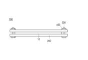

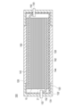
Classifications
-
- H—ELECTRICITY
- H01—ELECTRIC ELEMENTS
- H01M—PROCESSES OR MEANS, e.g. BATTERIES, FOR THE DIRECT CONVERSION OF CHEMICAL ENERGY INTO ELECTRICAL ENERGY
- H01M10/00—Secondary cells; Manufacture thereof
- H01M10/04—Construction or manufacture in general
- H01M10/0468—Compression means for stacks of electrodes and separators
-
- H—ELECTRICITY
- H01—ELECTRIC ELEMENTS
- H01M—PROCESSES OR MEANS, e.g. BATTERIES, FOR THE DIRECT CONVERSION OF CHEMICAL ENERGY INTO ELECTRICAL ENERGY
- H01M10/00—Secondary cells; Manufacture thereof
- H01M10/05—Accumulators with non-aqueous electrolyte
- H01M10/056—Accumulators with non-aqueous electrolyte characterised by the materials used as electrolytes, e.g. mixed inorganic/organic electrolytes
- H01M10/0564—Accumulators with non-aqueous electrolyte characterised by the materials used as electrolytes, e.g. mixed inorganic/organic electrolytes the electrolyte being constituted of organic materials only
- H01M10/0566—Liquid materials
-
- H—ELECTRICITY
- H01—ELECTRIC ELEMENTS
- H01M—PROCESSES OR MEANS, e.g. BATTERIES, FOR THE DIRECT CONVERSION OF CHEMICAL ENERGY INTO ELECTRICAL ENERGY
- H01M10/00—Secondary cells; Manufacture thereof
- H01M10/05—Accumulators with non-aqueous electrolyte
- H01M10/058—Construction or manufacture
- H01M10/0585—Construction or manufacture of accumulators having only flat construction elements, i.e. flat positive electrodes, flat negative electrodes and flat separators
-
- H—ELECTRICITY
- H01—ELECTRIC ELEMENTS
- H01M—PROCESSES OR MEANS, e.g. BATTERIES, FOR THE DIRECT CONVERSION OF CHEMICAL ENERGY INTO ELECTRICAL ENERGY
- H01M4/00—Electrodes
- H01M4/02—Electrodes composed of, or comprising, active material
- H01M4/13—Electrodes for accumulators with non-aqueous electrolyte, e.g. for lithium-accumulators; Processes of manufacture thereof
-
- H—ELECTRICITY
- H01—ELECTRIC ELEMENTS
- H01M—PROCESSES OR MEANS, e.g. BATTERIES, FOR THE DIRECT CONVERSION OF CHEMICAL ENERGY INTO ELECTRICAL ENERGY
- H01M10/00—Secondary cells; Manufacture thereof
- H01M10/04—Construction or manufacture in general
- H01M10/0486—Frames for plates or membranes
-
- H—ELECTRICITY
- H01—ELECTRIC ELEMENTS
- H01M—PROCESSES OR MEANS, e.g. BATTERIES, FOR THE DIRECT CONVERSION OF CHEMICAL ENERGY INTO ELECTRICAL ENERGY
- H01M2220/00—Batteries for particular applications
- H01M2220/20—Batteries in motive systems, e.g. vehicle, ship, plane
-
- H—ELECTRICITY
- H01—ELECTRIC ELEMENTS
- H01M—PROCESSES OR MEANS, e.g. BATTERIES, FOR THE DIRECT CONVERSION OF CHEMICAL ENERGY INTO ELECTRICAL ENERGY
- H01M2300/00—Electrolytes
- H01M2300/0017—Non-aqueous electrolytes
- H01M2300/0025—Organic electrolyte
-
- H—ELECTRICITY
- H01—ELECTRIC ELEMENTS
- H01M—PROCESSES OR MEANS, e.g. BATTERIES, FOR THE DIRECT CONVERSION OF CHEMICAL ENERGY INTO ELECTRICAL ENERGY
- H01M50/00—Constructional details or processes of manufacture of the non-active parts of electrochemical cells other than fuel cells, e.g. hybrid cells
- H01M50/20—Mountings; Secondary casings or frames; Racks, modules or packs; Suspension devices; Shock absorbers; Transport or carrying devices; Holders
- H01M50/204—Racks, modules or packs for multiple batteries or multiple cells
- H01M50/207—Racks, modules or packs for multiple batteries or multiple cells characterised by their shape
- H01M50/209—Racks, modules or packs for multiple batteries or multiple cells characterised by their shape adapted for prismatic or rectangular cells
-
- H—ELECTRICITY
- H01—ELECTRIC ELEMENTS
- H01M—PROCESSES OR MEANS, e.g. BATTERIES, FOR THE DIRECT CONVERSION OF CHEMICAL ENERGY INTO ELECTRICAL ENERGY
- H01M50/00—Constructional details or processes of manufacture of the non-active parts of electrochemical cells other than fuel cells, e.g. hybrid cells
- H01M50/20—Mountings; Secondary casings or frames; Racks, modules or packs; Suspension devices; Shock absorbers; Transport or carrying devices; Holders
- H01M50/204—Racks, modules or packs for multiple batteries or multiple cells
- H01M50/207—Racks, modules or packs for multiple batteries or multiple cells characterised by their shape
- H01M50/211—Racks, modules or packs for multiple batteries or multiple cells characterised by their shape adapted for pouch cells
-
- H—ELECTRICITY
- H01—ELECTRIC ELEMENTS
- H01M—PROCESSES OR MEANS, e.g. BATTERIES, FOR THE DIRECT CONVERSION OF CHEMICAL ENERGY INTO ELECTRICAL ENERGY
- H01M50/00—Constructional details or processes of manufacture of the non-active parts of electrochemical cells other than fuel cells, e.g. hybrid cells
- H01M50/20—Mountings; Secondary casings or frames; Racks, modules or packs; Suspension devices; Shock absorbers; Transport or carrying devices; Holders
- H01M50/233—Mountings; Secondary casings or frames; Racks, modules or packs; Suspension devices; Shock absorbers; Transport or carrying devices; Holders characterised by physical properties of casings or racks, e.g. dimensions
- H01M50/238—Flexibility or foldability
-
- H—ELECTRICITY
- H01—ELECTRIC ELEMENTS
- H01M—PROCESSES OR MEANS, e.g. BATTERIES, FOR THE DIRECT CONVERSION OF CHEMICAL ENERGY INTO ELECTRICAL ENERGY
- H01M50/00—Constructional details or processes of manufacture of the non-active parts of electrochemical cells other than fuel cells, e.g. hybrid cells
- H01M50/20—Mountings; Secondary casings or frames; Racks, modules or packs; Suspension devices; Shock absorbers; Transport or carrying devices; Holders
- H01M50/233—Mountings; Secondary casings or frames; Racks, modules or packs; Suspension devices; Shock absorbers; Transport or carrying devices; Holders characterised by physical properties of casings or racks, e.g. dimensions
- H01M50/242—Mountings; Secondary casings or frames; Racks, modules or packs; Suspension devices; Shock absorbers; Transport or carrying devices; Holders characterised by physical properties of casings or racks, e.g. dimensions adapted for protecting batteries against vibrations, collision impact or swelling
Definitions
- the present invention relates to a battery device.
- Motor drive secondary batteries are required to have extremely high output characteristics and high energy compared to consumer lithium ion secondary batteries used in mobile phones and notebook computers. Therefore, lithium ion secondary batteries having the highest theoretical energy among all practical batteries are attracting attention, and are currently being developed rapidly.
- a non-aqueous electrolyte secondary battery such as a lithium ion secondary battery generally includes a positive electrode obtained by applying a positive electrode active material slurry containing a positive electrode active material and a binder to the surface of a positive electrode current collector and then drying, and a negative electrode active material and a binder.
- a power generation element in which a negative electrode obtained by applying and drying a negative electrode active material slurry containing, for example, on the surface of a negative electrode current collector is connected via an electrolyte layer (a separator holding an electrolyte) is housed in an exterior body. It has a configuration.
- the heating step of crystallizing the binder by drying the electrode active material slurry It was found that cracks may occur in the electrode active material layer. Cracks in the electrode active material layer can cause a significant decrease in battery performance. Therefore, in order to prevent the occurrence of such cracks, the inventors of the present invention have an electrode active material layer (hereinafter simply referred to as “non-bound body”) that is not bound by a binder crystallized by heating.
- non-bound body an electrode active material layer
- the conductivity in the active material layer tends to be lower than that of the dry electrode bound by the binder.
- the internal resistance of the cell when using the non-binding active material layer is sensitive to the applied pressure, and a much larger applied pressure than that of the dry electrode is applied. Without it, it was found that the internal resistance of the cell was not lowered sufficiently.
- the pressure member for pressurizing the cell is enlarged, and the energy density as a battery device including the pressure member is greatly reduced. There is a problem of end up.
- the present invention can reduce the internal resistance of the battery and improve the cycle characteristics in the nonaqueous electrolyte secondary battery using the non-binding active material layer while minimizing the decrease in the energy density of the battery. It aims to provide a means.
- the present inventors have intensively studied to solve the above problems.
- the power generation element is arranged so that the thickness in the stacking direction of the power generation elements varies in the plane direction of the power generation element. It has been found that the above-mentioned problems can be solved by pressurizing in the laminating direction, and the present invention has been completed.
- a positive electrode in which a positive electrode active material layer made of a non-binder including a positive electrode active material is formed on the surface of the positive electrode current collector, and a negative electrode active material on the surface of the negative electrode current collector.
- a nonaqueous electrolyte secondary battery including a power generation element including a negative electrode formed with a negative electrode active material layer made of a non-binder including a substance, and a separator holding an electrolyte; and the power generation element
- a battery device having a pressure member that pressurizes in the stacking direction is provided.
- the said battery apparatus WHEREIN: When the thickness of the hottest part in the lamination direction of the said electric power generation element is set to T1, and the thickness of the thinnest part is set to T2, following numerical formula (1):
- 1 is a cross-sectional view schematically showing a bipolar lithium ion secondary battery according to an embodiment of the present invention.
- 1 is a perspective view of a battery device including a bipolar lithium ion secondary battery according to an embodiment of the present invention. It is the side view seen from the A direction shown in FIG. It is a schematic cross section for demonstrating the characteristic of the battery apparatus which concerns on this invention. It is a schematic cross section for demonstrating other embodiment of the battery apparatus which concerns on this form.
- One embodiment of the present invention includes a positive electrode in which a positive electrode active material layer including a non-binder including a positive electrode active material is formed on the surface of a positive electrode current collector, and a non-electrode including a negative electrode active material on the surface of the negative electrode current collector.
- a non-aqueous electrolyte secondary battery including a power generation element including a negative electrode on which a negative electrode active material layer made of a binder is formed, and a separator holding an electrolytic solution, and the power generation element in the stacking direction.
- the present invention relates to a battery device that satisfies According to the battery device having such a configuration, the non-binding active material layer pressurized in the stacking direction of the power generation elements flows, whereby the pressure inside the active material layer can be made uniform. Therefore, even if a large pressing force is not uniformly applied to the power generation element (that is, a large pressure member that reduces the energy density is not disposed), the internal resistance of the battery is reduced and the cycle characteristics are improved. It becomes possible to make it.
- bipolar lithium ion secondary battery may be simply referred to as “bipolar secondary battery”, and the electrode for the bipolar lithium ion secondary battery may be simply referred to as “bipolar electrode”.
- FIG. 1 is a cross-sectional view schematically showing a bipolar lithium ion secondary battery according to an embodiment of the present invention.
- the bipolar lithium ion secondary battery 10 shown in FIG. 1 has a structure in which a substantially rectangular power generation element 21 in which a charge / discharge reaction actually proceeds is sealed inside a laminate film 29 that is an exterior body.
- the power generation element 21 of the bipolar lithium ion secondary battery 10 includes a positive electrode active material layer 13 that is electrically coupled to one surface of the current collector 11.
- 11 has a plurality of bipolar electrodes 23 formed with a negative electrode active material layer 15 electrically coupled to the opposite surface.
- Each bipolar electrode 23 is laminated via a separator 17 (electrolyte layer) holding an electrolytic solution to form a power generation element 21.
- the positive electrode active material layer 13 of one bipolar electrode 23 and the negative electrode active material layer 15 of another bipolar electrode 23 adjacent to the one bipolar electrode 23 face each other through the separator 17.
- Bipolar electrodes 23 and separators 17 are alternately stacked.
- the separator 17 is interposed between the positive electrode active material layer 13 of one bipolar electrode 23 and the negative electrode active material layer 15 of another bipolar electrode 23 adjacent to the one bipolar electrode 23.
- the negative electrode active material layer 15 is formed to be slightly larger than the positive electrode active material layer 13 when viewed from the stacking direction of the power generation elements 21.
- the technical scope of the present invention is not limited to the bipolar secondary battery as shown in FIG. 1, and a plurality of single battery layers as disclosed in, for example, International Publication No. 2016/031688 are electrically used. As a result of being stacked in series, a battery having a similar series connection structure may be used.
- the negative electrode active material layer 15 functions as a negative electrode of the secondary battery by including the negative electrode active material.
- the negative electrode active material layer 15 may include carbon fibers that are conductive fibers as a conductive member.
- the first main surface contacting the electrolyte layer 17 side of the negative electrode active material layer 15 is electrically connected to the second main surface contacting the current collector 11 side.
- a conductive path can be formed, and the conductive path and the negative electrode active material can be electrically connected.
- the positive electrode active material layer 13 may include carbon fibers that are conductive fibers as a conductive member.
- the positive electrode active material layer 13 includes carbon fibers, the conductive material that electrically connects the first main surface that contacts the separator 17 side of the positive electrode active material layer 13 to the second main surface that contacts the current collector 11 side.
- a passage can be formed, and the conductive passage and the negative electrode active material can be electrically connected.
- the negative electrode active material layer 15 and the positive electrode active material layer 13 do not contain a binder contained in an active material layer of a general nonaqueous electrolyte secondary battery (that is, a “non-binding body”).
- the adjacent positive electrode active material layer 13, separator 17, and negative electrode active material layer 15 constitute one unit cell layer 19. Therefore, it can be said that the bipolar lithium ion secondary battery 10 has a configuration in which the single battery layers 19 are stacked.
- a seal portion (insulating layer) 31 is disposed on the outer peripheral portion of the unit cell layer 19.
- a positive electrode active material layer 13 is formed only on one side of the positive electrode outermost layer current collector 11 a located in the outermost layer of the power generation element 21.
- the negative electrode active material layer 15 is formed only on one surface of the outermost current collector 11b on the negative electrode side located in the outermost layer of the power generation element 21.
- a positive electrode current collector plate (positive electrode tab) 25 is disposed adjacent to the outermost layer current collector 11a on the positive electrode side, and this is extended to provide an outer package. Derived from a certain laminate film 29.
- a negative electrode current collector plate (negative electrode tab) 27 is disposed so as to be adjacent to the outermost layer current collector 11 b on the negative electrode side, and is similarly extended and led out from the laminate film 29.
- the number of times the single battery layer 19 is stacked is adjusted according to the desired voltage.
- the number of stacks of the single battery layers 19 may be reduced if a sufficient output can be secured even if the thickness of the battery is reduced as much as possible.
- the power generation element 21 is sealed under reduced pressure in a laminate film 29 that is an exterior body, and the positive current collector plate 25 and the negative electrode It is preferable that the current collecting plate 27 is taken out of the laminate film 29.
- FIG. 2 is a perspective view of a battery device including a bipolar lithium ion secondary battery according to an embodiment of the present invention.
- FIG. 3 is a side view seen from the direction A shown in FIG.
- the battery device 100 including the bipolar lithium ion secondary battery includes the bipolar lithium ion secondary battery 10 and the bipolar lithium ion secondary battery 10 shown in FIG. 1. It has two metal plates 200 to be sandwiched, and a bolt 300 and a nut 400 as fastening members.
- the fastening members (bolts 300 and nuts 400) have a function of fixing the metal plate 200 while sandwiching the bipolar lithium ion secondary battery 10.
- the metal plate 200 and the fastening member function as a pressurizing member that pressurizes the power generating element 21 provided in the bipolar lithium ion secondary battery 10 in the stacking direction.
- a pressurization member is a member which can pressurize the electric power generation element 21 with which the bipolar lithium ion secondary battery 10 is provided in the lamination direction, it will not be restrict
- the pressure member typically, a combination of a plate formed of a material having rigidity such as the metal plate 200 and the above-described fastening member is used.
- the fastening member not only the bolt 300 and the nut 400 but also a tension plate that fixes the end of the metal plate 200 so as to pressurize the power generation element 21 in the stacking direction may be used.
- FIG. 4 is a schematic cross-sectional view for explaining the characteristics of the battery device according to the present invention.
- the power generation element 21 of the nonaqueous electrolyte secondary battery constituting the battery device according to the present invention is pressurized by a pressure member (a pair of metal plates 200).
- a pressure member a pair of metal plates 200
- the thickness of the power generation element 21 varies in the surface direction of the power generation element.
- the “thickness of the power generation element 21” refers to an active material positioned in both outermost layers of the power generation element in the facing portion between the positive electrode active material layer 13 and the negative electrode active material layer 15 constituting the power generation element. It shall mean the distance (in the stacking direction of the power generation elements) between the outermost surfaces of the layers.
- the variation in the thickness of the power generation element 21 is controlled within a predetermined range. That is, when the thickness of the thickest portion in the stacking direction of the power generation elements 21 is T1, and the thickness of the thinnest portion is T2, the following formula (1):
- the battery device has the following mathematical formula (2):
- the battery device has the following mathematical formula (3):
- the battery performance can be further improved.
- a specific method for configuring the battery device so as to satisfy the above formulas (1) to (3) and the arrangement of the pressure members is controlled or a fastening member is used.
- whether or not the thickness of the power generation element 21 satisfies the above-described formulas (1) to (3) is determined using a non-X-ray CT apparatus described in the column of an example described later, for example. This can be done by a destructive technique.
- this determination may be made by a destructive method as long as the same values of T1 and T2 as those obtained by using a nondestructive method such as X-ray CT can be obtained.
- a destructive method such as X-ray CT
- a battery module formed by stacking a plurality of batteries in which a power generation element is sealed in an exterior body may constitute a battery device together with a pressure member.
- the battery is included in the technical scope of the present invention as long as at least one of the batteries constituting the battery module satisfies the relationship expressed by the above formula (1).
- the present inventors have collected non-binding active material layers that are not bound by a binder. We studied the use of electrodes placed on the surface of the body.
- the conductivity in the active material layer tends to be lower than that of the dry electrode bound by the binder.
- the internal resistance of the cell when using the non-binding active material layer is sensitive to the applied pressure, and a much larger applied pressure than that of the dry electrode is applied. Without it, it was found that the internal resistance of the cell was not lowered sufficiently.
- the constituent components of the active material layer in the dry electrode are bound by the binder, there is almost no sensitivity to the applied pressure, and an increase in internal resistance can be suppressed even with a relatively small applied pressure.
- the pressure member for pressurizing the cell is enlarged, and the energy density as a battery device including the pressure member is greatly increased. There is a problem that it falls.
- the problem can be solved. That is, the present inventors surprisingly have the configuration according to the present invention, so that a large amount of pressure that causes a decrease in energy density can be obtained even when a large pressure is not uniformly applied to the power generating element. It has further been found that even if no pressure member is provided, the internal resistance of the battery can be reduced and the cycle characteristics can be improved. This is because, according to the battery device that satisfies the above formula (1), the non-binding active material layer pressurized in the stacking direction of the power generation elements can flow to make the pressure inside the active material layer uniform. It is estimated that
- the minimum value (minimum load) of the load applied to the power generation element 21 is preferably 20 kPa or more, and more preferably 200 kPa or more. By adopting such a configuration, the effects of the present invention can be expressed more remarkably.
- the “pressing force in the stacking direction of the power generation elements” is not always constant and may vary depending on the part.
- the “minimum value (minimum load) of the applied pressure in the stacking direction of the power generation elements” means the smallest value of the applied pressure (load) that varies depending on the part.
- the said upper limit is preferably 250 kPa or less.
- the current collector has a function of mediating transfer of electrons from one surface in contact with the positive electrode active material layer to the other surface in contact with the negative electrode active material layer.
- the current collector may include a resin layer having conductivity (so-called “resin current collector”).
- examples of the metal include aluminum, nickel, iron, stainless steel, titanium, and copper.
- a clad material of nickel and aluminum, a clad material of copper and aluminum, and the like can be preferably used.
- covered on the metal surface may be sufficient.
- aluminum, stainless steel, copper, and nickel are preferable from the viewpoints of electronic conductivity, battery operating potential, and adhesion of the negative electrode active material by sputtering to the current collector.
- a resin in which a conductive filler is added to a conductive polymer material or a non-conductive polymer material as necessary is used.
- the conductive polymer material include polyaniline, polypyrrole, polythiophene, polyacetylene, polyparaphenylene, polyphenylene vinylene, polyacrylonitrile, and polyoxadiazole. Since such a conductive polymer material has sufficient conductivity without adding a conductive filler, it is advantageous in terms of facilitating the manufacturing process or reducing the weight of the current collector.
- Non-conductive polymer materials include, for example, polyethylene (PE; high density polyethylene (HDPE), low density polyethylene (LDPE), etc.), polypropylene (PP), polyethylene terephthalate (PET), polyether nitrile (PEN), polyimide (PI), polyamideimide (PAI), polyamide (PA), polytetrafluoroethylene (PTFE), styrene-butadiene rubber (SBR), polyacrylonitrile (PAN), polymethyl acrylate (PMA), polymethyl methacrylate (PMMA) , Polyvinyl chloride (PVC), polyvinylidene fluoride (PVdF), or polystyrene (PS).
- PE polyethylene
- HDPE high density polyethylene
- LDPE low density polyethylene
- PP polypropylene
- PET polyethylene terephthalate
- PEN polyether nitrile
- PI polyimide
- PAI polyamideimide
- PA polyamide
- PTFE polytetraflu
- a conductive filler may be added to the conductive polymer material or the non-conductive polymer material as necessary.
- a conductive filler is inevitably necessary to impart conductivity to the resin.
- the conductive filler can be used without particular limitation as long as it has a conductivity.
- metals, conductive carbon, etc. are mentioned as a material excellent in electroconductivity, electric potential resistance, or lithium ion barrier
- the metal is not particularly limited, but at least one metal selected from the group consisting of Ni, Ti, Al, Cu, Pt, Fe, Cr, Sn, Zn, In, Sb, and K, or these metals It is preferable to contain an alloy or metal oxide containing. Moreover, there is no restriction
- acetylene black Vulcan (registered trademark), black pearl (registered trademark), carbon nanofiber, ketjen black (registered trademark), carbon nanotube, carbon nanohorn, carbon nanoballoon, and fullerene. It contains at least one kind.
- the amount of the conductive filler added is not particularly limited as long as it is an amount that can impart sufficient conductivity to the current collector, and is generally about 5 to 35% by volume.
- the current collector of this embodiment may have a single-layer structure made of a single material, or may have a laminated structure in which layers made of these materials are appropriately combined. From the viewpoint of reducing the weight of the current collector, it is preferable to include a conductive resin layer made of at least a conductive resin. Further, from the viewpoint of blocking the movement of lithium ions between the unit cell layers, a metal layer may be provided on a part of the current collector.
- the thickness of the current collector is not particularly limited, but is preferably 50 to 100 ⁇ m.
- the positive electrode active material layer includes a positive electrode active material and, if necessary, a coating agent that covers the surface of the positive electrode active material. Further, the positive electrode active material layer may further contain a conductive member, an ion conductive polymer, a lithium salt, or the like as necessary.
- the positive electrode active material coated with a coating agent is also referred to as “coated positive electrode active material particles”.
- the coated positive electrode active material particles have a core-shell structure in which a shell portion made of a coating agent containing a coating resin and a conductive additive is formed on the surface of the core portion made of the positive electrode active material.
- the positive electrode active material examples include LiMn 2 O 4 , LiCoO 2 , LiNiO 2 , Li (Ni—Mn—Co) O 2, and lithium-- such as those in which some of these transition metals are substituted with other elements.
- Examples include transition metal composite oxides, lithium-transition metal phosphate compounds, and lithium-transition metal sulfate compounds.
- two or more positive electrode active materials may be used in combination.
- a lithium-transition metal composite oxide is used as the positive electrode active material. More preferably, a composite oxide containing lithium and nickel is used.
- NMC composite oxide Li (Ni—Mn—Co) O 2 and a part of these transition metals substituted with other elements
- NMC composite oxide lithium-nickel-cobalt -Aluminum composite oxide
- the NMC composite oxide has a layered crystal structure in which lithium atomic layers and transition metal (Mn, Ni, and Co are arranged in order) atomic layers are alternately stacked via oxygen atomic layers.
- one Li atom is contained per one atom of the transition metal M, and the amount of Li that can be taken out is twice that of the spinel-based lithium manganese oxide, that is, the supply capacity is doubled, so that a high capacity can be obtained.
- the NMC composite oxide includes a composite oxide in which a part of the transition metal element is substituted with another metal element.
- Other elements in that case include Ti, Zr, Nb, W, P, Al, Mg, V, Ca, Sr, Cr, Fe, B, Ga, In, Si, Mo, Y, Sn, V, Cu , Ag, Zn, etc., preferably Ti, Zr, Nb, W, P, Al, Mg, V, Ca, Sr, Cr, more preferably Ti, Zr, P, Al, Mg, From the viewpoint of improving cycle characteristics, Ti, Zr, Al, Mg, and Cr are more preferable.
- a represents the atomic ratio of Li
- b represents the atomic ratio of Ni
- c represents the atomic ratio of Mn
- d represents the atomic ratio of Co
- x represents the atomic ratio of M. Represents. From the viewpoint of cycle characteristics, it is preferable that 0.4 ⁇ b ⁇ 0.6 in the general formula (1).
- the composition of each element can be measured by, for example, inductively coupled plasma (ICP) emission spectrometry.
- ICP inductively coupled plasma
- Ni nickel
- Co cobalt
- Mn manganese
- Ti or the like partially replaces the transition metal in the crystal lattice. From the viewpoint of cycle characteristics, it is preferable that a part of the transition element is substituted with another metal element, and it is particularly preferable that 0 ⁇ x ⁇ 0.3 in the general formula (1). Since at least one selected from the group consisting of Ti, Zr, Nb, W, P, Al, Mg, V, Ca, Sr, and Cr is dissolved, the crystal structure is stabilized. It is considered that the battery capacity can be prevented from decreasing even if the above is repeated, and that excellent cycle characteristics can be realized.
- b, c and d are 0.44 ⁇ b ⁇ 0.51, 0.27 ⁇ c ⁇ 0.31, 0.19 ⁇ d ⁇ 0.26. It is preferable from the viewpoint of improving the balance between capacity and life characteristics.
- LiNi 0.5 Mn 0.3 Co 0.2 O 2 is LiCoO 2 , LiMn 2 O 4 , LiNi 1/3 Mn 1/3 Co 1/3 O 2, etc. that have been proven in general consumer batteries. Compared with, the capacity per unit weight is large. Thereby, the energy density can be improved, and it has an advantage that a compact and high-capacity battery can be produced, which is preferable from the viewpoint of cruising distance.
- LiNi 0.8 Co 0.1 Al 0.1 O 2 is more advantageous in terms of a larger capacity, but there are difficulties in life characteristics.
- LiNi 0.5 Mn 0.3 Co 0.2 O 2 has life characteristics as excellent as LiNi 1/3 Mn 1/3 Co 1/3 O 2 .
- the average particle size of the positive electrode active material is not particularly limited, but is preferably 1 to 100 ⁇ m, more preferably 1 to 20 ⁇ m from the viewpoint of increasing the output.
- the coating agent contains a coating resin and a conductive additive. When the coating agent is present on the surface of the positive electrode active material, an ion conduction path and an electron conduction path to the surface of the positive electrode active material can be secured in the positive electrode active material layer.
- the coating resin is present on the surface of the positive electrode active material and has a function of absorbing and holding the electrolytic solution. Thereby, in the positive electrode active material layer, an ion conduction path from the electrolyte layer to the surface of the positive electrode active material can be formed.
- the material of the coating resin is not particularly limited, but is selected from the group consisting of (A) polyurethane resin and (B) polyvinyl resin from the viewpoint of flexibility and liquid absorption. It is preferable to contain at least one kind.
- Polyurethane resin has high flexibility (large tensile elongation at break described later), and since urethane bonds can form strong hydrogen bonds, it can be used as a coating resin. It is possible to form a structurally stable coating agent that is excellent in flexibility.
- the polyurethane resin is composed of (a1) a polyisocyanate component and (a2) a polyol component, and (a3) an ionic group-introducing component, (a4) an ionic group neutralizing agent component, and (a5) a chain extension as necessary. You may comprise using an agent component further.
- polyisocyanate component examples include a diisocyanate compound having two isocyanate groups in one molecule and a polyisocyanate compound having three or more isocyanate groups in one molecule. These may be used alone or in combination of two or more.
- Diisocyanate compounds include 4,4'-diphenylmethane diisocyanate (MDI), 2,4- and / or 2,6-tolylene diisocyanate, p-phenylene diisocyanate, xylylene diisocyanate, 1,5-naphthalene diisocyanate, 3,3 Aromatic diisocyanates such as' -dimethyldiphenyl-4,4'-diisocyanate, dianisidine diisocyanate, tetramethylxylylene diisocyanate; isophorone diisocyanate, dicyclohexylmethane-4,4'-diisocyanate, trans-1,4-cyclohexyl diisocyanate, norbornene Cycloaliphatic diisocyanates such as diisocyanates; 1,6-hexamethylene diisocyanate, 2,2,4 and / or (2,4,4) -trimethyl Examples thereof include aliphatic diisocyanates such as
- diisocyanate compounds may be used in the form of modified products such as carbodiimide modification, isocyanurate modification, biuret modification, etc., or may be used in the form of blocked isocyanates blocked with various blocking agents.
- polyisocyanate compounds having three or more isocyanate groups in one molecule include, for example, isocyanurate trimers, biuret trimers, trimethylolpropane adducts of diisocyanates exemplified above; triphenylmethane triisocyanate, 1- Examples thereof include trifunctional or higher functional isocyanates such as methylbenzole-2,4,6-triisocyanate and dimethyltriphenylmethanetetraisocyanate.
- isocyanate compounds are in the form of modified products such as carbodiimide modification, isocyanurate modification, biuret modification and the like. It may be used in the form of a blocked isocyanate blocked with various blocking agents.
- polyol component examples include a diol compound having two hydroxyl groups in one molecule and a polyol compound having three or more hydroxyl groups in one molecule, and these may be used alone. Two or more kinds may be used in combination.
- diol compound and the polyol compound having three or more hydroxyl groups in one molecule examples include low molecular weight polyols, polyether polyols, polyester polyols, polyester polycarbonate polyols, crystalline or non-crystalline polycarbonate polyols, and polybutadiene.
- a polyol and a silicone polyol are mentioned.
- low molecular polyols examples include ethylene glycol, 1,2-propanediol, 1,3-propanediol, 2-methyl-1,3-propanediol, and 2-butyl-2-ethyl-1,3-propane.
- polyether polyols examples include ethylene oxide adducts such as diethylene glycol, triethylene glycol, tetraethylene glycol, and polyethylene glycol; propylene oxide adducts such as dipropylene glycol, tripropylene glycol, tetrapropylene glycol, and polypropylene glycol; These include low molecular weight polyol ethylene oxide and / or propylene oxide adducts, polytetramethylene glycol and the like.
- polyester polyols include polyols such as the low molecular weight polyols exemplified above, and ester-forming derivatives such as polycarboxylic acids or their esters, anhydrides, halides, and the like in an amount less than the stoichiometric amount, and / or Examples thereof include those obtained by a direct esterification reaction and / or a transesterification reaction with a lactone or a hydroxycarboxylic acid obtained by hydrolytic ring-opening thereof.
- polycarboxylic acids or ester-forming derivatives thereof include oxalic acid, malonic acid, succinic acid, glutaric acid, adipic acid, pimelic acid, suberic acid, azelaic acid, sebacic acid, dodecanedioic acid, 2-methylsuccinic acid 2-methyladipic acid, 3-methyladipic acid, 3-methylpentanedioic acid, 2-methyloctanedioic acid, 3,8-dimethyldecanedioic acid, 3,7-dimethyldecanedioic acid, hydrogenated dimer acid, Aliphatic dicarboxylic acids such as dimer acid; aromatic dicarboxylic acids such as phthalic acid, terephthalic acid, isophthalic acid and naphthalenedicarboxylic acid; alicyclic dicarboxylic acids such as cyclohexanedicarboxylic acid; trimeric acid, trimesic acid, castor oil fatty acid Poly
- Examples include lower aliphatic esters such as esters, butyl esters, isobutyl esters, and amyl esters.
- Examples of the lactones include lactones such as ⁇ -caprolactone, ⁇ -caprolactone, ⁇ -caprolactone, dimethyl- ⁇ -caprolactone, ⁇ -valerolactone, ⁇ -valerolactone, and ⁇ -butyrolactone.
- An ionic group-introducing component used as necessary includes an anionic group-introducing component and a cationic group-introducing component.
- the anionic group to be introduced include polyols containing a carboxyl group such as dimethylolpropionic acid, dimethylolbutanoic acid, dimethylolbutyric acid, dimethylolvaleric acid, 1,4-butanediol-2-sulfonic acid, etc.
- Polyols containing a sulfonic acid group of, for example, those for introducing a cationic group include N, N-dialkylalkanolamines, N-methyl-N, N-diethanolamine, N-butyl-N, N-alkyl-N, N-dialkanolamines such as N-diethanolamine and trialkanolamines can be mentioned.
- the (a4) ionic group neutralizing agent component used as required includes anionic group neutralizing agents such as trialkylamines such as trimethylamine, triethylamine, and tributylamine, N, N-dimethylethanolamine, N N, N-dimethylpropanolamine, N, N-dipropylethanolamine, N, N-dialkylalkanolamines such as 1-dimethylamino-2-methyl-2-propanol, N-alkyl-N, N-dialkanolamine , Tertiary amine compounds such as trialkanolamines such as triethanolamine; basic compounds such as ammonia, trimethylammonium hydroxide, sodium hydroxide, potassium hydroxide, lithium hydroxide, etc., neutralizing cationic groups Agents include formic acid, acetic acid, lactic acid, succinic acid, Organic carboxylic acids such as phosphoric acid and citric acid, organic sulfonic acids such as paratoluenesulfonic acid
- polyvalent amine compound examples include low molecular diamines in which the alcoholic hydroxyl groups of the above-illustrated low molecular diols such as ethylenediamine and propylenediamine are substituted with amino groups; polyethers such as polyoxypropylenediamine and polyoxyethylenediamine Diamines; mensendiamine, isophoronediamine, norbornenediamine, bis (4-amino-3-methyldicyclohexyl) methane, diaminodicyclohexylmethane, bis (aminomethyl) cyclohexane, 3,9-bis (3-aminopropyl) 2, Cycloaliphatic diamines such as 4,8,10-tetraoxaspiro (5,5) undecane;
- a diisocyanate compound as the (a1) polyisocyanate component, and 4,4′-diphenylmethane diisocyanate (MDI), 2,4′-diphenylmethane diisocyanate, 4,4′-dicyclohexyl. It is particularly preferable to use methane diisocyanate, 1,4-cyclohexane diisocyanate, 2,4-toluene diisocyanate, 1,6-hexamethylene diisocyanate, and most preferably 4,4′-diphenylmethane diisocyanate (MDI).
- MDI 4,4′-diphenylmethane diisocyanate
- the (a2) polyol component it is preferable to use an ethylene oxide adduct that is a diol compound, and it is particularly preferable to use polyethylene glycol as an essential component. Since polyethylene glycol is excellent in lithium ion conductivity, the effect of reducing (raising suppression) the internal resistance of the battery can be remarkably exhibited by adopting such a configuration.
- the number average molecular weight calculated from the hydroxyl value of polyethylene glycol is not particularly limited, but is preferably 2,500 to 15,000, more preferably 3,000 to 13,000, and still more preferably 3 , 500 to 10,000.
- ethylene glycol and / or glycerin as the polyol component in addition to the essential components described above.
- the gel obtained by swelling the coating resin becomes a physical cross-linked gel, which can be dissolved in a solvent at the time of production, and various productions as described later. The method can be applied.
- the main chains of the polyurethane resin are chemically cross-linked. In this case, the degree of swelling into the electrolyte can be controlled arbitrarily by controlling the molecular weight between the cross-links.
- the specific form of the polyvinyl resin is not particularly limited, and may be a polymer obtained by polymerizing a monomer containing a monomer having a polymerizable unsaturated bond (hereinafter also referred to as “vinyl monomer”).
- a monomer containing a monomer having a polymerizable unsaturated bond hereinafter also referred to as “vinyl monomer”.
- vinyl monomer a monomer containing a monomer having a polymerizable unsaturated bond
- conventionally known knowledge can be referred to as appropriate.
- the vinyl monomer includes a vinyl monomer (b1) having a carboxyl group and a vinyl monomer (b2) represented by the following general formula (1).
- R 1 is a hydrogen atom or a methyl group
- R 2 is a linear alkyl group having 1 to 4 carbon atoms or a branched alkyl group having 4 to 36 carbon atoms.
- Examples of the vinyl monomer having a carboxyl group (b1) include monocarboxylic acids having 3 to 15 carbon atoms such as (meth) acrylic acid, crotonic acid, cinnamic acid; (anhydrous) maleic acid, fumaric acid, (anhydrous) itaconic acid, Examples thereof include dicarboxylic acids having 4 to 24 carbon atoms such as citraconic acid and mesaconic acid; polycarboxylic acids having 6 to 24 carbon atoms such as aconitic acid and having valences of 4 to 24 or more.
- (meth) acrylic acid is preferable, and methacrylic acid is particularly preferable.
- R 1 represents a hydrogen atom or a methyl group.
- R 1 is preferably a methyl group.
- R 2 is a linear alkyl group having 1 to 4 carbon atoms or a branched alkyl group having 4 to 36 carbon atoms. Specific examples of R 2 include a methyl group, an ethyl group, a propyl group, and a 1-alkylalkyl group.
- a methyl group, an ethyl group, and a 2-alkylalkyl group are preferable from the viewpoint of absorbing the electrolyte solution, and a 2-ethylhexyl group and a 2-decyltetradecyl group are more preferable.
- the monomer constituting the polymer includes a vinyl monomer (b1) having a carboxyl group, a vinyl monomer (b2) represented by the above general formula (1), and a copolymerization property containing no active hydrogen.
- a vinyl monomer (b3) may be contained.
- Examples of the copolymerizable vinyl monomer (b3) containing no active hydrogen include the following (b31) to (b35).
- the monool includes (i) aliphatic monool [methanol, ethanol, n- and i-propyl.
- Alcohol n-butyl alcohol, n-pentyl alcohol, n-octyl alcohol, nonyl alcohol, decyl alcohol, lauryl alcohol, tridecyl alcohol, myristyl alcohol, cetyl alcohol, stearyl alcohol, etc.], (ii) alicyclic monool [ Cyclohexyl alcohol etc.], (iii) araliphatic monools [benzyl alcohol etc.] and mixtures of two or more thereof.
- (B32) Poly (n 2 to 30) oxyalkylene (carbon number 2 to 4) alkyl (carbon number 1 to 18) ether (meth) acrylate [methanol ethylene oxide (hereinafter abbreviated as EO) 10 mol adduct (meth) Acrylate, propylene oxide of methanol (hereinafter abbreviated as PO), 10 mol adduct (meth) acrylate, etc.]
- Nitrogen-containing vinyl compound (b33-1) Amido group-containing vinyl compound (i) (Meth) acrylamide compound having 3 to 30 carbon atoms, such as N, N-dialkyl (1 to 6 carbon atoms) or diaralkyl (carbon number) 7 to 15) (meth) acrylamide [N, N-dimethylacrylamide, N, N-dibenzylacrylamide, etc.], diacetone acrylamide (ii) Contains amide group having 4 to 20 carbon atoms excluding the above (meth) acrylamide compound
- (b34-2) Alicyclic vinyl hydrocarbon Carbon 4-18 or more cyclic unsaturated compounds such as cycloalkenes (e.g. cyclohexene), (di) cycloalkadiene [e.g. (di) cyclopentadiene, terpenes (e.g.
- Aromatic vinyl hydrocarbon Aromatic unsaturated compounds having 8 to 20 or more carbon atoms, such as styrene, ⁇ -methylstyrene, vinyltoluene, 2,4-dimethylstyrene, ethylstyrene, isopropylstyrene, butyl Styrene, phenyl styrene, cyclohexyl styrene, benzyl styrene (b35) vinyl ester, vinyl ether, vinyl ketone, unsaturated dicarboxylic acid diester (b35-1) vinyl ester aliphatic vinyl ester [carbon number of 4 to 15, for example, aliphatic carboxylic acid (mono -And dicarboxylic acid) alkenyl esters (eg vinyl acetate, vinyl propionate, vinyl butyrate, diallyl adipate, isopropenyl esters (eg vinyl acetate, vinyl propionate, vinyl but
- vinyl benzoate diallyl phthalate, methyl 4-vinyl benzoate
- an aromatic ring-containing esters of aliphatic carboxylic acids e.g. acetoxystyrene
- the content of the vinyl monomer (b1) having a carboxyl group, the vinyl monomer (b2) represented by the general formula (1) and the copolymerizable vinyl monomer (b3) not containing active hydrogen is determined by the polymer.
- (B1) is preferably 0.1 to 80% by mass
- (b2) is preferably 0.1 to 99.9% by mass
- (b3) is preferably 0 to 99.8% by mass.
- the liquid absorbency to the electrolyte is good.
- More preferable content is 30 to 60% by mass of (b1), 5 to 60% by mass of (b2), and 5 to 80% by mass of (b3). Further preferable content is 35 to 60% of (b1). 50% by mass, (b2) is 15 to 45% by mass, and (b3) is 20 to 60% by mass.
- the preferred lower limit of the number average molecular weight of the polymer is 10,000, more preferably 15,000, particularly preferably 20,000, most preferably 30,000, and the preferred upper limit is 2,000,000, more preferably 1. 500,000, particularly preferably 1,000,000, most preferably 800,000.
- the number average molecular weight of the polymer can be determined by GPC (gel permeation chromatography) measurement under the following conditions.
- Apparatus Alliance GPC V2000 (manufactured by Waters) Solvent: Orthodichlorobenzene Standard substance: Polystyrene Sample concentration: 3 mg / ml Column stationary phase: PLgel 10 ⁇ m, MIXED-B 2 in series (manufactured by Polymer Laboratories) Column temperature: 135 ° C.
- the solubility parameter (SP value) of the polymer is preferably 9.0 to 20.0 (cal / cm 3 ) 1/2 .
- the SP value of the polymer is more preferably 9.5 to 18.0 (cal / cm 3 ) 1/2 , and further preferably 10.0 to 14.0 (cal / cm 3 ) 1/2. preferable.
- the SP value of the polymer is preferably 9.0 to 20.0 (cal / cm 3 ) 1/2 in view of the absorption of the electrolytic solution.
- the glass transition point of the polymer is preferably 80 to 200 ° C., more preferably 90 to 190 ° C. from the viewpoint of heat resistance of the battery. Particularly preferred is 100 to 180 ° C.
- the polymer can be produced by a known polymerization method (bulk polymerization, solution polymerization, emulsion polymerization, suspension polymerization, etc.).
- the coating resin has appropriate flexibility when immersed in an electrolytic solution.
- the tensile elongation at break in the saturated liquid absorption state of the coating resin is preferably 10% or more, more preferably 20% or more, still more preferably 30% or more, and particularly preferably It is 40% or more, and most preferably 50% or more.
- the “tensile elongation at break” is an index indicating the flexibility of the resin, and is a value obtained by the measurement method described in the column of Examples described later.
- the value of the tensile elongation at break of the coating resin is preferably as large as possible, and the upper limit is not particularly limited, but is usually 400% or less, preferably 300% or less. That is, preferable numerical ranges of the tensile elongation at break are 10 to 400%, 20 to 400%, 30 to 400%, 40 to 400%, 50 to 400%, 10 to 300%, 20 to 300%, 30 to 300%, 40-300%, 50-300%.
- a flexible partial structure for example, a long-chain alkyl group, a polyether residue, an alkyl polycarbonate residue, A method of introducing an alkyl polyester residue or the like into the main chain of the coating resin.
- the conductive auxiliary agent can contribute to improving the output characteristics at a high rate of the battery by forming an electron conduction path in the coating agent and reducing the electron transfer resistance of the positive electrode active material layer.
- Examples of the conductive assistant include metals such as aluminum, stainless steel (SUS), silver, gold, copper, and titanium, alloys or metal oxides containing these metals; graphite, carbon fiber (specifically, vapor phase growth) Carbon such as carbon fiber (VGCF), carbon nanotube (CNT), carbon black (specifically, acetylene black, ketjen black (registered trademark), furnace black, channel black, thermal lamp black, etc.).
- metals such as aluminum, stainless steel (SUS), silver, gold, copper, and titanium, alloys or metal oxides containing these metals
- graphite carbon fiber (specifically, vapor phase growth) Carbon such as carbon fiber (VGCF), carbon nanotube (CNT), carbon black (specifically, acetylene black, ketjen black (registered trademark), furnace black, channel black, thermal lamp black, etc.).
- VGCF carbon fiber
- CNT carbon nanotube
- carbon black specifically, acetylene black, ketjen black (registered trademark)
- furnace black channel
- conductive assistants from the viewpoint of electrical stability, it is preferable to include at least one selected from the group consisting of aluminum, stainless steel, silver, gold, copper, titanium, and carbon. More preferably, it contains at least one selected from the group consisting of silver, gold, and carbon, and more preferably contains at least one carbon. These conductive assistants may be used alone or in combination of two or more.
- the shape of the conductive auxiliary agent is preferably particulate or fibrous.
- the shape of the particles is not particularly limited, and may be any shape such as powder, sphere, rod, needle, plate, column, indefinite shape, flake shape, and spindle shape. It doesn't matter.
- the average particle size (primary particle size) when the conductive additive is in the form of particles is not particularly limited, but is preferably about 0.01 to 10 ⁇ m from the viewpoint of the electric characteristics of the battery.
- the “particle diameter” means the maximum distance L among the distances between any two points on the contour line of the conductive additive.
- the value of “average particle size” is the average value of the particle size of particles observed in several to several tens of fields using an observation means such as a scanning electron microscope (SEM) or a transmission electron microscope (TEM). The calculated value shall be adopted.
- a covering positive electrode active material particle is not restrict
- a solution containing a coating resin and a solvent (coating resin solution) is dropped and mixed over 1 to 90 minutes.
- the solvent in this case, alcohols such as methanol, ethanol and isopropanol can be preferably used.
- a conductive additive is further added and mixed.
- the temperature is raised to 50 to 200 ° C. with stirring, the pressure is reduced to 0.007 to 0.04 MPa, and then held for 10 to 150 minutes, whereby coated positive electrode active material particles can be obtained.
- the conductive member has a function of forming an electron conduction path in the positive electrode active material layer.
- at least a part of the conductive member forms a conductive path that electrically connects the first main surface that contacts the electrolyte layer side of the positive electrode active material layer to the second main surface that contacts the current collector side. It is preferable.
- the conductive member forms a conductive passage that electrically connects the first main surface that contacts the electrolyte layer side of the positive electrode active material layer to the second main surface that contacts the current collector side It can be confirmed by observing the cross section of the positive electrode active material layer using an SEM or an optical microscope.
- the conductive member is preferably a conductive fiber having a fibrous form.
- carbon fibers such as PAN-based carbon fibers and pitch-based carbon fibers, conductive fibers obtained by uniformly dispersing highly conductive metal or graphite in synthetic fibers, and metals such as stainless steel.
- Metal fibers conductive fibers obtained by coating the surfaces of organic fibers with metal, conductive fibers obtained by coating the surfaces of organic fibers with a resin containing a conductive substance, and the like.
- carbon fiber is preferable because of its excellent conductivity and light weight.
- the content of the conductive member in the positive electrode active material layer is 1% with respect to 100% by mass of the total solid content of the positive electrode active material layer (the total amount of solid members among the members constituting the positive electrode active material layer). It is preferably ⁇ 20% by mass, more preferably 2 to 15% by mass. When the content of the conductive member is within the above range, an electron conduction path can be satisfactorily formed in the positive electrode active material layer, and a decrease in the energy density of the battery can be suppressed.
- the Young's modulus of the positive electrode active material layer and the negative electrode active material layer described below is preferably 5 to 100 MPa.
- Non conductive polymer examples include polyethylene oxide (PEO) -based and polypropylene oxide (PPO) -based polymers.
- LiPF 6 LiBF 4, LiSbF 6, LiAsF 6 and LiClO 4 lithium salts of inorganic acids such as, LiN (CF 3 SO 2) 2, LiN (C 2 F 5 SO 2) 2 And lithium salts of organic acids such as LiC (CF 3 SO 2 ) 3 .
- LiPF 6 is preferable from the viewpoint of battery output and charge / discharge cycle characteristics.
- the mixing ratio of other additives such as a conductive member and a lithium salt that can be included in the positive electrode active material layer is not particularly limited. Those blending ratios can be adjusted by appropriately referring to known knowledge about non-aqueous electrolyte secondary batteries.
- the nonaqueous electrolyte secondary battery according to the present embodiment as a constituent member of the positive electrode active material layer, in addition to the above positive electrode active material, a coating agent (coating resin, conductive additive) used as necessary, Members other than the conductive member, the ion conductive polymer, and the lithium salt may be used as appropriate. However, from the viewpoint of improving the energy density of the battery, it is preferable not to include a member that does not contribute much to the progress of the charge / discharge reaction.
- the positive electrode active material layer (and the negative electrode active material layer described later) is bound by a binder that is crystallized by heating the positive electrode active material (negative electrode active material).
- the binder added in order to maintain the structure of a positive electrode active material layer by binding positive electrode active material particles and other members should not be used as much as possible. It is preferable. That is, the binder content in the positive electrode active material layer (and the negative electrode active material layer) is preferably 1% by mass or less with respect to 100% by mass of the total solid content contained in the positive electrode active material layer (negative electrode active material layer). More preferably, it is 0.5 mass% or less, More preferably, it is 0.2 mass% or less, Especially preferably, it is 0.1 mass% or less, Most preferably, it is 0 mass%.
- the thickness of the positive electrode active material layer is preferably 150 to 1500 ⁇ m, more preferably 180 to 950 ⁇ m, and further preferably 200 to 800 ⁇ m. If the thickness of the positive electrode active material layer is 150 ⁇ m or more, the energy density of the battery can be sufficiently increased. On the other hand, when the thickness of the positive electrode active material layer is 1500 ⁇ m or less, the structure of the positive electrode active material layer can be sufficiently maintained.
- the porosity of the positive electrode active material layer is preferably 35.0 to 50.0%, more preferably 40.0 to 49.5%, and further preferably 42.0 to 49.0%. is there. Further, the density of the positive electrode active material layer is preferably 2.10 to 3.00 g / cm 3 , more preferably 2.15 to 2.70 g / cm 3 , and further preferably 2.17 to 2. 60 g / cm 3 .
- the negative electrode active material layer includes the negative electrode active material
- other forms are not particularly limited, and conventionally known knowledge is appropriately referred to.
- the negative electrode active material layer preferably has the same form as the positive electrode active material layer described above. That is, the negative electrode active material layer preferably includes a negative electrode active material and a coating agent that covers the surface of the negative electrode active material. In other words, the negative electrode active material layer preferably includes coated negative electrode active material particles in which at least a part of the surface of the negative electrode active material is coated with a coating agent containing a coating resin and a conductive additive.
- the negative electrode active material layer can include a conductive member, an ion conductive polymer, a lithium salt, and the like as necessary.
- the negative electrode active material coated with a coating agent is also referred to as “coated negative electrode active material particles”.
- the coated negative electrode active material particles have a core-shell structure in which a shell portion made of a coating agent containing a coating resin and a conductive additive is formed on the surface of the core portion made of the negative electrode active material.
- the embodiment of the negative electrode active material layer including the coated negative electrode active material particles is basically the same as the content described in the section of the “positive electrode active material layer” except for the material of the negative electrode active material. Then, detailed description is abbreviate
- the negative electrode active material examples include carbon materials such as graphite (graphite), soft carbon, and hard carbon, lithium-transition metal composite oxides (for example, Li 4 Ti 5 O 12 ), metal materials (tin, silicon), lithium, and the like.
- Examples thereof include alloy-based negative electrode materials (for example, lithium-tin alloy, lithium-silicon alloy, lithium-aluminum alloy, lithium-aluminum-manganese alloy).
- alloy-based negative electrode materials for example, lithium-tin alloy, lithium-silicon alloy, lithium-aluminum alloy, lithium-aluminum-manganese alloy.
- two or more negative electrode active materials may be used in combination.
- a carbon material, a lithium-transition metal composite oxide, and a lithium alloy negative electrode material are preferably used as the negative electrode active material.
- negative electrode active materials other than those described above may be used.
- the above-mentioned coating resin has a property that it easily adheres to a carbon material. Therefore, when the negative electrode active material is in the form of coated negative electrode active material particles, a carbon material is preferably used as the negative electrode active material from the viewpoint of providing a structurally stable electrode material.
- the average particle diameter of the negative electrode active material is not particularly limited, but is preferably 1 to 100 ⁇ m, more preferably 1 to 20 ⁇ m from the viewpoint of increasing the output.
- a separator in which an electrolytic solution (liquid electrolyte) is held is interposed between the positive electrode active material layer and the negative electrode active material layer.
- the electrolytic solution (liquid electrolyte) can be contained not only in the separator but also in the positive electrode active material layer and the negative electrode active material layer.
- the electrolytic solution (liquid electrolyte) functions as a lithium ion carrier.
- the electrolytic solution (liquid electrolyte) constituting the electrolytic solution layer has a form in which a lithium salt is dissolved in an organic solvent.
- the organic solvent used include carbonates such as ethylene carbonate (EC), propylene carbonate (PC), dimethyl carbonate (DMC), diethyl carbonate (DEC), and ethyl methyl carbonate.
- a compound that can be added to the active material layer of the electrode such as Li (C 2 F 5 SO 2 ) 2 N, LiPF 6 , LiBF 4 , LiClO 4 , LiAsF 6 , LiCF 3 SO 3 , is similarly used. It can be adopted.
- the liquid electrolyte may further contain additives other than the components described above.
- additives include, for example, vinylene carbonate, methyl vinylene carbonate, dimethyl vinylene carbonate, phenyl vinylene carbonate, diphenyl vinylene carbonate, ethyl vinylene carbonate, diethyl vinylene carbonate, vinyl ethylene carbonate, 1,2-divinyl ethylene carbonate.
- vinylene carbonate, methyl vinylene carbonate, and vinyl ethylene carbonate are preferable, and vinylene carbonate and vinyl ethylene carbonate are more preferable.
- These cyclic carbonates may be used alone or in combination of two or more.
- the separator has a function of holding the electrolyte and ensuring lithium ion conductivity between the positive electrode and the negative electrode, and a function as a partition wall between the positive electrode and the negative electrode.
- separator examples include a separator made of a porous sheet made of a polymer or fiber that absorbs and holds the electrolyte and a nonwoven fabric separator.
- a microporous (microporous film) can be used as the separator of the porous sheet made of polymer or fiber.
- the porous sheet made of the polymer or fiber include polyolefins such as polyethylene (PE) and polypropylene (PP); a laminate in which a plurality of these are laminated (for example, three layers of PP / PE / PP) And a microporous (microporous membrane) separator made of a hydrocarbon resin such as polyimide, aramid, polyvinylidene fluoride-hexafluoropropylene (PVdF-HFP), glass fiber, and the like.
- PE polyethylene
- PP polypropylene
- a microporous (microporous membrane) separator made of a hydrocarbon resin such as polyimide, aramid, polyvinylidene fluoride-hexafluoropropylene (PVdF-HFP), glass fiber, and the like.
- the thickness of the microporous (microporous membrane) separator cannot be uniquely defined because it varies depending on the intended use.
- the thickness of the separator in a motor-driven secondary battery such as an electric vehicle (EV), a hybrid electric vehicle (HEV), or a fuel cell vehicle (FCV) is 4 to 60 ⁇ m in a single layer or multiple layers. It is desirable to be.
- the fine pore diameter of the microporous (microporous membrane) separator is desirably 1 ⁇ m or less (usually a pore diameter of about several tens of nm).
- nonwoven fabric separator examples include cotton, rayon, acetate, nylon, polyester; polyolefins such as PP and PE; nonwoven fabrics using conventionally known materials such as polyimide and aramid, either singly or in combination.
- the bulk density of the nonwoven fabric is not particularly limited as long as sufficient battery characteristics can be obtained by the impregnated polymer gel electrolyte.
- the thickness of the nonwoven fabric separator may be the same as that of the electrolyte layer, and is preferably 5 to 200 ⁇ m, particularly preferably 10 to 100 ⁇ m.
- microporous separator or nonwoven fabric separator as a resin porous substrate layer and a laminate having a heat resistant insulating layer laminated thereon (separator with a heat resistant insulating layer).
- the heat resistant insulating layer is a ceramic layer containing inorganic particles and a binder.
- separator with a heat-resistant insulating layer a highly heat-resistant separator having a melting point or a heat softening point of 150 ° C. or higher, preferably 200 ° C. or higher is used.
- the heat-resistant insulating layer By having the heat-resistant insulating layer, the internal stress of the separator that increases when the temperature rises is relieved, so that the effect of suppressing thermal shrinkage can be obtained. As a result, it is possible to prevent the induction of a short circuit between the electrodes of the battery, so that the battery configuration is unlikely to deteriorate in performance due to a temperature rise. Moreover, by having a heat-resistant insulating layer, the mechanical strength of the separator with a heat-resistant insulating layer is improved, and it is difficult for the separator to break. Furthermore, the separator is less likely to curl in the battery manufacturing process due to the effect of suppressing thermal shrinkage and high mechanical strength.
- the inorganic particles in the heat resistant insulating layer contribute to the mechanical strength and heat shrinkage suppressing effect of the heat resistant insulating layer.
- the material used as the inorganic particles is not particularly limited. Examples thereof include silicon, aluminum, zirconium, titanium oxides (SiO 2 , Al 2 O 3 , ZrO 2 , TiO 2 ), hydroxides and nitrides, and composites thereof. These inorganic particles may be derived from mineral resources such as boehmite, zeolite, apatite, kaolin, mullite, spinel, olivine and mica, or may be artificially produced. Moreover, only 1 type may be used individually for these inorganic particles, and 2 or more types may be used together. Of these, silica (SiO 2 ) or alumina (Al 2 O 3 ) is preferably used, and alumina (Al 2 O 3 ) is more preferably used from the viewpoint of cost.
- the basis weight of the inorganic particles is not particularly limited, but is preferably 5 to 15 g / m 2 . If it is this range, sufficient ion conductivity will be acquired and it is preferable at the point which maintains heat resistant strength.
- the binder in the heat-resistant insulating layer has a role of adhering the inorganic particles and the inorganic particles to the resin porous substrate layer.
- the heat-resistant insulating layer is stably formed, and peeling between the resin porous substrate layer and the heat-resistant insulating layer is prevented.
- the binder used for the heat-resistant insulating layer is not particularly limited.
- a compound such as butadiene rubber, polyvinylidene fluoride (PVDF), polytetrafluoroethylene (PTFE), polyvinyl fluoride (PVF), or methyl acrylate can be used as the binder.
- PVDF polyvinylidene fluoride
- PTFE polytetrafluoroethylene
- PVF polyvinyl fluoride
- methyl acrylate methyl acrylate
- PVDF polyvinylidene fluoride
- these compounds only 1 type may be used independently and 2 or more types may be used together.
- the binder content in the heat-resistant insulating layer is preferably 2 to 20% by mass with respect to 100% by mass of the heat-resistant insulating layer.
- the binder content is 2% by mass or more, the peel strength between the heat-resistant insulating layer and the resin porous substrate layer can be increased, and the vibration resistance of the separator can be improved.
- the binder content is 20% by mass or less, the gaps between the inorganic particles are appropriately maintained, so that sufficient lithium ion conductivity can be ensured.
- the thermal contraction rate of the separator with a heat-resistant insulating layer is preferably 10% or less for both MD and TD after holding for 1 hour at 150 ° C. and 2 gf / cm 2 .
- the material which comprises a current collector plate (25, 27) is not restrict
- a constituent material of the current collector plate for example, metal materials such as aluminum, copper, titanium, nickel, stainless steel (SUS), and alloys thereof are preferable. From the viewpoint of light weight, corrosion resistance, and high conductivity, aluminum and copper are more preferable, and aluminum is particularly preferable.
- the positive electrode current collector plate 25 and the negative electrode current collector plate 27 may be made of the same material or different materials.
- the seal part is a structural member unique to the bipolar nonaqueous electrolyte secondary battery as shown in FIG. 1 and has a function of preventing contact between current collectors and a short circuit at the end of the single battery layer.
- a material constituting the seal portion any material having insulating properties, sealability against falling off of solid electrolyte, sealability against moisture permeation from the outside (sealing property), heat resistance under battery operating temperature, etc. Good.
- acrylic resin, urethane resin, epoxy resin, polyethylene resin, polypropylene resin, polyimide resin, rubber (ethylene-propylene-diene rubber: EPDM) and the like can be used.
- an isocyanate-based adhesive an acrylic resin-based adhesive, a cyanoacrylate-based adhesive, or the like may be used, and a hot-melt adhesive (urethane resin, polyamide resin, polyolefin resin) or the like may be used.
- a hot-melt adhesive urethane resin, polyamide resin, polyolefin resin
- polyethylene resin and polypropylene resin are preferably used as the constituent material of the insulating layer, and amorphous polypropylene resin is mainly used. It is preferable to use a resin obtained by copolymerizing ethylene, propylene and butene as components.
- a bag-like case using a laminate film 29 containing aluminum that can cover the power generation element as shown in FIG. 1 can be used.
- a laminate film having a three-layer structure in which PP, aluminum, and nylon are laminated in this order can be used as the laminate film, but the laminate film is not limited thereto.
- the exterior body is preferably made of a material that does not have rigidity in that the applied pressure applied by the pressure member can be easily transmitted to the power generation element.
- a laminate film is preferable, and a laminate film containing aluminum is particularly preferable from the viewpoint that it is excellent in high output and cooling performance and can be suitably used for a battery for large equipment for EV and HEV.
- the bipolar lithium ion secondary battery of the present embodiment has the above-described configuration, so that the internal resistance of the battery is reduced and the cycle characteristics are improved while minimizing the reduction in the energy density of the battery. It is. Therefore, the nonaqueous electrolyte secondary battery according to this embodiment is suitably used as a driving power source for EVs and HEVs.
- the lithium ion secondary battery according to this embodiment is not limited to the bipolar lithium ion secondary battery as described with reference to FIG. 1, but is a so-called parallel type in which single battery layers are connected in parallel in a power generation element.
- the present invention is also applicable to any conventionally known lithium ion secondary battery such as a stacked battery. In parallel stacked batteries, the arrangement of the seal portion (insulating layer) is not necessary.
- FIG. 5 is a schematic cross-sectional view for explaining another embodiment of the battery device according to the present embodiment.
- the nonaqueous electrolyte secondary battery 10 sealed by the laminate film 29 which is an exterior body made of a material having no rigidity is added.
- the metal plate 200 constituting the pressure member is sandwiched.
- the electric power generation element 21 of the nonaqueous electrolyte secondary battery 10 is pressurized in the lamination direction by the fastening force of the fastening members (bolts 300 and nuts 400).
- the battery device according to the embodiment shown in FIG. 5 does not use an exterior body (laminate film) made of a material having no rigidity.
- the bipolar lithium ion secondary battery 10 including the power generation element 21 is accommodated in the cell case 120 formed of a material having rigidity.
- the cell case 120 functions as an exterior body and also functions as a pressure member.
- the cell case 120 is made of a highly rigid material, and has a substantially rectangular bottom surface 122, a side wall portion 124 surrounding the bottom surface 122, a substantially rectangular top surface 126, Have The side wall portion 124 is configured to be attachable to the bottom surface 122 and the top surface 126 by a fastening member (not shown).
- the cell case 120 forms a closed shape with the side wall portion 124 attached to the bottom surface 122 and the top surface 126.
- a bipolar lithium ion secondary battery 10 including a power generation element 21 is disposed inside the cell case 120.
- the bipolar lithium ion secondary battery 10 includes a power generation element 21 in which a positive electrode, a negative electrode, and a separator are stacked, current collecting plates 150 and 152, and spacers 160 and 162.
- the upper surface 126 of the cell case 120 is positioned so as to face the upper surface 142 of the power generation element 21 in the stacking direction of the power generation elements 21.
- the current collecting plates 150 and 152 are, for example, substantially plate-like copper, and are used to take out current from the power generation element 21, and are in contact with the single cell layer located at the lowermost layer and the single cell layer located at the uppermost layer. ing.
- the spacers 160 and 162 are insulating sheets having a function of absorbing vibration applied to the power generation element 21 and are disposed outside the current collecting plates 150 and 152 in the stacking direction. That is, the spacers 160 and 162 are located on the upper surface (one surface) 142 and the lower surface (the other surface) 144 of the power generation element 21. The spacers 160 and 162 can be appropriately omitted as necessary.
- the cell case 120 further includes an insulating film layer 128 and high-power connectors 130 and 132.
- the insulating film layer 128 is formed on the inner wall of the bottom surface 122 and the side wall portion 124.
- a spacer 162 is positioned on the insulating film layer 128 on the bottom surface 122.
- the high power connectors 130 and 132 are hermetically attached to the side wall portion 124 and are electrically connected to the current collector plates 150 and 152.
- the cell case 120 constitutes a pressure member together with a fastening member (not shown).
- the power generating element 21 is pressurized in the stacking direction by the pressing member.
- the thickness of the power generation element 21 varies in the surface direction, and the battery device 100 including the bipolar lithium ion secondary battery satisfies the above formula (1). It is supposed to be.
- the size of the side wall portion 124 of the cell case 120 (the vertical size shown in FIG. 5) is designed to be slightly smaller, and this is fitted to the upper surface 126 and the bottom surface of the cell case. May be.
- the thickness at the outer peripheral portion when the power generation element 21 is viewed in plan is minimum (T2 shown in FIG. 4), and the thickness at the center is maximum (FIG.
- T1 shown in Fig. 4 has been described as an example.
- the present invention is not limited to such a case, and a configuration in which the portions where the thickness of the power generating element 21 is minimum or maximum is not the outer peripheral portion and the central portion when the power generating element 21 is viewed in plan can be adopted.
- the thickness at the central portion when the power generation element 21 is viewed in plan may be the smallest, and the thickness at the outer peripheral portion may be the largest.
- the battery device when the battery device is mounted on a vehicle, such a form is provided with a convex portion on a member adjacent to the battery device, and the convex portion abuts on the central portion of the power generating element 21 to thereby center the power generating element. It can be achieved by arranging to apply a larger pressing force to the part.
- the battery storage space is about 170L. Since auxiliary devices such as cells and charge / discharge control devices are stored in this space, the storage efficiency of a normal cell is about 50%. The efficiency of loading cells into this space is a factor that governs the cruising range of electric vehicles. If the size of the single cell is reduced, the loading efficiency is impaired, so that the cruising distance cannot be secured.
- the nonaqueous electrolyte secondary battery constituting the battery device according to the present invention is preferably large.
- the length of the short side of the flat laminate type nonaqueous electrolyte laminate secondary battery is preferably 100 mm or more.
- the length of the short side of the laminated battery refers to the side having the shortest length.
- the upper limit of the short side length is not particularly limited, but is usually 400 mm or less.
- volume energy density and rated discharge capacity In general electric vehicles, an important development goal is to increase the mileage (cruising range) by one charge. Considering such points, the volume energy density of the battery is preferably 157 Wh / L or more, and the rated capacity is preferably 20 Wh or more.
- the ratio of the battery area to the rated capacity is 5 cm 2 / Ah or more, and the rated capacity is 3 Ah or more. It is preferable that the present invention is applied to a battery.
- the aspect ratio of the rectangular electrode is preferably 1 to 3, and more preferably 1 to 2.
- the electrode aspect ratio is defined as the aspect ratio of the rectangular positive electrode active material layer.
- the assembled battery is configured by connecting a plurality of batteries. Specifically, at least two or more are used, and are configured by serialization, parallelization, or both. Capacitance and voltage can be freely adjusted by paralleling in series.
- a small assembled battery that can be attached and detached by connecting a plurality of batteries in series or in parallel. Then, a plurality of small assembled batteries that can be attached and detached are connected in series or in parallel to provide a large capacity and large capacity suitable for vehicle drive power supplies and auxiliary power supplies that require high volume energy density and high volume output density.
- An assembled battery having an output can also be formed. How many batteries are connected to make an assembled battery, and how many small assembled batteries are stacked to make a large-capacity assembled battery depends on the battery capacity of the mounted vehicle (electric vehicle) It may be determined according to the output.
- the battery device of this embodiment maintains a discharge capacity even when used for a long time and has good cycle characteristics. Furthermore, the energy density is high. Vehicle applications such as electric vehicles, hybrid electric vehicles, fuel cell vehicles, and hybrid fuel cell vehicles require higher capacity, larger size, and longer life than electric and portable electronic devices. . Therefore, the nonaqueous electrolyte secondary battery can be suitably used as a vehicle power source, for example, a vehicle driving power source or an auxiliary power source.
- a battery or an assembled battery formed by combining a plurality of these batteries can be mounted on the vehicle.
- a plug-in hybrid electric vehicle having a long EV mileage or an electric vehicle having a long charge mileage can be formed by mounting such a battery.
- a car a hybrid car, a fuel cell car, an electric car (four-wheeled vehicles (passenger cars, trucks, buses, commercial vehicles, light cars, etc.) This is because it can be used for motorcycles (including motorcycles) and tricycles) to provide a long-life and highly reliable automobile.
- the application is not limited to automobiles.
- it can be applied to various power sources for moving vehicles such as other vehicles, for example, trains, and power sources for mounting such as uninterruptible power supplies. It is also possible to use as.
- Part means “part by mass” unless otherwise specified.
- the process from preparation of the slurry for positive electrode active material layers and the slurry for negative electrode active material layers to preparation of a lithium ion secondary battery was implemented in the dry room.
- Example 1 ⁇ Preparation of resin solution for covering negative electrode active material> A four-necked flask equipped with a stirrer, thermometer, reflux condenser, dropping funnel and nitrogen gas inlet tube was charged with 83 parts of ethyl acetate and 17 parts of methanol, and the temperature was raised to 68 ° C.
- an initiator solution prepared by dissolving 0.583 parts of 2,2′-azobis (2,4-dimethylvaleronitrile) in 26 parts of ethyl acetate was continuously added over 2 hours using a dropping funnel. . Furthermore, the polymerization was continued for 4 hours at the boiling point. After removing the solvent to obtain 582 parts of resin, 1,360 parts of isopropanol was added to obtain a resin solution for coating a negative electrode active material comprising a vinyl resin having a resin solid content concentration of 30% by mass.
- Non-graphitizable carbon (hard carbon) (Carbotron (registered trademark) PS (F)) manufactured by Kureha Battery Materials Japan Co., Ltd. 88.4 parts in a universal mixer and stirred at room temperature at 150 rpm Then, the negative electrode active material coating resin solution (resin concentration of 30% by mass) obtained above was added dropwise and mixed over 60 minutes so that the resin solid content was 10 parts, and the mixture was further stirred for 30 minutes.
- acetylene black [DENKA Black (registered trademark) manufactured by Denka Co., Ltd.] 1.6 parts were mixed in 3 portions while stirring, and the temperature was raised to 70 ° C. while stirring for 30 minutes. The pressure was reduced to 30 minutes, and a coated negative electrode active material was obtained. Assuming that the coated negative electrode active material has a core-shell structure, the average particle diameter of the non-graphitizable carbon powder as the core was 9 ⁇ m. In addition, the solid content of the conductive additive with respect to 100% by mass of the coated negative electrode active material was 1.6% by mass.
- acetylene black [DENKA BLACK (registered trademark) manufactured by Denka Co., Ltd.] is mixed while stirring, and the temperature is raised to 140 ° C. while stirring for 60 minutes, and the pressure is reduced to 0.01 MPa for 5 hours.
- the coated positive electrode active material was obtained. Assuming that the coated positive electrode active material has a core-shell structure, the average particle diameter of the nickel / aluminum / lithium cobalt oxide powder as the core was 6 ⁇ m. Moreover, the solid content of the conductive additive was 0.1% by mass relative to 100% by mass of the coated positive electrode active material.
- Li [(FSO 2 ) 2 N] Li [(FSO 2 ) 2 N] (LiFSI) is dissolved in a mixed solvent of ethylene carbonate (EC) and propylene carbonate (PC) (volume ratio 1: 1) at a rate of 2 mol / L to obtain an electrolytic solution. It was.
- the negative electrode active material slurry obtained above was applied to one surface of the resin current collector obtained above to form a negative electrode active material layer (the size of the coating part was 192 mm ⁇ 236 mm).
- a separator manufactured by Celgard, # 3501, thickness 25 ⁇ m, size 196 mm ⁇ 240 mm
- the positive electrode active material slurry obtained above is applied to the surface of the separator to form a positive electrode active material layer (the size of the coating part is 188 mm ⁇ 232 mm), and the above obtained on the exposed surface of the positive electrode active material layer.
- the obtained resin current collector was disposed.
- An iron plate having a thickness of 5 to 15 mm is arranged on both surfaces of the bipolar lithium ion secondary battery produced as described above, and as shown in FIGS. 2 and 3, four corners of the iron plate (corresponding to the metal plate 200) are bolts 300 and nuts 400.
- the battery device was manufactured by fastening using At this time, a sensor sheet of a film type pressure distribution measurement system I-Scan (registered trademark) (manufactured by Nitta Corporation) was disposed between one iron plate and the laminate sheet of the bipolar lithium ion secondary battery.
- I-Scan registered trademark
- Examples 2 to 6 and Comparative Examples 1 to 4 The embodiment described above, except that the value of (T1-T2) / T1 ⁇ 100 was changed to the value shown in Table 1 below by changing the configuration of the pressure member (plate thickness and fastening force) In the same manner as in Example 1, battery devices of Examples 2 to 6 and Comparative Examples 1 to 4 were produced.
- a large pressure member that causes a decrease in energy density can be obtained without applying a large applied pressure uniformly to the power generation element (that is, a large pressure member). It can be seen that even if it is not arranged, the internal resistance of the battery can be reduced and the cycle characteristics can be improved.
- 11 Current collector 11a The outermost layer current collector on the positive electrode side, 11b The outermost layer current collector on the negative electrode side, 13 positive electrode active material layer, 15 negative electrode active material layer, 17 electrolyte layer, 19 cell layer, 21 power generation elements, 23 Bipolar electrode, 25 positive electrode current collector plate (positive electrode tab), 27 negative electrode current collector (negative electrode tab), 29 exterior body, 31 Sealing part (insulating layer), 58 positive electrode tab, 59 Negative electrode tab, 100 battery device, 120 cell case, 122 The bottom of the cell case, 124 side wall, 126 top surface of the cell case, 128 insulation film layer, 130, 132 High power connector, 142 top surface of the power generation element, 144 The lower surface of the power generation element, 150, 152 current collector plate, 160, 162 spacer,
Priority Applications (3)
| Application Number | Priority Date | Filing Date | Title |
|---|---|---|---|
| CN201980036752.4A CN112204801A (zh) | 2018-06-01 | 2019-05-22 | 电池装置 |
| US17/059,833 US11935998B2 (en) | 2018-06-01 | 2019-05-22 | Battery device |
| EP19811557.8A EP3817122A4 (de) | 2018-06-01 | 2019-05-22 | Batterievorrichtung |
Applications Claiming Priority (2)
| Application Number | Priority Date | Filing Date | Title |
|---|---|---|---|
| JP2018105977A JP7117157B2 (ja) | 2018-06-01 | 2018-06-01 | 電池装置 |
| JP2018-105977 | 2018-06-01 |
Publications (1)
| Publication Number | Publication Date |
|---|---|
| WO2019230536A1 true WO2019230536A1 (ja) | 2019-12-05 |
Family
ID=68698304
Family Applications (1)
| Application Number | Title | Priority Date | Filing Date |
|---|---|---|---|
| PCT/JP2019/020344 WO2019230536A1 (ja) | 2018-06-01 | 2019-05-22 | 電池装置 |
Country Status (5)
| Country | Link |
|---|---|
| US (1) | US11935998B2 (de) |
| EP (1) | EP3817122A4 (de) |
| JP (1) | JP7117157B2 (de) |
| CN (1) | CN112204801A (de) |
| WO (1) | WO2019230536A1 (de) |
Families Citing this family (3)
| Publication number | Priority date | Publication date | Assignee | Title |
|---|---|---|---|---|
| JP7272304B2 (ja) * | 2020-03-18 | 2023-05-12 | トヨタ自動車株式会社 | 全固体電池、および全固体電池の製造方法 |
| US11813962B2 (en) * | 2020-10-09 | 2023-11-14 | Our Next Energy, Inc. | Supplying power to an electric vehicle |
| JP7361069B2 (ja) * | 2021-05-28 | 2023-10-13 | プライムプラネットエナジー&ソリューションズ株式会社 | 組電池用スペーサーおよび該組電池用スペーサーを備えた組電池 |
Citations (7)
| Publication number | Priority date | Publication date | Assignee | Title |
|---|---|---|---|---|
| JP2001167745A (ja) | 1999-12-08 | 2001-06-22 | Power System:Kk | セル積層構造の加圧構造 |
| WO2014157419A1 (ja) * | 2013-03-26 | 2014-10-02 | 日産自動車株式会社 | 非水電解質二次電池 |
| JP2016025716A (ja) * | 2014-07-18 | 2016-02-08 | 日産自動車株式会社 | 非水電解質二次電池システム |
| WO2016031688A1 (ja) | 2014-08-25 | 2016-03-03 | 日産自動車株式会社 | 積層型電池およびその製造方法 |
| JP2017147222A (ja) * | 2016-02-12 | 2017-08-24 | 三洋化成工業株式会社 | リチウムイオン電池 |
| JP2018049708A (ja) * | 2016-09-20 | 2018-03-29 | 株式会社Gsユアサ | 蓄電装置及び蓄電装置の製造方法 |
| JP2018105977A (ja) | 2016-12-26 | 2018-07-05 | 株式会社ジャパンディスプレイ | 表示装置 |
Family Cites Families (8)
| Publication number | Priority date | Publication date | Assignee | Title |
|---|---|---|---|---|
| JP3885327B2 (ja) * | 1997-12-19 | 2007-02-21 | ソニー株式会社 | 偏平角型非水電解液二次電池 |
| JP4193020B2 (ja) * | 2001-10-17 | 2008-12-10 | 株式会社ジーエス・ユアサコーポレーション | 薄型電池の製造方法 |
| JP2010061820A (ja) * | 2008-09-01 | 2010-03-18 | Panasonic Corp | 非水系二次電池 |
| CN105103359B (zh) * | 2013-03-26 | 2017-08-22 | 日产自动车株式会社 | 非水电解质二次电池 |
| JP6342519B2 (ja) | 2014-12-26 | 2018-06-13 | 日産自動車株式会社 | 非水電解質二次電池とその製造方法 |
| JP2016139521A (ja) * | 2015-01-27 | 2016-08-04 | 日産自動車株式会社 | 非水電解質二次電池 |
| JP6519264B2 (ja) * | 2015-03-26 | 2019-05-29 | 日産自動車株式会社 | 非水電解質二次電池用正極およびこれを用いた非水電解質二次電池 |
| US10211462B2 (en) * | 2016-02-12 | 2019-02-19 | Sanyo Chemical Industries, Ltd. | Lithium ion cell |
-
2018
- 2018-06-01 JP JP2018105977A patent/JP7117157B2/ja active Active
-
2019
- 2019-05-22 EP EP19811557.8A patent/EP3817122A4/de active Pending
- 2019-05-22 CN CN201980036752.4A patent/CN112204801A/zh active Pending
- 2019-05-22 WO PCT/JP2019/020344 patent/WO2019230536A1/ja unknown
- 2019-05-22 US US17/059,833 patent/US11935998B2/en active Active
Patent Citations (7)
| Publication number | Priority date | Publication date | Assignee | Title |
|---|---|---|---|---|
| JP2001167745A (ja) | 1999-12-08 | 2001-06-22 | Power System:Kk | セル積層構造の加圧構造 |
| WO2014157419A1 (ja) * | 2013-03-26 | 2014-10-02 | 日産自動車株式会社 | 非水電解質二次電池 |
| JP2016025716A (ja) * | 2014-07-18 | 2016-02-08 | 日産自動車株式会社 | 非水電解質二次電池システム |
| WO2016031688A1 (ja) | 2014-08-25 | 2016-03-03 | 日産自動車株式会社 | 積層型電池およびその製造方法 |
| JP2017147222A (ja) * | 2016-02-12 | 2017-08-24 | 三洋化成工業株式会社 | リチウムイオン電池 |
| JP2018049708A (ja) * | 2016-09-20 | 2018-03-29 | 株式会社Gsユアサ | 蓄電装置及び蓄電装置の製造方法 |
| JP2018105977A (ja) | 2016-12-26 | 2018-07-05 | 株式会社ジャパンディスプレイ | 表示装置 |
Also Published As
| Publication number | Publication date |
|---|---|
| US11935998B2 (en) | 2024-03-19 |
| CN112204801A (zh) | 2021-01-08 |
| JP2019212417A (ja) | 2019-12-12 |
| EP3817122A1 (de) | 2021-05-05 |
| US20210218049A1 (en) | 2021-07-15 |
| EP3817122A4 (de) | 2021-09-08 |
| JP7117157B2 (ja) | 2022-08-12 |
Similar Documents
| Publication | Publication Date | Title |
|---|---|---|
| US11302915B2 (en) | Negative electrode for non-aqueous electrolyte secondary battery | |
| WO2018055955A1 (ja) | 非水電解質二次電池用正極 | |
| US20230387392A1 (en) | Electrode for non-aqueous electrolyte secondary battery | |
| EP3696891B1 (de) | Verfahren zur herstellung einer elektrode für sekundärbatterie mit wasserfreiem elektrolyt | |
| WO2019230536A1 (ja) | 電池装置 | |
| JP7153463B2 (ja) | リチウムイオン二次電池 | |
| US11329265B2 (en) | Method for producing battery electrode | |
| EP3696887B1 (de) | Elektrode für sekundärbatterie mit nichtwässrigem elektrolyten | |
| EP3696888A1 (de) | Elektrode einer sekundärbatterie mit wasserfreiem elektrolyt | |
| JP7285060B2 (ja) | 非水電解質二次電池用正極活物質スラリーの製造方法 |
Legal Events
| Date | Code | Title | Description |
|---|---|---|---|
| 121 | Ep: the epo has been informed by wipo that ep was designated in this application |
Ref document number: 19811557 Country of ref document: EP Kind code of ref document: A1 |
|
| NENP | Non-entry into the national phase |
Ref country code: DE |
|
| ENP | Entry into the national phase |
Ref document number: 2019811557 Country of ref document: EP Effective date: 20210111 |