WO2019225725A1 - 内燃機関の点火装置 - Google Patents
内燃機関の点火装置 Download PDFInfo
- Publication number
- WO2019225725A1 WO2019225725A1 PCT/JP2019/020568 JP2019020568W WO2019225725A1 WO 2019225725 A1 WO2019225725 A1 WO 2019225725A1 JP 2019020568 W JP2019020568 W JP 2019020568W WO 2019225725 A1 WO2019225725 A1 WO 2019225725A1
- Authority
- WO
- WIPO (PCT)
- Prior art keywords
- signal
- energy input
- ignition
- secondary current
- internal combustion
- Prior art date
- Legal status (The legal status is an assumption and is not a legal conclusion. Google has not performed a legal analysis and makes no representation as to the accuracy of the status listed.)
- Ceased
Links
Images







Classifications
-
- F—MECHANICAL ENGINEERING; LIGHTING; HEATING; WEAPONS; BLASTING
- F02—COMBUSTION ENGINES; HOT-GAS OR COMBUSTION-PRODUCT ENGINE PLANTS
- F02P—IGNITION, OTHER THAN COMPRESSION IGNITION, FOR INTERNAL-COMBUSTION ENGINES; TESTING OF IGNITION TIMING IN COMPRESSION-IGNITION ENGINES
- F02P1/00—Installations having electric ignition energy generated by magneto- or dynamo- electric generators without subsequent storage
- F02P1/08—Layout of circuits
-
- F—MECHANICAL ENGINEERING; LIGHTING; HEATING; WEAPONS; BLASTING
- F02—COMBUSTION ENGINES; HOT-GAS OR COMBUSTION-PRODUCT ENGINE PLANTS
- F02P—IGNITION, OTHER THAN COMPRESSION IGNITION, FOR INTERNAL-COMBUSTION ENGINES; TESTING OF IGNITION TIMING IN COMPRESSION-IGNITION ENGINES
- F02P3/00—Other installations
- F02P3/02—Other installations having inductive energy storage, e.g. arrangements of induction coils
- F02P3/04—Layout of circuits
- F02P3/0407—Opening or closing the primary coil circuit with electronic switching means
- F02P3/0435—Opening or closing the primary coil circuit with electronic switching means with semiconductor devices
- F02P3/0442—Opening or closing the primary coil circuit with electronic switching means with semiconductor devices using digital techniques
-
- F—MECHANICAL ENGINEERING; LIGHTING; HEATING; WEAPONS; BLASTING
- F02—COMBUSTION ENGINES; HOT-GAS OR COMBUSTION-PRODUCT ENGINE PLANTS
- F02P—IGNITION, OTHER THAN COMPRESSION IGNITION, FOR INTERNAL-COMBUSTION ENGINES; TESTING OF IGNITION TIMING IN COMPRESSION-IGNITION ENGINES
- F02P15/00—Electric spark ignition having characteristics not provided for in, or of interest apart from, groups F02P1/00 - F02P13/00 and combined with layout of ignition circuits
- F02P15/10—Electric spark ignition having characteristics not provided for in, or of interest apart from, groups F02P1/00 - F02P13/00 and combined with layout of ignition circuits having continuous electric sparks
-
- F—MECHANICAL ENGINEERING; LIGHTING; HEATING; WEAPONS; BLASTING
- F02—COMBUSTION ENGINES; HOT-GAS OR COMBUSTION-PRODUCT ENGINE PLANTS
- F02P—IGNITION, OTHER THAN COMPRESSION IGNITION, FOR INTERNAL-COMBUSTION ENGINES; TESTING OF IGNITION TIMING IN COMPRESSION-IGNITION ENGINES
- F02P17/00—Testing of ignition installations, e.g. in combination with adjusting; Testing of ignition timing in compression-ignition engines
- F02P17/12—Testing characteristics of the spark, ignition voltage or current
-
- F—MECHANICAL ENGINEERING; LIGHTING; HEATING; WEAPONS; BLASTING
- F02—COMBUSTION ENGINES; HOT-GAS OR COMBUSTION-PRODUCT ENGINE PLANTS
- F02P—IGNITION, OTHER THAN COMPRESSION IGNITION, FOR INTERNAL-COMBUSTION ENGINES; TESTING OF IGNITION TIMING IN COMPRESSION-IGNITION ENGINES
- F02P3/00—Other installations
- F02P3/02—Other installations having inductive energy storage, e.g. arrangements of induction coils
- F02P3/04—Layout of circuits
- F02P3/045—Layout of circuits for control of the dwell or anti dwell time
- F02P3/0453—Opening or closing the primary coil circuit with semiconductor devices
-
- F—MECHANICAL ENGINEERING; LIGHTING; HEATING; WEAPONS; BLASTING
- F02—COMBUSTION ENGINES; HOT-GAS OR COMBUSTION-PRODUCT ENGINE PLANTS
- F02P—IGNITION, OTHER THAN COMPRESSION IGNITION, FOR INTERNAL-COMBUSTION ENGINES; TESTING OF IGNITION TIMING IN COMPRESSION-IGNITION ENGINES
- F02P3/00—Other installations
- F02P3/06—Other installations having capacitive energy storage
- F02P3/08—Layout of circuits
- F02P3/0876—Layout of circuits the storage capacitor being charged by means of an energy converter (DC-DC converter) or of an intermediate storage inductance
- F02P3/0884—Closing the discharge circuit of the storage capacitor with semiconductor devices
- F02P3/0892—Closing the discharge circuit of the storage capacitor with semiconductor devices using digital techniques
-
- F—MECHANICAL ENGINEERING; LIGHTING; HEATING; WEAPONS; BLASTING
- F02—COMBUSTION ENGINES; HOT-GAS OR COMBUSTION-PRODUCT ENGINE PLANTS
- F02P—IGNITION, OTHER THAN COMPRESSION IGNITION, FOR INTERNAL-COMBUSTION ENGINES; TESTING OF IGNITION TIMING IN COMPRESSION-IGNITION ENGINES
- F02P5/00—Advancing or retarding ignition; Control therefor
- F02P5/04—Advancing or retarding ignition; Control therefor automatically, as a function of the working conditions of the engine or vehicle or of the atmospheric conditions
- F02P5/145—Advancing or retarding ignition; Control therefor automatically, as a function of the working conditions of the engine or vehicle or of the atmospheric conditions using electrical means
-
- F—MECHANICAL ENGINEERING; LIGHTING; HEATING; WEAPONS; BLASTING
- F02—COMBUSTION ENGINES; HOT-GAS OR COMBUSTION-PRODUCT ENGINE PLANTS
- F02P—IGNITION, OTHER THAN COMPRESSION IGNITION, FOR INTERNAL-COMBUSTION ENGINES; TESTING OF IGNITION TIMING IN COMPRESSION-IGNITION ENGINES
- F02P5/00—Advancing or retarding ignition; Control therefor
- F02P5/04—Advancing or retarding ignition; Control therefor automatically, as a function of the working conditions of the engine or vehicle or of the atmospheric conditions
- F02P5/145—Advancing or retarding ignition; Control therefor automatically, as a function of the working conditions of the engine or vehicle or of the atmospheric conditions using electrical means
- F02P5/15—Digital data processing
- F02P5/1502—Digital data processing using one central computing unit
-
- F—MECHANICAL ENGINEERING; LIGHTING; HEATING; WEAPONS; BLASTING
- F02—COMBUSTION ENGINES; HOT-GAS OR COMBUSTION-PRODUCT ENGINE PLANTS
- F02P—IGNITION, OTHER THAN COMPRESSION IGNITION, FOR INTERNAL-COMBUSTION ENGINES; TESTING OF IGNITION TIMING IN COMPRESSION-IGNITION ENGINES
- F02P9/00—Electric spark ignition control, not otherwise provided for
- F02P9/002—Control of spark intensity, intensifying, lengthening, suppression
- F02P9/007—Control of spark intensity, intensifying, lengthening, suppression by supplementary electrical discharge in the pre-ionised electrode interspace of the sparking plug, e.g. plasma jet ignition
-
- H—ELECTRICITY
- H01—ELECTRIC ELEMENTS
- H01F—MAGNETS; INDUCTANCES; TRANSFORMERS; SELECTION OF MATERIALS FOR THEIR MAGNETIC PROPERTIES
- H01F38/00—Adaptations of transformers or inductances for specific applications or functions
- H01F38/12—Ignition, e.g. for IC engines
-
- Y—GENERAL TAGGING OF NEW TECHNOLOGICAL DEVELOPMENTS; GENERAL TAGGING OF CROSS-SECTIONAL TECHNOLOGIES SPANNING OVER SEVERAL SECTIONS OF THE IPC; TECHNICAL SUBJECTS COVERED BY FORMER USPC CROSS-REFERENCE ART COLLECTIONS [XRACs] AND DIGESTS
- Y02—TECHNOLOGIES OR APPLICATIONS FOR MITIGATION OR ADAPTATION AGAINST CLIMATE CHANGE
- Y02T—CLIMATE CHANGE MITIGATION TECHNOLOGIES RELATED TO TRANSPORTATION
- Y02T10/00—Road transport of goods or passengers
- Y02T10/10—Internal combustion engine [ICE] based vehicles
- Y02T10/40—Engine management systems
Definitions
- the present disclosure relates to an ignition device for an internal combustion engine.
- an ignition coil having a primary coil and a secondary coil is connected to an ignition plug provided for each cylinder, and a high voltage generated in the secondary coil when the energization of the primary coil is cut off. Applied to generate a spark discharge.
- spark discharge can be continued by providing means for supplying discharge energy after the start of spark discharge in order to improve the ignitability of the air-fuel mixture by spark discharge.
- Patent Document 1 includes an energy input circuit that continuously supplies a secondary current in the same direction after the main ignition to continue the spark discharge, and controls the secondary current value at the time of the discharge to control the energy. Ignition devices with improved efficiency have been proposed.
- a main ignition signal IGT and an energy input signal IGW are output from an engine control device that controls the amount of energy input using a signal line, and signal lines different from these are output. Is used to output the target secondary current command signal IGA.
- a combined signal IGWA obtained by combining the energy input signal IGW and the secondary current command signal IGA is transmitted from the engine control device to the ignition device.
- the ignition device extracts an energy input signal IGW from the transmitted composite signal IGWA, and outputs a command value for the secondary current based on the phase difference between the main ignition signal IGT and the composite signal IGWA.
- At least two signals (for example, the main ignition signal IGT and the combined signal IGWA) need to be transmitted from the engine control device in order to perform main ignition and input energy.
- the number of signals increases, the number of signal terminals provided in the engine control device and the ignition device increases, and the number of signal lines for connecting the devices also increases. Therefore, there is a problem that the system configuration becomes complicated as the number of cylinders increases, the vehicle mounting space becomes larger, and the system becomes expensive.
- An object of the present disclosure is to provide a small and high-performance ignition device for an internal combustion engine that can perform main ignition operation and energy input operation with good controllability while avoiding a change in device configuration and system complexity. To do.
- An ignition coil that generates discharge energy in a secondary coil connected to the spark plug by increasing or decreasing a primary current flowing through the primary coil;
- a main ignition circuit that controls the energization of the primary coil and performs a main ignition operation that causes spark discharge in the spark plug;
- an internal combustion engine ignition device comprising: an energy input circuit unit that performs an energy input operation of superimposing a current of the same polarity on a secondary current that flows through the secondary coil by the main ignition operation; Based on waveform information of the main ignition signal for controlling the main ignition operation, at least one of an energy input signal for controlling the energy input operation and a target secondary current command signal for instructing a target secondary current value is obtained.
- an ignition device for an internal combustion engine.
- the signal generation circuit unit generates, for example, an energy input signal based on information known from the waveform of the main ignition signal, and performs the energy input operation by the energy input circuit unit after the main ignition operation.
- a target secondary current command signal is generated, and the target secondary current value during the energy input operation is controlled.
- the waveform information of the main ignition signal for example, the signal period, etc. changes, so that the operating state can be determined using the change and reflected in the energy input operation. .
- the energy input operation by the energy input circuit unit is performed in a timely manner, or the secondary current at the time of spark discharge can be appropriately controlled.
- the signal generation circuit unit can generate a signal for the energy input operation only from the main ignition signal, and therefore the device configuration on the transmission side of the main ignition signal does not have the function of the energy input operation. No need to change from In addition, since only one signal line for transmitting the main ignition signal is required, an increase in signal terminals and signal lines due to an increase in the number of cylinders can be minimized. Therefore, efficient ignition control can be performed while suppressing a complicated system configuration and an increase in vehicle mounting space.
- the main ignition operation and the energy input operation can be performed with good controllability while avoiding the change in the device configuration and the complexity of the system. Can be provided.
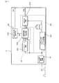
- FIG. 1 is a circuit configuration diagram of an ignition control device to which an internal combustion engine ignition device is applied according to the first embodiment.
- FIG. 2 is a waveform diagram of a main ignition signal in the first embodiment.
- FIG. 3 is a circuit configuration diagram of a signal generation circuit unit included in the ignition device according to the first embodiment.
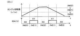
- FIG. 4 is a diagram illustrating a relationship between the rotation speed region determined by the IGA generation unit of the ignition device and the target secondary current command signal IGA in the first embodiment.
- FIG. 1 is a circuit configuration diagram of an ignition control device to which an internal combustion engine ignition device is applied according to the first embodiment.
- FIG. 2 is a waveform diagram of a main ignition signal in the first embodiment.
- FIG. 3 is a circuit configuration diagram of a signal generation circuit unit included in the ignition device according to the first embodiment.
- FIG. 4 is a diagram illustrating a relationship between the rotation speed region determined by the IGA generation unit of the ignition device and the target secondary current command signal IGA in the first embodiment.
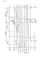
- FIG. 5 is a time chart showing the transition of the main ignition signal and various signals generated in the signal generation circuit unit, the main ignition operation, and the energy input operation in the first embodiment.
- FIG. 6 is a flowchart of main ignition operation executed by the ignition device and rotation speed region determination processing by the signal generation circuit unit in the first embodiment.
- FIG. 7 is a circuit configuration diagram of a signal generation circuit unit included in the ignition device according to the second embodiment.
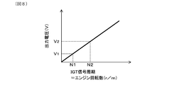
- FIG. 8 is a diagram showing the relationship between the output voltage of the F / V converter circuit and the engine speed in the second embodiment.
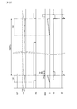
- FIG. 9 is a time chart showing the transition of the main ignition signal and various signals generated in the signal generation circuit unit, the main ignition operation, and the energy input operation in the second embodiment.
- FIG. 10 is a circuit configuration diagram of a signal generation circuit unit included in the ignition device according to the third embodiment.
- FIG. 11 is a time chart showing the transition of the main ignition signal and various signals generated in the signal generation circuit unit, the main ignition operation, and the energy input operation in Embodiment 4.
- FIG. 12 is a circuit configuration diagram of an ignition control device for an internal combustion engine in the fifth embodiment.
- FIG. 13 is a circuit configuration diagram of an ignition control device for an internal combustion engine in the sixth embodiment.
- an ignition device 10 is applied to, for example, an in-vehicle spark ignition engine, and constitutes an ignition control device 1 that controls ignition of a spark plug P provided for each cylinder.
- the ignition control device 1 includes an ignition coil 2, a main ignition circuit unit 3, an energy input circuit unit 4, and a signal generation circuit unit 5, and an engine electronic that gives an ignition command to the ignition device 10.
- a control device hereinafter referred to as an engine ECU; abbreviated as Electronic Control Unit 100 is provided.
- the ignition coil 2 generates discharge energy in the secondary coil 22 connected to the spark plug P by increasing / decreasing the primary current I1 flowing through the primary coil 21.
- the main ignition circuit unit 3 controls the energization of the primary coil 21 of the ignition coil 2 to perform a main ignition operation that causes spark discharge in the spark plug P.
- the energy input circuit unit 4 performs an energy input operation in which a current of the same polarity is superimposed on the secondary current I2 flowing through the secondary coil 22 by the main ignition operation.
- the primary coil 21 includes, for example, a main primary coil 21a and a sub primary coil 21b, and the energy input circuit unit 4 controls the energy input operation by controlling energization to the sub primary coil 21b.
- the engine ECU 100 generates and transmits a pulsed main ignition signal IGT for each combustion cycle. Based on the waveform information of the main ignition signal IGT that controls the main ignition operation, the signal generation circuit unit 5 controls the energy input signal IGW that controls the energy input operation and the target secondary current that instructs the target secondary current value I2tgt. At least one of the command signals IGA can be generated. Preferably, both the energy input signal IGW and the target secondary current command signal IGA are generated.
- information for example, signal cycle time
- T can be used to determine the engine operating range (for example, the engine speed range). Then, it is determined whether or not the energy input operation can be performed based on the determination result.
- the energy input signal IGW and the target secondary current command signal IGA or Both can be generated to control the energy input operation.
- the information included in the pulse signal waveform includes the rising or falling position, pulse width, signal period, etc. of the pulse signal, and the positional relationship of the rising or falling edges of two or more pulse signals. Any information known from one or a combination is used.
- the engine speed region can be determined as will be described later by adopting the measurement result of the signal cycle time T represented by the falling edge interval corresponding to the ignition position of the two main ignition signals IGT. it can.
- the ignition device 10 operates the main ignition circuit unit 3 based on the main ignition signal IGT to perform the main ignition operation. Further, after the main ignition, based on the energy input signal IGW, the energy input circuit unit 4 is operated to perform the energy input operation, and the spark discharge is continued. The energy input in this continuous discharge is instructed by the target secondary current command signal IGA.
- the ignition control device 1 further includes a feedback control unit 6 that feedback-controls the secondary current I2, and the secondary current I2 that flows through the secondary coil 22 of the ignition coil 2 based on the target secondary current command signal IGA. Is feedback-controlled so that becomes the target secondary current value I2tgt.
- An engine to which the ignition device 10 of the present embodiment is applied is, for example, a four-cylinder engine, and a spark plug P (for example, shown as P # 1 to P # 4 in FIG. 1) corresponding to each cylinder.
- An ignition device 10 is provided for each of the spark plugs P.
- the main ignition signal IGT is transmitted to each ignition device 10 from the engine ECU 100 to each cylinder ignition device 10 in each phase according to the ignition position of each cylinder.
- the spark plug P has a known configuration including a center electrode P1 and a ground electrode P2 facing each other, and a space formed between the tips of both electrodes is a spark gap G.
- the spark plug P is supplied with discharge energy generated in the ignition coil 2 based on the main ignition signal IGT, and spark discharge occurs in the spark gap G, so that the air-fuel mixture in the engine combustion chamber (not shown) can be ignited. It becomes.
- Energization of the ignition coil 2 is controlled based on the energy input signal IGW and the target secondary current command signal IGA in addition to the main ignition signal IGT.
- a primary primary coil 21a or sub-primary coil 21b serving as a primary coil 21 and a secondary coil 22 are magnetically coupled to each other to form a known step-up transformer.
- One end of the secondary coil 22 is connected to the center electrode P1 of the spark plug P, and the other end is grounded via the first diode 221 and the secondary current detection resistor R1.
- the first diode 221 is arranged such that the anode terminal is connected to the secondary coil 22 and the cathode terminal is connected to the secondary current detection resistor R1, and the direction of the secondary current I2 flowing through the secondary coil 22 is regulated.
- the secondary current detection resistor R1 constitutes a feedback control unit 6 together with a secondary current feedback circuit (for example, shown as I2F / B in FIG. 1) 61 whose details will be described later.
- the main primary coil 21a and the sub primary coil 21b are connected in series, and are connected in parallel to a DC power source B such as a vehicle battery. Specifically, an intermediate tap 23 is provided between one end of the main primary coil 21a and one end of the sub primary coil 21b, and a power line L1 reaching the DC power source B is connected to the intermediate tap 23. .
- the other end of the main primary coil 21a is grounded via a switching element for main ignition (hereinafter abbreviated as a main ignition switch) SW1, and the other end of the sub-primary coil 21b is connected to a switching element for continuing discharge (hereinafter referred to as a main ignition switch). This is grounded via SW2.
- the main ignition switch SW1 or the discharge continuation switch SW2 when the main ignition switch SW1 or the discharge continuation switch SW2 is turned on, the battery voltage can be applied to the main primary coil 21a or the sub primary coil 21b.
- the main ignition switch SW1 constitutes the main ignition circuit unit 3
- the discharge continuation switch SW2 constitutes the energy input circuit unit 4.
- the ignition coil 2 is integrally configured by winding the primary coil 21 and the secondary coil 22 around, for example, a primary coil bobbin and a secondary coil bobbin disposed around the core 24. At this time, a predetermined high voltage corresponding to the turn ratio is increased by sufficiently increasing the turn ratio, which is the ratio of the turn of the primary primary coil 21a or the sub primary coil 21b, which is the primary coil 21, and the turn of the secondary coil 22. Can be generated in the secondary coil 22.
- the main primary coil 21a and the sub primary coil 21b are wound so that the direction of the magnetic flux generated upon energization from the DC power source B is opposite, and the number of turns of the sub primary coil 21b is larger than the number of turns of the main primary coil 21a. Set less.
- the main ignition circuit unit 3 includes a main ignition switch SW1 and a switch driving circuit for main ignition operation (hereinafter abbreviated as a main ignition driving circuit) 31 for driving the main ignition switch SW1 on and off.
- the main ignition switch SW1 is a voltage-driven switching element, for example, an IGBT (that is, an insulated gate bipolar transistor), and the collector potential is controlled by controlling the gate potential according to the drive signal input to the gate terminal. Between the emitter terminal and the emitter terminal. The collector terminal of the main ignition switch SW1 is connected to the other end of the main primary coil 21a, and the emitter terminal is grounded.
- the main ignition drive circuit 31 generates a drive signal in response to the main ignition signal IGT and drives the main ignition switch SW1 on or off. Specifically (for example, refer to FIG. 5), when the main ignition switch SW1 is turned on at the rise of the main ignition signal IGT, energization of the main primary coil 21a is started, and the primary current I1 flows. Next, when the main ignition switch SW1 is turned off at the fall of the main ignition signal IGT, the energization to the main primary coil 21a is cut off, and a high voltage is generated in the secondary coil 22 by the mutual induction action. This high voltage is applied to the spark gap G of the spark plug P, spark discharge is generated, and the secondary current I2 flows.
- the energy input circuit unit 4 includes a discharge continuation switch SW2 and a sub primary coil control circuit 41 that outputs a drive signal for switching the discharge continuation switch SW2 to control energization of the sub primary coil 21b. Composed.
- a switching element hereinafter abbreviated as a reflux switch
- SW3 that opens and closes the return path L11 connected to the sub primary coil 21b is provided, and is turned on and off by a drive signal from the sub primary coil control circuit 41. Yes.
- the discharge continuation switch SW2 and the reflux switch SW3 are voltage-driven switching elements, for example, MOSFETs (that is, field effect transistors), and the gate potential is controlled according to the drive signal input to the gate terminal.
- MOSFETs that is, field effect transistors
- the drain terminal and the source terminal are electrically connected or disconnected.
- the drain terminal of the discharge continuation switch SW2 is connected to the other end of the sub primary coil 21b, and the source terminal is grounded.
- the reflux path L11 is provided between the other end of the sub primary coil 21b (that is, the side opposite to the main primary coil 21a) and the power supply line L1.
- the drain terminal of the reflux switch SW3 is connected to the connection point between the other end of the sub primary coil 21b and the discharge continuation switch SW2, and the source terminal is connected to the power supply line L1 via the second diode 11.
- the power supply line L1 is provided with a third diode 12 between the connection point with the reflux path L11 and the DC power supply B.
- the second diode 11 has a forward direction toward the power supply line L1
- the third diode 12 has a forward direction toward the primary coil 21.
- the recirculation switch SW3 is turned on, whereby the other end of the sub primary coil 21b and the power supply line L1 are connected via the recirculation path L11. Accordingly, a return current flows when the energization to the sub-primary coil 21b is cut off, and the current of the sub-primary coil 21b changes gently, so that a rapid decrease in the secondary current I2 can be suppressed.
- the main ignition drive circuit 31 receives the main ignition signal IGT output from the signal generation circuit unit 5 via the output signal line L2. Further, the energy input signal IGW and the target secondary current command signal IGA output from the signal generation circuit unit 5 are input to the sub primary coil control circuit 41 via the output signal lines L3 to L4. Further, the secondary primary coil control circuit 41 receives the feedback signal SFB from the secondary current feedback circuit 61 of the feedback control unit 6, and further receives the battery voltage signal SB from the power supply line L1 to perform the energy input operation. Used for necessity determination.
- the output signal line L4 of the target secondary current command signal IGA is connected to the input terminal of the secondary current feedback circuit 61.
- the secondary current feedback circuit 61 receives the target secondary current command signal IGA, compares it with the detected value of the secondary current I2 based on the secondary current detection resistor R1, and outputs it to the sub primary coil control circuit 41. Specifically, based on the target secondary current value I2tgt instructed by the target secondary current command signal IGA, the detected secondary current I2 is determined as a threshold value and fed back to the open / close drive of the discharge continuation switch SW2.
- the signal SFB is output.
- the sub-primary coil control circuit 41 determines whether or not the energy input operation can be performed based on a combination of signals input from these units. For example, based on the energy input signal IGW and other energy input conditions (for example, implementation of feedback control based on the feedback signal SFB, battery voltage signal SB, etc.), a drive signal is generated at a predetermined timing, and the discharge continuation switch SW2 The reflux switch SW3 is driven on or off. Further, a delay time Td and the like for starting the energy input operation at a predetermined timing after the main ignition operation are set.
- the energy input signal IGW rises to instruct the energy input period, and after a predetermined delay time Td, the discharge continuation switch SW2 is driven. A signal is output and an energy input operation is performed. Further, while the energy input operation is performed, feedback control for maintaining the target secondary current value I2tgt is performed based on the feedback signal SFB.
- the secondary current feedback circuit 61 includes a comparison circuit for comparing the detected secondary current I2 with a threshold value, and switching means for switching the threshold value.
- the comparison circuit uses the target secondary current command signal IGA as the reference voltage of the comparator, and either the upper limit threshold value or the lower limit threshold value from the reference voltage is appropriately switched and input, and the voltage is converted by the secondary current detection resistor R1.
- the comparison result with the detected signal is output as the feedback signal SFB.
- the upper limit threshold and the lower limit threshold are set, for example, with the target secondary current value I2tgt as the center, and the upper limit threshold turns off the discharge continuation switch SW2 when the secondary current I2 is increased by driving the discharge continuation switch SW2 on.
- the lower limit threshold is selected.
- the upper limit threshold and the lower limit threshold are switched accordingly.
- the sub-primary coil control circuit 41 is provided with an AND circuit of an energy input signal IGW and a feedback signal SFB which is a secondary current comparison result, for example, to drive the discharge continuation switch SW2.
- the feedback signal SFB is input.
- the feedback signal SFB is, for example, L level when the detection signal is larger than the upper limit threshold, and H level when the detection signal is smaller than the lower limit threshold. That is, when the energy input signal IGW is output, the discharge continuation switch SW2 is turned on when the secondary current I2 falls below the lower threshold value, and turned off when the secondary current I2 exceeds the upper threshold value. Is made.
- the signal generation circuit unit 5 includes an IGT waveform shaping circuit 51, a rotation speed region determination unit 52 that determines an engine rotation speed region (that is, an operation region determination unit that determines an operation region of the internal combustion engine), an energy It has an IGW generating unit 53 that generates a closing signal IGW and an IGA generating unit 54 that generates a target secondary current command signal IGA.
- the main ignition signal IGT input to the signal generation circuit unit 5 is first subjected to filtering processing in the IGT waveform shaping circuit 51, and as a main ignition signal IGT having a rectangular waveform from which noise has been removed, a rotation speed region determination unit 52 and an IGW generation unit 53, respectively.
- a rotation speed region determination unit 52 in order to determine whether or not the energy input operation can be performed from the engine operation region, a rotation speed region determination unit 52 is provided, and the current engine rotation speed region is determined based on the main ignition signal IGT after waveform shaping. To do.
- the IGW generation unit 53 Based on the output from the rotation speed region determination unit 52, the IGW generation unit 53 outputs the energy input signal IGW when the current engine speed region is a region where the energy input operation is performed.
- the IGA generation unit 54 generates a target secondary current command signal IGA based on the output from the rotation speed region determination unit 52.
- the IGW generation unit 53 includes a Tw one-shot pulse generation circuit 531 with a Td delay and a first AND gate 532 serving as an IGW output circuit 530.
- the input terminal of the Tw one-shot pulse generation circuit 531 with Td delay is connected to the output terminal of the IGT waveform shaping circuit 51.
- a Tw one-shot pulse generation circuit 531 with a Td delay is triggered by a falling signal of the main ignition signal IGT as a trigger and is delayed by a delay time Td and has a constant pulse width time Tw (hereinafter abbreviated as Tw pulse). And output only once.
- the pulse width time Tw is set in advance to a certain time that can be used as the energy input signal IGW (that is, the energy input period).
- the delay time Td is set so that the discharge will start at the spark gap G of the spark plug P from the fall of the IGT signal, and the current due to energy input is superimposed on the secondary current I2. Has been.
- the first AND gate 532 generates the energy input signal IGW based on the logical product of the output from the rotation speed region determination unit 52 and the output from the Tw one-shot pulse generation circuit 531 with Td delay.
- the rotation speed region determination unit 52 includes a T1 one-shot pulse generation circuit 521 and a T2 one-shot pulse generation circuit 522, a first D flip-flop 523 and a second D flip-flop 524, a first inverter 525, and a second inverter 526.
- the output terminal of the IGT waveform shaping circuit 51 is connected in parallel to the input terminals of the T1 one-shot pulse generation circuit 521 and the T2 one-shot pulse generation circuit 522 via the first inverter 525 and the second inverter 526.
- the output terminal of the IGT waveform shaping circuit 51 is connected in parallel to the clock terminals (hereinafter referred to as C terminals) of the first D flip-flop 523 and the second D flip-flop 524.
- the first inverter 525 and the second inverter 526 are two inverter gates connected in series, and delay the main ignition signal IGT after waveform shaping, so that the T1 one-shot pulse generation circuit 521 and the T2 one-shot pulse generation circuit 522 Enter each.
- the output terminal of the T1 one-shot pulse generation circuit 521 is connected to the data terminal (hereinafter referred to as D terminal) of the first D flip-flop 523, and the output terminal of the T2 one-shot pulse generation circuit 522 is connected to the second D flip-flop. It is connected to the D terminal of 524.
- the output signals of the first D flip-flop 523 and the second D flip-flop 524 are delayed from the input of the main ignition signal IGT to the C terminal by the propagation delay of the first inverter 525 and the second inverter 526, and the D terminal Is input.
- the output levels of the first D flip-flop 523 and the second D flip-flop 524 are latched by the output levels of the T1 one-shot pulse generation circuit 521 and the T2 one-shot pulse generation circuit 522 activated at the previous fall of the IGT signal.
- the T1 one-shot pulse generation circuit 521 generates a one-shot pulse signal (hereinafter abbreviated as T1 pulse) having a constant pulse width time T1 triggered by the falling signal of the main ignition signal IGT and outputs it only once. To do.
- the T2 one-shot pulse generation circuit 522 generates a one-shot pulse signal (hereinafter, abbreviated as T2 pulse) having a constant pulse width time T2 using a falling signal of the main ignition signal IGT as a trigger. Output only once.
- the pulse width times T1 and T2 are constant times serving as threshold values for determining whether or not the energy input operation can be performed, and are set to be the signal cycle time T of the fall of the main ignition signal IGT corresponding to a predetermined engine speed. Is set in advance.
- the pulse width time T1 is longer than the pulse width time T2 (that is, T1> T2).
- the signal cycle time T becomes longer as the engine speed is lower, and the signal cycle time T is shorter as the engine speed is higher. Therefore, it corresponds to the upper and lower limits of the engine speed region where the energy input operation is performed.
- the first AND gate 532 is connected to the output terminal (hereinafter referred to as Q terminal) of the first D flip-flop 523 and the inverted output terminal (hereinafter referred to as Q bar terminal) of the second D flip-flop 524. .
- Q terminal the output terminal of the first D flip-flop 523
- Q bar terminal the inverted output terminal of the second D flip-flop 524.
- the output of the Tw one-shot pulse generation circuit 531 with a Td delay and the Q terminal outputs of the first D flip-flop 523 and the second D flip-flop 524 are set so that the initial value when the power is turned on is L level.
- these outputs generate a short clear pulse from the end edge of the Tw one-shot pulse with Td delay or the end edge of the T1 one-shot pulse so as to be surely at the L level at the end point of the energy input signal IGW. It may be set.
- the operation for the next main ignition signal IGT can be performed correctly, and it is initialized to the L level even when the engine is stopped, and the restart operation can be performed correctly.
- the IGA generator 54 includes a target secondary current setting circuit 541 that generates a target secondary current command signal IGA, and a first voltage dividing circuit 542.
- the target secondary current setting circuit 541 includes a first multiplexer M1, and the Q terminal of the first D flip-flop 523 and the Q terminal of the second D flip-flop 524 are connected to the A terminal and the B terminal of the first multiplexer M1, respectively. Is done.
- the first multiplexer M1 selects one of the four input terminals X0 to X3 based on the logic (A: B) of the input signals of the A terminal and the B terminal, and the input voltage signal (X0 to X3). Is output from the X terminal as the target secondary current command signal IGA.
- the first voltage dividing circuit 542 divides the voltage of the first voltage source 543 by the two resistors R2 and R3, generates the reference voltage signal X1, and outputs it to the X1 terminal of the first multiplexer M1.
- the other X0 terminals, X2 to X3 terminals are connected between the resistor R3 and the ground terminal.
- a target secondary current value I2tgt corresponding to the reference voltage signal X1 is set, and an energy input operation is performed.
- the main ignition signals IGT (1) to (3) show the operation waveforms in the rotation speed ranges NE0 to NE2, respectively.
- the main ignition signals IGT (1) to (3) are output once in one combustion cycle (for example, 720 ° CA), energization is started in the main primary coil 21a at the rising edge, and the main primary coil 21a is output at the falling edge.
- the main ignition operation is performed by cutting off the current.
- steps S1 to S4 correspond to the main ignition operation.
- step S1 it is determined whether or not the main ignition signal IGT is at the H level (that is, the IGT signal Hi?). If an affirmative determination is made, the process proceeds to step S2 and the main ignition circuit unit. 3 turns on the main ignition switch SW1. Thereafter, the process returns to the start of this process. Thereby, energization to the main primary coil 21a of the ignition coil 2 is started, and energization is continued while the main ignition signal IGT is at the H level, and the primary current I1 gradually increases (for example, I1 in FIG. 5). reference).
- step S1 determines whether or not the fall of the main ignition signal IGT is detected (that is, the IGT signal falls?), And the determination in step S3 is affirmative. In this case, the process proceeds to step S4, the main ignition switch SW1 is turned off, and the main ignition operation is started. That is, the energization of the ignition coil 2 to the main primary coil 21a is cut off, so that a high secondary voltage V2 is generated in the secondary coil 22, a spark discharge is generated in the spark plug P, and the secondary current I2 is Flows (see, for example, V2 and I2 in FIG. 5). If step S3 is negative, the process returns to the start of this process.
- the energy input operation is performed by the energy input signal IGW. Execution of the energy input operation is instructed based on the previous main ignition signal IGT. Therefore, prior to the current main ignition operation, the previous main ignition signal IGT is input to the rotation speed region determination unit 52 and the IGW generation unit 53 of the signal generation circuit unit 5, and the T1 pulse and the T2 pulse are T1 one. Output from the shot pulse generation circuit 521 and the T2 one-shot pulse generation circuit 522, respectively.
- the main ignition signal IGT (1) in FIG. 5 corresponds to the low speed region NE0, and the signal cycle time T of the previous main ignition signal IGT becomes longer, so the signal corresponding to one combustion cycle.
- the pulse width times T1 and T2 of the constant T1 pulse and T2 pulse are shorter than the cycle time T. Therefore, the T1 pulse and the T2 pulse fall before the current main ignition signal IGT (1) falls, and the S terminals of the first D flip-flop 523 and the second D flip-flop 524 become L level.
- the predetermined output start time delayed from the fall of the main ignition signal IGT (1) is the D terminal level as a result of starting with the previous main ignition signal IGT signal of the first D flip-flop 523 and the second D flip-flop 524,
- the time is set so as to be surely latched at the Q terminal and the Q bar terminal and have a width that can instruct the energy input period, for example, a delay time of 10 uSec to 100 uSec, and the Tw pulse is output,
- the input to the 1 AND gate 532 becomes H level.
- the output of the Q bar terminal of the second D flip-flop 524, which is input to the first AND gate 532 is also at the H level.
- the output of the Q terminal of the first D flip-flop 523 is at the L level, energy is input.
- the signal IGW is not output.
- the outputs of the A and B terminals of the first multiplexer M1 to which the Q terminals of the first and second D flip-flops 523 and 524 are connected (that is, in FIG. 5).
- M1-A and M1-B) are also at the L level. If the previous time is also in the rotation speed region NE0, the L level is continuously output.
- the main ignition signal IGT (2) corresponds to the rotation speed region NE1 on the higher rotation side than the rotation speed region NE0, and the signal cycle time T becomes shorter. Therefore, only the T2 pulse falls before the current main ignition signal IGT (2) falls, and the T1 pulse remains at the H level.
- the main ignition signal IGT (2) falls, the output of the Q terminal of the first D flip-flop 523 becomes H level.
- the output of the Q terminal of the second D flip-flop 524 becomes L level, and the output of the Q bar terminal becomes H level.
- the first AND gate 532 is opened and the energy input signal IGW is output.
- the outputs of the A and B terminals of the first multiplexer M1 to which the Q terminals of the first and second D flip-flops 523 and 524 are connected (that is, in FIG. 5).
- M1-A and M1-B) are H level and L level, respectively.
- the target secondary current command signal IGA corresponding to the target secondary current value I2tgt is output from the X terminal of the first multiplexer M1.
- the energy input circuit unit 4 turns on the discharge continuation switch SW2 to perform the energy input operation. That is, the secondary primary coil 21b is energized, the secondary current I2 is superimposed, and the spark discharge is maintained. At this time, the superposed discharge energy is instructed by the target secondary current command signal IGA and compared with the measured value of the secondary current. Then, the drive signal of the discharge continuation switch SW2 is feedback controlled so that the secondary current I2 becomes the target secondary current value I2tgt by the feedback signal SFB that is a comparison result from the feedback control unit 6.
- the main ignition signal IGT (3) corresponds to the rotation speed region NE2 on the higher rotation side than the rotation speed region NE1, and the signal cycle time T becomes shorter. For this reason, the T1 pulse and the T2 pulse remain at the H level at the falling edge of the current main ignition signal IGT (3).
- the main ignition signal IGT (3) falls, the outputs of the Q terminals of the first D flip-flop 523 and the second D flip-flop 524 become H level.
- the output of the Q bar terminal of the second D flip-flop 524 becomes L level, even if the Tw pulse output from the Tw one-shot pulse generation circuit 531 with Td delay becomes H level, the first AND gate 532 Does not output the energy input signal IGW.
- the outputs of the A and B terminals of the first multiplexer M1 to which the Q terminals of the first and second D flip-flops 523 and 524 are connected (that is, in FIG. 5).
- M1-A and M1-B) are also at the H level.
- the target secondary current command signal IGA which is an output from the terminal, becomes zero level, and the target secondary current value I2tgt becomes 0 mA.
- Steps S5 to S10 in FIG. 6 correspond to the determination operation of the rotation speed region.
- step S10 based on the current fall of the main ignition signal IGT, the T1 pulse and the T2 pulse are output at predetermined pulse width times T1 and T2, respectively (that is, T1, T2 one-shot pulse output). These T1 pulse and T2 pulse are used for determination of the rotation speed region in the next ignition control based on the main ignition signal IGT.
- step sequence from step S5 to step S10 is performed through the signal delay circuit of the first inverter 525 and the second inverter 526 through the C terminal input of the first D flip-flop 523 and the second D flip-flop 524 in FIG.
- This corresponds to a sequence for starting a shot pulse and a T2 one-shot pulse.
- the determination of the rotation speed region does not have to be performed for each combustion cycle, and may be performed using, for example, a signal period time T between a plurality of combustion cycles.
- the switching operation may be performed based on a plurality of determination results, and the determination value may be provided with hysteresis. Thereby, chattering etc. of the switching operation can be suppressed and the switching operation can be stabilized.
- a rotation region including an operation region that is difficult to ignite can be selected, and the energy input operation can be efficiently performed only by the main ignition signal IGT.
- IGT main ignition signal
- the energy input signal IGW and the target secondary current command signal IGA can be generated only from the main ignition signal IGT transmitted from the engine ECU 100 to the ignition device 10. Therefore, there is no need to change the transmission signal from engine ECU 100, and there is only one signal line for transmitting main ignition signal IGT. Therefore, signal terminals provided in each device and signal lines for connecting between the devices. Etc. can be reduced. Further, since the ignition signal IGT being used can be used as it is, the ignition device 10 capable of energy input can be retrofitted without changing the specifications on the engine ECU 100 side. Therefore, the energy input operation following the main ignition operation can be optimally controlled, and a small and high performance internal combustion engine ignition device 10 can be realized.
- the output of the Q bar terminal of the second D flip-flop 524 to the first AND gate 532 is abolished, and the output of the target secondary current command signal IGA is set to zero level.
- the energy input operation may not be performed.
- the circuit configuration can be simplified to further simplify the device configuration.
- the output of the Tw one-shot pulse generation circuit 531 with a Td delay and the Q terminal outputs of the first D flip-flop 523 and the second D flip-flop 524 are preset and started at the H level when the power is turned on or the engine is stopped. It is good also as a setting. With this configuration, the energy input operation can be performed without delay even when the engine is started.
- FIGS. 1 and 2 A second embodiment of the ignition control device for an internal combustion engine will be described with reference to FIGS.
- the configuration of the rotation speed region determination unit 52 for determining the engine operation region is different. Yes.
- the basic configuration of the ignition control device 1 including the ignition device 10 and the engine ECU 100 is the same as that of the first embodiment, and the differences will be mainly described below.
- the same reference numerals as those used in the above-described embodiments represent the same components as those in the above-described embodiments unless otherwise indicated.
- the signal generation circuit unit 5 includes an IGT waveform shaping circuit 51, a rotation speed region determination unit 52 that determines an engine rotation speed region, an IGW generation unit 53 that generates an energy input signal IGW, and a target secondary current.
- An IGA generator 54 that generates a command signal IGA.
- the main ignition signal IGT input to the signal generation circuit unit 5 is first subjected to filtering processing in the IGT waveform shaping circuit 51, and as a main ignition signal IGT having a rectangular waveform from which noise has been removed, the rotational speed region determination 52 and the IGW generation unit 53 are performed. Are output respectively.
- the configuration of the IGW generation unit 53 is the same as that of the first embodiment, and the description is omitted or simplified.
- the rotation speed area determination unit 52 includes an F / V converter circuit 551 and a rotation speed area determination circuit 552.
- the main ignition signal IGT after waveform shaping is input to the F / V converter circuit 551.
- the F / V converter circuit 551 for example, generates a falling signal from the input pulse-shaped main ignition signal IGT by a differentiation circuit, calculates the frequency of each cycle of this signal, and converts it into a voltage signal VO. Output.
- the output voltage characteristic of the F / V converter circuit 551 is proportional to the engine speed correlated with the signal cycle of the main ignition signal IGT. Therefore, using this relationship, it can be detected from the output voltage of the F / V converter circuit 551 that a predetermined engine speed has been reached.
- the input signal cycle of the main ignition signal IGT to the F / V converter circuit 551 is preferably the cycle between the falling signals.
- two engine rotation speeds for example, N1, N2; N1 ⁇ N2
- two reference voltages corresponding thereto For example, V 1 , V 2 ; V 1 ⁇ V 2
- V 1 , V 2 V 1 ⁇ V 2
- the rotation speed region determination circuit 552 determines the rotation speed region by comparing the voltage signal VO output from the F / V converter circuit 551 with the reference voltages V 1 and V 2 . Then, when the voltage signal VO is in a range defined by the reference voltages V 1 and V 2 , it is determined that the engine speed is in a predetermined speed range, and the permission signal EN for permitting execution of the energy input operation. Is generated and output.
- the permission signal EN serves as a command signal for permitting / prohibiting output of the energy input signal IGW, and serves as a command signal for permitting / prohibiting output of the target secondary current command signal IGA.
- the IGW generation unit 53 receives the Tw pulse from the Tw one-shot pulse generation circuit 531 with Td delay. Then, this is output as an energy input signal IGW.
- the IGA generation unit 54 sets the target secondary current corresponding to the target secondary current value I2tgt set in advance corresponding to a predetermined rotation speed region. The current command signal IGA is output.
- the main ignition signal IGT is output every combustion cycle (for example, 720 ° CA), and the rotational speed region determination using the F / V converter circuit 551 is performed at the falling position. .
- the voltage signal VO output from the F / V converter circuit 551 is compared with the reference voltage, and VO is between the reference voltages V 1 and V 2 .
- the enabling signal EN becomes H level.
- Voltage signal VO is the operation of the F / V converter circuit 551, then gradually decreases and falls below the reference voltage V 1, enable signal EN is at the L level.
- the permission signal EN becomes H level, and the energy input signal IGW of the pulse width time Tw is output delayed by a predetermined delay time Td, After the delay time Td has elapsed, the energy input operation is performed. Further, the secondary current I2 is feedback-controlled based on the target secondary current command signal IGA output from the target secondary current setting circuit 541.
- the determination of the rotation speed region using the output from the F / V converter circuit 551 may be performed every time the main ignition signal IGT falls or may be determined once every plural times. Or you may change so that the determination result in multiple times may be averaged, and it can set arbitrarily. Further, the determination result with respect to the reference voltage may be implemented at the falling position of the main ignition signal IGT, and the result may be controlled by holding the result for a predetermined period, for example, four combustion cycles, to stabilize the energy input operation.
- the energy input signal IGW and the target secondary current command signal IGA can be generated only from the main ignition signal IGT.
- the energy input operation following the main ignition operation can be optimally controlled, and a small and high-performance internal combustion engine ignition device 10 can be realized.
- the ignition signal IGT being used can be used as it is, the ignition device 10 capable of energy input can be retrofitted without changing the specifications on the engine ECU 100 side.
- FIGS. 3 A third embodiment of the ignition control device for an internal combustion engine will be described with reference to FIGS.
- the rotation speed region determination unit 52 of the signal generation circuit unit 5 sets three rotation speed regions and performs the energy input operation in one of the rotation speed regions.
- the energy input operation may be performed in the above rotation speed range.
- the energy input period indicated by the energy input signal IGW and the setting of the target secondary current value I2tgt indicated by the target secondary current command signal IGA may be changed.
- the energy input signal IGW and the target secondary current command signal IGA are switched between two rotation speed ranges.
- the basic configuration of the ignition control device 1 including the ignition device 10 is the same as that of the first embodiment, and the following description will focus on differences.
- the signal generation circuit unit 5 includes an IGT waveform shaping circuit 51, a rotation speed region determination unit 52, an IGW generation unit 53 that generates an energy input signal IGW, and an IGA that generates a target secondary current command signal IGA. And a generation unit 54.
- the main ignition signal IGT input to the signal generation circuit unit 5 is first subjected to filtering processing in the IGT waveform shaping circuit 51, and as a main ignition signal IGT having a rectangular waveform from which noise has been removed, a rotation speed region determination unit 52 and an IGW generation unit 53, respectively.
- the IGW generation unit 53 includes a Tw1 one-shot pulse generation circuit 534 with a Td delay, a Tw2 one-shot pulse generation circuit 535 with a Td delay, a second multiplexer M2, and a first AND gate 532 serving as an IGW output circuit 530.
- the Tw1 and Tw2 one-shot pulse generation circuits 534 and 535 are triggered by the falling signal of the main ignition signal IGT from the IGT waveform shaping circuit 51 as a trigger, respectively, and are delayed by a predetermined delay time Td to be a constant pulse width time Tw1,
- a one-shot pulse signal having Tw2 (hereinafter abbreviated as Tw1 pulse and Tw2 pulse) is generated and output.
- the pulse width times Tw1 and Tw2 are constant times that can be used as the energy input signal IGW for instructing the energy input period, and are set in advance to different times (for example, Tw1 ⁇ Tw2).
- the second multiplexer M2 has the same configuration as the first multiplexer M1 of the IGA generation unit 54 to be described later, and based on the logic (A: B: C) of the input signals at the A to C terminals, Select one of the two input terminals. Input voltage signals (X0 to X7) of the selected input terminal are input to the first AND gate 532 from the X terminal. The first AND gate 532 generates the energy input signal IGW based on the logical product of the output from the rotation speed region determination unit 52 and the output from the second multiplexer M2.
- the relationship between (A: B: C) and (X0 to X7) is as follows.
- the rotation speed region determination unit 52 includes a T3 one-shot pulse generation circuit 527 in addition to the T1 one-shot pulse generation circuit 521 and the T2 one-shot pulse generation circuit 522.
- a third D flip-flop 528 is provided in addition to the first D flip-flop 523 and the second D flip-flop 524.
- the output terminal of the IGT waveform shaping circuit 51 is connected in parallel to the input terminals of the T1 to T3 one-shot pulse generation circuits 521, 522, and 527 via the first inverter 525 and the second inverter 526, and
- the first to third D flip-flops 523, 524, and 528 are connected in parallel to the C terminals.
- the T3 one-shot pulse generation circuit 527 uses the falling signal of the main ignition signal IGT as a trigger to trigger a one-shot pulse signal (hereinafter, referred to as a one-shot pulse signal having a constant pulse width time T3). (Abbreviated as T3 pulse) and output only once.
- the output terminals of the T1 to T3 one-shot pulse generation circuits 521, 522, and 527 are connected to the D terminals of the first to third D flip-flops 523, 524, and 528, respectively, and receive T1 to T3 pulses.
- the pulse width times T1 to T3 are preset to different times so as to be the signal cycle time T of the fall of the main ignition signal IGT corresponding to a predetermined engine speed (for example, T1> T2> T3). ).
- a predetermined engine speed for example, T1> T2> T3.
- two predetermined rotation speed regions (pulse width times T1, T2) are set. It is possible to determine whether or not the energy input operation can be performed by determining whether or not the energy input operation is in the rotation speed region defined by (3) or the rotation speed region defined by the pulse width times T2 and T3.
- the first to third D flip-flops 523, 524, and 528 use, as the logic level of the D terminal, the signal output at the previous fall of the main ignition signal IGT every time the main ignition signal IGT input to the C terminal falls. Latch and output to Q terminal.
- the Q terminals of the first to third D flip-flops 523, 524, and 528 are connected to the A to C terminals of the second multiplexer M1, respectively.
- the output terminal of the Tw1 one-shot pulse generation circuit 534 with Td delay is connected to the X1 terminal of the second multiplexer M1, and the output terminal of the Tw2 one-shot pulse generation circuit 535 with Td delay is connected to the X3 terminal.
- the X0 terminal and the X2 terminal are connected to the ground terminal.
- the first AND gate 532 is connected to the Q terminal of the first D flip-flop 523 and the Q bar terminal of the third D flip-flop 527.
- the level of the Q terminal is inverted and output to the Q bar terminal of the third D flip-flop 527. Accordingly, the signal cycle time T of the main ignition signal IGT is in the range of the pulse width times T1 to T3, and the X terminal of the second multiplexer M1 is connected to the X1 terminal or the X3 terminal, so that the Tw1 pulse or Tw2 When the pulse is output, the output from the first AND gate 532 becomes H level. That is, the selected Tw1 pulse or Tw2 pulse is output as the energy input signal IGW.
- Table 2 below shows the relationship between the combination of (A: B: C) corresponding to four rotation speed regions including two predetermined rotation speed regions and whether or not the energy input operation can be performed.
- the Q terminals of the first to third D flip-flops 523, 524, and 528 are connected to the A to C terminals of the first multiplexer M1, respectively.
- the first multiplexer M1 selects one of the four input terminals X0 to X3 based on the logic (A: B: C) of the input signals of the A to C terminals, The input voltage signals (X0 to X3) are output to the X terminal.
- the target secondary current command signal IGA is output only when the X1 terminal is selected.
- the second voltage dividing circuit 544 is provided to select the X3 terminal.
- the target secondary current command signal IGA is output.
- the second voltage dividing circuit 544 divides the voltage of the second voltage source 545 by the two resistors R4 and R5 to generate a reference voltage signal X3 (for example, X3> X1), and supplies the reference voltage signal X3 to the X3 terminal of the first multiplexer M1. Output.
- the reference voltage signal X3 corresponds to, for example, the target secondary current value I2tgt of the energy input operation based on the Tw2 pulse.
- the main ignition signals IGT (6) to (8), the waveforms of the T1 to T3 pulses, and the outputs of the terminals A to C of the first and second multiplexers M1 and M2 (that is, 11 can be determined from the relationship of M1 / 2-A to M1 / 2-C). Further, as shown in Table 2 above, a plurality of target secondary current values I2tgt can be set in correspondence with a plurality of rotation speed regions.
- the Tw1 pulse is output as the energy input signal IGW, and the target secondary current value I2tgt is 80 mA.
- the Tw2 pulse is output as the energy input signal IGW, and the target secondary current value I2tgt is 100 mA.
- the energy input signal IGW and the target secondary current command signal IGA may be switched in each of three or more engine speed ranges.
- the control of the energy input operation can be finely switched, the optimum energy input operation according to the operating state of the engine can be performed. For example, as described above, when performing operation control in which G / F or A / F changes according to the engine speed, energy input corresponding to the speed range can be performed, and ignitability can be reduced. Both fuel consumption can be achieved.
- switching of the energy input signal IGW and the target secondary current command signal IGA may be switched according to the value of the power supply voltage, or may be performed by combining the rotation speed region and the power supply voltage. .
- the superimposable energy also changes, and this change can be followed.
- the energy input signal IGW and the target secondary current command signal IGA can be generated only from the main ignition signal IGT. Furthermore, since the energy input signal IGW and the target secondary current command signal IGA can be switched according to the engine speed range, the energy input operation following the main ignition operation can be optimally controlled. Therefore, it is possible to realize a small and high performance internal combustion engine ignition device 10. Further, since the ignition signal IGT being used can be used as it is, the ignition device 10 capable of energy input can be retrofitted without changing the specifications on the engine ECU 100 side.
- FIG. 4 A fourth embodiment of the ignition device for an internal combustion engine will be described with reference to FIG. Also in this embodiment, the main ignition signal IGT is transmitted from the engine ECU 100 to the ignition device 10, and the signal generation circuit unit 5 of the ignition device 10 generates the energy input signal IGW and the target secondary current command signal IGA to generate ignition. The ignition of the plug P is controlled.
- the energy input circuit unit 4 for performing the energy input operation to the ignition coil 2 is not limited to the configuration shown in the first embodiment, but performs the energy input operation after the main ignition operation to obtain the secondary of the same polarity. Any configuration that can superimpose the current I2 is acceptable.
- other configuration examples of the ignition coil 2 and the energy input circuit unit 4 will be described focusing on the differences.
- Other basic configurations and basic operations of the ignition device 10 are the same as those of the first embodiment.
- the ignition coil 2 includes a main primary coil 21a and a sub primary coil 21b.
- One end of the main primary coil 21a is connected to the power line L1, and the other end is connected to the main ignition switch SW1. Is grounded.
- the sub-primary coil 21b has one end connected to the power supply line L1 and the other end grounded via a switching element for energization permission (hereinafter abbreviated as an energization permission switch) SW4.
- the energization permission switch SW4 constituting the energy input circuit unit 4 is turned off during the main ignition operation, and energization is permitted while the energy input signal IGW is at the H level. It is turned on by the drive signal.
- the power supply line L1 is provided with a discharge continuation switch SW2 between a connection point with the main primary coil 21a and the sub primary coil 21b, and between the discharge continuation switch SW2 and the sub primary coil 21b, Four diodes 13 are provided.
- the fourth diode 13 has an anode terminal grounded and a cathode terminal connected to the power supply line L1.
- the discharge continuation switch SW2 is turned on / off by a switch driving circuit for energy input operation (hereinafter referred to as an energy input drive circuit) 43.
- the energy input drive circuit 43 drives the discharge continuation switch SW2 after a predetermined delay time Td based on a command signal from the sub-primary coil control circuit 41 to perform an energy input operation.
- the sub primary coil control circuit 41 outputs a command signal to the energy input drive circuit 43 based on the feedback signal SFB so that the target secondary current value I2tgt indicated by the target secondary current command signal IGA is obtained.
- the primary coil 21 of the ignition coil 2 is configured by the main primary coil 21a and the sub primary coil 21b and is connected in parallel to the DC power source B.
- the ignition coil 2 may be composed of a primary coil 21 and a secondary coil 22.
- the energy input circuit unit 4 may be provided with a booster circuit 44 and a capacitor 45 so that the energy accumulated in the capacitor 45 is superimposed on the ground side of the primary coil 21.
- the booster circuit 44 includes a boosting switching element (hereinafter referred to as a booster switch) SW5, a booster drive circuit 441 for driving the booster switch SW5, a choke coil 442, and a fifth diode. 443.
- the boosting drive circuit 441 causes the boosting switch SW5 to perform a switching operation, and accumulates the energy generated in the choke coil 442 in the capacitor 45.
- the discharge continuation switch SW2 is connected between the primary coil 21 and the main ignition switch SW1 via the sixth diode 46, and is driven by the sub primary coil control circuit 41.
- the direction toward the capacitor 45 is the fifth diode 443, and the direction toward the primary coil 21 is the forward direction of the sixth diode 46, respectively.
- the boost drive circuit 441 is driven based on the main ignition signal IGT and charges the capacitor 45 during the main ignition operation.
- the sub primary coil control circuit 41 is stored in the capacitor 45 by driving the discharge continuation switch SW2 during the energy input period after the main ignition operation based on the target secondary current command signal IGA and the energy input signal IGW. Energy is superimposed on the ground side of the primary coil 21 in a superimposed manner. Even with such a configuration, by increasing the current having the same polarity as the secondary current I2, the energy input operation can be performed and the spark discharge can be continued.
- the configuration of the ignition coil 2 and the energy input circuit unit 4 can be arbitrarily changed.
- the booster circuit 44 of the fifth embodiment may be provided, and the sub-primary coil 21b may be supplied with power from the booster circuit 44 to perform the energy input operation.
- a plurality of, for example, two sets of ignition coils 2 including a primary coil 21 and a secondary coil 22 are provided, and one ignition coil 2 performs a main ignition operation, and the other or both ignition coils 2 are alternately arranged. May be used to perform an energy input operation.
- a booster circuit 44 may be provided to supply power to both of the two sets of ignition coils 2 from the booster circuit 44, or the primary coil 21 may be configured to be energized only to a part thereof, The generated secondary voltage can be adjustable.
- the secondary coils 22 can be connected in series so that the secondary current generated on one side can be supplied to the other.
- the signal generation circuit unit 5 generates both the energy input signal IGW and the target secondary current command signal IGA.
- the energy input operation may always be performed.
- the energy input period is fixed, and the target secondary current value I2tgt can be instructed by the target secondary current command signal IGA, and the output level of the target secondary current command signal IGA is set to zero level.
- the energy input control can be turned on and off by stopping the energy input operation.
- at least one of the IGW generation unit 53 and the IGA generation unit 54 may be provided.
- the main ignition signal IGT has been described as a positive logic signal energized at the H level, it may be a negative logic signal energized at the L level, and the same effect is obtained.
- the present disclosure is not limited to the above embodiments, and can be applied to various embodiments of an ignition device for an internal combustion engine without departing from the gist thereof.
- the internal combustion engine can be applied to various types of spark ignition type internal combustion engines in addition to automobile gasoline engines.
- the structure of the ignition coil 2 and the ignition device 10 can be suitably changed according to the internal combustion engine to which it is attached.
Landscapes
- Engineering & Computer Science (AREA)
- Chemical & Material Sciences (AREA)
- Combustion & Propulsion (AREA)
- Mechanical Engineering (AREA)
- General Engineering & Computer Science (AREA)
- Power Engineering (AREA)
- Physics & Mathematics (AREA)
- Plasma & Fusion (AREA)
- Theoretical Computer Science (AREA)
- Signal Processing (AREA)
- Ignition Installations For Internal Combustion Engines (AREA)
Priority Applications (3)
| Application Number | Priority Date | Filing Date | Title |
|---|---|---|---|
| DE112019002672.0T DE112019002672T5 (de) | 2018-05-25 | 2019-05-24 | Zündvorrichtung einer Verbrennungsmaschine |
| CN201980034822.2A CN112189090B (zh) | 2018-05-25 | 2019-05-24 | 内燃机的点火装置 |
| US17/102,982 US11067051B2 (en) | 2018-05-25 | 2020-11-24 | Ignition device of internal combustion engine |
Applications Claiming Priority (2)
| Application Number | Priority Date | Filing Date | Title |
|---|---|---|---|
| JP2018-100974 | 2018-05-25 | ||
| JP2018100974A JP7040289B2 (ja) | 2018-05-25 | 2018-05-25 | 内燃機関の点火装置 |
Related Child Applications (1)
| Application Number | Title | Priority Date | Filing Date |
|---|---|---|---|
| US17/102,982 Continuation US11067051B2 (en) | 2018-05-25 | 2020-11-24 | Ignition device of internal combustion engine |
Publications (1)
| Publication Number | Publication Date |
|---|---|
| WO2019225725A1 true WO2019225725A1 (ja) | 2019-11-28 |
Family
ID=68615876
Family Applications (1)
| Application Number | Title | Priority Date | Filing Date |
|---|---|---|---|
| PCT/JP2019/020568 Ceased WO2019225725A1 (ja) | 2018-05-25 | 2019-05-24 | 内燃機関の点火装置 |
Country Status (5)
| Country | Link |
|---|---|
| US (1) | US11067051B2 (https=) |
| JP (1) | JP7040289B2 (https=) |
| CN (1) | CN112189090B (https=) |
| DE (1) | DE112019002672T5 (https=) |
| WO (1) | WO2019225725A1 (https=) |
Families Citing this family (1)
| Publication number | Priority date | Publication date | Assignee | Title |
|---|---|---|---|---|
| JP7196741B2 (ja) * | 2019-04-09 | 2022-12-27 | 株式会社デンソー | 点火制御装置 |
Citations (3)
| Publication number | Priority date | Publication date | Assignee | Title |
|---|---|---|---|---|
| JP2015200284A (ja) * | 2014-04-10 | 2015-11-12 | 株式会社デンソー | 内燃機関用点火装置 |
| JP2015206354A (ja) * | 2014-04-10 | 2015-11-19 | 株式会社デンソー | 内燃機関用点火装置 |
| WO2016157541A1 (ja) * | 2015-03-30 | 2016-10-06 | 日立オートモティブシステムズ阪神株式会社 | 内燃機関用点火装置 |
Family Cites Families (12)
| Publication number | Priority date | Publication date | Assignee | Title |
|---|---|---|---|---|
| JPS6040866Y2 (ja) * | 1979-11-06 | 1985-12-10 | 株式会社デンソー | 内燃機関用点火装置 |
| JP2000345950A (ja) | 1999-06-04 | 2000-12-12 | Toyota Motor Corp | 筒内噴射式火花点火機関の点火制御装置 |
| JP4736942B2 (ja) | 2006-05-17 | 2011-07-27 | 株式会社デンソー | 多重放電点火装置 |
| EP2141352A1 (en) * | 2008-07-02 | 2010-01-06 | Delphi Technologies, Inc. | Ignition system |
| JP6330366B2 (ja) * | 2013-04-11 | 2018-05-30 | 株式会社デンソー | 点火装置 |
| JP6274056B2 (ja) | 2013-11-28 | 2018-02-07 | 株式会社デンソー | 点火装置 |
| JP6269271B2 (ja) * | 2014-04-10 | 2018-01-31 | 株式会社デンソー | 内燃機関用点火装置 |
| US9932955B2 (en) * | 2014-04-10 | 2018-04-03 | Denso Corporation | Ignition apparatus |
| JP6337586B2 (ja) * | 2014-04-10 | 2018-06-06 | 株式会社デンソー | 点火装置 |
| JP6455190B2 (ja) | 2014-04-10 | 2019-01-23 | 株式会社デンソー | 点火装置および点火システム |
| JP6331613B2 (ja) * | 2014-04-10 | 2018-05-30 | 株式会社デンソー | 点火装置 |
| WO2017010310A1 (ja) * | 2015-07-15 | 2017-01-19 | 日立オートモティブシステムズ株式会社 | エンジン制御装置 |
-
2018
- 2018-05-25 JP JP2018100974A patent/JP7040289B2/ja not_active Expired - Fee Related
-
2019
- 2019-05-24 WO PCT/JP2019/020568 patent/WO2019225725A1/ja not_active Ceased
- 2019-05-24 CN CN201980034822.2A patent/CN112189090B/zh active Active
- 2019-05-24 DE DE112019002672.0T patent/DE112019002672T5/de not_active Withdrawn
-
2020
- 2020-11-24 US US17/102,982 patent/US11067051B2/en not_active Expired - Fee Related
Patent Citations (3)
| Publication number | Priority date | Publication date | Assignee | Title |
|---|---|---|---|---|
| JP2015200284A (ja) * | 2014-04-10 | 2015-11-12 | 株式会社デンソー | 内燃機関用点火装置 |
| JP2015206354A (ja) * | 2014-04-10 | 2015-11-19 | 株式会社デンソー | 内燃機関用点火装置 |
| WO2016157541A1 (ja) * | 2015-03-30 | 2016-10-06 | 日立オートモティブシステムズ阪神株式会社 | 内燃機関用点火装置 |
Also Published As
| Publication number | Publication date |
|---|---|
| JP2019203490A (ja) | 2019-11-28 |
| CN112189090B (zh) | 2022-04-15 |
| JP7040289B2 (ja) | 2022-03-23 |
| US20210079880A1 (en) | 2021-03-18 |
| US11067051B2 (en) | 2021-07-20 |
| CN112189090A (zh) | 2021-01-05 |
| DE112019002672T5 (de) | 2021-02-18 |
Similar Documents
| Publication | Publication Date | Title |
|---|---|---|
| JP6330366B2 (ja) | 点火装置 | |
| JP7135441B2 (ja) | 内燃機関の点火装置 | |
| WO2016157541A1 (ja) | 内燃機関用点火装置 | |
| JP2016536515A (ja) | 内燃機関のための多火花点火システムを制御する方法および装置 | |
| CN106050516B (zh) | 用于内燃机的点火控制系统 | |
| EP3374626B1 (en) | Method and apparatus to control an ignition system | |
| CN112189091B (zh) | 内燃机的点火控制装置 | |
| CN105705775A (zh) | 点火系统和用于运行点火系统的方法 | |
| JP4785910B2 (ja) | 内燃機関の点火装置 | |
| CN112189090B (zh) | 内燃机的点火装置 | |
| WO2019044691A1 (ja) | 点火装置 | |
| KR102600299B1 (ko) | 점화 시스템을 제어하는 방법 및 장치 | |
| JP2554569B2 (ja) | 内燃機関用の重ね放電式点火装置 | |
| JP5253144B2 (ja) | 内燃機関用点火装置 | |
| JPS6221990B2 (https=) | ||
| JP2019203489A5 (https=) | ||
| JP4221208B2 (ja) | 点火装置および点火方法 | |
| JP7196741B2 (ja) | 点火制御装置 | |
| JP7150039B2 (ja) | 内燃機関用点火装置 | |
| RU161973U1 (ru) | Устройство зажигания двигателя внутреннего сгорания | |
| WO2021220844A1 (ja) | 点火制御装置 | |
| JP2012251513A (ja) | プラズマジェット点火装置 |
Legal Events
| Date | Code | Title | Description |
|---|---|---|---|
| 121 | Ep: the epo has been informed by wipo that ep was designated in this application |
Ref document number: 19807478 Country of ref document: EP Kind code of ref document: A1 |
|
| 122 | Ep: pct application non-entry in european phase |
Ref document number: 19807478 Country of ref document: EP Kind code of ref document: A1 |