WO2019225019A1 - 水素供給システム、及び水素供給システムの制御方法 - Google Patents
水素供給システム、及び水素供給システムの制御方法 Download PDFInfo
- Publication number
- WO2019225019A1 WO2019225019A1 PCT/JP2018/020228 JP2018020228W WO2019225019A1 WO 2019225019 A1 WO2019225019 A1 WO 2019225019A1 JP 2018020228 W JP2018020228 W JP 2018020228W WO 2019225019 A1 WO2019225019 A1 WO 2019225019A1
- Authority
- WO
- WIPO (PCT)
- Prior art keywords
- hydrogen
- temperature
- cooling
- mode
- cooling medium
- Prior art date
- Legal status (The legal status is an assumption and is not a legal conclusion. Google has not performed a legal analysis and makes no representation as to the accuracy of the status listed.)
- Ceased
Links
Images




Classifications
-
- F—MECHANICAL ENGINEERING; LIGHTING; HEATING; WEAPONS; BLASTING
- F17—STORING OR DISTRIBUTING GASES OR LIQUIDS
- F17C—VESSELS FOR CONTAINING OR STORING COMPRESSED, LIQUEFIED OR SOLIDIFIED GASES; FIXED-CAPACITY GAS-HOLDERS; FILLING VESSELS WITH, OR DISCHARGING FROM VESSELS, COMPRESSED, LIQUEFIED, OR SOLIDIFIED GASES
- F17C11/00—Use of gas-solvents or gas-sorbents in vessels
-
- Y—GENERAL TAGGING OF NEW TECHNOLOGICAL DEVELOPMENTS; GENERAL TAGGING OF CROSS-SECTIONAL TECHNOLOGIES SPANNING OVER SEVERAL SECTIONS OF THE IPC; TECHNICAL SUBJECTS COVERED BY FORMER USPC CROSS-REFERENCE ART COLLECTIONS [XRACs] AND DIGESTS
- Y02—TECHNOLOGIES OR APPLICATIONS FOR MITIGATION OR ADAPTATION AGAINST CLIMATE CHANGE
- Y02E—REDUCTION OF GREENHOUSE GAS [GHG] EMISSIONS, RELATED TO ENERGY GENERATION, TRANSMISSION OR DISTRIBUTION
- Y02E60/00—Enabling technologies; Technologies with a potential or indirect contribution to GHG emissions mitigation
- Y02E60/30—Hydrogen technology
- Y02E60/32—Hydrogen storage
Definitions
- Embodiments of the present invention relate to a hydrogen supply system and a control method for the hydrogen supply system.
- FCV Fuel Cell Vehicle
- a small-scale hydrogen supply system that supplies hydrogen to one to several fuel cell vehicles per day Is also planned.
- hydrogen is cooled in advance by a cooling medium in order to suppress an increase in temperature when hydrogen is supplied to the fuel cell vehicle.
- the problem to be solved by the present invention is to provide a hydrogen supply system capable of reducing the capacity of a refrigerator for cooling a cooling medium, and a control method for the hydrogen supply system.
- a hydrogen supply system includes a hydrogen generation device that generates hydrogen, a hydrogen storage device that stores hydrogen generated by the hydrogen generation device, a hydrogen supply device that supplies stored hydrogen, and a hydrogen supply device
- a refrigerator that cools the medium, and the capacity of the refrigerator is equal to or greater than the capacity corresponding to the generation time of the hydrogen generator to generate a predetermined amount of hydrogen supplied from the hydrogen supplier.
- the capacity of the refrigerator can be reduced.
- FIG. The figure which shows an example of the operation button of a hydrogen supply apparatus.
- the flowchart which shows the control example of a 3rd mode.
- FIG. 1 is a block diagram illustrating an overall configuration of a hydrogen supply system 1 according to the embodiment.
- the hydrogen supply system 1 is a system capable of supplying hydrogen, and includes a power supply device 10, a hydrogen generation device 20, a cooling water supply device 30, a hydrogen storage device 40, and a hydrogen supply.
- the apparatus 50 includes a cooling device 60, an external hydrogen supply device 70, and a control device 80.
- FIG. 1 further shows a system power 800 and a fuel cell vehicle 802.
- the power supply device 10 supplies power to the hydrogen supply system 1 including the hydrogen generation device 20.
- the power supply device 10 includes a renewable energy power generation device 102, a power conditioner device 104, and a distribution board 106.
- the renewable energy power generation device 102 is, for example, a solar power generation device, and generates power using renewable energy.
- a solar power generation device includes a solar cell and generates power by photoelectric conversion using the solar cell.
- the power conditioner device 104 includes a converter, for example. This converter converts the DC power output from the renewable energy power generator 102 into predetermined AC power.
- the distribution board 106 distributes the power supplied from the power conditioner device 104 or the system power (commercial power source) 800 and supplies it to the hydrogen supply system 1 including the hydrogen generator 20.
- the hydrogen generator 20 generates hydrogen.
- the hydrogen generator 20 is, for example, a solid polymer water electrolyzer, and generates hydrogen by electrolyzing water.
- the hydrogen generator 20 decomposes into hydrogen and oxygen by applying a voltage to water supplied from the outside, but is not limited to this, and generates hydrogen from natural gas containing methane. May be.
- the hydrogen generated by the hydrogen generator 20 is supplied to the hydrogen storage device 40.
- the hydrogen generator 20 is configured to be supplied with power from at least one of the power output from the renewable energy power generation device 102 and the grid power 800.
- the hydrogen generator 20 generates 48 Nm 3 / day of hydrogen, for example.
- the cooling water supply device 30 supplies the cooling water to the hydrogen generator 20 and the compressor 204 of the hydrogen storage device 40.
- the cooling medium is not necessarily a liquid.
- the hydrogen generator 20 and the compressor 204 of the hydrogen storage device 40 may be cooled by gas.
- the hydrogen storage device 40 stores the hydrogen supplied from the hydrogen generation device 20 and the external hydrogen supply device 70, and compresses and stores the hydrogen.
- the hydrogen storage device 40 includes a buffer tank 202, a compressor 204, and a pressure accumulator unit 206.
- the buffer tank 202 is used for stabilizing the hydrogen flow rate.
- the buffer tank 202 temporarily stores hydrogen supplied from the hydrogen generator 20 and the external hydrogen supply device 70 and supplies the hydrogen to the compressor 204.
- the compressor 204 is a reciprocating compressor, for example, and has a drive unit and a compression unit.
- the piston of the compression unit is driven by the power of the drive unit, and the hydrogen in the cylinder is compressed.
- the hydrogen discharged from the compressor 204 is cooled by the cooling water supplied from the cooling water supply device 30.
- the compressor 204 compresses hydrogen up to 82 MPa, for example.
- the accumulator unit 206 has, for example, a plurality of, for example, three accumulators having the same design pressure.
- the plurality of pressure accumulators store the hydrogen gas discharged from the compressor 204.
- the accumulator unit 206 supplies hydrogen to the hydrogen supply device 50.
- the capacity of the pressure accumulator unit 206 is, for example, 300 L ⁇ 3 units, and the storage amount is, for example, 655.0 Nm 3 .
- the hydrogen supply device 50 fills the vehicle 802, which is a tank-equipped vehicle, with hydrogen.
- the hydrogen supply device 50 may be called a dispenser.
- the cooling device 60 cools the cooling medium used for cooling the hydrogen supplied from the hydrogen supply device 50. Detailed configurations of the hydrogen supply device 50 and the cooling device 60 will be described later.
- the external hydrogen supply device 70 stores hydrogen other than hydrogen generated by the hydrogen generation device 20, such as re-energy hydrogen, and supplies it to the hydrogen storage device 40.
- the external hydrogen supply device 70 has a high-pressure hydrogen curdle 702 and a hydrogen storage alloy unit 704.
- the external hydrogen supply device 70 can be connected or disconnected. For this reason, for example, when there is a possibility that the hydrogen generated by the hydrogen generator 20 is insufficient, it may be preliminarily mounted and used.
- the high-pressure hydrogen curd 702 is a bundle of a plurality of gas storage containers filled with hydrogen.
- the high-pressure hydrogen curd 702 is used as a hydrogen supply source in the hydrogen supply system 1. That is, the hydrogen supplied from the high-pressure hydrogen curd 702 is further supplied to the buffer tank 202.
- the hydrogen storage alloy unit 704 is a unit that uses a hydrogen storage alloy that stores hydrogen when cooled and releases hydrogen when heated. The storage and release of hydrogen per unit time in the hydrogen storage alloy unit 704 can be controlled by the temperature applied to the hydrogen storage alloy unit 704.
- the hydrogen storage alloy unit 704 is used as a hydrogen supply source in the hydrogen supply system 1, similarly to the high-pressure hydrogen curdle 702.
- the external hydrogen supply device 70 according to the present embodiment includes the high-pressure hydrogen curd 702 and the hydrogen storage alloy unit 704, but is not limited thereto, and has one of the high-pressure hydrogen curd 702 and the hydrogen storage alloy unit 704. You may comprise.
- the control device 80 is a base configured to include a processing circuit, for example, and controls the entire hydrogen supply system 1. Details of the control by the control device 80 will be described later.
- the processing circuit is configured by a processor, for example.
- the term processor refers to, for example, a CPU (Central Processing Unit), a GPU (Graphics Processing Unit), or an application-specific integrated circuit (ASIC), a programmable logic device (for example, a simple logic device).
- SPLD Central Processing Unit
- Complex Programmable Logic Device Complex Programmable Logic Device
- CPLD Complex Programmable Logic Device
- Field Programmable Gate Array Field Programmable Gate Array
- FPGA Field Programmable Gate Array
- Processor implements the functions by reading and executing the program stored in the storage circuit.
- FIG. 2 is a block diagram showing detailed configurations of the hydrogen supply device 50 and the cooling device 60.
- the hydrogen supply device 50 includes a cooling medium and temperature meters 504, 506, and 508.
- the cooling device 60 includes a refrigerator 602, a cooling medium tank 604, pumps 606 and 608, and a flow rate meter 610.
- the heat exchanger 502 cools the hydrogen supplied from the pressure accumulator unit 206 by exchanging heat with the cooling medium.
- the temperature meter 504 measures the temperature of hydrogen supplied from the heat exchanger 502.
- the temperature meter 506 measures the temperature of the cooling medium supplied from the cooling medium tank 604.
- a temperature meter 508 measures the temperature of the cooling medium after heat exchange.
- the refrigerator 602 cools the cooling medium stored in the cooling medium tank 604.
- the cooling medium is a non-evaporable antifreeze, such as brine, ethylene glycol water, or a fluorinated liquid.
- the refrigerator 602 cools the cooling medium, which has been heated by heat exchange with the hydrogen in the heat exchanger 502, by exchanging heat with a refrigerant such as a low-temperature alternative chlorofluorocarbon.
- the refrigerator 602 controls the temperature after cooling the cooling medium by changing the temperature of the refrigerant.
- the cooling medium tank 604 stores the cooling medium.
- the cooling medium tank 604 includes a first storage unit that stores the cooled cooling medium discharged from the refrigerator 602 and a second storage unit that stores the cooling medium after heat exchange discharged from the heat exchanger 502. .
- a cooling medium after cooling is supplied from the refrigerator 602 to the first reservoir through a pipe, and the cooling medium after cooling is supplied to the heat exchanger 502.
- a cooling medium after heat exchange by the heat exchanger 502 is supplied to the second storage unit via a pipe, and the cooling medium after heat exchange is supplied to the refrigerator 602.
- the cooling medium tank 604 according to the present embodiment corresponds to the tank.
- the pump 606 sucks the cooling medium stored in the first storage unit and supplies it to the heat exchanger 502.
- the pump 606 can change the flow rate of the cooling medium per unit time.
- the pump 608 sucks the cooling medium stored in the second storage unit and supplies it to the refrigerator 602.
- the pump 608 can change the flow rate of the cooling medium per unit time.
- the flow meter 610 measures the amount of hydrogen supplied from the hydrogen supply device 50 to the fuel cell vehicle 802.
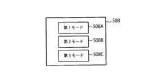
- FIG. 3 is a diagram illustrating an example of operation buttons of the hydrogen supply device 50.
- the control device 80 has a first mode, a second mode, and a third mode as control processing modes.
- the first mode is a mode for normal operation
- the second mode and the third mode are modes for performing an operation different from the normal operation.
- the control device 80 controls the first mode when the operator selects the first mode button 508A, performs the second mode control when the second mode button 508B is selected, and the third mode button 508C When selected, control in the third mode is performed. That is, when the supply amount of hydrogen is a predetermined hydrogen amount Q1 (for example, 48 Nm 3 ), the first mode is selected, and when supplying more hydrogen than the predetermined hydrogen amount Q1, the second mode, or Select the third mode.
- a predetermined hydrogen amount Q1 for example, 48 Nm 3
- FIG. 4 is a diagram schematically showing an example of the temperature of the cooling medium for each mode and an example of the temperature of hydrogen supplied from the hydrogen supply device 50.
- FIG. 5 is a diagram schematically showing the hydrogen supply time in the first mode and the second mode.
- a second hydrogen amount for example, 10 Nm 3 / min
- the control device 80 further has a third mode for shifting from the first mode to the second mode when the temperature of the cooling medium in the cooling medium tank 604 becomes higher than a predetermined temperature, for example, ⁇ 36 ° C.
- the third mode is used when supplying an indefinite amount of hydrogen exceeding Q1, which is the amount of hydrogen supplied in the first mode. For this reason, the third mode is used when hydrogen is supplied to a large fuel cell vehicle such as a bus.
- a large refrigerator has hydrogen supply capability to a large fuel cell vehicle in the first mode, but even a small refrigerator can supply a large amount of hydrogen to a large fuel cell vehicle.
- the control device 80 controls the cooling temperature of the cooling medium so that the temperature measured by the temperature meter 504 is ⁇ 33 ° C. or lower.
- the refrigerator 602 and the pumps 606 and 608 are controlled.
- control device 80 controls the temperature in the refrigerator 602 so that the temperature detected by the temperature meter 506 is ⁇ 40 ° C. At this time, the hydrogen supplied from the pressure accumulator unit 206 is lowered as it flows downstream of the heat exchanger 502, and the temperature of the supplied hydrogen becomes about ⁇ 37 ° C.
- the cooling medium rises in temperature as it flows to the downstream side of the heat exchanger 502.
- the degree of temperature rise of the cooling medium at this time varies depending on the temperature and flow rate of the cooling medium.
- the controller 80 controls the pump 606 so that the temperature detected by the temperature meter 508 is higher than the supply hydrogen temperature ⁇ 36 ° C. and lower than the predetermined value ⁇ 33 ° C. Then, when the temperature detected by the temperature measurement meter 506 is maintained at ⁇ 36 ° C. or lower and the control device 80 reaches Q1 that is the amount of supplied hydrogen in the first mode by the flow measurement device 610, the controller 80 starts from the pressure accumulator unit 206. The supply of hydrogen is stopped.
- the processing capability of the refrigerator 602 in the first mode will be described in more detail.
- the amount of hydrogen supplied to the fuel cell vehicle 802 at a time is set to a predetermined value or less such as Q1 as described above. For this reason, at the time of initial start-up, for example, hydrogen of Q1 or more needs to be stored in the accumulator unit 206.
- control is performed to maintain the temperature of the cooling medium at ⁇ 36 ° C. or less as described above when the amount of hydrogen of Q1 is supplied.
- the amount Q2 of the cooling medium that needs to be stored at the minimum in the first storage part of the cooling medium tank 604 in the first mode can be calculated backward.
- FIG. 6 is a diagram showing a relationship between a time P1 for the hydrogen generator 20 to generate a predetermined hydrogen amount Q1 and a time P2 for the refrigerator 602 to cool the heat amount Q2 ⁇ (T1 ⁇ T2).
- supply of hydrogen can be started according to time P1 during which the hydrogen generator 20 generates a predetermined hydrogen amount Q1.
- the hydrogen amount of Q1 is supplied as described above.
- the capacity of the refrigerator 602 can be reduced by making the upper limit processing capacity of the refrigerator 602 equal to the first refrigerating capacity.
- the heat quantity of Q2 ⁇ (T1 ⁇ T2) can be further reduced. For this reason, the capacity
- the capacity of the refrigerator 602 can be reduced by suppressing the cooling capacity per unit time at the initial start.
- FIG. 7 is a flowchart showing a processing example of the control device 80 in the third mode.
- the control device 80 acquires the temperature of the supplied hydrogen from the measured value of the temperature meter 504 (step S100).
- control device 80 determines whether or not the temperature of the supplied hydrogen is equal to or lower than a predetermined temperature ( ⁇ 33 ° C.) (step S102).
- a predetermined temperature ⁇ 33 ° C.
- control device 80 changes the control mode to the second mode (step S104).
- step S106 it is determined whether or not the hydrogen supply amount is less than the predetermined supply amount Q1 (step S106). If the hydrogen supply amount is less than the predetermined supply amount Q1 (YES in step S106), the processing from step S104 is repeated. On the other hand, when it is equal to or greater than the predetermined supply amount (NO in step S106), the entire process is terminated.
- the first refrigeration capacity of the refrigerator 602 is made to correspond to the generation time in which the hydrogen generator 20 generates a predetermined amount of hydrogen supplied from the supply device 80. Thereby, the cooling capacity per unit time can be suppressed, and the capacity of the refrigerator 602 can be reduced.
Landscapes
- Engineering & Computer Science (AREA)
- Mechanical Engineering (AREA)
- General Engineering & Computer Science (AREA)
- Filling Or Discharging Of Gas Storage Vessels (AREA)
- Fuel Cell (AREA)
Abstract
本実施形態に係る水素供給システムは、水素を生成する水素生成装置と、水素生成装置により生成された水素を貯蔵する水素貯蔵装置と、貯蔵された水素を供給する水素供給装置と、冷却媒体を冷却する冷却装置と、冷却装置を制御する制御装置と、を備え、冷却装置は、冷却媒体を貯蔵するタンクと、貯蔵される冷却媒体を冷却する冷凍機と、を有し、冷凍機の容量は、所定量の水素を水素生成装置が生成する生成時間に応じた容量以上にする。
Description
本発明の実施形態は、水素供給システム、及び水素供給システムの制御方法に関する。
化石燃料の枯渇、および大気中への二酸化炭素の放出による地球温暖化への対策が様々な産業部門で推進されている。この化石燃料で駆動される内燃機関車両の代替として、水素による燃料電池発電を介してポンプを駆動する燃料電池自動車(FCV:Fuel Cell Vehicle)の導入検討が進められている。このような、燃料電池自動車を普及させるためには、ガソリンスタンドに代わり水素供給システムの整備が必要となる。
1日に10台以上の燃料電池自動車に水素の供給を行なう大規模な水素供給システムの他に、1日に1台から数台の燃料電池自動車に水素の供給を行なう小規模な水素供給システムも計画されている。このような水素供給システムでは、水素供給システムをより小型化させることも重要視されている。この水素供給システムにおいて、水素を燃料電池自動車に供給する際の温度上昇を抑制するために、水素は冷却媒体により予め冷却される。
ところが、1日に1台から数台の燃料電池自動車に水素の供給を行なうためには、冷却媒体を冷却する冷凍機の容量が一定以上必要となり、水素供給システムが大型化してしまう。
本発明が解決しようとする課題は、冷却媒体を冷却する冷凍機の容量を小型化可能な水素供給システム、及び水素供給システムの制御方法を提供することである。
本実施形態に係る水素供給システムは、水素を生成する水素生成装置と、水素生成装置により生成された水素を貯蔵する水素貯蔵装置と、貯蔵された水素を供給する水素供給装置と、水素供給装置から供給される水素を冷却するために用いる冷却媒体を冷却する冷却装置と、冷却装置を制御する制御装置と、を備え、冷却装置は、冷却媒体を貯蔵するタンクと、タンクに貯蔵される冷却媒体を冷却する冷凍機と、を有し、冷凍機の容量は、水素供給装置から供給する所定量の水素を水素生成装置が生成する生成時間に応じた容量以上にする。
本発明によれば、冷凍機の容量を小型化できる。
以下、本発明の実施形態に係る水素供給システム、及び水素供給システムの制御方法について、図面を参照しながら詳細に説明する。なお、以下に示す実施形態は、本発明の実施形態の一例であって、本発明はこれらの実施形態に限定して解釈されるものではない。また、本実施形態で参照する図面において、同一部分又は同様な機能を有する部分には同一の符号又は類似の符号を付し、その繰り返しの説明は省略する場合がある。また、図面の寸法比率は説明の都合上実際の比率とは異なる場合や、構成の一部が図面から省略される場合がある。
(一実施形態)
図1は、実施形態に係る水素供給システム1の全体構成を示すブロック図である。この図1に示すように水素供給システム1は、水素の供給が可能なシステムであり、電力供給装置10と、水素生成装置20と、冷却水供給装置30と、水素貯蔵装置40と、水素供給装置50と、冷却装置60と、外部水素供給装置70と、制御装置80とを備えて構成されている。図1では、更に系統電力800と、燃料電池自動車802とを図示している。
図1は、実施形態に係る水素供給システム1の全体構成を示すブロック図である。この図1に示すように水素供給システム1は、水素の供給が可能なシステムであり、電力供給装置10と、水素生成装置20と、冷却水供給装置30と、水素貯蔵装置40と、水素供給装置50と、冷却装置60と、外部水素供給装置70と、制御装置80とを備えて構成されている。図1では、更に系統電力800と、燃料電池自動車802とを図示している。
電力供給装置10は、水素生成装置20を含む水素供給システム1に電力を供給する。この電力供給装置10は、再生可能エネルギー発電装置102と、パワーコンディショナ装置104と、分電盤106とを有する。
再生可能エネルギー発電装置102は、例えば太陽光発電装置であり、再生可能エネルギーを利用して発電を行う。太陽光発電装置は、太陽電池を含み、太陽電池を用いた光電変換により発電を行う。
パワーコンディショナ装置104は、例えばコンバータを含んで構成される。このコンバータは、再生可能エネルギー発電装置102が出力した直流電力を所定の交流電力に変換する。分電盤106は、パワーコンディショナ装置104又は系統電力(商用電源)800から供給される電力を分電し、水素生成装置20を含む水素供給システム1に供給する。
水素生成装置20は、水素を生成する。この水素生成装置20は、例えば固体高分子水電解装置であり、水を電気分解することにより水素を生成する。本実施形態に係る水素生成装置20には、外部から供給された水に電圧を印加することにより水素と酸素に分解するが、これに限定されず、メタンを含む天然ガスなどから水素を生成してもよい。水素生成装置20により生成された水素は、水素貯蔵装置40に供給される。また、水素生成装置20には、再生可能エネルギー発電装置102が出力した電力及び系統電力800の少なくとも一方から電力が供給されるように構成されている。水素生成装置20は、例えば48Nm3/日の水素を生成する。
冷却水供給装置30は、冷却水を水素生成装置20と水素貯蔵装置40の圧縮機204とに供給する。但し、冷却媒体は液体とは限らない。水素生成装置20と水素貯蔵装置40の圧縮機204とは気体による冷却方法でも良い。
水素貯蔵装置40は、水素生成装置20及び外部水素供給装置70から供給される水素を蓄え、圧縮・貯蔵する。この水素貯蔵装置40は、バッファタンク202と、圧縮機204と、蓄圧器ユニット206とを有する。
バッファタンク202は、水素流量の安定化のために用いられる。このバッファタンク202は、水素生成装置20及び外部水素供給装置70から供給される水素を一旦蓄え、圧縮機204に供給する。
圧縮機204は、例えば往復動圧縮機であり、駆動部と圧縮部とを有している。駆動部の動力により圧縮部のピストンが駆動されてシリンダ内の水素が圧縮される。圧縮機204から吐出された水素は、冷却水供給装置30から供給された冷却水により冷却される。この圧縮機204は、例えば82MPaまで水素を圧縮する。
蓄圧器ユニット206は、例えば同じ設計圧力の複数、例えば3基の蓄圧器を有する。複数の蓄圧器には、圧縮機204から吐出された水素ガスが貯蔵される。また、蓄圧器ユニット206は、水素供給装置50に水素を供給する。この蓄圧器ユニット206の容量は例えば、300L×3基であり、貯蔵量は、例えば655.0Nm3である。
水素供給装置50は、水素をタンク搭載車両である車両802に充填する。水素供給装置50は、ディスペンサと呼ばれる場合がある。冷却装置60は、水素供給装置50から供給される水素を冷却するために用いる冷却媒体を冷却する。水素供給装置50及び冷却装置60の詳細な構成は後述する。
外部水素供給装置70は、水素生成装置20が生成する水素以外の水素、例えば再エネ水素などを貯蔵し、水素貯蔵装置40に供給する。外部水素供給装置70は、高圧水素カードル702や、水素吸蔵合金ユニット704を有する。外部水素供給装置70は、接続状態、又は、非接続の状態にすることが可能である。このため、例えば水素生成装置20が生成する水素が不足する可能性がある場合などに、予備的に装着して使用してもよい。
高圧水素カードル702は、水素が充填されたガス貯蔵容器を複数本束ねたものである。高圧水素カードル702は、水素供給システム1において、水素の供給源として利用される。すなわち、高圧水素カードル702から供給される水素は、更にバッファタンク202に供給される。
水素吸蔵合金ユニット704は、冷却されると水素を吸蔵し、加熱されると水素を放出する水素吸蔵合金を利用したユニットである。水素吸蔵合金ユニット704における単位時間あたりの水素の吸蔵及び放出は、水素吸蔵合金ユニット704に与える温度によって制御可能である。水素吸蔵合金ユニット704は、高圧水素カードル702と同様に、水素供給システム1において、水素の供給源として利用される。なお、本実施形態に係る外部水素供給装置70は、高圧水素カードル702及び水素吸蔵合金ユニット704を有するが、これに限定されず、高圧水素カードル702及び水素吸蔵合金ユニット704の内の一方を有して構成してもよい。
制御装置80は、例えば処理回路を含んで構成される基盤であり、水素供給システム1全体の制御を行う。制御装置80による制御の詳細は後述する。なお、本実施形態においては、処理回路は、例えば、プロセッサにより構成される。ここで、プロセッサという文言は、例えば、CPU(Central Processing Unit)、GPU(Graphics Processing Unit)、或いは、特定用途向け集積回路(Application Specific Integrated Circuit: ASIC)、プログラマブル論理デバイス(例えば、単純プログラマブル論理デバイス(Simple Programmable Logic Device: SPLD)、複合プログラマブル論理デバイス(Complex Programmable Logic Device: CPLD)、及び、フィールドプログラマブルゲートアレイ(Field Programmable Gate Array: FPGA)等の回路を意味する。プロセッサは、記憶回路に保存されたプログラムを読み出して実行することにより機能を実現する。
ここで、水素供給装置50及び冷却装置60の詳細な構成を説明する。図2は、水素供給装置50及び冷却装置60の詳細な構成を示すブロック図である。図2に示すように、水素供給装置50は、冷却媒体と、温度測定計504、506、508を有する。また、冷却装置60は、冷凍機602と、冷却媒体タンク604と、ポンプ606、608と、流量測定計610と、を備える。
熱交換器502は、蓄圧器ユニット206から供給される水素を冷却媒体との間で熱交換させて冷却する。温度測定計504は、熱交換器502から供給される水素の温度を測定する。温度測定計506は、冷却媒体タンク604から供給される冷却媒体の温度を測定する。温度測定計508は、熱交換後の冷却媒体の温度を測定する。
冷凍機602は、冷却媒体タンク604に貯蔵される冷却媒体を冷却する。冷却媒体は、非蒸発性の不凍液であり、例えば、ブライン、エチレングリコール水や、フッ素系の液体等である。
冷凍機602は、熱交換器502で水素との熱交換により昇温した冷却媒体を低温の代替フロン等の冷媒との間で熱交換させることにより、冷却する。冷凍機602は、冷媒の温度を変更することにより冷却媒体の冷却後の温度を制御する。
冷却媒体タンク604は、冷却媒体を貯留する。冷却媒体タンク604は、冷凍機602から吐出された冷却後の冷却媒体を貯留する第1貯留部と、熱交換器502から排出された熱交換後の冷却媒体を貯留する第2貯留部を有する。第1貯留部には、配管を介して冷凍機602から冷却後の冷却媒体が供給され、この冷却後の冷却媒体は熱交換器502に供給される。第2貯留部には、配管を介して熱交換器502による熱交換後の冷却媒体が供給され、この熱交換後の冷却媒体は冷凍機602に供給される。なお、本実施形態に係る冷却媒体タンク604がタンクに対応する。
ポンプ606は、第1貯留部に貯留された冷却媒体を吸引し、熱交換器502へ供給する。このポンプ606は、単位時間当たりの冷却媒体の送出流量を変更可能である。
ポンプ608は、第2貯留部に貯留された冷却媒体を吸引し、冷凍機602へ供給する。このポンプ608は、単位時間当たりの冷却媒体の送出流量を変更可能である。流量測定計610は、水素供給装置50から燃料電池自動車802に供給される水素の量を計測する。
ここで、図3乃至図6に基づき、制御装置80の制御処理の詳細を説明する。
図3は、水素供給装置50の操作ボタンの一例を示す図である。図3に示すように、制御装置80は、制御処理のモードとして、第1モード、第2モード、および第3モードを有する。第1モードは通常運用時のモードであり、第2モード、および第3モードは、通常運用と異なる運用を行う場合のモードである。制御装置80は、操作者に第1モードボタン508Aが選択されると第1モードの制御を行い、第2モードボタン508Bが選択されると第2モードの制御を行い、第3モードボタン508Cが選択されると第3モードの制御を行う。すなわち、水素の供給量が所定の水素量Q1(例えば48Nm3)である場合に、第1モードを選択し、所定の水素量Q1よりも多くの水素を供給する場合に、第2モード、又は第3モードを選択する。
図3は、水素供給装置50の操作ボタンの一例を示す図である。図3に示すように、制御装置80は、制御処理のモードとして、第1モード、第2モード、および第3モードを有する。第1モードは通常運用時のモードであり、第2モード、および第3モードは、通常運用と異なる運用を行う場合のモードである。制御装置80は、操作者に第1モードボタン508Aが選択されると第1モードの制御を行い、第2モードボタン508Bが選択されると第2モードの制御を行い、第3モードボタン508Cが選択されると第3モードの制御を行う。すなわち、水素の供給量が所定の水素量Q1(例えば48Nm3)である場合に、第1モードを選択し、所定の水素量Q1よりも多くの水素を供給する場合に、第2モード、又は第3モードを選択する。
図4は、各モードに関する冷却媒体の温度例と、水素供給装置50から供給される水素の温度例とを模式的に示す図である。縦軸は温度(℃)を示している。より詳細には、第1温度T1=25℃(常温での冷却媒体の温度)、第2温度T2=-40℃(冷却媒体の目標温度)、第3温度T3は、T1=25℃からT2=-40℃までの間の温度(例えば、第2温度からFCVに水素を充填し上昇した冷却媒体の温度)である。また、第4温度T4=―33℃(第1モードの供給される水素の上限温度)であり、第5温度T5=―26℃(第2モードの供給される水素の上限温度)である。
図5は、第1モード、および第2モードの水素供給時間を模式的に示す図である。第1モードは、水素供給装置50から、例えば第2温度T2=-40℃から第4温度T4=―33℃以下の水素を単位時間あたりに第1水素量(例えば16Nm3/分)で供給するモードである。より具体的には、第1モードでは、第4温度T4=―33℃以下の所定の水素量Q1を所定時間3分以内で供給するモードである。
第2モードは、例えば第5温度T5=―26℃以下の水素を単位時間あたりに第2水素量(例えば10Nm3/分)供給するモードである。これから分かるように、冷却媒体を第1モードと同等の第2温度T2=-40℃まで冷却した場合には、第1モードにおける所定の供給水素量Q1よりも多くの水素を供給することが可能である。
制御装置80は、冷却媒体タンク604内の冷却媒体の温度が所定温度、例えば-36℃よりも高くなった場合に、第1モードから第2モードに移行する第3モードを更に有する。第3モードは、第1モードの供給水素量であるQ1を超える不定量の水素を供給する場合に使用される。このため、第3モードは、例えばバスなどの大型の燃料電池車両に水素を供給する場合などに使用される。大型の冷凍機では、第1モードで大型の燃料電池車両への水素供給能力を有するが、小型の冷凍機でも、大型の燃料電池車両に多くの水素を供給することが可能である。
ここで、第1モードでの冷却装置60の制御例を説明する。制御装置80は、温度測定計504での測定温度が-33℃以下になるように冷却媒体の冷却温度を制御する。冷凍機602及びポンプ606、608を制御する。
より詳細には、制御装置80は、温度測定計506による検出温度が-40℃になるように冷凍機602における温度制御を行う。この際、蓄圧器ユニット206から供給された水素は、熱交換器502の下流側へ流れるに従って降温し、供給水素の温度は約-37℃になる。
冷却媒体は、熱交換器502の下流側へ流れるに従って昇温する。この時の冷却媒体の昇温の度合いは、冷却媒体の温度及び流量によって異なる。このため、制御装置80は、温度測定計508による検出温度が供給水素の温度-36℃よりも高くなり、且つ、所定値-33℃よりも低くなるようにポンプ606の制御を行う。そして、制御装置80は、温度測定計506による検出温度が―36℃以下を維持させた状態で、流量測定計610により第1モードの供給水素量であるQ1に達すると、蓄圧器ユニット206からの水素の供給を停止する。
ここで、第1モードにおける冷凍機602の処理能力に関してより詳細に説明する。第1モードでは、燃料電池自動車802に一度に供給する水素量は、上述のようにQ1などの所定値以下に定められている。このため、初期始動時には蓄圧器ユニット206に、例えばQ1以上の水素が蓄えられている必要がある。
また、第1モードでは、水素供給装置50から水素を供給する際には、例えば3分以内に供給し、且つ水素の温度を例えばT4=-33℃以下に保つ必要がある。このため、制御装置80は、冷凍機602に対して、冷却媒体タンク604の第1貯留部に蓄えられる冷却媒体の温度を例えばT2=-40℃まで冷却する制御を行う。このとき、第1モードでは、Q1の水素量を供給した時点で冷却媒体の温度を上述のように-36℃以下に維持する制御を行う。
このような条件から第1モードにおいて冷却媒体タンク604の第1貯留部に、最低限蓄える必要がある冷却媒体の量Q2を逆算することができる。また、初期始動時に供給される冷却媒体の温度は、例えばT1=25℃である。これから分かるように、冷却媒体の量Q2に温度差(T1―T2)を乗算したQ2×(T1―T2)の熱量を冷却する必要がある。
図6は、水素生成装置20が所定の水素量Q1を生成する時間P1と、冷凍機602がQ2×(T1―T2)の熱量を冷却する時間P2との関係を示す図である。図6に示すように、制御装置80は、第1モードでは、初期始動時の熱量Q2×(T1―T2)を、時間P2=P1で冷却するように冷凍機602の制御を行う。これにより、水素生成装置20が所定の水素量Q1を生成する時間P1に合わせて、水素の供給を開始できる。このように、この場合の冷凍機602における第1冷凍能力は、水素供給装置50から供給する所定量の水素Q1を水素生成装置20が生成する生成時間P1に応じている。すなわち、この第1冷凍能力により冷却媒体タンク604に貯蔵される冷却媒体を第1温度T1=25℃から第2温度T2=-40℃まで冷却する時間P2が生成時間P1に対応する。
第1モードでは、初期始動が終了し、冷却媒体タンク604の第1貯留部に蓄えられる冷却媒体の温度が、第2温度T2=-40℃になると、上述のようにQ1の水素量を供給した時点の冷却媒体の温度は、-36℃以下に維持される。このため、冷凍機602が第1冷凍能力により冷却媒体の量Q2を第2温度T2=-40℃まで冷却する時間は、時間P2より短くなる。これらから分かるように、冷凍機602における上限の処理能力を第1冷凍能力と同等とすることで、冷凍機602の容量を小型化できる。なお、初期始動に供給される冷却媒体の温度T1が例えば-36℃であれば、Q2×(T1―T2)の熱量をより低下させることが可能となる。このため、冷凍機602の容量をより小型化できる。
このように、冷凍機602における初期始動時の単位時間あたりの冷却能力を最も高く設定する必要がある。換言すると、初期始動時の単位時間あたりの冷却能力を抑えることで、冷凍機602の容量を小型化可能となる。
図7は、第3モードにおける制御装置80の処理例を示すフローチャートである。ここでは、第1モードで水素の供給を開始した場合について説明する。図7に示すように、制御装置80は温度測定計504の測定値により、供給される水素の温度を取得する(ステップS100)。
次に、制御装置80は、供給される水素の温度が所定の温度(-33℃)以下であるか否かを判断する(ステップS102)。冷却媒体の温度が所定の温度(-33℃)以下である場合(ステップS102のYES)、ステップS100からの処理を繰り返す。
一方で、所定の温度(-33℃)より高くなった場合(ステップS102のNO)、制御装置80は、制御モードを第2モードに変更する(ステップS104)。
次に、水素供給量が所定の供給量Q1の未満か否かを判定し(ステップS106)、所定の供給量Q1の未満である場合(ステップS106のYES)、ステップS104からの処理を繰り返す。一方で、所定の供給量以上である場合(ステップS106のNO)、全体の処理を終了する。
以上のように本実施形態によれば、冷凍機602の第1冷凍能力を供給装置80から供給する所定量の水素を水素生成装置20が生成する生成時間に対応させることとした。これにより、単位時間あたりの冷却能力が抑制可能となり、冷凍機602の容量を小型化できる。
以上、本発明のいくつかの実施形態を説明したが、これらの実施形態は、例として提示したものであり、発明の範囲を限定することは意図していない。これら新規な実施形態は、その他の様々な形態で実施することが可能であり、発明の要旨を逸脱しない範囲で、種々の省略、置き換え、変更を行うことができる。これらの実施形態やその変形例は、発明の範囲や要旨に含まれると共に、特許請求の範囲に記載された発明とその均等の範囲に含まれる。
Claims (10)
- 水素を生成する水素生成装置と、
前記水素生成装置により生成された水素を貯蔵する水素貯蔵装置と、
前記貯蔵された水素を供給する水素供給装置と、
前記水素供給装置から供給される水素を冷却するために用いる冷却媒体を冷却する冷却装置と、
前記冷却装置を制御する制御装置と、を備え、
前記冷却装置は、
前記冷却媒体を貯蔵するタンクと、
前記タンクに貯蔵される前記冷却媒体を冷却する冷凍機と、を有し、
前記冷凍機の容量は、前記水素供給装置から供給する所定量の水素を前記水素生成装置が生成する生成時間に応じた容量以上にした、水素供給システム。 - 前記生成時間は、前記容量により前記タンクに貯蔵される冷却媒体を第1温度から第2温度まで冷却する時間であり、
前記制御装置は、前記第1温度以下で且つ前記第2温度よりも高い第3温度から前記第2温度まで冷却する場合の冷却時間を前記生成時間以内となるように前記冷凍機を制御する、水素供給システム。 - 前記容量は、前記水素供給装置から供給する所定量の水素を前記生成時間に応じた容量に対応する、請求項1又は2に記載の水素供給システム。
- 前記水素供給装置は、前記水素供給装置から供給する水素を前記冷却媒体により所定温度まで冷却する熱交換器を更に有する、請求項1乃至3のいずれか一項に記載の水素供給システム。
- 前記第2温度よりも高い第4温度以下の水素を単位時間あたりに第1水素量を供給する第1モードと、前記第4温度よりも高い第5温度以下の水素を前記単位時間あたりに前記第1水素量より少ない第2水素量を供給する第2モードと、を有し、
前記制御装置は、前記第1モードでは、前記冷凍機を前記第1冷凍能力により運転させる請求項1乃至4のいずれか一項に記載の水素供給システム。 - 前記制御装置は、前記タンク内の冷却媒体の温度が所定温度よりも高くなった場合に、前記第1モードから前記第2モードに移行する第3モードを更に有する、請求項5に記載の水素供給システム。
- 前記第1モード、前記第2モード、及び前記第3モードの内のいずれかを選択する操作を行う操作部を更に備え、
前記制御装置は、前記操作部により選択されたモードの制御を行う、請求項6に記載の水素供給システム。 - 前記第1モードでは所定の水素量を供給し、前記第3モードでは、前記所定の水素量よりも多くの水素を供給する、請求項6に記載の水素供給システム。
- 前記冷凍機に電力を供給する系統電力が停電した場合に、前記制御装置は、前記水素供給装置から供給する水素の量に基づき、前記第1モードから前記第2モードに移行する、請求項5に記載の水素供給システム。
- 水素を生成する水素生成装置と、前記水素生成装置により生成された水素を貯蔵する水素貯蔵装置と、前記貯蔵された水素を供給する水素供給装置と、前記水素供給装置から供給する水素を冷却するために用いる冷却媒体を冷却する冷却装置と、前記冷却装置を制御する制御装置と、を備え、
前記冷却装置は、前記冷却媒体を貯蔵するタンクと、前記タンクに貯蔵する前記冷却媒体を冷却する冷凍機と、を有し、前記冷凍機の容量は、前記水素供給装置から供給する所定量の水素を前記水素生成装置が生成する生成時間に応じた容量以上にしており、前記容量により前記冷却媒体を第1温度から第2温度まで冷却する時間が前記生成時間に対応する水素供給システムの制御方法であり、
前記第1温度以下で且つ前記第2温度よりも高い第3温度から前記第2温度まで冷却する場合の冷却時間を前記生成時間以内となるように前記冷凍機を制御する、水素供給システムの制御方法。
Priority Applications (2)
| Application Number | Priority Date | Filing Date | Title |
|---|---|---|---|
| JP2020520998A JP6957748B2 (ja) | 2018-05-25 | 2018-05-25 | 水素供給システム、及び水素供給システムの制御方法 |
| PCT/JP2018/020228 WO2019225019A1 (ja) | 2018-05-25 | 2018-05-25 | 水素供給システム、及び水素供給システムの制御方法 |
Applications Claiming Priority (1)
| Application Number | Priority Date | Filing Date | Title |
|---|---|---|---|
| PCT/JP2018/020228 WO2019225019A1 (ja) | 2018-05-25 | 2018-05-25 | 水素供給システム、及び水素供給システムの制御方法 |
Publications (1)
| Publication Number | Publication Date |
|---|---|
| WO2019225019A1 true WO2019225019A1 (ja) | 2019-11-28 |
Family
ID=68617264
Family Applications (1)
| Application Number | Title | Priority Date | Filing Date |
|---|---|---|---|
| PCT/JP2018/020228 Ceased WO2019225019A1 (ja) | 2018-05-25 | 2018-05-25 | 水素供給システム、及び水素供給システムの制御方法 |
Country Status (2)
| Country | Link |
|---|---|
| JP (1) | JP6957748B2 (ja) |
| WO (1) | WO2019225019A1 (ja) |
Cited By (1)
| Publication number | Priority date | Publication date | Assignee | Title |
|---|---|---|---|---|
| WO2025013263A1 (ja) * | 2023-07-12 | 2025-01-16 | 本田技研工業株式会社 | 燃料ガス充填装置 |
Citations (5)
| Publication number | Priority date | Publication date | Assignee | Title |
|---|---|---|---|---|
| JPH02263055A (ja) * | 1988-12-23 | 1990-10-25 | Toshiba Corp | 冷凍サイクル装置 |
| WO2011013214A1 (ja) * | 2009-07-29 | 2011-02-03 | トヨタ自動車株式会社 | ガス充填システム |
| JP2012237437A (ja) * | 2011-04-26 | 2012-12-06 | Kobe Steel Ltd | 水素ステーション |
| JP2017150661A (ja) * | 2016-02-23 | 2017-08-31 | 株式会社日立プラントメカニクス | 高圧水素の膨張タービン・コンプレッサ式充填システムの制御方法 |
| JP2017166635A (ja) * | 2016-03-17 | 2017-09-21 | 東京瓦斯株式会社 | 水素ステーション |
-
2018
- 2018-05-25 WO PCT/JP2018/020228 patent/WO2019225019A1/ja not_active Ceased
- 2018-05-25 JP JP2020520998A patent/JP6957748B2/ja not_active Expired - Fee Related
Patent Citations (5)
| Publication number | Priority date | Publication date | Assignee | Title |
|---|---|---|---|---|
| JPH02263055A (ja) * | 1988-12-23 | 1990-10-25 | Toshiba Corp | 冷凍サイクル装置 |
| WO2011013214A1 (ja) * | 2009-07-29 | 2011-02-03 | トヨタ自動車株式会社 | ガス充填システム |
| JP2012237437A (ja) * | 2011-04-26 | 2012-12-06 | Kobe Steel Ltd | 水素ステーション |
| JP2017150661A (ja) * | 2016-02-23 | 2017-08-31 | 株式会社日立プラントメカニクス | 高圧水素の膨張タービン・コンプレッサ式充填システムの制御方法 |
| JP2017166635A (ja) * | 2016-03-17 | 2017-09-21 | 東京瓦斯株式会社 | 水素ステーション |
Cited By (1)
| Publication number | Priority date | Publication date | Assignee | Title |
|---|---|---|---|---|
| WO2025013263A1 (ja) * | 2023-07-12 | 2025-01-16 | 本田技研工業株式会社 | 燃料ガス充填装置 |
Also Published As
| Publication number | Publication date |
|---|---|
| JP6957748B2 (ja) | 2021-11-02 |
| JPWO2019225019A1 (ja) | 2021-05-13 |
Similar Documents
| Publication | Publication Date | Title |
|---|---|---|
| JP6346013B2 (ja) | 高温水蒸気電解を用いた水素製造装置及び方法 | |
| JP5374022B2 (ja) | 水素供給ステーション | |
| US10612512B2 (en) | Energy storage and power generation system and method | |
| JP2014508261A (ja) | 水素充填方法及びシステム | |
| US11391415B1 (en) | Method for minimizing power demand for hydrogen refueling station | |
| JP2016121675A (ja) | 圧縮空気貯蔵発電装置及び圧縮空気貯蔵発電方法 | |
| JP2021012013A (ja) | 液体水素の生成のためのプロセス及びプラント | |
| US11608938B2 (en) | System and method for refueling and backup power generation | |
| JP2018062991A (ja) | 高圧水素製造システム | |
| JP6553523B2 (ja) | 電力供給システム | |
| JP2017219152A (ja) | 水素供給施設および水素供給方法 | |
| JP6957748B2 (ja) | 水素供給システム、及び水素供給システムの制御方法 | |
| CN108350807A (zh) | 压缩空气贮存发电装置及压缩空气贮存发电方法 | |
| JP2008291817A (ja) | 発電プラント及び発電プラントの発電方法 | |
| CN110425413B (zh) | 一种大规模低能耗阶梯储氢系统及方法 | |
| JP2019120357A (ja) | 液化天然ガス供給システム及び液化天然ガス供給方法 | |
| JP2018054032A (ja) | 高圧水素製造システム | |
| JP2017198236A (ja) | 高圧水素製造システム | |
| RU2455394C1 (ru) | Электролизная система заправки водородом, работающая при высоком давлении, и способ ее эксплуатации | |
| JP2017032122A (ja) | 水素プレクールシステム | |
| JP4310806B2 (ja) | 圧縮水素ガス生成装置 | |
| CN118008469A (zh) | 一种恒压储气库系统及构建方法 | |
| JP6306397B2 (ja) | 水素ステーション | |
| WO2019225020A1 (ja) | 水素・電力供給システム、及び水素・電力供給システムの制御方法 | |
| CN115750017B (zh) | 液态空气储能耦合制氨发电系统及方法 |
Legal Events
| Date | Code | Title | Description |
|---|---|---|---|
| 121 | Ep: the epo has been informed by wipo that ep was designated in this application |
Ref document number: 18920036 Country of ref document: EP Kind code of ref document: A1 |
|
| ENP | Entry into the national phase |
Ref document number: 2020520998 Country of ref document: JP Kind code of ref document: A |
|
| NENP | Non-entry into the national phase |
Ref country code: DE |
|
| 122 | Ep: pct application non-entry in european phase |
Ref document number: 18920036 Country of ref document: EP Kind code of ref document: A1 |