WO2019224939A1 - 乗客コンベア - Google Patents
乗客コンベア Download PDFInfo
- Publication number
- WO2019224939A1 WO2019224939A1 PCT/JP2018/019833 JP2018019833W WO2019224939A1 WO 2019224939 A1 WO2019224939 A1 WO 2019224939A1 JP 2018019833 W JP2018019833 W JP 2018019833W WO 2019224939 A1 WO2019224939 A1 WO 2019224939A1
- Authority
- WO
- WIPO (PCT)
- Prior art keywords
- support device
- truss
- state
- holding state
- holding
- Prior art date
- Legal status (The legal status is an assumption and is not a legal conclusion. Google has not performed a legal analysis and makes no representation as to the accuracy of the status listed.)
- Ceased
Links
Images








Classifications
-
- B—PERFORMING OPERATIONS; TRANSPORTING
- B66—HOISTING; LIFTING; HAULING
- B66B—ELEVATORS; ESCALATORS OR MOVING WALKWAYS
- B66B23/00—Component parts of escalators or moving walkways
Definitions
- the present invention relates to a passenger conveyor equipped with a truss.
- the passenger conveyor has an escalator installed between the upper and lower floors of the building.
- One end of the truss of the escalator described in Patent Document 1 is fixed to the building by a fixing pin.
- the other end of the escalator truss is supported to be slidable with respect to the building. That is, one support point of the escalator truss is a fixed support structure.
- the other support point is a slidable support structure.
- the present invention has been made to solve the above problems. Specifically, the object is to provide a passenger conveyor that does not require restoration work even if there is a large shaking.
- a passenger conveyor according to the present invention is installed between a first fixed portion and a second fixed portion in a building, and is provided on a truss having a first truss end portion and a second truss end portion, a first fixed portion, A first support device that supports one truss end portion, and a second support device that is provided in the second fixing portion and supports the second truss end portion, and the first support device includes a first fixing portion and a first fixing device.
- the truss end portion can be switched between a first holding state in which the truss end portion is not relatively moved and a first release state in which the truss end portion is relatively movable in the horizontal direction.
- the second support device includes the second fixing portion and the second truss.
- the first support device can be switched between a second holding state in which the end portion is not relatively moved and a second release state in which the end portion is relatively movable in the horizontal direction.
- the passenger conveyor according to the present invention at least one of the first holding state of the first support device and the second holding state of the second support device is generated. That is, at least one of the first support device and the second support device always holds the truss in the building regardless of shaking. Therefore, the passenger conveyor according to the present invention does not require a restoration work after the building is shaken.
- Embodiment 1 The escalator which is a passenger conveyor which concerns on Embodiment 1 of this invention is demonstrated.
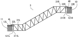
- FIG. 1 is a schematic diagram of a building 1 in which an escalator 2 is installed.
- the escalator 2 is provided across the upper floor 10 on the third floor and the lower floor 11 on the second floor in the building 1.
- the right direction in FIG. 1 be a positive direction about the direction in which a building inclines at the time of occurrence of a shake.
- FIG. 2 is a schematic diagram showing an installed state of the escalator 2 of FIG.
- the upper floor 10 is provided with a first fixing portion 12R.
- the lower floor 11 is provided with a second fixing portion 12L.
- the position of the first fixing part 12R is a position higher than the position of the second fixing part 12L and is a position that is separated in the horizontal direction with respect to the position of the second fixing part 12L.
- the horizontal distance between the first fixed portion 12R and the second fixed portion 12L is larger than a reference distance described later.
- the first fixed portion 12R and the second fixed portion 12L move relative to each other. Therefore, the horizontal distance between the first fixed part 12R and the second fixed part 12L changes.
- the amount of change in the horizontal distance varies depending on the magnitude of the earthquake and the structure of the building 1.
- the upper limit value and the lower limit value of the horizontal distance are both within the reference distance or more.
- the first shaking state is a small shaking state that falls within the range, and the horizontal distance changes so that the upper limit value of the horizontal distance is larger than the reference distance and the lower limit value of the horizontal distance is smaller than the reference distance. This state is the second shaking state.
- the escalator 2 includes a truss 3, and a first support device 4R and a second support device 4L that support the truss 3.
- the truss 3 is configured by combining a plurality of steel beams.
- the truss 3 has a first truss end portion 31 ⁇ / b> R located at one end of the truss 3 and a second truss end portion 31 ⁇ / b> L located at the other end of the truss 3.
- the first truss end portion 31R includes a first support fitting 32R.
- the first fixed portion 12R of the building 1 is provided with a first fixed surface 121R that faces the first end surface 311R of the first truss end portion 31R of the truss 3.
- the second truss end portion 31L includes a second support fitting 32L.
- the second fixing portion 121L of the building 1 is provided with a second fixing surface 121L facing the second end surface 311L of the second truss end portion 31L of the truss 3.
- the first support device 4R is provided in the first fixing portion 12R.
- the first support device 4 ⁇ / b> R supports the first truss end portion 31 ⁇ / b> R of the truss 3. Thereby, the first truss end portion 31R of the truss 3 is supported by the first fixing portion 12R via the first support device 4R.
- the second support device 4L is provided in the second fixing portion 12L.
- the second support device 4 ⁇ / b> L supports the second truss end portion 31 ⁇ / b> L of the truss 3.
- the second truss end portion 31L of the truss 3 is supported by the second fixing portion 12L via the second support device 4L.
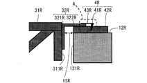
- FIG. 3 is a side view showing the first support device 4R of FIG.
- FIG. 4 is an enlarged view of a portion A in FIG.
- the first support fitting 32R is angle steel having an L-shaped cross section as shown in FIG.
- the first support fitting 32R includes a vertical connection portion 321R and a horizontal connection portion 322R.
- the cross-sectional shape of the first support fitting 32R is L-shaped by the vertical connection portion 321R and the horizontal connection portion 322R.
- the vertical connection portion 321R is fixed to the first end surface 311R of the first truss end portion 31R.
- the horizontal connection portion 322R extends from the upper end portion of the vertical connection portion 321R toward the first fixed portion 12R.
- the first support device 4R includes a first fitting member 41R, a first receiving member 42R, and a first elastic deformation member 43R.
- the first receiving member 42R is fixed to the first fixing portion 12R.
- the first receiving member 42R is a plate-like member having an upper surface portion 421R.
- a horizontal connection portion 322R of the first support fitting 32R is slidably mounted on the upper surface portion 421R of the first receiving member 42R.
- a first gap 13R is provided in the horizontal direction between the vertical connection portion 321R of the first support fitting 32R and the first fixing surface 121R of the first fixing portion 12R. The size of the first gap 13R is sufficiently large so that the vertical connection portion 321R and the first end surface 311R do not contact even in the second shaking state.
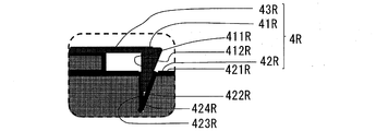
- a first groove 422R into which the first fitting member 41R is fitted is formed on the upper surface 421R of the first receiving member 42R.
- the cross-sectional shape of the first groove portion 422R viewed along the side view direction of the truss 3 is a right triangle including a groove vertical surface portion 423R and a groove inclined surface portion 424R.
- the groove vertical surface portion 423R is perpendicular to the upper surface portion 421R.
- the groove inclined surface portion 424R is inclined with respect to the upper surface portion 421R.
- the groove vertical surface portion 423R is located on the first truss end portion 31R side with respect to the groove inclined surface portion 424R.
- the width of the first groove portion 422R which is the distance between the groove vertical surface portion 423R and the groove inclined surface portion 424R, is wider at the opening above the first groove 422R, and is narrower toward the bottom.
- the first fitting member 41R includes a protrusion vertical surface portion 411R and a protrusion inclined surface portion 412R.
- the cross section of the first fitting member 41R in the side view of the escalator 2 is a right triangle.
- the protrusion vertical surface portion 411R is located on the first truss end portion 31R side with respect to the protrusion inclined surface portion 412R.
- the protrusion vertical surface portion 411R is perpendicular to the upper surface portion 421R of the first receiving member 42R, and the protrusion inclined surface portion 412R is the first receiving member 42R. It inclines with respect to the upper surface part 421R.
- the first elastic deformation member 43R is a leaf spring. One end of the first elastic deformation member 43R is fixed to the horizontal connection portion 322R of the first support fitting 32R. A first fitting member 41R formed separately from the first elastic deformation member 43R is provided at the other end of the first elastic deformation member 43R.
- the first elastic deformation member 43R and the first fitting member 41R may be integrally formed.
- the first fitting member 41R and the first groove portion 422R are fitted in a state where the protrusion vertical surface portion 411R and the groove vertical surface portion 423R are in contact with each other, and the protrusion inclined surface portion 412R and the groove inclined surface portion 424R are in contact with each other.
- the first gap 13R is generated.
- the first fitting member 41R and the first receiving member 42R are fitted in a state where the first elastic deformation member 43R is not elastically deformed.
- the first elastic deformation member 43R is elastically deformed when the first fitting member 41R slides up along the groove inclined surface portion 424R in a direction away from the first groove portion 422R.
- the first elastic deformation member 43R generates an elastic restoring force against the force in the direction in which the first fitting member 41R is disengaged from the first groove 422R. That is, the first elastic deformation member 43R biases the first fitting member 41R so that the first fitting member 41R is fitted into the first groove portion 422R by an elastic restoring force.
- the first elastic deformation member 43R pushes the first fitting member 41R in the direction in which the first fitting member 41R is pressed against the upper surface portion 421R. Energize.
- the first support device 4R holds the first fixing portion 12R and the first truss end portion 31R so as not to move relative to each other.
- This state is the first holding state.
- the first support device 4R releases the first fixing portion 12R and the first truss end portion 31R so as to be relatively movable in the horizontal direction. To do.
- This state is the first release state.
- the first support device 4R is capable of both switching from the first holding state to the first releasing state and switching from the first releasing state to the first holding state.
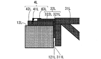
- FIG. 5 is a side view showing the second support device 4L of FIG.
- FIG. 6 is an enlarged view of a portion B in FIG.
- the second support fitting 32L is an angle steel having an L-shaped cross section.
- the second support fitting 32L includes a vertical connection portion 321L and a horizontal connection portion 322L.
- the cross-sectional shape of the second support fitting 32L is L-shaped by the vertical connection portion 321L and the horizontal connection portion 322L.
- the vertical connection portion 321L is fixed to the second end surface 311L of the second truss end portion 31L.
- the horizontal connection portion 322L extends from the upper end portion of the vertical connection portion 321L toward the second fixing portion 12L.
- the second support device 4L includes a second fitting member 41L, a second receiving member 42L, and a second elastic deformation member 43L.
- the second receiving member 42L is fixed to the second fixing portion 12L.
- the second receiving member 42L is a plate-like member having an upper surface portion 421L.
- the horizontal connection portion 322L of the second support fitting 32L is slidably mounted on the upper surface portion 421L of the second receiving member 42L.
- a second gap 13L is provided in the horizontal direction between the vertical connection portion 321L of the second support fitting 32L and the second fixing surface 121L of the second fixing portion 12L.
- the size of the second gap 13L is set such that the vertical connection portion 321L and the second end surface 311L are in contact with each other in the second shaking state.
- a second groove 422L into which the second fitting member 41L is fitted is formed on the upper surface 421L of the second receiving member 42L.
- the cross-sectional shape of the second groove portion 422L viewed along the side view direction of the truss 3 is a right triangle including the groove vertical surface portion 423L and the groove inclined surface portion 424L.
- the groove vertical surface portion 423L is perpendicular to the upper surface portion 421L.
- the groove inclined surface portion 424L is inclined with respect to the upper surface portion 421L.
- the groove inclined surface portion 424L is located on the second truss end portion 31L side with respect to the groove vertical surface portion 423L.
- the width of the second groove portion 422L which is the distance between the groove vertical surface portion 423L and the groove inclined surface portion 424L, is wide at the opening above the second groove portion 422L and narrows toward the bottom.
- the second fitting member 41L includes a protrusion vertical surface portion 411L and a protrusion inclined surface portion 412L.
- the cross section of the second fitting member 41L in the side view of the escalator 2 is a right triangle.
- the protrusion inclined surface portion 412L is located on the second truss end portion 31L side with respect to the protrusion vertical surface portion 411L.
- the protrusion vertical surface portion 411L is perpendicular to the upper surface portion 421L of the second receiving member 42L, and the protrusion inclined surface portion 412L is the second receiving member 42L. It inclines with respect to the upper surface part 421L.
- the second elastic deformation member 43L is a leaf spring. One end of the second elastic deformation member 43L is fixed to the horizontal connection portion 322L of the second support fitting 32L. A second fitting member 41L formed separately from the second elastic deformation member 43L is provided at the other end of the second elastic deformation member 43L.
- the second elastic deformation member 43L and the second fitting member 41L may be integrally formed.
- the second fitting member 41L and the second groove portion 422L are fitted in a state where the protrusion vertical surface portion 411L and the groove vertical surface portion 423L are in contact with each other and the protrusion inclined surface portion 412L and the groove inclined surface portion 424L are in contact with each other.
- the second fitting member 41L and the second receiving member 42L are fitted in a state where the second elastic deformation member 43L is not elastically deformed.
- the second elastic deformation member 43L is elastically deformed by the second fitting member 41L sliding up along the groove inclined surface portion 424L in a direction away from the second groove portion 422L.
- the second elastic deformation member 43L generates an elastic restoring force against the force in the direction in which the second fitting member 41L is detached from the second groove 422L. That is, the second elastic deformation member 43L biases the second fitting member 41L so that the second fitting member 41L is fitted into the second groove portion 422L by an elastic restoring force.
- the second elastic deformation member 43L pushes the second fitting member 41L in the direction in which the second fitting member 41L is pressed against the upper surface portion 421L. Energize.
- the second fitting member 41L In the state where the second fitting member 41L is fitted in the second groove portion 422L, the second truss end portion 31L is in contact with the second fixing portion 12L.
- the second fitting member 41L is disengaged from the second groove portion 422L, and a second gap 13L is generated between the second truss end portion 31L and the second fixing portion 12L.
- the second support device 4L holds the second fixing portion 12L and the second truss end portion 31L so as not to move relative to each other.
- This state is the second holding state.
- the second support device 4L releases the second fixing portion 12L and the second truss end portion 31L so as to be relatively movable in the horizontal direction. To do.
- This state is the second release state.
- the second support device 4L is capable of both switching from the second holding state to the second releasing state and switching from the second releasing state to the second holding state.
- the second fitting member 41L is detached from the second groove 422L. That is, when the truss 3 is installed and in the first swing state, the second support device 4L is in the second released state in which the second truss end portion 31L of the truss 3 can slide with respect to the second fixing portion 12L. . Therefore, in the case of the first shaking state, the horizontal connection portion 322L of the second support fitting 32L slides on the upper surface portion 421L of the second receiving member 42L.
- the reference distance between the first fixing portion 12R and the second fixing portion 12L is that the first fitting member 41R and the first groove portion 422R are fitted, and the second fitting member 41L and the second groove portion are fitted. This is the horizontal distance between the first fixed portion 12R and the second fixed portion 12L in a state where 422L is fitted.
- the reference distance is obtained by subtracting the interval of the second gap 13L provided when the truss 3 is installed from the horizontal distance between the first fixing part 12R and the second fixing part 12L when the truss 3 is installed. Distance.
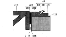
- FIG. 7 is a side view showing the first support device 4R when the horizontal distance between the first fixing portion 12R and the second fixing portion 12L in FIG. 2 is smaller than the reference distance.
- FIG. 8 is a side view showing the second support device 4L when the horizontal distance between the first fixing portion 12R and the second fixing portion 12L in FIG. 2 is smaller than the reference distance.
- the second truss end portion 31L not held in the building 1 approaches the second fixed portion 12L while shaking.
- the second truss end portion 31L comes into contact with the second fixing portion 12L.
- the second fitting member 41L is fitted with the second groove portion 422L of the second receiving member 42L. That is, the second support device 4L enters the second holding state.
- the second truss end portion 31L and the second fixing portion 12L cannot be moved relative to each other.
- the protrusion vertical surface portion 411L and the groove vertical surface portion 423L are vertical surfaces, the surfaces of the protrusion vertical surface portion 411L and the groove vertical surface portion 423L do not slip. Accordingly, the horizontal load in which the protrusion vertical surface portion 411L pushes the groove vertical surface portion 423L acts on the truss 3. That is, the movement that the building 1 shakes acts as a horizontal load on the second truss end portion 31L via the second truss end portion 31L and the second fixing portion 12L that move integrally. As a result, the truss 3 is pushed.
- a horizontal load acts between the projection inclined surface portion 412R of the first fitting member 41R and the groove inclined surface portion 424R of the first receiving member 42R in a direction approaching each other.
- the protrusion inclined surface portion 412R and the groove inclined surface portion 424R are inclined surfaces. Therefore, the projection inclined surface portion 412R relatively moves so as to slide up the groove inclined surface portion 424R due to the horizontal load acting between the protrusion inclined surface portion 412R and the groove inclined surface portion 424R.
- the first fitting member 41R is disengaged from the first groove portion 422R of the first receiving member 42R. Therefore, the first truss end portion 31R can move relative to the first fixed portion 12R.
- the second support device 4L switches from the second released state to the second holding state in the process of shaking the building 1. Further, at the same time that the second support device 4L is switched from the second release state to the second holding state, the first support device 4R is switched from the first holding state to the first release state. That is, in the second shaking state, the device that holds the truss 3 is switched from the second support device 4L to the first support device 4R.
- the first support device 4R and the second support device 4L operate as follows in response to a change in the horizontal distance between the first fixed portion 12R and the second fixed portion 12L.
- the first support device 4R is in the first holding state and the second support device 4L is in the second holding state. is there.
- the first support device 4R is in the first holding state
- the second support device 4L is in the second state. It is in a released state.
- the horizontal distance between the first fixing portion 12R and the second fixing portion 12L is smaller than the reference distance, the first support device 4R is in the first released state, and the second support device 4L is in the second state. It is a holding state.
- the horizontal load when the first support device 4R switches from the first holding state to the first release state is as follows.
- the horizontal load at which the first support device 4R is switched to the first released state includes the horizontal inertia force of the truss 3 acting on the truss 3 when the building 1 is shaking, and the second truss end 31L and the second truss 3 of the truss 3. It is greater than the horizontal load determined by both of the frictional forces with the support device 4L and less than the compressive strength of the truss 3.
- the horizontal load when the first support device 4R is switched from the first holding state to the first released state acts on the truss 3 as a compressive load.
- the horizontal load when the second support device 4L is switched from the second holding state to the second released state is as follows.
- the horizontal load at which the second support device 4L switches to the second released state is the horizontal inertia force of the truss 3 acting on the truss 3 when the building 1 is shaking, the first truss end portion 31R, and the first support device 4R. It is larger than the horizontal load determined by both of the frictional forces between the first support device 4R and the fracture strength of the first support device 4R.
- the horizontal load when the second support device 4L switches from the second holding state to the second released state acts on the truss 3 as a tensile load.
- FIG. 9 is a conceptual diagram showing the relationship between the shaking of the building 1 and the operations of the first support device 4R and the second support device 4L.
- FIGS. 9A to 9H the position of the second fixing portion 12L is fixed in each drawing for easy understanding.
- FIG. 9A shows a state when the truss 3 is installed.
- the first support device 4R is in the first holding state
- the second support device 4L is in the second release state.
- FIG. 9B shows the first support device 4R and the second support device 4L when the building 1 is tilted in the forward direction in the first shaking state.
- FIG. 9C shows the first support device 4R and the second support device 4L when the building 1 is tilted in the negative direction in the first shaking state.
- the horizontal distance between the first fixed portion 12R and the second fixed portion 12L is wider than when the truss 3 is installed as shown in FIG. 9B. .
- the truss 3 moves in the positive direction with respect to the second fixing portion 12L while the first support device 4R maintains the first holding state and the second support device 4L maintains the second release state.
- the second truss end portion 31L slides with respect to the second receiving member 42L.
- the second gap 13L between the vertical connection portion 321L of the second support fitting 32L and the second fixing surface 121L of the second fixing portion 12L is widened.
- the first support device 4R maintains the first holding state and the second support device 4L maintains the second released state. 3 moves in the negative direction.
- the second truss end portion 31L slides with respect to the second receiving member 42L, and the second gap 13L becomes narrower. That is, the horizontal distance between the first fixing portion 12R and the second fixing portion 12L is narrower than when the truss 3 is installed.
- FIG. 9D to FIG. 9H show the relationship between the shaking of the building 1 in the second shaking state and the states of the first supporting device 4R and the second supporting device 4L.
- the state of shaking of the building 1 is the second shaking state
- the building 1 shakes more greatly than in the first shaking state.
- FIG. 9D when the building 1 is tilted in the positive direction in the second shaking state, the horizontal distance between the first fixed portion 12R and the second fixed portion 12L becomes wider than when the truss 3 is installed. .
- the truss 3 moves in the forward direction while the first support device 4R maintains the first holding state and the second support device 4L maintains the second release state.
- the second truss end portion 31L side slides with respect to the second receiving member 42L.
- the second gap 13L between the vertical connection portion 321L of the second support fitting 32L and the second fixed surface 121L is wider than that in FIG. 9B, which is the first swing state.
- the length of the second receiving member 42L to which the vertical connection portion 321L is applied is set to a length that does not cause the truss 3 to drop off even when the vibration is maximum. Therefore, the allowance for the vertical connection portion 321L to be applied to the second receiving member 42L is sufficiently secured, and the truss 3 is always supported by the building 1 even if the shaking occurs.
- FIG. 9 (E) shows a state immediately after FIG. 9 (D).
- the building 1 is inclined in the negative direction, the horizontal distance between the first fixed portion 12R and the second fixed portion 12L is reduced.
- the truss 3 moves in the negative direction while the first support device 4R maintains the first holding state and the second support device 4L maintains the second release state. Therefore, the second truss end portion 31L slides with respect to the second receiving member 42L.
- the second gap 13L between the vertical connection portion 321L of the second support fitting 32L and the second fixed surface 121L disappears, and the vertical connection portion 321L and the second fixed surface 121L come into contact with each other.
- the horizontal distance between the first fixed portion 12R and the second fixed portion 12L is the reference distance.
- the second support device 4L is switched from the second released state to the second holding state. That is, the second support device 4L enters the second holding state while the first support device 4R remains in the first holding state. Accordingly, the movement of the second fixing portion 12L due to the shaking is transmitted to the truss 3.
- a horizontal load is applied to the truss 3 from the second fixing portion 12L via the second support device 4L. Therefore, a horizontal load starts to be applied to the first support device 4R via the truss 3.
- FIG. 9 (F) shows a state immediately after FIG. 9 (E).
- the horizontal load acting on the truss 3 becomes larger than the state shown in FIG.
- the first support device 4R is in the first holding state
- the horizontal load acting on the truss 3 acts as a compressive load on the truss 3.
- the first support device 4R holds the first holding before reaching the compressive strength load of the truss 3. The state is switched to the first release state.
- the truss 3 further moves with respect to the first fixing portion 12R, and the first truss end portion 31R slides with respect to the first receiving member 42R. Therefore, the horizontal distance between the first fixing portion 12R and the second fixing portion 12L is further narrower than the state of FIG. 9E, and the first gap 13R between the vertical connection portion 321R and the first fixing surface 121R. Becomes narrower.
- the first support device 4R is switched to the first released state, the first truss end portion 31R slides with respect to the first fixed portion 12R, so that the compressive load acting on the truss 3 is drastically reduced.
- FIG. 9 (G) shows a state immediately after FIG. 9 (F).
- the building 1 is in a state of starting to sway in the opposite direction to FIG.
- the first truss end portion 31R slides in the positive direction, and the first gap 13R widens.
- the first fitting member 41R reaches the first groove 422R, and the first fitting member 41R is fitted into the first groove 422R. That is, the first support device 4R is switched from the first released state to the first holding state.
- FIG. 9 (H) shows a state where the shaking of the building 1 has subsided from the state of FIG. 9 (G).
- the building 1 returns to the installation state by further shaking in the forward direction from the state of FIG.
- the truss 3 moves in the forward direction while the first support device 4R maintains the holding state and the second support device 4L maintains the holding state. Therefore, the second fitting member 41L is detached from the second groove 422L. That is, the first support device 4 ⁇ / b> R returns to the same second released state as when the truss 3 is installed.
- the second truss end 31L slides relative to the second receiving member 42L.
- the second gap 13L becomes wider than the state of FIG.
- the distance between the first fixing portion 12R and the second fixing portion 12L is wider than the state of FIG.
- the position of the truss 3 with respect to the building 1, the state of the first support device 4R, and the state of the second support device 4L return to the state at the time of installation.
- the first support device 4R can be switched between the first holding state and the first release state, and the second support device 4L is switched between the second holding state and the second release state. It is possible to switch between states. Moreover, even if the building 1 is shaken and the respective states of the first support device 4R and the second support device 4L are switched, at least the first holding state of the first support device 4R and the second holding state of the second support device 4L are at least. Either state has occurred in the escalator 2. That is, at least one of the first support device 4R and the second support device 4L always holds the truss 3 and the building 1 in a state where they do not move relative to each other.
- the position of the truss 3 can be held with respect to at least one of the first fixing portion 12R and the second fixing portion 12L. For this reason, when the building 1 shakes, it can prevent that the position of the truss 3 with respect to both the 1st fixing
- the horizontal load necessary for switching from the first holding state to the first released state and from the second holding state to the second released state is a load smaller than the compressive strength of the truss 3. Therefore, it is possible to prevent the truss 3 from being subjected to a horizontal load that is higher than the compressive strength. As a result, it is possible to prevent the truss 3 from being damaged.
- Embodiment 2 differs from the first embodiment in that the first elastic deformation member 53R and the second elastic deformation member 53L are coil springs. Further, the difference is that a first holding member 54R and a second holding member 54L for holding the first elastic deformation member 53R and the second elastic deformation member 53L are provided.
- the other points are the same as in the first embodiment. In the following description, the same reference numerals are used for the same members as those in the first embodiment.
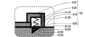
- FIG. 10 is a side view showing the first support device 5R in the first shaking state.
- FIG. 10 is a diagram corresponding to FIG. 3 in the first embodiment.
- FIG. 11 is an enlarged view of a portion C in FIG.
- FIG. 11 is a diagram corresponding to FIG. 4 in the first embodiment.
- the first holding member 54R is fixed to one end of the horizontal connection portion 322R of the first support fitting 32R.
- the first holding member 54R is a bottomed cylindrical member.
- the first holding member 54R is fixed to the horizontal connection portion 322R with the opening facing downward.
- the first elastic deformation member 53R is a coil spring.
- the first elastic deformation member 53R is accommodated in the first holding member 54R.
- One end of the first elastic deformation member 53R is fixed to the bottom of the bottomed cylindrical inner side of the first holding member 54R.
- a first fitting member 41R is fixed to the other end of the first elastic deformation member 53R.
- the first fitting member 41R has the same shape and mounting direction as in the first embodiment.
- the first fitting member 41R includes a protrusion vertical surface portion 411R and a protrusion inclined surface portion 412R, and is attached with the tip formed from the protrusion vertical surface portion 411R and the protrusion inclined surface portion 412R facing downward.
- the first elastic deformation member 53R attaches the first fitting member 41R to the upper surface portion 421R of the first receiving member 42R.
- the first elastic deformation member 53R is a leaf spring.
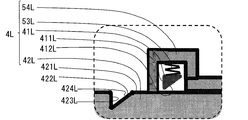
- FIG. 12 is a side view showing the second support device 5L in the first shaking state.
- FIG. 12 is a diagram corresponding to FIG. 5 in the first embodiment.
- FIG. 13 is an enlarged view of a portion D in FIG.
- FIG. 13 is a diagram corresponding to FIG. 6 in the first embodiment.
- the second holding member 54L is fixed to one end of the horizontal connection portion 322L of the second support fitting 32L.
- the second holding member 54L is a bottomed cylindrical member.
- the second holding member 54L is fixed to the horizontal connection portion 322L with the opening facing downward.
- the second elastic deformation member 53L is a coil spring.
- the second elastic deformation member 53L is accommodated in the second holding member 54L.
- One end of the second elastic deformation member 53L is fixed to the bottom of the bottomed cylindrical inner side of the second holding member 54L.
- the second fitting member 41L is fixed to the other end of the second elastic deformation member 53L.
- the second fitting member 41L is the same in shape and mounting direction as in the first embodiment.
- the second fitting member 41L includes a protrusion vertical surface portion 411L and a protrusion inclined surface portion 412L, and is attached with the tip formed from the protrusion vertical surface portion 411L and the protrusion inclined surface portion 412L facing downward.
- the second elastic deformation member 53L attaches the second fitting member 41L to the upper surface portion 421L of the second receiving member 42L.
- the conditions and action in the switching operation between the second holding state and the second released state of the second support device 5L are the same as those in the first embodiment in which the second elastic deformation member 53L is a leaf spring.
- FIG. 14 is a side view showing the first support device 5R of FIG. 10 in the second shaking state.
- FIG. 15 is a side view showing the second support device 5L of FIG. 12 in the second shaking state.
- the conditions and action in the switching operation between the first holding state and the first release state of the first support device 5R in the second shaking state are the same as in the first embodiment in which the first elastic deformation member 53R is a leaf spring.
- the conditions and actions in the switching operation between the second holding state and the second released state of the second support device 5L in the second shaking state are the same as in the first embodiment in which the second elastic deformation member 53L is a leaf spring. It is.
- the first elastic deformation member 53R and the second elastic deformation member 53L are formed as coil springs. Therefore, the operation direction of the first fitting member 41R and the second fitting member 41L can be set to the vertical direction with respect to the upper surface portions 421R and 421L. Accordingly, the lengths of the first support device 5R and the second support device 5L in the horizontal connection portions 322R and 322L, that is, in the horizontal direction can be shortened. In addition, since the coil spring has a longer spring stroke than the leaf spring, the first elastic deformation member 53R and the second elastic deformation member 53L are optimal for switching the state of the first support device 5R and the second support device 5L.
- Spring characteristics For example, the first elastic deformation member 53R and the second elastic deformation member 53L expand and contract more flexibly with respect to the displacement than the first elastic deformation member 43R and the second elastic deformation member 43L configured by leaf springs in the first embodiment. Spring characteristics.
- Embodiment 3 The third embodiment of the present invention is different from the first embodiment in the structure for holding the first support device 6R and the second support device 6L.
- the first support device 4R and the second support device 4L are in the holding state by the fitting of the members, whereas in the third embodiment, the holding state is in the attracting action between the magnets.
- the points other than the parts that change with respect to the change are the same as in the first embodiment.
- the same reference numerals are used for the same members as those in the first embodiment.
- FIG. 16 is a side view showing the first support device 6R in the first shaking state.
- FIG. 4 is a diagram corresponding to FIG. 3 in the first embodiment.
- the first support device 6R includes a first magnet device 64R, a first receiving member 62R, and a first holding member 63R.
- the first receiving member 62R is a plate-like member fixed on the first fixing portion 12R.
- the horizontal connection portion 322R of the first support fitting 32R is slidably mounted on the upper surface portion of the first receiving member 62R.
- the first holding member 63R is a rod-like member having one end fixed to the horizontal connection part 322R of the first support fitting 32R and extending in the horizontal direction away from the first support fitting 32R. At the other end of the first holding member 63R, a short right-angled portion that is bent downward at a right angle is formed.
- the first magnet device 64R includes a first fixed portion side magnet 65R and a first truss end portion side magnet 66R.
- the first fixed portion side magnet 65R is fixed to the upper surface portion of the first receiving member 62R.
- the first truss end portion side magnet 66R is fixed to a right angle portion formed at the other end portion of the first holding member 63R. Therefore, the first truss end portion side magnet 66R moves as the first truss end portion 31R moves.
- the determination of the mounting position of the first fixed portion side magnet 65R in the first receiving member 62R is as follows. First, the truss 3 is installed with the first gap 13R provided between the vertical connection portion 321R of the first support fitting 32R and the first fixing surface 121R of the first fixing portion 12R. The size of the first gap 13R is such that the vertical connection portion 321R and the first fixed surface 121R do not contact even in the second shaking state. In this state, the first fixed portion side magnet 65R is fixed on the first receiving member 62R at a position in contact with the first truss end portion side magnet 66R fixed to the first holding member 63R. That is, when the truss 3 is installed, the first truss end magnet 66R is attracted to the first fixed magnet 65R, and the first support device 6R is in the first holding state.
- the conditions and actions related to the switching operation between the first holding state and the first release state in the first support device 6R are the same as in the case of the first support device 4R in the first embodiment.
- FIG. 17 is a side view showing the second support device 6L in the first shaking state.
- FIG. 6 is a diagram corresponding to FIG. 5 in the first embodiment.
- the second support device 6L includes a second magnet device 64L and a second receiving member 62L.
- the second receiving member 62L is a plate-like member fixed on the second fixing portion 12L.
- the horizontal connection portion 322L of the second support fitting 32L is slidably mounted on the upper surface portion of the second receiving member 62L.
- the second magnet device 64L includes a second fixed portion side magnet 65L and a second truss end portion side magnet 66L.
- the second fixed portion side magnet 65L is fixed to the upper surface portion of the second receiving member 62L.
- the second truss end portion side magnet 66L is fixed to the horizontal connection portion 322L. Therefore, the second truss end portion side magnet 66 ⁇ / b> L moves with the movement of the truss 3.
- the determination of the attachment position of the second stationary member side magnet 65L in the second receiving member 62L is as follows. First, when the truss 3 is installed, the truss 3 is installed with a second gap 13L provided between the vertical connection portion 321L of the second support fitting 32L and the second fixing surface 121L of the second fixing portion 12L. .
- the size of the second gap 13L is such that the vertical connection portion 321L and the second fixed surface 121L are in contact with each other in the second shaking state.
- the second gap 13L disappears, that is, when the vertical connection portion 321L contacts the first fixing surface 121R, the second truss end side magnet 66L comes into contact with the second fixing portion side. Magnet 65L is fixed.
- the second fixed portion side magnet 65L and the second truss end portion side magnet 66L are not in contact with each other.
- the second support device 6L is in the second released state.
- the attractive force between the second fixed portion side magnet 65L and the second truss end portion side magnet 66L of the second support device 6L is the friction force when the first truss end portion 31R slides on the first receiving member 62R.
- the horizontal load determined from both the horizontal inertia force of the truss 3 when the vibration occurs, and the first fixed portion side magnet 65R and the first truss end portion side magnet 66R of the first support device 6R. It is weaker than the adsorption power between.
- the attractive force between the first fixed portion side magnet 65R and the first truss end portion side magnet 66R of the first support device 6R is the friction when the second truss end portion 31L slides on the second receiving member 62L. It is stronger than the horizontal load determined from both the force and the horizontal inertial force of the truss 3 when the vibration occurs, and is weaker than the compressive strength load of the truss 3.
- the conditions and actions relating to the switching operation between the second holding state and the second release state are the same as in the case of the second support device 4L in the first embodiment.
- FIG. 18 is a side view showing the first support device 6R of FIG. 16 in the second shaking state.
- FIG. 18 corresponds to FIG. 7 in the first embodiment.
- FIG. 19 is a side view showing the second support device 6L of FIG. 17 in the second shaking state.
- FIG. 19 corresponds to FIG. 8 in the first embodiment.
- the first support device 6R includes a first fixed portion side magnet 65R and a first truss end portion side magnet 66R.
- the second support device 6L includes a second fixed portion side magnet 65L and a second truss end portion side magnet 66L.
- the first holding device 6R can be switched between the first holding state and the first releasing state by using the magnet, and the second holding device 6L can be switched between the second holding state and the second releasing state. The state can be switched. Further, since there is no need to process the grooves in each of the first receiving member 62R and the second receiving member 62L, the manufacturing work for each of the first support device 6R and the second support device 6L can be reduced. Can do.
- first support device and the second support device may be configured by combining the above-described embodiments.
- the first support device may have a fitting structure
- the second support device may have a magnetic adsorption structure
- the first support device may have a magnetic adsorption structure
- the second support device may have a fitting structure. Even in this case, the same effect as in the first embodiment can be obtained.
- first support fitting 32R and the second support fitting 32L are provided as separate members on the first truss end 31R and the second truss end 31L, respectively.
- the first support fitting 32R and the second support fitting 32L may be integrally formed with the first truss end portion 31R and the second truss end portion 31L, respectively. Even in this case, the same effect as in the first embodiment can be obtained.
- the present invention is applied to an escalator 2 that is a passenger conveyor provided between an upper floor 10 and a lower floor 11 having different floor heights.
- an escalator 2 that is a passenger conveyor provided between an upper floor 10 and a lower floor 11 having different floor heights.
- a moving walkway that is a passenger conveyor provided between the floors having the same height.
Landscapes
- Escalators And Moving Walkways (AREA)
Abstract
本発明に係るエスカレータは、第1トラス端部及び第2トラス端部を有するトラス、第1トラス端部を支持する第1支持装置、及び第2トラス端部を支持する第2支持装置を備えている。第1支持装置は、第1保持状態と、第1解放状態との間で切り替え可能である。また、第2支持装置は、第2保持状態と、第2解放状態との間で切り替え可能である。エスカレータでは、第1支持装置の第1保持状態、及び第2支持装置の第2保持状態の少なくとも何れか一方の状態が生じている。
Description
本発明は、トラスを備える乗客コンベアに関するものである。
乗客コンベアには、建物の上階と下階との間に設置されているエスカレータがある。特許文献1に記載されているエスカレータのトラスの一端は、固定ピンにより建物に固定されている。また、エスカレータのトラスの他端は、建物に対し摺動可能に支持されている。すなわち、上記エスカレータのトラスの一方の支持点は、固定された支持構造である。また、他方の支持点は、摺動可能な支持構造である。
地震が発生すると建物が揺れ、一方の支持点と他方の支持点との間に相対移動が起こる。この際、一方及び他方の支持点間の変位量が一定量以下の場合では、トラスの他端が建物に対し摺動して、トラスに過大な圧縮力はかからない。また、一方及び他方の支持点間の変位量が一定以上の場合では、トラスと建物とを固定している固定ピンが破断する。それにより、トラスの第1トラス端部が建物に対して移動可能となり、トラスに過大な圧縮力がかからなくなっている。
しかしながら、特許文献1に記載されている従来のエスカレータでは、大きな揺れで固定ピンが破断する。固定点を失ったトラスは、揺れにより建物に対し移動する。すなわち、地震によりトラスがずれてしまっていた。したがって、トラスをクレーンで吊り上げ、設置時の位置に戻すという、復旧作業が必要であった。
本発明は、上記の課題を解決するためにされたものである。具体的には、大きな揺れがあっても、復旧作業を必要としない乗客コンベアを提供することを目的としている。
本発明に係る乗客コンベアは、建物における第1固定部と第2固定部との間に設置され、第1トラス端部及び第2トラス端部を有するトラス、第1固定部に設けられ、第1トラス端部を支持する第1支持装置、及び第2固定部に設けられ、第2トラス端部を支持する第2支持装置、を備え、第1支持装置は、第1固定部と第1トラス端部とを、相対移動させない第1保持状態と、水平方向に相対移動可能にさせる第1解放状態との間で切り替え可能であり、第2支持装置は、第2固定部と第2トラス端部とを、相対移動させない第2保持状態と、水平方向に相対移動可能にさせる第2解放状態との間で切り替え可能であり、第1支持装置の第1保持状態、及び第2支持装置の第2保持状態の少なくとも何れか一方の状態が生じている乗客コンベアである。
本発明に係る乗客コンベアでは、第1支持装置の第1保持状態、及び第2支持装置の第2保持状態の少なくとも何れか一方の状態が生じている。すなわち、揺れに関わらず常に、第1支持装置及び第2支持装置の少なくとも何れか一方は、トラスを建物に保持している。したがって、本発明に係る乗客コンベアでは、建物が揺れた後の復旧作業は必要ではない。
実施の形態1.
本発明の実施の形態1に係る乗客コンベアであるエスカレータを説明する。
本発明の実施の形態1に係る乗客コンベアであるエスカレータを説明する。
図1は、エスカレータ2が設置された建物1の概略図である。この例では、エスカレータ2は、建物1における、3階の上階床10と、2階の下階床11とに渡って設けられている。なお、揺れの発生時に建物が傾く方向について、図1における右方向を正方向とする。
図2は、図1のエスカレータ2の設置状態を示した模式図である。上階床10には、第1固定部12Rが設けられている。下階床11には、第2固定部12Lが設けられている。第1固定部12Rの位置は、第2固定部12Lの位置よりも高い位置で、かつ、第2固定部12Lの位置に対して水平方向へ離れた位置となっている。
建物1が揺れていない状態では、第1固定部12Rと第2固定部12Lとの間の水平距離が、後述する基準距離よりも大きくなっている。地震により建物1が揺れると、第1固定部12Rと第2固定部12Lとが相対移動する。そのため、第1固定部12Rと第2固定部12Lとの間の水平距離が変化する。この水平距離の変化量は、地震の規模、及び建物1の構造により変動する。本明細書では、建物1が揺れて第1固定部12Rと第2固定部12Lとの間の水平距離が変化する場合、当該水平距離の上限値と下限値とがいずれも基準距離以上の範囲に収まる小さな揺れの状態を第1揺れ状態とし、当該水平距離の上限値が基準距離よりも大きくなり当該水平距離の下限値が基準距離よりも小さくなるように当該水平距離の変化が大きくなる揺れの状態を第2揺れ状態とする。
エスカレータ2は、トラス3と、トラス3を支持する第1支持装置4R及び第2支持装置4Lとを備えている。
トラス3は、鋼材の梁が複数組み合わされて構成されている。また、トラス3は、トラス3の一方端に位置する第1トラス端部31Rと、トラス3の他方端に位置する第2トラス端部31Lとを有している。
第1トラス端部31Rは、第1支持金具32Rを含んでいる。建物1の第1固定部12Rには、トラス3の第1トラス端部31Rの第1端面311Rが対向する第1固定面121Rが設けられている。
第2トラス端部31Lは、第2支持金具32Lを含んでいる。建物1の第2固定部12Lには、トラス3の第2トラス端部31Lの第2端面311Lが対向する第2固定面121Lが設けられている。
第1支持装置4Rは、第1固定部12Rに設けられている。また、第1支持装置4Rは、トラス3の第1トラス端部31Rを支持している。これにより、トラス3の第1トラス端部31Rは、第1支持装置4Rを介して第1固定部12Rに支持されている。
第2支持装置4Lは、第2固定部12Lに設けられている。また、第2支持装置4Lは、トラス3の第2トラス端部31Lを支持している。これにより、トラス3の第2トラス端部31Lは、第2支持装置4Lを介して第2固定部12Lに支持されている。
図3は、図2の第1支持装置4Rを示す側面図である。また、図4は、図3におけるA部の拡大図である。
第1支持金具32Rは、図3に示すように、断面L字形状の山形鋼である。第1支持金具32Rは、垂直接続部321Rと、水平接続部322Rとを含んでいる。第1支持金具32Rの断面形状は、垂直接続部321R及び水平接続部322RによってL字形状になっている。
垂直接続部321Rは、第1トラス端部31Rの第1端面311Rに固定されている。水平接続部322Rは、垂直接続部321Rの上端部から第1固定部12Rに向かって延びている。
第1支持装置4Rは、第1嵌合部材41R、第1受け部材42R、及び第1弾性変形部材43Rを有している。
第1受け部材42Rは、第1固定部12Rに固定されている。また、第1受け部材42Rは、上面部421Rを有する板状部材である。第1受け部材42Rの上面部421Rには、第1支持金具32Rの水平接続部322Rが摺動自在に載せられている。第1支持金具32Rの垂直接続部321Rと、第1固定部12Rの第1固定面121Rとの間には、水平方向において第1隙間13Rが設けられている。第1隙間13Rの大きさは、第2揺れ状態の時においても、垂直接続部321Rと第1端面311Rとが接触しない十分な大きさとされている。
第1受け部材42Rの上面部421Rには、第1嵌合部材41Rが嵌合する第1溝部422Rが形成されている。トラス3の側面視方向に沿って見た第1溝部422Rの断面形状は、溝垂直面部423Rと溝傾斜面部424Rとを含む直角三角形である。溝垂直面部423Rは、上面部421Rに対して垂直になっている。溝傾斜面部424Rは、上面部421Rに対して傾斜している。溝垂直面部423Rは、溝傾斜面部424Rに対し、第1トラス端部31R側に位置している。溝垂直面部423Rと溝傾斜面部424Rとの間の距離である第1溝部422Rの幅は、第1溝部422Rの上方の開口部で広く、下方ほど狭くなっている。
第1嵌合部材41Rは、突起垂直面部411Rと突起傾斜面部412Rとを含んでいる。エスカレータ2の側面視における第1嵌合部材41Rの断面は、直角三角形である。突起垂直面部411Rは、突起傾斜面部412Rに対し、第1トラス端部31R側に位置している。第1嵌合部材41Rが第1溝部422Rに嵌合している状態では、突起垂直面部411Rが第1受け部材42Rの上面部421Rに対し垂直になり、突起傾斜面部412Rが第1受け部材42Rの上面部421Rに対し傾斜する。
第1弾性変形部材43Rは、板ばねである。第1弾性変形部材43Rの一方端は、第1支持金具32Rの水平接続部322Rに固定されている。第1弾性変形部材43Rの他方端には、第1弾性変形部材43Rとは別体で形成された第1嵌合部材41Rが設けられている。なお、第1弾性変形部材43Rと第1嵌合部材41Rとは、一体に形成されていてもよい。
第1嵌合部材41Rと第1溝部422Rとは、突起垂直面部411Rと溝垂直面部423Rとが接し、かつ突起傾斜面部412Rと溝傾斜面部424Rとが接した状態で嵌合する。第1嵌合部材41Rが第1溝部422Rに嵌合している状態では、第1隙間13Rが生じている。第1嵌合部材41Rと第1受け部材42Rとは、第1弾性変形部材43Rが弾性変形していない状態において嵌合する。第1弾性変形部材43Rは、第1溝部422Rから外れる方向へ第1嵌合部材41Rが溝傾斜面部424Rに沿って滑り上がることにより弾性変形する。これにより、第1弾性変形部材43Rは、第1嵌合部材41Rが第1溝部422Rから外れる方向への力に逆らう弾性復元力を発生する。即ち、第1弾性変形部材43Rは、弾性復元力によって第1嵌合部材41Rが第1溝部422Rに嵌合するように第1嵌合部材41Rを付勢する。第1嵌合部材41Rと第1溝部422Rとの嵌合が外れている場合、第1弾性変形部材43Rは、第1嵌合部材41Rを上面部421Rに押し付ける方向へ第1嵌合部材41Rを付勢する。
第1嵌合部材41Rと第1溝部422Rとが嵌合することで、第1支持装置4Rは第1固定部12Rと第1トラス端部31Rとを、相対移動させないように保持する。この状態が第1保持状態である。また、第1嵌合部材41Rと第1溝部422Rとが外れることで、第1支持装置4Rは第1固定部12Rと第1トラス端部31Rとを、水平方向に相対移動可能にさせるよう解放する。この状態が第1解放状態である。第1支持装置4Rは、第1保持状態から第1解放状態への切り替え、及び第1解放状態から第1保持状態への切り替えの両方の切り替えが可能になっている。
図5は、図2の第2支持装置4Lを示す側面図である。また、図6は、図5におけるB部の拡大図である。
第2支持金具32Lは、図5に示すように、断面L字形状の山形鋼である。第2支持金具32Lは、垂直接続部321Lと、水平接続部322Lとを含んでいる。第2支持金具32Lの断面形状は、垂直接続部321L及び水平接続部322LによってL字形状になっている。
垂直接続部321Lは、第2トラス端部31Lの第2端面311Lに固定されている。水平接続部322Lは、垂直接続部321Lの上端部から第2固定部12Lに向かって延びている。
第2支持装置4Lは、第2嵌合部材41L、第2受け部材42L、及び第2弾性変形部材43Lを有している。
第2受け部材42Lは、第2固定部12Lに固定されている。また、第2受け部材42Lは、上面部421Lを有する板状部材である。第2受け部材42Lの上面部421Lには、第2支持金具32Lの水平接続部322Lが摺動自在に載せられている。第2支持金具32Lの垂直接続部321Lと、第2固定部12Lの第2固定面121Lとの間には、水平方向において第2隙間13Lが設けられている。第2隙間13Lの大きさは、第2揺れ状態の時において、垂直接続部321Lと第2端面311Lとが接触する大きさとされている。
第2受け部材42Lの上面部421Lには、第2嵌合部材41Lが嵌合する第2溝部422Lが形成されている。トラス3の側面視方向に沿って見た第2溝部422Lの断面形状は、溝垂直面部423Lと溝傾斜面部424Lとを含む直角三角形である。溝垂直面部423Lは、上面部421Lに対して垂直になっている。溝傾斜面部424Lは、上面部421Lに対して傾斜している。溝傾斜面部424Lは、溝垂直面部423Lに対し、第2トラス端部31L側に位置している。溝垂直面部423Lと溝傾斜面部424Lとの間の距離である第2溝部422Lの幅は、第2溝部422Lの上方の開口部で広く、下方ほど狭くなっている。
第2嵌合部材41Lは、突起垂直面部411Lと突起傾斜面部412Lとを含んでいる。エスカレータ2の側面視における第2嵌合部材41Lの断面は、直角三角形である。突起傾斜面部412Lは、突起垂直面部411Lに対し、第2トラス端部31L側に位置している。第2嵌合部材41Lが第2溝部422Lに嵌合している状態では、突起垂直面部411Lが第2受け部材42Lの上面部421Lに対し垂直になり、突起傾斜面部412Lが第2受け部材42Lの上面部421Lに対し傾斜する。
第2弾性変形部材43Lは、板ばねである。第2弾性変形部材43Lの一方端は、第2支持金具32Lの水平接続部322Lに固定されている。第2弾性変形部材43Lの他方端には、第2弾性変形部材43Lとは別体で形成された第2嵌合部材41Lが設けられている。なお、第2弾性変形部材43Lと第2嵌合部材41Lとは、一体に形成されていてもよい。
第2嵌合部材41Lと第2溝部422Lとは、突起垂直面部411Lと溝垂直面部423Lとが接し、かつ突起傾斜面部412Lと溝傾斜面部424Lとが接した状態で嵌合する。第2嵌合部材41Lと第2受け部材42Lとは、第2弾性変形部材43Lが弾性変形していない状態において嵌合する。第2弾性変形部材43Lは、第2溝部422Lから外れる方向へ第2嵌合部材41Lが溝傾斜面部424Lに沿って滑り上がることにより弾性変形する。これにより、第2弾性変形部材43Lは、第2嵌合部材41Lが第2溝部422Lから外れる方向への力に逆らう弾性復元力を発生する。即ち、第2弾性変形部材43Lは、弾性復元力によって第2嵌合部材41Lが第2溝部422Lに嵌合するように第2嵌合部材41Lを付勢する。第2嵌合部材41Lと第2溝部422Lとの嵌合が外れている場合、第2弾性変形部材43Lは、第2嵌合部材41Lを上面部421Lに押し付ける方向へ第2嵌合部材41Lを付勢する。
第2嵌合部材41Lが第2溝部422Lに嵌合している状態では、第2トラス端部31Lが第2固定部12Lと接触している。トラス3の設置時には、第2嵌合部材41Lが第2溝部422Lから外れて、第2トラス端部31Lと第2固定部12Lとの間に第2隙間13Lが生じている。
第2嵌合部材41Lと第2溝部422Lとが嵌合することで、第2支持装置4Lは第2固定部12Lと第2トラス端部31Lとを、相対移動させないように保持する。この状態が第2保持状態である。また、第2嵌合部材41Lと第2溝部422Lとが外れることで、第2支持装置4Lは第2固定部12Lと第2トラス端部31Lとを、水平方向に相対移動可能にさせるよう解放する。この状態が第2解放状態である。第2支持装置4Lは、第2保持状態から第2解放状態への切り替え、及び第2解放状態から第2保持状態への切り替えの両方の切り替えが可能になっている。
トラス3の設置時、及び第1揺れ状態において、第2嵌合部材41Lは第2溝部422Lから外れている。すなわち、トラス3の設置時、及び第1揺れ状態において、第2支持装置4Lは、トラス3の第2トラス端部31Lが第2固定部12Lに対して摺動可能な第2解放状態にある。したがって、第1揺れ状態の場合、第2支持金具32Lの水平接続部322Lは、第2受け部材42Lの上面部421L上を摺動する。
なお、第1固定部12Rと第2固定部12Lとの間の基準距離とは、第1嵌合部材41Rと第1溝部422Rとが嵌合し、かつ第2嵌合部材41Lと第2溝部422Lとが嵌合した状態における、第1固定部12Rと第2固定部12Lとの間の水平距離である。言い換えれば、基準距離は、トラス3の設置時における、第1固定部12Rと第2固定部12Lとの間の水平距離から、トラス3の設置時に設けられている第2隙間13Lの間隔を引いた距離である。
図7は、図2の第1固定部12Rと第2固定部12Lとの間の水平距離が基準距離よりも小さくなったときの第1支持装置4Rを示す側面図である。また、図8は、図2の第1固定部12Rと第2固定部12Lとの間の水平距離が基準距離よりも小さくなったときの第2支持装置4Lを示す側面図である。設置時及び第1揺れ状態においては、第1支持装置4Rは第1保持状態であり、第2支持装置4Lは第2解放状態である。そのため、第2トラス端部31Lは第2固定部12Lに対し、相対移動可能である。建物1の揺れに伴い、建物1に保持された第1トラス端部31Rも建物1と共に揺れる。そのため、建物1に保持されていない第2トラス端部31Lは、揺れながら第2固定部12Lに接近する。そして、ついには第2トラス端部31Lが、第2固定部12Lに接触する。図8に示すように、第2トラス端部31Lが、第2固定部12Lに接触した時点で、第2嵌合部材41Lは、第2受け部材42Lの第2溝部422Lと嵌合する。すなわち、第2支持装置4Lが第2保持状態になる。第2支持装置4Lが第2保持状態になると、第2トラス端部31Lと第2固定部12Lとは相対移動できなくなる。
第2トラス端部31Lが第2固定部12Lと接触し、第2支持装置4Lが第2保持状態になった後も、引き続く揺れにより、第2トラス端部31Lと第2固定部12Lとは、さらに接近する方向に、相対移動しようとする。そのため、第2嵌合部材41Lの突起垂直面部411Lと第2受け部材42Lの溝垂直面部423Lとの間に、互いに接近させる方向に水平荷重が働く。その結果、突起垂直面部411Lが溝垂直面部423Lを押す。突起垂直面部411Lと溝垂直面部423Lとは垂直面同士であるから、突起垂直面部411Lと溝垂直面部423Lとの面同士の滑りは発生しない。したがって、突起垂直面部411Lが溝垂直面部423Lを押す水平荷重は、トラス3に作用する。すなわち、建物1が揺れる動きは、一体的に動く第2トラス端部31Lと第2固定部12Lとを介して、第2トラス端部31Lに水平荷重として作用する。その結果、トラス3が押される。
トラス3が押されると、第1支持装置4Rにおいて、第1嵌合部材41Rの突起傾斜面部412Rと第1受け部材42Rの溝傾斜面部424Rとの間に、互いに接近させる方向に水平荷重が作用する。突起傾斜面部412Rと溝傾斜面部424Rとは、傾斜面同士である。そのため、突起傾斜面部412Rと溝傾斜面部424Rとの間に作用する水平荷重により、突起傾斜面部412Rは溝傾斜面部424Rを滑り上がるように相対移動する。その結果、第1嵌合部材41Rが第1受け部材42Rの第1溝部422Rから外れる。したがって、第1トラス端部31Rは、第1固定部12Rに対し相対移動できるようになる。
突起垂直面部411Lと溝垂直面部423Lとの間、つまり垂直面同士の間において、互いに接近させる方向に水平荷重が働いても、第2嵌合部材41Lと第2溝部422Lとの嵌合は外れない。第2支持装置4Lは、第2保持状態のままである。また、突起傾斜面部412Rと溝傾斜面部424Rとの間、つまり傾斜面同士の間において、互いに接近させる方向に水平荷重が働いた時には、第1嵌合部材41Rと第1溝部422Rとの嵌合が外れる。その結果、第1支持装置4Rは、第1保持状態から第1解放状態になる。
第1揺れ状態より揺れが大きい第2揺れ状態では、建物1が揺れる過程において、第2支持装置4Lは、第2解放状態から第2保持状態に切り替わる。また、第2支持装置4Lが、第2解放状態から第2保持状態に切り替わると同時に、第1支持装置4Rが、第1保持状態から第1解放状態に切り替わる。すなわち、第2揺れ状態において、トラス3を保持する装置が、第2支持装置4Lから第1支持装置4Rに切り替わる。
第1固定部12Rと第2固定部12Lとの間の水平距離の変動に対する、第1支持装置4R及び第2支持装置4Lは、以下のように作動する。第1固定部12Rと第2固定部12Lとの間の水平距離が基準距離である時は、第1支持装置4Rが第1保持状態であるとともに、第2支持装置4Lが第2保持状態である。また、第1固定部12Rと第2固定部12Lとの間の水平距離が、基準距離より大きい時は、第1支持装置4Rが第1保持状態であるとともに、第2支持装置4Lが第2解放状態である。また、第1固定部12Rと第2固定部12Lとの間の水平距離が、基準距離より小さい時は、第1支持装置4Rが第1解放状態であるとともに、第2支持装置4Lが第2保持状態である。
第1支持装置4Rが第1保持状態から第1解放状態に切り替わる時の水平荷重は、以下のようにされている。第1支持装置4Rが第1解放状態に切り替わる水平荷重は、建物1が揺れている時にトラス3に作用するトラス3の水平方向の慣性力、及びトラス3の第2トラス端部31Lと第2支持装置4Lとの間の摩擦力の両方によって決定される水平荷重よりも大きく、かつトラス3の圧縮強度未満とされている。なお、第1支持装置4Rが第1保持状態から第1解放状態に切り替わる時の水平荷重は、トラス3に圧縮荷重として作用する。
また、第2支持装置4Lが第2保持状態から第2解放状態に切り替わる時の水平荷重は、以下のようにされている。第2支持装置4Lが第2解放状態に切り替わる水平荷重は、建物1が揺れている時にトラス3に作用するトラス3の水平方向の慣性力、及び第1トラス端部31Rと第1支持装置4Rとの間の摩擦力の両方によって決定される水平荷重よりも大きく、かつ第1支持装置4Rの破壊強度未満とされている。なお、第2支持装置4Lが第2保持状態から第2解放状態に切り替わる時の水平荷重は、トラス3に引張荷重として作用する。
次に、地震発生時における建物1の揺れと、それに対する第1支持装置4R及び第2支持装置4Lのそれぞれの作動との関係について説明する。図9は、建物1の揺れと、第1支持装置4R及び第2支持装置4Lのそれぞれの作動との関係を示す概念図である。なお、図9(A)から図9(H)においては、容易な理解のために、各図中で第2固定部12Lの位置を固定して記載している。
図9(A)は、トラス3の設置時の状態を示している。トラス3の設置時において、第1支持装置4Rは第1保持状態であり、第2支持装置4Lは第2解放状態である。
図9(B)は、第1揺れ状態において建物1が正方向に傾いたときの第1支持装置4R及び第2支持装置4Lを示している。また、図9(C)は、第1揺れ状態において建物1が負方向に傾いたときの第1支持装置4R及び第2支持装置4Lを示している。第1揺れ状態において建物1が正方向に傾くと、第1固定部12Rと第2固定部12Lとの間の水平距離は、図9(B)に示すように、トラス3の設置時より広がる。これにより、第1支持装置4Rが第1保持状態を保ち、第2支持装置4Lが第2解放状態を保ったまま、トラス3は、第2固定部12Lに対し正方向に移動する。その際、第2トラス端部31Lは第2受け部材42Lに対して摺動する。その結果、第2支持金具32Lの垂直接続部321Lと第2固定部12Lの第2固定面121Lとの間の第2隙間13Lが広くなる。
その後、建物1が負方向に傾くと、図9(C)に示すように、第1支持装置4Rが第1保持状態を保ち、第2支持装置4Lが第2解放状態を保ったまま、トラス3が負方向に移動する。この時、第2トラス端部31Lは第2受け部材42Lに対して摺動して、第2隙間13Lが狭くなる。すなわち、第1固定部12Rと第2固定部12Lとの間の水平距離は、トラス3の設置時より狭くなっている。
すなわち、第1揺れ状態においては、第1支持装置4Rが第1保持状態、第2支持装置4Lが第2解放状態のまま、図9(B)及び図9(C)の状態を繰り返す。そして、最終的に揺れが収束する。
図9(D)から図9(H)は、第2揺れ状態における建物1の揺れと、第1支持装置4R及び第2支持装置4Lのそれぞれの状態との関係を示している。建物1の揺れの状態が第2揺れ状態であるときには、第1揺れ状態のときよりも建物1が大きく揺れる。図9(D)に示すように、第2揺れ状態において建物1が正方向に傾くと、第1固定部12Rと第2固定部12Lとの間の水平距離は、トラス3の設置時より広がる。この時、第1支持装置4Rが第1保持状態を保ち、第2支持装置4Lが第2解放状態を保ったまま、トラス3が正方向に移動する。そのため、第2トラス端部31L側は第2受け部材42Lに対して摺動する。その結果、第2支持金具32Lの垂直接続部321Lと第2固定面121Lとの間の第2隙間13Lは、第1揺れ状態である図9(B)の時より広がる。垂直接続部321Lがかかる第2受け部材42Lの長さは、揺れが最大の時にもトラス3が脱落しない十分な長さとされている。そのため、垂直接続部321Lが第2受け部材42Lにかかるかかり代は十分確保されており、揺れが起きても、トラス3は常に建物1に支持されている。
図9(E)は、図9(D)の直後の状態を示している。建物1が負方向に傾くことで、第1固定部12Rと第2固定部12Lとの間の水平距離は狭くなる。この時、第1支持装置4Rは第1保持状態を保ち、第2支持装置4Lは第2解放状態を保ったまま、トラス3が負方向に移動する。そのため、第2トラス端部31Lは第2受け部材42Lに対して摺動する。第2支持金具32Lの垂直接続部321Lと第2固定面121Lとの間の第2隙間13Lはなくなり、垂直接続部321Lと第2固定面121Lとが接触する。すなわち、第1固定部12Rと第2固定部12Lとの間の水平距離が基準距離となる。この時に、第2支持装置4Lは第2解放状態から第2保持状態に切り替わる。すなわち、第1支持装置4Rが第1保持状態のまま、第2支持装置4Lが第2保持状態になる。それにより、トラス3には、揺れによる第2固定部12Lの動きが伝わるようになる。その結果、トラス3には、第2支持装置4Lを介して、第2固定部12Lから水平荷重が作用する。そのため、トラス3を介して、第1支持装置4Rに水平荷重がかかり始める。
図9(F)は、図9(E)の直後の状態を示している。建物1がさらに負方向に傾くにつれ、トラス3に作用する水平荷重は、図9(E)の状態よりさらに大きくなる。第1支持装置4Rが第1保持状態の間は、トラス3に作用する水平荷重は、トラス3に圧縮荷重として作用する。そして、トラス3に作用する水平荷重が、第1支持装置4Rの第1解放状態への切り替え荷重に到達すると、トラス3の圧縮強度荷重に到達する前に、第1支持装置4Rが第1保持状態から第1解放状態に切り替わる。その後、引き続く揺れにより、建物1がさらに負方向に傾くと、トラス3が第1固定部12Rに対しさらに移動し、第1トラス端部31Rが第1受け部材42Rに対して摺動する。そのため、第1固定部12Rと第2固定部12Lとの間の水平距離が図9(E)の状態よりさらに狭くなり、垂直接続部321Rと第1固定面121Rとの間の第1隙間13Rが狭くなる。第1支持装置4Rが第1解放状態に切り替わることにより、第1トラス端部31Rが第1固定部12Rに対して摺動するため、トラス3に作用していた圧縮荷重は激減する。
図9(G)は、図9(F)の直後の状態を示している。建物1は、図9(F)に対し、反対方向に揺れ始めた状態である。建物1が負方向に揺れた後に正方向に揺れ始めると、第1トラス端部31Rが正方向に摺動し、第1隙間13Rが広がる。その後、第1嵌合部材41Rが第1溝部422Rに到達して、第1嵌合部材41Rが第1溝部422Rに嵌合する。すなわち、第1支持装置4Rは、第1解放状態から第1保持状態に切り替わる。
図9(H)は、図9(G)の状態から建物1の揺れが収まった状態を示している。建物1は、図9(G)の状態からさらに正方向に揺れることにより設置状態に戻る。このとき、第1支持装置4Rが保持状態を保ち、第2支持装置4Lが保持状態を保ったまま、トラス3が正方向に移動する。そのため、第2嵌合部材41Lが第2溝部422Lから外れる。すなわち、第1支持装置4Rがトラス3の設置時と同じ第2解放状態に戻る。その結果、第2トラス端部31Lは第2受け部材42Lに対して摺動する。建物1が設置状態に戻ることで、第2隙間13Lが図9(G)の状態より広くなる。すなわち、第1固定部12Rと第2固定部12Lとの間の距離が、図9(G)の状態より広くなる。トラス3の建物1に対する位置、第1支持装置4Rの状態、及び第2支持装置4Lの状態は、設置時の状態に戻る。
本発明の実施の形態1におけるエスカレータ2では、第1支持装置4Rが第1保持状態と第1解放状態との間で切り替え可能であり、第2支持装置4Lが第2保持状態と第2解放状態との間で切り替え可能である。また、建物1が揺れて第1支持装置4R及び第2支持装置4Lのそれぞれの状態が切り替わっても、第1支持装置4Rの第1保持状態及び第2支持装置4Lの第2保持状態の少なくともいずれかの状態がエスカレータ2に生じている。すなわち、第1支持装置4R及び第2支持装置4Lの少なくともいずれか一方が、常にトラス3と建物1とを相対移動しない状態に保持している。したがって、建物1が揺れてトラス3が建物1に対して移動しても、第1固定部12R及び第2固定部12Lの少なくともいずれかに対してはトラス3の位置を保持することができる。このため、建物1が揺れたときに、第1固定部12R及び第2固定部12Lの両方に対するトラス3の位置が同時にずれてしまうことを防止することができる。これにより、建物1が揺れた場合であっても、第1固定部12R及び第2固定部12Lに対するエスカレータ2の位置を元の位置に自動的に戻すことができ、エスカレータ2の復旧作業の必要がなくなる。
また、第1保持状態から第1解放状態への切り替え、及び第2保持状態から第2解放状態への切り替えに必要な水平荷重の大きさは、トラス3の圧縮強度よりも小さい荷重である。したがって、トラス3に圧縮強度以上の水平荷重がかかることを防ぐことができる。その結果、トラス3が破損することを防止することができる。
実施の形態2.
本発明の実施の形態2では、実施の形態1に対し、第1弾性変形部材53R及び第2弾性変形部材53Lがコイルばねである点が異なっている。また、第1弾性変形部材53R及び第2弾性変形部材53Lをそれぞれ保持する第1保持部材54R及び第2保持部材54Lが設けられている点が異なっている。その他の点は、上記実施の形態1と同じである。以下の説明において、実施の形態1と同じ部材には同じ符号を用いる。
本発明の実施の形態2では、実施の形態1に対し、第1弾性変形部材53R及び第2弾性変形部材53Lがコイルばねである点が異なっている。また、第1弾性変形部材53R及び第2弾性変形部材53Lをそれぞれ保持する第1保持部材54R及び第2保持部材54Lが設けられている点が異なっている。その他の点は、上記実施の形態1と同じである。以下の説明において、実施の形態1と同じ部材には同じ符号を用いる。
図10は、第1揺れ状態における第1支持装置5Rを示す側面図である。図10は、実施の形態1における、図3に相当する図である。また、図11は、図10におけるC部の拡大図である。図11は、実施の形態1における、図4に相当する図である。
第1支持金具32Rの水平接続部322Rの一方端には、第1保持部材54Rが固定されている。第1保持部材54Rは有底筒状の部材である。第1保持部材54Rは、開口部を下向きにして水平接続部322Rに固定されている。
第1弾性変形部材53Rは、コイルばねである。第1弾性変形部材53Rは、第1保持部材54Rに収容されている。第1弾性変形部材53Rの一方端は、第1保持部材54Rの有底筒状の内側の底部に固定されている。また、第1弾性変形部材53Rの他方端には、第1嵌合部材41Rが固定されている。なお、第1嵌合部材41Rは、形状及び取付の向きとも、実施の形態1の場合と同じである。第1嵌合部材41Rは、突起垂直面部411Rと突起傾斜面部412Rとを含んでおり、突起垂直面部411Rと突起傾斜面部412Rとから形成されている先細部を下向きにして取り付けられている。
第1弾性変形部材53Rと第1嵌合部材41Rとが、このように取り付けられていることにより、第1弾性変形部材53Rは、第1嵌合部材41Rを第1受け部材42Rの上面部421Rに向けて、上面部421Rに対し垂直に付勢している。第1支持装置5Rの第1保持状態と第1解放状態との切り替え作動に関する条件及び作用は、第1弾性変形部材53Rが板ばねである実施の形態1と同じである。
図12は、第1揺れ状態における第2支持装置5Lを示す側面図である。図12は、実施の形態1における図5に相当する図である。図13は、図12におけるD部の拡大図である。図13は、実施の形態1における、図6に相当する図である。
第2支持金具32Lの水平接続部322Lの一方端には、第2保持部材54Lが固定されている。第2保持部材54Lは有底筒状の部材である。第2保持部材54Lは、開口部を下向きにして、水平接続部322Lに固定されている。
第2弾性変形部材53Lは、コイルばねである。第2弾性変形部材53Lは、第2保持部材54Lに収容されている。第2弾性変形部材53Lの一方端は、第2保持部材54Lの有底筒状の内側の底部に固定されている。また、第2弾性変形部材53Lの他方端には、第2嵌合部材41Lが固定されている。なお、第2嵌合部材41Lは、形状及び取付の向きとも、実施の形態1の場合と同じである。第2嵌合部材41Lは、突起垂直面部411Lと突起傾斜面部412Lとを含んでおり、突起垂直面部411Lと突起傾斜面部412Lとから形成されている先細部を下向きにして取り付けられている。
第2弾性変形部材53Lと第2嵌合部材41Lとが、このように取り付けられていることにより、第2弾性変形部材53Lは、第2嵌合部材41Lを第2受け部材42Lの上面部421Lに向けて、上面部421Lに対し垂直に付勢している。第2支持装置5Lの第2保持状態と第2解放状態との切り替え作動における条件及び作用は、第2弾性変形部材53Lが板ばねである実施の形態1と同じである。
図14は、第2揺れ状態における、図10の第1支持装置5Rを示す側面図である。また、図15は、第2揺れ状態における、図12の第2支持装置5Lを示す側面図である。第2揺れ状態における、第1支持装置5Rの第1保持状態と第1解放状態の切り替え作動における条件及び作用は、第1弾性変形部材53Rが板ばねである実施の形態1と同じである。同様に、第2揺れ状態における、第2支持装置5Lの第2保持状態と第2解放状態の切り替え作動における条件及び作用は、第2弾性変形部材53Lが板ばねである実施の形態1と同じである。
本発明の実施の形態2における、第1弾性変形部材53Rと第2弾性変形部材53Lとは、コイルばねとして形成されている。そのため、第1嵌合部材41R及び第2嵌合部材41Lの作動方向を、上面部421R、421Lに対し、垂直方向にすることができる。それにより、水平接続部322R、322L方向、すなわち水平方向における第1支持装置5R及び第2支持装置5Lの長さを短くすることができる。また、板ばねよりも長いばねストロークにできるコイルばねであるから、第1弾性変形部材53R及び第2弾性変形部材53Lは、第1支持装置5R及び第2支持装置5Lの状態の切り替え作動に最適なばね特性とすることができる。例えば、第1弾性変形部材53R及び第2弾性変形部材53Lは、実施の形態1における、板ばねで構成された第1弾性変形部材43R及び第2弾性変形部材43Lより、変位に対ししなやかに伸縮するばね特性とすることができる。
実施の形態3.
本発明の実施の形態3は、実施の形態1に対し、第1支持装置6R及び第2支持装置6Lを保持状態とするための構造が異なっている。実施の形態1において、第1支持装置4R及び第2支持装置4Lが、部材同士の嵌合によって保持状態としているのに対し、実施の形態3では、磁石同士の吸着作用により保持状態としている。その変更に関して変わる部位以外の点は、実施の形態1と同様である。以下の説明において、実施の形態1と同じ部材には同じ符号を用いる。
本発明の実施の形態3は、実施の形態1に対し、第1支持装置6R及び第2支持装置6Lを保持状態とするための構造が異なっている。実施の形態1において、第1支持装置4R及び第2支持装置4Lが、部材同士の嵌合によって保持状態としているのに対し、実施の形態3では、磁石同士の吸着作用により保持状態としている。その変更に関して変わる部位以外の点は、実施の形態1と同様である。以下の説明において、実施の形態1と同じ部材には同じ符号を用いる。
図16は、第1揺れ状態における第1支持装置6Rを示す側面図である。実施の形態1における図3に相当する図である。
第1支持装置6Rは、第1磁石装置64R、第1受け部材62R、及び第1保持部材63Rを有している。第1受け部材62Rは、第1固定部12Rの上に固定されている板状部材である。第1受け部材62Rの上面部には、第1支持金具32Rの水平接続部322Rが摺動自在に載せられている。
第1保持部材63Rは、一端部が第1支持金具32Rの水平接続部322Rに固定され、第1支持金具32Rから離れる方向に水平方向に延びる棒状部材である。第1保持部材63Rの他端部には、下方に直角に曲がる短い直角部が形成されている。
第1磁石装置64Rは、第1固定部側磁石65R及び第1トラス端部側磁石66Rを含んでいる。第1固定部側磁石65Rは、第1受け部材62Rの上面部に固定されている。また、第1トラス端部側磁石66Rは、第1保持部材63Rの他端部に形成された直角部に固定されている。そのため、第1トラス端部側磁石66Rは、第1トラス端部31Rの移動に伴い移動する。
第1固定部側磁石65Rの第1受け部材62Rにおける取付位置の決定は、次のようにされている。まず、第1支持金具32Rの垂直接続部321Rと第1固定部12Rの第1固定面121Rとの間に、第1隙間13Rが設けられてトラス3が設置される。第1隙間13Rの大きさは、第2揺れ状態においても、垂直接続部321Rと第1固定面121Rとが接触しない大きさである。その状態において、第1保持部材63Rに固定された第1トラス端部側磁石66Rと接触する位置に、第1固定部側磁石65Rが第1受け部材62R上に固定される。すなわち、トラス3の設置時において、第1トラス端部側磁石66Rは、第1固定部側磁石65Rと吸着しており、第1支持装置6Rは第1保持状態である。
第1支持装置6Rにおける、第1保持状態と第1解放状態との切り替え作動に関する条件及び作用は、実施の形態1における第1支持装置4Rの場合と同じである。
図17は、第1揺れ状態における第2支持装置6Lを示す側面図である。実施の形態1における図5に相当する図である。
第2支持装置6Lは、第2磁石装置64L、及び第2受け部材62Lを有している。第2受け部材62Lは、第2固定部12Lの上に固定されている板状部材である。第2受け部材62Lの上面部には、第2支持金具32Lの水平接続部322Lが摺動自在に載せられている。
第2磁石装置64Lは、第2固定部側磁石65L及び第2トラス端部側磁石66Lを含んでいる。第2固定部側磁石65Lは、第2受け部材62Lの上面部に固定されている。また、第2トラス端部側磁石66Lは、水平接続部322Lに固定されている。したがって、第2トラス端部側磁石66Lは、トラス3の移動とともに移動する。
第2固定部側磁石65Lの第2受け部材62Lにおける取付位置の決定は、次のようにされている。まず、トラス3の設置時において、第2支持金具32Lの垂直接続部321Lと第2固定部12Lの第2固定面121Lとの間に、第2隙間13Lが設けられてトラス3が設置される。第2隙間13Lの大きさは、第2揺れ状態において、垂直接続部321Lと第2固定面121Lとが接触する大きさである。第2揺れ状態において、第2隙間13Lがなくなった時、つまり垂直接続部321Lが第1固定面121Rに接触した時に、第2トラス端部側磁石66Lが接触する位置に、第2固定部側磁石65Lが固定される。すなわち、トラス3の設置時において、第2固定部側磁石65Lと第2トラス端部側磁石66Lとは、接触していない。トラス3の設置時において、第2支持装置6Lは第2解放状態である。
第2支持装置6Lの第2固定部側磁石65L及び第2トラス端部側磁石66Lの間の吸着力は、第1トラス端部31Rが第1受け部材62R上を摺動する際の摩擦力、及び揺れが発生した時のトラス3の水平方向の慣性力の両方から決定される水平荷重より強く、第1支持装置6Rの第1固定部側磁石65R及び第1トラス端部側磁石66Rの間の吸着力よりも弱くされている。
また、第1支持装置6Rの第1固定部側磁石65R及び第1トラス端部側磁石66Rの間の吸着力は、第2トラス端部31Lが第2受け部材62Lを摺動する際の摩擦力、及び揺れが発生した時のトラス3の水平方向の慣性力の両方から決定される水平荷重よりも強く、トラス3の圧縮強度荷重よりも弱くされている。
第2支持装置6Lにおいて、第2保持状態と第2解放状態との切り替え作動に関する条件及び作用は、実施の形態1における第2支持装置4Lの場合と同じである。
図18は、第2揺れ状態における、図16の第1支持装置6Rを示す側面図である。図18は、実施の形態1における図7に相当する図である。また、図19は、第2揺れ状態における、図17第2支持装置6Lを示す側面図である。図19は、実施の形態1における図8に相当する図である。
本発明の実施の形態3では、第1支持装置6Rは、第1固定部側磁石65R及び第1トラス端部側磁石66Rを含んでいる。また、第2支持装置6Lは、第2固定部側磁石65L及び第2トラス端部側磁石66Lを含んでいる。このように、磁石を用いることによっても、第1支持装置6Rの第1保持状態と第1解放状態とを切り替え可能にすることができ、第2支持装置6Lの第2保持状態と第2解放状態とを切り替え可能にすることができる。また、第1受け部材62R及び第2受け部材62Lのそれぞれに溝を加工する手間がなくなることから、第1支持装置6R及び第2支持装置6Lのそれぞれの製造作業の手間の軽減化を図ることができる。
上記実施の形態の各々において、以下のような変更が可能である。
実施の形態1から実施の形態3のそれぞれでは、第1支持装置及び第2支持装置の両方について、部材同士の嵌合又は磁石同士の吸着のみが用いられている。しかし、第1支持装置及び第2支持装置について、上記のそれぞれの形態を組み合わせて構成してもよい。例えば、第1支持装置は嵌合構造、及び第2支持装置は磁気吸着構造としてもよい。また、第1支持装置は磁気吸着構造、及び第2支持装置は嵌合構造としてもよい。その場合でも、実施の形態1の場合と同様な効果が得られる。
実施の形態1から実施の形態3のそれぞれでは、第1支持装置及び第2支持装置の両方について、部材同士の嵌合又は磁石同士の吸着のみが用いられている。しかし、第1支持装置及び第2支持装置について、上記のそれぞれの形態を組み合わせて構成してもよい。例えば、第1支持装置は嵌合構造、及び第2支持装置は磁気吸着構造としてもよい。また、第1支持装置は磁気吸着構造、及び第2支持装置は嵌合構造としてもよい。その場合でも、実施の形態1の場合と同様な効果が得られる。
本発明では、第1支持金具32R及び第2支持金具32Lは、第1トラス端部31R及び第2トラス端部31Lに、別部材としてそれぞれ設けられている。この第1支持金具32R及び第2支持金具32Lは、第1トラス端部31R及び第2トラス端部31Lと、それぞれ一体で形成されていてもよい。その場合でも、実施の形態1の場合と同様な効果が得られる。
実施の形態1から実施の形態3のそれぞれでは、床の高さが異なる上階床10と下階床11との間に設けられた乗客コンベヤであるエスカレータ2に本発明が適用されている。しかし、床の高さが異なる上階床10と下階床11以外の場所、例えば高さが同じ床と床との間に設けられた乗客コンベヤである動く歩道に本発明を適用してもよい。また、建物の内部ではなく、建物の外部に設置された乗客コンベアに本発明を適用してもよい。それらの何れの場合でも、実施の形態1の場合と同様な効果が得られる。
本発明では、建物1が地震で揺れる場合について説明した。しかし、地震以外に、風による揺れ、又はその他の要因による揺れでも、実施の形態1の場合と同様な効果が得られる。
なお、本発明は、その発明の範囲内において、実施の形態を自由に組み合わせたり、実施の形態を適宜、変形、省略することが可能である。
1 建物、2 エスカレータ、3 トラス、4R,5R,6R 第1支持装置、4L,5L,6L 第2支持装置、12R 第1固定部、12L 第2固定部、31R 第1トラス端部、31L 第2トラス端部、41R 第1嵌合部材、41L 第2嵌合部材、42R,62R 第1受け部材、42L,62L 第2受け部材、43R,53R 第1弾性変形部材、43L,53L 第2弾性変形部材、65R 第1固定部側磁石、65L 第2固定部側磁石、66R 第1トラス端部側磁石、66L 第2トラス端部側磁石、422R 第1溝部、422L 第2溝部。
Claims (9)
- 建物における第1固定部と第2固定部との間に設置され、第1トラス端部及び第2トラス端部を有するトラス、
前記第1固定部に設けられ、前記第1トラス端部を支持する第1支持装置、及び
前記第2固定部に設けられ、前記第2トラス端部を支持する第2支持装置、を備え、
前記第1支持装置は、前記第1固定部と第1トラス端部とを、相対移動させない第1保持状態と、水平方向に相対移動可能にさせる第1解放状態との間で切り替え可能であり、
前記第2支持装置は、前記第2固定部と第2トラス端部とを、相対移動させない第2保持状態と、水平方向に相対移動可能にさせる第2解放状態との間で切り替え可能であり、
前記第1支持装置の前記第1保持状態及び前記第2支持装置の前記第2保持状態の少なくとも何れか一方の状態が生じている乗客コンベア。 - 前記第1支持装置は、前記第1保持状態から前記第1解放状態への切り替え、及び前記第1解放状態から前記第1保持状態への切り替えの両方の切り替えが可能であり、
前記第2支持装置は、前記第2保持状態から前記第2解放状態への切り替え、及び前記第2解放状態から前記第2保持状態への切り替えの両方の切り替えが可能である、請求項1に記載された乗客コンベア。 - 前記第1固定部と前記第2固定部との間の水平距離が基準距離である時は、前記第1支持装置が前記第1保持状態であるとともに、前記第2支持装置が前記第2保持状態であり、
前記第1固定部と前記第2固定部との間の水平距離が前記基準距離より大きい時は、前記第1支持装置が前記第1保持状態であるとともに、前記第2支持装置が前記第2解放状態であり、
前記第1固定部と前記第2固定部との間の水平距離が前記基準距離より小さい時は、前記第1支持装置が前記第1解放状態であるとともに、前記第2支持装置が前記第2保持状態である、
請求項1又は2に記載された乗客コンベア。 - 前記第2支持装置は、前記第2支持装置にかかる水平荷重に応じて、前記第2保持状態から前記第2解放状態に切り替わり、
前記水平荷重は、前記建物が揺れている時に前記トラスに作用する前記トラスの水平方向の慣性力、及び前記第1トラス端部と前記第1支持装置との間の摩擦力の両方によって決定される水平荷重よりも大きく、
かつ前記第1支持装置の破壊強度未満である、請求項1~3の何れか一項に記載された乗客コンベア。 - 前記第1支持装置は、前記第1支持装置にかかる水平荷重に応じて、前記第1保持状態から前記第1解放状態に切り替わり、
前記水平荷重は、前記建物が揺れている時に前記トラスに作用する前記トラスの水平方向の慣性力、及び前記トラスの前記第2トラス端部と前記第2支持装置との間の摩擦力の両方によって決定される水平荷重よりも大きく、
かつ前記トラスの圧縮強度未満である請求項1~4の何れか一項に記載された乗客コンベア。 - 前記第1支持装置は、
前記第1トラス端部を載せており、第1溝部を有している第1受け部材と、
前記第1溝部に嵌合する第1嵌合部材と、
前記第1トラス端部に固定され、前記第1嵌合部材を前記第1溝部に嵌合するように付勢する第1弾性変形部材と、を有して、
前記第1嵌合部材が前記第1溝部に嵌合することで前記第1保持状態になる請求項1~5の何れか一項に記載された乗客コンベア。 - 前記第1支持装置は、
前記第1トラス端部を載せている第1受け部材と、
前記第1受け部材に設けられた第1固定部側磁石と、
前記第1トラス端部に設けられた第1トラス端部側磁石と、を有し、
前記第1トラス端部側磁石と、前記第1固定部側磁石とが互いにに吸着して前記第1保持状態になる請求項1~5の何れか一項に記載された乗客コンベア。 - 前記第2支持装置は、
第2トラス端部を載せており、第2溝部を有している第2受け部材と、
前記第2溝部に嵌合する第2嵌合部材と、
前記第2トラス端部に固定され、前記第2嵌合部材を前記第2溝部に嵌合するように付勢する第2弾性変形部材と、を有して、
前記第2嵌合部材が前記第2溝部に嵌合することで前記第2保持状態になる請求項1~7の何れか一項に記載された乗客コンベア。 - 前記第2支持装置は、
前記第2トラス端部を載せている第2受け部材と、
前記第2受け部材に設けられた第2固定部側磁石と、
前記第2トラス端部に設けられた第2トラス端部側磁石と、を有し、
前記第2トラス端部側磁石と、前記第2固定部側磁石とが互いに吸着して前記第2保持状態になる請求項1~7の何れか一項に記載された乗客コンベア。
Priority Applications (3)
| Application Number | Priority Date | Filing Date | Title |
|---|---|---|---|
| JP2020520927A JP6854976B2 (ja) | 2018-05-23 | 2018-05-23 | 乗客コンベア |
| PCT/JP2018/019833 WO2019224939A1 (ja) | 2018-05-23 | 2018-05-23 | 乗客コンベア |
| CN201880093548.1A CN112135788B (zh) | 2018-05-23 | 2018-05-23 | 乘客输送机 |
Applications Claiming Priority (1)
| Application Number | Priority Date | Filing Date | Title |
|---|---|---|---|
| PCT/JP2018/019833 WO2019224939A1 (ja) | 2018-05-23 | 2018-05-23 | 乗客コンベア |
Publications (1)
| Publication Number | Publication Date |
|---|---|
| WO2019224939A1 true WO2019224939A1 (ja) | 2019-11-28 |
Family
ID=68615773
Family Applications (1)
| Application Number | Title | Priority Date | Filing Date |
|---|---|---|---|
| PCT/JP2018/019833 Ceased WO2019224939A1 (ja) | 2018-05-23 | 2018-05-23 | 乗客コンベア |
Country Status (3)
| Country | Link |
|---|---|
| JP (1) | JP6854976B2 (ja) |
| CN (1) | CN112135788B (ja) |
| WO (1) | WO2019224939A1 (ja) |
Citations (5)
| Publication number | Priority date | Publication date | Assignee | Title |
|---|---|---|---|---|
| WO2013190675A1 (ja) * | 2012-06-21 | 2013-12-27 | 三菱電機株式会社 | 乗客コンベア |
| JP2014136609A (ja) * | 2013-01-15 | 2014-07-28 | Hitachi Ltd | 乗客コンベア |
| JP2016166058A (ja) * | 2015-03-09 | 2016-09-15 | 三菱電機株式会社 | 乗客コンベア |
| WO2017126177A1 (ja) * | 2016-01-21 | 2017-07-27 | 三菱電機株式会社 | 乗客コンベヤ |
| JP2018043827A (ja) * | 2016-09-13 | 2018-03-22 | 東芝エレベータ株式会社 | 乗客コンベア |
Family Cites Families (8)
| Publication number | Priority date | Publication date | Assignee | Title |
|---|---|---|---|---|
| JPH1162151A (ja) * | 1997-08-13 | 1999-03-05 | Taisei Corp | 連絡構築物の取付構造 |
| JP2000247565A (ja) * | 1999-02-26 | 2000-09-12 | Hitachi Ltd | 乗客コンベア |
| CN201193174Y (zh) * | 2008-04-11 | 2009-02-11 | 康力电梯股份有限公司 | 自动扶梯、自动人行道的支撑结构 |
| JP2011063389A (ja) * | 2009-09-17 | 2011-03-31 | Mitsubishi Electric Corp | 乗客コンベアのトラス支持装置 |
| CN202785216U (zh) * | 2012-09-19 | 2013-03-13 | 苏州富士电梯有限公司 | 自动扶梯或自动人行道上防地震或跨伸缩缝的中间支撑装置 |
| JP5806996B2 (ja) * | 2012-09-26 | 2015-11-10 | 株式会社日立製作所 | 乗客コンベアおよび乗客コンベア装置 |
| CN106132865B (zh) * | 2014-03-28 | 2017-12-15 | 因温特奥股份公司 | 在地震事件中用于自动扶梯和移动步道的侧向阻尼和中间支撑件 |
| JP6467283B2 (ja) * | 2015-05-13 | 2019-02-13 | 株式会社日立製作所 | 乗客コンベア及びそのリニューアル方法 |
-
2018
- 2018-05-23 JP JP2020520927A patent/JP6854976B2/ja not_active Expired - Fee Related
- 2018-05-23 CN CN201880093548.1A patent/CN112135788B/zh not_active Expired - Fee Related
- 2018-05-23 WO PCT/JP2018/019833 patent/WO2019224939A1/ja not_active Ceased
Patent Citations (5)
| Publication number | Priority date | Publication date | Assignee | Title |
|---|---|---|---|---|
| WO2013190675A1 (ja) * | 2012-06-21 | 2013-12-27 | 三菱電機株式会社 | 乗客コンベア |
| JP2014136609A (ja) * | 2013-01-15 | 2014-07-28 | Hitachi Ltd | 乗客コンベア |
| JP2016166058A (ja) * | 2015-03-09 | 2016-09-15 | 三菱電機株式会社 | 乗客コンベア |
| WO2017126177A1 (ja) * | 2016-01-21 | 2017-07-27 | 三菱電機株式会社 | 乗客コンベヤ |
| JP2018043827A (ja) * | 2016-09-13 | 2018-03-22 | 東芝エレベータ株式会社 | 乗客コンベア |
Also Published As
| Publication number | Publication date |
|---|---|
| CN112135788B (zh) | 2022-06-03 |
| CN112135788A (zh) | 2020-12-25 |
| JPWO2019224939A1 (ja) | 2020-10-22 |
| JP6854976B2 (ja) | 2021-04-07 |
Similar Documents
| Publication | Publication Date | Title |
|---|---|---|
| KR20150118012A (ko) | 카메라 모듈 | |
| KR20170005399A (ko) | 카메라 모듈 | |
| KR102595265B1 (ko) | 렌즈 구동장치 및 이를 포함하는 카메라 모듈 | |
| US7557322B2 (en) | Switch unit | |
| CN110544604B (zh) | 一种降低触点抖动的继电器 | |
| US9544479B2 (en) | Camera module | |
| JP6854976B2 (ja) | 乗客コンベア | |
| TWI261137B (en) | Frame and liquid crystal display module utilizing the same | |
| KR101406016B1 (ko) | 소형 카메라 모듈 | |
| JP2014102908A (ja) | 接点装置 | |
| WO2023007703A1 (ja) | 構造体 | |
| JP4772892B2 (ja) | 両面接続型コネクタ | |
| US20160126042A1 (en) | Crossbar structure of electromagnetic contactor | |
| JP3204640U (ja) | ボタン構造 | |
| JP7565759B2 (ja) | マイクロスイッチ | |
| JP4418290B2 (ja) | シーソスイッチ装置 | |
| CN111512406B (zh) | 输入装置 | |
| CN211206919U (zh) | 透镜模块 | |
| US3663908A (en) | Relay magnetic frame and armature arrangement | |
| JP6934377B2 (ja) | 緩衝ストッパ | |
| JPH09161639A (ja) | 電磁接触器の可動接点機構 | |
| JPS6238294Y2 (ja) | ||
| JPH066435Y2 (ja) | 可動接片の支持装置 | |
| KR102340422B1 (ko) | 카메라 모듈 | |
| EP0049550A1 (en) | Automatic switching device |
Legal Events
| Date | Code | Title | Description |
|---|---|---|---|
| 121 | Ep: the epo has been informed by wipo that ep was designated in this application |
Ref document number: 18919775 Country of ref document: EP Kind code of ref document: A1 |
|
| ENP | Entry into the national phase |
Ref document number: 2020520927 Country of ref document: JP Kind code of ref document: A |
|
| NENP | Non-entry into the national phase |
Ref country code: DE |
|
| 122 | Ep: pct application non-entry in european phase |
Ref document number: 18919775 Country of ref document: EP Kind code of ref document: A1 |