WO2019220732A1 - 内視鏡の湾曲操作機構 - Google Patents
内視鏡の湾曲操作機構 Download PDFInfo
- Publication number
- WO2019220732A1 WO2019220732A1 PCT/JP2019/006816 JP2019006816W WO2019220732A1 WO 2019220732 A1 WO2019220732 A1 WO 2019220732A1 JP 2019006816 W JP2019006816 W JP 2019006816W WO 2019220732 A1 WO2019220732 A1 WO 2019220732A1
- Authority
- WO
- WIPO (PCT)
- Prior art keywords
- pulley
- wire
- rotation
- rotating
- bending
- Prior art date
Links
Images


Classifications
-
- A—HUMAN NECESSITIES
- A61—MEDICAL OR VETERINARY SCIENCE; HYGIENE
- A61B—DIAGNOSIS; SURGERY; IDENTIFICATION
- A61B1/00—Instruments for performing medical examinations of the interior of cavities or tubes of the body by visual or photographical inspection, e.g. endoscopes; Illuminating arrangements therefor
- A61B1/005—Flexible endoscopes
- A61B1/0051—Flexible endoscopes with controlled bending of insertion part
- A61B1/0052—Constructional details of control elements, e.g. handles
-
- G—PHYSICS
- G02—OPTICS
- G02B—OPTICAL ELEMENTS, SYSTEMS OR APPARATUS
- G02B23/00—Telescopes, e.g. binoculars; Periscopes; Instruments for viewing the inside of hollow bodies; Viewfinders; Optical aiming or sighting devices
- G02B23/24—Instruments or systems for viewing the inside of hollow bodies, e.g. fibrescopes
-
- A—HUMAN NECESSITIES
- A61—MEDICAL OR VETERINARY SCIENCE; HYGIENE
- A61B—DIAGNOSIS; SURGERY; IDENTIFICATION
- A61B1/00—Instruments for performing medical examinations of the interior of cavities or tubes of the body by visual or photographical inspection, e.g. endoscopes; Illuminating arrangements therefor
- A61B1/005—Flexible endoscopes
- A61B1/0051—Flexible endoscopes with controlled bending of insertion part
- A61B1/0057—Constructional details of force transmission elements, e.g. control wires
Definitions
- the present invention relates to a bending operation mechanism of an endoscope for bending a bending portion by pulling a wire.
- the bending operation mechanism using the wire in the endoscope has a configuration in which the distal end portion of the wire is connected to the bending portion of the endoscope and the proximal end portion of the wire is connected to a pulley provided in the operation portion. . Then, by pulling the wire by operating the angle operation knob for rotating the pulley, tension is applied to the wire, and the bending portion is bent by this tension.
- an endoscope apparatus described in Japanese Patent Application Laid-Open No. 2005-218869 includes a pair of operation wires that respectively extend from a bending portion of an endoscope insertion portion and perform bending operation of the bending portion in at least two directions.
- a pulley unit having a pulley around which a pair of operation wires are wound, a base part provided at a base end part of each of the pair of operation wires, and a pulley unit by which each base part is detachably held,
- An engaging portion that is rotatably held by a pulley unit is provided that pulls and loosens each of the pair of operation wires to bend the bending portion.
- the bending operation mechanism configured to rotate the pulley, which is a rotating member, to bend the bending portion, when performing the bending operation, a tensile force is applied to one of the wires applied to the pulley, and the other end of the wire is May be compressed. Then, the wire to which the compressive force is applied may be deflected between the pulley and the manifold and move in an unintended direction, and may be removed from the pulley.
- the operation wire inserted through the locking portion can be relieved from applying a compressive force due to sliding in the locking portion.
- a frictional force is generated between the operating wire and the engaging portion when the operation wire slides, the sliding portion of the wire is worn and becomes a factor of deteriorating the strength of the wire.
- the insertion of the wire is restrained by the frictional force, and there is a possibility that the wire is deviated from the pulley by bending.
- the present invention has been made in view of the above circumstances, and can prevent the wire from being pulled from the pulley by applying a compressive force to the wire, and has high bending operation accuracy even when repeated bending operations are performed. It is an object of the present invention to provide a bending operation mechanism of an endoscope that can maintain the above.
- the distal end portion of the first wire is connected to the bending portion provided in the insertion portion of the endoscope, and the first wire is pulled to pull the first wire.
- the bending portion is bent in the first direction, the first wire and the distal end portion of the second wire are connected to the bending portion, and the bending portion is pulled to the second direction by pulling the second wire.
- the second wire which is curved in a direction, and a proximal end portion of the first wire are connected to a first rotating member, and the first rotating member is rotated in the first rotating direction to rotate the first wire.
- the first rotating member to which one wire is pulled and the proximal end portion of the second wire are connected to the second rotating member, and the second rotating member is opposite to the first rotating direction.
- the second wire is pulled by rotating in a second direction of rotation of the direction,
- the rotation center of the second rotation member is coaxial with the rotation center of the first rotation member, the first rotation direction from the neutral position when the second rotation member and the bending portion are not curved, and Rotating in the second rotation direction and engaging with only the first rotation member of the first rotation member and the second rotation member when rotating in the first rotation direction
- an operating member that engages only with the second rotating member of the first rotating member and the second rotating member when rotating in the second rotating direction.
- FIG. 1 The front view which shows the structure of the endoscope in Embodiment 1 of this invention.
- FIG. Sectional drawing which shows the structure of the bending operation mechanism of an endoscope when it exists in the neutral position in the said Embodiment 1.
- FIG. Sectional drawing along the rotating shaft AX which shows the structure of the bending operation mechanism of the endoscope in the said Embodiment 1.
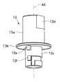
- FIG. The perspective view which shows the structure of the rotating shaft member in the said Embodiment 1.
- action of the 1st pulley and the 2nd pulley according to rotation of an angle operation knob and a rotating shaft member In the said Embodiment 1, the diagram which shows the rotation angle of the 1st pulley and the 2nd pulley according to the rotation angle of the rotating shaft member.
- the figure which shows the structure of the bending operation mechanism of the endoscope in Embodiment 2 of this invention Sectional drawing which shows the structure of the bending operation mechanism of an endoscope when it exists in the neutral position in the said Embodiment 2.
- FIG. Sectional drawing along the rotating shaft AX which shows the structure of the bending operation mechanism of the endoscope in the said Embodiment 2.
- FIG. 1 The chart which shows the effect
- FIG. 1 The chart which shows the effect
- the scale may be different for each component in order to make each component recognizable on the drawing. It is not limited only to the quantity of the described component, the shape of the component, the ratio of the size of the component, and the relative positional relationship of each component.
- FIG. 1 is a front view showing a configuration of an endoscope 1.
- the endoscope 1 can be introduced into a subject and is for optically observing the inside of the subject.
- the subject into which the endoscope 1 is introduced is an object to be observed, and may be a human body, a living body other than a human body, or an artificial object.
- some examples of artifacts are machines, buildings, and the like.
- the endoscope 1 is an electronic endoscope that captures an optical image of a subject
- the present invention is not limited to this, and an optical image is observed. It may be an optical endoscope for this purpose.
- the endoscope 1 includes an operation unit 2, an insertion unit 3, and a universal cord 4.
- the operation unit 2 is a part for the user to hold and operate.
- the operation unit 2 is provided with an angle operation knob 2a.
- the angle operation knob 2a is a rotation operation member for operating the bending of a bending portion 3b described later of the insertion portion 3.
- the angle operation knob 2a may be either a lever type or a dial type.
- the insertion part 3 is provided on the distal end side of the operation part 2 and is a part introduced into the subject.
- the insertion portion 3 includes a distal end portion 3a, a bending portion 3b, and a flexible tube portion 3c in order from the distal end side toward the proximal end side.
- the distal end portion 3a side (the insertion direction side to the subject and the distal end side when viewed from the user) of the insertion portion 3 is the distal end side, and the operation portion 2 side of the insertion portion 3 (in the insertion direction).
- the proximal end (proximal end side) viewed from the user side is referred to as the proximal end side.
- the distal end side is indicated by an arrow D
- the proximal end side is indicated by an arrow P.
- the distal end portion 3a is provided with an objective optical system and an illumination optical system.
- the distal end portion 3a includes an image pickup device for picking up an optical image formed by the objective optical system.
- An imaging unit is provided.
- the bending portion 3b is bent according to the operation of the angle operation knob 2a of the operation portion 2 described above.
- the bending portion 3b can be bent in the up-down direction (or in the left-right direction). Note that the vertical and horizontal directions of the curve are set to coincide with the vertical and horizontal directions of the subject image observed at the neutral position when the bending portion 3b is not curved.
- the bending direction is not limited to the above.
- Embodiment 2 described later an example in which the bending portion 3b can be bent in the vertical direction and the horizontal direction will be described.
- the configuration of the second embodiment which will be described later, it is possible to bend in an arbitrary direction around the insertion axis O by combining a vertical curve and a horizontal curve.
- the flexible tube portion 3c is a tubular portion having flexibility, and includes a light guide for transmitting illumination light to the objective optical system of the tip portion 3a, and a drive signal for driving the imaging unit of the tip portion 3a. And a signal line for transmitting the imaging signal obtained by the imaging unit are inserted.
- a rigid endoscope may be used.
- the universal cord 4 is extended from the side part of the operation part 2, for example.
- the above-described light guide and signal line are arranged.
- a connector 4 a for connecting to an external device is provided at the base end portion of the universal cord 4.
- the external device is a device that supplies the above-described illumination light and driving signal, receives the above-described imaging signal, and performs image processing and the like.
- FIG. 2 is a diagram showing the configuration of the bending operation mechanism of the endoscope 1
- FIG. 3 is a cross-sectional view showing the configuration of the bending operation mechanism of the endoscope 1 when in the neutral position
- FIG. 4 is an endoscope.
- FIG. 5 is a perspective view showing a configuration of the rotary shaft member 13
- FIG. 6 is a perspective view showing a configuration of the first pulley 15
- FIG. 7 is a first perspective view showing the configuration of the first pulley 15.
- 2 is a perspective view showing a configuration of a two pulley 16.
- the bending operation mechanism of the endoscope 1 includes a first wire 10a, a second wire 10b, an angle operation knob 2a attached to the operation unit frame 2b of the operation unit 2, a support shaft member 12, and a rotary shaft member 13.
- a flange portion 13b (to be described later) of the rotary shaft member 13, a first pulley 15, and a first torsion spring 17, A second pulley 16 and a second torsion spring 18 are disposed.
- the distal end portion of the first wire 10a is connected to the bending portion 3b.
- the bending portion 3b is bent in the first direction.
- the distal end portion of the second wire 10b is connected to the bending portion 3b.
- the bending portion 3b is bent in the second direction.
- the first direction is the up (U: up) direction and the second direction is the down (D: down) direction
- the first direction is left.
- the (L: left) direction and the second direction may be the right (R: right) direction.
- the support frame member 12 coaxial with the rotation axis AX of the angle operation knob 2a is provided on the operation section frame 2b.
- the support shaft member 12 is, for example, a hollow cylindrical member. Further, the rotation axis AX of the angle operation knob 2 a is disposed so as to be orthogonal to the insertion axis O of the insertion portion 3. In the configuration of the present embodiment, the support shaft member 12 may be omitted.
- the inner periphery of the rotating shaft member 13 having a cylindrical shape is fitted to the outer periphery of the support shaft member 12 so as to be rotatable.
- the rotating shaft member 13 includes a knob connecting portion 13 a, a flange portion 13 b, and a pulley driving portion 13 c.
- the angle operation knob 2a is fixed to the rotary shaft member 13 by fitting into the knob connecting portion 13a.
- the knob coupling portion 13a is provided with a knob fitting shape portion 13d. Accordingly, the angle operation knob 2a is rotated integrally with the rotary shaft member 13 by being fitted to the knob fitting shape portion 13d.
- the angle operation knob 2a is attached to the operation portion frame 2b using the rotary shaft member 13.
- the angle operation knob 2a and the rotation shaft member 13 are operation members that can rotate in the first rotation direction and the second rotation direction from the neutral position when the bending portion 3b is not bent.
- the flange portion 13b is disposed between the first pulley 15 and the knob side operation frame portion 2b1 of the operation portion frame 2b, and when the first pulley 15 rotates around the rotation axis AX, the knob side operation frame portion. 2b1 is prevented from sliding.
- the pulley drive part 13c has a first convex part 13e for rotating the first pulley 15 in the first rotational direction and a second convex part 13f for rotating the second pulley 16 in the second rotational direction. doing.
- the second rotation direction is opposite to the first rotation direction.
- the first pulley 15 is a first rotating member to which the proximal end portion of the first wire 10a is connected. By rotating the first pulley 15 in the first rotation direction, the first wire 10a is pulled.
- a wire groove 15b for winding up the first wire 10a is provided on the outer peripheral side of the first pulley 15. Further, the first pulley 15 is provided with a wire connecting portion 15c for connecting the proximal end portion of the first wire 10a.
- the wire connecting portion 15 c is closer to the proximal side than the rotational axis AX that is the rotational center of the first pulley 15 when the angle operation knob 2 a and the rotational shaft member 13 are positioned at the neutral position. It is arrange
- the first pulley 15 is formed with a first hole 15 a for receiving the rotating shaft member 13.
- the first hole 15a is formed with a first engagement portion 15f that engages with the first protrusion 13e when the rotary shaft member 13 rotates in the first rotation direction.
- a first inner diameter portion 15e is formed in the first hole 15a on the second rotation direction side of the first engagement portion 15f.
- the first inner diameter portion 15e has an inner radius larger than the rotation radius of the first convex portion 13e.
- the reason why the inner radius of the first inner diameter portion 15e is larger than the rotational radius of the first convex portion 13e is that when the rotary shaft member 13 rotates in the second rotational direction, the first convex portion 13e is the first engaging portion. This is to enable rotation away from 15f.
- a protrusion 15 d is provided on the outer periphery of the first pulley 15.
- a stopper portion 2d as shown in FIG. 3 and FIG.
- the second pulley 16 is a second rotating member to which the proximal end portion of the second wire 10b is connected. By rotating the second pulley 16 in the second rotation direction, the second wire 10b is pulled.
- the rotation center of the first pulley 15 and the rotation center of the second pulley 16 are both the rotation axis AX. Therefore, the first pulley 15 and the second pulley 16 are coaxial.
- a wire groove 16b for winding up the second wire 10b is provided on the outer peripheral side of the second pulley 16. Further, the second pulley 16 is provided with a wire connecting portion 16c for connecting the proximal end portion of the second wire 10b.
- the wire connection portion 16 c is closer to the proximal end than the rotation axis AX that is the rotation center of the second pulley 16 when the angle operation knob 2 a and the rotation shaft member 13 are positioned at the neutral position. It is arrange
- the second pulley 16 is formed with a second hole 16 a for receiving the rotating shaft member 13.
- the second hole 16a is formed with a second engagement portion 16f that engages with the second convex portion 13f when the rotary shaft member 13 rotates in the second rotation direction.
- a second inner diameter portion 16e is formed in the second hole 16a on the first rotation direction side of the second engagement portion 16f.
- the second inner diameter portion 16e has an inner radius larger than the rotation radius of the second convex portion 13f.
- the reason why the inner radius of the second inner diameter portion 16e is larger than the rotational radius of the second convex portion 13f is that when the rotary shaft member 13 rotates in the first rotational direction, the second convex portion 13f is the second engaging portion. This is to enable rotation away from 16f.
- a protrusion 16 d is provided on the outer periphery of the second pulley 16.
- the protrusion 16d abuts on the stopper portion 2d of the operation unit frame 2b described above, so that the rotation range of the second pulley 16 in the second rotation direction is increased. Be regulated.
- the rotation shaft member 13 and the angle operation knob 2a are restricted in the rotation range in the first rotation direction by the protrusion 15d of the first pulley 15 coming into contact with the stopper portion 2d, and the protrusion 16d of the second pulley 16 is The rotation range in the second rotation direction is regulated by coming into contact with the stopper portion 2d.
- the first torsion spring 17 is a first urging member that urges the first pulley 15 to return to the neutral position. Accordingly, the first convex portion 13e rotates away from the first engaging portion 15f and rotates in the second rotational direction when the angle operation knob 2a and the rotary shaft member 13 rotate in the second rotational direction from the neutral position. To do.
- the second torsion spring 18 is a second urging member that urges the second pulley 16 to return to the neutral position. Therefore, the second convex portion 13f rotates away from the second engaging portion 16f in the first rotational direction when the angle operation knob 2a and the rotary shaft member 13 rotate in the first rotational direction from the neutral position. To do.
- first torsion spring 17 and one end of the second torsion spring 18 are hung on a spring hook 2e provided on the operation portion frame 2b, for example, as shown in FIG. Further, since the first torsion spring 17 (or the second torsion spring 18) is provided, the thrust plate between the first pulley 15 and the second pulley 16 is not necessary.
- FIG. 8 is a chart showing the operation of the first pulley 15 and the second pulley 16 according to the rotation of the angle operation knob 2 a and the rotation shaft member 13, and FIG. 9 is a first view according to the rotation angle of the rotation shaft member 13. It is a diagram which shows the rotation angle of the pulley 15 and the 2nd pulley 16.
- FIG. 8 the left column of FIG. 8 related to the first pulley 15 shows the 8L-8L cross section of FIG. 4
- the right column of FIG. 8 related to the second pulley 16 shows the 8R-8R cross section of FIG.
- the rotation angles of the first pulley 15 and the second pulley 16 are shown with the neutral position as a reference (rotation angle 0 °). Further, the clockwise direction in FIGS. 3 and 8 is a positive direction RP of the rotation angle and a negative direction RM of the counterclockwise rotation angle.
- FIG 8 shows a state in which the first pulley 15 and the second pulley 16 are in the neutral position, that is, the rotation angle is 0 °.
- the first pulley 15 and the second pulley 16 automatically return to the neutral position by the tension of the first wire 10a and the second wire 10b when the angle operation knob 2a and the rotary shaft member 13 are returned to the neutral position. It has become.
- the first torsion spring 17 and the second torsion spring 18 are provided. Therefore, the first pulley 15 and the second pulley 16 are accurately returned to the neutral position by the urging force of the springs 17 and 18.
- the first convex portion 13e is engaged with the first engaging portion 15f, and the first pulley 15 is rotated by the rotating shaft member 13 (and the angle). It rotates together with the operation knob 2a).
- the second convex portion 13f freely rotates in the second inner diameter portion 16e and the second convex portion 13f and the second pulley 16 do not engage with each other, the second pulley 16 is caused by the action of the rotary shaft member 13. Does not rotate (see the -90 ° column in FIG. 8 and FIG. 9).
- the second wire 10b moves along with the bending of the bending portion 3b
- the second pulley 16 may rotate following the tension of the second wire 10b.
- the negative direction RM shown in FIGS. 8 and 9 is the first rotation direction described above.
- the positive direction RP shown in FIGS. 8 and 9 is the second rotational direction described above.
- the first convex portion 13e engages with the first engagement portion 15f and the first pulley 15 rotates.
- the second convex portion 13f freely rotates the second inner diameter portion 16e so that the second pulley 16 does not basically rotate.
- the second convex portion 13f engages with the second engaging portion 16f, the second pulley 16 rotates, and the first convex portion 13e
- the first pulley 15 was basically prevented from rotating by freely rotating the one inner diameter portion 15e.
- the bending operation mechanism of the endoscope 1 can be maintained and can maintain high bending operation accuracy even when repeated bending operations are performed.
- both the first wire 10a and the second wire 10b can be controlled by operating only one angle operation knob 2a. Therefore, the user interface of the bending operation mechanism of the present embodiment can be made equivalent to the conventional bending operation mechanism.
- the wire connecting portion between the wire and the pulley at the neutral position is on the tip side of the rotation axis AX, the wire is likely to be loosened.
- the wire connecting portions 15c and 16c are arranged so as to be located in the range PA on the proximal end side with respect to the rotation axis AX at the neutral position, the first and second wires 10a are disposed. , 10b can be prevented from occurring.
- first torsion spring 17 and the second torsion spring 18 are provided, the first pulley 15 and the second pulley 16 are accurately set to the neutral position when the angle operation knob 2a and the rotary shaft member 13 are in the neutral position. Can be returned to.
- the bending operation mechanism of the endoscope 1 that can perform the up-down (UD) operation with high accuracy and has few failures.
- the bending operation mechanism of the endoscope 1 that can perform the left-left (RL) operation with high accuracy and has few failures.
- FIG. 10 is a diagram showing a configuration of a bending operation mechanism of the endoscope 1.
- the bending direction of the bending portion 3b is two directions in the vertical direction (or the left-right direction). It is configured to be able to bend in an arbitrary direction around the insertion axis O by combining the bending in the vertical direction and the bending in the horizontal direction.
- the bending operation mechanism of the endoscope 1 includes a first bending operation mechanism unit related to bending in the vertical direction and a second bending operation mechanism unit related to bending in the left-right direction. ing.
- the first bending operation mechanism section includes a first group first wire 10Aa, a first group second wire 10Ab, a UD angle operation knob 2aA, a first rotating shaft member 13A, and a first rotating member.
- a first group first pulley 15A, a first group second pulley 16A as a second rotating member, a first group first torsion spring 17A, and a first group second torsion spring 18A are provided.
- the second bending operation mechanism section includes the second group first wire 10Ba, the second group second wire 10Bb, the RL angle operation knob 2aB, the second rotating shaft member 13B, and the first rotating member.
- a second group first pulley 15B, a second group second pulley 16B as a second rotating member, a second group first torsion spring 17B, and a second group second torsion spring 18B are provided.
- the angle operation knob 2a of the present embodiment includes a UD angle operation knob 2aA for operating up and down bending and an RL angle operation knob 2aB for operating left and right bending.
- FIG. 11 is a cross-sectional view showing the configuration of the bending operation mechanism of the endoscope 1 at the neutral position
- FIG. 12 is a cross-sectional view along the rotation axis AX showing the configuration of the bending operation mechanism of the endoscope 1.
- the UD angle operation knob 2aA is fixed integrally with the first rotating shaft member 13A at the knob connecting portion 13Aa
- the RL angle operating knob 2aB is fixed integrally with the second rotating shaft member 13B at the knob connecting portion 13Ba.
- the knob coupling portion 13Aa and the knob coupling portion 13Ba are provided with knob fitting shapes similar to the knob fitting shape portion 13d of the knob coupling portion 13a of the first embodiment described above. .
- the outer peripheral surface of the knob coupling portion 13Ba of the cylindrical second rotary shaft member 13B is slidably fitted to the inner peripheral surface of the cylindrical first rotary shaft member 13A.
- the first group first pulley 15A is disposed on the outer peripheral side of the pulley drive portion 13Ac of the first rotary shaft member 13A between the flange portion 13Ab of the first rotary shaft member 13A and the flange portion 13Bb of the second rotary shaft member 13B.
- the first group first torsion spring 17A, the first group second pulley 16A, and the first group second torsion spring 18A are sequentially arranged along the rotation axis AX.
- the second group first pulley 15B and the second group first pulley are sequentially arranged along the rotation axis AX.
- the first group first pulley 15A, the first group second pulley 16A, the second group first pulley 15B, and the second group first pulley The two pulleys 16B are arranged, and the number of pulleys is larger than the conventional configuration in which the up / down (UD) operation and the right left (RL) operation are performed with two pulleys. Therefore, the thickness T1 of the first group first pulley 15A, the thickness T2 of the first group second pulley 16A, the thickness T3 of the second group first pulley 15B, and the second group in the direction along the rotation axis AX.
- the thickness T4 of the second pulley 16B is set to be, for example, 7 mm or less, and the distance TA between the knob side operation frame portion 2b1 and the back side operation frame portion 2b2 is set to about 28 mm. Is preferred.
- the outer periphery of the pulley drive unit 13Ac and the outer periphery of the pulley drive unit 13Bc have the same diameter, and the first protrusion 13Ae provided on the outer periphery of the pulley drive unit 13Ac (in the following description, FIG. And the second convex portion 13Af, and the first convex portion 13Be and the second convex portion 13Bf provided on the outer periphery of the pulley driving portion 13Bc may be appropriately arranged.
- the first group first pulley 15A has a first hole 15Aa for receiving the first rotating shaft member 13A on the inner peripheral side.
- a second hole 16Aa for receiving the first rotating shaft member 13A is formed on the inner peripheral side.
- a wire groove 15Ab for winding the first group first wire 10Aa is formed on the outer peripheral side of the first group first pulley 15A, and a first group second wire 10Ab is wound on the outer peripheral side of the first group second pulley 16A. Wire grooves 16Ab are respectively provided.
- a first hole 15Ba for receiving the second rotating shaft member 13B is formed on the inner peripheral side.
- a second hole 16Ba for receiving the second rotary shaft member 13B is formed on the inner peripheral side.
- a wire groove 15Bb for winding up the second group first wire 10Ba is formed on the outer peripheral side of the second group first pulley 15B, and a second group second wire 10Bb is wound up on the outer peripheral side of the second group second pulley 16B.
- the wire grooves 16Bb are respectively provided.
- the base end portion of the first group first wire 10Aa is connected to the wire connection portion 15Ac of the first group first pulley 15A, and the first group second wire is connected to the wire connection portion 16Ac of the first group second pulley 16A.
- the proximal end portion of the wire 10Ab is connected.
- the proximal end portion of the second group first wire 10Ba is connected to the wire connection portion 15Bc of the second group first pulley 15B, and the second group second wire is connected to the wire connection portion 16Bc of the second group second pulley 16B.
- the proximal end portion of the wire 10Bb is connected.
- the wire connection portion 15Ac, the wire connection portion 16Ac, the wire connection portion 15Bc, and the wire connection portion 16Bc are more basic than the rotary shaft AX.
- the arrangement in the end range PA is the same as in the first embodiment.
- first pulley 15A similarly to the first pulley 15 of the first embodiment described above, a protrusion 15Ad for contacting the stopper portion 2d and an inner radius larger than the rotation radius of the first convex portion 13Ae are provided.
- a first inner diameter portion 15Ae having a radius and a first engagement portion 15Af for engaging the first convex portion 13Ae are provided.
- the first group second pulley 16A has a protrusion 16Ad for contacting the stopper portion 2d and an inner radius larger than the rotation radius of the second convex portion 13Af.
- a second inner diameter portion 16Ae having a second engaging portion 16Af for engaging with the second convex portion 13Af is provided.
- the second group first pulley 15B has a protrusion 15Bd for contacting the stopper portion 2d and an inner radius larger than the rotation radius of the first convex portion 13Be.
- a first inner diameter portion 15Be having a first engagement portion 15Bf for engaging the first convex portion 13Be is provided.
- the second group second pulley 16B has a protrusion 16Bd for contacting the stopper portion 2d and an inner radius larger than the rotation radius of the second convex portion 13Bf.
- a second inner diameter portion 16Be having a second engaging portion 16Bf for engaging with the second convex portion 13Bf is provided.
- FIG. 13 is a chart showing the action of the first group first pulley 15A and the first group second pulley 16A according to the rotation of the UD angle operation knob 2aA and the first rotating shaft member 13A.
- the left column of FIG. 13 related to the first group first pulley 15A shows a 13L-13L cross section of FIG. 12
- the right column of FIG. 13 related to the first group second pulley 16A shows a 13R-13R cross section of FIG. Is shown.
- the first group first torsion spring 17A and the first group second torsion spring 18A are provided, the first group first pulley 15A and the first group second pulley 16A accurately return to the neutral position. This is the same as in the first embodiment described above. Further, since the first group first torsion spring 17A (or further, the first group second torsion spring 18A) is provided, the thrust plate between the first group first pulley 15A and the first group second pulley 16A is provided. Is no longer needed.
- the first group second pulley 16A may rotate following the tension of the first group second wire 10Ab.
- the negative direction RM shown in FIG. 13 is the first rotation direction.
- the UD angle operation knob 2aA and the first rotating shaft member 13A are rotated in the forward direction RP from the neutral position, the second convex portion 13Af is engaged with the second engaging portion 16Af, and the first group second pulley 16A is engaged. Rotates together with the first rotating shaft member 13A (and the UD angle operation knob 2aA). At this time, the first convex portion 13Ae freely rotates in the first inner diameter portion 15Ae, and the first convex portion 13Ae and the first group first pulley 15A do not engage with each other. It does not rotate due to the action of the single rotation shaft member 13A (see the + 90 ° column in FIG. 13).
- the first group first pulley 15A may rotate by following the tension of the first group first wire 10Aa.
- the positive direction RP shown in FIG. 13 is the second rotation direction.
- FIG. 14 is a chart showing the operation of the second group first pulley 15B and the second group second pulley 16B according to the rotation of the RL angle operation knob 2aB and the second rotation shaft member 13B.
- the left column of FIG. 14 relating to the second group first pulley 15B shows the 14L-14L cross section of FIG. 12
- the right column of FIG. 14 relating to the second group second pulley 16B is the 14R-14R cross section of FIG. Is shown.
- the second group first torsion spring 17B and the second group second torsion spring 18B are provided, the second group first pulley 15B and the second group second pulley 16B are accurately returned to the neutral position. This is the same as in the first embodiment described above. Further, since the second group first torsion spring 17B (or the second group second torsion spring 18B) is provided, the thrust plate between the second group first pulley 15B and the second group second pulley 16B is provided. Is no longer needed.
- the negative direction RM shown in FIG. 14 is the first rotation direction.
- the second group first pulley 15B may rotate following the tension of the second group first wire 10Ba.
- the positive direction RP shown in FIG. 14 is the second rotation direction.
- the effects similar to those of the first embodiment described above can be obtained, and the up / down (UD) operation and the right left (RL) operation can be combined and performed with high accuracy. It becomes a bending operation mechanism of the endoscope 1 with few failures.
- the pulleys 15A, 16A, 15B, and 16B are each configured to have a thickness of 7 mm or less so that the distance TA between the knob-side operation frame portion 2b1 and the back-side operation frame portion 2b2 is about 28 mm.
- the size of the operation unit 2 in the direction of the rotation axis AX can be maintained equivalent to that of the conventional operation unit, and practical operability equivalent to the conventional one can be ensured.
- the wire connecting portions are arranged so as to be in the range PA on the base end side with respect to the rotation axis AX at the neutral position, but this is a preferable arrangement example. Therefore, it is not prohibited to arrange the wire connecting portions at the neutral position outside the range PA, and they may be arranged by design or for other reasons.
- the bending operation mechanism of the endoscope 1 has been described.
- the field of application of the bending operation mechanism is not limited to the endoscope 1, and for example, high accuracy and reliability such as an electric manipulator and a robot arm.
- the present invention can also be applied to the field of wire pulling operation mechanisms that require high performance.
- the first convex portion and the second convex portion are provided on the rotary shaft member that is the operation member, and the first engaging portion and the first convex portion are engaged with the first pulley that is the first rotary member.
- the first convex portion is provided on the inner diameter side of the first pulley that is the first rotating member
- the second convex portion is provided on the inner diameter side of the second pulley that is the second rotating member.
- a first engaging portion that engages with the first convex portion, a first outer diameter portion that has an outer radius smaller than the rotation radius of the first convex portion, a second engaging portion that engages with the second convex portion, and a first A second outer diameter portion having an outer radius smaller than the rotation radius of the two convex portions may be formed so as to function in the same manner as described above.
- when the operation member rotates in the first rotation direction only the first rotation member is engaged
- only the second rotation member is engaged. May be engaged.
- the present invention is not limited to the above-described embodiment as it is, and can be embodied by modifying the constituent elements without departing from the scope of the invention in the implementation stage. Further, various aspects of the invention can be formed by appropriately combining a plurality of constituent elements disclosed in the embodiment. For example, some components may be deleted from all the components shown in the embodiment. Furthermore, constituent elements over different embodiments may be appropriately combined. Thus, it goes without saying that various modifications and applications are possible without departing from the spirit of the invention.
Landscapes
- Health & Medical Sciences (AREA)
- Life Sciences & Earth Sciences (AREA)
- Surgery (AREA)
- Physics & Mathematics (AREA)
- Optics & Photonics (AREA)
- Biomedical Technology (AREA)
- Animal Behavior & Ethology (AREA)
- Radiology & Medical Imaging (AREA)
- Nuclear Medicine, Radiotherapy & Molecular Imaging (AREA)
- Engineering & Computer Science (AREA)
- Biophysics (AREA)
- Heart & Thoracic Surgery (AREA)
- Medical Informatics (AREA)
- Molecular Biology (AREA)
- Pathology (AREA)
- General Health & Medical Sciences (AREA)
- Public Health (AREA)
- Veterinary Medicine (AREA)
- Astronomy & Astrophysics (AREA)
- General Physics & Mathematics (AREA)
- Endoscopes (AREA)
- Instruments For Viewing The Inside Of Hollow Bodies (AREA)
Abstract
第1の回転方向に回転させることにより第1ワイヤ(10a)を牽引する第1プーリ(15)と、第1の回転方向と逆方向の第2の回転方向に回転させることにより第2ワイヤ(10b)を牽引する、回転中心が第1プーリ(15)と同軸の第2プーリ(16)と、湾曲部が湾曲していないときのニュートラル位置から、第1の回転方向に回転するときに第1プーリ(15)のみと係合し、第2の回転方向に回転するときに第2プーリ(16)のみと係合する回転軸部材(13)と、を備える内視鏡の湾曲操作機構。
Description
本発明は、ワイヤを牽引することにより湾曲部を湾曲させる内視鏡の湾曲操作機構に関する。
内視鏡におけるワイヤを用いた湾曲操作機構は、ワイヤの先端部を内視鏡の湾曲部に接続すると共に、操作部に設けられたプーリにワイヤの基端部を接続する構成となっている。そして、プーリを回転させるためのアングル操作ノブを操作してワイヤを牽引することにより、ワイヤにテンションがかかり、このテンションによって湾曲部を湾曲させるようになっている。
このような湾曲操作機構において、プーリに接続されているワイヤは、一端側を牽引すると、他端側が緩むことがある。そこで、こうしたワイヤの緩みを吸収する技術が、従来より提案されている。
例えば、日本国特開2005-218569号公報に記載の内視鏡装置は、内視鏡挿入部の湾曲部からそれぞれ延出し、湾曲部を少なくとも2つの方向に湾曲操作する一対の操作ワイヤと、一対の操作ワイヤが巻き付けられたプーリを有するプーリユニットと、一対の操作ワイヤの基端部にそれぞれ設けられた口金部と、プーリユニットに、各口金部をそれぞれ係脱自在に保持することにより、一対の操作ワイヤをそれぞれ牽引弛緩して湾曲部を湾曲操作する、プーリユニットに回動自在に保持された係止部と、が設けられている。
上述したように、回転部材であるプーリを回転して湾曲部を湾曲させる構成の湾曲操作機構においては、湾曲操作を行うときに、プーリにかけられたワイヤの一方に引張力がかかり、ワイヤの他方に圧縮力がかかることがある。そして、圧縮力がかかったワイヤは、プーリとマニホールドとの間でたわみが生じて意図しない方向に移動し、プーリから脱輪することがある。
上記日本国特開2005-218569号公報に記載の技術では、係止部に挿通された操作ワイヤが、係止部内で摺動するために圧縮力がかかるのを緩和することができる。しかし、操作ワイヤが摺動するときに係止部との間で摩擦力が生じるために、ワイヤの摺動部分が磨耗して、ワイヤの強度が劣化する要因となる。さらに、摩擦力によってワイヤの挿通が制止され、たわみが生じてワイヤがプーリから脱輪する可能性がある。
こうしてワイヤがプーリから脱輪すると、湾曲角度の低下、ワイヤ切れなどの動作不良につながってしまう。
本発明は上記事情に鑑みてなされたものであり、ワイヤに圧縮力がかかるのを防止してプーリからのワイヤの脱輪を防ぐことができ、かつ繰り返し湾曲操作を行っても高い湾曲操作精度を維持することができる内視鏡の湾曲操作機構を提供することを目的としている。
本発明の一態様による内視鏡の湾曲操作機構は、第1のワイヤの先端部が内視鏡の挿入部に設けられた湾曲部に接続され、前記第1のワイヤを牽引することにより前記湾曲部が第1の方向に湾曲する、前記第1のワイヤと、第2のワイヤの先端部が前記湾曲部に接続され、前記第2のワイヤを牽引することにより前記湾曲部が第2の方向に湾曲する、前記第2のワイヤと、前記第1のワイヤの基端部が第1の回転部材に接続され、前記第1の回転部材を第1の回転方向に回転させることにより前記第1のワイヤが牽引される、前記第1の回転部材と、前記第2のワイヤの基端部が第2の回転部材に接続され、前記第2の回転部材を前記第1の回転方向と逆方向の第2の回転方向に回転させることにより前記第2のワイヤが牽引される、前記第2の回転部材の回転中心が前記第1の回転部材の回転中心と同軸である、前記第2の回転部材と、前記湾曲部が湾曲していないときのニュートラル位置から前記第1の回転方向および前記第2の回転方向に回転可能であって、前記第1の回転方向に回転するときに前記第1の回転部材および前記第2の回転部材の内の前記第1の回転部材のみと係合し、前記第2の回転方向に回転するときに前記第1の回転部材および前記第2の回転部材の内の前記第2の回転部材のみと係合する操作部材と、を具備する。
以下、図面を参照して本発明の実施の形態を説明する。
なお、以下の説明に用いる各図においては、各構成要素を図面上で認識可能な程度の大きさとするために、構成要素毎に縮尺を異ならせることがあり、本発明は、これらの図に記載された構成要素の数量、構成要素の形状、構成要素の大きさの比率、および各構成要素の相対的な位置関係のみに限定されるものではない。
[実施形態1]
図1から図9は本発明の実施形態1を示したものであり、図1は内視鏡1の構成を示す正面図である。
図1から図9は本発明の実施形態1を示したものであり、図1は内視鏡1の構成を示す正面図である。
内視鏡1は、被検体内に導入可能であって、被検体内を光学的に観察するためのものである。ここに、内視鏡1が導入される被検体は、観察の対象となる物体であって、人体、人体以外の生体、人工物の何れでも構わない。ここに、人工物の幾つかの例は、機械、建造物等である。
また、本実施形態においては、内視鏡1が被検体の光学像を撮像する電子内視鏡である場合を例に挙げて説明するが、これに限定されるものではなく、光学像を観察するための光学内視鏡であっても構わない。
内視鏡1は、操作部2と、挿入部3と、ユニバーサルコード4と、を備えている。
操作部2は、ユーザが把持して操作を行うための部位である。操作部2には、アングル操作ノブ2aが設けられている。アングル操作ノブ2aは、挿入部3の後述する湾曲部3bの湾曲を操作するための回動操作部材である。このアングル操作ノブ2aは、レバータイプ、ダイヤルタイプ等の何れでも構わない。
挿入部3は、操作部2の先端側に設けられており、被検体の内部に導入される部位である。挿入部3は、先端側から基端側へ向かって順に、先端部3aと、湾曲部3bと、可撓管部3cと、を備えている。なお、挿入部3の先端部3a側(被検体への挿入方向側であり、ユーザから見て遠位端(distal end)側)を先端側、挿入部3の操作部2側(挿入方向の反対方向側であり、ユーザから見て近位端(proximal end)側)を基端側と呼ぶことにする。また、図面において、先端側を矢印Dにより示し、基端側を矢印Pにより示している。
先端部3aには、対物光学系および照明光学系が設けられ、内視鏡1が電子内視鏡である場合には、対物光学系により結像された光学像を撮像する撮像素子等を含む撮像ユニットが設けられている。
湾曲部3bは、上述した操作部2のアングル操作ノブ2aの操作に応じて湾曲される。湾曲部3bは、本実施形態においては、例えば上下方向(あるいは左右方向でも構わない)に湾曲可能であるものとする。なお、湾曲の上下方向および左右方向は、湾曲部3bが湾曲していないときのニュートラル位置において観察される被写体像の上下方向および左右方向に一致するように設定されている。
ただし、湾曲方向は上述に限定されるものではなく、例えば後述する実施形態2においては、湾曲部3bが上下方向および左右方向に湾曲可能である例を説明する。後述する実施形態2の構成では、上下方向の湾曲と左右方向の湾曲とを組み合わせることで、挿入軸O周りの任意方向に湾曲することが可能となっている。
可撓管部3cは、可撓性を有する管状部であり、内部には、照明光を先端部3aの対物光学系へ伝送するためのライトガイド、先端部3aの撮像ユニットを駆動する駆動信号を伝送する信号線、および撮像ユニットにより得られた撮像信号を伝送する信号線などが挿通されている。なお、ここでは内視鏡1が、可撓管部3cを備える軟性鏡である場合を例に挙げたが、硬性鏡であっても構わない。
ユニバーサルコード4は、例えば、操作部2の側部から延出されている。ユニバーサルコード4内には、上述したライトガイドおよび信号線が配置されている。ユニバーサルコード4の基端部には、外部装置に接続するためのコネクタ4aが設けられている。外部装置は、上述した照明光および駆動信号を供給し、上述した撮像信号を受信して画像処理等を行う装置である。
次に、図2は内視鏡1の湾曲操作機構の構成を示す図、図3はニュートラル位置にあるときの内視鏡1の湾曲操作機構の構成を示す断面図、図4は内視鏡1の湾曲操作機構の構成を示す回転軸AXに沿った断面図、図5は回転軸部材13の構成を示す斜視図、図6は第1プーリ15の構成を示す斜視図、図7は第2プーリ16の構成を示す斜視図である。
内視鏡1の湾曲操作機構は、第1ワイヤ10aと、第2ワイヤ10bと、操作部2の操作部枠2bに取り付けられたアングル操作ノブ2aと、支持軸部材12と、回転軸部材13と、第1の回転部材である第1プーリ15と、第2の回転部材である第2プーリ16と、第1ねじりバネ17と、第2ねじりバネ18と、を備えている。
ここに、操作部枠2bのノブ側操作枠部2b1から裏側操作枠部2b2へ向かって順に、回転軸部材13の後述するフランジ部13bと、第1プーリ15と、第1ねじりバネ17と、第2プーリ16と、第2ねじりバネ18と、が配設されている。
第1ワイヤ10aは、内視鏡1の挿入部3に設けられたマニホールド3c1を経由した後に、第1ワイヤ10aの先端部が湾曲部3bに接続されている。第1ワイヤ10aを牽引することにより、湾曲部3bが第1の方向に湾曲するようになっている。
第2ワイヤ10bは、内視鏡1の挿入部3に設けられたマニホールド3c1を経由した後に、第2ワイヤ10bの先端部が湾曲部3bに接続されている。第2ワイヤ10bを牽引することにより、湾曲部3bが第2の方向に湾曲するようになっている。
本実施形態においては、第1の方向を上(U:アップ)方向、第2の方向を下(D:ダウン)方向とする例を説明するが、上述したように、第1の方向を左(L:レフト)方向、第2の方向を右(R:ライト)方向としても構わない。
操作部枠2bには、アングル操作ノブ2aの回転軸AXと同軸の支持軸部材12が設けられている。支持軸部材12は、例えば、中空の円筒状部材である。また、アングル操作ノブ2aの回転軸AXは、挿入部3の挿入軸Oと直交するように配置されている。なお、本実施形態の構成においては、支持軸部材12を省略しても構わない。
支持軸部材12の外周に、円筒状をなす回転軸部材13の内周が、回動可能に嵌め合わされている。回転軸部材13は、図5に示すように、ノブ連結部13aと、フランジ部13bと、プーリ駆動部13cと、を有している。
アングル操作ノブ2aは、ノブ連結部13aに嵌合することで、回転軸部材13に固定されている。ここで、ノブ連結部13aには、ノブ嵌合形状部13dが設けられている。従って、ノブ嵌合形状部13dと嵌合することにより、アングル操作ノブ2aは、回転軸部材13と一体に回動するようになっている。こうして、アングル操作ノブ2aは、回転軸部材13を用いて、操作部枠2bに取り付けられている。
アングル操作ノブ2aおよび回転軸部材13は、湾曲部3bが湾曲していないときのニュートラル位置から第1の回転方向および第2の回転方向に回転可能な操作部材である。
フランジ部13bは、第1プーリ15と、操作部枠2bのノブ側操作枠部2b1と、の間に配置され、第1プーリ15が回転軸AX周りに回転する際に、ノブ側操作枠部2b1と摺動するのを防止している。
プーリ駆動部13cは、第1プーリ15を第1の回転方向に回転させるための第1凸部13eと、第2プーリ16を第2の回転方向に回転させる第2凸部13fと、を有している。ここに、第2の回転方向は、第1の回転方向と逆方向である。
第1プーリ15は、第1ワイヤ10aの基端部が接続される第1の回転部材である。第1プーリ15を第1の回転方向に回転させることにより、第1ワイヤ10aが牽引される。
第1プーリ15の外周側には、第1ワイヤ10aを巻き上げるためのワイヤ溝15bが設けられている。さらに、第1プーリ15には、第1ワイヤ10aの基端部を接続するためのワイヤ接続部15cが設けられている。
図3に示すように、ワイヤ接続部15cは、アングル操作ノブ2aおよび回転軸部材13がニュートラル位置に位置決めされているときに、第1プーリ15の回転中心である回転軸AXよりも基端側の範囲PAにあるように配置されている。従って、第1ワイヤ10aの基端部は、ニュートラル位置のときに、第1プーリ15の回転中心よりも基端側の範囲PAにおいて第1プーリ15に接続されている。
また、第1プーリ15には、図6に示すように、回転軸部材13を受け入れる第1の孔15aが形成されている。
第1の孔15aには、回転軸部材13が第1の回転方向に回転するときに第1凸部13eが係合する第1係合部15fが形成されている。
さらに、第1の孔15aには、第1係合部15fの第2の回転方向側に、第1内径部15eが形成されている。第1内径部15eは、第1凸部13eの回転半径よりも大きい内半径を有している。第1内径部15eの内半径が第1凸部13eの回転半径よりも大きい理由は、回転軸部材13が第2の回転方向に回転するときに、第1凸部13eが第1係合部15fから離れて回転できるようにするためである。
そして、第1プーリ15の外周には、突起15dが設けられている。一方、操作部枠2bの、突起15dの回転経路上には、図3および後述する図8等に示すようなストッパ部2dが設けられている。そして、第1プーリ15が第1の回転方向へ回転したときに、突起15dがストッパ部2dに当接することで、第1プーリ15の第1の回転方向への回転範囲が規制される。
第2プーリ16は、第2ワイヤ10bの基端部が接続される第2の回転部材である。第2プーリ16を第2の回転方向に回転させることにより、第2ワイヤ10bが牽引される。
ここに、第1プーリ15の回転中心と第2プーリ16の回転中心とは、何れも回転軸AXである。従って、第1プーリ15と第2プーリ16とは同軸となっている。
第2プーリ16の外周側には、第2ワイヤ10bを巻き上げるためのワイヤ溝16bが設けられている。さらに、第2プーリ16には、第2ワイヤ10bの基端部を接続するためのワイヤ接続部16cが設けられている。
図3に示すように、ワイヤ接続部16cは、アングル操作ノブ2aおよび回転軸部材13がニュートラル位置に位置決めされているときに、第2プーリ16の回転中心である回転軸AXよりも基端側の範囲PAにあるように配置されている。従って、第2ワイヤ10bの基端部は、ニュートラル位置のときに、第2プーリ16の回転中心よりも基端側の範囲PAにおいて第2プーリ16に接続されている。
また、第2プーリ16には、図7に示すように、回転軸部材13を受け入れる第2の孔16aが形成されている。
第2の孔16aには、回転軸部材13が第2の回転方向に回転するときに第2凸部13fが係合する第2係合部16fが形成されている。
さらに、第2の孔16aには、第2係合部16fの第1の回転方向側に、第2内径部16eが形成されている。第2内径部16eは、第2凸部13fの回転半径よりも大きい内半径を有している。第2内径部16eの内半径が第2凸部13fの回転半径よりも大きい理由は、回転軸部材13が第1の回転方向に回転するときに、第2凸部13fが第2係合部16fから離れて回転できるようにするためである。
そして、第2プーリ16の外周には、突起16dが設けられている。第2プーリ16が第2の回転方向へ回転したときに、突起16dが上述した操作部枠2bのストッパ部2dに当接することで、第2プーリ16の第2の回転方向への回転範囲が規制される。
こうして、回転軸部材13およびアングル操作ノブ2aは、第1プーリ15の突起15dがストッパ部2dに当接することで第1の回転方向への回転範囲が規制され、第2プーリ16の突起16dがストッパ部2dに当接することで第2の回転方向への回転範囲が規制されるようになっている。
第1ねじりバネ17は、第1プーリ15を、ニュートラル位置に復帰させるように付勢する第1の付勢部材である。従って、第1凸部13eは、アングル操作ノブ2aおよび回転軸部材13がニュートラル位置よりも第2の回転方向に回転するときに、第1係合部15fから離れて第2の回転方向に回転する。
第2ねじりバネ18は、第2プーリ16を、ニュートラル位置に復帰させるように付勢する第2の付勢部材である。従って、第2凸部13fは、アングル操作ノブ2aおよび回転軸部材13がニュートラル位置よりも第1の回転方向に回転するときに、第2係合部16fから離れて第1の回転方向に回転する。
なお、第1ねじりバネ17の一端、および第2ねじりバネ18の一端は、例えば図3に示すように、操作部枠2bに設けられたバネ掛け2eに掛けられている。また、第1ねじりバネ17(あるいはさらに第2ねじりバネ18)を設けているために、第1プーリ15と第2プーリ16との間のスラストプレートは不要となっている。
次に、図8はアングル操作ノブ2aおよび回転軸部材13の回転に応じた第1プーリ15および第2プーリ16の作用を示す図表、図9は回転軸部材13の回転角度に応じた第1プーリ15および第2プーリ16の回転角度を示す線図である。ここに、第1プーリ15に係る図8の左欄は図4の8L-8L断面を示し、第2プーリ16に係る図8の右欄は図4の8R-8R断面を示している。
なお、図8および図9において、ニュートラル位置を基準(回転角度0°)として、第1プーリ15および第2プーリ16の回転角度を示している。また、図3および図8における時計回りを回転角度の正方向RP、反時計回りの回転角度の負方向RMとしている。
図8のニュートラル欄は、第1プーリ15および第2プーリ16がニュートラル位置、つまり回転角度0°にあるときの様子を示している。なお、第1プーリ15および第2プーリ16は、アングル操作ノブ2aおよび回転軸部材13をニュートラル位置に戻すと、第1ワイヤ10aおよび第2ワイヤ10bの張力により自動的にニュートラル位置に戻るようになっている。
ただし、もし張力の作用のみでは第1プーリ15および第2プーリ16にニュートラル位置からのずれが生じることがある場合でも、上述したように、第1ねじりバネ17および第2ねじりバネ18を設けているために、各バネ17,18の付勢力により、第1プーリ15および第2プーリ16が正確にニュートラル位置に戻るようになっている。
ニュートラル位置からアングル操作ノブ2aおよび回転軸部材13を負方向RMに回転すると、第1凸部13eが第1係合部15fに係合して、第1プーリ15が回転軸部材13(およびアングル操作ノブ2a)と一体に回動する。このときには、第2凸部13fは第2内径部16e内を自由回転し、第2凸部13fと第2プーリ16とは係合しないために、第2プーリ16は回転軸部材13の作用によっては回転しない(図8の-90°欄、および図9参照)。ただし、湾曲部3bの湾曲に伴って第2ワイヤ10bが移動した場合に、第2ワイヤ10bの張力に従動して第2プーリ16が回転しても構わない。こうして、図8および図9に示す負方向RMは、上述した第1の回転方向となっている。
一方、ニュートラル位置からアングル操作ノブ2aおよび回転軸部材13を正方向RPに回転すると、第2凸部13fが第2係合部16fに係合して、第2プーリ16が回転軸部材13(およびアングル操作ノブ2a)と一体に回動する。このときには、第1凸部13eは第1内径部15e内を自由回転し、第1凸部13eと第1プーリ15とは係合しないために、第1プーリ15は回転軸部材13の作用によっては回転しない(図8の+90°欄、および図9参照)。ただし、湾曲部3bの湾曲に伴って第1ワイヤ10aが移動した場合に、第1ワイヤ10aの張力に従動して第1プーリ15が回転しても構わない。こうして、図8および図9に示す正方向RPは、上述した第2の回転方向となっている。
このような実施形態1によれば、回転軸部材13が第1の回転方向に回転するときには、第1凸部13eが第1係合部15fと係合して第1プーリ15が回転すると共に、第2凸部13fが第2内径部16eを自由回転して第2プーリ16は基本的に回転しないようにした。さらに、回転軸部材13が第2の回転方向に回転するときには、第2凸部13fが第2係合部16fと係合して第2プーリ16が回転すると共に、第1凸部13eが第1内径部15eを自由回転して第1プーリ15は基本的に回転しないようにした。このために、第1,第2ワイヤ10a,10bに圧縮力がかかるのを防止して第1,第2プーリ15,16からの第1,第2ワイヤ10a,10bの脱輪を防ぐことができ、かつ繰り返し湾曲操作を行っても高い湾曲操作精度を維持することができる内視鏡1の湾曲操作機構となる。
また、第1プーリ15を第1の回転方向に回転させる第1凸部13eと、第2プーリ16を第2の回転方向に回転させる第2凸部13fと、を回転軸部材13に設けたために、1つのアングル操作ノブ2aを操作するだけで第1ワイヤ10aおよび第2ワイヤ10bの両方を制御することができる。従って、本実施形態の湾曲操作機構のユーザーインタフェースを、従来の湾曲操作機構と同等にすることができる。
そして、回転軸部材13がニュートラル位置よりも第2の回転方向に回転するときには、第1凸部13eが第1係合部15fから離れて第2の回転方向に回転し、回転軸部材13がニュートラル位置よりも第1の回転方向に回転するときには、第2凸部13fが第2係合部16fから離れて第1の回転方向に回転するようにしたために、ニュートラル位置を区分として、第1,第2ワイヤ10a,10bに圧縮力がかかるのを正確に防止することができる。
ところで、ニュートラル位置におけるワイヤとプーリとの接続部が回転軸AXよりも先端側にあると、ワイヤに緩みが発生し易い。これに対して本実施形態によれば、ニュートラル位置のときに回転軸AXよりも基端側の範囲PAに位置するようにワイヤ接続部15c,16cを配置したために、第1,第2ワイヤ10a,10bに弛みが発生するのを防止することができる。
さらに、第1ねじりバネ17および第2ねじりバネ18を設けたために、アングル操作ノブ2aおよび回転軸部材13がニュートラル位置になったときに、第1プーリ15および第2プーリ16をニュートラル位置に正確に戻すことができる。
また、第1の方向を上方向、第2の方向を下方向としたときには、アップダウン(UD)操作を高い精度で行うことができる、故障の少ない内視鏡1の湾曲操作機構となる。
一方、第1の方向を左方向、第2の方向を右方向としたときには、ライトレフト(RL)操作を高い精度で行うことができる、故障の少ない内視鏡1の湾曲操作機構となる。
[実施形態2]
図10から図14は本発明の実施形態2を示したものであり、図10は内視鏡1の湾曲操作機構の構成を示す図である。
図10から図14は本発明の実施形態2を示したものであり、図10は内視鏡1の湾曲操作機構の構成を示す図である。
この実施形態2において、上述の実施形態1と同様である部分については同一の符号を付すなどして説明を適宜省略し、主として異なる点についてのみ説明する。
上述した実施形態1は、湾曲部3bの湾曲方向が上下方向(または、左右方向)の2方向となっていたが、本実施形態は、湾曲部3bの湾曲方向を上下方向および左右方向の4方向とし、ひいては、上下方向の湾曲と左右方向の湾曲とを組み合わせることで、挿入軸O周りの任意方向に湾曲することができるように構成したものとなっている。
このために、本実施形態の内視鏡1の湾曲操作機構は、上下方向の湾曲に係る第1の湾曲操作機構部と、左右方向の湾曲に係る第2の湾曲操作機構部と、を備えている。
第1の湾曲操作機構部は、第1群第1ワイヤ10Aaと、第1群第2ワイヤ10Abと、UDアングル操作ノブ2aAと、第1回転軸部材13Aと、第1の回転部材である第1群第1プーリ15Aと、第2の回転部材である第1群第2プーリ16Aと、第1群第1ねじりバネ17Aと、第1群第2ねじりバネ18Aと、を備えている。
第2の湾曲操作機構部は、第2群第1ワイヤ10Baと、第2群第2ワイヤ10Bbと、RLアングル操作ノブ2aBと、第2回転軸部材13Bと、第1の回転部材である第2群第1プーリ15Bと、第2の回転部材である第2群第2プーリ16Bと、第2群第1ねじりバネ17Bと、第2群第2ねじりバネ18Bと、を備えている。
本実施形態のアングル操作ノブ2aは、上下方向の湾曲を操作するためのUDアングル操作ノブ2aAと、左右方向の湾曲を操作するためのRLアングル操作ノブ2aBと、を備えている。
図11はニュートラル位置にあるときの内視鏡1の湾曲操作機構の構成を示す断面図、図12は内視鏡1の湾曲操作機構の構成を示す回転軸AXに沿った断面図である。
UDアングル操作ノブ2aAはノブ連結部13Aaにおいて第1回転軸部材13Aと回動一体に固定され、RLアングル操作ノブ2aBはノブ連結部13Baにおいて第2回転軸部材13Bと回動一体に固定されている。なお、図示はしないが、ノブ連結部13Aaおよびノブ連結部13Baには、上述した実施形態1のノブ連結部13aのノブ嵌合形状部13dと同様のノブ嵌合形状部がそれぞれ設けられている。
円筒状をなす第1回転軸部材13Aの内周面に、円筒状をなす第2回転軸部材13Bのノブ連結部13Baの外周面が摺動可能に嵌め合わされている。
第1回転軸部材13Aのフランジ部13Abと、第2回転軸部材13Bのフランジ部13Bbとの間における、第1回転軸部材13Aのプーリ駆動部13Acの外周側に、第1群第1プーリ15Aと、第1群第1ねじりバネ17Aと、第1群第2プーリ16Aと、第1群第2ねじりバネ18Aと、が回転軸AXに沿って順に配置されている。
第2回転軸部材13Bのフランジ部13Bbと裏側操作枠部2b2との間における、第2回転軸部材13Bのプーリ駆動部13Bcの外周側に、第2群第1プーリ15Bと、第2群第1ねじりバネ17Bと、第2群第2プーリ16Bと、第2群第2ねじりバネ18Bと、が回転軸AXに沿って順に配置されている。
なお、本実施形態では、回転軸AXに沿って4つのプーリ、すなわち、第1群第1プーリ15Aと、第1群第2プーリ16Aと、第2群第1プーリ15Bと、第2群第2プーリ16Bと、が配置された構成となっており、2つのプーリでアップダウン(UD)操作およびライトレフト(RL)操作を行う従来の構成よりもプーリの数が多い。そこで、回転軸AXに沿った方向の、第1群第1プーリ15Aの厚みT1と、第1群第2プーリ16Aの厚みT2と、第2群第1プーリ15Bの厚みT3と、第2群第2プーリ16Bの厚みT4とを、それぞれ例えば7mm以下になるように設定すると共に、ノブ側操作枠部2b1と裏側操作枠部2b2との間の距離TAが約28mmとなるように構成することが好ましい。このような構成を採用することにより、操作部2の回転軸AX方向の大きさを従来の操作部と同等に維持して、従来と同等の実用的な操作性を確保することができる。
また、第1群第1プーリ15Aと第2群第1プーリ15Bとを共通部品化することと、第1群第2プーリ16Aと第2群第2プーリ16Bとを共通部品化することと、の少なくとも一方(好ましくは両方)を行うとよい。これにより、量産性を向上して、部品コストを低減することができる。このためには、プーリ駆動部13Acの外周とプーリ駆動部13Bcの外周とを同一の径として、かつ、プーリ駆動部13Acの外周に設ける第1凸部13Ae(なお、以下の説明においては図13および図14も参照)および第2凸部13Afと、プーリ駆動部13Bcの外周に設ける第1凸部13Beおよび第2凸部13Bfと、を適切に配置すればよい。
第1群第1プーリ15Aは、内周側に、第1回転軸部材13Aを受け入れる第1の孔15Aaが形成されている。第1群第2プーリ16Aは、内周側に、第1回転軸部材13Aを受け入れる第2の孔16Aaが形成されている。第1群第1プーリ15Aの外周側には第1群第1ワイヤ10Aaを巻き上げるためのワイヤ溝15Abが、第1群第2プーリ16Aの外周側には第1群第2ワイヤ10Abを巻き上げるためのワイヤ溝16Abが、それぞれ設けられている。
第2群第1プーリ15Bは、内周側に、第2回転軸部材13Bを受け入れる第1の孔15Baが形成されている。第2群第2プーリ16Bは、内周側に、第2回転軸部材13Bを受け入れる第2の孔16Baが形成されている。第2群第1プーリ15Bの外周側には第2群第1ワイヤ10Baを巻き上げるためのワイヤ溝15Bbが、第2群第2プーリ16Bの外周側には第2群第2ワイヤ10Bbを巻き上げるためのワイヤ溝16Bbが、それぞれ設けられている。
第1群第1プーリ15Aのワイヤ接続部15Acには、第1群第1ワイヤ10Aaの基端部が接続され、第1群第2プーリ16Aのワイヤ接続部16Acには、第1群第2ワイヤ10Abの基端部が接続されている。
第2群第1プーリ15Bのワイヤ接続部15Bcには、第2群第1ワイヤ10Baの基端部が接続され、第2群第2プーリ16Bのワイヤ接続部16Bcには、第2群第2ワイヤ10Bbの基端部が接続されている。
そして、アングル操作ノブ2aおよび回転軸部材13がニュートラル位置に位置決めされているときに、ワイヤ接続部15Ac、ワイヤ接続部16Ac、ワイヤ接続部15Bc、およびワイヤ接続部16Bcが、回転軸AXよりも基端側の範囲PAにあるように配置されているのは、上述した実施形態1と同様である。
さらに、第1群第1プーリ15Aには、上述した実施形態1の第1プーリ15と同様に、ストッパ部2dに当接するための突起15Adと、第1凸部13Aeの回転半径よりも大きい内半径を有する第1内径部15Aeと、第1凸部13Aeが係合するための第1係合部15Afと、が設けられている。
第1群第2プーリ16Aには、上述した実施形態1の第2プーリ16と同様に、ストッパ部2dに当接するための突起16Adと、第2凸部13Afの回転半径よりも大きい内半径を有する第2内径部16Aeと、第2凸部13Afが係合するための第2係合部16Afと、が設けられている。
第2群第1プーリ15Bには、上述した実施形態1の第1プーリ15と同様に、ストッパ部2dに当接するための突起15Bdと、第1凸部13Beの回転半径よりも大きい内半径を有する第1内径部15Beと、第1凸部13Beが係合するための第1係合部15Bfと、が設けられている。
第2群第2プーリ16Bには、上述した実施形態1の第2プーリ16と同様に、ストッパ部2dに当接するための突起16Bdと、第2凸部13Bfの回転半径よりも大きい内半径を有する第2内径部16Beと、第2凸部13Bfが係合するための第2係合部16Bfと、が設けられている。
次に、図13は、UDアングル操作ノブ2aAおよび第1回転軸部材13Aの回転に応じた第1群第1プーリ15Aおよび第1群第2プーリ16Aの作用を示す図表である。ここに、第1群第1プーリ15Aに係る図13の左欄は図12の13L-13L断面を示し、第1群第2プーリ16Aに係る図13の右欄は図12の13R-13R断面を示している。
図13のニュートラル欄は、第1群第1プーリ15Aおよび第1群第2プーリ16Aがニュートラル位置、つまり回転角度0°にあるときの様子を示している。
なお、第1群第1ねじりバネ17Aおよび第1群第2ねじりバネ18Aを設けているために、第1群第1プーリ15Aおよび第1群第2プーリ16Aが正確にニュートラル位置に戻るのは、上述した実施形態1と同様である。また、第1群第1ねじりバネ17A(あるいはさらに第1群第2ねじりバネ18A)を設けているために、第1群第1プーリ15Aと第1群第2プーリ16Aとの間のスラストプレートは不要となっている。
ニュートラル位置からUDアングル操作ノブ2aAおよび第1回転軸部材13Aを負方向RMに回転すると、第1凸部13Aeが第1係合部15Afに係合して、第1群第1プーリ15Aが第1回転軸部材13A(およびUDアングル操作ノブ2aA)と一体に回動する。このときには、第2凸部13Afは第2内径部16Ae内を自由回転し、第2凸部13Afと第1群第2プーリ16Aとは係合しないために、第1群第2プーリ16Aは第1回転軸部材13Aの作用によっては回転しない(図13の-90°欄参照)。ただし、湾曲部3bの湾曲に伴って第1群第2ワイヤ10Abが移動した場合に、第1群第2ワイヤ10Abの張力に従動して第1群第2プーリ16Aが回転しても構わない。こうして、図13に示す負方向RMは、第1の回転方向となっている。
一方、ニュートラル位置からUDアングル操作ノブ2aAおよび第1回転軸部材13Aを正方向RPに回転すると、第2凸部13Afが第2係合部16Afに係合して、第1群第2プーリ16Aが第1回転軸部材13A(およびUDアングル操作ノブ2aA)と一体に回動する。このときには、第1凸部13Aeは第1内径部15Ae内を自由回転し、第1凸部13Aeと第1群第1プーリ15Aとは係合しないために、第1群第1プーリ15Aは第1回転軸部材13Aの作用によっては回転しない(図13の+90°欄参照)。ただし、湾曲部3bの湾曲に伴って第1群第1ワイヤ10Aaが移動した場合に、第1群第1ワイヤ10Aaの張力に従動して第1群第1プーリ15Aが回転しても構わない。こうして、図13に示す正方向RPは、第2の回転方向となっている。
続いて、図14は、RLアングル操作ノブ2aBおよび第2回転軸部材13Bの回転に応じた第2群第1プーリ15Bおよび第2群第2プーリ16Bの作用を示す図表である。ここに、第2群第1プーリ15Bに係る図14の左欄は図12の14L-14L断面を示し、第2群第2プーリ16Bに係る図14の右欄は図12の14R-14R断面を示している。
図14のニュートラル欄は、第2群第1プーリ15Bおよび第2群第2プーリ16Bがニュートラル位置、つまり回転角度0°にあるときの様子を示している。
なお、第2群第1ねじりバネ17Bおよび第2群第2ねじりバネ18Bを設けているために、第2群第1プーリ15Bおよび第2群第2プーリ16Bが正確にニュートラル位置に戻るのは、上述した実施形態1と同様である。また、第2群第1ねじりバネ17B(あるいはさらに第2群第2ねじりバネ18B)を設けているために、第2群第1プーリ15Bと第2群第2プーリ16Bとの間のスラストプレートは不要となっている。
ニュートラル位置からRLアングル操作ノブ2aBおよび第2回転軸部材13Bを負方向RMに回転すると、第1凸部13Beが第1係合部15Bfに係合して、第2群第1プーリ15Bが第2回転軸部材13B(およびRLアングル操作ノブ2aB)と一体に回動する。このときには、第2凸部13Bfは第2内径部16Be内を自由回転し、第2凸部13Bfと第2群第2プーリ16Bとは係合しないために、第2群第2プーリ16Bは第2回転軸部材13Bの作用によっては回転しない(図14の-90°欄参照)。ただし、湾曲部3bの湾曲に伴って第2群第2ワイヤ10Bbが移動した場合に、第2群第2ワイヤ10Bbの張力に従動して第2群第2プーリ16Bが回転しても構わない。こうして、図14に示す負方向RMは、第1の回転方向となっている。
一方、ニュートラル位置からRLアングル操作ノブ2aBおよび第2回転軸部材13Bを正方向RPに回転すると、第2凸部13Bfが第2係合部16Bfに係合して、第2群第2プーリ16Bが第2回転軸部材13B(およびRLアングル操作ノブ2aB)と一体に回動する。このときには、第1凸部13Beは第1内径部15Be内を自由回転し、第1凸部13Beと第2群第1プーリ15Bとは係合しないために、第2群第1プーリ15Bは第2回転軸部材13Bの作用によっては回転しない(図14の+90°欄参照)。ただし、湾曲部3bの湾曲に伴って第2群第1ワイヤ10Baが移動した場合に、第2群第1ワイヤ10Baの張力に従動して第2群第1プーリ15Bが回転しても構わない。こうして、図14に示す正方向RPは、第2の回転方向となっている。
このような実施形態2によれば、上述した実施形態1とほぼ同様の効果を奏するとともに、アップダウン(UD)操作と、ライトレフト(RL)操作と、を組み合わせて高い精度で行うことができる、故障の少ない内視鏡1の湾曲操作機構となる。
また、各プーリ15A,16A,15B,16Bの厚みをそれぞれ7mm以下になるようにして、ノブ側操作枠部2b1と裏側操作枠部2b2との間の距離TAが約28mmとなるように構成することで、操作部2の回転軸AX方向の大きさを従来の操作部と同等に維持して、従来と同等の実用的な操作性を確保することができる。
なお、上述では、ニュートラル位置のときに、回転軸AXよりも基端側の範囲PAにあるように各ワイヤ接続部を配置したが、これは好ましい配置例である。従って、ニュートラル位置のときの各ワイヤ接続部を、範囲PAの外に配置することを禁止するものではなく、設計上、あるいはその他の理由により配置しても構わない。
また、上述では内視鏡1の湾曲操作機構について説明したが、湾曲操作機構の適用分野は内視鏡1に限定されるものではなく、例えば、電動マニピュレータ、ロボットアームなどの、高精度および信頼性を要求されるワイヤ牽引操作機構の分野にも適用することができる。
さらに、上述では操作部材である回転軸部材に第1凸部および第2凸部を設け、第1の回転部材である第1プーリに第1凸部が係合する第1係合部と第1凸部の回転半径よりも大きい内半径を有する第1内径部とを形成し、第2の回転部材である第2プーリに第2凸部が係合する第2係合部と第2凸部の回転半径よりも大きい内半径を有する第2内径部とを形成する例を説明したが、これに限定されるものではない。例えば、第1の回転部材である第1プーリの内径側に第1凸部を、第2の回転部材である第2プーリの内径側に第2凸部をそれぞれ設けると共に、回転軸部材に、第1凸部に係合する第1係合部および第1凸部の回転半径よりも小さい外半径を有する第1外径部と、第2凸部に係合する第2係合部および第2凸部の回転半径よりも小さい外半径を有する第2外径部とを形成して、上述と同様に機能するように構成しても構わない。あるいは、その他の構成により、操作部材が第1の回転方向に回転するときに第1の回転部材のみと係合し、操作部材が第2の回転方向に回転するときに第2の回転部材のみと係合するようにしてもよい。
そして、本発明は上述した実施形態そのままに限定されるものではなく、実施段階ではその要旨を逸脱しない範囲で構成要素を変形して具体化することができる。また、上記実施形態に開示されている複数の構成要素の適宜な組み合わせにより、種々の発明の態様を形成することができる。例えば、実施形態に示される全構成要素から幾つかの構成要素を削除してもよい。さらに、異なる実施形態にわたる構成要素を適宜組み合わせてもよい。このように、発明の主旨を逸脱しない範囲内において種々の変形や応用が可能であることは勿論である。
本出願は、2018年5月14日に日本国に出願された特願2018-093035号を優先権主張の基礎として出願するものであり、上記の開示内容は、本願明細書、請求の範囲、図面に引用されたものとする。
Claims (7)
- 第1のワイヤの先端部が内視鏡の挿入部に設けられた湾曲部に接続され、前記第1のワイヤを牽引することにより前記湾曲部が第1の方向に湾曲する、前記第1のワイヤと、
第2のワイヤの先端部が前記湾曲部に接続され、前記第2のワイヤを牽引することにより前記湾曲部が第2の方向に湾曲する、前記第2のワイヤと、
前記第1のワイヤの基端部が第1の回転部材に接続され、前記第1の回転部材を第1の回転方向に回転させることにより前記第1のワイヤが牽引される、前記第1の回転部材と、
前記第2のワイヤの基端部が第2の回転部材に接続され、前記第2の回転部材を前記第1の回転方向と逆方向の第2の回転方向に回転させることにより前記第2のワイヤが牽引される、前記第2の回転部材の回転中心が前記第1の回転部材の回転中心と同軸である、前記第2の回転部材と、
前記湾曲部が湾曲していないときのニュートラル位置から前記第1の回転方向および前記第2の回転方向に回転可能であって、前記第1の回転方向に回転するときに前記第1の回転部材および前記第2の回転部材の内の前記第1の回転部材のみと係合し、前記第2の回転方向に回転するときに前記第1の回転部材および前記第2の回転部材の内の前記第2の回転部材のみと係合する操作部材と、
を具備することを特徴とする内視鏡の湾曲操作機構。 - 前記操作部材は、前記第1の回転部材を前記第1の回転方向に回転させる第1凸部と、前記第2の回転部材を前記第2の回転方向に回転させる第2凸部と、を有し、
前記第1の回転部材は、前記操作部材を受け入れる第1の孔が形成され、前記第1の孔は、前記操作部材が前記第1の回転方向に回転するときに前記第1凸部が係合する第1係合部と、前記操作部材が前記第2の回転方向に回転するときに前記第1凸部が前記第1係合部から離れて回転できるように前記第1凸部の回転半径よりも大きい内半径を有する第1内径部とが形成され、
前記第2の回転部材は、前記操作部材を受け入れる第2の孔が形成され、前記第2の孔は、前記操作部材が前記第2の回転方向に回転するときに前記第2凸部が係合する第2係合部と、前記操作部材が前記第1の回転方向に回転するときに前記第2凸部が前記第2係合部から離れて回転できるように前記第2凸部の回転半径よりも大きい内半径を有する第2内径部とが形成されていることを特徴とする請求項1に記載の内視鏡の湾曲操作機構。 - 前記第1凸部は、前記操作部材が前記ニュートラル位置よりも前記第2の回転方向に回転するときに前記第1係合部から離れて前記第2の回転方向に回転し、
前記第2凸部は、前記操作部材が前記ニュートラル位置よりも前記第1の回転方向に回転するときに前記第2係合部から離れて前記第1の回転方向に回転することを特徴とする請求項2に記載の内視鏡の湾曲操作機構。 - 前記操作部材が前記ニュートラル位置に位置決めされているときに、前記第1のワイヤの基端部は前記第1の回転部材の回転中心よりも基端側において前記第1の回転部材に接続され、かつ、前記第2のワイヤの基端部は前記第2の回転部材の回転中心よりも基端側において前記第2の回転部材に接続されていることを特徴とする請求項1に記載の内視鏡の湾曲操作機構。
- 前記第1の回転部材を、前記ニュートラル位置に復帰させるように付勢する第1の付勢部材と、
前記第2の回転部材を、前記ニュートラル位置に復帰させるように付勢する第2の付勢部材と、
をさらに具備することを特徴とする請求項1に記載の内視鏡の湾曲操作機構。 - 前記第1の方向は上方向であり、前記第2の方向は下方向であることを特徴とする請求項1に記載の内視鏡の湾曲操作機構。
- 前記第1の方向は左方向であり、前記第2の方向は右方向であることを特徴とする請求項1に記載の内視鏡の湾曲操作機構。
Priority Applications (3)
| Application Number | Priority Date | Filing Date | Title |
|---|---|---|---|
| CN201980032050.9A CN112153931A (zh) | 2018-05-14 | 2019-02-22 | 内窥镜的弯曲操作机构 |
| JP2020518992A JPWO2019220732A1 (ja) | 2018-05-14 | 2019-02-22 | 内視鏡の湾曲操作機構および内視鏡 |
| US17/095,927 US11931006B2 (en) | 2018-05-14 | 2020-11-12 | Bending operation mechanism of endoscope, and endoscope |
Applications Claiming Priority (2)
| Application Number | Priority Date | Filing Date | Title |
|---|---|---|---|
| JP2018093035 | 2018-05-14 | ||
| JP2018-093035 | 2018-05-14 |
Related Child Applications (1)
| Application Number | Title | Priority Date | Filing Date |
|---|---|---|---|
| US17/095,927 Continuation US11931006B2 (en) | 2018-05-14 | 2020-11-12 | Bending operation mechanism of endoscope, and endoscope |
Publications (1)
| Publication Number | Publication Date |
|---|---|
| WO2019220732A1 true WO2019220732A1 (ja) | 2019-11-21 |
Family
ID=68540226
Family Applications (1)
| Application Number | Title | Priority Date | Filing Date |
|---|---|---|---|
| PCT/JP2019/006816 WO2019220732A1 (ja) | 2018-05-14 | 2019-02-22 | 内視鏡の湾曲操作機構 |
Country Status (4)
| Country | Link |
|---|---|
| US (1) | US11931006B2 (ja) |
| JP (1) | JPWO2019220732A1 (ja) |
| CN (1) | CN112153931A (ja) |
| WO (1) | WO2019220732A1 (ja) |
Cited By (4)
| Publication number | Priority date | Publication date | Assignee | Title |
|---|---|---|---|---|
| WO2021130850A1 (ja) * | 2019-12-24 | 2021-07-01 | オリンパス株式会社 | 内視鏡の湾曲操作機構 |
| JP2021159525A (ja) * | 2020-04-02 | 2021-10-11 | Hoya株式会社 | 内視鏡装置 |
| CN114451855A (zh) * | 2022-04-14 | 2022-05-10 | 杭州莱恩瑟特医疗技术有限公司 | 牵引机构及阑尾镜 |
| WO2022109488A1 (en) * | 2020-11-23 | 2022-05-27 | Adaptivendo Llc | Endoscope system |
Families Citing this family (3)
| Publication number | Priority date | Publication date | Assignee | Title |
|---|---|---|---|---|
| EP3544482A4 (en) | 2016-11-28 | 2020-07-22 | Adaptivendo LLC | SEPARABLE DISPOSABLE SHAFT ENDOSCOPE |
| US10646104B1 (en) * | 2018-10-29 | 2020-05-12 | G.I. View Ltd. | Disposable endoscope |
| USD1018844S1 (en) | 2020-01-09 | 2024-03-19 | Adaptivendo Llc | Endoscope handle |
Citations (5)
| Publication number | Priority date | Publication date | Assignee | Title |
|---|---|---|---|---|
| JPS5973901U (ja) * | 1982-11-09 | 1984-05-19 | 富士写真光機株式会社 | 内視鏡の彎曲操作装置 |
| JPS6150545A (ja) * | 1984-05-22 | 1986-03-12 | ピルキントン メデイカル システムズ リミテツド | エンドスコ−プ |
| JPS63242217A (ja) * | 1987-03-31 | 1988-10-07 | 株式会社東芝 | 内視鏡のワイヤ操作機構 |
| JP2005218569A (ja) * | 2004-02-04 | 2005-08-18 | Olympus Corp | 内視鏡装置 |
| JP2013215515A (ja) * | 2012-04-12 | 2013-10-24 | Olympus Medical Systems Corp | 内視鏡 |
Family Cites Families (2)
| Publication number | Priority date | Publication date | Assignee | Title |
|---|---|---|---|---|
| US4688555A (en) * | 1986-04-25 | 1987-08-25 | Circon Corporation | Endoscope with cable compensating mechanism |
| JP4526284B2 (ja) * | 2004-03-18 | 2010-08-18 | オリンパス株式会社 | 内視鏡装置 |
-
2019
- 2019-02-22 CN CN201980032050.9A patent/CN112153931A/zh active Pending
- 2019-02-22 JP JP2020518992A patent/JPWO2019220732A1/ja active Pending
- 2019-02-22 WO PCT/JP2019/006816 patent/WO2019220732A1/ja active Application Filing
-
2020
- 2020-11-12 US US17/095,927 patent/US11931006B2/en active Active
Patent Citations (5)
| Publication number | Priority date | Publication date | Assignee | Title |
|---|---|---|---|---|
| JPS5973901U (ja) * | 1982-11-09 | 1984-05-19 | 富士写真光機株式会社 | 内視鏡の彎曲操作装置 |
| JPS6150545A (ja) * | 1984-05-22 | 1986-03-12 | ピルキントン メデイカル システムズ リミテツド | エンドスコ−プ |
| JPS63242217A (ja) * | 1987-03-31 | 1988-10-07 | 株式会社東芝 | 内視鏡のワイヤ操作機構 |
| JP2005218569A (ja) * | 2004-02-04 | 2005-08-18 | Olympus Corp | 内視鏡装置 |
| JP2013215515A (ja) * | 2012-04-12 | 2013-10-24 | Olympus Medical Systems Corp | 内視鏡 |
Cited By (6)
| Publication number | Priority date | Publication date | Assignee | Title |
|---|---|---|---|---|
| WO2021130850A1 (ja) * | 2019-12-24 | 2021-07-01 | オリンパス株式会社 | 内視鏡の湾曲操作機構 |
| JP2021159525A (ja) * | 2020-04-02 | 2021-10-11 | Hoya株式会社 | 内視鏡装置 |
| JP7412253B2 (ja) | 2020-04-02 | 2024-01-12 | Hoya株式会社 | 内視鏡装置 |
| WO2022109488A1 (en) * | 2020-11-23 | 2022-05-27 | Adaptivendo Llc | Endoscope system |
| CN114451855A (zh) * | 2022-04-14 | 2022-05-10 | 杭州莱恩瑟特医疗技术有限公司 | 牵引机构及阑尾镜 |
| CN114451855B (zh) * | 2022-04-14 | 2022-07-12 | 杭州莱恩瑟特医疗技术有限公司 | 牵引机构及阑尾镜 |
Also Published As
| Publication number | Publication date |
|---|---|
| CN112153931A (zh) | 2020-12-29 |
| US11931006B2 (en) | 2024-03-19 |
| JPWO2019220732A1 (ja) | 2021-02-12 |
| US20210113064A1 (en) | 2021-04-22 |
Similar Documents
| Publication | Publication Date | Title |
|---|---|---|
| WO2019220732A1 (ja) | 内視鏡の湾曲操作機構 | |
| US10149603B2 (en) | Endoscope | |
| US10028643B2 (en) | Endoscope apparatus | |
| EP1600102A1 (en) | Endoscope angle portion | |
| US10076317B2 (en) | Endoscope apparatus | |
| US10485403B2 (en) | Endoscope apparatus | |
| EP2805664A1 (en) | Endoscope | |
| JP5309265B2 (ja) | 湾曲操作装置 | |
| CN101449957A (zh) | 保持用缆线、具有保持用缆线的观察装置以及内窥镜装置 | |
| JP5932165B1 (ja) | 内視鏡 | |
| JP4454956B2 (ja) | 内視鏡 | |
| JPWO2020070851A1 (ja) | 内視鏡湾曲部、及び、内視鏡 | |
| JP2019509090A (ja) | 内視鏡器具 | |
| US20080132755A1 (en) | Medical device | |
| JP2009160204A (ja) | 内視鏡湾曲操作装置及びこれを用いる内視鏡 | |
| JP6465447B2 (ja) | 内視鏡の製造方法 | |
| JP4776933B2 (ja) | 内視鏡装置 | |
| JP6543012B1 (ja) | 医療デバイス | |
| JP2000206423A (ja) | 対物レンズ移動機構付き内視鏡 | |
| WO2017002423A1 (ja) | 内視鏡 | |
| JP3605699B2 (ja) | 対物レンズ移動機構付き内視鏡 | |
| WO2021070389A1 (ja) | 内視鏡の湾曲操作機構 | |
| JP6854932B2 (ja) | 内視鏡 | |
| JPH07275222A (ja) | 体腔内mrプローブ保持装置 | |
| WO2021181705A1 (ja) | 内視鏡 |
Legal Events
| Date | Code | Title | Description |
|---|---|---|---|
| 121 | Ep: the epo has been informed by wipo that ep was designated in this application |
Ref document number: 19802878 Country of ref document: EP Kind code of ref document: A1 |
|
| ENP | Entry into the national phase |
Ref document number: 2020518992 Country of ref document: JP Kind code of ref document: A |
|
| NENP | Non-entry into the national phase |
Ref country code: DE |
|
| 122 | Ep: pct application non-entry in european phase |
Ref document number: 19802878 Country of ref document: EP Kind code of ref document: A1 |