WO2019220546A1 - エレベーターのロープ外れ止め装置 - Google Patents
エレベーターのロープ外れ止め装置 Download PDFInfo
- Publication number
- WO2019220546A1 WO2019220546A1 PCT/JP2018/018791 JP2018018791W WO2019220546A1 WO 2019220546 A1 WO2019220546 A1 WO 2019220546A1 JP 2018018791 W JP2018018791 W JP 2018018791W WO 2019220546 A1 WO2019220546 A1 WO 2019220546A1
- Authority
- WO
- WIPO (PCT)
- Prior art keywords
- sheave
- rope
- lever
- prevention device
- rope detachment
- Prior art date
- Legal status (The legal status is an assumption and is not a legal conclusion. Google has not performed a legal analysis and makes no representation as to the accuracy of the status listed.)
- Ceased
Links
Images




Classifications
-
- B—PERFORMING OPERATIONS; TRANSPORTING
- B66—HOISTING; LIFTING; HAULING
- B66B—ELEVATORS; ESCALATORS OR MOVING WALKWAYS
- B66B11/00—Main component parts of lifts in, or associated with, buildings or other structures
- B66B11/04—Driving gear ; Details thereof, e.g. seals
- B66B11/08—Driving gear ; Details thereof, e.g. seals with hoisting rope or cable operated by frictional engagement with a winding drum or sheave
-
- B—PERFORMING OPERATIONS; TRANSPORTING
- B66—HOISTING; LIFTING; HAULING
- B66B—ELEVATORS; ESCALATORS OR MOVING WALKWAYS
- B66B7/00—Other common features of elevators
- B66B7/06—Arrangements of ropes or cables
Definitions
- This invention relates to an elevator rope slip prevention device.
- Patent Document 1 discloses a rope detachment preventing device.
- a sheave may be arranged near the side wall, ceiling, or obstacle of the hoistway.
- much time and labor are required for the adjustment work of the rope detachment prevention device.
- the adjustment work can be facilitated, but the adjustment work is not unnecessary.
- the object is to provide an elevator rope slip-off prevention device that does not require adjustment work.
- the rope detachment preventing device for an elevator has one end attached to a support body of a sheave and is provided at a lever that can rotate around an axis parallel to the rotation axis of the sheave and the other end of the lever.
- a contact member that contacts a rope wound around the sheave, and one end of the lever is attached to the support of the sheave via a ratchet mechanism that restricts the lever from rotating in a direction away from the sheave. It can be attached.
- one end of the lever is attached to the sheave support via the ratchet mechanism that restricts the lever from rotating in a direction away from the sheave. Therefore, it is possible to realize an elevator rope slip-off preventing device that does not require adjustment work.
- FIG. 3 is a side view of the rope detachment preventing device in the first embodiment.
- 1 is a front view of a rope detachment preventing device in Embodiment 1.
- FIG. 3 is a side view showing how to attach the rope detachment preventing device in the first embodiment. It is a side view of a sheave attached with a rope detachment prevention device in Embodiment 1. It is a front view of the sheave attached with the rope detachment prevention device in the first embodiment. It is a side view of the other sheave attached with the rope detachment prevention device in the first embodiment.
- FIG. 7 is a cross-sectional view of the rope detachment preventing device and the sheave shown in FIG.
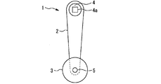
- FIG. 1 is a side view of a rope detachment preventing device according to Embodiment 1.
- FIG. 2 is a front view of the rope detachment preventing device according to the first embodiment.
- the rope detachment prevention device 1 includes a lever 2 and a contact member.
- a contact member for example, a roller 3 is provided.
- a mounting portion 4 is provided at one end of the lever 2.
- a mounting hole 4 a is formed in the mounting portion 4.
- the attachment hole 4a is formed in a quadrangle, for example.
- the attachment hole 4a is not formed in a circular shape, for example.
- the attachment portion 4 is attached to the lever 2 main body via a ratchet mechanism. That is, the attachment portion 4 can be rotated only in either the clockwise direction or the counterclockwise direction from the viewpoint of FIG.
- the roller 3 is rotatably supported on the other end of the lever 2.
- the rotating shaft 5 of the roller 3 is parallel to the central axis of the mounting hole 4a.
- the roller 3 is rotatable in both clockwise and counterclockwise directions in the viewpoint of FIG.
- FIG. 3 is a side view showing how to attach the rope detachment preventing device according to the first embodiment.
- FIG. 3 illustrates a case where the rope detachment prevention device 1 is attached to the cantilever-type hoisting machine 6.
- the hoisting machine 6 includes a base body 7 and a sheave 8.
- the base body 7 is a support body that supports the sheave 8.
- the sheave 8 is disposed so as to protrude forward of the base body 7.
- a plurality of ropes 9 are wound around the sheave 8.
- the rope 9 is wound around a rope groove formed in the sheave 8.
- the rope 9 is wound around the sheave 8 from above.
- a boss 10 is provided on the front surface of the base body 7.
- the boss 10 is positioned above the rotation shaft 11 of the sheave 8 in the vertical direction.
- the boss 10 is formed so that the shape in front view corresponds to the shape of the mounting hole 4a.
- the rope detachment prevention device 1 is attached to the base body 7 by fitting the boss 10 into the attachment hole 4a.
- the rotating shaft 5 of the roller 3 is positioned at the same height as the rotating shaft 11 of the sheave 8, for example.
- the central axis of the attachment hole 4 a and the boss 10 is parallel to the rotation axis 11 of the sheave 8.
- FIG. 4 is a side view of the sheave to which the rope disengagement device according to the first embodiment is attached.
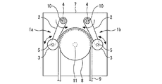
- FIG. 5 is a front view of the sheave to which the rope detachment preventing device according to Embodiment 1 is attached.
- the front end of the roller 3 is positioned forward of the rope 9 wound most forward in the sheave 8, for example.
- the rear end of the roller 3 is located behind the rope 9 wound most rearward in the sheave 8. That is, the width in the front-rear direction of the roller 3 is set to a size that allows the roller 3 to contact all of the plurality of ropes 9.
- two rope detachment prevention devices 1 are used for each sheave 8.
- at least two bosses 10 are provided on the front surface of the base body 7.
- the first rope detachment prevention device 1 a is attached to the left boss 10.
- the second rope detachment preventing device 1b is attached to the right boss 10.
- the left boss 10 is located, for example, between the left end of the outer peripheral surface of the sheave 8 and the rotating shaft 11 in the left-right direction.
- the right boss 10 is located, for example, between the right end portion of the outer peripheral surface of the sheave 8 and the rotary shaft 11 in the left-right direction.
- the two bosses 10 are arranged symmetrically with respect to a straight line passing through the rotation axis 11 in a front view.
- the second rope detachment prevention device 1b has the same appearance as the first rope detachment prevention device 1a, for example. However, the second rope detachment prevention device 1b is different from the first rope detachment prevention device 1a in the ratchet mechanism of the attachment portion 4.
- the mounting portion 4 of the first rope detachment preventing device 1a can be rotated only in the clockwise direction with respect to the lever 2 body from the viewpoint of FIG. That is, the lever 2 of the first rope release preventing device 1a can rotate only in the counterclockwise direction around the left boss 10 as an axis.
- the mounting portion 4 of the second rope detachment preventing device 1b can be rotated only in the counterclockwise direction with respect to the lever 2 main body from the viewpoint of FIG. That is, the lever 2 of the second rope detachment preventing device 1b can rotate only in the clockwise direction around the right boss 10 as an axis.
- the two rope detachment preventing devices 1 are provided so as to be rotatable only in the direction approaching the sheave 8.
- Each rope detachment prevention device 1 is always subjected to a force that rotates toward the sheave 8 by its own weight.
- the roller 3 of the first rope detachment prevention device 1a contacts the rope 9 at a position overlapping the left end portion of the outer peripheral surface of the sheave 8, for example.
- the roller 3 of the second rope detachment preventing device 1b contacts the rope 9 at a position overlapping with the right end portion of the outer peripheral surface of the sheave 8, for example. While the hoist 6 is driven and the rope 9 is moving, the two rope detachment preventing devices 1 are kept in contact with the rope 9 by the rotation of the roller 3.
- FIG. 6 is a side view of another sheave with the rope detachment preventing device according to the first embodiment attached thereto.
- FIG. 7 is a cross-sectional view of the rope detachment preventing device and the sheave shown in FIG.
- the hoisting machine includes a first bearing base 12 and a second bearing base 13 as a support for supporting the sheave 8.
- the rope detachment preventing device 1 is attached to the first bearing stand 12, for example.
- the lever 2 has one end attached to the support body of the sheave 8 and can rotate around an axis parallel to the rotation axis 11 of the sheave 8.
- the contact member is provided at the other end of the lever 2 and contacts the rope 9 wound around the sheave 8.
- One end of the lever 2 does not restrict the rotation of the lever 2 in a direction approaching the sheave 8 and does not restrict the rotation of the lever 2 in a direction away from the sheave 8 through a ratchet mechanism. Attached to the support. For this reason, even if the rope 9 is swayed by an earthquake or the like, the rope detachment preventing device 1 does not move away from the sheave 8, so the rope 9 does not come off.
- one end of the lever 2 is positioned above the rotary shaft 11 of the sheave 8 in the vertical direction, and is positioned between the rotary shaft 11 of the sheave 8 and the outer peripheral surface in the horizontal direction. For this reason, the rope detachment prevention device 1 rotates toward the sheave 8 by its own weight. As a result, it is possible to realize an elevator rope detachment prevention device that does not require adjustment work with a simple configuration.
- the contact member is, for example, a roller 3 that is rotatably supported on the other end of the lever 2.
- the roller 3 has a rotating shaft 5 parallel to the rotating shaft 11 of the sheave 8. In this case, the wear of the contact member that contacts the moving rope 9 can be reduced.
- the rotating shaft 5 of the roller 3 is located at the same height as the rotating shaft 11 of the sheave 8, for example.
- the rope 9 can be made as difficult to come off as possible without hindering the movement of the rope 9.
- the rope detachment prevention device 1 may be used for a sheave other than the sheave 8 of the hoisting machine. Also in this case, it is possible to prevent the rope from coming off without requiring adjustment work.
- This invention can be used for an elevator rope detachment prevention device that does not require adjustment work.
Landscapes
- Engineering & Computer Science (AREA)
- Civil Engineering (AREA)
- Mechanical Engineering (AREA)
- Structural Engineering (AREA)
- Lift-Guide Devices, And Elevator Ropes And Cables (AREA)
- Cage And Drive Apparatuses For Elevators (AREA)
Abstract
調整作業を必要としないエレベーターのロープ外れ止め装置を提供する。この発明に係るエレベーターのロープ外れ止め装置(1)は、綱車(8)の支持体に一端部が取り付けられ、綱車(8)の回転軸(11)に平行な軸を中心に回転可能なレバー(2)と、レバー(2)の他端部に設けられ、綱車(8)に巻き掛けられたロープ(9)に接触する接触部材と、を備え、レバー(2)の一端部は、レバー(2)が綱車(8)から離れる向きに回転することを規制するラチェット機構を介して綱車(8)の支持体に取り付けられるものである。
Description
この発明は、エレベーターのロープ外れ止め装置に関する。
ロープ式エレベーターには、綱車に巻き掛けられたロープが外れることを防止するために、ロープ外れ止め装置が設置される。特許文献1には、ロープ外れ止め装置が開示されている。
例えば、機械室なしタイプのロープ式エレベーターでは、昇降路の側壁、天井または障害物の付近に綱車が配置されることがある。この場合、ロープ外れ止め装置の調整作業に多大な時間および労力を要する。特許文献1に記載のロープ外れ止め装置によれば、調整作業が容易になり得るが、調整作業が不要になるわけではない。
この発明は、上記の課題を解決するためになされた。その目的は、調整作業を必要としないエレベーターのロープ外れ止め装置を提供することである。
この発明に係るエレベーターのロープ外れ止め装置は、綱車の支持体に一端部が取り付けられ、綱車の回転軸に平行な軸を中心に回転可能なレバーと、レバーの他端部に設けられ、綱車に巻き掛けられたロープに接触する接触部材と、を備え、レバーの一端部は、レバーが綱車から離れる向きに回転することを規制するラチェット機構を介して綱車の支持体に取り付けられるものである。
この発明によれば、レバーの一端部は、レバーが綱車から離れる向きに回転することを規制するラチェット機構を介して綱車の支持体に取り付けられる。このため、調整作業を必要としないエレベーターのロープ外れ止め装置を実現できる。
以下、添付の図面を参照して実施の形態について説明する。各図において、同一または相当する部分には同一の符号が付される。重複する説明は、適宜簡略化あるいは省略する。
実施の形態1.
図1は、実施の形態1におけるロープ外れ止め装置の側面図である。図2は、実施の形態1におけるロープ外れ止め装置の正面図である。
図1は、実施の形態1におけるロープ外れ止め装置の側面図である。図2は、実施の形態1におけるロープ外れ止め装置の正面図である。
ロープ外れ止め装置1は、レバー2および接触部材を備える。接触部材としては、例えば、ローラー3が設けられる。
レバー2の一端部には、取付部4が設けられる。取付部4には、取付穴4aが形成される。取付穴4aは、例えば、四角形に形成される。取付穴4aは、例えば、円形に形成されない。
取付部4は、レバー2本体に対してラチェット機構を介して取り付けられている。つまり、取付部4は、図2の視点において、時計回りまたは反時計回りのいずれか一方の向きにのみ回転可能である。
ローラー3は、レバー2の他端部に回転可能に支持される。ローラー3の回転軸5は、取付穴4aの中心軸に平行である。ローラー3は、図2の視点において、時計回りおよび反時計回りの両方の向きに回転可能である。
図3は、実施の形態1におけるロープ外れ止め装置の取り付け方を示す側面図である。
図3は、片持ち構造の巻上機6にロープ外れ止め装置1を取り付ける場合を例示する。
巻上機6は、基体7および綱車8を備える。基体7は、綱車8を支持する支持体である。綱車8は、基体7の前方に突出するように配置される。
綱車8には、複数のロープ9が巻き掛けられる。ロープ9は、綱車8に形成された綱溝に沿って巻き掛けられる。ロープ9は、例えば、綱車8に対して上側から巻き掛けられる。
基体7の前面には、ボス10が設けられる。ボス10は、上下方向において綱車8の回転軸11よりも上方に位置する。ボス10は、正面視における形状が取付穴4aの形状に対応するように形成される。
ロープ外れ止め装置1は、取付穴4aにボス10が嵌め込まれることで基体7に取り付けられる。ロープ外れ止め装置1が基体7に取り付けられた状態において、ローラー3の回転軸5は、例えば、綱車8の回転軸11と同じ高さに位置する。ロープ外れ止め装置1が基体7に取り付けられた状態において、取付穴4aおよびボス10の中心軸は、綱車8の回転軸11に平行である。
図4は、実施の形態1におけるロープ外れ止め装置が取り付けられた綱車の側面図である。図5は、実施の形態1におけるロープ外れ止め装置が取り付けられた綱車の正面図である。
図4および図5は、片持ち構造の巻上機6に2つのロープ外れ止め装置1が取り付けられた場合を例示する。
図4に示すように、ローラー3の前端は、例えば、綱車8において最も前側に巻き掛けられたロープ9よりも前方に位置する。ローラー3の後端は、例えば、綱車8において最も後側に巻き掛けられたロープ9よりも後方に位置する。つまり、ローラー3の前後方向における幅は、複数のロープ9の全てにローラー3が接触可能な大きさに設定される。
図5に示すように、1つの綱車8につき、例えば、2つのロープ外れ止め装置1が用いられる。この場合、基体7の前面には、少なくとも2つのボス10が設けられる。第1ロープ外れ止め装置1aは、左側のボス10に取り付けられる。第2ロープ外れ止め装置1bは、右側のボス10に取り付けられる。
左側のボス10は、例えば、左右方向において綱車8の外周面の左端部と回転軸11との間に位置する。右側のボス10は、例えば、左右方向において綱車8の外周面の右端部と回転軸11との間に位置する。2つのボス10は、例えば、正面視において回転軸11を通る直線を対称軸として左右対称に配置される。
第2ロープ外れ止め装置1bは、例えば、第1ロープ外れ止め装置1aと同じ外観を持つ。ただし、第2ロープ外れ止め装置1bは、取付部4のラチェット機構が第1ロープ外れ止め装置1aと異なる。
第1ロープ外れ止め装置1aの取付部4は、図5の視点において、レバー2本体に対して時計回りの向きにのみ回転可能である。つまり、第1ロープ外れ止め装置1aのレバー2は、左側のボス10を軸として反時計回りの向きにのみ回転可能である。
第2ロープ外れ止め装置1bの取付部4は、図5の視点において、レバー2本体に対して反時計回りの向きにのみ回転可能である。つまり、第2ロープ外れ止め装置1bのレバー2は、右側のボス10を軸として時計回りの向きにのみ回転可能である。
このように、2つのロープ外れ止め装置1は、綱車8に近づく向きにのみ回転可能に設けられる。それぞれのロープ外れ止め装置1には、自重により常に綱車8側へ回転する力が働く。
第1ロープ外れ止め装置1aのローラー3は、例えば、綱車8の外周面の左端部と重なる位置でロープ9に接触する。第2ロープ外れ止め装置1bのローラー3は、例えば、綱車8の外周面の右端部と重なる位置でロープ9に接触する。巻上機6が駆動してロープ9が動いている間も、ローラー3が回転することにより、2つのロープ外れ止め装置1はロープ9に接触した状態を維持する。
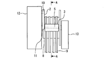
図6は、実施の形態1におけるロープ外れ止め装置が取り付けられた他の綱車の側面図である。図7は、図6に示すロープ外れ止め装置および綱車のA-A矢視断面図である。
図6および図7は、両持ち構造の巻上機に2つのロープ外れ止め装置1が取り付けられた場合を例示する。この場合、巻上機は、綱車8を支持する支持体として、第1軸受台12および第2軸受台13を備える。この場合、ロープ外れ止め装置1は、例えば、第1軸受台12に対して取り付けられる。
以上で説明した実施の形態1によれば、レバー2は、綱車8の支持体に一端部が取り付けられ、綱車8の回転軸11に平行な軸を中心に回転可能である。接触部材は、レバー2の他端部に設けられ、綱車8に巻き掛けられたロープ9に接触する。レバー2の一端部は、レバー2が綱車8に近づく向きに回転することを規制せず、レバー2が綱車8から離れる向きに回転することを規制するラチェット機構を介して綱車8の支持体に取り付けられる。このため、地震等によりロープ9が揺れたとしても、ロープ外れ止め装置1は綱車8から離れる向きには移動しないため、ロープ9が外れることはない。また、綱車8の綱溝が摩耗しても、ロープ外れ止め装置1は綱車8側へ回転するため、常にロープ9と接触した状態になる。その結果、調整作業を必要としないエレベーターのロープ外れ止め装置を実現できる。
また、レバー2の一端部は、上下方向において綱車8の回転軸11よりも上方に位置し、水平方向において綱車8の回転軸11と外周面との間に位置する。このため、ロープ外れ止め装置1は、自重により綱車8側へ回転する。その結果、簡単な構成で、調整作業を必要としないエレベーターのロープ外れ止め装置を実現できる。
また、接触部材は、例えば、レバー2の他端部に回転可能に支持されたローラー3である。ローラー3は、綱車8の回転軸11に平行な回転軸5を有する。この場合、移動するロープ9と接触する接触部材の摩耗を軽減できる。
また、ローラー3の回転軸5は、例えば、綱車8の回転軸11と同じ高さに位置する。この場合、ロープ9の移動を妨げることなく、可能な限りロープ9を外れ難くすることができる。
なお、ロープ外れ止め装置1は、巻上機の綱車8以外の綱車に使用してもよい。この場合も、調整作業を必要とせずにロープ外れを防止することができる。
この発明は、調整作業を必要としないエレベーターのロープ外れ止め装置に利用できる。
1 ロープ外れ止め装置
1a 第1ロープ外れ止め装置
1b 第2ロープ外れ止め装置
2 レバー
3 ローラー
4 取付部
4a 取付穴
5 回転軸
6 巻上機
7 基体
8 綱車
9 ロープ
10 ボス
11 回転軸
12 第1軸受台
13 第2軸受台
1a 第1ロープ外れ止め装置
1b 第2ロープ外れ止め装置
2 レバー
3 ローラー
4 取付部
4a 取付穴
5 回転軸
6 巻上機
7 基体
8 綱車
9 ロープ
10 ボス
11 回転軸
12 第1軸受台
13 第2軸受台
Claims (4)
- 綱車の支持体に一端部が取り付けられ、前記綱車の回転軸に平行な軸を中心に回転可能なレバーと、
前記レバーの他端部に設けられ、前記綱車に巻き掛けられたロープに接触する接触部材と、
を備え、
前記レバーの一端部は、前記レバーが前記綱車から離れる向きに回転することを規制するラチェット機構を介して前記綱車の支持体に取り付けられるエレベーターのロープ外れ止め装置。 - 前記レバーの一端部は、上下方向において前記綱車の回転軸よりも上方に位置し、水平方向において前記綱車の回転軸と外周面との間に位置する請求項1に記載のエレベーターのロープ外れ止め装置。
- 前記接触部材は、前記レバーの他端部に回転可能に支持されたローラーである請求項1または請求項2に記載のエレベーターのロープ外れ止め装置。
- 前記ローラーの回転軸は、前記綱車の回転軸と同じ高さに位置する請求項3に記載のエレベーターのロープ外れ止め装置。
Priority Applications (2)
| Application Number | Priority Date | Filing Date | Title |
|---|---|---|---|
| JP2020518860A JP6908187B2 (ja) | 2018-05-15 | 2018-05-15 | エレベーターのロープ外れ止め装置 |
| PCT/JP2018/018791 WO2019220546A1 (ja) | 2018-05-15 | 2018-05-15 | エレベーターのロープ外れ止め装置 |
Applications Claiming Priority (1)
| Application Number | Priority Date | Filing Date | Title |
|---|---|---|---|
| PCT/JP2018/018791 WO2019220546A1 (ja) | 2018-05-15 | 2018-05-15 | エレベーターのロープ外れ止め装置 |
Publications (1)
| Publication Number | Publication Date |
|---|---|
| WO2019220546A1 true WO2019220546A1 (ja) | 2019-11-21 |
Family
ID=68539791
Family Applications (1)
| Application Number | Title | Priority Date | Filing Date |
|---|---|---|---|
| PCT/JP2018/018791 Ceased WO2019220546A1 (ja) | 2018-05-15 | 2018-05-15 | エレベーターのロープ外れ止め装置 |
Country Status (2)
| Country | Link |
|---|---|
| JP (1) | JP6908187B2 (ja) |
| WO (1) | WO2019220546A1 (ja) |
Cited By (2)
| Publication number | Priority date | Publication date | Assignee | Title |
|---|---|---|---|---|
| JPWO2023233592A1 (ja) * | 2022-06-01 | 2023-12-07 | ||
| JP7455264B1 (ja) | 2023-08-22 | 2024-03-25 | 三菱電機ビルソリューションズ株式会社 | エレベーターのロープ外れ止め装置 |
Citations (6)
| Publication number | Priority date | Publication date | Assignee | Title |
|---|---|---|---|---|
| US4620615A (en) * | 1985-11-14 | 1986-11-04 | Westinghouse Electric Corp. | Elevator system |
| JPH0266092A (ja) * | 1988-09-01 | 1990-03-06 | Hitachi Elevator Eng & Service Co Ltd | エレベータの主ロープの駆動方法 |
| JP2002003119A (ja) * | 2000-06-27 | 2002-01-09 | Toshiba Corp | ロープ異常検出装置及び同装置を備えたエレベーター制御装置 |
| JP2003276972A (ja) * | 2002-03-22 | 2003-10-02 | Mitsubishi Electric Corp | エレベーター用巻上機 |
| JP2007131379A (ja) * | 2005-11-09 | 2007-05-31 | Mitsubishi Electric Corp | エレベータ用主索外れ止め装置及びその据付・保守点検方法 |
| JP2016003101A (ja) * | 2014-06-17 | 2016-01-12 | 三菱電機ビルテクノサービス株式会社 | 異物挟み検出装置 |
Family Cites Families (1)
| Publication number | Priority date | Publication date | Assignee | Title |
|---|---|---|---|---|
| JP2012153507A (ja) * | 2011-01-27 | 2012-08-16 | Toshiba Elevator Co Ltd | エレベータおよびエレベータの非常時運転方法 |
-
2018
- 2018-05-15 WO PCT/JP2018/018791 patent/WO2019220546A1/ja not_active Ceased
- 2018-05-15 JP JP2020518860A patent/JP6908187B2/ja active Active
Patent Citations (6)
| Publication number | Priority date | Publication date | Assignee | Title |
|---|---|---|---|---|
| US4620615A (en) * | 1985-11-14 | 1986-11-04 | Westinghouse Electric Corp. | Elevator system |
| JPH0266092A (ja) * | 1988-09-01 | 1990-03-06 | Hitachi Elevator Eng & Service Co Ltd | エレベータの主ロープの駆動方法 |
| JP2002003119A (ja) * | 2000-06-27 | 2002-01-09 | Toshiba Corp | ロープ異常検出装置及び同装置を備えたエレベーター制御装置 |
| JP2003276972A (ja) * | 2002-03-22 | 2003-10-02 | Mitsubishi Electric Corp | エレベーター用巻上機 |
| JP2007131379A (ja) * | 2005-11-09 | 2007-05-31 | Mitsubishi Electric Corp | エレベータ用主索外れ止め装置及びその据付・保守点検方法 |
| JP2016003101A (ja) * | 2014-06-17 | 2016-01-12 | 三菱電機ビルテクノサービス株式会社 | 異物挟み検出装置 |
Cited By (5)
| Publication number | Priority date | Publication date | Assignee | Title |
|---|---|---|---|---|
| JPWO2023233592A1 (ja) * | 2022-06-01 | 2023-12-07 | ||
| WO2023233592A1 (ja) * | 2022-06-01 | 2023-12-07 | 三菱電機株式会社 | エレベータ装置 |
| JP7763338B2 (ja) | 2022-06-01 | 2025-10-31 | 三菱電機株式会社 | エレベータ装置 |
| JP7455264B1 (ja) | 2023-08-22 | 2024-03-25 | 三菱電機ビルソリューションズ株式会社 | エレベーターのロープ外れ止め装置 |
| JP2025029634A (ja) * | 2023-08-22 | 2025-03-07 | 三菱電機ビルソリューションズ株式会社 | エレベーターのロープ外れ止め装置 |
Also Published As
| Publication number | Publication date |
|---|---|
| JP6908187B2 (ja) | 2021-07-21 |
| JPWO2019220546A1 (ja) | 2020-10-22 |
Similar Documents
| Publication | Publication Date | Title |
|---|---|---|
| WO2019220546A1 (ja) | エレベーターのロープ外れ止め装置 | |
| CN102272030B (zh) | 设置有锁定设备的电梯和防止电梯轿厢运动的锁定设备 | |
| KR20150087041A (ko) | 케이블 드럼 풀림대 기구 | |
| JP2010168147A (ja) | ロープ外れ止め装置 | |
| US5368124A (en) | Device suspending a working cage | |
| JP6232205B2 (ja) | エレベーター装置 | |
| JP6435281B2 (ja) | 電動ホイスト | |
| JP4861996B2 (ja) | 角度を形成するアンダースラング式ローピング配置を有するエレベータかご | |
| JP6932261B2 (ja) | エレベータの調速機 | |
| JP2008247586A (ja) | ダブルデッキクレーンの旋回用リミットスイッチ装置 | |
| JP6525363B2 (ja) | エレベータ制動装置 | |
| JP5135396B2 (ja) | エレベータ用調速機 | |
| JP5385601B2 (ja) | クレーン | |
| JP6686264B2 (ja) | 電動ホイスト | |
| US484038A (en) | Fourths to | |
| JP2006096506A (ja) | クレーン | |
| JP4536663B2 (ja) | エレベータ巻上機用ブレーキ装置 | |
| JP2000281277A (ja) | 建設機械のキャビン取付装置 | |
| JP2003073079A (ja) | ロープウインチ | |
| JP6721005B2 (ja) | クレーン | |
| JP6658997B1 (ja) | エレベーターのブレーキ装置 | |
| JP4901146B2 (ja) | エレベータ | |
| JP6281710B2 (ja) | 取鍋の復転防止用ストッパー | |
| JP2024075396A (ja) | 作業機械 | |
| JP6295999B2 (ja) | ブーム先端構造 |
Legal Events
| Date | Code | Title | Description |
|---|---|---|---|
| 121 | Ep: the epo has been informed by wipo that ep was designated in this application |
Ref document number: 18919097 Country of ref document: EP Kind code of ref document: A1 |
|
| ENP | Entry into the national phase |
Ref document number: 2020518860 Country of ref document: JP Kind code of ref document: A |
|
| NENP | Non-entry into the national phase |
Ref country code: DE |
|
| 122 | Ep: pct application non-entry in european phase |
Ref document number: 18919097 Country of ref document: EP Kind code of ref document: A1 |