WO2019208140A1 - 導体、アンテナ、および通信装置 - Google Patents
導体、アンテナ、および通信装置 Download PDFInfo
- Publication number
- WO2019208140A1 WO2019208140A1 PCT/JP2019/014856 JP2019014856W WO2019208140A1 WO 2019208140 A1 WO2019208140 A1 WO 2019208140A1 JP 2019014856 W JP2019014856 W JP 2019014856W WO 2019208140 A1 WO2019208140 A1 WO 2019208140A1
- Authority
- WO
- WIPO (PCT)
- Prior art keywords
- conductor
- opening
- split ring
- present disclosure
- ring resonator
- Prior art date
- Legal status (The legal status is an assumption and is not a legal conclusion. Google has not performed a legal analysis and makes no representation as to the accuracy of the status listed.)
- Ceased
Links
Images











Classifications
-
- H—ELECTRICITY
- H01—ELECTRIC ELEMENTS
- H01Q—ANTENNAS, i.e. RADIO AERIALS
- H01Q13/00—Waveguide horns or mouths; Slot antennas; Leaky-waveguide antennas; Equivalent structures causing radiation along the transmission path of a guided wave
- H01Q13/10—Resonant slot antennas
-
- H—ELECTRICITY
- H01—ELECTRIC ELEMENTS
- H01Q—ANTENNAS, i.e. RADIO AERIALS
- H01Q15/00—Devices for reflection, refraction, diffraction or polarisation of waves radiated from an antenna, e.g. quasi-optical devices
- H01Q15/0006—Devices acting selectively as reflecting surface, as diffracting or as refracting device, e.g. frequency filtering or angular spatial filtering devices
- H01Q15/0086—Devices acting selectively as reflecting surface, as diffracting or as refracting device, e.g. frequency filtering or angular spatial filtering devices said selective devices having materials with a synthesized negative refractive index, e.g. metamaterials or left-handed materials
-
- H—ELECTRICITY
- H01—ELECTRIC ELEMENTS
- H01Q—ANTENNAS, i.e. RADIO AERIALS
- H01Q1/00—Details of, or arrangements associated with, antennas
- H01Q1/36—Structural form of radiating elements, e.g. cone, spiral, umbrella; Particular materials used therewith
- H01Q1/38—Structural form of radiating elements, e.g. cone, spiral, umbrella; Particular materials used therewith formed by a conductive layer on an insulating support
-
- H—ELECTRICITY
- H01—ELECTRIC ELEMENTS
- H01Q—ANTENNAS, i.e. RADIO AERIALS
- H01Q13/00—Waveguide horns or mouths; Slot antennas; Leaky-waveguide antennas; Equivalent structures causing radiation along the transmission path of a guided wave
- H01Q13/10—Resonant slot antennas
- H01Q13/16—Folded slot antennas
-
- H—ELECTRICITY
- H01—ELECTRIC ELEMENTS
- H01Q—ANTENNAS, i.e. RADIO AERIALS
- H01Q3/00—Arrangements for changing or varying the orientation or the shape of the directional pattern of the waves radiated from an antenna or antenna system
- H01Q3/01—Arrangements for changing or varying the orientation or the shape of the directional pattern of the waves radiated from an antenna or antenna system varying the shape of the antenna or antenna system
-
- H—ELECTRICITY
- H01—ELECTRIC ELEMENTS
- H01Q—ANTENNAS, i.e. RADIO AERIALS
- H01Q9/00—Electrically-short antennas having dimensions not more than twice the operating wavelength and consisting of conductive active radiating elements
- H01Q9/04—Resonant antennas
- H01Q9/0407—Substantially flat resonant element parallel to ground plane, e.g. patch antenna
Definitions
- the present invention relates to, for example, a conductor, an antenna, and a communication device.
- Patent Document 1 discloses a communication apparatus including an antenna configured with a split ring resonator.
- the conductor according to an aspect of the present disclosure may include a split ring resonator and an opening, and the split in the split ring resonator and the opening may be spatially continuous.
- a split ring resonator can be disposed in addition to the end of the conductor.
- Plan view of example conductor according to certain aspects of the present disclosure Plan view of example conductor according to certain aspects of the present disclosure
- Plan view of example conductor according to certain aspects of the present disclosure A perspective view of an example of a conductor according to an aspect of the present disclosure.
- Examples of currents in example conductors according to certain aspects of the present disclosure Plan view of example conductor according to certain aspects of the present disclosure
- Plan view of example conductor according to certain aspects of the present disclosure Plan view of example conductor according to certain aspects of the present disclosure
- plan view of example conductor according to certain aspects of the present disclosure Plan view of example conductor according to certain aspects of the present disclosure
- Examples of return loss characteristics of example split ring resonators according to certain aspects of the present disclosure Plan view of example conductor according to certain aspects of the present disclosure
- Plan view of example conductor according to certain aspects of the present disclosure Plan view of example conductor according to certain aspects of the present disclosure
- Plan view of example conductor according to certain aspects of the present disclosure Plan view of example conductor according to certain aspects of the present disclosure
- Plan view of example conductor according to certain aspects of the present disclosure Plan view of example conductor according to certain aspects of the present disclosure
- An exploded view of an example implementation of a componentized split ring resonator according to certain aspects of the present disclosure Side view of an example implementation of a componentized split ring resonator according to certain aspects of the present disclosure
- the conductor 1 includes the split ring resonator 12 and the opening 13, and the split 121 and the opening 13 in the split ring resonator 12 are spatially continuous. Good.
- FIG. 1 is a plan view of an example of a conductor 1 according to an aspect of the present disclosure.
- FIG. 2 is a plan view of an example of the conductor 1 according to an aspect of the present disclosure.
- the center of the ring in the split ring resonator 12 is referred to as a point C.
- a line segment connecting the split in the split ring resonator 12 and the point C is referred to as a line segment m.
- a straight line obtained by extending the line segment m is referred to as a straight line M.
- a straight line that is orthogonal to the straight line M and passes through the point C is referred to as a straight line L. That is, the point C exists on the straight line L.
- the direction in which the straight line M extends is referred to as the Y-axis direction.
- the direction in which the straight line L extends is referred to as the X-axis direction.
- the conductor 1 may be formed of a conductive pattern, sheet metal, or the like.
- the split ring resonator 12 may include a split 121, a split ring 122, and an in-ring opening 123.
- the split ring 122 includes a first conductor 1221 extending in the X-axis direction across the split 121, a second conductor 1222 extending in the X-axis direction, a third conductor 1223 extending in the Y-axis direction, and extending in the Y-axis direction.
- the shape based on the substantially C shape along the square ring provided with the 4th conductor 1224 may be sufficient.
- the split ring 122 may have any shape, for example, a shape based on shapes along various other rings such as a circular ring, an elliptical ring, a track ring, and the like.
- the portion of the first conductor 1221 sandwiching the split 121 may or may not be extended in the Y-axis direction.
- the ring opening 123 may be surrounded by the split 121 and the split ring 122.
- the opening 13 may be adjacent to the split 121 and the first conductor 1221.
- the length of the opening 13 in the X-axis direction may be longer than the length of the split 121 in the X-axis direction.
- the opening 13 may have any shape, for example, a polygon such as a square or a rectangle, or a circle or an ellipse.
- the feed line 2 may be connected to the conductor 1.
- the first end of the feeder line 2 may be connected to the conductor 1.
- the first end of the feeder line 2 may be connected to the split ring 122.
- the first end of the feeder line 2 may be connected to the first conductor 1221.
- the second end of the feeder line 2 may be extended across the ring opening 123 and the second conductor 1222 as viewed from the first end of the feeder line 2.
- the power supply line 2 may be an electric wire that supplies an RF (Radio Frequency) signal.
- an RF signal may be given to the second end of the feeder line 2.
- the power supply line 2 may be formed of a lead wire, a sheet metal, or the like.
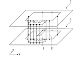
- FIG. 3 is a perspective view of an example of a conductor according to an aspect of the present disclosure.
- the conductor 1 may be provided on one of the two plate surfaces of the substrate 3.
- the substrate 3 may be a glass epoxy substrate, a ceramic substrate, a resin substrate, a glass substrate, or the like.
- the power supply line 2 may be connected to the first conductor 1221 via the via 21 penetrating between both plate surfaces of the substrate 3.
- the feeder line 2 may be provided on the plate surface of the substrate 3 on which the conductor 1 is not provided.
- FIG. 4 is an exploded view of an example of a conductor according to an aspect of the present disclosure.
- the conductor 1 may have a single layer configuration or a multilayer configuration.
- the conductor 1 when the conductor 1 has a two-layer configuration, the conductor 1 is provided in the first layer L1 with respect to the layers that are laminated in the order of the first layer L1, the second layer L2, and the third layer L3.
- the conductor 1 may be provided, and the feed line 2 may be provided in the second layer L2.
- the conductor 1 in the first layer L ⁇ b> 1, the conductor 1 in the third layer L ⁇ b> 3, and the feeder line 2 may be connected via the vias 21.
- FIG. 5 is a perspective view of an example of a conductor according to an aspect of the present disclosure.
- the conductor 1 may have a cylindrical shape in which the X-axis direction is the cylindrical axis direction D.
- the conductor 1 may be connected to the connector 4 on one end side in the cylindrical axis direction D.
- the connector 4 may include an outer peripheral conductor 41 and an inner shaft conductor 42.
- one end side in the cylindrical axis direction D of the conductor 1 may be connected to the outer peripheral conductor 41, and the first conductor 1221 may be connected to the inner shaft conductor 42 via the feeder line 2.
- one end side in the cylindrical axis direction D of the conductor 1 may be directly connected to the outer peripheral conductor 41 or may be connected via a lead wire, a sheet metal, or the like.
- FIG. 6 is an example of current in an example of a conductor according to an aspect of the present disclosure.
- the conductor 1 includes the split ring resonator 12 and the opening 13, and the split 121 and the opening 13 in the split ring resonator 12 are spatially separated. It may be continuous.
- the conductor 1 can generate the current I1 in the X-axis direction around the split 121 and the split 121, the current I2 along the opening 123 in the ring, and the like. Can be radiated efficiently.
- a split ring resonator can be arranged in addition to the end of the conductor.
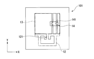
- a conductor according to an aspect of the present disclosure may include the control unit 14, and the control unit 14 may be configured to control the size of the opening 13.
- FIG. 7 is a plan view of an example of a conductor according to an aspect of the present disclosure.
- control unit 14 may include a switch 141. At that time, by turning the switch 141 on and off, the conductor 101 may be electrically opened or short-circuited at the positions aligned in the Y-axis direction with the opening 13 interposed therebetween.
- the conductive pattern may extend from the periphery of the opening 13 toward the switch 141.
- the number of switches 141 may be one, or three or more.
- the control means 14 shown in FIG. 7 short-circuits the positions aligned in the Y-axis direction, if the control means 14 is configured to control the size of the opening 13, the control means 14 determines which positions. You may short-circuit.
- the control means 14 may short-circuit the conductor 101 at positions aligned in the X-axis direction.
- the control means 14 shown in FIG. 7 short-circuits the conductor 101, the control means 14 may connect the conductor 101 in any way as long as it is configured to control the size of the opening 13.
- the control means 14 may electrically connect the conductors 101 via impedance elements at positions aligned in the Y-axis direction with the opening 13 in between.
- the switch 141 is shown as the control means 14, but any means may be provided as long as it is configured to control the size of the opening 13.
- a jumper line may be provided between the positions of the conductor 101 that sandwich the opening 13 as the control means 14.
- the size of the opening 13 may be controlled by a jumper wire short-circuiting the conductor 101.
- a short-circuit pattern may be provided in advance between positions in the conductor 101 that sandwich the opening 13. At that time, the size of the opening 13 may be controlled by cutting the short-circuit pattern.
- the control unit 14 since the control unit 14 is configured to control the size of the opening 13, the frequency characteristics of the split ring resonator 12 can be controlled.
- a current is generated not only in the current I1 and the current I2 but also around the opening 13 in the conductor 101. These currents affect the frequency characteristics of the split ring resonator 12. For this reason, if the size of the opening 13 is controlled, the frequency characteristic of the split ring resonator 12 can be controlled. If the frequency characteristic of the split ring resonator 12 can be controlled, the frequency characteristic of the reflection loss of the split ring resonator 12 can be controlled. For example, when the split ring resonator 12 is applied to a radiating antenna, the conductor 101 is The radiation characteristics of the split ring resonator 12 can be controlled.
- a conductor according to an aspect of the present disclosure may have an elongated shape in the opening 13.
- FIG. 8 is a plan view of an example of a conductor according to an aspect of the present disclosure.
- the opening 13 may have an elongated shape in the X-axis direction compared to the Y-axis direction.
- the opening 13 is elongated in the X-axis direction, but may be elongated in any direction.
- the opening 13 may be elongated in the Y-axis direction, or may be elongated in an oblique manner with respect to the X-axis direction.
- the opening 13 may be further elongated in the Y-axis direction from one end elongated in the X-axis direction.
- the opening 13 may be further elongated in the X-axis direction from one end elongated in the Y-axis direction.
- the opening 13 may be further branched and elongated from one end that is elongated.
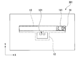
- FIG. 9 is a plan view of an example of a conductor according to an aspect of the present disclosure.
- the conductor 201 may include control means 14 configured to control the size of the opening 13.
- the conductor 201 since the opening 13 has an elongated shape, the conductor 201 can easily secure a space for placing other components around the opening 13.
- the opening 13 since the current generated around the opening 13 affects the frequency characteristics of the split ring resonator 12, the opening 13 needs to have a certain outer peripheral length. For example, when an elongated opening having the same outer peripheral length is compared with a square opening, the area of the elongated opening is smaller than the area of the square opening. For this reason, the area which the opening 13 in the conductor 201 occupies can be reduced by using a narrower shape than a square. Therefore, by forming the opening 13 in an elongated shape, the conductor 201 can easily secure a space for placing other components around the opening 13.
- the conductor according to an aspect of the present disclosure (for example, the conductor 201) has a length in the opening 13 in a direction substantially parallel to the tangent line between the split ring resonator 12 and the opening 13 and the split ring in the opening 13. It may be longer than the length in the direction substantially perpendicular to the tangent line between the resonator 12 and the opening 13.
- FIG. 10 is a plan view of an example of a conductor according to an aspect of the present disclosure.
- a direction substantially parallel to the tangent line between the split ring resonator 12 and the opening 13 in the opening 13 corresponds to the X-axis direction
- a direction substantially perpendicular to the tangent line between the split ring resonator 12 and the opening 13 in the opening 13. May correspond to the Y-axis direction.
- the length of the opening 13 in the X-axis direction may be longer than the length of the opening 13 in the Y-axis direction.
- the opening 13 may have an elongated shape that extends longer than the split ring resonator 12 in the X-axis direction.
- the opening 13 may have an elongated shape that extends longer from the split ring resonator 12 to both sides in the X-axis direction.
- FIG. 11 is a plan view of an example of a conductor according to an aspect of the present disclosure.
- the conductor 301 may comprise control means 14 configured to control the size of the opening 13.
- the control unit 14 may include a switch 141.
- the conductor 301 may be electrically opened or short-circuited at positions aligned in the Y-axis direction with the opening 13 interposed therebetween by turning the switch 141 on and off.
- FIG. 12 is a perspective view of an example of a conductor according to an aspect of the present disclosure.
- the conductor 301 may have a cylindrical shape in which the X-axis direction is the cylindrical axis direction D.
- the conductor 301 may be connected to the connector 4 on one end side in the cylindrical axis direction D.
- the connector 4 may include an outer peripheral conductor 41 and an inner shaft conductor 42.
- one end side in the cylindrical axis direction D of the conductor 301 may be connected to the outer peripheral conductor 41, and the first conductor 1221 may be connected to the inner shaft conductor 42 via the feeder line 2.
- one end side of the conductor 301 in the cylindrical axis direction D may be directly connected to the outer conductor 41 or may be connected via a lead wire, a sheet metal, or the like.
- the length of the opening 13 in the direction substantially parallel to the tangent line between the split ring resonator 12 and the opening 13 is long. Easy to secure space to put the parts.
- the length of the opening 13 in the direction substantially parallel to the tangent line between the split ring resonator 12 and the opening 13 needs to have a certain length. . For example, when comparing an opening with an elongated shape and a square opening with the same length in the direction substantially parallel to the tangent line between the split ring resonator and the opening, the shape of the opening is smaller than the area of the square opening.
- the area of the opening is smaller. For this reason, the area which the opening in a conductor occupies can be made small by using the shape of elongate rather than making it square. Therefore, by making the opening 13 into an elongated shape having a long length in the direction substantially parallel to the tangent line between the split ring resonator 12 and the opening 13 in the opening 13, the conductor 301 has other parts around the opening 13. Easy to secure space for putting.
- a conductor according to an aspect of the present disclosure (for example, the conductor 201) has a split ring whose opening 13 has a length in a direction substantially parallel to the tangent line between the split ring resonator 12 and the opening 13. It may be shorter than the length in the direction substantially perpendicular to the tangent line between the resonator 12 and the opening 13.
- FIG. 13 is a plan view of an example of a conductor according to an aspect of the present disclosure.
- the length of the opening 13 in the X-axis direction may be shorter than the length of the opening 13 in the Y-axis direction.
- the opening 13 may have an elongated shape extending in the Y-axis direction from the split ring resonator 12.
- the opening 13 may have an elongated shape extending in the Y-axis direction from the outer periphery of both sides of the split 121 in the X-axis direction.
- FIG. 14 is a plan view of an example of a conductor according to an aspect of the present disclosure.
- the conductor 401 may include control means 14 configured to control the size of the opening 13.
- FIG. 15 is an example of reflection loss characteristics of an example of a split ring resonator according to an aspect of the present disclosure.
- a curve a is a reflection loss curve of the split ring resonator 12 in the conductor 301 according to FIG.
- a curve b is a reflection loss curve of the split ring resonator 12 in the conductor 401 according to FIG.
- the reflection loss curve of the split ring resonator 12 when the opening 13 is not provided in the conductor and the split ring resonator 12 is disposed at the end of the conductor is shown.
- the reflection loss at the resonance frequency of each split ring resonator 12 near the frequency fo is smaller for the curve b than for the curve a.
- the reflection loss characteristic in the curve b is close to the reflection loss characteristic of the comparative example in which the split ring resonator 12 is disposed at the end of the conductor. That is, according to the conductor 401 according to an aspect of the present disclosure, since the length of the opening 13 in the direction substantially parallel to the tangent line between the split ring resonator 12 and the opening 13 is short, the conductor 401 has a reflection loss characteristic. It can be made smaller. As shown in FIG. 15, the resonance frequency is different between the curve a and the curve b. Specifically, the resonance frequency of curve b is smaller than the resonance frequency of curve a.
- the resonance frequency of the split ring resonator 12 can also be controlled by adjusting the relationship.
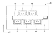
- a conductor according to an aspect of the present disclosure may include a plurality of split ring resonators 12.
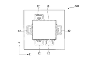
- FIG. 16 is a plan view of an example of a conductor according to an aspect of the present disclosure.
- the plurality of split ring resonators 12 may share the opening 13.
- five split ring resonators 12 may be provided as a plurality of split ring resonators 12 with respect to one opening 13.
- the five split ring resonators 12 may be provided so as to surround the opening 13.
- FIG. 17 is a plan view of an example of a conductor according to an aspect of the present disclosure.
- the plurality of split ring resonators 12 may be disposed so as to sandwich the opening 13 from both sides in the Y direction.
- FIG. 18 is a plan view of an example of a conductor according to an aspect of the present disclosure.
- the plurality of split ring resonators 12 may be arranged so as to sandwich the opening 13 from both sides in the Y-axis direction.
- FIG. 19 is a plan view of an example of a conductor according to an aspect of the present disclosure.
- FIG. 20 is a plan view of an example of a conductor according to an aspect of the present disclosure.
- FIG. 21 is a plan view of an example of a conductor according to an aspect of the present disclosure.
- each conductor 501 may further include control means 14 configured to control the size of the opening 13.
- a conductor 501 according to an aspect of the present disclosure includes a plurality of split ring resonators 12.
- the opening 13 can be shared between the plurality of split ring resonators 12. For this reason, the area occupied by the opening 13 in the conductor 501 can be reduced. Therefore, the conductor 501 can easily secure a space for placing other components.
- all of the plurality of split ring resonators 12 share one opening 13, but at least two split rings among the plurality of split ring resonators 12 are used.
- the resonator 12 may share one opening 13.
- a conductor according to a disclosure of the present disclosure can be used for an antenna.
- an antenna according to an aspect of the present disclosure may include a conductor according to an aspect of the present disclosure (for example, the conductor 1, the conductor 101, the conductor 201, the conductor 301, the conductor 401, the conductor 501, and the like).
- an antenna including a conductor according to a disclosure of the present disclosure can be used for a communication device.
- a communication device includes an antenna including conductors (for example, the conductor 1, the conductor 101, the conductor 201, the conductor 301, the conductor 401, the conductor 501, and the like) according to an aspect of the present disclosure. Also good.
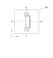
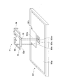
- FIG. 22 and FIG. 23 are mounting examples of the split-ring resonator formed as a component according to an aspect of the present disclosure.
- the split ring resonator 91 in FIGS. 22 and 23 may include a split ring portion 92, a power supply terminal 93, and a ground terminal 94.
- the split ring resonator 91 in FIGS. 22 and 23 may be formed of sheet metal as illustrated.
- the power supply terminal 93 in FIGS. 22 and 23 may be a terminal for supplying an RF signal to the split ring portion 92.
- the circuit board 901 in FIGS. 22 and 23 may be separated from the ground pattern 901g on the circuit board 901 on which circuit elements such as transmission / reception ICs and amplifiers are mounted.
- the circuit board 901 in FIGS. 22 and 23 includes a gap 901 a from which a ground pattern 901 g is cut according to the shape and dimensions of the split ring resonator 91, and a receiving terminal 901 r that is a terminal connected to the ground terminal 94. You may prepare.
- the split ring resonator 91 in FIGS. 22 and 23 can be handled as a component separated from the circuit board 901 by including the ground terminal 94, for example.
- the antenna may be formed as a whole.
- the receiving terminal 901r and the ground terminal 94 are inserted into the receiving terminal 901r in which the receiving terminal 901r is a hole formed in the circuit board and the ground terminal 94 is a hole, respectively. It may be.
- the ground terminal 94 is inserted and connected to the receiving terminal 901r, it is electrically connected and fixed via solder or the like.
- a part of the split ring portion 92 may include a support 92a that is bent and extended in the direction of the circuit board 901.
- the support 92a allows the split ring resonator 91 to be balanced with a certain clearance from the surface of the circuit board 901, thereby reducing the influence of the circuit board on the characteristics of the split ring resonator.
- the support 92a may be electrically connected to or disconnected from the ground pattern 901g.
- the power supply terminal 93 may also be inserted into the receiving terminal 901sr formed as a hole in the circuit board and connected to the receiving terminal 901sr.
- the receiving terminal 901sr is formed in the region of the power feeding pattern 901s on the circuit board, and when the power feeding terminal 93 and the receiving terminal 901sr are connected, the power feeding terminal 93 and the power feeding pattern 901s are electrically connected by solder or the like, and Fixed.
Landscapes
- Control Of Motors That Do Not Use Commutators (AREA)
- Waveguide Aerials (AREA)
- Input Circuits Of Receivers And Coupling Of Receivers And Audio Equipment (AREA)
- Burglar Alarm Systems (AREA)
Priority Applications (5)
| Application Number | Priority Date | Filing Date | Title |
|---|---|---|---|
| CN201980027890.6A CN112204816B (zh) | 2018-04-27 | 2019-04-03 | 导体、天线和通信装置 |
| EP19793197.5A EP3780278B1 (en) | 2018-04-27 | 2019-04-03 | Conductor, antenna, and communication device |
| JP2020516166A JP7265539B2 (ja) | 2018-04-27 | 2019-04-03 | 導体、アンテナ、および通信装置 |
| US17/050,487 US11545755B2 (en) | 2018-04-27 | 2019-04-03 | Conductor, antenna, and communication device |
| KR1020207030850A KR102407581B1 (ko) | 2018-04-27 | 2019-04-03 | 도체, 안테나 및 통신장치 |
Applications Claiming Priority (2)
| Application Number | Priority Date | Filing Date | Title |
|---|---|---|---|
| JP2018-087690 | 2018-04-27 | ||
| JP2018087690 | 2018-04-27 |
Publications (1)
| Publication Number | Publication Date |
|---|---|
| WO2019208140A1 true WO2019208140A1 (ja) | 2019-10-31 |
Family
ID=68294006
Family Applications (1)
| Application Number | Title | Priority Date | Filing Date |
|---|---|---|---|
| PCT/JP2019/014856 Ceased WO2019208140A1 (ja) | 2018-04-27 | 2019-04-03 | 導体、アンテナ、および通信装置 |
Country Status (7)
| Country | Link |
|---|---|
| US (1) | US11545755B2 (https=) |
| EP (1) | EP3780278B1 (https=) |
| JP (1) | JP7265539B2 (https=) |
| KR (1) | KR102407581B1 (https=) |
| CN (1) | CN112204816B (https=) |
| TW (1) | TWI820113B (https=) |
| WO (1) | WO2019208140A1 (https=) |
Cited By (1)
| Publication number | Priority date | Publication date | Assignee | Title |
|---|---|---|---|---|
| JP2021090162A (ja) * | 2019-12-05 | 2021-06-10 | 日本航空電子工業株式会社 | アンテナ |
Families Citing this family (3)
| Publication number | Priority date | Publication date | Assignee | Title |
|---|---|---|---|---|
| EP3790114A4 (en) * | 2018-06-04 | 2021-07-14 | Japan Aviation Electronics Industry, Limited | Cracked ring resonator and substrate |
| JP7216577B2 (ja) * | 2019-03-05 | 2023-02-01 | 日本航空電子工業株式会社 | アンテナ |
| USD993250S1 (en) * | 2021-05-06 | 2023-07-25 | The Antenna Company International N.V. | Antenna |
Citations (3)
| Publication number | Priority date | Publication date | Assignee | Title |
|---|---|---|---|---|
| WO2013027824A1 (ja) | 2011-08-24 | 2013-02-28 | 日本電気株式会社 | アンテナ及び電子装置 |
| JP2018087690A (ja) | 2018-02-23 | 2018-06-07 | エスペック株式会社 | 乾燥装置 |
| JP2018129595A (ja) * | 2017-02-06 | 2018-08-16 | Necプラットフォームズ株式会社 | アンテナ装置および無線機器 |
Family Cites Families (18)
| Publication number | Priority date | Publication date | Assignee | Title |
|---|---|---|---|---|
| DE102004015873B4 (de) * | 2004-03-31 | 2007-03-22 | Joachim Fiedler | Lösbare Magnethalterung |
| JP4131984B2 (ja) | 2006-05-25 | 2008-08-13 | 松下電器産業株式会社 | 可変スロットアンテナ及びその駆動方法 |
| US7612725B2 (en) * | 2007-06-21 | 2009-11-03 | Apple Inc. | Antennas for handheld electronic devices with conductive bezels |
| KR101281613B1 (ko) * | 2009-11-30 | 2013-07-03 | 한국전자통신연구원 | 무선 통신 시스템에서 srr 구조를 이용한 소형 안테나 및 그 제조 방법 |
| US9070969B2 (en) | 2010-07-06 | 2015-06-30 | Apple Inc. | Tunable antenna systems |
| EP2717383A4 (en) * | 2011-06-02 | 2015-06-10 | Panasonic Corp | ANTENNA DEVICE |
| CN102496776B (zh) * | 2011-12-08 | 2014-01-22 | 南京大学 | 覆盖全球uhf rfid频段的标签天线和电子标签 |
| JP5772868B2 (ja) * | 2012-05-21 | 2015-09-02 | 株式会社村田製作所 | アンテナ装置および無線通信装置 |
| CN103715498B (zh) * | 2013-12-13 | 2016-04-20 | 中科院杭州射频识别技术研发中心 | 一种基于开口谐振环的小型圆极化抗金属标签天线 |
| EP2963733A1 (en) * | 2014-07-03 | 2016-01-06 | Agfa Healthcare | Dual band SRR loaded cavity antenna |
| WO2016132712A1 (ja) * | 2015-02-16 | 2016-08-25 | 日本電気株式会社 | マルチバンドアンテナ、マルチバンドアンテナアレイ及び無線通信装置 |
| JP6426493B2 (ja) * | 2015-02-16 | 2018-11-21 | Necプラットフォームズ株式会社 | アンテナ構造および電子機器 |
| JPWO2016148274A1 (ja) * | 2015-03-19 | 2018-03-01 | 日本電気株式会社 | アンテナ及び無線通信装置 |
| CN104868238B (zh) * | 2015-04-20 | 2017-10-17 | 电子科技大学 | 基于开口谐振环的方向图可重构天线 |
| JP6386436B2 (ja) * | 2015-11-27 | 2018-09-05 | Necプラットフォームズ株式会社 | アンテナ装置、無線通信装置およびアンテナ形成方法 |
| JP6659519B2 (ja) * | 2016-11-02 | 2020-03-04 | 株式会社東芝 | アンテナ装置 |
| TWI630760B (zh) * | 2017-02-10 | 2018-07-21 | 智易科技股份有限公司 | 裂環型天線 |
| CN107706523B (zh) * | 2017-11-07 | 2024-03-12 | 山西大学 | 一种陷波可控超宽带天线 |
-
2019
- 2019-04-03 JP JP2020516166A patent/JP7265539B2/ja active Active
- 2019-04-03 WO PCT/JP2019/014856 patent/WO2019208140A1/ja not_active Ceased
- 2019-04-03 KR KR1020207030850A patent/KR102407581B1/ko active Active
- 2019-04-03 US US17/050,487 patent/US11545755B2/en active Active
- 2019-04-03 EP EP19793197.5A patent/EP3780278B1/en active Active
- 2019-04-03 CN CN201980027890.6A patent/CN112204816B/zh active Active
- 2019-04-09 TW TW108112231A patent/TWI820113B/zh active
Patent Citations (3)
| Publication number | Priority date | Publication date | Assignee | Title |
|---|---|---|---|---|
| WO2013027824A1 (ja) | 2011-08-24 | 2013-02-28 | 日本電気株式会社 | アンテナ及び電子装置 |
| JP2018129595A (ja) * | 2017-02-06 | 2018-08-16 | Necプラットフォームズ株式会社 | アンテナ装置および無線機器 |
| JP2018087690A (ja) | 2018-02-23 | 2018-06-07 | エスペック株式会社 | 乾燥装置 |
Non-Patent Citations (1)
| Title |
|---|
| PAUL, PRINCY ET AL.: "SRR loaded slot antenna for multiband applications", IEEE INTERNATIONAL SYMPOSIUM ON ANTENNAS AND PROPAGATION & USNC/URSI NATIONAL RADIO SCIENCE MEETING, 2017, pages 2529 - 2530, XP033230506, DOI: 10.1109/APUSNCURSINRSM.2017.8073307 * |
Cited By (2)
| Publication number | Priority date | Publication date | Assignee | Title |
|---|---|---|---|---|
| JP2021090162A (ja) * | 2019-12-05 | 2021-06-10 | 日本航空電子工業株式会社 | アンテナ |
| JP7437143B2 (ja) | 2019-12-05 | 2024-02-22 | 日本航空電子工業株式会社 | アンテナ |
Also Published As
| Publication number | Publication date |
|---|---|
| KR20200132991A (ko) | 2020-11-25 |
| JP7265539B2 (ja) | 2023-04-26 |
| US11545755B2 (en) | 2023-01-03 |
| KR102407581B1 (ko) | 2022-06-10 |
| EP3780278A1 (en) | 2021-02-17 |
| TWI820113B (zh) | 2023-11-01 |
| CN112204816A (zh) | 2021-01-08 |
| JPWO2019208140A1 (ja) | 2021-05-13 |
| US20210075117A1 (en) | 2021-03-11 |
| EP3780278B1 (en) | 2023-05-03 |
| EP3780278A4 (en) | 2021-05-05 |
| CN112204816B (zh) | 2023-09-05 |
| TW201946329A (zh) | 2019-12-01 |
Similar Documents
| Publication | Publication Date | Title |
|---|---|---|
| JP6508207B2 (ja) | アンテナ、アンテナアレイ及び無線通信装置 | |
| WO2019208140A1 (ja) | 導体、アンテナ、および通信装置 | |
| JP6606871B2 (ja) | アンテナおよび無線通信機 | |
| US20170117612A1 (en) | Antenna, array antenna, and radio communication apparatus | |
| JP2013247403A (ja) | アンテナ装置 | |
| US20220123474A1 (en) | Antenna, board and communication device | |
| JPWO2016047779A1 (ja) | アンテナアレイ、無線通信装置及びアンテナアレイの製造方法 | |
| JP2015111763A (ja) | 偏波ダイバーシチ用アンテナ及び無線通信装置 | |
| WO2015151139A1 (ja) | アンテナ及びアンテナアレイ、無線通信装置 | |
| JP3139975B2 (ja) | アンテナ装置 | |
| WO2019235297A1 (ja) | スプリットリング共振器および基板 | |
| TWI788553B (zh) | 裂環共振器、基板及連接器 | |
| JP6630609B2 (ja) | 水平偏波無指向性アンテナ装置 | |
| JPWO2019208140A5 (https=) | ||
| JP2017228860A (ja) | アンテナ装置 | |
| JP4069638B2 (ja) | アンテナ素子 | |
| JP6949640B2 (ja) | アレイアンテナ基板 | |
| JP7130470B2 (ja) | 無線通信装置 | |
| CN113574736B (zh) | 阵列天线 | |
| WO2019003830A1 (ja) | アンテナ装置 | |
| WO2017068885A1 (ja) | アンテナ装置 | |
| JP7031986B2 (ja) | アンテナユニット | |
| JP2751303B2 (ja) | アンテナの給電装置 | |
| JP2023168774A (ja) | ミリ波用の平面アンテナ | |
| WO2025083973A1 (ja) | アンテナユニット |
Legal Events
| Date | Code | Title | Description |
|---|---|---|---|
| 121 | Ep: the epo has been informed by wipo that ep was designated in this application |
Ref document number: 19793197 Country of ref document: EP Kind code of ref document: A1 |
|
| ENP | Entry into the national phase |
Ref document number: 2020516166 Country of ref document: JP Kind code of ref document: A |
|
| ENP | Entry into the national phase |
Ref document number: 20207030850 Country of ref document: KR Kind code of ref document: A |
|
| NENP | Non-entry into the national phase |
Ref country code: DE |
|
| ENP | Entry into the national phase |
Ref document number: 2019793197 Country of ref document: EP Effective date: 20201027 |