WO2019207686A1 - 手乾燥装置 - Google Patents
手乾燥装置 Download PDFInfo
- Publication number
- WO2019207686A1 WO2019207686A1 PCT/JP2018/016812 JP2018016812W WO2019207686A1 WO 2019207686 A1 WO2019207686 A1 WO 2019207686A1 JP 2018016812 W JP2018016812 W JP 2018016812W WO 2019207686 A1 WO2019207686 A1 WO 2019207686A1
- Authority
- WO
- WIPO (PCT)
- Prior art keywords
- hand
- body case
- operation unit
- main body
- nozzle
- Prior art date
- Legal status (The legal status is an assumption and is not a legal conclusion. Google has not performed a legal analysis and makes no representation as to the accuracy of the status listed.)
- Ceased
Links
Images


Classifications
-
- A—HUMAN NECESSITIES
- A47—FURNITURE; DOMESTIC ARTICLES OR APPLIANCES; COFFEE MILLS; SPICE MILLS; SUCTION CLEANERS IN GENERAL
- A47K—SANITARY EQUIPMENT; ACCESSORIES THEREFOR, e.g. TOILET ACCESSORIES
- A47K10/00—Body-drying implements; Toilet paper; Holders therefor
- A47K10/48—Drying by means of hot air
Definitions
- the present invention relates to a hand dryer for drying wet hands.
- the hand detection unit that detects the user's hand and an electric blower that generates an air current of warm air or high-speed air.
- a hand dryer for drying is known.
- the hand dryer is used for cleaning or maintenance, from the effective state where the electric blower operates when a hand is inserted into the detection range of the hand detection unit, and even if the hand is inserted into the detection range of the hand detection unit. It is possible to shift to an invalid state that does not operate.
- the invalid state where the electric blower does not operate even when a hand is inserted into the detection range of the hand detection unit is realized by turning off the power of the hand dryer or invalidating the hand detection unit.
- the hand drying device is provided with an operation unit having a power switch for switching on / off of the power source or a hand detection unit switch for switching the validity of the hand detection unit.
- the power switch and the hand detection unit switch are referred to as an effective / invalid changeover switch.
- the operation unit is provided with an operation mode changeover switch for adjusting the air volume or temperature.
- the main body case has a nozzle holding surface that faces the floor surface and holds the nozzle portion, and a part of the nozzle holding surface has a recessed portion that is recessed in a direction toward the electric blower.
- the first plane is inclined with respect to the horizontal plane, and the first plane is inclined in the floor direction from the front surface side of the main body case toward the wall surface side which is the rear surface side of the main body case,
- the hand dryer disclosed in Patent Document 1 is provided with an operation unit so that a user who uses the hand dryer for the purpose of drying the hand is not easily touched.
- the operation of the operator is similar to the operation of the user, and the hand drying device that is not intended for the operator by the reaction of the hand detection unit There was a problem of causing the movement of.
- the present invention solves such a conventional problem, and obtains a hand drying device that prevents a user from touching an operation unit easily and prevents an unintended operation of the hand drying device for the operator. For the purpose.
- the present invention provides a main body case attached to a wall surface, an electric blower for sending high-pressure air into the main body case, and high-pressure air provided below the electric blower.
- a nozzle part that blows out a hand detection part that activates the electric blower by detecting the hand inserted below the nozzle part, an effective state in which the electric blower operates when a hand is inserted into the detection range of the hand detection part, and an operation unit including a valid / invalid changeover switch for switching between a disabled state in which the electric blower does not operate even when a hand is inserted into the detection range of the hand detecting unit.
- the main body case has a nozzle holding surface that faces downward when attached to the wall surface and holds the nozzle portion and the operation portion.
- the valid / invalid changeover switch is provided on the front side of the main body case with respect to the optical axis center of the hand detection unit on the nozzle holding surface.
- the hand dryer according to the present invention has an effect of preventing the user from easily touching the operation unit and preventing the operator from unintentionally operating the hand dryer.
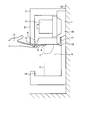
- FIG. 1 is a schematic cross-sectional view of a hand dryer according to Embodiment 1 of the present invention.
- FIG. Schematic sectional view of a hand-drying apparatus according to Embodiment 2. Schematic cross-sectional view with the cover of the hand dryer according to Embodiment 2 removed
- FIG. 1 is a schematic cross-sectional view of a hand dryer according to Embodiment 1 of the present invention.
- the hand dryer 1 according to the first embodiment includes an electric blower 3 that sends high-pressure air into a main body case 2 and a nozzle portion 4 that is installed below the electric blower 3.
- a hand drying space 5 is formed below the main body case 2 so that a user of the hand drying device 1 can insert and remove the hand 15.
- the main body case 2 has a nozzle holding surface 7 that holds the nozzle portion 4.
- the nozzle holding surface 7 is above the hand drying space 5 and is parallel to the floor surface.
- the nozzle holding surface 7 is provided with an operation unit 9 and a hand detection unit 8.
- the nozzle holding surface 7 may be directed downward when the main body case 2 is attached to the wall surface 20 and may not necessarily be parallel to the floor surface.
- the operation unit 9 is in a valid state in which the electric blower 3 is activated when the hand 15 is inserted into the detection range of the hand detection unit 8 and the electric blower 3 is activated even if the hand 15 is inserted into the detection range of the hand detection unit 8.
- An effective / invalid changeover switch for switching between invalid states and an operation mode switch for switching between operation modes is included.
- the valid / invalid changeover switch includes at least one of a power switch for switching on / off of the hand dryer 1 and a hand detection unit switch for switching on / off of the hand detection unit 8. Since the operation unit 9 is installed at a position that cannot be seen behind the main body case 2 from the perspective from the upper front side, it is difficult for general users to notice the presence of the operation unit 9. Therefore, it is prevented that a general user touches the operation part 9 easily.
- the hand detection unit 8 includes a light emitting element and a light receiving element.
- the hand detecting unit 8 detects a reflection amount and a reflection distance of the light, and changes the hand detection space. 5 is detected.
- a resin or metal filter 11 that can be attached and detached by an insertion / removal operation is installed at the lower part of the main body case 2 to remove dust in the air sucked into the electric blower 3 from the external air inlet through the intake air passage 10. Yes.
- the filter 11 is attached to and detached from the main body case 2 through a filter insertion / removal port 12 that is an opening for attaching / detaching the filter 11.
- the hand detection unit 8 reacts to actuate the electric blower 3, and the high pressure air 13 blows out from the nozzle unit 4.
- the high-pressure air 13 blown out from the nozzle unit 4 to the hand drying space 5 hits the hand 15 of the user of the hand drying device 1 and blows off water droplets adhering to the hand 15 to dry the hand 15.
- the user of the hand dryer 1 often inserts the hand 15 from the front of the main body case 2 toward the back.
- the electric blower 3 stops.
- the water droplets blown off from the user's hand 15 are collected by the water receiver 14.
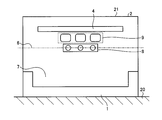
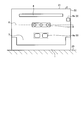
- FIG. 2 is a diagram illustrating a first arrangement example of the operation unit on the nozzle holding surface of the hand dryer according to the first embodiment. At least a part of the operation unit 9 is disposed on the nozzle holding surface 7 on the front surface 21 side of the main body case 2 with respect to the optical axis center 6 of the hand detection unit 8.
- the optical axis center 6 is the center of the light emitting element of the hand detection unit 8.
- the operation unit 9 Since at least a part of the operation unit 9 is arranged in front of the optical axis center 6 of the hand detection unit 8 on the nozzle holding surface 7, the operator operates the operation unit 9 from the front side of the hand dryer 1. In doing so, the operation unit 9 is positioned closer to the operator than the hand detection unit 8. Therefore, the operator can operate the operation unit 9 outside the detection range of the hand detection unit 8.
- the operation unit 9 can be operated without causing it to occur.
- the hand dryer 1 can operate the operation unit 9 without causing the operator to feel uncomfortable by preventing the electric blower 3 from operating unintentionally. .
- the high-pressure air 13 is not blown to the operator's hand 15 during the operation, the high-pressure air 13 is not hindered from operating the operation unit 9, and the operability can be improved.
- the front end 91 of the operation unit 9 preferably has a distance in the front-rear direction of the main body case 2 from the optical axis center 6 of the hand detection unit 8 of 60 mm or less.
- the distance in the front-rear direction from the front surface 21 of the main body case 2 to the hand detection unit 8 is set such that the front end 91 of the operation unit 9 is 60 mm or less from the optical axis center 6 of the hand detection unit 8 in the front-rear direction of the main body case 2.
- the operation unit 9 can be provided closer to the front surface 21 of the main body case 2 than the hand detection unit 8.
- the distance between the front end portion 91 of the operation unit 9 and the optical axis center 6 of the hand detection unit 8 is 60 mm or less. Since the distance from the front surface 21 to the optical axis center 6 of the hand detection unit 8 is 60 mm at the longest, a range for detecting the user's hand 15 in the hand drying space 5 can be secured.
- FIG. 3 is a diagram illustrating a second arrangement example of the operation unit on the nozzle holding surface of the hand dryer according to the first embodiment.
- the operation unit 9 may be provided on the side of the nozzle unit 4 on the nozzle holding surface 7.
- the distance in the front-rear direction of the optical axis center 6 can be shortened. That is, since the outlet of the high-pressure air 13 and the hand detection range can be brought close to each other, usability for the user can be improved.
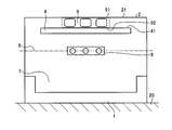
- FIG. 4 is a diagram illustrating a third arrangement example of the operation unit on the nozzle holding surface of the hand dryer according to the first embodiment.
- the front end 91 of the operation unit 9 may be adjacent to the front surface 21 of the main body case 2, and the rear end 92 of the operation unit 9 may be adjacent to the front end 41 of the nozzle unit 4. Since the front end portion 91 of the operation unit 9 is adjacent to the front surface 21 of the main body case 2 and the rear end portion 92 of the operation unit 9 is adjacent to the front end portion 41 of the nozzle unit 4, the hand drying space 5 is moved from the hand detection unit 8.
- the distance in the front-rear direction of the main body case 2 is ensured up to the rear end, the distance in the front-rear direction from the front surface 21 of the main body case 2 to the rear end of the hand drying space 5 can be minimized. That is, the depth dimension of the main body case 2 can be minimized while ensuring the hand drying space 5 into which the hand 15 is inserted.
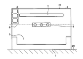
- FIG. 5 is a diagram illustrating a fourth arrangement example of the operation unit on the nozzle holding surface of the hand dryer according to the first embodiment.
- the operation unit 9 may be arranged on the nozzle holding surface 7 separately into a first operation unit 9a having a switch for switching the operation mode and a second operation unit 9b having a valid / invalid changeover switch.
- a first operation unit 9a having a switch for switching the operation mode
- a second operation unit 9b having a valid / invalid changeover switch.
- only the second operation unit 9 b is located closer to the front surface 21 side of the main body case 2 than the optical axis center 6 of the hand detection unit 8.
- the first operation unit 9 a can be provided on the back side of the main body case 2 with respect to the optical axis center 6 of the hand detection unit 8.
- the electric blower 3 is operated unintentionally by the operator by operating the first operation unit 9a after first operating the second operation unit 9b and turning off the hand drying device 1 or the hand detection unit 8.
- the first operation unit 9a can be operated while preventing this. For this reason, the number of switches arranged on the front surface 21 side of the main body case 2 relative to the hand detection unit 8 can be minimized, and the front surface 21 side of the main body case 2 from the optical axis center 6 of the hand detection unit 8 of the nozzle holding surface 7. The area can be reduced.
- FIG. 6 is a diagram illustrating a fifth arrangement example of the operation units on the nozzle holding surface of the hand dryer according to the first embodiment.
- the first operation unit 9 a may be adjacent to the side end 22 of the main body case 2.
- the operator can easily operate outside the detection range of the hand detection unit 8 when operating the second operation unit 9 b.
- the hand dryer 1 according to the first embodiment can improve operability by preventing the electric blower 3 from operating unintentionally by the operator.
- FIG. A hand dryer according to Embodiment 2 of the present invention will be described. Only parts that are different from the hand dryer according to the first embodiment will be described, and descriptions of common parts will be omitted.
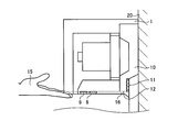
- FIG. 7 is a schematic cross-sectional view of the hand dryer according to the second embodiment.
- FIG. 8 is a schematic cross-sectional view of the hand dryer according to Embodiment 2 with the cover portion removed.
- the hand dryer 1 according to Embodiment 2 has a detachable detachable cover 16 that covers at least a part of the nozzle holding surface 7 at the lower part of the main body case 2.
- the removable cover 16 is detachable from the main body case 2. Further, the upper surface portion of the outer peripheral edge portion of the detachable cover 16 has a shape corresponding to the nozzle holding surface 7 of the main body case 2. Thereby, the detachable cover 16 is fixed to the main body case 2 by fitting the upper surface portion of the outer peripheral edge portion of the detachable cover 16 to the nozzle holding surface 7 of the main body case 2. Therefore, the detachable cover 16 and the nozzle holding surface 7 of the main body case 2 are connected and fixed by a fitting structure.
- the hand-drying apparatus 1 according to the second embodiment can be easily cleaned by removing the detachable cover 16 fixed to the lower part of the main body case 2 where dirt easily collects from the main body case 2. Therefore, even when water droplets scattered when the hand 15 is dried adhere to the detachable cover 16 and the detachable cover 16 becomes dirty, the detachable cover 16 can be kept clean by removing the detachable cover 16 and cleaning it.
- the lower surface portion of the detachable cover 16 is a flat surface and covers the operation portion 9 provided on the nozzle holding surface 7 below the main body case 2.
- the lower surface portion of the detachable cover 16 is a flat surface and covers the operation unit 9, so that the unevenness of the operation unit 9 is covered with the detachable cover 16 so that the lower part of the main body case 2 is made flat. it can. Since the lower part of the main body case 2 is a place where water droplets scattered when the hand 15 is dried adhere to the lower part of the main body case 2 and dirt is likely to accumulate when the hand 15 is continuously used, cleaning can be facilitated by forming a flat surface. Further, by covering the operation unit 9 with the detachable cover 16, the user cannot easily touch the operation unit 9.
- the filter insertion / extraction opening 12 is covered with the detachable cover 16 together with the operation unit 9.
- the number of parts can be reduced compared to a structure in which the filter insertion / removal port 12 and the operation unit 9 are covered with separate covers, and a plurality of parts are used. By doing so, it is possible to reduce a gap between components. Therefore, the hand dryer 1 according to the second embodiment can reduce the number of parts assembling steps for forming the main body case 2 and the detachable cover 16, and further suppress the occurrence of dirt accumulated in the gap between the parts. Can do.
- the configuration described in the above embodiment shows an example of the contents of the present invention, and can be combined with another known technique, and can be combined with other configurations without departing from the gist of the present invention. It is also possible to omit or change the part.
- 1 hand drying device 2 body case, 3 electric blower, 4 nozzle part, 5 hand drying space, 6 optical axis center, 7 nozzle holding surface, 8 hand detection part, 9 operation part, 9a first operation part, 9b second Operation part, 10 Intake air path, 11 Filter, 12 Filter outlet, 13 High pressure air, 14 Water receiving part, 15 Hands, 16 Detachable cover, 20 Wall surface, 21 Front face, 22 Side end, 41, 91 Front end, 92 Rear end.
Landscapes
- Health & Medical Sciences (AREA)
- Public Health (AREA)
- Structures Of Non-Positive Displacement Pumps (AREA)
- Domestic Plumbing Installations (AREA)
- Cleaning And Drying Hair (AREA)
Abstract
手乾燥装置(1)は、壁面(20)に取り付けられる本体ケース(2)と、本体ケース(2)の内部に高圧空気(13)を送出する電動送風機(3)と、電動送風機(3)の下方に設けられ高圧空気(13)を吹き出すノズル部(4)と、ノズル部(4)の下方に挿入された手(15)を検知して電動送風機(3)を作動させる手検知部(8)と、手検知部(8)の検知範囲に手(15)が挿入されると電動送風機(3)が動作する有効状態と、検知範囲に手(15)が挿入されても電動送風機(3)が動作しない無効状態とを切り替える有効無効切り替えスイッチを含む操作部(9)とを備え、本体ケース(2)は、壁面(20)に取り付けられた際に下方を向き、ノズル部(4)及び操作部(9)を保持するノズル保持面(7)を有し、有効無効切り替えスイッチは、ノズル保持面(7)の手検知部(8)の光軸中心(6)よりも本体ケース(2)の前面(21)側に設けられている。
Description
本発明は、濡れた手を乾燥させる手乾燥装置に関する。
利用者の手を検知する手検知部と、温風空気又は高速空気の気流を発生させる電動送風機とを有し、手検知部が手を検知した際に手に気流を当てて濡れた手を乾燥させる手乾燥装置が知られている。手乾燥装置は、清掃又はメンテナンスのために、手検知部の検知範囲に手が挿入されると電動送風機が作動する有効状態から、手検知部の検知範囲に手が挿入されても電動送風機が作動しない無効状態に移行可能とされる。手検知部の検知範囲に手が挿入されても電動送風機が作動しない無効状態は、手乾燥装置の電源をオフするか、手検知部を無効化することによって実現される。したがって、手乾燥装置は、電源のオンオフを切り替える電源スイッチ又は手検知部の有効無効を切り替える手検知部スイッチを有する操作部が設けられる。以下、電源スイッチ及び手検知部スイッチを有効無効切り替えスイッチという。操作部には、有効無効切り替えスイッチに加え、風量又は温度の調整といった運転モード切替えスイッチが備えられている。
特許文献1には、本体ケースは、床面と対向し且つノズル部を保持するノズル保持面を有し、ノズル保持面の一部は電動送風機に向かう方向に凹んだ凹部を有し、凹部は水平面に対して傾斜している第1平面を有し、第1平面は本体ケースの前面側から本体ケースの後面側である壁面側に向かって床面方向に傾斜しており、第1平面に操作部を設けることで、手乾燥装置の一般利用者が容易に操作部に触れることを防止しつつ、清掃又はメンテナンスのために操作部を操作する操作者にとって操作部の視認性を向上させることができる構成とした手乾燥装置が開示されている。
特許文献1に開示される手乾燥装置は、手を乾燥させる目的で手乾燥装置を使用する利用者が容易に触れることがないように、操作部が設置されている。しかし、本体ケースの正面側から本体ケース下部に手を抜き差しするという点においては、操作者の動作は、利用者の動作と同様であり、手検知部の反応により操作者にとって意図しない手乾燥装置の動作を引き起こすという課題があった。
本発明は、このような従来の課題を解決するものであり、利用者が容易に操作部に触れることを防止し、操作者にとって、意図しない手乾燥装置の動作を防止した手乾燥装置を得ることを目的とする。
上述した課題を解決し、目的を達成するために、本発明は、壁面に取り付けられる本体ケースと、本体ケースの内部に高圧空気を送出する電動送風機と、電動送風機の下方に設けられ高圧空気を吹き出すノズル部と、ノズル部の下方に挿入された手を検知して電動送風機を作動させる手検知部と、手検知部の検知範囲に手が挿入されると電動送風機が作動する有効状態と、手検知部の検知範囲に手が挿入されても電動送風機が作動しない無効状態とを切り替える有効無効切り替えスイッチを含む操作部とを備える。本体ケースは、壁面に取り付けられた際に下方を向き、ノズル部及び操作部を保持するノズル保持面を有する。有効無効切り替えスイッチは、ノズル保持面の手検知部の光軸中心よりも本体ケースの前面側に設けられている。
本発明に係る手乾燥装置は、利用者が容易に操作部に触れることを防止し、操作者にとって、意図しない手乾燥装置の動作を防止できるという効果を奏する。
以下に、本発明の実施の形態に係る手乾燥装置を図面に基づいて詳細に説明する。なお、この実施の形態によりこの発明が限定されるものではない。
実施の形態1.
図1は、本発明の実施の形態1に係る手乾燥装置の模式断面図である。実施の形態1に係る手乾燥装置1は、本体ケース2の内部に高圧空気を送出する電動送風機3と、電動送風機3の下方に設置されたノズル部4とを備えている。本体ケース2の背面側には壁掛け部分があり、この壁掛け部分によって壁面20に本体ケース2が取り付けられる。本体ケース2の下方には、手乾燥空間5が形成されており、手乾燥装置1の利用者が手15を抜き差しできるようになっている。
図1は、本発明の実施の形態1に係る手乾燥装置の模式断面図である。実施の形態1に係る手乾燥装置1は、本体ケース2の内部に高圧空気を送出する電動送風機3と、電動送風機3の下方に設置されたノズル部4とを備えている。本体ケース2の背面側には壁掛け部分があり、この壁掛け部分によって壁面20に本体ケース2が取り付けられる。本体ケース2の下方には、手乾燥空間5が形成されており、手乾燥装置1の利用者が手15を抜き差しできるようになっている。
本体ケース2は、ノズル部4を保持するノズル保持面7を有している。ノズル保持面7は、手乾燥空間5の上方にあり、床面と平行になっている。ノズル保持面7には操作部9と手検知部8とが備え付けられている。なお、ノズル保持面7は、本体ケース2が壁面20に取り付けられた際に下方を向けばよく、必ずしも床面と平行でなくてもよい。
操作部9は、手検知部8の検知範囲に手15が挿入されると電動送風機3が作動する有効状態と、手検知部8の検知範囲に手15が挿入されても電動送風機3が作動しない無効状態とを切り替える有効無効切り替えスイッチと、運転モードを切り替える運転モードスイッチとを含んでいる。有効無効切り替えスイッチは、手乾燥装置1のオンオフを切り替える電源スイッチ及び手検知部8のオンオフを切り替える手検知部スイッチの少なくとも一方を含む。操作部9は、前方斜め上からの視点では、本体ケース2の陰となって目視できない位置に設置されているため、一般利用者は操作部9の存在に気付きにくい。したがって、一般利用者が容易に操作部9に触れることは防止される。
手検知部8は、発光素子と受光素子とにより構成され、発光素子から発せられた光を受光素子が受ける際に、光の反射量及び反射距離を検出し、それらの変化により、手乾燥空間5に挿入された手15を検知する。
また、本体ケース2の下部には外部吸気口から吸気風路10を通じて電動送風機3へ吸い込まれる空気中の塵埃を除去するため、抜き差し動作で着脱できる樹脂製又は金属製のフィルタ11が設置されている。フィルタ11は、フィルタ11の着脱用の開口であるフィルタ抜き差し口12を通じて本体ケース2に着脱される。
手乾燥装置1の利用者が手15を手乾燥空間5に挿入すると、手検知部8が反応して電動送風機3が作動し、ノズル部4から高圧空気13が吹き出す。ノズル部4から手乾燥空間5に吹き出した高圧空気13は、手乾燥装置1の利用者の手15に当たり、手15に付着している水滴を吹き飛ばし手15を乾燥させる。その際、手乾燥装置1の利用者は、本体ケース2の前方から背面方向に向かって手15を挿入する場合が多い。利用者の手15が手検知部8の検知範囲から一定時間外れると電動送風機3が停止する。利用者の手15から吹き飛ばされた水滴は、水受け部14で回収される。
図2は、実施の形態1に係る手乾燥装置のノズル保持面における操作部の第1の配置例を示す図である。操作部9の少なくとも一部は、ノズル保持面7において、手検知部8の光軸中心6よりも本体ケース2の前面21側に配置されている。なお、光軸中心6とは手検知部8の発光素子の中心である。
操作部9の少なくとも一部が、ノズル保持面7において、手検知部8の光軸中心6よりも前方に配置されているため、操作者が手乾燥装置1の正面側から操作部9を操作する際に、操作部9の方が手検知部8よりも操作者の近くに位置する。したがって、操作者は、手検知部8の検知範囲外で操作部9を操作できる。
すなわち操作者は、本体ケース2の前方から背面方向に向かって手15を手乾燥空間5に挿入するという、利用者と同様の動作を行うにも関わらず、操作者は手検知部8を反応させることなく操作部9を操作できる。
操作者は下から覗き込んで操作部9を操作することになるため、操作時に電動送風機3が作動した場合、高圧空気13が操作者の顔に吹き付けられることになり、操作者に不快感を抱かせることがある。実施の形態1に係る手乾燥装置1は、操作者が意図せず電動送風機3が作動することを防止することで、操作者に不快感を抱かすことなく操作部9の操作が可能である。
また、操作時に操作者の手15に高圧空気13が吹き付けられることもなくなるため、高圧空気13によって操作部9への操作が阻害されることもなくなり、操作性を向上させることができる。
また、操作部9の前端部91は、手検知部8の光軸中心6からの本体ケース2の前後方向の距離が60mm以下であることが好ましい。操作部9の前端部91を、本体ケース2の前後方向において手検知部8の光軸中心6から60mm以下とすることで、本体ケース2の前面21から手検知部8までの前後方向の距離を短く抑えつつ、操作部9を手検知部8よりも本体ケース2の前面21側に設けることができる。すなわち、本体ケース2の前後方向において、操作部9の前端部91と手検知部8の光軸中心6との距離を60mm以下とすることにより、本体ケース2の前後方向において、本体ケース2の前面21から手検知部8の光軸中心6までの距離は最長で60mmとなるため、手乾燥空間5内に利用者の手15を検知する範囲を確保することができる。
図3は、実施の形態1に係る手乾燥装置のノズル保持面における操作部の第2の配置例を示す図である。操作部9は、ノズル保持面7のノズル部4の側方に設けてもよい。ノズル保持面7のノズル部4の側方に操作部9を設けることにより、ノズル部4と手検知部8との間に操作部9を設ける必要がないため、ノズル部4と手検知部8の光軸中心6の前後方向の距離を短くできる。すなわち、高圧空気13の吹き出し口と手検知範囲とを近づけることができるため、利用者にとっての使い勝手を向上させることができる。
図4は、実施の形態1に係る手乾燥装置のノズル保持面における操作部の第3の配置例を示す図である。操作部9の前端部91が本体ケース2の前面21に隣接し、かつ操作部9の後端部92がノズル部4の前端部41に隣接してもよい。操作部9の前端部91が本体ケース2の前面21に隣接し、かつ操作部9の後端部92がノズル部4の前端部41に隣接することにより、手検知部8から手乾燥空間5の後端まで、本体ケース2の前後方向の距離を確保した場合に、本体ケース2の前面21から手乾燥空間5後端までの前後方向の距離を最短にすることができる。すなわち手15を挿入する手乾燥空間5を確保しつつ、本体ケース2の奥行寸法を最小に構成することができる。
図5は、実施の形態1に係る手乾燥装置のノズル保持面における操作部の第4の配置例を示す図である。操作部9は、運転モードを切り替えるスイッチを備えた第1操作部9aと、有効無効切り替えスイッチを備えた第2操作部9bとに分けてノズル保持面7に配置してもよい。操作部9が第1操作部9aと第2操作部9bとに分かれた構成によれば、手検知部8の光軸中心6よりも本体ケース2の前面21側には第2操作部9bのみ設け、手検知部8の光軸中心6よりも本体ケース2の背面側に第1操作部9aを設けることができる。すなわち、操作者が第2操作部9bを操作する際は、手検知部8の検知範囲の外で操作することができる。したがって、まず第2操作部9bを操作し、手乾燥装置1又は手検知部8をオフにした後で、第1操作部9aを操作することで、操作者が意図せず電動送風機3が作動することを防止しつつ、第1操作部9aの操作をすることができる。このため、手検知部8よりも本体ケース2の前面21側に配置するスイッチの数を最小にでき、ノズル保持面7の手検知部8の光軸中心6よりも本体ケース2前面21側の面積を小さくすることができる。
図6は、実施の形態1に係る手乾燥装置のノズル保持面における操作部の第5の配置例を示す図である。操作部9を第1操作部9aと第2操作部9bとに分ける場合、第1操作部9aは、本体ケース2の側端部22に隣接させても良い。第1操作部9aを本体ケース2の側端部22に隣接させることにより、操作者が第2操作部9bを操作する際に、手検知部8の検知範囲の外で操作しやすくなる。
実施の形態1に係る手乾燥装置1は、操作者が意図せず電動送風機3が作動することを防止することで、操作性の向上を図ることができる。
実施の形態2.
本発明の実施の形態2に係る手乾燥装置について説明する。なお、実施の形態1に係る手乾燥装置と相違する部分のみ説明し、共通する部分の説明は省略する。図7は、実施の形態2に係る手乾燥装置の模式断面図である。図8は、実施の形態2に係る手乾燥装置のカバー部を外した状態での模式断面図である。実施の形態2に係る手乾燥装置1は、本体ケース2の下部に、ノズル保持面7の少なくとも一部を覆う着脱可能な着脱カバー16を有している。
本発明の実施の形態2に係る手乾燥装置について説明する。なお、実施の形態1に係る手乾燥装置と相違する部分のみ説明し、共通する部分の説明は省略する。図7は、実施の形態2に係る手乾燥装置の模式断面図である。図8は、実施の形態2に係る手乾燥装置のカバー部を外した状態での模式断面図である。実施の形態2に係る手乾燥装置1は、本体ケース2の下部に、ノズル保持面7の少なくとも一部を覆う着脱可能な着脱カバー16を有している。
着脱カバー16は、本体ケース2に対して着脱自在とされている。また、着脱カバー16の外周縁部における上面部は、本体ケース2のノズル保持面7に対応した形状を有する。これにより、着脱カバー16の外周縁部の上面部が本体ケース2のノズル保持面7に嵌ることで、着脱カバー16が本体ケース2に固定される。したがって、着脱カバー16と本体ケース2のノズル保持面7とは嵌め合い構造によって連結されて固定可能とされている。
これにより、実施の形態2にかかる手乾燥装置1は、汚れが溜まりやすい本体ケース2の下部に固定された着脱カバー16を本体ケース2から取り外して容易に清掃することができる。したがって、手15を乾燥する際に飛び散った水滴が着脱カバー16に付着し、着脱カバー16が汚れても、着脱カバー16を取り外して清掃することで、着脱カバー16を清潔に保つことができる。
また、着脱カバー16の下面部は平坦な面であり、本体ケース2下部のノズル保持面7に備えられた操作部9を覆っていることが好ましい。着脱カバー16の下面部は平坦な面であって操作部9を覆う構造とすることにより、操作部9の凹凸を着脱カバー16で覆うことで本体ケース2の下部を平坦な面にすることができる。本体ケース2の下部は、手15を乾燥する際に飛び散った水滴が付着し、使用を継続すると汚れが溜まりやすい場所であるため平坦な面にすることで清掃を容易にすることができる。また、着脱カバー16で操作部9を覆うことにより、利用者が容易に操作部9に触れることができない。
また、フィルタ抜き差し口12が操作部9とともに着脱カバー16で覆われていることが好ましい。フィルタ抜き差し口12を着脱カバー16で覆う構造とすることにより、フィルタ抜き差し口12と操作部9とを別々のカバーで覆う構造と比べて、部品点数を減らすことができ、さらに複数の部品を利用することにより生じる部品間の隙間を減らすことができる。したがって、実施の形態2に係る手乾燥装置1は、本体ケース2と着脱カバー16を形成するための部品組み立て工数を削減することができ、さらに部品と部品の隙間に溜まる汚れの発生を抑えることができる。
以上の実施の形態に示した構成は、本発明の内容の一例を示すものであり、別の公知の技術と組み合わせることも可能であるし、本発明の要旨を逸脱しない範囲で、構成の一部を省略、変更することも可能である。
1 手乾燥装置、2 本体ケース、3 電動送風機、4 ノズル部、5 手乾燥空間、6 光軸中心、7 ノズル保持面、8 手検知部、9 操作部、9a 第1操作部、9b 第2操作部、10 吸気風路、11 フィルタ、12 フィルタ抜き差し口、13 高圧空気、14 水受け部、15 手、16 着脱カバー、20 壁面、21 前面、22 側端部、41,91 前端部、92 後端部。
Claims (8)
- 壁面に取り付けられる本体ケースと、
前記本体ケースの内部に高圧空気を送出する電動送風機と、
前記電動送風機の下方に設けられ前記高圧空気を吹き出すノズル部と、
前記ノズル部の下方に挿入された手を検知して前記電動送風機を作動させる手検知部と、
前記手検知部の検知範囲に手が挿入されると前記電動送風機が動作する有効状態と、前記手検知部の検知範囲に手が挿入されても前記電動送風機が動作しない無効状態とを切り替える有効無効切り替えスイッチを含む操作部とを備え、
前記本体ケースは、前記壁面に取り付けられた際に下方を向き、前記ノズル部及び前記操作部を保持するノズル保持面を有し、
前記有効無効切り替えスイッチは、前記ノズル保持面の前記手検知部の光軸中心よりも前記本体ケースの前面側に設けられていることを特徴とする手乾燥装置。 - 前記操作部の前端部は、前記手検知部の光軸中心からの距離が、前記本体ケースの前後方向に60mm以下であることを特徴とする請求項1に記載の手乾燥装置。
- 前記操作部は、前記ノズル保持面の前記ノズル部の側方に設けられることを特徴とする請求項1又は2に記載の手乾燥装置。
- 前記操作部の前端部が前記本体ケースの前端部に隣接し、かつ前記操作部の後端部が前記ノズル部の前端部に隣接していることを特徴とする請求項1から3のいずれか1項に記載の手乾燥装置。
- 前記操作部は、第1操作部と第2操作部とに分けられており、
前記第1操作部は、前記有効無効切り替えスイッチ以外のスイッチを有し、
前記第2操作部は、前記有効無効切り替えスイッチを有し、
前記第2操作部は、前記手検知部よりも前記本体ケースの前面側の前記ノズル保持面に設けられることを特徴とする請求項1から4のいずれか1項に記載の手乾燥装置。 - 前記本体ケースの外側に、前記ノズル保持面の少なくとも一部を覆い、前記本体ケースに着脱可能な着脱カバーを有することを特徴とする請求項1から5のいずれか1項に記載の手乾燥装置。
- 前記操作部は、前記着脱カバーの内側に設けられることを特徴とする請求項6に記載の手乾燥装置。
- 前記本体ケースの下部に、外部吸気口から前記電動送風機へ吸い込まれる空気中の塵埃を除去する着脱可能なフィルタを有し、
前記フィルタを着脱する開口は、前記着脱カバーで覆われていることを特徴とする請求項6又は7に記載の手乾燥装置。
Priority Applications (2)
| Application Number | Priority Date | Filing Date | Title |
|---|---|---|---|
| PCT/JP2018/016812 WO2019207686A1 (ja) | 2018-04-25 | 2018-04-25 | 手乾燥装置 |
| JP2020515373A JP6964765B2 (ja) | 2018-04-25 | 2018-04-25 | 手乾燥装置 |
Applications Claiming Priority (1)
| Application Number | Priority Date | Filing Date | Title |
|---|---|---|---|
| PCT/JP2018/016812 WO2019207686A1 (ja) | 2018-04-25 | 2018-04-25 | 手乾燥装置 |
Publications (1)
| Publication Number | Publication Date |
|---|---|
| WO2019207686A1 true WO2019207686A1 (ja) | 2019-10-31 |
Family
ID=68293837
Family Applications (1)
| Application Number | Title | Priority Date | Filing Date |
|---|---|---|---|
| PCT/JP2018/016812 Ceased WO2019207686A1 (ja) | 2018-04-25 | 2018-04-25 | 手乾燥装置 |
Country Status (2)
| Country | Link |
|---|---|
| JP (1) | JP6964765B2 (ja) |
| WO (1) | WO2019207686A1 (ja) |
Citations (2)
| Publication number | Priority date | Publication date | Assignee | Title |
|---|---|---|---|---|
| JP2008051909A (ja) * | 2006-08-23 | 2008-03-06 | Toto Ltd | 情報提供機能付き手乾燥装置 |
| WO2013011701A1 (ja) * | 2011-07-21 | 2013-01-24 | 三菱電機株式会社 | 手乾燥装置 |
Family Cites Families (1)
| Publication number | Priority date | Publication date | Assignee | Title |
|---|---|---|---|---|
| JP2012090971A (ja) * | 2010-09-30 | 2012-05-17 | Toto Ltd | トイレ装置 |
-
2018
- 2018-04-25 WO PCT/JP2018/016812 patent/WO2019207686A1/ja not_active Ceased
- 2018-04-25 JP JP2020515373A patent/JP6964765B2/ja active Active
Patent Citations (2)
| Publication number | Priority date | Publication date | Assignee | Title |
|---|---|---|---|---|
| JP2008051909A (ja) * | 2006-08-23 | 2008-03-06 | Toto Ltd | 情報提供機能付き手乾燥装置 |
| WO2013011701A1 (ja) * | 2011-07-21 | 2013-01-24 | 三菱電機株式会社 | 手乾燥装置 |
Also Published As
| Publication number | Publication date |
|---|---|
| JPWO2019207686A1 (ja) | 2020-12-03 |
| JP6964765B2 (ja) | 2021-11-10 |
Similar Documents
| Publication | Publication Date | Title |
|---|---|---|
| JP5836380B2 (ja) | 手乾燥装置 | |
| TWI548383B (zh) | Hand drying device | |
| JP2016202509A (ja) | 電気掃除機 | |
| WO2019207686A1 (ja) | 手乾燥装置 | |
| JP4289298B2 (ja) | 手乾燥装置 | |
| JP6727434B2 (ja) | 手乾燥装置 | |
| KR102328244B1 (ko) | 청소기 | |
| TWI661800B (zh) | Hand dryer | |
| JP5720602B2 (ja) | 空気清浄機ユニット | |
| TWI671050B (zh) | 烘手裝置 | |
| JP4670211B2 (ja) | 電気掃除機 | |
| JP6080111B2 (ja) | 手乾燥装置 | |
| JP6043960B2 (ja) | 電気掃除機 | |
| JP6704529B2 (ja) | 手乾燥装置 | |
| HK1214106A1 (zh) | 手干燥装置 | |
| TW201912091A (zh) | 烘手裝置 | |
| JP4416590B2 (ja) | 空気清浄機 | |
| KR100778708B1 (ko) | 진공청소기용 모터보호장치 | |
| JP2019195365A (ja) | 手乾燥装置 | |
| JP2017018413A (ja) | 電気掃除機 | |
| JP2006167077A (ja) | 手乾燥装置 | |
| JP2006320457A (ja) | 電気掃除機 | |
| KR20170081434A (ko) | 장갑을 갖는 휴대용 청소기 |
Legal Events
| Date | Code | Title | Description |
|---|---|---|---|
| 121 | Ep: the epo has been informed by wipo that ep was designated in this application |
Ref document number: 18916707 Country of ref document: EP Kind code of ref document: A1 |
|
| ENP | Entry into the national phase |
Ref document number: 2020515373 Country of ref document: JP Kind code of ref document: A |
|
| NENP | Non-entry into the national phase |
Ref country code: DE |
|
| 122 | Ep: pct application non-entry in european phase |
Ref document number: 18916707 Country of ref document: EP Kind code of ref document: A1 |