WO2019198533A1 - 配管構造体およびその配管構造体の製造方法 - Google Patents
配管構造体およびその配管構造体の製造方法 Download PDFInfo
- Publication number
- WO2019198533A1 WO2019198533A1 PCT/JP2019/013647 JP2019013647W WO2019198533A1 WO 2019198533 A1 WO2019198533 A1 WO 2019198533A1 JP 2019013647 W JP2019013647 W JP 2019013647W WO 2019198533 A1 WO2019198533 A1 WO 2019198533A1
- Authority
- WO
- WIPO (PCT)
- Prior art keywords
- pipe
- elastic
- pressing
- elastic member
- tube
- Prior art date
- Legal status (The legal status is an assumption and is not a legal conclusion. Google has not performed a legal analysis and makes no representation as to the accuracy of the status listed.)
- Ceased
Links
Images





Classifications
-
- F—MECHANICAL ENGINEERING; LIGHTING; HEATING; WEAPONS; BLASTING
- F16—ENGINEERING ELEMENTS AND UNITS; GENERAL MEASURES FOR PRODUCING AND MAINTAINING EFFECTIVE FUNCTIONING OF MACHINES OR INSTALLATIONS; THERMAL INSULATION IN GENERAL
- F16L—PIPES; JOINTS OR FITTINGS FOR PIPES; SUPPORTS FOR PIPES, CABLES OR PROTECTIVE TUBING; MEANS FOR THERMAL INSULATION IN GENERAL
- F16L13/00—Non-disconnectable pipe joints, e.g. soldered, adhesive, or caulked joints
- F16L13/14—Non-disconnectable pipe joints, e.g. soldered, adhesive, or caulked joints made by plastically deforming the material of the pipe, e.g. by flanging, rolling
-
- F—MECHANICAL ENGINEERING; LIGHTING; HEATING; WEAPONS; BLASTING
- F16—ENGINEERING ELEMENTS AND UNITS; GENERAL MEASURES FOR PRODUCING AND MAINTAINING EFFECTIVE FUNCTIONING OF MACHINES OR INSTALLATIONS; THERMAL INSULATION IN GENERAL
- F16L—PIPES; JOINTS OR FITTINGS FOR PIPES; SUPPORTS FOR PIPES, CABLES OR PROTECTIVE TUBING; MEANS FOR THERMAL INSULATION IN GENERAL
- F16L25/00—Construction or details of pipe joints not provided for in, or of interest apart from, groups F16L13/00 - F16L23/00
- F16L25/02—Construction or details of pipe joints not provided for in, or of interest apart from, groups F16L13/00 - F16L23/00 specially adapted for electrically insulating the two pipe ends of the joint from each other
Definitions
- the present disclosure relates to a piping structure in which a first pipe member and a second pipe member are connected to each other, and a manufacturing method of the piping structure.
- an insulating joint described in Patent Document 1 has been conventionally known.
- one tubular member and the other tubular member are connected so that fluid can flow in a state where they are electrically insulated.
- the one and the other tubular members are mutually connected in a state where the enlarged end portion of one tubular member is inserted into the inside of the enlarged end portion of the other tubular member. It is connected.
- Two hard sleeves and an O-ring are inserted between the enlarged end portions in a compressed state.
- each enlarged end portion has a special shape that is partially expanded in the radial direction.
- Each of the two hard sleeves is pre-shaped into a special shape following the respective enlarged end portions.
- an O-ring is required to ensure airtightness. Therefore, it is difficult to say that the insulating joint of Patent Document 1 realizes the connection of two tubular members with a simple structure. As a result of detailed studies by the inventors, the above has been found.
- An object of the present invention is to provide a piping structure that can be connected with a simple structure, and a method for manufacturing the piping structure.
- a piping structure includes: A pipe structure in which the first pipe member and the second pipe member are connected in a state of being insulated from each other so that fluid flows from the tubular first pipe member into the tubular second pipe member, A first connecting pipe portion that forms a part of the first pipe member, includes the tip of the first pipe member, and is formed so as to extend in the axial direction of the uniaxial center; A part of the second pipe member is formed to include the tip of the second pipe member and extend in the axial direction. The tip of the second pipe member is spaced apart from the tip of the first pipe member in the axial direction.
- a second connecting pipe portion arranged in series with respect to the first connecting pipe portion so as to face each other,
- An elastic member having a tubular first elastic part into which the first connecting pipe part is inserted and a tubular second elastic part into which the second connecting pipe part is inserted, and having elasticity and insulation;
- a first elastic portion is inserted, and a tubular first pressing portion that holds the first elastic portion in a state of pressing the first elastic portion against the first connecting pipe portion;
- a second elastic part is inserted, and the second elastic part is held in a state of pressing the second elastic part against the second connecting pipe part,
- a spacer portion having an insulating property is provided,
- the second elastic part is continuously connected from the first elastic part,
- the first connecting pipe part has a first seal holding part provided on the outer peripheral surface of the first connecting pipe part, The first seal holding part exhibits airtightness with the first elastic part by pressing the first elastic part against the first seal holding part, and the first connecting pipe part is separated from the first elastic part
- the second connecting pipe part has a second seal holding part provided on the outer peripheral surface of the second connecting pipe part,
- the second seal holding part exhibits airtightness with the second elastic part by pressing the second elastic part against the second seal holding part, and the second connecting pipe part is separated from the second elastic part. Demonstrates holding power that prevents it from being pulled out.
- a method for manufacturing a piping structure includes: A method of manufacturing a piping structure in which a first pipe member and a second pipe member are connected in a state of being insulated from each other so that a fluid flows from the inside of the tubular first pipe member to the inside of the tubular second pipe member.
- a first connecting pipe part including a first seal holding part and a tip of the first pipe member among the first pipe members is inserted into the elastic member from one axial side of the elastic member, and the second pipe
- the second connecting pipe part including the second seal holding part and the tip of the second pipe member among the members is inserted into the elastic member from the other side in the axial direction, and with respect to the tip of the first pipe member in the axial direction.
- the pressing tube member is squeezed radially inward at the portion of the pressing tube member that overlaps the radially outer side with respect to the first connecting tube portion.
- the first seal holding part is provided on the outer peripheral surface of the first connecting pipe part.
- the second seal holding part is provided on the outer peripheral surface of the second connecting pipe part, and the elastic member is pressed against the second seal holding part by caulking, thereby exhibiting airtightness with the elastic member, and the second Demonstrate holding force that prevents the connecting pipe part from being pulled out of the elastic member,
- the elastic member is elastically deformed so that the thickness of the elastic member is compressed, a part of the elastic member becomes a gap between the tip of the first tube member and the tip of the second tube member. Get in.
- the piping structure according to the above-described one aspect of the present disclosure can be manufactured. That is, it is possible to connect the first tube member and the second tube member with a simple structure while ensuring airtightness and electrical insulation between the first tube member and the second tube member. Is possible.
- a part of the elastic member enters the gap between the tip of the first tube member and the tip of the second tube member, so that the gap between the tip of the first tube member and the tip of the second tube member is Electrical insulation can be ensured by the elastic member. That is, it is not necessary to previously shape the elastic member into a shape that enters between the tip of the first tube member and the tip of the second tube member. Then, by utilizing the elastic deformation of the elastic member in the caulking process, a part of the elastic member is provided between the distal end of the first tube member and the distal end of the second tube member, and sufficient electrical insulation is ensured at that portion. Is possible.
- FIG. 1 It is sectional drawing cut
- FIG. It is sectional drawing cut
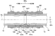
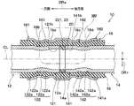
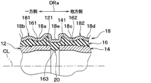
- the piping structure 10 of the present embodiment has the first pipe member 12 and the first pipe member 12 while ensuring electrical insulation between the tubular first pipe member 12 and the tubular second pipe member 14. It is comprised as an insulated joint which connects the 2 pipe member 14 airtightly. Therefore, in this piping structure 10, the first pipe member 12 and the second pipe member 14 are electrically insulated from each other so that the fluid flows from the first pipe member 12 into the second pipe member 14. It is the structure connected by.
- the fluid flowing through the first tube member 12 and the second tube member 14 is a fluid having electrical insulation.
- the fluid may be a gas or a liquid.
- the piping structure 10 is provided with the 1st pipe member 12, the 2nd pipe member 14, the elastic member 16, and the press pipe member 18, as shown in FIG.
- the first tube member 12, the second tube member 14, the elastic member 16, and the pressing tube member 18 all have a tubular shape (in other words, a tubular shape) that extends along the piping axis CL that is a uniaxial center. ing.
- the first pipe member 12 and the second pipe member 14 are made of a metal pipe material such as an aluminum alloy. Accordingly, both the first tube member 12 and the second tube member 14 have conductivity.
- the first tube member 12 is inserted into the elastic member 16 and fixed by caulking so that it cannot move relative to the elastic member 16.
- the second pipe member 14 is inserted into the elastic member 16 from the side opposite to the first pipe member 12 and is fixed by caulking so that it cannot move relative to the elastic member 16. Therefore, the first tube member 12 has a portion of the first tube member 12 located in the elastic member 16 as the first connecting tube portion 121, and the second tube member 14 is elastic among the second tube member 14. A portion located in the member 16 is provided as the second connecting pipe portion 141.
- the first connecting pipe portion 121 constitutes a part of the first pipe member 12 and includes a first pipe tip 12 a that is the tip 12 a of the first pipe member 12.
- the second connecting pipe portion 141 constitutes a part of the second pipe member 14, and includes a second pipe tip 14 a that is the tip 14 a of the second pipe member 14.
- the 1st connecting pipe part 121 and the 2nd connecting pipe part 141 are formed so that it may extend in the axial direction DRa of piping axis CL.
- each of the first connecting pipe portion 121 and the second connecting pipe portion 141 has, for example, a pipe shape with a circular cross section.
- the tube diameter of the first connection tube portion 121 may be different from the tube diameter of the second connection tube portion 141, in this embodiment, the tube diameter of the first connection tube portion 121 is the second connection tube portion 141. It is the same as the tube diameter. That is, the inner diameter of the first connecting pipe part 121 is the same as the inner diameter of the second connecting pipe part 141, and the outer diameter of the first connecting pipe part 121 is the same as the outer diameter of the second connecting pipe part 141.
- the second connecting pipe portion 141 is arranged so that the first connecting pipe is opposed to the first pipe tip 12a with a gap 20 with respect to the first pipe tip 12a in the axial direction DRa of the pipe axis CL.
- the unit 121 is arranged in series. That is, in the axial direction DRa of the piping axis CL, the first connecting pipe portion 121 is disposed on one side with respect to the pipe mutual gap 20 that is the gap 20, and the second connecting pipe portion 141 is provided with respect to the pipe mutual gap 20. Arranged on the other side.
- each of the first connecting pipe 121, the second connecting pipe 141, the elastic member 16, and the pressing pipe member 18 is the pipe axis CL, and is common. Accordingly, the axial directions of the first connecting pipe 121, the second connecting pipe 141, the elastic member 16, and the pressing pipe member 18 are all the axial direction DRa of the pipe axis CL. Similarly, the radial directions of the first connecting pipe portion 121, the second connecting pipe portion 141, the elastic member 16, and the pressing pipe member 18 are all the radial direction DRr of the pipe axis CL. Yes. Further, the circumferential directions of the first connecting pipe portion 121, the second connecting pipe portion 141, the elastic member 16, and the pressing pipe member 18 are all the same as the circumferential direction around the pipe axis CL.
- the axial direction DRa of the piping axis CL is also referred to as the piping axis direction DRa
- the radial direction DRr of the piping axis CL is also referred to as the piping radial direction DRr
- the circumferential direction around the piping axis CL is defined as the pipe circumference. Also called direction.
- the elastic member 16 is made of an insulating material having elasticity. Examples of such an insulating material include rubber or elastomer, but the elastic member 16 of this embodiment is made of rubber. Specifically, the elastic member 16 is composed of a multilayer rubber in which a rubber layer, a fiber layer, and another rubber layer are laminated in the pipe radial direction DRr in order to increase the tensile strength in the pipe axial direction DRa. ing. The fiber layer is included in the elastic member 16 so as not to be exposed on both the radially outer side and the radially inner surface of the elastic member 16. Due to such a configuration, the elastic member 16 has elasticity and electrical insulation. The internal pressure in the pipe members 12 and 14 also acts as a tensile force that pulls the elastic member 16 in the pipe axis direction DRa.
- the elastic member 16 has a tubular first elastic part 161 into which the first connecting pipe part 121 is inserted, and a tubular second elastic part 162 into which the second connecting pipe part 141 is inserted.
- the portion of the elastic member 16 that is provided on the outer side in the radial direction with respect to the first connecting pipe portion 121 corresponds to the first elastic portion 161
- the elastic member 16 includes the second connecting pipe portion 141.
- a portion provided on the outer side in the radial direction corresponds to the second elastic portion 162.
- each of the first elastic part 161 and the second elastic part 162 is a part of the elastic member 16 that is a single component, the second elastic part 162 is continuously continuous from the first elastic part 161. linked.
- the pressing tube member 18 is made of a metal pipe material such as an aluminum alloy. Therefore, the pressing tube member 18 has conductivity.
- the pressing tube member 18 has a first pressing part 181 and a second pressing part 182. Since each of the first pressing portion 181 and the second pressing portion 182 is a part of the pressing tube member 18 that is a single component, the second pressing portion 182 is continuously continuous from the first pressing portion 181. linked.
- the first elastic part 161 is inserted in the first pressing part 181. Accordingly, the first elastic portion 161 is sandwiched between the first pressing portion 181 and the first connecting pipe portion 121 in the pipe radial direction DRr.
- a second elastic portion 162 is inserted in the second pressing portion 182. Accordingly, the second elastic portion 162 is sandwiched between the second pressing portion 182 and the second connecting tube portion 141 in the pipe radial direction DRr.
- the elastic member 16 is sandwiched between the pressing tube member 18 and the first tube member 12 and between the pressing tube member 18 and the second tube member 14 over the entire length of the pressing tube member 18. Therefore, the pressing tube member 18 is electrically insulated from both the first tube member 12 and the second tube member 14. Further, the first elastic portion 161 extends so as to protrude further to the one side in the pipe axis direction DRa than the pressing tube member 18. Similarly to this, the second elastic portion 162 extends further to the other side in the pipe axis direction DRa than the pressing pipe member 18.
- the first pressing portion 181 is crimped in the pipe radial direction DRr, and holds the first elastic portion 161 against the first connecting pipe portion 121 by the crimping.
- the second pressing portion 182 is caulked in the pipe radial direction DRr, and the second elastic portion 162 is held against the second connecting pipe portion 141 by the caulking.
- the pressing tube member 18 is provided with a total of five crimping locations. That is, the pressing tube member 18 includes first to fifth crimping portions 18a, 18b, 18c, 18d, and 18e that are deformed by crimping.
- the first caulking portion 18 a has a concave shape that is recessed radially inward of the pressing tube member 18, and the concave shape is formed over the entire circumference of the pressing tube member 18.
- the second to fifth caulking portions 18b, 18c, 18d, and 18e are the same applies.
- the first caulking portion 18a and the second caulking portion 18b are formed in the first pressing portion 181, and the second caulking portion 18b is provided on one side of the pipe axial direction DRa with respect to the first caulking portion 18a. That is, the first pressing portion 181 is in a crimped state so that the respective concave shapes of the first crimping portion 18a and the second crimping portion 18b are formed, and the crimped state is obtained.
- the first elastic part 161 is pressed against the first connecting pipe part 121.
- At least one of the plurality of caulking portions 18a and 18b included in the first pressing portion 181 is located at a portion overlapping the outside in the pipe radial direction DRr with respect to the first seal holding portion 122 included in the first connecting pipe portion 121.
- the 2nd crimping part 18b is provided in the site
- the third caulking portion 18c and the fourth caulking portion 18d are formed in the second pressing portion 182, and the fourth caulking portion 18d is provided on the other side in the pipe axis direction DRa with respect to the third caulking portion 18c. That is, the second pressing portion 182 is in a crimped state so that the respective concave shapes of the third crimping portion 18c and the fourth crimping portion 18d are formed, and by being in the crimped state. The second elastic part 162 is pressed against the second connecting pipe part 141.
- At least one of the plurality of crimping portions 18c and 18d included in the second pressing portion 182 is located at a portion overlapping the outside in the pipe radial direction DRr with respect to the second seal holding portion 142 included in the second connection pipe portion 141. Is provided.
- the fourth caulking portion 18d is provided in a portion of the second pressing portion 182 that overlaps the outside in the pipe radial direction DRr with respect to the second seal holding portion 142.
- the fifth caulking portion 18e is provided at a substantially central portion of the pressing tube member 18 in the pipe axis direction DRa, and is formed so as to straddle the first pressing portion 181 and the second pressing portion 182.
- first pressing portion 181 includes a first crimping portion 18a and a second crimping portion 18b
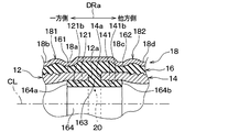
- second pressing portion 182 includes a third crimping portion 18c and a fourth crimping portion 18d. Is line symmetric with respect to the pipe axis direction DRa about the pipe gap 20.
- the elastic member 16 has a spacer portion 163 provided between the first tube tip 12a and the second tube tip 14a. Since the spacer portion 163 is a part of the elastic member 16, it has electrical insulation.
- the spacer portion 163 is a portion formed by crimping the pressing tube member 18 and elastically deforming the elastic member 16. Therefore, the elastic member 16 has a portion of the elastic member 16 that is in a state where the elastic member 16 enters the pipe gap 20 by being pressed by the crimped first and second pressing portions 181 and 182. 163.
- the spacer portion 163 plays a role against the external force when an external force is generated to bring the first tube tip 12a and the second tube tip 14a closer to the pipe axis direction DRa. Therefore, the spacer portion 163 may be partially configured between the first tube tip 12a and the second tube tip 14a, or may be configured over the entire circumference around the pipe axis CL.
- the fifth caulking portion 18e is disposed so as to overlap the outer side of the pipe radial direction DRr with respect to the spacer portion 163.
- the fifth caulking portion 18e is deformed inwardly in the pipe radial direction DRr by caulking.
- the fifth caulking portion 18e presses the elastic member 16 inward in the pipe radial direction DRr, and holds the spacer portion 163 in a state where it is pushed into the pipe mutual gap 20. That is, the fifth caulking portion 18 e functions as a pushing portion that pushes the spacer portion 163 into the pipe mutual gap 20.
- the first pipe tip 12a has an outer peripheral edge 12b outside the pipe radial direction DRr in the first pipe front end 12a, and the outer peripheral edge 12b has a chamfered shape.
- the second pipe tip 14a has an outer peripheral edge 14b outside the second pipe front end 14a in the pipe radial direction DRr, and the outer peripheral edge 14b has a chamfered shape.
- Any of these chamfered shapes makes it easy to insert the first and second pipe members 12, 14 into the elastic member 16 when the piping structure 10 is manufactured, and the spacer portion 163 is formed by elastic deformation of the elastic member 16. It is for promoting that is formed. Therefore, the chamfered shape may be a shape chamfered so as to form a corner R or a shape chamfered linearly.
- the first connecting pipe part 121 of the first pipe member 12 has a first seal holding part 122 provided on the outer peripheral surface 121a of the first connecting pipe part 121.
- the first seal holding portion 122 has an uneven shape in which a plurality of grooves 122a extending annularly over the entire circumference of the first connecting pipe portion 121 are arranged in the pipe axis direction DRa. Therefore, the first seal holding part 122 exhibits airtightness with the first elastic part 161 by pressing the first elastic part 161 against the first seal holding part 122, and the first connecting pipe part. The holding force which prevents 121 from being pulled out from the 1st elastic part 161 is exhibited.
- the first seal holding part 122 having the concavo-convex shape has an airtightness between the first connecting pipe part 121 and the first elastic part 161 as compared to a smooth surface without the concavo-convex shape. High holding power.
- the second connecting pipe part 141 of the second pipe member 14 has a second seal holding part 142 provided on the outer peripheral surface 141a of the second connecting pipe part 141.
- the second seal holding portion 142 has an uneven shape in which a plurality of grooves 142a extending in an annular shape over the entire circumference of the second connecting pipe portion 141 are arranged in the pipe axis direction DRa. Therefore, the second seal holding portion 142 exhibits airtightness with the second elastic portion 162 when the second elastic portion 162 is pressed against the second seal holding portion 142, and the second connecting pipe portion.
- the holding force which prevents 141 from being pulled out from the 2nd elastic part 162 is exhibited.
- the second seal holding portion 142 having the uneven shape has an airtightness between the second connecting pipe portion 141 and the second elastic portion 162 as compared to the case where the second seal holding portion 142 is a smooth surface without the uneven shape. High holding power.
- the force for pulling out the first connecting pipe 121 from the first elastic part 161 is generated by, for example, an external force acting on the first pipe member 12 or an internal pressure in the pipe members 12 and 14. The same applies to the force for pulling out the second connecting pipe portion 141 from the second elastic portion 162.
- each of the elastic member 16 and the pressing pipe member 18 has a straight pipe shape extending without changing its cross section in the pipe axis direction DRa. .
- the thickness of the pressing tube member 18 is significantly thinner than the thicknesses of the first tube member 12 and the second tube member 14.
- each member is illustrated with a radial gap between each member for easy understanding.
- the first connecting pipe portion 121 and the second connecting pipe portion 141 are actually in contact with the elastic member 16, respectively, but are shown with a radial gap between them.
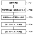
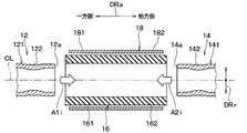
- the elastic member 16 is inserted into the inside of the pressing tube member 18 that is a sleeve. At this time, as shown in FIG. 3, the elastic member 16 is positioned in a state where it protrudes from both sides in the pipe axis direction DRa with respect to the pressing pipe member 18.
- the relative positional relationship between the elastic member 16 and the pressing tube member 18 can be set by a jig, for example, and is held by the jig.
- the elastic member 16 is connected to the first connecting pipe portion 121 of the first tube member 12 from one side in the pipe axis direction DRa as indicated by an arrow A1i in FIG. Insert inside.
- the second connecting pipe portion 141 of the second pipe member 14 is inserted into the elastic member 16 from the other side in the pipe axis direction DRa as indicated by an arrow A2i in FIG.
- the first connecting pipe portion 121 and the second connection are connected in a state where the second pipe tip 14a is opposed to the first pipe tip 12a with the pipe gap 20 therebetween.
- the tube part 141 is positioned.
- the relative positional relationship among the first tube member 12, the second tube member 14, and the elastic member 16 can be set by a jig, for example, and is held by the jig.
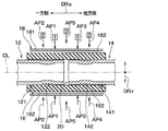
- first caulking is performed in which the pressing pipe member 18 is caulked simultaneously with respect to each of the first connecting pipe part 121 and the second connecting pipe part 141. That is, in the first caulking process, the pressing tube member 18 is moved radially inward as indicated by arrows AP1 and AP2 in FIG. 4 in a portion of the pressing tube member 18 that overlaps the first connection tube portion 121 on the radially outer side. Caulking. At the same time, the pressing tube member 18 is caulked radially inward as indicated by arrows AP3 and AP4 in FIG. 4 at a portion of the pressing tube member 18 that overlaps the second connecting tube portion 141 on the radially outer side.
- the pressing pipe member 18 is caulked with respect to each of the first connecting pipe part 121 and the second connecting pipe part 141 at a position symmetric with respect to the pipe axial direction DRa with the pipe mutual gap 20 as the center.
- the numbers shown at the base ends of the arrows AP1, AP2, AP3, AP4, and AP5 in FIG. 4 indicate the order in which caulking is performed.
- the first crimping portion 18a of FIG. 5 is formed by crimping the pressing tube member 18 as indicated by the arrow AP1.
- the pressing tube member 18 is caulked to form the third caulking portion 18c in FIG.
- the elastic member 16 is compressed immediately below the first caulking portion 18a, and the flesh of the elastic member 16 is as shown by the arrow AL1 in FIG. Flow in direction DRa.
- the elastic member 16 is compressed immediately below the third caulking portion 18c, and the meat of the elastic member 16 is piped as indicated by an arrow AL3 in FIG. It flows in the axial direction DRa.
- the caulking indicated by arrows AP2 and AP4 in FIG. 4 is performed. Specifically, as shown by the arrow AP2, the pressing tube member 18 is caulked to form the second caulking portion 18b of FIG. At the same time, as shown by the arrow AP4, the pressing tube member 18 is caulked to form the fourth caulking portion 18d. At this time, the first elastic part 161 of the elastic member 16 is compressed immediately below the second caulking part 18b as the second caulking part 18b is formed by caulking, and the first elastic part 161 holds the first seal. It is pressed against the part 122.
- the second elastic portion 162 of the elastic member 16 is compressed immediately below the fourth caulking portion 18d, and the second elastic portion 162 is second sealed. It is pressed against the holding part 142. After the first caulking process P04 in FIG. 2, the process proceeds to the second caulking process P05.
- the caulking claw for performing caulking at four locations indicated by arrows AP1, AP2, AP3, and AP4 is pressed against the pressing tube member 18 in the following state. It progresses to the 2nd crimping process P05. Thereby, it is possible to prevent the positional deviation between the first pipe member 12 and the second pipe member 14 and to set the pipe mutual gap 20 to a desired size.
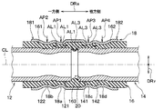
- the pressure pipe member 18 is placed inside the pipe radial direction DRr as indicated by an arrow AP5 in FIG.
- a second caulking process is performed. Specifically, as shown by the arrow AP5, the pressing tube member 18 is caulked to form the fifth caulking portion 18e of FIG.
- the elastic member 16 is further pushed into the pipe gap 20 as shown by the arrow AL5 in FIG. 6 with the formation of the fifth caulking portion 18e.
- a portion of the elastic member 16 that is pushed into the inter-tube gap 20 is a spacer portion 163.
- the amount of caulking for forming the fifth caulking portion 18e is relative to the inner peripheral surface 121b that is the inner wall surface of the first connecting tube portion 121 and the inner peripheral surface 141b that is the inner wall surface of the second connecting tube portion 141.
- the spacer portion 163 is adjusted so as not to protrude radially inward.
- the second elastic portion 162 is configured to be continuously connected to the first elastic portion 161.
- the 1st elastic part 161 is inserted in the 1st press part 181,
- the second elastic portion 162 is inserted into the second pressing portion 182, and the second pressing portion 182 presses the second elastic portion 162 against the second connecting pipe portion 141. keeping.
- a spacer portion 163 having electrical insulation is provided between the first tube tip 12a and the second tube tip 14a.
- the spacer portion 163 since the spacer portion 163 is provided, it is easy to sufficiently secure the insulation distance, the creepage distance, and the external force resistance between the first tube tip 12a and the second tube tip 14a. More specifically, the external force resistance means that when an external force is generated to bring the first tube tip 12a and the second tube tip 14a closer to the pipe axis direction DRa, the first tube tip is resisted against the external force. It is the performance which prevents contact with 12a and the 2nd pipe tip 14a.
- the elastic member 16 enters the inter-tube clearance 20 by being pressed by the crimped first and second pressing portions 181 and 182 of the elastic member 16.
- This portion has a spacer portion 163. Therefore, it is not necessary to provide the spacer portion 163 as a separate component from the elastic member 16. As shown in FIG. 3, it is not necessary to form the spacer portion 163 in advance on the elastic member 16 as a single component, so that the elastic member 16 can be formed into a simple shape.
- the fifth caulking portion 18e as the pushing portion presses the elastic member 16 to the inside in the pipe radial direction DRr, and holds the spacer portion 163 in the state where it is pushed into the pipe mutual gap 20. Yes. Accordingly, it is possible to easily adjust the size of the spacer portion 163 according to the pressing amount by which the fifth caulking portion 18 e presses the elastic member 16.
- the pressing tube member 18 is electrically insulated from both the first tube member 12 and the second tube member 14. Therefore, it is possible to prevent the insulation between the first tube member 12 and the second tube member 14 from being damaged through the pressing tube member 18.
- the pressing tube member 18 is insulated from at least one of the first tube member 12 and the second tube member 14. It only has to be.
- the 1st press part 181 is the state crimped so that each concave shape of the 1st crimping part 18a and the 2nd crimping part 18b may be formed, The crimping In this state, the first elastic part 161 is pressed against the first connecting pipe part 121. Accordingly, the electrical insulation between the first pressing portion 181 and the first connecting pipe portion 121 via the first elastic portion 161 is not impaired, and the gap between the first elastic portion 161 and the first connecting pipe portion 121 is reduced. Holding power and airtightness can be ensured. This is the same between the second elastic portion 162 and the second connecting pipe portion 141.
- the first seal holding portion 122 has an uneven shape in which a plurality of grooves 122a extending annularly over the entire circumference of the first connecting pipe portion 121 are arranged in the pipe axis direction DRa. Therefore, it is possible to form the first seal holding portion 122 so that the first seal holding portion 122 that exhibits airtightness and holding force has a certain width in the pipe axis direction DRa. The same applies to the second seal holding portion 142.
- the outer peripheral edge 12b of the first tube tip 12a has a chamfered shape
- the outer peripheral edge 14b of the second tube tip 14a also has a chamfered shape. Therefore, in the manufacturing process of the piping structure 10, it is possible to easily insert the first pipe member 12 and the second pipe member 14 into the elastic member 16.
- the elastic member 16 is pressed and a part of the elastic member 16 enters the pipe mutual gap 20 to form the spacer portion 163, the flow of the elastic member 16 entering the pipe mutual gap 20 is promoted. Is possible.
- the first caulking process is performed in the first caulking process P04 of FIG.
- the elastic member 16 is elastically deformed so that the thickness of the elastic member 16 is compressed. Get into 20.
- the portion that enters the pipe mutual gap 20 becomes a spacer portion 163.
- the elastic member 16 since a part of the elastic member 16 enters the inter-tube gap 20, electrical insulation between the first tube tip 12a and the second tube tip 14a can be ensured by the elastic member 16. That is, it is not necessary to pre-form the elastic member 16 in a shape that enters between the first tube tip 12a and the second tube tip 14a.
- a part of the elastic member 16 is provided as a spacer portion 163 between the first tube tip 12a and the second tube tip 14a by utilizing the elastic deformation of the elastic member 16 in the first caulking process, and the electric insulation of the portion is provided. Can be secured sufficiently.
- the fifth caulking portion 18e is inserted to push the elastic member 16 into the pipe gap 20. It is possible to reduce the amount of caulking to be formed.
- all of the first tube member 12, the second tube member 14, the elastic member 16, and the pressing tube member 18 prepared in the preparation step P01 of FIG. 2 have a simple straight tube shape. Therefore, in the insertion steps P02 and P03 subsequent to the preparation step P01, it is possible to easily fit the respective parts without being caught.
- the second caulking process is performed in the second caulking process P05 of FIG.
- the pressure pipe member 18 is moved in the pipe radial direction DRr as indicated by an arrow AP5 in FIG. 6 at a portion of the pressure pipe member 18 that overlaps the pipe gap 20 in the pipe radial direction DRr. Caulking inside.
- the elastic member 16 is further pushed into the pipe gap 20. Therefore, it is possible to easily adjust the size of the spacer portion 163 formed in the pipe gap 20 in accordance with the amount of pushing in the elastic member 16 in the second caulking process.
- the position of the inner peripheral end on the radially inner side of the spacer portion 163 is one of the inner peripheral surface 121b of the first connecting pipe portion 121 and the inner peripheral surface 141b of the second connecting pipe portion 141 or It is preferably adjusted so that both positions are aligned. If it does so, the passage sectional area of the passage through which the fluid in the 1st and 2nd pipe members 12 and 14 flows changes locally between the 1st pipe tip 12a and the 2nd pipe tip 14a. It is possible to suppress this. Therefore, it is possible to suppress the fluid flow in the first and second pipe members 12 and 14 from being disturbed at the position of the pipe gap 20. And generation
- the first elastic portion 161 extends further to the one side in the pipe axis direction DRa than the pressing pipe member 18.
- the second elastic portion 162 extends further to the other side in the pipe axis direction DRa than the pressing pipe member 18. Therefore, it is possible to ensure a sufficiently long creepage distance between the pressing tube member 18 and the first tube member 12 and a creeping distance between the pressing tube member 18 and the second tube member 14.
- the creeping distance can be easily determined according to the amount of protrusion of the first elastic portion 161 and the amount of protrusion of the second elastic portion 162 with respect to the pressing tube member 18.
- the spacer portion 163 is formed with respect to any of the inner peripheral surface 121 b of the first connecting pipe portion 121 and the inner peripheral surface 141 b of the second connecting pipe portion 141. Also, it does not protrude radially inward. Therefore, it is possible to provide the spacer portion 163 while preventing the fluid flow between the first tube member 12 and the second tube member 14 from being disturbed by the spacer portion 163.
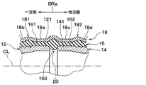
- the pressing tube member 18 is not formed with the fifth caulking portion 18e (see FIG. 1). In this respect, the present embodiment is different from the first embodiment.
- the fifth caulking portion 18e is not formed in the pressing tube member 18, since a part of the elastic member 16 enters the inter-tube clearance 20 in the first caulking process in the first caulking step P04 in FIG. As shown in FIG. 7, the spacer portion 163 is formed.
- the spacer part 163 of the present embodiment is formed smaller than the spacer part 163 of the first embodiment.
- this embodiment is the same as the first embodiment. And in this embodiment, the effect show
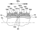
- the 1st press part 181 and the 2nd press part 182 are comprised as a separate member.
- the present embodiment is different from the first embodiment.
- the first pressing portion 181 is referred to as a first pressing member 181
- the second pressing portion 182 is referred to as a second pressing member 182.
- the fifth caulking portion 18e is not provided.
- the first pressing member 181 has a first pressing portion 181a that is disposed to overlap the spacer portion 163 in the pipe radial direction DRr.
- the 2nd press member 182 has the 2nd pushing part 182a arrange
- the first pushing portion 181a and the second pushing portion 182a correspond to the fifth caulking portion 18e of the first embodiment, and are replaced with the fifth caulking portion 18e in the present embodiment.
- the first pushing portion 181a and the second pushing portion 182a are deformed inwardly in the pipe radial direction DRr by caulking, like the fifth caulking portion 18e of the first embodiment.
- the first pushing portion 181a and the second pushing portion 182a push the elastic member 16 inward in the pipe radial direction DRr, and hold the spacer portion 163 in the state where the pipe mutual gap 20 is pushed.
- the 1st pushing part 181a and the 2nd pushing part 182a of FIG. 8 are formed in the 2nd crimping process P05 of FIG.
- this embodiment is the same as the first embodiment. And in this embodiment, the effect show
- the first and second pushing portions 181a and 182a press the elastic member 16 inward in the pipe radial direction DRr, and hold the spacer portion 163 in the state where it is pushed into the pipe mutual gap 20. ing. Therefore, similarly to the fifth caulking portion 18e of the first embodiment, the size of the spacer portion 163 is easily adjusted according to the pressing amount by which the first and second pressing portions 181a and 182a press the elastic member 16. It is possible.
- the present embodiment is the same as the first embodiment in that the elastic member 16 has a spacer portion 163.
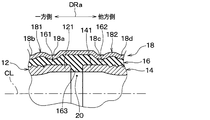
- the spacer portion 163 of the present embodiment is not formed by a part of the elastic member 16 entering the inter-tube gap 20 as the elastic member 16 is elastically deformed.
- the elastic member 16 of the present embodiment is molded in advance so as to have the spacer portion 163. That is, the elastic member 16 of this embodiment has the spacer part 163 as a part of the molded shape of the elastic member 16. In this respect, the present embodiment is different from the first embodiment.
- the spacer portion 163 is already formed on the elastic member 16 prepared in the preparation process P01 of FIG. 2, the second crimping process P05 of FIG. 2 is not performed. Therefore, as shown in FIG. 9, the fifth caulking portion 18 e (see FIG. 1) is not formed on the pressing tube member 18.
- this embodiment is the same as the first embodiment. And in this embodiment, the effect show
- the elastic member 16 has the spacer portion 163 as a part of the molded shape formed by the elastic member 16. Therefore, it is easy to make the elastic member 16 and the spacer part 163 common and to make the spacer part 163 have a desired shape with little variation.
- the 1st press part 181 and the 2nd press part 182 are comprised as a separate member.
- the present embodiment is different from the fourth embodiment. Except for this point, the present embodiment is the same as the fourth embodiment. And in this embodiment, the effect show
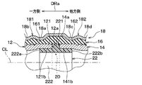
- the elastic member 16 has an in-pipe arrangement part 164 provided inside the first connection pipe part 121 and the second connection pipe part 141.
- the present embodiment is different from the fourth embodiment.
- the in-pipe arrangement portion 164 is continuously connected to the spacer portion 163.
- This in-pipe arrangement part 164 is arranged inside the pipe radial direction DRr with respect to the spacer part 163.
- the in-pipe arrangement portion 164 has a ring shape (in other words, a cylindrical shape).
- the in-pipe arrangement portion 164 extends to one side in the pipe axis direction DRa along the inner peripheral surface 121b of the first connection pipe portion 121 with respect to the spacer portion 163.
- the in-pipe arrangement portion 164 extends to the other side of the pipe axis direction DRa along the inner peripheral surface 141b of the second connection pipe portion 141 with respect to the spacer portion 163.
- the one end 164a of the pipe arrangement portion 164 on one side in the pipe axis direction DRa is located on one side of the first pipe tip 12a in the pipe axis direction DRa.
- positioning part 164 has on the other side of the pipe axis direction DRa is located in the other side rather than the 2nd pipe front-end
- the present embodiment is the same as the fourth embodiment. And in this embodiment, the effect show
- the in-pipe arrangement part 164 continuously connected from the spacer part 163 is provided inside the first connection pipe part 121 and the second connection pipe part 141.
- the in-pipe arrangement portion 164 has an annular shape, extends in the pipe axis direction DRa along the inner peripheral surface 121b of the first connection pipe portion 121, and extends along the inner peripheral surface 141b of the second connection pipe portion 141. It extends in the pipe axis direction DRa. Therefore, the creeping distance between the first connection pipe part 121 and the second connection pipe part 141 inside the first connection pipe part 121 and the second connection pipe part 141 can be increased by the in-pipe arrangement part 164. is there. Thereby, it is possible to improve the electrical insulation between the 1st connecting pipe part 121 and the 2nd connecting pipe part 141 inside the 1st connecting pipe part 121 and the 2nd connecting pipe part 141.
- this embodiment is a modification based on 4th Embodiment, it is also possible to combine this embodiment with the above-mentioned 5th Embodiment.
- the shape of the in-pipe arrangement portion 164 is different from that of the sixth embodiment.
- the inner diameter of the in-pipe arrangement portion 164 approaches the one end 164a and the other end 164b of the in-pipe arrangement portion 164 from the connecting portion where the in-pipe arrangement portion 164 is connected to the spacer portion 163. It is getting bigger.
- the thickness of the in-pipe arrangement portion 164 is the largest at the connecting portion of the in-pipe arrangement portion 164 and is the smallest at one end 164a and the other end 164b of the in-pipe arrangement portion 164.
- positioning part 164 is so small that it approaches each of the one end 164a and the other end 164b of the in-pipe arrangement
- the in-pipe arrangement portion 164 has a sharp shape at one end 164a and the other end 164b.
- the present embodiment is the same as the sixth embodiment. And in this embodiment, the effect show
- the inner diameter of the in-pipe arrangement portion 164 approaches each of the one end 164a and the other end 164b of the in-pipe arrangement portion 164 from the connecting portion where the in-pipe arrangement portion 164 is connected to the spacer portion 163. It is getting bigger. Accordingly, the in-pipe arrangement portion 164 can be shaped so as not to obstruct the flow of fluid flowing between the first pipe member 12 and the second pipe member 14. As a result, for example, abnormal noise and pressure loss caused by the in-pipe arrangement portion 164 can be suppressed.
- the spacer portion 221 of the present embodiment corresponds to the spacer portion 163 (see FIG. 9) of the fourth embodiment. Accordingly, the spacer portion 221 of the present embodiment has the same shape or substantially the same shape as the spacer portion 163 of the fourth embodiment, and the arrangement of the spacer portion 221 is the same as the spacer portion 163 of the fourth embodiment. That is, the spacer portion 221 of the present embodiment is also provided between the first tube tip 12a and the second tube tip 14a, similarly to the spacer portion 163 of the fourth embodiment.
- the spacer portion 221 of the present embodiment is not a part of the elastic member 16 but is configured as a part different from the elastic member 16. In this respect, the present embodiment is different from the fourth embodiment.
- the piping structure 10 of the present embodiment includes an annular ring member 22 in addition to the elastic member 16 and the like, and the ring member 22 serves as a spacer portion 221.
- the ring member 22 includes only the spacer portion 221.
- the ring member 22 as the spacer portion 221 is made of a resin that is an insulating material. Therefore, also in this embodiment, the spacer part 221 has electrical insulation.
- the present embodiment is the same as the fourth embodiment. And in this embodiment, the effect show
- the spacer portion 221 is configured as a component separate from the elastic member 16. Therefore, for example, by appropriately selecting the constituent material of the ring member 22, it is possible to make the spacer portion 221 have mechanical characteristics or electrical characteristics different from those of the elastic member 16.
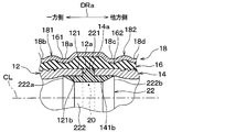
- the ring member 22 has an in-pipe arrangement portion 222 in addition to the spacer portion 221.
- the present embodiment is different from the eighth embodiment.
- the in-pipe arrangement part 222 of the present embodiment corresponds to the in-pipe arrangement part 164 (see FIG. 11) of the sixth embodiment. Therefore, the in-pipe arrangement part 222 of the present embodiment has the same shape or substantially the same shape as the in-pipe arrangement part 164 of the sixth embodiment, and the arrangement of the in-pipe arrangement part 222 is the same as the in-pipe arrangement part 164 of the sixth embodiment. is there.
- the in-pipe arrangement part 222 of the present embodiment is provided inside the first connection pipe part 121 and the second connection pipe part 141 and is continuously connected from the spacer part 221.
- positioning part 222 has in one side of the pipe axial direction DRa is located in one side rather than the 1st pipe front-end
- positioning part 222 has on the other side of the pipe axial direction DRa is located in the other side rather than the 2nd pipe front-end
- the present embodiment is the same as the eighth embodiment. And in this embodiment, the effect show
- positioning part 222 which the ring member 22 of this embodiment has corresponds to the in-pipe arrangement part 164 of 6th Embodiment. Therefore, the in-pipe arrangement part 222 of this embodiment functions in the same manner as the in-pipe arrangement part 164 of the sixth embodiment, and can obtain the same effect as the effect produced by the in-pipe arrangement part 164 of the sixth embodiment. .
- the shape of the in-pipe arrangement portion 222 is different from that of the ninth embodiment.
- the in-pipe arrangement part 222 of the present embodiment corresponds to the in-pipe arrangement part 164 (see FIG. 12) of the seventh embodiment. Therefore, the in-pipe arrangement part 222 of the present embodiment has the same shape or substantially the same shape as the in-pipe arrangement part 164 of the seventh embodiment, and the arrangement of the in-pipe arrangement part 222 is the same as the in-pipe arrangement part 164 of the seventh embodiment. is there.
- the thickness of the in-pipe arrangement part 222 is the largest at the connecting portion where the in-pipe arrangement part 222 is connected to the spacer part 221, and is the smallest at the one end 222 a and the other end 222 b of the in-pipe arrangement part 222.
- positioning part 222 is so small that it approaches each of the one end 222a and the other end 222b of the in-pipe arrangement
- the in-pipe arrangement portion 222 has a sharp shape at one end 222a and the other end 222b.
- the present embodiment is the same as the ninth embodiment. And in this embodiment, the effect show
- the in-pipe arrangement part 222 included in the ring member 22 of the present embodiment corresponds to the in-pipe arrangement part 164 of the seventh embodiment. Therefore, the in-pipe arrangement part 222 of the present embodiment functions in the same manner as the in-pipe arrangement part 164 of the seventh embodiment, and can obtain the same effects as the effects exhibited by the in-pipe arrangement part 164 of the seventh embodiment. .
- the shape of the end portion of the pressing tube member 18 of the present embodiment is different from that of the first embodiment.
- the piping structure 10 of this embodiment is formed symmetrically in the piping axis direction DRa with the pipe gap 20 (see FIG. 1) as the center, as in the first embodiment. Therefore, in FIG. 16, a portion corresponding to the XVI portion in FIG. 1 that is one portion in the pipe axis direction DRa of the pipe structure 10 is extracted and illustrated, and the other side portion in the pipe axis direction DRa is illustrated. Is omitted. This also applies to the later-described drawings that extract and show a portion corresponding to the XVI portion of FIG.
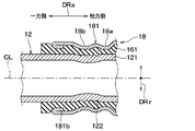
- the first pressing portion 181 is configured such that the folded portion 181b that is folded inward in the radial direction of the first pressing portion 181 has an end on one side in the pipe axis direction DRa, that is, the side opposite to the second pressing portion 182 side. At the end.
- the folded portion 181b is in close contact with the first elastic portion 161 while pressing the first elastic portion 161. Further, the folded portion 181b is disposed on one side of the pipe axis direction DRa with respect to the first seal holding portion 122.
- the second pressing part 182 (see FIG. 1) is connected to the folded part 181b of the first pressing part 181.
- the same folded portion has a symmetrical arrangement with the first pressing portion 181. That is, the folded portion of the second pressing portion 182 is provided at the other end of the second pressing portion 182 in the pipe axis direction DRa, that is, the end opposite to the first pressing portion 181 side. .
- the folded portion of the second pressing portion 182 is in close contact with the second elastic portion 162 while pressing the second elastic portion 162 (see FIG. 1). Further, the folded portion of the second pressing portion 182 is disposed on the other side in the pipe axis direction DRa with respect to the second seal holding portion 142 (see FIG. 1).
- this embodiment is the same as the first embodiment. And in this embodiment, the effect show
- the 1st press part 181 is the 2nd press part 182 side in the pipe-axis direction DRa with the folding
- the folded portion 181b is in close contact with the first elastic portion 161 while pressing the first elastic portion 161. Accordingly, the portion where the folded portion 181b is provided can be reinforced, and the first elastic portion 161 can be locked by the folded portion 181b to hold the first elastic portion 161 so that it is not easily removed from the first pressing portion 181. Is possible.
- this embodiment is a modification based on the first embodiment, it is possible to combine this embodiment with any of the second to tenth embodiments described above.
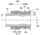
- the first connection pipe part 121 of the present embodiment has a protrusion 123 provided on the outer peripheral surface 121 a of the first connection pipe part 121.
- the present embodiment is different from the eleventh embodiment.
- the protrusion 123 protrudes from the outer peripheral surface 121a of the first connecting pipe portion 121 in the pipe radial direction DRr. Further, the protrusion 123 is disposed between the first seal holding part 122 and the folded part 181b of the first pressing part 181 in the pipe axis direction DRa.
- the protrusion 123 is formed in an annular shape over the entire circumference in the pipe circumferential direction.
- the second connection pipe portion 141 (see FIG. 1) is provided symmetrically with respect to the first connection pipe portion 121 in the pipe axis direction DRa with the pipe mutual gap 20 as the center. Therefore, the second connection pipe part 141 has a projection similar to the projection 123 of the first connection pipe part 121 in a symmetrical arrangement with respect to the first connection pipe part 121. That is, the protrusion of the second connecting pipe portion 141 is disposed between the second seal holding portion 142 and the folded portion of the second pressing portion 182 in the pipe axis direction DRa.
- this embodiment is the same as the eleventh embodiment. And in this embodiment, the effect show
- the first connecting pipe portion 121 has the annular protrusion 123 provided on the outer peripheral surface 121 a of the first connecting pipe portion 121. Therefore, it is possible to reinforce the portion where the projection 123 is provided and to hold the first connecting portion 121 so that it is difficult to come off the first elastic portion 161 by locking the first elastic portion 161 with the projection 123. Is possible.
- the first connection pipe part 121 of the present embodiment has a protrusion 123 provided on the outer peripheral surface 121 a of the first connection pipe part 121.
- the first pressing portion 181 has one end portion 181c on one side in the pipe axis direction DRa, and the one end portion 181c is formed to bend inward in the radial direction of the first pressing portion 181.
- one end 181c of the first pressing portion 181 is disposed on one side in the pipe axis direction DRa with respect to the first seal holding portion 122.
- the protrusion 123 of the 1st connection pipe part 121 of this embodiment is the same as the protrusion 123 of 12th Embodiment except the protrusion height to the pipe radial direction DRr.
- the protrusion height of the protrusion 123 of this embodiment is larger than that of the protrusion 123 of the twelfth embodiment.
- the projection 123 of this embodiment is disposed between the first seal holding part 122 and the one end part 181c of the first pressing part 181 in the pipe axis direction DRa. And the protrusion 123 is provided so that it may overlap with the other side of the pipe-axis direction DRa with respect to the one end part 181c of the 1st press part 181. As shown in FIG.
- the second connection pipe part 141 has a protrusion similar to the protrusion 123 of the first connection pipe part 121 in a symmetrical arrangement with respect to the first connection pipe part 121.
- the 2nd press part 182 has the edge part (namely, other end part) similar to the one end part 181c of the 1st press part 181 with the symmetrical arrangement with the 1st press part 181.
- this embodiment is the same as the first embodiment. And in this embodiment, the effect show
- the protrusion 123 of the first connecting pipe portion 121 is provided so as to partially overlap with the one end portion 181c of the first pressing portion 181 on the other side in the pipe axis direction DRa.
- a part of the first elastic portion 161 is interposed between the protrusion 123 and the one end portion 181c. Therefore, the first connecting pipe part 121 and the first elastic part 161 can be held by the one end part 181c of the first pressing part 181 so that the first pressing part 181 does not easily come off.
- the first connecting pipe portion 121 has the annular protrusion 123 provided on the outer peripheral surface 121 a of the first connecting pipe portion 121. Therefore, the same effect as that produced by the protrusion 123 of the twelfth embodiment can be obtained.
- this embodiment is a modification based on the first embodiment, it is possible to combine this embodiment with any of the second to tenth embodiments described above.
- first tube member 12, the second tube member 14, and the pressing tube member 18 are all made of metal and thus have conductivity. 14 and 18 may be made of an insulating material. This is the same in the second and subsequent embodiments.
- the concave shape of the first caulking portion 18a shown in FIG. 1 is formed over the entire circumference of the pressing tube member 18, but this is an example.
- the shape of the first crimping portion 18 a is not limited.
- the concave shape of the first caulking portion 18 a may be divided into a plurality of portions so as to be aligned in the circumferential direction of the pressing tube member 18. The same applies to the second to fifth caulking portions 18b, 18c, 18d, and 18e.
- the first seal holding portion 122 has an uneven shape in which a plurality of annularly extending grooves 122 a are arranged in the pipe axis direction DRa. It is an example.
- the shape of the first seal holding part 122 is not limited as long as the airtightness and holding force between the first connecting pipe part 121 and the first elastic part 161 can be sufficiently secured.
- the first seal holding portion 122 is formed with only one groove or one protrusion extending in an annular shape. The same applies to the second seal holding portion 142.
- the tube member insertion step P03 is carried out after the elastic member insertion step P02, and the elastic member insertion step P02 and the tube member insertion step P03 are Any of the implementation orders may be first. Further, the elastic member insertion step P02 and the tube member insertion step P03 may be performed simultaneously. This is the same in the second and subsequent embodiments.
- the process proceeds to the second caulking process P05 after the first caulking process P04.
- the process proceeds to the next second caulking process P05.
- the first caulking process P04 is performed in a state where any one of the four crimping claws is pressed against the first pressing portion 181 and the other one is pressed against the second pressing portion 182. May proceed to the second caulking process P05.
- the first caulking process P04 proceeds to the second caulking process P05 in a state where all the crimping claws are separated from the pressing tube member 18.
- each of the first connecting pipe portion 121 and the second connecting pipe portion 141 has, for example, a circular cross section, but this is only an example. There is no limitation in the cross-sectional shape of the 2nd connecting pipe part 121,141.
- the first pressing member 181 has a first pressing portion 181a
- the second pressing member 182 has a second pressing portion 182a. This is an example. As long as the size of the spacer portion 163 can be appropriately adjusted, one of the first pushing portion 181a and the second pushing portion 182a may not be provided.
- each crimped portion 18a, 18b, 18c, 18d, 18e of the pressing tube member 18 is as shown in FIG. 1, but various shapes of the crimped portion are conceivable. This is the same in the second and subsequent embodiments.
- the fifth caulking portion 18e of the pressing tube member 18 may have a shape that is caulked deeper in the pipe radial direction DRr than the shape shown in FIG. 1, as shown in FIG.
- the fifth caulking portion 18e may have a narrower shape than the shape shown in FIG.
- the caulking amount for forming the fifth caulking portion 18 e is the same as that of the inner peripheral surface 121 b of the first connecting tube portion 121 and the second connecting tube portion 141.
- the spacer portion 163 is adjusted so as not to protrude radially inward with respect to the inner peripheral surface 141b. However, this is an example.
- the spacer part 163 is a grade which does not disturb the flow of the fluid which flows between the 1st pipe member 12 and the 2nd pipe member 14, the internal peripheral surface 121b of the 1st connection pipe part 121 and the 2nd connection pipe Even if it protrudes to the inner side in the radial direction with respect to the inner peripheral surface 141b of the portion 141, there is no problem. That is, the amount of protrusion of the spacer portion 163 radially inward with respect to any of the inner peripheral surfaces 121b and 141b is such a size that does not disturb the fluid flow in the first and second pipe members 12 and 14.
- the caulking amount for forming the fifth caulking portion 18e only needs to be adjusted. This also applies to the embodiments in which the spacer portion 163 is provided in the same manner as the first embodiment among the embodiments after the second embodiment.
- the caulking indicated by the arrows AP1 and AP3 in FIG. 4 is followed by the caulking indicated by the arrows AP2 and AP4 in FIG. May be reversed. That is, the caulking indicated by arrows AP1 and AP3 in FIG. 4 may be performed after the caulking indicated by arrows AP2 and AP4 in FIG. This is the same in the second and subsequent embodiments.
- the elastic member having elasticity and insulation includes a tubular first elastic portion into which the first connecting pipe portion is inserted and a first elastic portion. And a tubular second elastic portion into which the two connecting pipe portions are inserted. And the 2nd elastic part is connected continuously from the 1st elastic part.
- a first elastic portion is inserted into the tubular first pressing portion, and the first pressing portion holds the first elastic portion while pressing the first elastic portion against the first connecting pipe portion.
- the 2nd elastic part is inserted in the tubular 2nd press part, The 2nd press part hold
- an insulating spacer is provided between the tip of the first tube member and the tip of the second tube member.
- the elastic member is pressed by the first pressing portion and the second pressing portion among the elastic members, whereby the tip of the first tube member and the tip of the second tube member are The part which has entered into the gap between the two has a spacer part. Therefore, it is not necessary to provide the spacer portion as a component separate from the elastic member. And since it is not necessary to shape
- one or both of the first pressing portion and the second pressing portion is a pressing portion that is arranged on the outer side with respect to the spacer portion in the radial direction of the first connecting pipe portion.
- the pushing portion presses the elastic member inward in the radial direction and holds the spacer portion in a state of being pushed into the gap. Therefore, it is possible to easily adjust the size of the spacer portion according to the pressing amount with which the pressing portion presses the elastic member.
- the 1st press part and the 2nd press part are connected continuously, and the press pipe member is comprised,
- the press pipe member is the radial direction of a 1st connection pipe part. It has a pushing part arranged on the outside with respect to the spacer part.
- the pushing portion presses the elastic member inward in the radial direction and holds the spacer portion in a state of being pushed into the gap. Therefore, it is possible to easily adjust the size of the spacer portion according to the pressing amount with which the pressing portion presses the elastic member.
- the elastic member has a spacer portion as a part of the molded shape of the elastic member. Therefore, it is easy to share the parts of the elastic member and the spacer portion, and to make the spacer portion have a desired shape with little variation.
- the spacer portion is configured as a component separate from the elastic member. Therefore, for example, by appropriately selecting the constituent material of the spacer portion, it is possible to provide the spacer portion with mechanical characteristics or electrical characteristics different from those of the elastic member.
- an in-pipe arrangement portion continuously provided from the spacer portion is provided inside the first connection pipe portion and the second connection pipe portion.
- the in-pipe arrangement portion has a cylindrical shape, extends in the axial direction along the inner wall surface of the first connection pipe portion, and extends in the axial direction along the inner wall surface of the second connection pipe portion. Therefore, the creeping distance between the first connection pipe part and the second connection pipe part inside the first connection pipe part and the second connection pipe part can be increased by the in-pipe arrangement part. Thereby, it is possible to improve the insulation between the 1st connecting pipe part and the 2nd connecting pipe part inside the 1st connecting pipe part and the 2nd connecting pipe part.
- the first tube member and the first pressing portion are both made of metal, and the first pressing portion is electrically insulated from the first tube member. Therefore, it is possible to prevent the insulation between the first pipe member and the second pipe member from being damaged through the first pressing portion.
- the 1st press part is the state crimped so that the concave shape hollowed to radial inside may be formed, and it will become 1st elasticity by becoming a crimped state.
- the part is pressed against the first connecting pipe part. Therefore, the holding force and the airtightness between the first elastic part and the first connection pipe part are reduced without impairing the insulation between the first pressing part and the first connection pipe part via the first elastic part. Can be secured.
- the concave shape is formed over the entire circumference of the first pressing portion, or is divided into a plurality of portions so as to be arranged in the circumferential direction of the first pressing portion.
- the 1st press part has the folding
- the folded portion is in close contact with the first elastic portion. Therefore, it is possible to reinforce the portion where the folded portion of the first pressing portion is provided, and to hold the first elastic portion so that it is difficult to come off from the first pressing portion.
- the first seal holding portion has an uneven shape in which a plurality of grooves extending along the entire circumference of the first connecting pipe portion are arranged in the axial direction. Therefore, it is possible to form the first seal holding portion so that the first seal holding portion that exhibits airtightness and holding force has a certain width in the axial direction.
- the distal end of the first tube member and the distal end of the second tube member each have a shape in which a radially outer peripheral edge is chamfered. Therefore, in the manufacturing process of the piping structure, it is possible to easily insert the first pipe member and the second pipe member into the elastic member. Further, when the elastic member is pressed and a part of the elastic member enters the gap between the tip of the first tube member and the tip of the second tube member to form the spacer portion, It is possible to promote the flow of the elastic member that enters.
- the elastic member in the caulking process, as the elastic member is elastically deformed so that the thickness of the elastic member is compressed, a part of the elastic member becomes the tip of the first tube member and the second tube. It enters into the gap between the tip of the pipe member.
- the pressing pipe member is disposed in the radial direction at the portion of the pressing pipe member that overlaps the gap in the radial direction of the first connecting pipe portion.
- a second caulking process that caulks inward is performed.
- the elastic member is further pushed into the gap. Therefore, the size of the spacer portion formed in the gap can be easily adjusted according to the push-in amount for pushing the elastic member in the second caulking process.
Landscapes
- Engineering & Computer Science (AREA)
- General Engineering & Computer Science (AREA)
- Mechanical Engineering (AREA)
- Non-Disconnectible Joints And Screw-Threaded Joints (AREA)
- Flanged Joints, Insulating Joints, And Other Joints (AREA)
Applications Claiming Priority (2)
| Application Number | Priority Date | Filing Date | Title |
|---|---|---|---|
| JP2018076830A JP7087612B2 (ja) | 2018-04-12 | 2018-04-12 | 配管構造体およびその配管構造体の製造方法 |
| JP2018-076830 | 2018-04-12 |
Publications (1)
| Publication Number | Publication Date |
|---|---|
| WO2019198533A1 true WO2019198533A1 (ja) | 2019-10-17 |
Family
ID=68163663
Family Applications (1)
| Application Number | Title | Priority Date | Filing Date |
|---|---|---|---|
| PCT/JP2019/013647 Ceased WO2019198533A1 (ja) | 2018-04-12 | 2019-03-28 | 配管構造体およびその配管構造体の製造方法 |
Country Status (2)
| Country | Link |
|---|---|
| JP (1) | JP7087612B2 (enExample) |
| WO (1) | WO2019198533A1 (enExample) |
Cited By (1)
| Publication number | Priority date | Publication date | Assignee | Title |
|---|---|---|---|---|
| US20230025292A1 (en) * | 2021-07-20 | 2023-01-26 | General Electric Company | Tube assembly |
Citations (3)
| Publication number | Priority date | Publication date | Assignee | Title |
|---|---|---|---|---|
| JPS511525Y1 (enExample) * | 1974-04-08 | 1976-01-17 | ||
| JPH10115388A (ja) * | 1996-10-11 | 1998-05-06 | Takenaka Komuten Co Ltd | 樹脂管継手 |
| JPH11325360A (ja) * | 1998-05-08 | 1999-11-26 | Koyo Seiko Co Ltd | 管継手 |
-
2018
- 2018-04-12 JP JP2018076830A patent/JP7087612B2/ja active Active
-
2019
- 2019-03-28 WO PCT/JP2019/013647 patent/WO2019198533A1/ja not_active Ceased
Patent Citations (3)
| Publication number | Priority date | Publication date | Assignee | Title |
|---|---|---|---|---|
| JPS511525Y1 (enExample) * | 1974-04-08 | 1976-01-17 | ||
| JPH10115388A (ja) * | 1996-10-11 | 1998-05-06 | Takenaka Komuten Co Ltd | 樹脂管継手 |
| JPH11325360A (ja) * | 1998-05-08 | 1999-11-26 | Koyo Seiko Co Ltd | 管継手 |
Cited By (2)
| Publication number | Priority date | Publication date | Assignee | Title |
|---|---|---|---|---|
| US20230025292A1 (en) * | 2021-07-20 | 2023-01-26 | General Electric Company | Tube assembly |
| US12129945B2 (en) * | 2021-07-20 | 2024-10-29 | General Electric Company | Tube assembly |
Also Published As
| Publication number | Publication date |
|---|---|
| JP2019183992A (ja) | 2019-10-24 |
| JP7087612B2 (ja) | 2022-06-21 |
Similar Documents
| Publication | Publication Date | Title |
|---|---|---|
| US7810848B2 (en) | Pipe joint and pipe joint structure having the same and method of using the same | |
| JP5520293B2 (ja) | 連結具及び連結具で使用されるグリップ式固定リングの製造方法 | |
| WO2011034959A2 (en) | Variable canted coil spring cross section | |
| CN102593971A (zh) | 用于旋转电机的定子以及制造所述定子的方法 | |
| US20060220380A1 (en) | Piping joint device and manufacturing method thereof | |
| EP3043099B1 (en) | Sealing member for pipe connection comprising protrusions | |
| EP1681477B1 (en) | Combination of a snap ring with a shaft and a holding member | |
| CN107314111A (zh) | 密封环及密封结构 | |
| JP2019183992A (ja) | 配管構造体およびその配管構造体の製造方法 | |
| US7614475B2 (en) | Longitudinal stringer exhaust flex pipe assembly | |
| US20230392723A1 (en) | Multi-hose arrangement | |
| JP2005282701A (ja) | 防振ゴムブッシュとその製造方法 | |
| US9746111B2 (en) | Hydraulic tube for vehicle | |
| JP2019015357A (ja) | 断熱部材の製作方法 | |
| JP2015215030A (ja) | 配管の接続構造 | |
| KR200449005Y1 (ko) | 방폭용 플렉시블 조인트 | |
| JP2017168296A (ja) | 端子アッシーおよびその製造方法 | |
| JP2019183992A5 (enExample) | ||
| CN115384607A (zh) | 电动转向装置 | |
| WO2019065762A1 (ja) | 管継手 | |
| JP5125321B2 (ja) | 連結クランプ | |
| CN213745349U (zh) | 一种插接管道的密封结构 | |
| CN111247365A (zh) | 一种管路快接装置 | |
| CN218119006U (zh) | 管路连接结构、发动机管路及车辆 | |
| JP2022186322A (ja) | 二重管の成形方法 |
Legal Events
| Date | Code | Title | Description |
|---|---|---|---|
| 121 | Ep: the epo has been informed by wipo that ep was designated in this application |
Ref document number: 19784923 Country of ref document: EP Kind code of ref document: A1 |
|
| NENP | Non-entry into the national phase |
Ref country code: DE |
|
| 122 | Ep: pct application non-entry in european phase |
Ref document number: 19784923 Country of ref document: EP Kind code of ref document: A1 |