WO2019198228A1 - 空気調和機 - Google Patents
空気調和機 Download PDFInfo
- Publication number
- WO2019198228A1 WO2019198228A1 PCT/JP2018/015533 JP2018015533W WO2019198228A1 WO 2019198228 A1 WO2019198228 A1 WO 2019198228A1 JP 2018015533 W JP2018015533 W JP 2018015533W WO 2019198228 A1 WO2019198228 A1 WO 2019198228A1
- Authority
- WO
- WIPO (PCT)
- Prior art keywords
- compressor
- pressure
- air conditioner
- opening valve
- cylindrical portion
- Prior art date
- Legal status (The legal status is an assumption and is not a legal conclusion. Google has not performed a legal analysis and makes no representation as to the accuracy of the status listed.)
- Ceased
Links
Images






Classifications
-
- F—MECHANICAL ENGINEERING; LIGHTING; HEATING; WEAPONS; BLASTING
- F25—REFRIGERATION OR COOLING; COMBINED HEATING AND REFRIGERATION SYSTEMS; HEAT PUMP SYSTEMS; MANUFACTURE OR STORAGE OF ICE; LIQUEFACTION SOLIDIFICATION OF GASES
- F25B—REFRIGERATION MACHINES, PLANTS OR SYSTEMS; COMBINED HEATING AND REFRIGERATION SYSTEMS; HEAT PUMP SYSTEMS
- F25B1/00—Compression machines, plants or systems with non-reversible cycle
-
- F—MECHANICAL ENGINEERING; LIGHTING; HEATING; WEAPONS; BLASTING
- F25—REFRIGERATION OR COOLING; COMBINED HEATING AND REFRIGERATION SYSTEMS; HEAT PUMP SYSTEMS; MANUFACTURE OR STORAGE OF ICE; LIQUEFACTION SOLIDIFICATION OF GASES
- F25B—REFRIGERATION MACHINES, PLANTS OR SYSTEMS; COMBINED HEATING AND REFRIGERATION SYSTEMS; HEAT PUMP SYSTEMS
- F25B49/00—Arrangement or mounting of control or safety devices
- F25B49/02—Arrangement or mounting of control or safety devices for compression type machines, plants or systems
-
- F—MECHANICAL ENGINEERING; LIGHTING; HEATING; WEAPONS; BLASTING
- F25—REFRIGERATION OR COOLING; COMBINED HEATING AND REFRIGERATION SYSTEMS; HEAT PUMP SYSTEMS; MANUFACTURE OR STORAGE OF ICE; LIQUEFACTION SOLIDIFICATION OF GASES
- F25B—REFRIGERATION MACHINES, PLANTS OR SYSTEMS; COMBINED HEATING AND REFRIGERATION SYSTEMS; HEAT PUMP SYSTEMS
- F25B49/00—Arrangement or mounting of control or safety devices
- F25B49/02—Arrangement or mounting of control or safety devices for compression type machines, plants or systems
- F25B49/022—Compressor control arrangements
-
- F—MECHANICAL ENGINEERING; LIGHTING; HEATING; WEAPONS; BLASTING
- F25—REFRIGERATION OR COOLING; COMBINED HEATING AND REFRIGERATION SYSTEMS; HEAT PUMP SYSTEMS; MANUFACTURE OR STORAGE OF ICE; LIQUEFACTION SOLIDIFICATION OF GASES
- F25B—REFRIGERATION MACHINES, PLANTS OR SYSTEMS; COMBINED HEATING AND REFRIGERATION SYSTEMS; HEAT PUMP SYSTEMS
- F25B2400/00—Component parts or details not otherwise provided for in this subclass
- F25B2400/19—Pumping down refrigerant from one part of the cycle to another part of the cycle, e.g. when the cycle is changed from cooling to heating, or before a defrost cycle is started
-
- F—MECHANICAL ENGINEERING; LIGHTING; HEATING; WEAPONS; BLASTING
- F25—REFRIGERATION OR COOLING; COMBINED HEATING AND REFRIGERATION SYSTEMS; HEAT PUMP SYSTEMS; MANUFACTURE OR STORAGE OF ICE; LIQUEFACTION SOLIDIFICATION OF GASES
- F25B—REFRIGERATION MACHINES, PLANTS OR SYSTEMS; COMBINED HEATING AND REFRIGERATION SYSTEMS; HEAT PUMP SYSTEMS
- F25B2600/00—Control issues
- F25B2600/25—Control of valves
- F25B2600/2525—Pressure relief valves
Definitions
- the present invention relates to an air conditioner, and more particularly to prevention of compressor breakage.
- Patent Document 1 describes a configuration in which a relief valve is attached to a hole communicating with a discharge chamber of a compressor, and the relief valve is covered with a rupturable plate.
- the relief valve is configured to be opened when a predetermined pressure or more is applied from the discharge chamber side.
- the rupture disc is configured to operate and rupture at a pressure lower than the operating pressure of the relief valve.
- Patent Document 1 In the relief valve of Patent Document 1, a spring body is used, and a gas storage chamber is formed between the relief valve and the rupturable plate. Therefore, in order to connect the inside and outside of the compressor, the valve body must be pushed up against the biasing force of the spring body. Therefore, the configuration described in Patent Document 1 has a problem that it cannot cope with a rapid pressure increase that may occur during execution of pump down.
- the present invention has been made to solve the above-described problems, and provides an air conditioner that does not damage the casing of the compressor even if the pressure in the compressor suddenly increases. Objective.
- An air conditioner includes an outdoor unit having a compressor, an outdoor heat exchanger, an indoor unit having an indoor heat exchanger, and an opening valve for guiding gas inside the compressor to the outside.
- the first end of the cylindrical portion is open, the second end of the cylindrical portion is closed by the closing portion, and the cylindrical portion is in communication with the compressor via the first end, and is compressed
- the internal pressure of the compressor reaches an opening pressure that is higher than the guaranteed pressure of the compressor set higher than the design pressure of the air conditioner and lower than the failure pressure that is a pressure at which the compressor is damaged
- An opening is formed at the boundary between the cylindrical portion and the closed portion, or at the closed portion.
- the first end portion of the cylindrical portion of the opening valve is opened, and the cylindrical portion is in communication with the compressor through the first end portion.
- the opening valve opens. Therefore, even if the pressure inside the compressor rises rapidly, it is possible to prevent the compressor casing from being damaged.
- FIG. 1 is a refrigeration cycle diagram of an air conditioner according to Embodiment 1 of the present invention.
- the air conditioner 1 includes an outdoor unit 10 and an indoor unit 20.
- the outdoor unit 10 includes a compressor 11, a muffler 12, a four-way switching valve 13, an outdoor heat exchanger 14, a refrigerant pressure reducing device 15, a liquid side closing valve 16, a gas side closing valve 17, and an outdoor blower.
- the indoor unit 20 includes an indoor heat exchanger 21 and an indoor blower 22.
- the compressor 11, the muffler 12, the four-way switching valve 13, the outdoor heat exchanger 14, the refrigerant pressure reducing device 15, the liquid side closing valve 16, the indoor heat exchanger 21, and the gas side closing valve 17 are sequentially connected by a refrigerant pipe 30. They are connected to form a refrigerant circuit.
- Compressor 11 compresses and discharges the sucked refrigerant.
- the compressor 11 changes the capacity
- FIG. The muffler 12 is disposed on the discharge side of the compressor 11.
- the muffler 12 reduces the pulsation of the refrigerant.
- the four-way switching valve 13 is a valve that switches the flow of the refrigerant between the cooling operation and the heating operation.
- FIG. 1 shows the refrigerant cycle during the cooling operation. In FIG. 1, a part of the refrigerant circuit during heating operation is omitted.
- the outdoor heat exchanger 14 performs heat exchange between the refrigerant and the outdoor air.
- the outdoor heat exchanger 14 functions as an evaporator during heating operation, and evaporates and vaporizes the refrigerant.
- the outdoor heat exchanger 14 functions as a condenser during the cooling operation, and condenses and liquefies the refrigerant.
- the refrigerant decompression device 15 decompresses and expands the refrigerant.
- the refrigerant decompression device 15 is constituted by, for example, an electronic expansion valve, the opening degree of the refrigerant decompression device 15 is adjusted based on an instruction from a control device (not shown).
- the outdoor air that exchanges heat with the refrigerant in the outdoor heat exchanger 14 is sent to the outdoor heat exchanger 14 by the outdoor blower 18.
- the indoor heat exchanger 21 performs heat exchange between the air to be air-conditioned and the refrigerant.
- the indoor heat exchanger 21 functions as a condenser during heating operation, and condenses and liquefies the refrigerant.
- the indoor heat exchanger 21 functions as an evaporator during the cooling operation, and evaporates and vaporizes the refrigerant.
- the air that exchanges heat with the refrigerant in the indoor heat exchanger 21 is sent to the indoor heat exchanger 21 by the indoor blower 22.
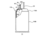
- FIG. 2 is a schematic diagram of the compressor of the air conditioner according to Embodiment 1 of the present invention.
- the compressor 11 has a housing 110 and an opening valve 40.
- the housing 110 has a top surface portion 110A and a body portion 110B.
- a refrigerant pipe 30 is connected to the top surface portion 110A.
- the opening valve 40 is a member for guiding the gas inside the compressor 11 to the outside.
- the opening valve 40 is installed as a separate component from the refrigerant pipe 30 in the end plate of the top surface portion 110A.
- FIG. 3 is a diagram showing a configuration of the opening valve of the air conditioner according to Embodiment 1 of the present invention.
- the opening valve 40 has a cylindrical portion 41 and a plate-like closing portion 42, and has a cylindrical shape as a whole.
- FIG. 3 shows a longitudinal section obtained by cutting the opening valve 40 along the axial center of the cylindrical portion 41.
- the first end 41 ⁇ / b> A of the cylindrical portion 41 is opened, and the second end 41 ⁇ / b> B of the cylindrical portion 41 is closed by the closing portion 42.
- the blocking part 42 has a flat plate shape.
- the opening valve 40 has a first end 41 ⁇ / b> A of the cylindrical portion 41 that opens toward the inside of the compressor 11, and a second end 41 ⁇ / b> B that faces the outside of the compressor 11.
- the compressor 11 is provided.
- the cylindrical portion 41 communicates with the compressor 11 through the first end portion 41A. With this configuration, the gas in the compressor 11 flows into the cylindrical portion 41.
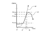
- FIG. 4 is a graph showing a pressure change inside the compressor of the air conditioner according to Embodiment 1 of the present invention.
- the function of the opening valve 40 will be described with reference to FIG.
- the vertical axis represents the pressure P inside the compressor 11, and the horizontal axis represents time T.
- the unit of the pressure P is MPa, and the unit of the time T is sec, that is, seconds.
- Pcomp is the design pressure of the air conditioner 1.
- P1max is the guaranteed pressure of the compressor 11.
- the guaranteed pressure P1max of the compressor 11 is about three times the design pressure Pcomp of the air conditioner 1.
- the compressor 11 is designed to ensure the guaranteed pressure P1max.
- P2max is the failure pressure of the compressor 11.
- the failure pressure P2max of the compressor 11 is a pressure at which the compressor 11 is damaged, and has a tolerance on the high pressure side with respect to the guaranteed pressure P1max. That is, if a pressure equal to or higher than the failure pressure P2max is applied to the inside of the compressor 11, the compressor 11 may be damaged and may not operate normally.
- the liquid side shut-off valve 16 is fully closed and the gas side shut-off valve 17 is fully opened to perform forced refrigerant operation.
- the cooling operation is performed with the gas side shut-off valve 17 fully opened in a state where the outdoor unit 10 and the indoor unit 20 are already separated, a large amount of air is mixed in the refrigerant circuit.
- air compression occurs inside the compressor 11, and the compressor 11 may suddenly rise until the pressure P of the compressor 11 exceeds the failure pressure P2max, and the compressor 11 may be damaged.
- a solid line L1 in FIG. 4 shows that a large amount of air is mixed in the refrigerant circuit while the air conditioner 1 is pumped down, and the pressure P of the compressor 11 suddenly increases from the state where the pressure Pcomp is lower than the design pressure Pcomp. In this embodiment, the pressure Pcomp is exceeded and the guaranteed pressure P1max is exceeded. In this case, if the high-pressure gas in the compressor 11 is not discharged out of the compressor 11, the pressure P of the compressor 11 continues to rise rapidly and exceeds the breakage pressure P2max as indicated by a thin broken line L2. .
- the opening valve 40 is configured to start opening when an opening pressure Pp that is higher than the guaranteed pressure P1max of the compressor 11 and lower than the breakage pressure P2max of the compressor 11 is applied. That is, when the pressure at which the gas flowing into the cylindrical portion 41 presses the closed portion 42 exceeds the guaranteed pressure P1max and reaches the opening pressure Pp due to the increase in the pressure in the compressor 11, the boundary between the cylindrical portion 41 and the closed portion 42 is reached.
- An opening is formed in the part, or in the closing part 42 itself.
- the cylindrical portion 41 serves as an open flow path that guides the gas inside the compressor 11 to the outside of the compressor 11.
- the opening valve 40 forms an open flow path that guides the gas inside the compressor 11 to the outside of the compressor 11 faster than the pressure P1 of the compressor 11 exceeds the guaranteed pressure P1max and then reaches the failure pressure P2max. It is configured to be.
- the time from when the pressure P of the compressor 11 exceeds the guaranteed pressure P1max to when it reaches the failure pressure P2max is t2 seconds-t1 seconds.
- the opening valve 40 is set so that the time from when the opening valve 40 starts to open until the cylindrical portion 41 functions as an open flow path is shorter than t2 seconds-t1 seconds. Is structured. With this configuration, the pressure P of the compressor 11 that suddenly increases and exceeds the guaranteed pressure P1max decreases without reaching the breakage pressure P2max, as shown by the thick broken line L3 in FIG.
- the opening valve 40 includes a cylindrical portion 41 and a closing portion 42, and the first end 41 ⁇ / b> A of the cylindrical portion 41 is communicated with the compressor 11.
- Table 1 shows the relationship between the rotational speed of the compressor 11 and the pressure increase rate when the compressor 11 having the casing 110 having an inner diameter of the body 110B of 107 mm and a plate thickness of 2.6 mm is used. It is a table.
- FIG. 5 is a graph showing the relationship between the rotational speed of the compressor 11 and the pressure increase rate based on the experimental results shown in Table 1.
- the pressure increase rate is about 200 MPa / sec at 60 rps which is a general rotation speed of the compressor. In order to release the pressure in the compressor 11 without damaging the casing of the compressor 11, the pressure release speed must exceed the pressure increase speed.
- Table 2 shows a case where the experiment was performed by changing the inner diameter of the cylindrical portion 41 of the opening valve 40 using the compressor 11 having the casing 110 having an inner diameter of the body portion 110B of 107 mm and a plate thickness of 2.6 mm.
- 4 is a table showing the relationship between the inner diameter of the opening valve 40 and the pressure release speed of the compressor 11.
- FIG. 6 is a graph showing the relationship between the inner diameter of the cylindrical portion 41 of the opening valve 40 and the pressure release speed based on the experimental results shown in Table 2. In the graph of FIG. 6, the pressure release speed is taken on the vertical axis, and the inner diameter of the cylindrical portion 41 is taken on the horizontal axis.
- the pressure release rate tends to exceed 200 MPa / sec. Therefore, if the inner diameter of the cylindrical portion 41 is set to about one-tenth or more of the inner diameter of the body portion 110B, the pressure release rate can exceed 200 MPa / sec, and the pressure increase rate can be exceeded.
- the casing of the compressor 11 or the opening valve 40 is damaged by the internal pressure, the initial energy of the jet is the damaged portion of the casing of the compressor 11 or the opening valve 40 at the initial stage of the damage if the internal pressure is the same. It is proportional to the length of the cracks that occur.
- the ratio of the initial energy due to the breakage of the casing of the compressor 11 and the opening of the opening valve 40 is the same as that of the casing of the compressor 11.
- Crack length generated in the casing of the compressor 11 due to breakage the diameter of the opening valve 40. That is, the smaller the diameter of the opening valve 40, the smaller the energy at the time of pressure release.
- the inner diameter of the cylindrical portion 41 of the first embodiment is set to about 1/10 or more of the inner diameter of the body portion 110B of the casing 110 of the compressor 11 of FIG. . More preferably, the inner diameter of the cylindrical portion 41 is not less than one tenth of the inner diameter of the body portion 110B of the casing 110 of the compressor 11, and the upper limit is set by allowable pressure release energy.
- Table 3 shows the closed portion 42 of the opening valve 40 and the inner diameter of the opening valve 40 when the above-described compressor 11 was used to change the thickness of the closing portion 42 of the opening valve 40 and the inner diameter of the cylindrical portion 41. It is a table
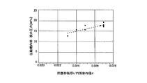
- FIG. FIG. 7 is a graph showing the relationship between the ratio of the plate thickness of the closed portion 42 to the inner diameter of the cylindrical portion 41 in the opening valve 40 and the maximum pressure inside the compressor 11 based on the experimental results shown in Table 3. Is. In the graph of FIG. 7, the maximum pressure inside the compressor 11 is taken on the vertical axis, and the ratio of the plate thickness of the closed portion 42 to the inner diameter of the cylindrical portion 41 is taken on the horizontal axis.
- the plate thickness of the closing portion 42 of the opening valve 40 of the first embodiment is set to about 1/10 of the plate thickness of the casing 110 of the compressor 11 shown in FIG. More preferably, the plate thickness of the closing portion 42 is one tenth or more of the plate thickness of the casing 110 of the compressor 11, and the upper limit is set by the maximum pressure determined by the ratio with the inner diameter of the cylindrical portion 41. ing. Further, the plate thickness of the cylindrical portion 41 is larger than the plate thickness of the closing portion 42. With the above configuration, the above-described function of the opening valve 40 is realized.
- the opening valve 40 in a state where the pressure of the compressor 11 is lower than the guaranteed pressure P1max, the opening valve 40 is closed by the closing portion 42, and the pressure of the compressor 11 exceeds the guaranteed pressure P1max.
- the opening valve 40 opens. And before the pressure of the compressor 11 reaches the failure pressure P2max, an open flow path is secured. Therefore, it is possible to prevent the compressor 11 from being damaged when the pressure inside the compressor 11 suddenly increases without affecting the functions and performances of the normal cooling operation and heating operation of the air conditioner 1.
- the rate of increase in the pressure P of the compressor 11 is faster than the rate at which high-pressure gas propagates to the components of the refrigerant circuit other than the compressor 11, the casing 110 of the compressor 11 is damaged. Can be prevented.
- the plate thickness of the cylindrical portion 41 of the opening valve 40 is thicker than the plate thickness of the closing portion 42, after the opening valve 40 is opened in response to a sudden pressure increase inside the compressor 11, The shape as is maintained.
- the air conditioner 1 is provided with a temperature sensor or a pressure sensor, and the operation stop of the compressor 11 is controlled based on the detection results of these sensors.
- the opening pressure Pp of the opening valve 40 is set to a value larger than the guaranteed pressure P1max and lower than the failure pressure P2max, and further exceeds the guaranteed pressure P1max before reaching the failure pressure P2max.
- An open channel is formed faster than it reaches. Therefore, according to this Embodiment 1, it can respond to the rapid pressure rise inside the compressor 11, and the failure
- the plate thickness of the cylindrical portion 41 is larger than the plate thickness of the closing portion 42. Therefore, when an opening is formed in the boundary between the closed portion 42 and the cylindrical portion 41 or in the closed portion 42 and the high-pressure gas is discharged to the outside of the compressor 11, the shape of the cylindrical portion 41 as an open flow path is maintained.
- FIG. 8 and 9 are diagrams showing another example of the opening valve of the air conditioner.
- An opening valve 50 shown in FIG. 8 has a cylindrical portion 51 and a closing portion 52.
- the first end 51 ⁇ / b> A of the cylindrical part 51 is opened, and the second end 51 ⁇ / b> B is closed by a closing part 52.
- the closing portion 52 is formed to be curved in a convex shape toward the inside of the cylindrical portion 51.
- the inner diameter of the cylindrical portion 51 is set to about one tenth of the inner diameter of the body portion 110B of the casing 110 of the compressor 11 shown in FIG.
- the inner diameter of the cylindrical portion 51 is set to 1/10 or more of the inner diameter of the body portion 110B of the casing 110 of the compressor 11, and the plate thickness of the closing portion 52 is set to that of the casing 110 of the compressor 11. It is set to 1/10 or more of the plate thickness. Further, the plate thickness of the cylindrical portion 51 is larger than the plate thickness of the closing portion 52.
- the opening valve 60 shown in FIG. The first end 61 ⁇ / b> A of the cylindrical part 61 is opened, and the second end 61 ⁇ / b> B is closed by a closing part 62.
- the closing portion 62 is formed to be curved in a convex shape toward the outside of the cylindrical portion 61.
- the inner diameter of the cylindrical portion 61 is set to about one-tenth of the inner diameter of the body portion 110B of the casing 110 of the compressor 11 shown in FIG. It is set to about 1/10 of the plate thickness of the casing 110 of the compressor 11 shown in FIG.
- the inner diameter of the cylindrical portion 61 is set to 1/10 or more of the inner diameter of the body portion 110B of the casing 110 of the compressor 11, and the plate thickness of the closing portion 62 is set to that of the casing 110 of the compressor 11. It is set to 1/10 or more of the plate thickness. Further, the plate thickness of the cylindrical portion 61 is thicker than the plate thickness of the closing portion 62.
- FIG. 10 is a schematic diagram of the compressor of the air conditioner according to Embodiment 2 of the present invention.
- symbol is attached
- FIG. 10 the opening valve 40 is a separate member from the refrigerant pipe 30, is provided on the side surface of the body 110 ⁇ / b> B of the compressor 11, and the first end 41 ⁇ / b> A of the cylindrical portion 41 is the compressor. 11 communicates with the inside.
- the opening valve 40 is disposed at a position higher than the oil level of the refrigerating machine oil stored in the lower part of the compressor 11 in the vertical direction of the body 110B. According to the second embodiment, the same effect as that of the first embodiment described above can be obtained.
- the opening valve 50 in FIG. 8 or the opening valve 60 in FIG. 9 may be provided on the side surface of the body 110B of the compressor 11 instead of the opening valve 40.
- FIG. 11 is a refrigeration cycle diagram of the air conditioner according to Embodiment 3 of the present invention.
- symbol is attached
- FIG. The high pressure region 70 is a region where the compressor 11 and the outdoor heat exchanger 14 are connected, and is a region where high pressure gas discharged from the compressor 11 flows.
- the opening valve 40 similar to that described in the first or second embodiment is provided in the refrigerant pipe 30 via the branch pipe 80 within the high pressure region 70.
- the branch pipe 80 is a branch pipe that branches in three directions.
- the branch pipe 80 is connected to a pipe connected to the discharge side of the compressor 11, a pipe connected to the muffler 12, and a first end 41 ⁇ / b> A shown in FIG. 3 of the opening valve 40. . Accordingly, similarly to the first and second embodiments described above, the cylindrical portion 41 communicates with the compressor 11 via the first end portion 41A. With this configuration, an open flow path for releasing high-pressure gas is secured outside the refrigerant circuit of the air conditioner 1.
- the high pressure region 70 includes the muffler 12 and the four-way switching valve 13, and the pressure increase in the high pressure region 70 when the gas refrigerant discharged from the compressor 11 flows into the high pressure region 70 is not uniform. Therefore, before the pressure at the location where the opening valve 40 is installed reaches the opening pressure Pp, the refrigerant flow rate and the distance from the discharge port of the compressor 11 are set so that the pressure in the compressor 11 does not exceed the guaranteed pressure P1max. Based on this, the installation location of the opening valve 40 in the refrigerant pipe 30 must be adjusted.
- the high pressure region 70 from the compressor 11 to the outdoor heat exchanger 14 may include the muffler 12.
- the muffler 12 is a component arranged at a position closest to the compressor 11 among the components located downstream of the compressor 11 in the refrigerant circuit when the air conditioner 1 is in cooling operation. In this case, if the high-pressure gas flows into the high-pressure region 70 during execution of the forced cooling operation by pumping down, the muffler 12 may be damaged. Therefore, in the third embodiment, in the refrigerant pipe 30, the opening valve 40 is provided via the branch pipe 80 in the pipe connecting the compressor 11 and the muffler 12. That is, when the pump down is executed, the opening valve 40 is arranged at a position upstream of the muffler 12 in the refrigerant circuit.
- the opening valve 40 is provided in the refrigerant pipe 30 forming the refrigerant circuit. Therefore, without changing the conventional configuration of the compressor 11, even if a sudden pressure increase occurs during execution of pump down, the compressor 11 can be prevented from being damaged.
- the opening valve 40 is arranged at a position upstream of the muffler 12 in the refrigerant circuit when the pump down is executed. Therefore, even if a sudden rise occurs during the pump down, not only the compressor 11 but also the muffler 12 can be prevented from being damaged.
- the opening valve 50 in FIG. 8 or the opening valve 60 in FIG. 9 may be attached to the branch pipe 80 instead of the opening valve 40.
- the branch pipe 80 may be a branch pipe that branches in three or more directions, and the opening valve 40 may be provided in one of the branched pipes.
Landscapes
- Engineering & Computer Science (AREA)
- Physics & Mathematics (AREA)
- Mechanical Engineering (AREA)
- Thermal Sciences (AREA)
- General Engineering & Computer Science (AREA)
- Air Conditioning Control Device (AREA)
- Applications Or Details Of Rotary Compressors (AREA)
- Other Air-Conditioning Systems (AREA)
Abstract
Description
図1は、本発明の実施の形態1に係る空気調和機の冷凍サイクル図である。空気調和機1は、室外機10と室内機20とを備えている。室外機10は、圧縮機11と、マフラー12と、四方向切換弁13と、室外熱交換器14と、冷媒減圧装置15と、液側閉鎖弁16と、ガス側閉鎖弁17と、室外送風機18とを有している。室内機20は、室内熱交換器21と、室内送風機22とを有している。圧縮機11、マフラー12、四方向切換弁13、室外熱交換器14、冷媒減圧装置15、液側閉鎖弁16、室内熱交換器21、及びガス側閉鎖弁17は、順次、冷媒配管30により接続されており、冷媒回路が形成されている。
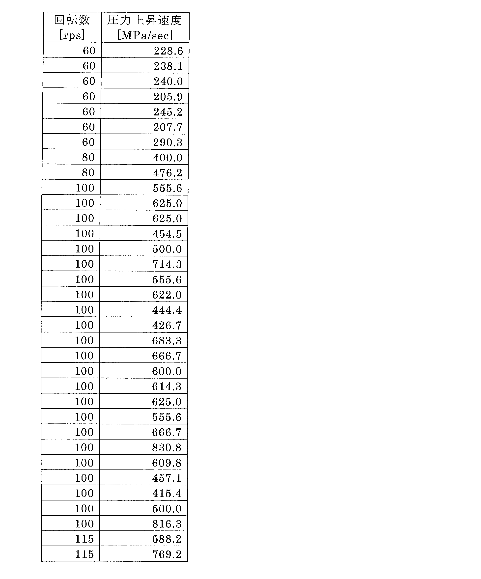
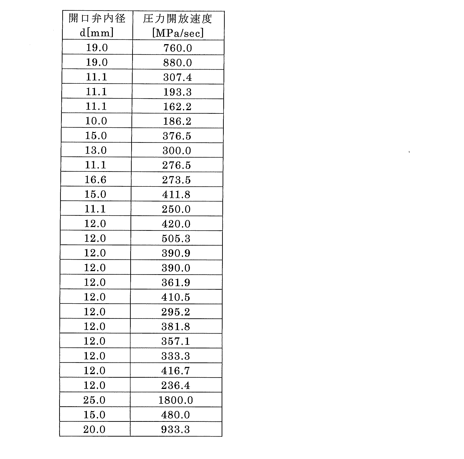
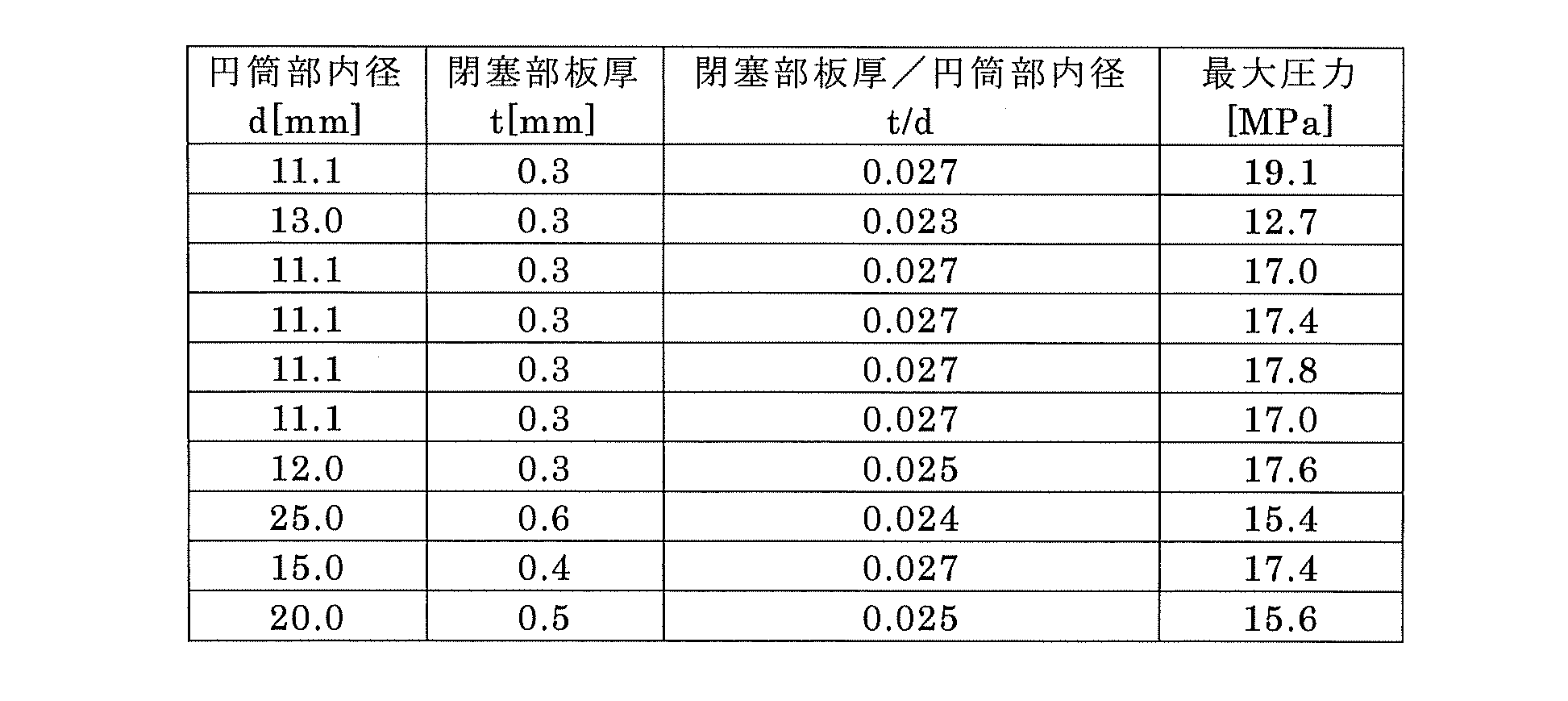
図10は、本発明の実施の形態2に係る空気調和機の圧縮機の概略図である。図10において、実施の形態1の圧縮機11の部材と同様の部材には同一の符号が付されている。図10に示すように、開口弁40は、冷媒配管30とは別体の部材であり、圧縮機11の胴部110Bの側面に設けられ、円筒部41の第1の端部41Aが圧縮機11の内部と連通している。開口弁40は、胴部110Bの上下方向において、圧縮機11の下部に貯留する冷凍機油の油面よりも高い位置に配置される。本実施の形態2によれば、上述の実施の形態1の効果と同様の効果が得られる。
図11は、本発明の実施の形態3に係る空気調和機の冷凍サイクル図である。図11において、実施の形態1の空気調和機1の部材と同様の部材には同一の符号が付されている。高圧領域70は、圧縮機11と室外熱交換器14とを接続する領域であり、圧縮機11から吐出される高圧ガスが流入する領域である。本実施の形態3では、高圧領域70の範囲内において、冷媒配管30に分岐管80を介して、実施の形態1又は2で説明したのと同様の開口弁40が設けられている。分岐管80は、3方向に分岐する分岐管である。分岐管80には、圧縮機11の吐出側に接続されている配管と、マフラー12に接続されている配管と、開口弁40の図3に示す第1の端部41Aとが接続されている。従って、上述の実施の形態1及び実施の形態2と同様、円筒部41は、第1の端部41Aを介して圧縮機11と連通している。この構成により、空気調和機1の冷媒回路の外部に高圧ガスを開放する開放流路が確保されている。
Claims (8)
- 圧縮機と、室外熱交換器とを有する室外機と、室内熱交換器を有する室内機と、前記圧縮機の内部の気体を外部に導くための開口弁とを備え、前記圧縮機、前記室外熱交換器、前記室内熱交換器が、冷媒配管で接続されて冷媒回路が形成されている空気調和機であって、
前記開口弁は、
円筒部と板状の閉塞部とを有し、前記円筒部の第1の端部は開放され、前記円筒部の第2の端部は前記閉塞部により閉塞され、前記円筒部は前記第1の端部を介して前記圧縮機と連通しており、
前記圧縮機の内部の圧力が、前記空気調和機の設計圧力より高く設定されている前記圧縮機の保証圧力より高く、かつ、前記圧縮機に破損が発生する圧力である破損圧力よりも低い開口圧力に達すると、前記円筒部と前記閉塞部の境界部分、若しくは前記閉塞部に開口が形成されるよう構成されている空気調和機。 - 前記保証圧力は、前記設計圧力の3倍に設定され、
前記開口弁は、前記圧縮機の内部の圧力が前記保証圧力を上回り、前記開口圧力に達して開口が形成された後、前記圧縮機の内部の圧力が前記保証圧力を上回ってから前記破損圧力に達するよりも速く、前記圧縮機の内部の気体を前記圧縮機の外部に導く開放流路が形成されるよう構成されている請求項1に記載の空気調和機。 - 前記圧縮機の内部の圧力が前記破損圧力に達する前に、前記円筒部が前記開放流路となるよう構成されている請求項2に記載の空気調和機。
- 前記円筒部の内径は、前記圧縮機の筐体の胴の内径の10分の1以上であり、前記閉塞部の板厚は前記圧縮機の前記筐体の板厚の10分の1以上である請求項3に記載の空気調和機。
- 前記円筒部の板厚は、前記閉塞部の板厚よりも厚い請求項4に記載の空気調和機。
- 前記開口弁は、前記圧縮機の前記筐体に設けられている請求項4又は5に記載の空気調和機。
- 前記開口弁は、前記冷媒配管において前記圧縮機の吐出側に接続されている配管に設けられている請求項1~5のいずれか一項に記載の空気調和機。
- 前記開口弁は、前記冷媒配管において、前記空気調和機が冷房運転されるとき前記冷媒回路において前記圧縮機の下流に位置する前記冷媒回路の構成部品のうち、前記圧縮機に最も近い位置に配置されている構成部品と、前記圧縮機とを接続する配管に設けられている請求項7に記載の空気調和機。
Priority Applications (5)
| Application Number | Priority Date | Filing Date | Title |
|---|---|---|---|
| PCT/JP2018/015533 WO2019198228A1 (ja) | 2018-04-13 | 2018-04-13 | 空気調和機 |
| CN201880092035.9A CN111936804B (zh) | 2018-04-13 | 2018-04-13 | 空调机 |
| KR1020207025295A KR102408552B1 (ko) | 2018-04-13 | 2018-04-13 | 공기 조화기 |
| CZ2020-511A CZ2020511A3 (cs) | 2018-04-13 | 2018-04-13 | Klimatizační zařízení |
| JP2020513035A JP6972316B2 (ja) | 2018-04-13 | 2018-04-13 | 空気調和機 |
Applications Claiming Priority (1)
| Application Number | Priority Date | Filing Date | Title |
|---|---|---|---|
| PCT/JP2018/015533 WO2019198228A1 (ja) | 2018-04-13 | 2018-04-13 | 空気調和機 |
Publications (1)
| Publication Number | Publication Date |
|---|---|
| WO2019198228A1 true WO2019198228A1 (ja) | 2019-10-17 |
Family
ID=68163192
Family Applications (1)
| Application Number | Title | Priority Date | Filing Date |
|---|---|---|---|
| PCT/JP2018/015533 Ceased WO2019198228A1 (ja) | 2018-04-13 | 2018-04-13 | 空気調和機 |
Country Status (5)
| Country | Link |
|---|---|
| JP (1) | JP6972316B2 (ja) |
| KR (1) | KR102408552B1 (ja) |
| CN (1) | CN111936804B (ja) |
| CZ (1) | CZ2020511A3 (ja) |
| WO (1) | WO2019198228A1 (ja) |
Citations (6)
| Publication number | Priority date | Publication date | Assignee | Title |
|---|---|---|---|---|
| JPS4987043U (ja) * | 1972-11-17 | 1974-07-27 | ||
| JPS53109225A (en) * | 1977-03-03 | 1978-09-22 | Black Sivalls & Bryson Inc | Safety pressure escaping device |
| JP2004353578A (ja) * | 2003-05-29 | 2004-12-16 | Calsonic Compressor Inc | 気体圧縮機の保護構造 |
| JP2007255858A (ja) * | 2006-03-27 | 2007-10-04 | Kawasaki Thermal Engineering Co Ltd | 吸収式冷温水機の保護装置 |
| JP2008298206A (ja) * | 2007-05-31 | 2008-12-11 | Osaka Gas Co Ltd | ラプチャディスク及びエンジン |
| JP2015114067A (ja) * | 2013-12-13 | 2015-06-22 | ダイキン工業株式会社 | 空気調和機 |
Family Cites Families (5)
| Publication number | Priority date | Publication date | Assignee | Title |
|---|---|---|---|---|
| JPH11125380A (ja) * | 1997-10-20 | 1999-05-11 | Mitsubishi Electric Corp | 空気調和装置 |
| JP2000130896A (ja) * | 1998-10-29 | 2000-05-12 | Sanden Corp | 安全装置を備えた空調装置 |
| KR20050102479A (ko) * | 2004-04-22 | 2005-10-26 | 주식회사 대우일렉트로닉스 | 히트펌프의 냉매과열도 개선구조 |
| JP2014214910A (ja) * | 2013-04-23 | 2014-11-17 | 三菱電機株式会社 | ヒートポンプ装置 |
| JP6805794B2 (ja) * | 2016-07-27 | 2020-12-23 | パナソニック株式会社 | 冷凍サイクル装置 |
-
2018
- 2018-04-13 KR KR1020207025295A patent/KR102408552B1/ko not_active Expired - Fee Related
- 2018-04-13 WO PCT/JP2018/015533 patent/WO2019198228A1/ja not_active Ceased
- 2018-04-13 CN CN201880092035.9A patent/CN111936804B/zh not_active Expired - Fee Related
- 2018-04-13 JP JP2020513035A patent/JP6972316B2/ja not_active Expired - Fee Related
- 2018-04-13 CZ CZ2020-511A patent/CZ2020511A3/cs unknown
Patent Citations (6)
| Publication number | Priority date | Publication date | Assignee | Title |
|---|---|---|---|---|
| JPS4987043U (ja) * | 1972-11-17 | 1974-07-27 | ||
| JPS53109225A (en) * | 1977-03-03 | 1978-09-22 | Black Sivalls & Bryson Inc | Safety pressure escaping device |
| JP2004353578A (ja) * | 2003-05-29 | 2004-12-16 | Calsonic Compressor Inc | 気体圧縮機の保護構造 |
| JP2007255858A (ja) * | 2006-03-27 | 2007-10-04 | Kawasaki Thermal Engineering Co Ltd | 吸収式冷温水機の保護装置 |
| JP2008298206A (ja) * | 2007-05-31 | 2008-12-11 | Osaka Gas Co Ltd | ラプチャディスク及びエンジン |
| JP2015114067A (ja) * | 2013-12-13 | 2015-06-22 | ダイキン工業株式会社 | 空気調和機 |
Also Published As
| Publication number | Publication date |
|---|---|
| CZ2020511A3 (cs) | 2020-10-14 |
| JP6972316B2 (ja) | 2021-11-24 |
| KR102408552B1 (ko) | 2022-06-14 |
| JPWO2019198228A1 (ja) | 2021-02-12 |
| CN111936804B (zh) | 2022-02-15 |
| KR20200118107A (ko) | 2020-10-14 |
| CN111936804A (zh) | 2020-11-13 |
Similar Documents
| Publication | Publication Date | Title |
|---|---|---|
| JP3109500B2 (ja) | 冷凍装置 | |
| US20190346191A1 (en) | Heat pump apparatus | |
| JP5295267B2 (ja) | 高圧冷凍システムにおける圧力除去 | |
| US12352484B2 (en) | Heat source unit and refrigeration device | |
| US11796238B2 (en) | Heat source unit and refrigeration apparatus | |
| US12123629B2 (en) | Heat source unit and refrigeration device having low-stage and high-stage compressors with four-way switching valve | |
| JP2011510255A (ja) | 高圧冷凍システムにおける圧力除去装置の取付 | |
| WO2000031479A1 (en) | Expansion device | |
| US20180363961A1 (en) | Air conditioner | |
| US11573039B2 (en) | Heat source unit and refrigeration apparatus | |
| US11512876B2 (en) | Refrigeration apparatus | |
| WO2019198228A1 (ja) | 空気調和機 | |
| WO2017175359A1 (ja) | 冷凍サイクル装置 | |
| CN110168295A (zh) | 流路切换装置、制冷循环回路及冰箱 | |
| JP2017116136A (ja) | 空気調和装置 | |
| WO2018100712A1 (ja) | 冷凍サイクル装置 | |
| WO2022185427A1 (ja) | 冷凍サイクル装置 | |
| JP6618638B2 (ja) | シングルスクリュー圧縮機及びそれを備えた冷凍空調装置 | |
| JP4661561B2 (ja) | 冷凍装置 | |
| JP7664742B2 (ja) | 空気調和機および圧力解放弁 | |
| WO2018186044A1 (ja) | 冷凍サイクル装置、ロータリ圧縮機 | |
| JP2024170901A (ja) | 冷凍サイクル装置 | |
| JP4720538B2 (ja) | 冷却加温システム | |
| JP2003302112A (ja) | 冷凍装置 | |
| JP4342194B2 (ja) | コンデンシングユニットの接続方法 |
Legal Events
| Date | Code | Title | Description |
|---|---|---|---|
| 121 | Ep: the epo has been informed by wipo that ep was designated in this application |
Ref document number: 18914408 Country of ref document: EP Kind code of ref document: A1 |
|
| ENP | Entry into the national phase |
Ref document number: 2020513035 Country of ref document: JP Kind code of ref document: A |
|
| ENP | Entry into the national phase |
Ref document number: 20207025295 Country of ref document: KR Kind code of ref document: A |
|
| NENP | Non-entry into the national phase |
Ref country code: DE |
|
| 122 | Ep: pct application non-entry in european phase |
Ref document number: 18914408 Country of ref document: EP Kind code of ref document: A1 |