WO2022185427A1 - 冷凍サイクル装置 - Google Patents
冷凍サイクル装置 Download PDFInfo
- Publication number
- WO2022185427A1 WO2022185427A1 PCT/JP2021/008056 JP2021008056W WO2022185427A1 WO 2022185427 A1 WO2022185427 A1 WO 2022185427A1 JP 2021008056 W JP2021008056 W JP 2021008056W WO 2022185427 A1 WO2022185427 A1 WO 2022185427A1
- Authority
- WO
- WIPO (PCT)
- Prior art keywords
- refrigerant
- pressure
- heat exchanger
- refrigerant circuit
- refrigeration cycle
- Prior art date
Links
- 238000005057 refrigeration Methods 0.000 title claims abstract description 52
- 239000003507 refrigerant Substances 0.000 claims abstract description 422
- 239000007788 liquid Substances 0.000 claims description 38
- 239000000155 melt Substances 0.000 claims description 10
- 230000005484 gravity Effects 0.000 claims description 7
- 238000010438 heat treatment Methods 0.000 description 45
- 238000001816 cooling Methods 0.000 description 37
- 238000010257 thawing Methods 0.000 description 25
- 230000007257 malfunction Effects 0.000 description 20
- 238000010586 diagram Methods 0.000 description 18
- 238000002844 melting Methods 0.000 description 18
- 230000008018 melting Effects 0.000 description 18
- 239000002826 coolant Substances 0.000 description 17
- 230000006837 decompression Effects 0.000 description 7
- 239000007787 solid Substances 0.000 description 6
- 230000033228 biological regulation Effects 0.000 description 4
- 239000013256 coordination polymer Substances 0.000 description 4
- 239000000463 material Substances 0.000 description 4
- 229920006395 saturated elastomer Polymers 0.000 description 4
- 239000011555 saturated liquid Substances 0.000 description 4
- 230000001105 regulatory effect Effects 0.000 description 3
- 230000009172 bursting Effects 0.000 description 2
- 230000005494 condensation Effects 0.000 description 2
- 238000009833 condensation Methods 0.000 description 2
- 230000007423 decrease Effects 0.000 description 2
- 230000008020 evaporation Effects 0.000 description 2
- 238000001704 evaporation Methods 0.000 description 2
- 238000000034 method Methods 0.000 description 2
- 230000002093 peripheral effect Effects 0.000 description 2
- 229910001369 Brass Inorganic materials 0.000 description 1
- 230000002159 abnormal effect Effects 0.000 description 1
- 239000000956 alloy Substances 0.000 description 1
- 229910045601 alloy Inorganic materials 0.000 description 1
- 239000010951 brass Substances 0.000 description 1
- 238000001514 detection method Methods 0.000 description 1
- 230000000694 effects Effects 0.000 description 1
- 239000012530 fluid Substances 0.000 description 1
- 230000017525 heat dissipation Effects 0.000 description 1
- 239000002184 metal Substances 0.000 description 1
- 230000000191 radiation effect Effects 0.000 description 1
- 238000010792 warming Methods 0.000 description 1
- XLYOFNOQVPJJNP-UHFFFAOYSA-N water Substances O XLYOFNOQVPJJNP-UHFFFAOYSA-N 0.000 description 1
Images


Classifications
-
- F—MECHANICAL ENGINEERING; LIGHTING; HEATING; WEAPONS; BLASTING
- F25—REFRIGERATION OR COOLING; COMBINED HEATING AND REFRIGERATION SYSTEMS; HEAT PUMP SYSTEMS; MANUFACTURE OR STORAGE OF ICE; LIQUEFACTION SOLIDIFICATION OF GASES
- F25B—REFRIGERATION MACHINES, PLANTS OR SYSTEMS; COMBINED HEATING AND REFRIGERATION SYSTEMS; HEAT PUMP SYSTEMS
- F25B40/00—Subcoolers, desuperheaters or superheaters
-
- F—MECHANICAL ENGINEERING; LIGHTING; HEATING; WEAPONS; BLASTING
- F25—REFRIGERATION OR COOLING; COMBINED HEATING AND REFRIGERATION SYSTEMS; HEAT PUMP SYSTEMS; MANUFACTURE OR STORAGE OF ICE; LIQUEFACTION SOLIDIFICATION OF GASES
- F25B—REFRIGERATION MACHINES, PLANTS OR SYSTEMS; COMBINED HEATING AND REFRIGERATION SYSTEMS; HEAT PUMP SYSTEMS
- F25B41/00—Fluid-circulation arrangements
- F25B41/20—Disposition of valves, e.g. of on-off valves or flow control valves
-
- F—MECHANICAL ENGINEERING; LIGHTING; HEATING; WEAPONS; BLASTING
- F25—REFRIGERATION OR COOLING; COMBINED HEATING AND REFRIGERATION SYSTEMS; HEAT PUMP SYSTEMS; MANUFACTURE OR STORAGE OF ICE; LIQUEFACTION SOLIDIFICATION OF GASES
- F25B—REFRIGERATION MACHINES, PLANTS OR SYSTEMS; COMBINED HEATING AND REFRIGERATION SYSTEMS; HEAT PUMP SYSTEMS
- F25B13/00—Compression machines, plants or systems, with reversible cycle
-
- F—MECHANICAL ENGINEERING; LIGHTING; HEATING; WEAPONS; BLASTING
- F25—REFRIGERATION OR COOLING; COMBINED HEATING AND REFRIGERATION SYSTEMS; HEAT PUMP SYSTEMS; MANUFACTURE OR STORAGE OF ICE; LIQUEFACTION SOLIDIFICATION OF GASES
- F25B—REFRIGERATION MACHINES, PLANTS OR SYSTEMS; COMBINED HEATING AND REFRIGERATION SYSTEMS; HEAT PUMP SYSTEMS
- F25B49/00—Arrangement or mounting of control or safety devices
- F25B49/02—Arrangement or mounting of control or safety devices for compression type machines, plants or systems
-
- F—MECHANICAL ENGINEERING; LIGHTING; HEATING; WEAPONS; BLASTING
- F25—REFRIGERATION OR COOLING; COMBINED HEATING AND REFRIGERATION SYSTEMS; HEAT PUMP SYSTEMS; MANUFACTURE OR STORAGE OF ICE; LIQUEFACTION SOLIDIFICATION OF GASES
- F25B—REFRIGERATION MACHINES, PLANTS OR SYSTEMS; COMBINED HEATING AND REFRIGERATION SYSTEMS; HEAT PUMP SYSTEMS
- F25B2313/00—Compression machines, plants or systems with reversible cycle not otherwise provided for
- F25B2313/027—Compression machines, plants or systems with reversible cycle not otherwise provided for characterised by the reversing means
- F25B2313/02741—Compression machines, plants or systems with reversible cycle not otherwise provided for characterised by the reversing means using one four-way valve
-
- F—MECHANICAL ENGINEERING; LIGHTING; HEATING; WEAPONS; BLASTING
- F25—REFRIGERATION OR COOLING; COMBINED HEATING AND REFRIGERATION SYSTEMS; HEAT PUMP SYSTEMS; MANUFACTURE OR STORAGE OF ICE; LIQUEFACTION SOLIDIFICATION OF GASES
- F25B—REFRIGERATION MACHINES, PLANTS OR SYSTEMS; COMBINED HEATING AND REFRIGERATION SYSTEMS; HEAT PUMP SYSTEMS
- F25B2400/00—General features or devices for refrigeration machines, plants or systems, combined heating and refrigeration systems or heat-pump systems, i.e. not limited to a particular subgroup of F25B
- F25B2400/13—Economisers
-
- F—MECHANICAL ENGINEERING; LIGHTING; HEATING; WEAPONS; BLASTING
- F25—REFRIGERATION OR COOLING; COMBINED HEATING AND REFRIGERATION SYSTEMS; HEAT PUMP SYSTEMS; MANUFACTURE OR STORAGE OF ICE; LIQUEFACTION SOLIDIFICATION OF GASES
- F25B—REFRIGERATION MACHINES, PLANTS OR SYSTEMS; COMBINED HEATING AND REFRIGERATION SYSTEMS; HEAT PUMP SYSTEMS
- F25B2500/00—Problems to be solved
- F25B2500/18—Optimization, e.g. high integration of refrigeration components
Definitions
- the present disclosure relates to a refrigeration cycle device.
- Patent Document 1 discloses a refrigeration cycle apparatus including an accumulator provided in a low-pressure side pipe between an evaporator and a compressor, and a fusible plug capable of opening the low-pressure side pipe provided with the accumulator to the atmosphere. is described.
- one object of the present disclosure is to provide a refrigeration cycle apparatus having a structure capable of suppressing malfunction of a fusible plug while suppressing an increase in the number of parts. do.
- One aspect of the refrigeration cycle device in the present disclosure is a first refrigerant circuit in which a compressor, a condenser, an internal heat exchanger, a first pressure reducing device, and an evaporator are annularly connected, and the first refrigerant a second refrigerant circuit that branches from a branch portion of the circuit and merges with the confluence portion of the first refrigerant circuit on the suction side of the compressor via the internal heat exchanger; and pressure relief means provided between the branch and the internal heat exchanger.
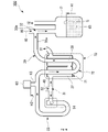
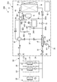
- FIG. 1 is a refrigerant circuit diagram showing a schematic configuration of a refrigeration cycle device according to Embodiment 1.
- FIG. FIG. 2 is a diagram showing a bypass refrigerant circuit according to Embodiment 1;
- FIG. FIG. 2 shows a fusible plug according to Embodiment 1;
- 4 is a cross-sectional view showing the fusible plug in Embodiment 1, taken along the line IV-IV in FIG. 3.
- FIG. FIG. 4 is a Mollier diagram showing an example of a state change of a refrigerant during cooling operation;
- FIG. 4 is a Mollier diagram showing an example of a state change of a refrigerant during heating operation;
- FIG. 2 is a refrigerant circuit diagram showing a schematic configuration of a refrigeration cycle device according to Embodiment 2;
- FIG. 10 is a refrigerant circuit diagram showing a schematic configuration of a refrigeration cycle device according to Embodiment 3;
- FIG. 1 is a refrigerant circuit diagram showing a schematic configuration of a refrigeration cycle device 100 according to Embodiment 1.
- FIG. Refrigeration cycle device 100 in Embodiment 1 is an air conditioner.
- the refrigeration cycle device 100 includes an outdoor unit 10 installed outdoors, an indoor unit 20 installed indoors, a circulation refrigerant circuit 30 that circulates a refrigerant 40, and a controller 18. , provided.
- the circulation refrigerant circuit 30 corresponds to the "first refrigerant circuit".
- the refrigeration cycle device 100 can adjust the temperature of the indoor air by exchanging heat between the refrigerant 40 flowing in the circulation refrigerant circuit 30 and the indoor air in which the indoor unit 20 is arranged.
- the refrigerating cycle device 100 performs a cooling operation for cooling the indoor air in which the indoor unit 20 is arranged, a heating operation for warming the indoor air in which the indoor unit 20 is arranged, and an outdoor heat exchanger 13 of the outdoor unit 10 described later. and a defrosting operation that is performed to remove the frost that has occurred.
- the type of coolant 40 is not particularly limited. Examples of the refrigerant 40 include R410A.
- the control device 18 is, for example, a control device that controls the entire refrigeration cycle device 100 .
- the control device 18 is provided inside the housing 11 of the outdoor unit 10 .
- the control device 18 can switch the operation of the refrigeration cycle device 100 between cooling operation, heating operation, and defrosting operation.
- the circulating refrigerant circuit 30 includes the compressor 12, the four-way valve 16, the indoor heat exchanger 22, the indoor expansion valve 24, the internal heat exchanger 70, the outdoor expansion valve, in the flow direction of the refrigerant 40 during the heating operation. 51, the outdoor heat exchanger 13, and the pressure vessel 17 are annularly connected in this order via refrigerant pipes.
- Embodiment 1 the compressor 12, the four-way valve 16, the internal heat exchanger 70, the outdoor expansion valve 51, the outdoor heat exchanger 13, and the pressure vessel 17 are housed inside the housing 11 of the outdoor unit 10.
- An outdoor fan 15 that blows air to the outdoor heat exchanger 13 is provided inside the housing 11 of the outdoor unit 10 .
- the indoor heat exchanger 22 and the indoor expansion valve 24 are housed inside the housing 21 of the indoor unit 20 .
- An indoor fan 23 that blows air to the indoor heat exchanger 22 is provided inside the housing 21 of the indoor unit 20 .
- the outdoor unit 10 and the indoor unit 20 are connected by pipes 35 and 36 that are part of the refrigerant pipes of the circulation refrigerant circuit 30 .
- the pipe 35 connects a portion of the refrigerant pipe of the circulation refrigerant circuit 30 located inside the outdoor unit 10 that is connected to the internal heat exchanger 70 and the refrigerant pipe of the circulation refrigerant circuit 30 located inside the indoor unit 20 .
- the pipe 36 connects a portion of the refrigerant pipe of the circulation refrigerant circuit 30 located inside the outdoor unit 10 that is connected to the four-way valve 16 and the refrigerant pipe of the circulation refrigerant circuit 30 located inside the indoor unit 20 .
- connection valve 52 is provided between the internal heat exchanger 70 and the pipe 35 in the circulation refrigerant circuit 30 .
- a connection valve 53 is provided between the four-way valve 16 and the pipe 36 in the circulation refrigerant circuit 30 .
- the connection valves 52 and 53 are provided inside the housing 11 of the outdoor unit 10 .
- the compressor 12 is a fluid machine that compresses the sucked low-pressure refrigerant 40 and discharges it as a high-pressure refrigerant 40 .
- the compressor 12 is, for example, a capacity-controllable inverter compressor.
- the refrigerant 40 circulates in the circulation refrigerant circuit 30 by driving the compressor 12 .
- the four-way valve 16 is arranged on the discharge side of the compressor 12 .
- the four-way valve 16 can reverse the direction of the refrigerant 40 flowing through the circulation refrigerant circuit 30 by switching a part of the path of the circulation refrigerant circuit 30 .
- the path connected by the four-way valve 16 is the path indicated by the solid line in the four-way valve 16 in FIG. 1
- the refrigerant 40 flows in the circulation refrigerant circuit 30 in the direction indicated by the solid arrow in FIG.
- the path connected by the four-way valve 16 is the path indicated by the dashed line in the four-way valve 16 in FIG. 1
- the refrigerant 40 flows in the circulation refrigerant circuit 30 in the direction indicated by the dashed arrow in FIG.
- the flow of the refrigerant 40 indicated by the solid line in FIG. 1 is the direction in which the refrigerant 40 flows during cooling operation.
- the flow of the refrigerant 40 indicated by the dashed line in FIG. 1 is the direction in which the refrigerant 40 flows during the heating operation.
- a low-temperature, low-pressure refrigerant 40 is supplied into the indoor heat exchanger 22 .
- a high-temperature, high-pressure refrigerant 40 is supplied into the indoor heat exchanger 22 .
- the outdoor heat exchanger 13 is a heat exchanger that functions as an evaporator during heating operation and as a condenser during cooling operation. In the outdoor heat exchanger 13 , heat exchange is performed between the refrigerant 40 flowing inside the outdoor heat exchanger 13 and the air (outside air) blown by the outdoor fan 15 .
- a temperature sensor 14 is attached to the outdoor heat exchanger 13 in the first embodiment.
- the indoor heat exchanger 22 is a heat exchanger that functions as a condenser during heating operation and as an evaporator during cooling operation. In the indoor heat exchanger 22 , heat exchange is performed between the refrigerant 40 flowing inside the indoor heat exchanger 22 and the air (indoor air) blown by the indoor blower 23 .
- the pressure vessel 17 is arranged on the suction side of the compressor 12 .
- the pressure vessel 17 can store excess refrigerant 40 inside.
- a liquid coolant 40 is stored in the pressure vessel 17 .
- the pressure vessel 17 in Embodiment 1 is an accumulator. Note that the pressure vessel 17 may be any vessel as long as it can store the excessive refrigerant 40 .
- the outdoor expansion valve 51 is an electronic linear expansion valve whose opening can be continuously adjusted.
- the degree of opening of the outdoor expansion valve 51 is adjusted by the controller 18, for example.
- the degree of opening of the outdoor expansion valve 51 is fully opened during cooling operation. Accordingly, during the cooling operation, the outdoor expansion valve 51 does not contribute to the state change of the refrigerant 40 passing through the outdoor expansion valve 51 .
- the outdoor expansion valve 51 decompresses and expands the refrigerant 40 after passing through the indoor expansion valve 24 .
- the refrigerant 40 that flows into the outdoor expansion valve 51 after passing through the indoor expansion valve 24 during heating operation is liquid refrigerant or gas-liquid two-phase refrigerant.
- the indoor expansion valve 24 in Embodiment 1 is an electronic linear expansion valve whose opening can be continuously adjusted.
- the degree of opening of the indoor expansion valve 24 is adjusted by the controller 18, for example.
- the indoor expansion valve 24 decompresses and expands the liquid refrigerant 40 condensed in the outdoor heat exchanger 13 at least during cooling operation.
- the outdoor expansion valve 51 and the indoor expansion valve 24 correspond to the "first pressure reducing device".
- the refrigeration cycle device 100 further includes a bypass refrigerant circuit 33 connected to the circulation refrigerant circuit 30 .
- the bypass refrigerant circuit 33 branches from a part of the circulation refrigerant circuit 30 and joins another part of the circulation refrigerant circuit 30 .
- the bypass refrigerant circuit 33 includes a branch portion 31 located between the connection valve 52 and the internal heat exchanger 70 in the circulation refrigerant circuit 30, and the pressure vessel 17 and the four-way valve 16 in the circulation refrigerant circuit 30. and the confluence portion 32 located between the .
- the confluence portion 32 is positioned in front of the pressure vessel 17 .
- Bypass refrigerant circuit 33 passes through internal heat exchanger 70 .
- the bypass refrigerant circuit 33 is a circuit that branches from the branch portion 31 of the circulation refrigerant circuit 30 and merges with the junction portion 32 of the circulation refrigerant circuit 30 on the suction side of the compressor 12 via the internal heat exchanger 70. .
- the bypass refrigerant circuit 33 corresponds to the "second refrigerant circuit".
- the refrigerant 40 flowing through the circulating refrigerant circuit 30 during cooling operation passes through the connection valve 52 and the indoor expansion valve 24 at the branch portion 31 and flows into the indoor heat exchanger 22 . , and the refrigerant 40 flowing to the bypass refrigerant circuit 33 .
- the refrigerant 40 flowing into the bypass refrigerant circuit 33 As indicated by solid arrows in FIG. 1 , the refrigerant 40 flowing through the circulating refrigerant circuit 30 during cooling operation passes through the connection valve 52 and the indoor expansion valve 24 at the branch portion 31 and flows into the indoor heat exchanger 22 . , and the refrigerant 40 flowing to the bypass refrigerant circuit 33 .
- the dashed arrow in FIG. and the refrigerant 40 flowing into the bypass refrigerant circuit 33 .
- the refrigerant 40 branched into the bypass refrigerant circuit 33 at the branching portion 31 during the heating operation is the refrigerant 40 flowing through the circulation refrigerant circuit 30 that passes through the outdoor heat exchanger 13 and the four-way valve 16 and heads to the pressure vessel 17. 40 and merge at the junction 32 .
- the branch portion 31 is positioned between the connection valve 52 and the internal heat exchanger 70 in Embodiment 1, the present invention is not limited to this.
- the branch portion 31 may be located between the internal heat exchanger 70 and the outdoor expansion valve 51, for example.
- the bypass refrigerant circuit 33 is provided with an expansion valve 54 and a fusible plug 60 .
- the expansion valve 54 is an electronic linear expansion valve whose degree of opening can be continuously adjusted. The degree of opening of the expansion valve 54 is adjusted by the controller 18, for example.
- the expansion valve 54 corresponds to a "second pressure reducing device".
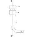
- FIG. 2 is a diagram showing the bypass refrigerant circuit 33 of Embodiment 1.
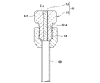
- FIG. 3 shows the fusible plug 60 according to Embodiment 1.
- FIG. 4 is a cross-sectional view showing the fusible plug 60 according to Embodiment 1, and is a cross-sectional view taken along line IV-IV in FIG.
- the direction of gravity is indicated by the Z-axis.
- the direction in which the arrow of the Z-axis points is the upper direction of gravity
- the direction opposite to the direction in which the arrow of the Z-axis points is the lower direction of gravity.
- illustration of the detailed piping shape and the like inside the pressure vessel 17 is omitted.
- the fusible plug 60 is located between the expansion valve 54 of the bypass refrigerant circuit 33 and an inner pipe 72 of the internal heat exchanger 70, which will be described later.
- the fusible plug 60 is attached to a branch pipe 63 connected to the refrigerant pipe of the bypass refrigerant circuit 33 .
- the fusible plug 60 in Embodiment 1 is fixed to the distal end portion of the branch pipe 63 with a flare nut 64 .
- the fusible plug 60 may be fixed to the branch pipe 63 by, for example, a tapered pipe screw.
- the fusible plug 60 has a substantially cylindrical plug body portion 61 and a fusible portion 62 that melts at a temperature equal to or higher than a predetermined value.
- the material forming the plug portion 61 is, for example, brass.
- the plug body portion 61 has a small diameter portion 61a and a large diameter portion 61b having an outer diameter larger than that of the small diameter portion 61a.
- An outer peripheral surface of the small-diameter portion 61 a is provided with a male thread portion that is screwed into a female thread portion provided on the inner peripheral surface of the flare nut 64 .
- One end of the small diameter portion 61 a is in contact with the distal end of the branch pipe 63 .
- a large diameter portion 61b is connected to the other end of the small diameter portion 61a.
- the plug body portion 61 has a through hole 61c that penetrates the plug body portion 61 in the axial direction of the plug body portion 61 .
- One end of the through hole 61 c opens inside the branch pipe 63 .
- the other end of the through-hole 61 c opens to the outside of the branch pipe 63 .
- the other end of the through hole 61c opens into the atmospheric pressure atmosphere.
- the fusible portion 62 is filled in the through hole 61c. Therefore, the through hole 61c is closed by the fusible portion 62 .
- the material forming the fusible portion 62 is an alloy with a relatively low melting temperature.
- the melting temperature of the material forming the fusible portion 62 is lower than the melting temperature of the material forming the plug portion 61 .
- the melting temperature of the fusible part 62 is set to, for example, the critical temperature of the coolant 40 to be used or less. As an example, when R410A is used as the coolant 40, the melting temperature of the fusible portion 62 is set to 70°C, which is lower than 71.4°C, because the critical temperature of R410A is 71.4°C.
- the fusible part 62 melts, for example, when the ambient temperature of the pressure vessel 17 rises abnormally and the inside of the pressure vessel 17 becomes high temperature and high pressure.
- the through hole 61c is opened, and the inside of the branch pipe 63 and the outside of the branch pipe 63 are connected.
- the pressure in the bypass refrigerant circuit 33 and the pressure in the circulation refrigerant circuit 30 can be released to the atmospheric pressure via the branch pipe 63 . Therefore, the pressure in the pressure vessel 17 can be released to the atmospheric pressure and released to the outside. Therefore, problems such as the pressure vessel 17 bursting can be suppressed.
- the height H2 of the fusible plug 60 is higher than the height H1 of the liquid surface S of the liquid refrigerant 40 stored in the pressure vessel 17 in the direction of gravity.
- pressure vessel 17 and fusible plug 60 are directly connected only by refrigerant pipe 39 .
- the refrigerant pipe 39 is a pipe extending from the fusible plug 60 to the pressure vessel 17 and includes a branch pipe 63 and an inner pipe 72 . No components other than the refrigerant pipe 39 are provided between the pressure vessel 17 and the fusible plug 60 .
- Components other than the refrigerant pipe 39 include, for example, a valve member such as an electronic expansion valve and a check valve that can block a part of the refrigerant pipe, and a capillary. That is, in Embodiment 1, the refrigerant pipe 39 connecting the pressure vessel 17 and the fusible plug 60 is provided with neither a valve member nor a capillary.
- heat exchange is performed between the refrigerant 40 flowing inside the circulation refrigerant circuit 30 and the refrigerant 40 flowing inside the bypass refrigerant circuit 33 .
- the refrigerant 40 flowing between the branch portion 31 and the outdoor expansion valve 51 in the circulation refrigerant circuit 30 and the expansion valve 54 and the confluence portion 32 in the bypass refrigerant circuit 33 Heat exchange is performed with the refrigerant 40 flowing between , that is, the refrigerant 40 after being decompressed by the expansion valve 54 .
- the internal heat exchanger 70 in Embodiment 1 is a double-tube heat exchanger having an outer tube 71 and an inner tube 72 passing through the outer tube 71 .
- the outer tube 71 and the inner tube 72 extend in a substantially U-shape.
- a folded portion of the U-shaped inner tube 72 is exposed to the outside of the outer tube 71 .
- the outer tube 71 and the inner tube 72 form an outer flow path portion 37 provided between the outer tube 71 and the inner tube 72 .
- the inner surface of the outer channel portion 37 is composed of the inner surface of the outer tube 71 and the outer surface of the inner tube 72 .
- the outer flow path portion 37 forms part of the refrigerant circulation circuit 30 .
- the inner channel portion 38 is formed by the inner tube 72 .
- the inner surface of the inner flow path portion 38 is configured by the inner surface of the inner pipe 72 .
- the inner flow path portion 38 forms part of the bypass refrigerant circuit 33 .
- a medium-pressure or low-pressure refrigerant 40 depressurized by an expansion valve 54 flows through the inner flow path portion 38 .
- the outer flow path portion 37 may form part of the bypass refrigerant circuit 33 and the inner flow path portion 38 may form part of the circulation refrigerant circuit 30 .
- the internal heat exchanger 70 is not limited to a double-pipe heat exchanger, and may be a plate heat exchanger, for example.
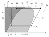
- FIG. 5 is a Mollier diagram showing an example of the state change of the refrigerant 40 during cooling operation.
- FIG. 6 is a Mollier diagram showing an example of the state change of the refrigerant 40 during heating operation.
- the horizontal axis indicates the specific enthalpy of the refrigerant 40 and the vertical axis indicates the pressure of the refrigerant 40 .
- the Mollier diagrams shown in FIGS. 5 and 6 show a saturated liquid line SL, a saturated vapor line SS, and a critical point CP.
- the saturated liquid line SL and the saturated steam line SS are connected at the critical point CP.
- the refrigerant 40 In the region GA where the pressure of the refrigerant 40 is equal to or less than the pressure at the critical point CP and the specific enthalpy of the refrigerant 40 is higher than the saturated vapor line SS, the refrigerant 40 is in a gaseous state, that is, a gas refrigerant. . In the region MA surrounded by the saturated liquid line SL and the saturated vapor line SS, the refrigerant 40 is in a state in which gas and liquid are mixed, that is, a gas-liquid two-phase refrigerant.
- the refrigerant 40 In a region LA where the pressure of the refrigerant 40 is equal to or lower than the pressure at the critical point CP and the specific enthalpy of the refrigerant 40 is lower than the saturated liquid line SL, the refrigerant 40 is in a liquid state, that is, a liquid refrigerant. .
- Graphs indicated by solid lines in each of the Mollier diagrams of FIGS. Graphs indicated by dashed lines in the Mollier diagrams of FIGS. 5 and 6 show state changes of the refrigerant 40 flowing through the bypass refrigerant circuit 33 .
- the refrigerant 40 compressed by the compressor 12 during cooling operation becomes a high-temperature and high-pressure gas refrigerant.
- the state of refrigerant 40 after being compressed by compressor 12 is indicated by point Pa in FIG.
- refrigerant 40 compressed by compressor 12 during cooling operation flows through four-way valve 16 into outdoor heat exchanger 13 .
- the outdoor heat exchanger 13 functions as a condenser.
- the refrigerant 40 condensed in the outdoor heat exchanger 13 to become a high-pressure liquid refrigerant passes through the outer flow path portion 37 of the internal heat exchanger 70.
- the branch 31 is reached.
- part of the refrigerant 40 is branched to the bypass refrigerant circuit 33 .
- the remaining refrigerant 40 flows through the connection valve 52 and into the indoor expansion valve 24 .
- the refrigerant 40 branched to the bypass refrigerant circuit 33 is decompressed by the expansion valve 54 to become a low-pressure gas-liquid two-phase refrigerant, and flows into the inner flow path portion 38 of the internal heat exchanger 70 .
- the state of the refrigerant 40 after being decompressed by the expansion valve 54 is indicated by point Pf in FIG.
- the specific enthalpy of the refrigerant 40 that has passed through the outer passage portion 37 is reduced by heat exchange with the low-pressure gas-liquid two-phase refrigerant that has flowed into the inner passage portion 38 .
- the state of the coolant 40 after passing through the outer channel portion 37 is indicated by point Pc in FIG.
- the specific enthalpy of the refrigerant 40 that has flowed into the inner channel portion 38 increases due to heat exchange with the high-pressure liquid refrigerant that has flowed into the outer channel portion 37 .
- the refrigerant 40 that has passed through the inner flow path portion 38 becomes a gas-liquid two-phase refrigerant or a gas refrigerant with a high degree of dryness.
- the state of the coolant 40 after passing through the inner channel portion 38 is indicated by a point Pe in FIG. In the example of FIG. 5, the refrigerant 40 is a gas refrigerant at the point Pe.
- the refrigerant 40 that has flowed into the indoor expansion valve 24 is decompressed and becomes a low-pressure gas-liquid two-phase refrigerant.
- the state of the refrigerant 40 after passing through the indoor expansion valve 24 and becoming a low-pressure two-phase refrigerant is indicated by point Pd in FIG.
- the refrigerant 40 that has become a low-pressure gas-liquid two-phase refrigerant in the indoor expansion valve 24 flows into the indoor heat exchanger 22 .
- the indoor heat exchanger 22 functions as an evaporator.
- the indoor heat exchanger 22 heat is exchanged between the refrigerant 40 flowing inside the indoor heat exchanger 22 and the air (indoor air) blown by the indoor blower 23, and the evaporation heat of the refrigerant 40 is is absorbed from the air sent by the indoor blower 23.
- the refrigerant 40 that has flowed into the indoor heat exchanger 22 evaporates and becomes a low-pressure gas refrigerant.
- the refrigerant 40 after passing through the indoor heat exchanger 22 and becoming a low-pressure gas refrigerant is indicated by a point Pe in FIG.
- the refrigerant 40 that has passed through the indoor heat exchanger 22 to become a low-pressure gas refrigerant passes through the four-way valve 16 and enters the bypass refrigerant circuit at the confluence portion 32. It joins the refrigerant 40 that has passed through 33 , passes through the pressure vessel 17 and is sucked into the compressor 12 . The refrigerant 40 sucked into the compressor 12 is compressed by the compressor 12 and becomes high-temperature and high-pressure gas refrigerant again.
- the state of the refrigerant 40 flowing through the portion of the bypass refrigerant circuit 33 where the fusible plug 60 is provided is indicated by point Pf in FIG.
- the temperature of the refrigerant 40 at the point Pf is about 5° C. or higher and 18° C. or lower, although it depends on the operating state. Therefore, melting of the fusible portion 62 of the fusible plug 60 due to the heat of the refrigerant 40 is suppressed during cooling operation. Therefore, malfunction of the fusible plug 60 is suppressed during cooling operation.
- the refrigerant 40 compressed by the compressor 12 becomes a high-temperature, high-pressure gas refrigerant during the heating operation as well as during the cooling operation.
- the state of refrigerant 40 after being compressed by compressor 12 is indicated by point Pg in FIG.
- Refrigerant 40 compressed by compressor 12 flows into indoor heat exchanger 22 through four-way valve 16, as indicated by a dashed arrow in FIG.
- the indoor heat exchanger 22 functions as a condenser. That is, in the indoor heat exchanger 22 during the heating operation, heat is exchanged between the gaseous refrigerant 40 flowing inside the indoor heat exchanger 22 and the air (indoor air) blown by the indoor blower 23.
- the heat of condensation of the refrigerant 40 is radiated to the air blown by the indoor blower 23 .
- the refrigerant 40 that has flowed into the indoor heat exchanger 22 is condensed into a high-pressure liquid refrigerant.
- the air blown by the indoor blower 23 is heated by the heat dissipation action of the refrigerant 40 and becomes warm air.
- the state of the refrigerant 40 after being condensed in the indoor heat exchanger 22 is indicated by point Ph in FIG.
- the refrigerant 40 condensed in the indoor heat exchanger 22 to become a high-pressure liquid refrigerant flows into the indoor expansion valve 24 and is decompressed by the indoor expansion valve 24. and becomes medium-pressure liquid refrigerant.
- the state of the intermediate-pressure refrigerant 40 after being decompressed by the indoor expansion valve 24 is indicated by point Pi in FIG.
- the refrigerant 40 that has flowed out of the indoor expansion valve 24 is decompressed by pressure loss when passing through the pipe 35, and flows into the outdoor unit 10 in the state of liquid refrigerant or gas-liquid two-phase refrigerant.
- the state of the refrigerant 40 when it flows into the outdoor unit 10 after passing through the pipe 35 from the indoor expansion valve 24 is indicated by a point Pj in FIG.
- the refrigerant 40 is a gas-liquid two-phase refrigerant at the point Pj.
- part of the refrigerant 40 that has flowed into the outdoor unit 10 is branched to the bypass refrigerant circuit 33 at the branch portion 31 during heating operation.
- the rest of the refrigerant 40 flows into the outer channel portion 37 of the internal heat exchanger 70 .
- the refrigerant 40 branched to the bypass refrigerant circuit 33 is decompressed by the expansion valve 54 to become a low-pressure gas-liquid two-phase refrigerant, and flows into the inner flow path portion 38 of the internal heat exchanger 70 .
- the state of the refrigerant 40 after being decompressed by the expansion valve 54 is indicated by point Po in FIG.
- the specific enthalpy of the refrigerant 40 that has passed through the outer passage portion 37 is reduced by heat exchange with the low-pressure gas-liquid two-phase refrigerant that has flowed into the inner passage portion 38 .
- the state of the coolant 40 after passing through the outer channel portion 37 is indicated by a point Pk in FIG.
- the refrigerant 40 changes from the gas-liquid two-phase refrigerant to the liquid refrigerant when the state of the point Pj changes to the state of the point Pk.
- the specific enthalpy of the refrigerant 40 that has flowed into the inner channel portion 38 increases due to heat exchange with the refrigerant 40 that has flowed into the outer channel portion 37 .
- the refrigerant 40 that has passed through the inner flow path portion 38 becomes a gas-liquid two-phase refrigerant or a gas refrigerant with a high degree of dryness.
- the state of the coolant 40 after passing through the inner channel portion 38 is indicated by point Pp in FIG. In the example of FIG. 6, the refrigerant 40 remains the gas-liquid two-phase refrigerant at the point Pp.
- the refrigerant 40 that has passed through the outer flow passage portion 37 is decompressed by the outdoor expansion valve 51 to become a low-pressure gas-liquid two-phase refrigerant, thereby exchanging outdoor heat. It flows into vessel 13 .
- the state of the refrigerant 40 after being decompressed by the outdoor expansion valve 51 is indicated by a point Pm in FIG.
- the outdoor heat exchanger 13 functions as an evaporator.
- the refrigerant 40 that has passed through the outdoor heat exchanger 13 and has become a low-pressure gas refrigerant passes through the four-way valve 16 and enters the bypass refrigerant circuit at the confluence portion 32. It joins the refrigerant 40 that has passed through 33 , passes through the pressure vessel 17 and is sucked into the compressor 12 . The refrigerant 40 sucked into the compressor 12 is compressed by the compressor 12 and becomes high-temperature and high-pressure gas refrigerant again.
- the state of the refrigerant 40 flowing through the portion of the bypass refrigerant circuit 33 where the fusible plug 60 is provided is indicated by point Po in FIG.
- the temperature of the refrigerant 40 at the point Po is about 10° C. or higher and 18° C. or lower, depending on the operating state. Therefore, melting of the fusible portion 62 of the fusible plug 60 due to the heat of the refrigerant 40 is suppressed even during the heating operation. Therefore, malfunction of the fusible plug 60 is suppressed even during the heating operation.
- Defrosting operation is performed to remove frost generated in the outdoor heat exchanger 13 .
- the refrigerant 40 flowing through the outdoor heat exchanger 13 functioning as an evaporator takes heat from the air blown from the outdoor fan 15 . Therefore, the temperature of the outdoor heat exchanger 13 decreases during heating operation, and frost may adhere to the surface of the outdoor heat exchanger 13 .
- frost accumulates on the surface of the outdoor heat exchanger 13 , it becomes difficult for the air blown from the outdoor fan 15 to pass through the outdoor heat exchanger 13 .
- the heat exchange efficiency of the outdoor heat exchanger 13 is lowered, and the heating capacity in the heating operation may be lowered. Therefore, when the heating operation is to be continued for a certain period of time, it is necessary to periodically perform the defrosting operation to remove the frost formed on the outdoor heat exchanger 13 .
- the defrosting operation that can be performed by the refrigeration cycle device 100 in Embodiment 1 is reverse cycle defrosting operation.
- the direction of flow of refrigerant 40 in circulation refrigerant circuit 30 during defrosting operation is opposite to the direction of flow of refrigerant 40 in circulation refrigerant circuit 30 during heating operation.
- the direction in which the refrigerant 40 flows in the circulation refrigerant circuit 30 during the defrosting operation is the same as the direction in which the refrigerant 40 flows in the circulation refrigerant circuit 30 during the cooling operation.
- the defrosting operation is performed based on the detection result of the temperature sensor 14 provided in the outdoor heat exchanger 13. For example, when the controller 18 continuously detects that the temperature of the outdoor heat exchanger 13 detected by the temperature sensor 14 during the heating operation is equal to or lower than a predetermined temperature, the refrigeration cycle device 100 to perform the defrosting operation. When causing the refrigeration cycle device 100 to perform the defrosting operation, the control device 18 switches the four-way valve 16 so that the refrigerant 40 flows in the circulation refrigerant circuit 30 in the opposite direction to that during the heating operation.
- the controller 18 switches the four-way valve 16, for example, when determining that the frost adhered to the outdoor heat exchanger 13 has melted based on the temperature of the outdoor heat exchanger 13 detected by the temperature sensor 14. to terminate the defrosting operation, and cause the refrigeration cycle apparatus 100 to perform the heating operation again.
- the high-temperature gaseous refrigerant 40 in the pipe 36 flows into the pressure vessel 17 via the junction 32 as indicated by the solid line arrow in FIG.
- the refrigerant 40 flowing from the pipe 36 may flow into the bypass refrigerant circuit 33 over the confluence 32 as indicated by the dashed-dotted arrow D in FIG.
- the temperature of the refrigerant 40 in the first portion 30a between the four-way valve 16 and the pressure vessel 17 in the circulation refrigerant circuit 30 and the temperature of the internal heat exchanger 70 in the bypass refrigerant circuit 33 The temperature of the coolant 40 in the second portion 33a between the .
- the temperature of the refrigerant 40 in the pipe 36 is, for example, about 100°C when the defrosting operation is started.
- the temperature of the refrigerant 40 in the first portion 30a and the temperature of the refrigerant 40 in the second portion 33a are
- the temperature is approximately 73° C. or higher and 80° C. or lower, and may be 70° C. or higher, which is the melting temperature of the fusible portion 62 .
- the fusible plugs 60 are arranged in the first portion 30a of the circulating refrigerant circuit 30 and the second portion 33a of the bypass refrigerant circuit 33, the heat of the refrigerant 40 causes the fusible plugs 60 to open at the start of the defrosting operation. There is a risk that the fusible part 62 will melt and the fusible plug 60 will malfunction.
- the fusible plug 60 as pressure releasing means is provided between the branch portion 31 and the internal heat exchanger 70 in the bypass refrigerant circuit 33 .
- the refrigerant 40 in the pipe 36 flows into the bypass refrigerant circuit 33 at the start of the defrosting operation, and the refrigerant 40 flows into the bypass refrigerant circuit 33.
- the refrigerant 40 must pass through the internal heat exchanger 70 before reaching the portion of the bypass refrigerant circuit 33 where the fusible plug 60 is provided. There is a need to.
- the temperature of the refrigerant 40 reaching the portion of the bypass refrigerant circuit 33 where the fusible plug 60 is provided can be lowered by heat exchange in the internal heat exchanger 70 .
- the temperature of the refrigerant 40 reaching the portion of the bypass refrigerant circuit 33 where the fusible plug 60 is provided can be made lower than the melting temperature of the fusible portion 62 of the fusible plug 60. Malfunction of the fusible plug 60 due to melting can be suppressed.
- Embodiment 1 when the refrigerant 40 in the pipe 36 flows into the bypass refrigerant circuit 33 and reaches the portion where the fusible plug 60 is provided, the refrigerant 40 is transferred to the internal heat exchanger 70. It flows through the inner channel portion 38 .
- the coolant 40 flowing inside the inner channel portion 38 is heat-exchanged with the coolant 40 flowing inside the outer channel portion 37 .
- the temperature of the coolant 40 flowing through the outer flow path portion 37 is, for example, approximately 30° C. or higher and 40° C. or lower. Therefore, the temperature of the coolant 40 passing through the inner flow path portion 38 and reaching the portion where the fusible plug 60 is provided is, for example, about 30° C. or higher and 40° C. or lower, which is higher than the melting temperature of the fusible portion 62. also lower. Therefore, it is possible to suppress melting of the fusible portion 62 and suppress malfunction of the fusible plug 60 .
- the outer flow passage portion 37 of the internal heat exchanger 70, the inner flow passage portion 38 of the internal heat exchanger 70, and the outdoor heat exchanger 13 , and the components included in the outdoor unit 10 such as the pressure vessel 17 are all at approximately the same temperature. Therefore, the temperature of the refrigerant 40 enclosed in each component of the outdoor unit 10 also rises. As a result, the refrigerant 40 in the pressure vessel 17 and the refrigerant 40 in the portion where the fusible plug 60 is provided have substantially the same temperature and pressure.
- the fusible portion 62 melts and the inside of the bypass refrigerant circuit 33 and the inside of the circulating refrigerant circuit 30 can be released to the atmospheric pressure. . Therefore, it is possible to achieve the original purpose of protecting the pressure vessel 17 when the ambient temperature of the outdoor unit 10 rises abnormally.
- Embodiment 1 by placing the fusible plug 60 as a pressure release means between the branch portion 31 and the internal heat exchanger 70 in the bypass refrigerant circuit 33, Malfunction of the fusible plug 60 can be suppressed. In other words, there is no need to provide a new component just to suppress malfunction of the fusible plug 60 . Therefore, according to Embodiment 1, malfunction of the fusible plug 60 can be suppressed while suppressing an increase in the number of parts in the refrigeration cycle device 100 .
- the refrigerant 40 flowing through the internal heat exchanger 70 in the bypass refrigerant circuit 33 exchanges heat in the outdoor heat exchange in the circulation refrigerant circuit 30.
- the specific entropy of the refrigerant 40 flowing into the vessel 13 can be lowered.
- the amount of heat that the refrigerant 40 can absorb in the outdoor heat exchanger 13 that functions as an evaporator during heating operation can be increased, and the efficiency of the refrigeration cycle device 100 can be increased.
- the fusible plug 60 malfunctions without adding new parts in the refrigeration cycle apparatus 100 in which the bypass refrigerant circuit 33 and the internal heat exchanger 70 are provided to improve efficiency. can be suppressed.
- the pressure vessel 17 is provided between the compressor 12 and the evaporator in the circulation refrigerant circuit 30 . Therefore, part of the refrigerant 40 can be stored in the pressure vessel 17 when the amount of the refrigerant 40 is excessively large. As a result, it is possible to prevent an excessive amount of refrigerant 40 from flowing into the compressor 12 . Further, as described above, when the pressure inside the pressure vessel 17 rises abnormally due to an increase in ambient temperature, the fusible portion 62 of the fusible plug 60 melts and the inside of the pressure vessel 17 can be released to atmospheric pressure. , the occurrence of troubles such as the pressure vessel 17 rupturing can be suppressed.
- the evaporator is the indoor heat exchanger 22 during the cooling operation, and the outdoor heat exchanger 13 during the heating operation.
- the fusible plug 60 as the pressure releasing means is positioned above the liquid surface S of the liquid coolant 40 stored in the pressure vessel 17 in the direction of gravity. Therefore, when the fusible portion 62 of the fusible plug 60 melts and the inside of the circulating refrigerant circuit 30 and the bypass refrigerant circuit 33 is released to the atmospheric pressure, the pressure inside the pressure vessel 17 can be easily released.
- the pressure A portion of the refrigerant pipe 39 connecting the container 17 and the fusible plug 60 remains closed. In this state, even if the fusible portion 62 of the fusible plug 60 melts, the pressure inside the pressure vessel 17 may not be released to atmospheric pressure.
- the refrigerant pipe 39 that connects the pressure vessel 17 and the fusible plug 60 that is the pressure release means is not provided with a valve member. Therefore, a portion of the refrigerant pipe 39 connecting the pressure vessel 17 and the fusible plug 60 is not left blocked by the valve member. Thereby, it is possible to prevent a part of the refrigerant pipe 39 connecting the pressure vessel 17 and the fusible plug 60 from being blocked. Therefore, when the fusible plug 60 is released to the atmospheric pressure, the inside of the pressure vessel 17 can be preferably released to the atmospheric pressure via the refrigerant pipe 39 .
- the bypass refrigerant circuit 33 has the expansion valve 54 as the second decompression device between the branch portion 31 and the fusible plug 60 that is pressure releasing means. Therefore, the pressure of the refrigerant 40 can be reduced by the expansion valve 54 and the temperature of the refrigerant 40 can be reduced before the refrigerant 40 reaches the fusible plug 60 from the branch portion 31 .
- the temperature of the refrigerant 40 reaching the fusible plug 60 is equal to or higher than the melting temperature of the fusible portion 62 of the fusible plug 60. can be more suitably suppressed. Therefore, malfunction of the fusible plug 60 can be further suppressed.
- the expansion valve 54 is not provided in the refrigerant pipe 39 that connects the pressure vessel 17 and the fusible plug 60 , part of the refrigerant pipe 39 is not blocked by the expansion valve 54 .
- the fusible plug 60 is released to the atmospheric pressure, the inside of the pressure vessel 17 can be preferably released to the atmospheric pressure via the refrigerant pipe 39 .
- the pressure releasing means is the fusible plug 60 having the fusible portion 62 that melts at a temperature equal to or higher than a predetermined value. Therefore, as described above, for example, when the temperature around the fusible plug 60 rises due to a fire or the like, the fusible portion 62 melts, so that the inside of the pressure vessel 17 can be easily released to atmospheric pressure. .
- the four-way valve 16 provided in the circulation refrigerant circuit 30 can switch the roles of the condenser and the evaporator.
- the outdoor heat exchanger 13 functions as a condenser and the indoor heat exchanger 22 functions as an evaporator
- the outdoor heat exchanger 13 functions as an evaporator.
- a state in which the indoor heat exchanger 22 functions as a condenser can be switched.
- the operation of the refrigeration cycle device 100 can be switched between the cooling operation and the heating operation.
- the refrigeration cycle apparatus 100 can be caused to perform a reverse cycle defrosting operation.
- FIG. 7 is a refrigerant circuit diagram showing a schematic configuration of a refrigeration cycle device 200 according to Embodiment 2. As shown in FIG. In the following description of Embodiment 2, the same configurations as those of Embodiment 1 described above may be omitted by appropriately assigning the same reference numerals.
- a refrigeration cycle apparatus 200 includes a plurality of indoor units 20.
- a plurality of indoor units 20 are each connected to one outdoor unit 10 .
- a refrigeration cycle device 200 in Embodiment 2 is a multi-type air conditioner.
- the pressure release means is a rupture disc 260 that ruptures when pressure equal to or greater than a predetermined value is applied.
- the rupture disc 260 is, for example, a metal thin plate.
- the pressure value at which the rupture disc 260 ruptures is set to, for example, the maximum saturation pressure of the refrigerant 40 or less.
- the maximum saturation pressure of R410A is about 4.9 MPa, so the pressure value at which the rupture disc 260 breaks is set to 4.5 MPa, which is lower than 4.9 MPa.
- the state of the refrigerant 40 flowing through the portion of the bypass refrigerant circuit 33 where the rupture disc 260 is provided during the cooling operation is indicated by point Pf in FIG.
- the state of the refrigerant 40 flowing through the portion of the bypass refrigerant circuit 33 provided with the rupture disc 260 during the heating operation is indicated by a point Po in FIG.
- the pressure of the refrigerant 40 flowing through the portion of the bypass refrigerant circuit 33 where the rupture disc 260 is provided is relatively low both during the cooling operation and during the heating operation.
- the pressure of the refrigerant 40 flowing through the portion of the bypass refrigerant circuit 33 where the rupture disc 260 is provided is suppressed from becoming equal to or higher than the pressure at which the rupture disc 260 breaks, and malfunction of the rupture disc 260 is suppressed. .
- the refrigerant 40 flows into the bypass refrigerant circuit 33 as indicated by arrow D in FIG. It passes through the internal heat exchanger 70 . Therefore, the temperature of the refrigerant 40 is lowered by heat exchange in the internal heat exchanger 70, and the pressure of the refrigerant 40 is also lowered. As a result, even when the defrosting operation is started, the pressure of the refrigerant 40 reaching the rupture disc 260 can be suppressed from becoming equal to or higher than the pressure at which the rupture disc 260 breaks. Therefore, malfunction of the rupture disc 260 is suppressed.
- the pressure releasing means in the second embodiment may be a fusible plug as in the first embodiment.
- FIG. 8 is a refrigerant circuit diagram showing a schematic configuration of a refrigeration cycle device 300 according to Embodiment 3. As shown in FIG. In the following description of the third embodiment, the same configurations as in the above-described first and second embodiments may be omitted by appropriately assigning the same reference numerals.
- the pressure means in the third embodiment is the fusible plug 60 as in the first embodiment. It should be noted that the pressure means in the third embodiment may be a rupture disc as in the second embodiment.
- a refrigerating cycle apparatus 300 of the third embodiment includes an oil separator 381, a pressure sensor 387, a heat exchange circuit 389, an oil return circuit 380, and a pressure regulator in addition to the configuration of the refrigerating cycle apparatus 200 of the second embodiment. circuit 388; An oil separator 381 , a pressure sensor 387 , a heat exchange circuit 389 , an oil return circuit 380 and a pressure regulation circuit 388 are provided in the outdoor unit 310 .
- a first end 389 a of the heat exchange circuit 389 is connected to a portion of the refrigerant circulation circuit 30 between the outdoor heat exchanger 13 and the outdoor expansion valve 51 .
- a second end 389 b of the heat exchange circuit 389 is connected to a portion of the refrigerant circulation circuit 30 between the outdoor expansion valve 51 and the internal heat exchanger 70 . That is, the heat exchange circuit 389 includes a portion of the refrigerant circulation circuit 30 between the outdoor heat exchanger 13 and the outdoor expansion valve 51 and a portion of the refrigerant circulation circuit 30 between the outdoor expansion valve 51 and the internal heat exchanger 70. It connects the part of A heat exchange circuit 389 passes through the interior of the pressure vessel 17 .
- a check valve 386 is provided in the heat exchange circuit 389 .
- the check valve 386 allows the flow of the refrigerant 40 in the heat exchange circuit 389 from the first end 389a toward the second end 389b.
- the check valve 386 blocks the flow of the refrigerant 40 in the heat exchange circuit 389 from the second end 389b toward the first end 389a. Therefore, the refrigerant 40 flows through the heat exchange circuit 389 during the cooling operation, but does not flow through the heat exchange circuit 389 during the heating operation.
- the outdoor expansion valve 51 is fully closed, and the refrigerant 40 can hardly pass through the outdoor expansion valve 51 .
- substantially all of the high-pressure liquid refrigerant 40 that has flowed out of the outdoor heat exchanger 13 during the cooling operation flows through the heat exchange circuit 389 .
- the refrigerant 40 flowing through the heat exchange circuit 389 exchanges heat with the low-temperature liquid refrigerant 40 stored in the pressure vessel 17 when passing through the pressure vessel 17 .
- the oil separator 381 separates the gaseous refrigerant 40 discharged from the compressor 12 and the oil for protecting the compressor 12 mixed with the discharged gaseous refrigerant 40 and discharged. is.
- the oil separator 381 flows the separated gaseous refrigerant 40 to the four-way valve 16 and returns the separated oil to the suction side of the compressor 12 .
- the oil return circuit 380 is a circuit that connects the oil returned from the oil separator 381 to the suction side of the compressor 12 .
- the oil return circuit 380 has a capillary 384 and an on-off valve 385 .
- the control device 18 performs control to open the on-off valve 385 when it is desired to return a large amount of oil to the compressor 12 , such as when the compressor 12 starts operating.
- the pressure regulating circuit 388 is a circuit that branches from the discharge port of the oil separator 381 through which the gaseous refrigerant 40 is discharged, and joins the circulating refrigerant circuit 30 at the inlet of the refrigerant 40 in the pressure vessel 17 .
- the pressure regulation circuit 388 has an on-off valve 382 and a capillary 383 . During normal operation, the on-off valve 382 is fully closed, that is, the refrigerant 40 can hardly pass through, and the refrigerant 40 does not pass through the pressure regulating circuit 388 .
- the control device 18 detects an abnormal increase in the pressure of the refrigerant 40 discharged from the compressor 12 due to a failure of the indoor fan 23 or the like based on the pressure sensor 387, the control device 18 opens the on-off valve 382 .
- part of the refrigerant 40 discharged from the compressor 12 flows through the pressure regulating circuit 388 and into the inlet of the pressure vessel 17 for the refrigerant 40 . Therefore, the pressure of refrigerant 40 discharged from compressor 12 can be reduced.
- the degree of opening of the on-off valve 382 in this manner, the pressure of the refrigerant 40 discharged from the compressor 12 can be adjusted by the pressure adjustment circuit 388 .
- control device 18 opens at least one of on-off valve 385 and on-off valve 382 when refrigerating cycle device 300 is stopped, and reduces the pressure of refrigerant 40 before being drawn into compressor 12 to a relatively low pressure.
- pressure equalization control may be performed to equalize the relatively high pressure in the refrigerant 40 discharged from the compressor 12 .
- the high-pressure gaseous refrigerant 40 after being discharged from the compressor 12 flows through the pressure adjustment circuit 388 to the confluence portion 32 of the circulating refrigerant circuit 30. and the pressure vessel 17.
- refrigerant 40 returned from pressure regulation circuit 388 may flow toward four-way valve 16 , pressure vessel 17 , and internal heat exchanger 70 of bypass refrigerant circuit 33 .
- the temperature of the refrigerant 40 discharged from the compressor 12 is, for example, about 100° C.
- the refrigerant between the internal heat exchanger 70 and the pressure vessel 17 and between the four-way valve 16 and the pressure vessel 17 The temperature of 40 may be about 73° C. or higher and 80° C. or lower.
- the high-pressure gaseous refrigerant 40 after being discharged from the compressor 12 flows through the oil return circuit 380 to the discharge side of the compressor 12. returned.
- refrigerant 40 returned from oil return circuit 380 may flow toward compressor 12 and pressure vessel 17 .
- the temperature of the refrigerant 40 discharged from the compressor 12 is, for example, about 100° C.
- the temperature of the refrigerant 40 between the compressor 12 and the pressure vessel 17 is about 73° C. or higher and 80° C. or lower. may become.
- the temperature of the refrigerant 40 between the four-way valve 16, the internal heat exchanger 70, and the compressor 12 is equal to or higher than the melting temperature of the fusible portion 62 of the fusible plug 60. may become. Therefore, when the fusible plug 60 is arranged between the four-way valve 16, the internal heat exchanger 70, and the compressor 12, there is no risk of the pressure vessel 17 bursting during pressure equalization control. Regardless, the fusible plug 60 may malfunction.
- the fusible plug 60 is provided between the branch portion 31 and the internal heat exchanger 70 in the bypass refrigerant circuit 33 as in the first embodiment. Therefore, refrigerant 40 returned from pressure regulation circuit 388 and oil return circuit 380 passes through internal heat exchanger 70 before reaching fusible plug 60 . As a result, heat exchange in the internal heat exchanger 70 can lower the temperature of the refrigerant 40 reaching the fusible plug 60 . Therefore, it is possible to suppress melting of the fusible portion 62 and malfunction of the fusible plug 60 during pressure equalization control.
- the pressure release means may have a configuration other than the fusible plug and rupture disc described above.
- a plurality of pressure releasing means may be provided.
- the pressure vessel may have any structure and may be other than an accumulator. A pressure vessel may not be provided.
- the first refrigerant circuit (circulating refrigerant circuit 30) may have a compressor, a condenser, an internal heat exchanger, a first pressure reducing device, and an evaporator connected in a ring.
- the first decompression device and the second decompression device may be decompression devices having any structure as long as they can reduce the pressure of the refrigerant. For example, in each embodiment described above, only one of the indoor expansion valve 24 and the outdoor expansion valve 51 provided as the first pressure reducing device may be provided. A second pressure reducing device may not be provided. A four-way valve may not be provided.
- the refrigeration cycle device is not limited to an air conditioner as long as it uses a refrigeration cycle in which a refrigerant circulates.
- the refrigeration cycle device may be a water heater or the like.
Abstract
Description
図1は、実施の形態1における冷凍サイクル装置100の概略構成を示す冷媒回路図である。実施の形態1において冷凍サイクル装置100は、空気調和装置である。図1に示すように、冷凍サイクル装置100は、例えば室外に設置される室外機10と、例えば室内に設置される室内機20と、冷媒40を循環させる循環冷媒回路30と、制御装置18と、を備える。なお、実施の形態1において、循環冷媒回路30は“第1の冷媒回路”に相当する。
図7は、実施の形態2における冷凍サイクル装置200の概略構成を示す冷媒回路図である。以下の実施の形態2の説明において、上述した実施の形態1と同様の構成については、適宜同一の符号を付すなどによって説明を省略する場合がある。
図8は、実施の形態3における冷凍サイクル装置300の概略構成を示す冷媒回路図である。以下の実施の形態3の説明において、上述した実施の形態1および実施の形態2と同様の構成については、適宜同一の符号を付すなどによって説明を省略する場合がある。
Claims (9)
- 圧縮機、凝縮器、内部熱交換器、第1の減圧装置、および蒸発器が環状に接続された第1の冷媒回路と、
前記第1の冷媒回路の分岐部から分岐して前記内部熱交換器を経由して前記圧縮機の吸入側で前記第1の冷媒回路の合流部と合流する第2の冷媒回路と、
前記第2の冷媒回路における前記分岐部と前記内部熱交換器との間に設けられた圧力開放手段と、
を備える、冷凍サイクル装置。 - 前記第1の冷媒回路における前記圧縮機と前記蒸発器との間に設けられた圧力容器をさらに備える、請求項1に記載の冷凍サイクル装置。
- 前記圧力開放手段は、前記圧力容器内に溜められた液冷媒の液面よりも重力方向上方に位置する、請求項2に記載の冷凍サイクル装置。
- 前記圧力容器と前記圧力開放手段とを繋ぐ冷媒配管には、弁部材が設けられていない、請求項2または3に記載の冷凍サイクル装置。
- 前記圧力容器と前記圧力開放手段とを繋ぐ冷媒配管には、キャピラリが設けられていない、請求項2から4のいずれか一項に記載の冷凍サイクル装置。
- 前記第2の冷媒回路は、前記分岐部と前記圧力開放手段との間に第2の減圧装置を有する、請求項1から5のいずれか一項に記載の冷凍サイクル装置。
- 前記圧力開放手段は、所定値以上の温度で溶融する可溶部を有する可溶栓である、請求項1から6のいずれか一項に記載の冷凍サイクル装置。
- 前記圧力開放手段は、所定値以上の圧力が加えられた場合に破裂する破裂板である、請求項1から6のいずれか一項に記載の冷凍サイクル装置。
- 前記第1の冷媒回路に設けられた四方弁をさらに備え、
前記四方弁は、前記凝縮器と前記蒸発器との役割を切り替えることが可能である、請求項1から8のいずれか一項に記載の冷凍サイクル装置。
Priority Applications (3)
| Application Number | Priority Date | Filing Date | Title |
|---|---|---|---|
| PCT/JP2021/008056 WO2022185427A1 (ja) | 2021-03-03 | 2021-03-03 | 冷凍サイクル装置 |
| US18/257,011 US20240044554A1 (en) | 2021-03-03 | 2021-03-03 | Refrigeration cycle device |
| JP2023503583A JP7422935B2 (ja) | 2021-03-03 | 2021-03-03 | 冷凍サイクル装置 |
Applications Claiming Priority (1)
| Application Number | Priority Date | Filing Date | Title |
|---|---|---|---|
| PCT/JP2021/008056 WO2022185427A1 (ja) | 2021-03-03 | 2021-03-03 | 冷凍サイクル装置 |
Publications (1)
| Publication Number | Publication Date |
|---|---|
| WO2022185427A1 true WO2022185427A1 (ja) | 2022-09-09 |
Family
ID=83154022
Family Applications (1)
| Application Number | Title | Priority Date | Filing Date |
|---|---|---|---|
| PCT/JP2021/008056 WO2022185427A1 (ja) | 2021-03-03 | 2021-03-03 | 冷凍サイクル装置 |
Country Status (3)
| Country | Link |
|---|---|
| US (1) | US20240044554A1 (ja) |
| JP (1) | JP7422935B2 (ja) |
| WO (1) | WO2022185427A1 (ja) |
Citations (5)
| Publication number | Priority date | Publication date | Assignee | Title |
|---|---|---|---|---|
| WO2014171107A1 (ja) * | 2013-04-18 | 2014-10-23 | 株式会社デンソー | 冷凍サイクル装置 |
| WO2015198559A1 (ja) * | 2014-06-27 | 2015-12-30 | 株式会社デンソー | 冷凍サイクル装置 |
| JP6291333B2 (ja) * | 2014-04-22 | 2018-03-14 | 東芝キヤリア株式会社 | 冷凍サイクル装置 |
| JP2018044686A (ja) * | 2016-09-12 | 2018-03-22 | パナソニックIpマネジメント株式会社 | 冷凍システム |
| WO2020202553A1 (ja) * | 2019-04-05 | 2020-10-08 | 三菱電機株式会社 | 冷凍サイクル装置 |
-
2021
- 2021-03-03 JP JP2023503583A patent/JP7422935B2/ja active Active
- 2021-03-03 US US18/257,011 patent/US20240044554A1/en active Pending
- 2021-03-03 WO PCT/JP2021/008056 patent/WO2022185427A1/ja active Application Filing
Patent Citations (5)
| Publication number | Priority date | Publication date | Assignee | Title |
|---|---|---|---|---|
| WO2014171107A1 (ja) * | 2013-04-18 | 2014-10-23 | 株式会社デンソー | 冷凍サイクル装置 |
| JP6291333B2 (ja) * | 2014-04-22 | 2018-03-14 | 東芝キヤリア株式会社 | 冷凍サイクル装置 |
| WO2015198559A1 (ja) * | 2014-06-27 | 2015-12-30 | 株式会社デンソー | 冷凍サイクル装置 |
| JP2018044686A (ja) * | 2016-09-12 | 2018-03-22 | パナソニックIpマネジメント株式会社 | 冷凍システム |
| WO2020202553A1 (ja) * | 2019-04-05 | 2020-10-08 | 三菱電機株式会社 | 冷凍サイクル装置 |
Also Published As
| Publication number | Publication date |
|---|---|
| US20240044554A1 (en) | 2024-02-08 |
| JPWO2022185427A1 (ja) | 2022-09-09 |
| JP7422935B2 (ja) | 2024-01-26 |
Similar Documents
| Publication | Publication Date | Title |
|---|---|---|
| EP3351868B1 (en) | Heat pump device | |
| USRE39924E1 (en) | Refrigeration system with modulated condensing loops | |
| US8181480B2 (en) | Refrigeration device | |
| EP2944898B1 (en) | Liquid line charge compensator | |
| EP0937950A2 (en) | Air conditioner | |
| EP1712854A2 (en) | Wide temperature range heat pump | |
| JP2010127531A (ja) | 冷凍空調装置 | |
| JP2019074222A (ja) | 冷凍装置 | |
| CN108369046B (zh) | 制冷循环装置 | |
| US9869501B2 (en) | Air-conditioning apparatus | |
| WO2017038161A1 (ja) | 冷凍サイクル装置及び冷凍サイクル装置の制御方法 | |
| US6606867B1 (en) | Suction line heat exchanger storage tank for transcritical cycles | |
| JP2000193327A (ja) | 空気調和機および空気調和機の制御方法 | |
| WO2018211556A1 (ja) | 冷凍サイクル装置 | |
| CN114174732A (zh) | 热源机组及制冷装置 | |
| KR20190005445A (ko) | 멀티형 공기조화기 | |
| JP3125778B2 (ja) | 空気調和機 | |
| CN114110739B (zh) | 一拖多制冷制热空调机 | |
| JP2007127353A (ja) | 空気調和機 | |
| JP2005214575A (ja) | 冷凍装置 | |
| WO2022185427A1 (ja) | 冷凍サイクル装置 | |
| JP2008241072A (ja) | 冷凍サイクル装置 | |
| KR102390900B1 (ko) | 멀티형 공기조화기 및 그의 제어방법 | |
| JP3263343B2 (ja) | マルチ空気調和装置 | |
| JP2008032265A (ja) | 冷凍装置 |
Legal Events
| Date | Code | Title | Description |
|---|---|---|---|
| 121 | Ep: the epo has been informed by wipo that ep was designated in this application |
Ref document number: 21929003 Country of ref document: EP Kind code of ref document: A1 |
|
| ENP | Entry into the national phase |
Ref document number: 2023503583 Country of ref document: JP Kind code of ref document: A |
|
| WWE | Wipo information: entry into national phase |
Ref document number: 18257011 Country of ref document: US |
|
| WWE | Wipo information: entry into national phase |
Ref document number: MX/A/2023/009056 Country of ref document: MX |
|
| NENP | Non-entry into the national phase |
Ref country code: DE |
|
| 122 | Ep: pct application non-entry in european phase |
Ref document number: 21929003 Country of ref document: EP Kind code of ref document: A1 |