WO2019182066A1 - ショベル - Google Patents
ショベル Download PDFInfo
- Publication number
- WO2019182066A1 WO2019182066A1 PCT/JP2019/011889 JP2019011889W WO2019182066A1 WO 2019182066 A1 WO2019182066 A1 WO 2019182066A1 JP 2019011889 W JP2019011889 W JP 2019011889W WO 2019182066 A1 WO2019182066 A1 WO 2019182066A1
- Authority
- WO
- WIPO (PCT)
- Prior art keywords
- excavator
- controller
- space
- control valve
- parking space
- Prior art date
Links
- 238000001514 detection method Methods 0.000 claims abstract description 60
- 230000008859 change Effects 0.000 claims description 3
- 239000010720 hydraulic oil Substances 0.000 description 112
- 230000036544 posture Effects 0.000 description 62
- 238000007726 management method Methods 0.000 description 26
- 238000009412 basement excavation Methods 0.000 description 24
- 230000005856 abnormality Effects 0.000 description 18
- 238000010276 construction Methods 0.000 description 15
- 238000000034 method Methods 0.000 description 14
- 238000004891 communication Methods 0.000 description 13
- 238000010586 diagram Methods 0.000 description 13
- 230000008569 process Effects 0.000 description 11
- 230000002441 reversible effect Effects 0.000 description 9
- 230000007246 mechanism Effects 0.000 description 8
- 238000012544 monitoring process Methods 0.000 description 7
- 230000001133 acceleration Effects 0.000 description 4
- 230000007423 decrease Effects 0.000 description 4
- 239000012530 fluid Substances 0.000 description 4
- 239000003921 oil Substances 0.000 description 4
- 238000012545 processing Methods 0.000 description 4
- 230000004044 response Effects 0.000 description 4
- 102200158835 rs34427034 Human genes 0.000 description 4
- 230000007274 generation of a signal involved in cell-cell signaling Effects 0.000 description 3
- 102200006539 rs121913529 Human genes 0.000 description 3
- 238000011144 upstream manufacturing Methods 0.000 description 3
- 240000004050 Pentaglottis sempervirens Species 0.000 description 2
- 235000004522 Pentaglottis sempervirens Nutrition 0.000 description 2
- 238000010521 absorption reaction Methods 0.000 description 2
- 238000012937 correction Methods 0.000 description 2
- 238000006073 displacement reaction Methods 0.000 description 2
- 238000005265 energy consumption Methods 0.000 description 2
- 230000000670 limiting effect Effects 0.000 description 2
- 230000036961 partial effect Effects 0.000 description 2
- 238000005086 pumping Methods 0.000 description 2
- 230000002829 reductive effect Effects 0.000 description 2
- 102100024013 Golgi SNAP receptor complex member 2 Human genes 0.000 description 1
- 101000904234 Homo sapiens Golgi SNAP receptor complex member 2 Proteins 0.000 description 1
- 230000001174 ascending effect Effects 0.000 description 1
- 230000005540 biological transmission Effects 0.000 description 1
- 230000001413 cellular effect Effects 0.000 description 1
- 238000006243 chemical reaction Methods 0.000 description 1
- 235000019504 cigarettes Nutrition 0.000 description 1
- 230000003247 decreasing effect Effects 0.000 description 1
- 230000012447 hatching Effects 0.000 description 1
- 239000004973 liquid crystal related substance Substances 0.000 description 1
- 238000005259 measurement Methods 0.000 description 1
- 238000012986 modification Methods 0.000 description 1
- 230000004048 modification Effects 0.000 description 1
- 230000002093 peripheral effect Effects 0.000 description 1
- 102200006537 rs121913529 Human genes 0.000 description 1
- 230000007704 transition Effects 0.000 description 1
Images


Classifications
-
- E—FIXED CONSTRUCTIONS
- E02—HYDRAULIC ENGINEERING; FOUNDATIONS; SOIL SHIFTING
- E02F—DREDGING; SOIL-SHIFTING
- E02F3/00—Dredgers; Soil-shifting machines
- E02F3/04—Dredgers; Soil-shifting machines mechanically-driven
- E02F3/28—Dredgers; Soil-shifting machines mechanically-driven with digging tools mounted on a dipper- or bucket-arm, i.e. there is either one arm or a pair of arms, e.g. dippers, buckets
- E02F3/36—Component parts
- E02F3/42—Drives for dippers, buckets, dipper-arms or bucket-arms
- E02F3/43—Control of dipper or bucket position; Control of sequence of drive operations
-
- E—FIXED CONSTRUCTIONS
- E02—HYDRAULIC ENGINEERING; FOUNDATIONS; SOIL SHIFTING
- E02F—DREDGING; SOIL-SHIFTING
- E02F9/00—Component parts of dredgers or soil-shifting machines, not restricted to one of the kinds covered by groups E02F3/00 - E02F7/00
- E02F9/26—Indicating devices
- E02F9/261—Surveying the work-site to be treated
- E02F9/262—Surveying the work-site to be treated with follow-up actions to control the work tool, e.g. controller
-
- E—FIXED CONSTRUCTIONS
- E02—HYDRAULIC ENGINEERING; FOUNDATIONS; SOIL SHIFTING
- E02F—DREDGING; SOIL-SHIFTING
- E02F3/00—Dredgers; Soil-shifting machines
- E02F3/04—Dredgers; Soil-shifting machines mechanically-driven
- E02F3/28—Dredgers; Soil-shifting machines mechanically-driven with digging tools mounted on a dipper- or bucket-arm, i.e. there is either one arm or a pair of arms, e.g. dippers, buckets
- E02F3/36—Component parts
- E02F3/42—Drives for dippers, buckets, dipper-arms or bucket-arms
- E02F3/43—Control of dipper or bucket position; Control of sequence of drive operations
- E02F3/435—Control of dipper or bucket position; Control of sequence of drive operations for dipper-arms, backhoes or the like
-
- E—FIXED CONSTRUCTIONS
- E02—HYDRAULIC ENGINEERING; FOUNDATIONS; SOIL SHIFTING
- E02F—DREDGING; SOIL-SHIFTING
- E02F9/00—Component parts of dredgers or soil-shifting machines, not restricted to one of the kinds covered by groups E02F3/00 - E02F7/00
- E02F9/20—Drives; Control devices
- E02F9/2025—Particular purposes of control systems not otherwise provided for
- E02F9/2037—Coordinating the movements of the implement and of the frame
-
- E—FIXED CONSTRUCTIONS
- E02—HYDRAULIC ENGINEERING; FOUNDATIONS; SOIL SHIFTING
- E02F—DREDGING; SOIL-SHIFTING
- E02F9/00—Component parts of dredgers or soil-shifting machines, not restricted to one of the kinds covered by groups E02F3/00 - E02F7/00
- E02F9/20—Drives; Control devices
- E02F9/2025—Particular purposes of control systems not otherwise provided for
- E02F9/2041—Automatic repositioning of implements, i.e. memorising determined positions of the implement
-
- E—FIXED CONSTRUCTIONS
- E02—HYDRAULIC ENGINEERING; FOUNDATIONS; SOIL SHIFTING
- E02F—DREDGING; SOIL-SHIFTING
- E02F9/00—Component parts of dredgers or soil-shifting machines, not restricted to one of the kinds covered by groups E02F3/00 - E02F7/00
- E02F9/20—Drives; Control devices
- E02F9/2025—Particular purposes of control systems not otherwise provided for
- E02F9/2045—Guiding machines along a predetermined path
-
- E—FIXED CONSTRUCTIONS
- E02—HYDRAULIC ENGINEERING; FOUNDATIONS; SOIL SHIFTING
- E02F—DREDGING; SOIL-SHIFTING
- E02F9/00—Component parts of dredgers or soil-shifting machines, not restricted to one of the kinds covered by groups E02F3/00 - E02F7/00
- E02F9/20—Drives; Control devices
- E02F9/2025—Particular purposes of control systems not otherwise provided for
- E02F9/205—Remotely operated machines, e.g. unmanned vehicles
-
- E—FIXED CONSTRUCTIONS
- E02—HYDRAULIC ENGINEERING; FOUNDATIONS; SOIL SHIFTING
- E02F—DREDGING; SOIL-SHIFTING
- E02F9/00—Component parts of dredgers or soil-shifting machines, not restricted to one of the kinds covered by groups E02F3/00 - E02F7/00
- E02F9/20—Drives; Control devices
- E02F9/2025—Particular purposes of control systems not otherwise provided for
- E02F9/2054—Fleet management
-
- E—FIXED CONSTRUCTIONS
- E02—HYDRAULIC ENGINEERING; FOUNDATIONS; SOIL SHIFTING
- E02F—DREDGING; SOIL-SHIFTING
- E02F9/00—Component parts of dredgers or soil-shifting machines, not restricted to one of the kinds covered by groups E02F3/00 - E02F7/00
- E02F9/20—Drives; Control devices
- E02F9/22—Hydraulic or pneumatic drives
- E02F9/2278—Hydraulic circuits
- E02F9/2282—Systems using center bypass type changeover valves
-
- E—FIXED CONSTRUCTIONS
- E02—HYDRAULIC ENGINEERING; FOUNDATIONS; SOIL SHIFTING
- E02F—DREDGING; SOIL-SHIFTING
- E02F9/00—Component parts of dredgers or soil-shifting machines, not restricted to one of the kinds covered by groups E02F3/00 - E02F7/00
- E02F9/20—Drives; Control devices
- E02F9/22—Hydraulic or pneumatic drives
- E02F9/2278—Hydraulic circuits
- E02F9/2285—Pilot-operated systems
-
- E—FIXED CONSTRUCTIONS
- E02—HYDRAULIC ENGINEERING; FOUNDATIONS; SOIL SHIFTING
- E02F—DREDGING; SOIL-SHIFTING
- E02F9/00—Component parts of dredgers or soil-shifting machines, not restricted to one of the kinds covered by groups E02F3/00 - E02F7/00
- E02F9/20—Drives; Control devices
- E02F9/22—Hydraulic or pneumatic drives
- E02F9/2278—Hydraulic circuits
- E02F9/2292—Systems with two or more pumps
-
- E—FIXED CONSTRUCTIONS
- E02—HYDRAULIC ENGINEERING; FOUNDATIONS; SOIL SHIFTING
- E02F—DREDGING; SOIL-SHIFTING
- E02F9/00—Component parts of dredgers or soil-shifting machines, not restricted to one of the kinds covered by groups E02F3/00 - E02F7/00
- E02F9/20—Drives; Control devices
- E02F9/22—Hydraulic or pneumatic drives
- E02F9/2278—Hydraulic circuits
- E02F9/2296—Systems with a variable displacement pump
Definitions
- This disclosure relates to excavators.
- An excavator is provided in a lower traveling body, an upper swinging body that is turnably mounted on the lower traveling body, a travel actuator that drives the lower traveling body, and the upper swinging body.
- a space recognition device a direction detection device that detects information on a relative relationship between the direction of the upper swing body and the direction of the lower traveling body, and a control device provided in the upper swing body, The control device operates the travel actuator based on the output of the space recognition device and the output of the orientation detection device.
- the above-described means provides an excavator that can support movement to the parking position.
- FIG. 2 is a diagram of a portion of a hydraulic system related to operation of a bucket cylinder. It is a figure of a part of hydraulic system regarding operation of the left traveling hydraulic motor. It is a figure of a part of hydraulic system regarding operation of a right traveling hydraulic motor.
- FIG. 1 is a side view of the excavator 100
- FIG. 2 is a top view of the excavator 100.
- the lower traveling body 1 of the excavator 100 includes a crawler 1C.
- the crawler 1 ⁇ / b> C is driven by a traveling hydraulic motor 2 ⁇ / b> M as a traveling actuator mounted on the lower traveling body 1.
- the crawler 1C includes a left crawler 1CL and a right crawler 1CR.
- the left crawler 1CL is driven by the left traveling hydraulic motor 2ML
- the right crawler 1CR is driven by the right traveling hydraulic motor 2MR.
- the upper traveling body 3 is mounted on the lower traveling body 1 through a turning mechanism 2 so as to be capable of turning.
- the turning mechanism 2 is driven by a turning hydraulic motor 2A as a turning actuator mounted on the upper turning body 3.
- the turning actuator may be a turning motor generator as an electric actuator.
- Boom 4 is attached to upper swing body 3.
- An arm 5 is attached to the tip of the boom 4, and a bucket 6 as an end attachment is attached to the tip of the arm 5.
- the boom 4, the arm 5, and the bucket 6 constitute an excavation attachment AT that is an example of an attachment.
- the boom 4 is driven by a boom cylinder 7, the arm 5 is driven by an arm cylinder 8, and the bucket 6 is driven by a bucket cylinder 9.
- the boom cylinder 7, the arm cylinder 8, and the bucket cylinder 9 constitute an attachment actuator.
- the boom 4 is supported so as to be rotatable up and down with respect to the upper swing body 3.
- a boom angle sensor S1 is attached to the boom 4.
- the boom angle sensor S ⁇ b> 1 can detect the boom angle ⁇ ⁇ b> 1 that is the rotation angle of the boom 4.
- the boom angle ⁇ 1 is, for example, an ascending angle from a state where the boom 4 is lowered most. Therefore, the boom angle ⁇ 1 is maximized when the boom 4 is raised most.
- the arm 5 is supported so as to be rotatable with respect to the boom 4.
- An arm angle sensor S2 is attached to the arm 5.
- the arm angle sensor S2 can detect an arm angle ⁇ 2, which is the rotation angle of the arm 5.
- the arm angle ⁇ 2 is, for example, an opening angle from a state where the arm 5 is most closed. Therefore, the arm angle ⁇ 2 is maximized when the arm 5 is most opened.
- the bucket 6 is supported so as to be rotatable with respect to the arm 5.
- a bucket angle sensor S3 is attached to the bucket 6.
- the bucket angle sensor S3 can detect the bucket angle ⁇ 3 that is the rotation angle of the bucket 6.
- the bucket angle ⁇ 3 is an opening angle from a state where the bucket 6 is most closed. Therefore, the bucket angle ⁇ 3 is maximized when the bucket 6 is most opened.
- each of the boom angle sensor S1, the arm angle sensor S2, and the bucket angle sensor S3 is composed of a combination of an acceleration sensor and a gyro sensor.
- at least one of the boom angle sensor S1, the arm angle sensor S2, and the bucket angle sensor S3 may be configured by only an acceleration sensor.
- the boom angle sensor S1 may be a stroke sensor attached to the boom cylinder 7, or may be a rotary encoder, a potentiometer, an inertial measurement device, or the like. The same applies to the arm angle sensor S2 and the bucket angle sensor S3.
- the upper swing body 3 is provided with a cabin 10 as a cab and a power source such as an engine 11 is mounted. Further, a space recognizing device 70, a direction detecting device 71, a positioning device 73, a body tilt sensor S4, a turning angular velocity sensor S5, and the like are attached to the upper swing body 3. Inside the cabin 10, an operation device 26, a controller 30, an information input device 72, a display device D1, a sound output device D2, and the like are provided. In this document, for convenience, the side of the upper swing body 3 where the excavation attachment AT is attached is referred to as the front, and the side where the counterweight is attached is referred to as the rear.
- the space recognition device 70 is configured to recognize an object existing in a three-dimensional space around the excavator 100.
- the space recognition device 70 is configured to calculate the distance from the space recognition device 70 or the excavator 100 to the recognized object.
- the space recognition device 70 is, for example, an ultrasonic sensor, a millimeter wave radar, a monocular camera, a stereo camera, a LIDAR, a distance image sensor, or an infrared sensor.
- the space recognition device 70 is attached to the front sensor 70F attached to the front upper end of the cabin 10, the rear sensor 70B attached to the upper rear end of the upper swing body 3, and the upper left end of the upper swing body 3.
- the left sensor 70L and the right sensor 70R attached to the right end of the upper surface of the upper swing body 3 are included.
- An upper sensor for recognizing an object existing in the space above the upper swing body 3 may be attached to the excavator 100.
- the space recognition device 70 may be configured to detect an object existing around the excavator 100.
- the object is, for example, a person, an animal, a vehicle (such as a dump truck), a work equipment, a construction machine, a building, an electric wire, a fence, or a hole.
- the space recognition device 70 is configured to be able to distinguish between a person and an object other than a person.
- the space recognition device 70 may be configured to identify the type of object.
- the space recognition device 70 may be configured to recognize a road surface state. Specifically, the space recognition device 70 may be configured to specify the type of an object present on the road surface, for example.
- the types of objects present on the road surface are, for example, cigarettes, cans, plastic bottles, or stones.
- the direction detection device 71 is configured to detect information related to the relative relationship between the direction of the upper revolving unit 3 and the direction of the lower traveling unit 1.
- the direction detection device 71 may be configured by, for example, a combination of a geomagnetic sensor attached to the lower traveling body 1 and a geomagnetic sensor attached to the upper swing body 3.
- the direction detection apparatus 71 may be comprised by the combination of the GNSS receiver attached to the lower traveling body 1, and the GNSS receiver attached to the upper turning body 3.
- the direction detection device 71 may be a rotary encoder or a rotary position sensor. In the configuration in which the upper swing body 3 is driven to swing by the swing motor generator, the direction detection device 71 may be configured by a resolver.
- the direction detection device 71 may be attached to, for example, a center joint provided in association with the turning mechanism 2 that realizes the relative rotation between the lower traveling body 1 and the upper turning body 3.
- the orientation detection device 71 may be composed of a camera attached to the upper swing body 3.
- the orientation detection device 71 performs known image processing on an image (input image) captured by a camera attached to the upper swing body 3 to detect an image of the lower traveling body 1 included in the input image.
- the direction detection apparatus 71 specifies the longitudinal direction of the lower traveling body 1 by detecting the image of the lower traveling body 1 using a known image recognition technique.
- the orientation detection device 71 derives an angle formed between the longitudinal axis direction of the upper swing body 3 and the longitudinal direction of the lower traveling body 1.
- the direction of the longitudinal axis of the upper swing body 3 is derived from the camera mounting position. Since the crawler 1C protrudes from the upper swing body 3, the direction detection device 71 can specify the longitudinal direction of the lower traveling body 1 by detecting the image of the crawler 1C.
- the orientation detection device 71 may be integrated with the controller 30.
- the information input device 72 is configured such that an excavator operator can input information to the controller 30.
- the information input device 72 is a switch panel installed in the vicinity of the display unit of the display device D1.
- the information input device 72 may be a touch panel disposed on the display unit of the display device D1, or may be a sound input device such as a microphone disposed in the cabin 10.
- the positioning device 73 is configured to measure the position of the upper swing body 3.
- the positioning device 73 is a GNSS receiver, detects the position of the upper swing body 3, and outputs the detected value to the controller 30.
- the positioning device 73 may be a GNSS compass. In this case, the positioning device 73 can detect the position and orientation of the upper swing body 3.
- the machine body inclination sensor S4 is configured to detect the inclination of the upper swing body 3 with respect to a predetermined plane.
- the body inclination sensor S4 is an acceleration sensor that detects an inclination angle (roll angle) about the front-rear axis and an inclination angle (pitch angle) about the left-right axis with respect to the horizontal plane.
- the front and rear axes and the left and right axes of the upper swing body 3 pass through a shovel center point that is one point on the swing axis of the shovel 100 and orthogonal to each other.
- Airframe tilt sensor S4 may be a combination of an acceleration sensor and a gyro sensor.
- the turning angular velocity sensor S5 detects the turning angular velocity of the upper turning body 3.
- the turning angular velocity sensor S5 is a gyro sensor.
- the turning angular velocity sensor S5 may be a resolver or a rotary encoder.
- the turning angular velocity sensor S5 may detect the turning speed.
- the turning speed may be calculated from the turning angular speed.
- At least one of the boom angle sensor S1, the arm angle sensor S2, the bucket angle sensor S3, the body tilt sensor S4, and the turning angular velocity sensor S5 is also referred to as a posture detection device.
- the attitude of the excavation attachment AT is detected based on the outputs of the boom angle sensor S1, the arm angle sensor S2, and the bucket angle sensor S3, for example.
- the display device D1 is configured to display various information.
- the display device D1 is a liquid crystal display installed in the cabin 10.
- the display device D1 may be a display of a mobile terminal such as a smartphone.
- the sound output device D2 is configured to output sound.
- the sound output device D2 includes at least one of a device that outputs sound toward an operator in the cabin 10 and a device that outputs sound toward an operator outside the cabin 10.
- the sound output device D2 may be a speaker of a mobile terminal.
- the operating device 26 is a device used by an operator for operating the actuator.
- the operation device 26 includes, for example, an operation lever and an operation pedal.
- the actuator includes at least one of a hydraulic actuator and an electric actuator.
- the controller 30 is a control device for controlling the excavator 100.
- the controller 30 is configured by a computer including a CPU, RAM, NVRAM, ROM, and the like. Then, the controller 30 reads a program corresponding to each function from the ROM, loads it into the RAM, and causes the CPU to execute a corresponding process.
- Each function includes, for example, a machine guidance function for guiding the manual operation of the shovel 100 by the operator, and assisting the manual operation of the shovel 100 by the operator, or causing the shovel 100 to operate automatically or autonomously. Including machine control functions.
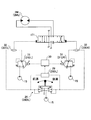
- FIG. 3 is a diagram illustrating a configuration example of a hydraulic system mounted on the excavator 100.
- FIG. 3 shows a mechanical power transmission system, a hydraulic oil line, a pilot line, and an electric control system by a double line, a solid line, a broken line, and a dotted line, respectively.
- the hydraulic system of the excavator 100 mainly includes an engine 11, a regulator 13, a main pump 14, a pilot pump 15, a control valve 17, an operating device 26, a discharge pressure sensor 28, an operating pressure sensor 29, a controller 30, and the like.
- the hydraulic system is configured to circulate the hydraulic oil from the main pump 14 driven by the engine 11 to the hydraulic oil tank via the center bypass pipeline 40 or the parallel pipeline 42.
- the engine 11 is a drive source of the excavator 100.
- the engine 11 is a diesel engine that operates so as to maintain a predetermined rotational speed.
- the output shaft of the engine 11 is connected to the input shafts of the main pump 14 and the pilot pump 15.
- the main pump 14 is configured to be able to supply hydraulic oil to the control valve 17 via the hydraulic oil line.
- the main pump 14 is a swash plate type variable displacement hydraulic pump.
- the regulator 13 is configured to control the discharge amount (push-out volume) of the main pump 14.
- the regulator 13 controls the discharge amount (push-out volume) of the main pump 14 by adjusting the swash plate tilt angle of the main pump 14 in accordance with a control command from the controller 30.
- the pilot pump 15 is configured to be able to supply hydraulic oil to a hydraulic control device including the operation device 26 via a pilot line.
- the pilot pump 15 is a fixed displacement hydraulic pump.
- the pilot pump 15 may be omitted.
- the function of the pilot pump 15 may be realized by the main pump 14. That is, the main pump 14 may have a function of supplying the operating oil to the operating device 26 after the pressure of the operating oil is reduced by a throttle or the like, in addition to the function of supplying the operating oil to the control valve 17. Good.
- the control valve 17 is a hydraulic control device that controls the hydraulic system in the excavator 100.
- the control valve 17 includes control valves 171 to 176.
- the control valve 175 includes a control valve 175L and a control valve 175R
- the control valve 176 includes a control valve 176L and a control valve 1756.
- the control valve 17 is configured to selectively supply hydraulic oil discharged from the main pump 14 to one or a plurality of hydraulic actuators through the control valves 171 to 176.
- the control valves 171 to 176 control, for example, the flow rate of hydraulic fluid that flows from the main pump 14 to the hydraulic actuator, and the flow rate of hydraulic fluid that flows from the hydraulic actuator to the hydraulic oil tank.
- the hydraulic actuator includes a boom cylinder 7, an arm cylinder 8, a bucket cylinder 9, a left traveling hydraulic motor 2ML, a right traveling hydraulic motor 2MR, and a turning hydraulic motor 2A.
- the operating device 26 is configured to be able to supply the hydraulic oil discharged from the pilot pump 15 to the pilot port of the corresponding control valve in the control valve 17 via the pilot line.
- the hydraulic oil pressure (pilot pressure) supplied to each pilot port is a pressure corresponding to the operation direction and operation amount of the operation device 26 corresponding to each hydraulic actuator.
- the operating device 26 may be an electric control type instead of the pilot pressure type as described above.
- the control valve in the control valve 17 may be an electromagnetic solenoid type spool valve.
- the discharge pressure sensor 28 is configured to detect the discharge pressure of the main pump 14. In the present embodiment, the discharge pressure sensor 28 outputs the detected value to the controller 30.
- the operation pressure sensor 29 is configured to detect the content of operation of the operation device 26 by the operator.
- the operation pressure sensor 29 detects the operation direction and operation amount of the operation device 26 corresponding to each of the actuators in the form of pressure (operation pressure), and outputs the detected value to the controller 30.
- the content of the operation of the operation device 26 may be detected using a sensor other than the operation pressure sensor.
- the main pump 14 includes a left main pump 14L and a right main pump 14R.
- the left main pump 14L circulates the hydraulic oil to the hydraulic oil tank via the left center bypass pipe 40L or the left parallel pipe 42L.
- the right main pump 14R circulates the hydraulic oil to the hydraulic oil tank via the right center bypass pipe 40R or the right parallel pipe 42R.
- the left center bypass conduit 40L is a hydraulic oil line that passes through control valves 171, 173, 175L, and 176L disposed in the control valve 17.
- the right center bypass pipeline 40R is a hydraulic oil line that passes through control valves 172, 174, 175R, and 176R disposed in the control valve 17.
- the control valve 171 supplies the hydraulic oil discharged from the left main pump 14L to the left traveling hydraulic motor 2ML, and discharges the hydraulic oil discharged from the left traveling hydraulic motor 2ML to the hydraulic oil tank.
- This is a spool valve for switching.
- the control valve 172 supplies the hydraulic oil discharged from the right main pump 14R to the right traveling hydraulic motor 2MR, and discharges the hydraulic oil discharged from the right traveling hydraulic motor 2MR to the hydraulic oil tank.
- This is a spool valve for switching.
- the control valve 173 is a spool that supplies the hydraulic oil discharged from the left main pump 14L to the swing hydraulic motor 2A and switches the flow of the hydraulic oil to discharge the hydraulic oil discharged from the swing hydraulic motor 2A to the hydraulic oil tank. It is a valve.
- the control valve 174 is a spool valve that supplies the hydraulic oil discharged from the right main pump 14R to the bucket cylinder 9 and switches the flow of the hydraulic oil in order to discharge the hydraulic oil in the bucket cylinder 9 to the hydraulic oil tank. .
- the control valve 175L is a spool valve that switches the flow of the hydraulic oil in order to supply the hydraulic oil discharged from the left main pump 14L to the boom cylinder 7.
- the control valve 175R is a spool valve that supplies the hydraulic oil discharged from the right main pump 14R to the boom cylinder 7 and switches the flow of the hydraulic oil in order to discharge the hydraulic oil in the boom cylinder 7 to the hydraulic oil tank. .
- the control valve 176L is a spool valve that supplies the hydraulic oil discharged from the left main pump 14L to the arm cylinder 8 and switches the flow of the hydraulic oil in order to discharge the hydraulic oil in the arm cylinder 8 to the hydraulic oil tank. .
- the control valve 176R is a spool valve that supplies the hydraulic oil discharged from the right main pump 14R to the arm cylinder 8 and switches the flow of the hydraulic oil in order to discharge the hydraulic oil in the arm cylinder 8 to the hydraulic oil tank. .
- the left parallel pipeline 42L is a hydraulic oil line parallel to the left center bypass pipeline 40L.
- the left parallel pipe 42L supplies hydraulic oil to the control valve downstream when the flow of hydraulic oil through the left center bypass pipe 40L is restricted or blocked by any of the control valves 171, 173, and 175L. it can.
- the right parallel pipeline 42R is a hydraulic oil line parallel to the right center bypass pipeline 40R.
- the right parallel pipe line 42R supplies hydraulic oil to the control valve downstream when the flow of the hydraulic oil passing through the right center bypass pipe line 40R is restricted or blocked by any of the control valves 172, 174, and 175R. it can.
- the regulator 13 includes a left regulator 13L and a right regulator 13R.
- the left regulator 13L controls the discharge amount of the left main pump 14L by adjusting the swash plate tilt angle of the left main pump 14L according to the discharge pressure of the left main pump 14L.
- the left regulator 13L for example, adjusts the swash plate tilt angle of the left main pump 14L according to an increase in the discharge pressure of the left main pump 14L, and decreases the discharge amount.
- the right regulator 13R This is because the absorption power (for example, absorption horsepower) of the main pump 14 represented by the product of the discharge pressure and the discharge amount does not exceed the output power (for example, output horsepower) of the engine 11.
- the operating device 26 includes a left operating lever 26L, a right operating lever 26R, and a traveling lever 26D.
- the travel lever 26D includes a left travel lever 26DL and a right travel lever 26DR.
- the left operation lever 26L is used for turning operation and arm 5 operation.
- the hydraulic oil discharged from the pilot pump 15 is used to introduce a control pressure corresponding to the lever operation amount into the pilot port of the control valve 176.
- the hydraulic oil discharged from the pilot pump 15 is used to introduce a control pressure corresponding to the lever operation amount into the pilot port of the control valve 173.
- the left operating lever 26L introduces hydraulic oil into the right pilot port of the control valve 176L and introduces hydraulic oil into the left pilot port of the control valve 176R when operated in the arm closing direction. . Further, when operated in the arm opening direction, the left operating lever 26L introduces hydraulic oil into the left pilot port of the control valve 176L and introduces hydraulic oil into the right pilot port of the control valve 176R. Further, the left operating lever 26L introduces hydraulic oil into the left pilot port of the control valve 173 when operated in the left turning direction, and the right pilot port of the control valve 173 when operated in the right turning direction. To introduce hydraulic oil.
- the right operation lever 26R is used for the operation of the boom 4 and the operation of the bucket 6.
- the hydraulic oil discharged from the pilot pump 15 is used to introduce a control pressure corresponding to the lever operation amount into the pilot port of the control valve 175.
- the hydraulic oil discharged from the pilot pump 15 is used to introduce a control pressure corresponding to the lever operation amount into the pilot port of the control valve 174.
- the right operation lever 26R introduces hydraulic oil into the right pilot port of the control valve 175R when operated in the boom lowering direction. Further, when operated in the boom raising direction, the right operating lever 26R introduces hydraulic oil into the right pilot port of the control valve 175L and introduces hydraulic oil into the left pilot port of the control valve 175R. Further, the right operation lever 26R introduces hydraulic oil into the left pilot port of the control valve 174 when operated in the bucket closing direction, and enters the right pilot port of the control valve 174 when operated in the bucket opening direction. Introduce hydraulic fluid.
- the traveling lever 26D is used for the operation of the crawler 1C.
- the left travel lever 26DL is used to operate the left crawler 1CL.
- the left travel lever 26DL may be configured to be interlocked with the left travel pedal.
- the hydraulic oil discharged from the pilot pump 15 is used to introduce a control pressure corresponding to the lever operation amount into the pilot port of the control valve 171.
- the right travel lever 26DR is used to operate the right crawler 1CR.
- the right travel lever 26DR may be configured to be interlocked with the right travel pedal.
- the hydraulic oil discharged from the pilot pump 15 is used to introduce a control pressure corresponding to the lever operation amount into the pilot port of the control valve 172.
- the discharge pressure sensor 28 includes a discharge pressure sensor 28L and a discharge pressure sensor 28R.
- the discharge pressure sensor 28L detects the discharge pressure of the left main pump 14L and outputs the detected value to the controller 30. The same applies to the discharge pressure sensor 28R.
- the operation pressure sensor 29 includes operation pressure sensors 29LA, 29LB, 29RA, 29RB, 29DL, and 29DR.
- the operation pressure sensor 29LA detects the content of the operation of the left operation lever 26L by the operator in the front-rear direction in the form of pressure, and outputs the detected value to the controller 30.
- the contents of the operation include, for example, a lever operation direction and a lever operation amount (lever operation angle).
- the operation pressure sensor 29LB detects the content of the operation of the left operation lever 26L by the operator in the left-right direction in the form of pressure, and outputs the detected value to the controller 30.
- the operation pressure sensor 29RA detects the content of the operation of the right operation lever 26R by the operator in the front-rear direction in the form of pressure, and outputs the detected value to the controller 30.
- the operation pressure sensor 29RB detects the content of the operation of the right operation lever 26R by the operator in the left-right direction in the form of pressure, and outputs the detected value to the controller 30.
- the operation pressure sensor 29DL detects the content of the operation of the left travel lever 26DL by the operator in the front-rear direction in the form of pressure, and outputs the detected value to the controller 30.
- the operation pressure sensor 29DR detects the content of the operation in the front-rear direction on the right travel lever 26DR by the operator in the form of pressure, and outputs the detected value to the controller 30.
- the controller 30 receives the output of the operation pressure sensor 29, outputs a control command to the regulator 13 as necessary, and changes the discharge amount of the main pump 14. Further, the controller 30 receives the output of the control pressure sensor 19 provided upstream of the throttle 18, outputs a control command to the regulator 13 as necessary, and changes the discharge amount of the main pump 14.
- the diaphragm 18 includes a left diaphragm 18L and a right diaphragm 18R, and the control pressure sensor 19 includes a left control pressure sensor 19L and a right control pressure sensor 19R.
- a left throttle 18L is disposed between the control valve 176L located at the most downstream side and the hydraulic oil tank. Therefore, the flow of hydraulic oil discharged from the left main pump 14L is limited by the left throttle 18L.
- the left diaphragm 18L generates a control pressure for controlling the left regulator 13L.
- the left control pressure sensor 19L is a sensor for detecting this control pressure, and outputs the detected value to the controller 30.
- the controller 30 controls the discharge amount of the left main pump 14L by adjusting the swash plate tilt angle of the left main pump 14L according to the control pressure. For example, the controller 30 decreases the discharge amount of the left main pump 14L as the control pressure increases, and increases the discharge amount of the left main pump 14L as the control pressure decreases.
- the discharge amount of the right main pump 14R is similarly controlled.
- the hydraulic oil discharged from the left main pump 14L passes through the left center bypass conduit 40L to the left.
- the diaphragm reaches 18L.
- the flow of hydraulic oil discharged from the left main pump 14L increases the control pressure generated upstream of the left throttle 18L.
- the controller 30 reduces the discharge amount of the left main pump 14L to the allowable minimum discharge amount, and suppresses the pressure loss (pumping loss) when the discharged hydraulic oil passes through the left center bypass conduit 40L.
- the hydraulic oil discharged from the left main pump 14L flows into the operation target hydraulic actuator via the control valve corresponding to the operation target hydraulic actuator.
- the flow of the hydraulic oil discharged from the left main pump 14L reduces or disappears the amount reaching the left throttle 18L, and lowers the control pressure generated upstream of the left throttle 18L.
- the controller 30 increases the discharge amount of the left main pump 14L, causes sufficient hydraulic oil to flow into the operation target hydraulic actuator, and ensures the operation of the operation target hydraulic actuator.
- the controller 30 similarly controls the discharge amount of the right main pump 14R.
- the hydraulic system of FIG. 3 can suppress wasteful energy consumption in the main pump 14 in the standby state.
- the wasteful energy consumption includes a pumping loss generated by the hydraulic oil discharged from the main pump 14 in the center bypass conduit 40. 3 can reliably supply necessary and sufficient hydraulic fluid from the main pump 14 to the hydraulic actuator to be operated when the hydraulic actuator is operated.
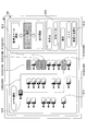
- FIGS. 4A-4D are diagrams of a portion of the hydraulic system.
- FIG. 4A is a partial view of the hydraulic system related to the operation of the arm cylinder 8
- FIG. 4B is a partial view of the hydraulic system related to the operation of the swing hydraulic motor 2A
- 4C is a diagram of a part of the hydraulic system related to the operation of the boom cylinder 7
- FIG. 4D is a diagram of a part of the hydraulic system related to the operation of the bucket cylinder 9.
- FIGS. 5A and 5B are diagrams of a portion of a hydraulic system.
- FIG. 5A is a diagram of a part of the hydraulic system related to the operation of the left travel hydraulic motor 2ML
- FIG. 5B is a diagram of a part of the hydraulic system related to the operation of the right travel hydraulic motor 2MR.
- the hydraulic system includes a proportional valve 31 and a shuttle valve 32.
- the proportional valve 31 includes proportional valves 31AL to 31FL and 31AR to 31FR
- the shuttle valve 32 includes shuttle valves 32AL to 32FL and 32AR to 32FR.
- the proportional valve 31 is configured to function as a control valve for machine control.
- the proportional valve 31 is arranged in a pipe line connecting the pilot pump 15 and the shuttle valve 32, and is configured so that the flow path area of the pipe line can be changed.
- the proportional valve 31 operates according to a control command output from the controller 30. Therefore, the controller 30 controls the pilot oil of the corresponding control valve in the control valve 17 through the proportional valve 31 and the shuttle valve 32 via the proportional valve 31 and the shuttle valve 32, regardless of the operation of the operating device 26 by the operator. Can be supplied to the port.
- the shuttle valve 32 has two inlet ports and one outlet port. One of the two inlet ports is connected to the operating device 26, and the other is connected to the proportional valve 31. The outlet port is connected to the pilot port of the corresponding control valve in the control valve 17. Therefore, the shuttle valve 32 can cause the higher one of the pilot pressure generated by the operating device 26 and the pilot pressure generated by the proportional valve 31 to act on the pilot port of the corresponding control valve.
- the controller 30 can operate the hydraulic actuator corresponding to the specific operation device 26 even when the operation to the specific operation device 26 is not performed.
- the left operation lever 26L is used to operate the arm 5.
- the left operation lever 26L uses the hydraulic oil discharged from the pilot pump 15 to apply a pilot pressure corresponding to the operation in the front-rear direction to the pilot port of the control valve 176.
- the pilot pressure corresponding to the operation amount is applied to the right pilot port of the control valve 176L and the left pilot port of the control valve 176R.
- the pilot pressure corresponding to the operation amount is applied to the left pilot port of the control valve 176L and the right pilot port of the control valve 176R.
- the left operation lever 26L is provided with a switch NS.
- the switch NS is a push button switch. The operator can manually operate the left operation lever 26L while pressing the switch NS with a finger.
- the switch NS may be provided on the right operation lever 26 ⁇ / b> R, or may be provided at another position in the cabin 10.
- the operation pressure sensor 29LA detects the content of the operation of the left operation lever 26L by the operator in the front-rear direction in the form of pressure, and outputs the detected value to the controller 30.
- the proportional valve 31AL operates according to the current command output from the controller 30.
- the proportional valve 31AL adjusts the pilot pressure by the hydraulic oil introduced from the pilot pump 15 to the right pilot port of the control valve 176L and the left pilot port of the control valve 176R via the proportional valve 31AL and the shuttle valve 32AL.
- the proportional valve 31AR operates in accordance with a current command output from the controller 30.
- the proportional valve 31AR adjusts the pilot pressure by the hydraulic oil introduced from the pilot pump 15 to the left pilot port of the control valve 176L and the right pilot port of the control valve 176R via the proportional valve 31AR and the shuttle valve 32AR.
- Each of the proportional valves 31AL and 31AR can adjust the pilot pressure so that the control valve 176 can be stopped at an arbitrary valve position.
- the controller 30 allows the hydraulic oil discharged from the pilot pump 15 to flow through the proportional valve 31AL and the shuttle valve 32AL, regardless of the arm closing operation by the operator, and to the right pilot port and the control valve 176R of the control valve 176L. Can be supplied to the left pilot port. That is, the controller 30 can close the arm 5 regardless of the arm closing operation by the operator. Further, the controller 30 supplies the hydraulic oil discharged from the pilot pump 15 to the left pilot port of the control valve 176L and the right side of the control valve 176R via the proportional valve 31AR and the shuttle valve 32AR regardless of the arm opening operation by the operator. Can be supplied to the pilot port. That is, the controller 30 can open the arm 5 regardless of the arm opening operation by the operator.
- the left operation lever 26L is also used to operate the turning mechanism 2. Specifically, the left operation lever 26L uses the hydraulic oil discharged from the pilot pump 15 to apply a pilot pressure corresponding to the operation in the left-right direction to the pilot port of the control valve 173. More specifically, the left operation lever 26L causes a pilot pressure corresponding to the operation amount to act on the left pilot port of the control valve 173 when operated in the left turning direction (left direction). Further, when the left operation lever 26L is operated in the right turning direction (right direction), the pilot pressure corresponding to the operation amount is applied to the right pilot port of the control valve 173.
- the operation pressure sensor 29LB detects the content of the operation of the left operation lever 26L by the operator in the left-right direction in the form of pressure, and outputs the detected value to the controller 30.
- the proportional valve 31BL operates according to a current command output from the controller 30.
- the proportional valve 31BL adjusts the pilot pressure by the hydraulic oil introduced from the pilot pump 15 to the left pilot port of the control valve 173 via the proportional valve 31BL and the shuttle valve 32BL.
- the proportional valve 31BR operates in accordance with a current command output from the controller 30.
- the proportional valve 31BR adjusts the pilot pressure by the hydraulic oil introduced from the pilot pump 15 to the right pilot port of the control valve 173 via the proportional valve 31BR and the shuttle valve 32BR.
- Each of the proportional valves 31BL and 31BR can adjust the pilot pressure so that the control valve 173 can be stopped at an arbitrary valve position.
- the controller 30 can supply the hydraulic oil discharged from the pilot pump 15 to the left pilot port of the control valve 173 via the proportional valve 31BL and the shuttle valve 32BL regardless of the left turning operation by the operator. That is, the controller 30 can turn the turning mechanism 2 to the left regardless of the left turning operation by the operator. Further, the controller 30 can supply the hydraulic oil discharged from the pilot pump 15 to the right pilot port of the control valve 173 via the proportional valve 31BR and the shuttle valve 32BR regardless of the right turning operation by the operator. That is, the controller 30 can turn the turning mechanism 2 to the right regardless of the right turning operation by the operator.
- the right operation lever 26R is used to operate the boom 4. Specifically, the right operation lever 26R uses the hydraulic oil discharged from the pilot pump 15 to apply a pilot pressure corresponding to the operation in the front-rear direction to the pilot port of the control valve 175. More specifically, when the right operation lever 26R is operated in the boom raising direction (rearward direction), the pilot pressure corresponding to the operation amount is applied to the right pilot port of the control valve 175L and the left pilot port of the control valve 175R. Make it work. Further, when the right operation lever 26R is operated in the boom lowering direction (forward direction), the pilot pressure corresponding to the operation amount is applied to the right pilot port of the control valve 175R.
- the operation pressure sensor 29RA detects the content of the operation of the right operation lever 26R by the operator in the front-rear direction in the form of pressure, and outputs the detected value to the controller 30.
- the proportional valve 31CL operates in accordance with a current command output from the controller 30.
- the proportional valve 31CL adjusts the pilot pressure by the hydraulic oil introduced from the pilot pump 15 to the right pilot port of the control valve 175L and the left pilot port of the control valve 175R via the proportional valve 31CL and the shuttle valve 32CL.
- the proportional valve 31CR operates in accordance with a current command output from the controller 30.
- the proportional valve 31CR adjusts the pilot pressure by the hydraulic oil introduced from the pilot pump 15 to the left pilot port of the control valve 175L and the right pilot port of the control valve 175R via the proportional valve 31CR and the shuttle valve 32CR.
- Each of the proportional valves 31CL and 31CR can adjust the pilot pressure so that the control valve 175 can be stopped at an arbitrary valve position.
- the controller 30 allows the hydraulic oil discharged from the pilot pump 15 to flow through the proportional valve 31CL and the shuttle valve 32CL, regardless of the boom raising operation by the operator, and the right pilot port and the control valve 175R of the control valve 175L. Can be supplied to the left pilot port. That is, the controller 30 can raise the boom 4 regardless of the boom raising operation by the operator. Further, the controller 30 can supply the hydraulic oil discharged from the pilot pump 15 to the right pilot port of the control valve 175R via the proportional valve 31CR and the shuttle valve 32CR regardless of the boom lowering operation by the operator. That is, the controller 30 can lower the boom 4 regardless of the boom lowering operation by the operator.
- the right operation lever 26R is also used to operate the bucket 6. Specifically, the right operation lever 26R uses the hydraulic oil discharged from the pilot pump 15 to apply a pilot pressure corresponding to the operation in the left-right direction to the pilot port of the control valve 174. More specifically, the right operation lever 26R applies a pilot pressure corresponding to the operation amount to the left pilot port of the control valve 174 when operated in the bucket closing direction (left direction). Further, when the right operation lever 26R is operated in the bucket opening direction (right direction), the pilot pressure corresponding to the operation amount is applied to the right pilot port of the control valve 174.
- the operation pressure sensor 29RB detects the content of the operation of the right operation lever 26R by the operator in the left-right direction in the form of pressure, and outputs the detected value to the controller 30.
- the proportional valve 31DL operates in accordance with a current command output from the controller 30.
- the proportional valve 31DL adjusts the pilot pressure by the hydraulic oil introduced from the pilot pump 15 to the left pilot port of the control valve 174 via the proportional valve 31DL and the shuttle valve 32DL.
- the proportional valve 31DR operates in accordance with a current command output from the controller 30.
- the proportional valve 31DR adjusts the pilot pressure by the hydraulic oil introduced from the pilot pump 15 to the right pilot port of the control valve 174 via the proportional valve 31DR and the shuttle valve 32DR.
- Each of the proportional valves 31DL and 31DR can adjust the pilot pressure so that the control valve 174 can be stopped at an arbitrary valve position.
- the controller 30 can supply the hydraulic oil discharged from the pilot pump 15 to the left pilot port of the control valve 174 via the proportional valve 31DL and the shuttle valve 32DL regardless of the bucket closing operation by the operator. That is, the controller 30 can close the bucket 6 regardless of the bucket closing operation by the operator. Further, the controller 30 can supply the hydraulic oil discharged from the pilot pump 15 to the right pilot port of the control valve 174 via the proportional valve 31DR and the shuttle valve 32DR regardless of the bucket opening operation by the operator. That is, the controller 30 can open the bucket 6 regardless of the bucket opening operation by the operator.
- the left travel lever 26DL is used to operate the left crawler 1CL. Specifically, the left travel lever 26DL uses the hydraulic oil discharged from the pilot pump 15 to apply a pilot pressure corresponding to the operation in the front-rear direction to the pilot port of the control valve 171. More specifically, the left travel lever 26DL applies a pilot pressure corresponding to the operation amount to the left pilot port of the control valve 171 when operated in the forward direction (forward direction). Further, when the left travel lever 26DL is operated in the reverse direction (rearward direction), the pilot pressure corresponding to the operation amount is applied to the right pilot port of the control valve 171.
- the operation pressure sensor 29DL detects the content of the operation of the left traveling lever 26DL by the operator in the front-rear direction in the form of pressure, and outputs the detected value to the controller 30.
- the proportional valve 31EL operates according to the current command output from the controller 30.
- the proportional valve 31EL adjusts the pilot pressure by the hydraulic oil introduced from the pilot pump 15 to the left pilot port of the control valve 171 via the proportional valve 31EL and the shuttle valve 32EL.
- the proportional valve 31ER operates in accordance with a current command output from the controller 30.
- the proportional valve 31ER adjusts the pilot pressure by the hydraulic oil introduced from the pilot pump 15 to the right pilot port of the control valve 171 via the proportional valve 31ER and the shuttle valve 32ER.
- Each of the proportional valves 31EL and 31ER can adjust the pilot pressure so that the control valve 171 can be stopped at an arbitrary valve position.
- the controller 30 can supply the hydraulic oil discharged from the pilot pump 15 to the left pilot port of the control valve 171 via the proportional valve 31EL and the shuttle valve 32EL, regardless of the left forward operation by the operator. That is, the controller 30 can move the left crawler 1CL forward regardless of the left forward operation by the operator. Further, the controller 30 can supply the hydraulic oil discharged from the pilot pump 15 to the right pilot port of the control valve 171 via the proportional valve 31ER and the shuttle valve 32ER, regardless of the left reverse operation by the operator. That is, the controller 30 can reverse the left crawler 1CL regardless of the left reverse operation by the operator.
- the right travel lever 26DR is used to operate the right crawler 1CR. Specifically, the right travel lever 26DR uses the hydraulic oil discharged from the pilot pump 15 to apply a pilot pressure corresponding to the operation in the front-rear direction to the pilot port of the control valve 172. More specifically, when the right travel lever 26DR is operated in the forward direction (forward direction), the pilot pressure corresponding to the operation amount is applied to the right pilot port of the control valve 172. Further, when the right travel lever 26DR is operated in the reverse direction (rearward direction), the pilot pressure corresponding to the operation amount is applied to the left pilot port of the control valve 172.
- the operation pressure sensor 29DR detects the content of the operation of the right travel lever 26DR by the operator in the front-rear direction in the form of pressure, and outputs the detected value to the controller 30.
- the proportional valve 31FL operates according to a current command output from the controller 30.
- the proportional valve 31FL adjusts the pilot pressure by the hydraulic oil introduced from the pilot pump 15 to the left pilot port of the control valve 172 via the proportional valve 31FL and the shuttle valve 32FL.
- the proportional valve 31FR operates in accordance with a current command output from the controller 30.
- the proportional valve 31FR adjusts the pilot pressure by the hydraulic oil introduced from the pilot pump 15 to the right pilot port of the control valve 172 via the proportional valve 31FR and the shuttle valve 32FR.
- Each of the proportional valves 31FL and 31FR can adjust the pilot pressure so that the control valve 172 can be stopped at an arbitrary valve position.
- the controller 30 can supply the hydraulic oil discharged from the pilot pump 15 to the right pilot port of the control valve 172 via the proportional valve 31FL and the shuttle valve 32FL regardless of the right forward operation by the operator. That is, the controller 30 can move the right crawler 1CR forward irrespective of the right forward operation by the operator. Further, the controller 30 can supply the hydraulic oil discharged from the pilot pump 15 to the left pilot port of the control valve 172 via the proportional valve 31FR and the shuttle valve 32FR regardless of the right reverse operation by the operator. That is, the controller 30 can move the right crawler 1CR backward irrespective of the right reverse operation by the operator.
- a hydraulic operation lever having a hydraulic pilot circuit is employed, but an electric pilot circuit is provided instead of a hydraulic operation lever having such a hydraulic pilot circuit.
- An electric operation lever may be employed.
- the lever operation amount of the electric operation lever is input to the controller 30 as an electric signal.
- An electromagnetic valve is disposed between the pilot pump 15 and the pilot port of each control valve.
- the solenoid valve is configured to operate in response to an electrical signal from the controller 30.
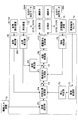
- FIG. 6 is a functional block diagram illustrating a configuration example of the controller 30.
- the controller 30 receives a signal output from at least one of the posture detection device, the operation device 26, the space recognition device 70, the orientation detection device 71, the information input device 72, the positioning device 73, the switch NS, and the like.
- Various operations are executed, and a control command can be output to at least one of the proportional valve 31, the display device D1, the sound output device D2, and the like.
- the attitude detection device includes a boom angle sensor S1, an arm angle sensor S2, a bucket angle sensor S3, a body tilt sensor S4, and a turning angular velocity sensor S5.
- the controller 30 includes a posture detection unit 30A, a determination unit 30B, and an autonomous control unit 30C as functional elements that perform various functions. Each functional element may be configured by hardware or may be configured by software.
- the posture detection unit 30A is configured to detect information related to the posture of the excavator 100.
- the posture detection unit 30A detects information related to the posture of the excavator 100 based on the output of the posture detection device.
- the posture detection unit 30A may detect the posture of the excavation attachment AT as the posture of the excavator 100 based on the output of the posture detection device.
- the posture detection unit 30A determines the posture of the upper swing body 3 (the direction of the upper swing body 3 relative to the direction of the lower traveling body 1) as the position of the excavator 100 based on at least one output of the posture detection device and the direction detection device. It may be detected.
- the determination unit 30B is configured to be able to determine whether a desired space exists.
- the determination unit 30B is configured to be able to determine the presence or absence of a parking space that is a space in which the excavator 100 can be parked and the presence or absence of a passage space that is a space through which the excavator 100 can pass. ing.
- the determination unit 30B determines whether there is a space larger than the body of the excavator 100 in the designated space designated as the parking space, or on the path from the current position to the designated space designated as the parking space.
- the determination unit 30 ⁇ / b> B determines whether there is a parking space based on the output of the space recognition device 70. In addition, when the determination unit 30B determines that a parking space exists, the determination unit 30B determines whether there is a passing space for moving the excavator 100 from the current position to the parking space without bringing the excavator 100 into contact with an external object. judge. When it is determined that there is a passing space, the determination unit 30B determines that the excavator 100 can be moved and parked in the parking space.
- the autonomous control unit 30C is configured to operate the excavator 100 autonomously.
- the autonomous control unit 30C is configured to calculate a target trajectory from the current position of the excavator 100 to the parking space, and to move the excavator 100 along the target trajectory.
- the target trajectory is a trajectory drawn by a predetermined portion of the excavator 100 when the excavator 100 moves autonomously.
- the target trajectory includes, for example, a target trajectory related to the crawler 1C.
- the predetermined part is, for example, the front end or the rear end of the crawler 1C.
- the target trajectory may include, for example, a target trajectory related to the excavation attachment AT.
- the predetermined part is, for example, the tip of the boom 4.
- the target trajectory may be a trajectory drawn by the center point of the excavator 100 as a predetermined part.
- the center point of the shovel 100 is typically a point on the pivot axis.
- the target trajectory may be a trajectory having a width drawn by the outline of the excavator 100 moving from the current position to the parking space.
- the target trajectory is calculated, for example, to move the excavator 100 to a specific parking space and park it.
- the target trajectory is calculated in consideration of the movement that the excavator 100 can realize.
- the autonomous control unit 30C determines how to move the actuator based on the calculated target trajectory. For example, when the excavator 100 is moved backward, the autonomous control unit 30C selects an appropriate movement method from spin turn, pivot turn, slow turn, or straight travel and determines how to move the traveling hydraulic motor 2M. At that time, the autonomous control unit 30C may not only determine whether the travel drive unit such as the travel hydraulic motor 2M needs to operate, but may also determine whether the turning mechanism 2 needs to be operated. In addition, the autonomous control unit 30C may determine whether or not the attachment may come into contact with peripheral equipment or other construction machines, and determine whether or not the operation of the attachment is necessary.
- FIG. 7 is a flowchart of an example of the parking process.
- the controller 30 determines whether or not the parking mode button has been pressed (step ST1). In the present embodiment, the controller 30 repeatedly performs this determination every predetermined control cycle.
- the parking mode button is, for example, a switch NS provided at the tip of the left operation lever 26L.
- the parking mode button may be a software button displayed on the display device D1 having a touch panel. The controller 30 repeats this determination until it determines that the parking mode button has been pressed (NO in step ST1).
- step ST2 When it is determined that the parking mode button has been pressed (YES in step ST1), the controller 30 displays a setting screen (step ST2). In the present embodiment, the controller 30 causes the display device D1 to display a parking space selection screen as a setting screen.
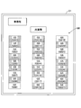
- FIG. 8 shows a configuration example of the parking space selection screen.
- the parking space selection screen GA includes an excavator graphic G1 and a parking space graphic G2.
- the parking space selection screen GA shown in FIG. 8 may be displayed on a display device mounted on a support device including a mobile terminal such as a smartphone that the operator has.
- the support device functions as a communication device, and is connected via Wi-Fi (registered trademark), Bluetooth (registered trademark), or a short-range wireless communication network such as a wireless LAN, a cellular phone communication network, or a satellite communication network. You may control communication with the excavator.
- Wi-Fi registered trademark
- Bluetooth registered trademark
- a short-range wireless communication network such as a wireless LAN, a cellular phone communication network, or a satellite communication network. You may control communication with the excavator.
- the excavator graphic G1 and the parking space graphic G2 indicate the positional relationship between the upper swing body 3 and the parking space.
- the excavator figure G1 represents the shape of the upper swing body 3 when the upper swing body 3 is viewed from directly above.
- the parking space figure G2 represents a rough position with respect to the upper swing body 3 of a space that can be set as a parking space.
- the parking space graphic G2 includes a right parking space graphic G2R that represents a space on the right side of the upper swing body 3, a front parking space graphic G2F that represents a space on the front side of the upper swing body 3, and A left parking space graphic G2L representing a space on the left side and a rear parking space graphic G2B representing a space on the rear side of the upper swing body 3 are included.
- the parking space graphic G2 includes five or more parking spaces including at least one of a right diagonal front parking space graphic, a left diagonal front parking space graphic, a right diagonal rear parking space graphic, and a left diagonal rear parking space graphic. Space figures may be included.
- the parking space figure G2 may represent a more exact position with respect to the upper swing body 3 of a space that can be set as a parking space.
- the parking space graphic G2 may correspond only to the parking space recognized by the space recognition device 70. In this case, for example, when the controller 30 determines that there is no parking space on the left side of the upper swing body 3, the controller 30 may not display the left parking space graphic G2L.
- the parking space figure G2 may be superimposed on the camera image.
- the camera image is, for example, a bird's-eye view image as a viewpoint conversion image generated based on images acquired by a plurality of cameras attached to the upper swing body 3.
- the bird's-eye view image is displayed around the excavator figure G1.
- the parking space selection screen GA may be a screen related to a scene when the back is viewed from the excavator 100 instead of a screen related to the scene when the excavator 100 is viewed from directly above as described above. It may be a screen related to a sight when the side is viewed.
- the operator of the excavator 100 selects the parking space figure G2 including the space where the excavator 100 is to be parked while looking at the parking space selection screen GA.
- the controller 30 determines whether or not a target parking space has been set (step ST3).
- the operator of the excavator 100 presses the parking mode button in the cabin 10 of the excavator 100 at a position as shown in FIG.
- FIG. 9 is a top view of an actual parking lot at a construction site or a garage (parking lot).
- the controller 30 displays a parking space selection screen GA.
- the operator can set the space SP in the actual parking lot as the target parking space by selecting the right parking space graphic G2R.
- the determination unit 30B of the controller 30 determines that the space where the excavator 100 can be parked is based on the output of the space recognition device 70. It is determined whether or not it exists. In the example of FIG. 9, there is a wall W on the left side of the upper swing body 3, and there is no space in which the excavator 100 can be parked. In this case, the determination unit 30B may determine that there is no space where the excavator 100 can be parked on the left side of the upper swing body 3, and may display a text message indicating that on the parking space selection screen GA. .
- the determination unit 30B determines whether or not a space in which the excavator 100 can be parked exists on the right side of the upper swing body 3 based on the output of the space recognition device 70. Determine.
- the space SP designated as the parking space is a larger space than the excavator 100 body. That is, a space SP where the excavator 100 can be parked exists on the right side of the upper swing body 3.
- the controller 30 recognizes the designated space SP as the end point of the target trajectory. Therefore, the controller 30 can interrupt and stop the travel of the excavator 100 in the designated space SP even if another space exists farther than the designated space SP.
- the determination unit 30B determines that there is a space SP in which the excavator 100 can be parked on the right side of the upper swing body 3.
- the determination unit 30B determines whether there is a passing space for moving the excavator 100 from the current position to the space SP.
- the determination unit 30B determines whether or not there is continuously a space (a space through which the aircraft can pass) larger than the body of the excavator 100 on the path from the current position to the space SP designated as the parking space. To do.
- the determination unit 30B determines that the excavator 100 cannot be moved to the space SP, and accordingly. May be displayed on the parking space selection screen GA. When it determines with a passage space being securable, the determination part 30B sets space SP as a target parking space.
- step ST3 If it is determined that the target parking space is not set (NO in step ST3), the controller 30 repeats the determination in step ST3 until the target parking space is set.
- the controller 30 adjusts the posture of the attachment (step ST4).
- the autonomous control unit 30C of the controller 30 changes the posture of the excavation attachment AT to a posture suitable for traveling (hereinafter referred to as “traveling posture”).
- the traveling posture is a posture registered in advance, for example, a posture that maximizes the boom angle ⁇ 1 and minimizes the arm angle ⁇ 2 and the bucket angle ⁇ 3.
- the autonomous control unit 30C changes the posture of the excavation attachment AT to the traveling posture when it is determined that the posture of the excavation attachment AT detected by the posture detection unit 30A is not the traveling posture.
- the controller 30 is basically configured on the assumption that the operator of the excavator 100 does not operate the operating device 26 while the processes after step ST4 are being executed. Therefore, the excavator 100 may be configured such that the operation on the operation device 26 by the operator is invalid, except for an operation for forcibly ending the parking process.
- the operation for forcibly ending the parking process is, for example, a re-operation of the parking mode button. Further, the operator of the excavator 100 may perform operations related to the processing up to step ST3 outside the cabin 10.
- the operator of the excavator 100 can monitor the movement of the excavator 100 from the outside of the cabin 10 while the processing after step ST4 is being executed, and can perform a parking process as needed by an operation from a portable terminal or the like. It can be forcibly terminated.
- the autonomous control unit 30C determines a target trajectory (step ST5).
- the autonomous control unit 30C determines the trajectory drawn by the rear end of the crawler 1C when the excavator 100 moves from the current position to the space SP. Further, the autonomous control unit 30C determines the space SP as the end point of the target trajectory.
- the order of the operations of the crawler 1C based on the necessity of the turn is also determined.
- the order of operations of the crawler 1C may include, for example, the order of operations of the left traveling hydraulic motor 2ML and the right traveling hydraulic motor 2MR.
- the autonomous control unit 30C moves the excavator 100 along the determined target trajectory (step ST6).
- the autonomous control unit 30C first executes a spin turn of about 45 degrees counterclockwise, and directs the rear end of the crawler 1C toward the space SP.
- the autonomous control unit 30C rotates the right traveling hydraulic motor 2MR in the forward direction and rotates the left traveling hydraulic motor 2ML in the reverse direction to execute a counterclockwise spin turn.
- the autonomous control unit 30C performs a gentle turn and moves the excavator 100 back along a target track that gently curves counterclockwise, while the other traveling shovel parked around the lower traveling body 1
- the autonomous control unit 30C causes the left traveling hydraulic motor 2ML to reversely rotate at a rotational speed faster than the reverse rotation of the right traveling hydraulic motor 2MR to execute a counterclockwise gentle turn.
- the autonomous control unit 30C causes the vehicle to move straight forward and backward, and causes the entire shovel 100 to enter the space SP.
- the autonomous control unit 30C reversely rotates the right traveling hydraulic motor 2MR and the left traveling hydraulic motor 2ML at the same rotational speed to retract the shovel 100 straight.
- the autonomous control unit 30C may change the posture of the excavation attachment AT as necessary when moving the crawler 1C. For example, when the excavator 100 is moved backward, the boom 4 may be lowered when it is determined that there is a possibility that the excavation attachment AT may come into contact with the electric wire stretched at a position higher than the cabin 10. In this case, the autonomous control unit 30C may recognize the presence of an obstacle such as an electric wire based on the output of the space recognition device 70, for example. Then, the autonomous control unit 30C may return the posture of the excavation attachment AT to the traveling posture by raising the boom 4 after passing through the electric wire.
- the autonomous control unit 30C may turn the upper turning body 3 as necessary when moving the crawler 1C.
- the excavation attachment AT may come into contact with the wall W when the autonomous control unit 30C performs a spin turn of 45 degrees or more counterclockwise without turning the upper swing body 3.
- the autonomous control unit 30C may prevent the excavation attachment AT from contacting the wall W by turning the upper turning body 3 clockwise before or during the execution of the spin turn.
- the autonomous control unit 30C may recognize the presence of an obstacle such as the wall W based on the output of the space recognition device 70, for example.
- the autonomous control unit 30C grounds the attachment in the target parking space (step ST7).
- the autonomous control unit 30 ⁇ / b> C stops the movement of the crawler 1 ⁇ / b> C after the entire excavator 100 has entered the space SP, and the posture of the excavation attachment AT is set to a posture suitable for parking (hereinafter, “parking posture”). ")".
- the parking posture is a posture registered in advance, for example, a posture in which the bucket 6 is in contact with the ground.
- the parking posture may be the same as the traveling posture, or may be another posture where the excavation attachment AT does not contact the ground.
- the parking posture may be configured to be selected from a plurality of postures. The same applies to the running posture.
- the autonomous control unit 30C notifies the completion of parking (step ST8).
- the autonomous control unit 30C causes the display device D1 to display information notifying that parking has been completed when the posture of the excavation attachment AT is changed to the parking posture, and notifies that parking has been completed. Information is output from the sound output device D2.
- the parking space selection screen GB includes a map figure including information related to the arrangement of other construction machines, a delivery area, and an office in the parking lot, and a parking space figure GS.
- the unloading place is a place for loading the excavator 100 on a transport vehicle such as a trailer or unloading the excavator 100 from the transport vehicle.
- the parking space figure GS indicates the position of the parking space that can be selected as a parking space that is a space for parking the excavator 100.
- the parking space graphic GS includes 27 parking space graphics GS1 to GS27.
- the parking space graphic GS shown in FIG. 10 corresponds to the parking lot shown in FIG. FIG. 11 is a top view of an actual parking lot.
- the parking lot of FIG. 11 is a parking lot owned by a construction machine rental company, for example, and includes three parking space rows in which nine excavators can be parked in a row. At the present time, 18 excavators are parked in the parking lot of FIG. 11 in addition to the excavator 100 just dropped from the trailer.
- the position information regarding each parking space is registered in advance.
- the position information regarding each parking space includes, for example, the latitude, longitude, and altitude of the center point of each parking space.
- the controller 30 includes a parking space graphic GS related to a parking space already parked by another construction machine such as an excavator, a bulldozer, a wheel loader, a crane, or a road roller, among the parking space graphic GS.
- the parking space figure GS related to the parking space where no other construction machine is parked may be displayed so that the operator can distinguish it.
- the dot hatching is attached
- the parking space figure GS regarding the parking space where other construction machines are not parked is not dot-hatched.
- each construction machine such as an excavator or a wheel loader is equipped with a device capable of specifying position information such as a GNSS receiver. Then, the position information of each construction machine is transmitted from each construction machine to a management device arranged in the office or the like via a communication network such as a short-range wireless communication network, a mobile phone communication network, or a satellite communication network. .
- the management apparatus can grasp
- the management apparatus can transmit arrangement information to the excavator 100 scheduled to park in the future. Thereby, the operator of the shovel 100 can check the parking space selection screen GB shown in FIG.
- the parking space selection screen GB shown in FIG. 10 may be displayed on the display device D1 of the management device.
- the parking space selection screen G shown in FIG. 10 may be displayed on the display device D1 of a support device including a mobile terminal such as a smartphone that the operator has.
- the operator of the excavator 100 touches the parking space figure GS corresponding to the parking space where the excavator 100 is to be parked while looking at the parking space selection screen GB inside the cabin 10 or outside the cabin 10. Select by operation.
- the controller 30 may display a parking space selection screen GB so that the operator can distinguish between the parking space graphic GS selected by the operator and other parking space graphics GS. .
- the parking space figure GS26 selected by the operator is hatched.
- the operator of the excavator 100 can set the space SP in the actual parking lot as shown in FIG. 11 as the target parking space by selecting the parking space graphic GS26.
- the autonomous control unit 30C of the controller 30 creates a track from the current position to the designated space based on the arrangement information, and the left traveling hydraulic motor 2ML and the right traveling hydraulic motor 2MR Operate at least one. Then, the autonomous control unit 30C compares at least one of the left traveling hydraulic motor 2ML and the right traveling hydraulic motor 2MR while comparing the output of the positioning device 73 with the created trajectory, and moves the excavator 100 near the target parking space. To move. In the example of FIG. 11, the excavator 100 is moved along the movement route TR indicated by a broken line. The creation of the trajectory from the current position to the designated space based on the arrangement information may be executed by the management device. When the excavator 100 moves, the autonomous control unit 30C may change the posture of the excavation attachment AT as necessary so that the excavator 100 does not contact other objects as described above. You may make it turn.
- FIG. 12 shows a parking space selection screen GC which is still another configuration example of the parking space selection screen.
- the parking space selection screen GC shown in FIG. 12 includes graphics G10 to G15.
- the figure G10 represents the excavator 100 that the operator intends to park.
- the figure G11 represents an excavator already parked in the parking lot.
- the display device D1 displays 18 figures G11 representing each of the 18 excavators that are already parked.
- one of the 18 figures G11 is specified using a lead line.
- Figure G12 represents a parking space where the excavator 100 can be parked.
- the display device D1 displays a graphic G12 (graphics G12A to G12D) representing each of the four selectable parking spaces.
- the display device D1 changes at least one of the color and pattern of the graphic G12, so that the selected parking space and the unselected parking space among the selectable parking spaces are displayed for the operator. Can be distinguished.
- the display device D1 indicates that the parking space represented by the graphic G12D is selected by the operator. The operator can select a desired parking space by touching a portion corresponding to the desired parking space on the touch panel attached to the display device D1.
- the figure G13 represents the flow of processing until the excavator 100 starts autonomous traveling.
- the display device D1 displays three text labels “parking space selection”, “route selection”, and “running start”, thereby selecting a parking space and selecting a route. After that, the autonomous traveling of the excavator 100 is started.
- the display device D1 indicates that the process related to the selection of the parking space is currently performed by making the color of the text label “parking space selection” different from the other two text labels.
- Figure G14 represents the current date.
- the graphic G14 indicates that the current date is July 22, 2016.
- Figure G15 represents information related to the parking lot.
- the graphic G15 indicates that the parking lot name is “***” and the parking lot position is “east longitude * north latitude *”.
- FIG. 13 shows a parking space selection screen GC that is displayed after one of the selectable parking spaces is selected.
- the parking space selection screen GC shown in FIG. 13 is that the figure G16 is displayed, and that the color of the text label “route selection” in the figure G13 is different from the other two text labels. Different from the space selection screen GC.
- the figure G16 represents a route that can be taken when the excavator 100 is moved from the current position to the selected parking space.
- the display device D1 displays graphics G16A and G16B representing two selectable routes.
- the display device D1 allows the operator to distinguish between the selected route and the unselected route among the selectable routes by changing at least one of the color and line type of the graphic G16. I can do it.
- the display device D1 indicates that the route represented by the graphic G16A (solid line) is selected by the operator. The operator can select a desired route by touching a portion corresponding to the desired route on the touch panel attached to the display device D1.
- the display device D1 indicates that the process related to the route selection is currently performed by changing the color of the text label “route selection” from the other two text labels. Show.
- the controller 30 After one of a plurality of selectable routes is selected, the controller 30 starts the excavator 100 autonomously traveling.
- the display device D1 may display a screen showing a state in which the figure G10 representing the excavator 100 moves along the figure G16A representing the selected route.
- the display device D1 indicates to the operator that the excavator 100 is currently traveling autonomously by making the text label “start running” different from the other two text labels. Also good.
- FIG. 14 is a functional block diagram illustrating another configuration example of the controller 30.
- the controller 30 receives signals output from at least one of the posture detection device, the space recognition device 70, the information input device 72, the positioning device 73, the abnormality detection sensor 74, and the like, and executes various calculations.
- the control command can be output to the proportional valve 31 or the like.
- the attitude detection device includes a boom angle sensor S1, an arm angle sensor S2, a bucket angle sensor S3, a body tilt sensor S4, and a turning angular velocity sensor S5.
- the controller 30 shown in FIG. 14 mainly includes a point connected to the abnormality detection sensor 74, a target setting unit F1, an abnormality monitoring unit F2, a stop determination unit F3, an intermediate target setting unit F4, a position calculation unit F5, 6 is different from the controller 30 shown in FIG. 6 in that it includes an object detection unit F6, a speed command generation unit F7, a speed calculation unit F8, a speed limit unit F9, and a flow rate command generation unit F10. Therefore, below, description of a common part is abbreviate
- the posture detection unit 30A is configured to detect information related to the posture of the excavator 100, similarly to the posture detection unit 30A illustrated in FIG. In the example of FIG. 14, the posture detection unit 30 ⁇ / b> A determines whether or not the shovel 100 is in the traveling posture. Then, the posture detection unit 30A is configured to allow the excavator 100 to execute autonomous traveling when it is determined that the shovel 100 is in the traveling posture.
- the target setting unit F1 is configured to set a target related to the autonomous traveling of the excavator 100.
- the target setting unit F ⁇ b> 1 sets a parking space in which the excavator 100 is parked and a route to the parking space as targets based on the output of the information input device 72.
- the target setting unit F1 sets the parking space (see the figure G12D in FIG. 13) selected by the operator of the excavator 100 using the touch panel as the target parking space (target point), and the excavator 100
- the route selected by the operator using the touch panel is set as the target route.
- the abnormality monitoring unit F2 is configured to monitor the abnormality of the excavator 100.
- the abnormality monitoring unit F ⁇ b> 2 determines the degree of abnormality of the excavator 100 based on the output of the abnormality detection sensor 74.
- the abnormality detection sensor 74 is at least one of, for example, a sensor that detects an abnormality of the engine 11 and a sensor that detects an abnormality related to the temperature of the hydraulic oil.
- the stop determination unit F3 is configured to determine whether or not the excavator 100 needs to be stopped based on various information. In the example of FIG. 14, the stop determination unit F3 determines whether or not it is necessary to stop the excavator 100 during autonomous traveling based on the output of the abnormality monitoring unit F2. Specifically, the stop determination unit F3 determines that it is necessary to stop the excavator 100 during autonomous traveling, for example, when the degree of abnormality of the excavator 100 determined by the abnormality monitoring unit F2 exceeds a predetermined degree. To do.
- the stop determination unit F3 does not need to stop the excavator 100 during autonomous traveling. It is determined that autonomous running can be continued.
- the intermediate target setting unit F4 is configured to set an intermediate target related to the autonomous traveling of the excavator 100.
- the intermediate target setting unit F4 determines that the posture of the excavator 100 is in the traveling posture by the posture detection unit 30A, and determines that the shovel 100 does not need to be stopped by the stop determination unit F3.
- the target route set by the target setting unit F1 is divided into a plurality of sections, and the end point of each section is set as an intermediate target point.
- the position calculation unit F5 is configured to calculate the current position of the excavator 100.
- the position calculation unit F ⁇ b> 5 calculates the current position of the excavator 100 based on the output of the positioning device 73.
- the calculation unit C1 is configured to calculate a difference between the position of the intermediate target point set by the intermediate target setting unit F4 and the current position of the excavator 100 calculated by the position calculation unit F5.
- the object detection unit F6 is configured to detect an object existing around the excavator 100.
- the object detection unit F ⁇ b> 6 detects an object present around the excavator 100 based on the output of the space recognition device 70.
- the object detection part F6 produces
- the speed command generation unit F7 is configured to generate a command related to travel speed. In the example of FIG. 14, the speed command generation unit F7 generates a speed command based on the difference calculated by the calculation unit C1. Basically, the speed command generation unit F7 is configured to generate a speed command that increases as the difference increases. Further, the speed command generation unit F7 is configured to generate a speed command that brings the difference calculated by the calculation unit C1 close to zero.
- the speed calculation unit F8 is configured to calculate the current traveling speed of the excavator 100.
- the speed calculation unit F8 calculates the current traveling speed of the excavator 100 based on the transition of the current position of the excavator 100 calculated by the position calculation unit F5.
- the calculation unit C2 is configured to calculate a speed difference between the travel speed corresponding to the speed command generated by the speed command generation unit F7 and the current travel speed of the excavator 100 calculated by the speed calculation unit F8.
- the speed limiting unit F9 is configured to limit the traveling speed of the excavator 100.
- the speed limit unit F9 when the speed difference calculated by the calculation unit C2 exceeds the limit value, the speed limit unit F9 outputs a limit value instead of the speed difference, and the speed difference calculated by the calculation unit C2 is limited. When the value is less than the value, the speed difference is output as it is.
- the limit value may be a value registered in advance or a value calculated dynamically.
- the flow rate command generation unit F10 is configured to generate a command related to the flow rate of the hydraulic oil supplied from the main pump 14 to the traveling hydraulic motor 2M.
- the flow rate command generation unit F10 generates a flow rate command based on the speed difference output from the speed limiting unit F9.
- the flow rate command generation unit F10 is configured to generate a larger flow rate command as the speed difference increases.
- the flow rate command generation unit F10 is configured to generate a flow rate command that brings the speed difference calculated by the calculation unit C2 close to zero.
- the flow rate command generated by the flow rate command generation unit F10 is a current command for each of the proportional valves 31EL, 31ER, 31FL, and 31FR (see FIGS. 5A and 5B).
- the proportional valve 31EL operates according to the current command and changes the pilot pressure acting on the left pilot port of the control valve 171. Therefore, the flow rate of the hydraulic oil flowing into the left traveling hydraulic motor 2ML is adjusted to be a flow rate corresponding to the flow rate command generated by the flow rate command generation unit F10.
- the proportional valve 31ER operates in the same manner.
- the proportional valve 31FR operates according to the current command, and changes the pilot pressure acting on the right pilot port of the control valve 172.
- the flow rate of the hydraulic oil flowing into the right traveling hydraulic motor 2MR is adjusted to be a flow rate corresponding to the flow rate command generated by the flow rate command generation unit F10.
- the proportional valve 31FL operates in the same manner.
- the traveling speed of the excavator 100 is adjusted to be a traveling speed corresponding to the speed command generated by the speed command generation unit F7.
- the traveling speed of the excavator 100 is a concept including the traveling direction. This is because the traveling direction of the excavator 100 is determined based on the rotational speed and rotational direction of the left traveling hydraulic motor 2ML and the rotational speed and rotational direction of the right traveling hydraulic motor 2MR.
- the controller 30 can realize autonomous traveling of the excavator 100 from the current position to the target parking space.
- the excavator 100 travels as the lower traveling body 1, the upper revolving body 3 that is turnably mounted on the lower traveling body 1, and the traveling actuator that drives the lower traveling body 1.
- a hydraulic motor 2M a space recognition device 70 provided in the upper swing body 3, an orientation detection device 71 for detecting information on the relative relationship between the orientation of the upper swing body 3 and the orientation of the lower traveling body 1,
- a controller 30 as a control device provided in the revolving structure 3.
- the controller 30 is configured to operate the traveling hydraulic motor 2M based on the output of the space recognition device 70 and the output of the direction detection device 71 and move the excavator to the parking space recognized by the space recognition device 70. Yes.
- the excavator 100 can support the movement of the excavator 100 to the parking position. As a result, the excavator 100 can be efficiently parked in a desired parking space. Further, the excavator 100 can prevent contact between the excavator 100 and other objects due to an erroneous operation or the like during parking.
- the excavator 100 includes, for example, an attachment actuator that drives the excavation attachment AT as an attachment attached to the upper swing body 3, and an attitude detection device that detects the attitude of the excavation attachment AT.
- the attachment actuator includes, for example, a boom cylinder 7, an arm cylinder 8, and a bucket cylinder 9.
- the posture detection device includes, for example, a boom angle sensor S1, an arm angle sensor S2, and a bucket angle sensor S3.
- the controller 30 operates the attachment actuator based on the output of the posture detection device and the output of the space recognition device 70, and the posture of the excavation attachment AT so that the excavation attachment AT does not contact the object recognized by the space recognition device 70. You may be comprised so that may be changed. With this configuration, the controller 30 can prevent the excavation attachment AT from coming into contact with another object when the excavator 100 is moved by operating the traveling hydraulic motor 2M.
- the other object is an electric wire, another excavator, a vehicle, or the like.
- the excavator 100 has, for example, a turning hydraulic motor 2A as a turning actuator for turning the upper turning body 3. Then, the controller 30 operates the swing hydraulic motor 2A based on the output of the space recognition device 70 and the output of the direction detection device 71, so that the excavator 100 does not contact the object recognized by the space recognition device 70. 3 may be configured to turn. With this configuration, the controller 30 can prevent the counterweight or the like from coming into contact with another object when the excavator 100 is moved by operating the traveling hydraulic motor 2M.
- the excavator 100 has an information input device 72, for example.
- the information input device 72 may be configured, for example, so that the operator can input the direction of the parking space viewed from the upper swing body 3.
- the information input device 72 may be configured such that the operator can select the direction of the parking space viewed from the excavator 100 from four directions, front, rear, left, and right.
- the space recognition device 70 may be configured to recognize the parking space in the direction selected through the information input device 72. That is, the controller 30 may omit the recognition by the space recognition device 70 of the parking space in the direction not selected. With this configuration, the controller 30 can quickly and reliably determine whether there is a parking space in the selected direction. Moreover, since the controller 30 can omit the determination of the presence or absence of the parking space in the direction not selected, the calculation load can be reduced.
- the information input device 72 may be configured so that the operator can input the position of the parking space, for example. Specifically, as shown in FIG. 10, the information input device 72 is configured such that a desired parking space operator can select from 27 parking spaces in which latitude, longitude, and altitude are registered in advance. Also good. In this case, the space recognition device 70 may be configured to recognize a parking space at a position selected using the information input device 72. With this configuration, the controller 30 can park the excavator 100 in the parking space after moving the excavator 100 to a parking space that is relatively far from the current position.
- a hydraulic operation lever including a hydraulic pilot circuit is disclosed. Specifically, in the hydraulic pilot circuit related to the left operation lever 26L as the arm operation lever, the hydraulic oil supplied from the pilot pump 15 to the remote control valve of the left operation lever 26L is opened and closed by the tilt of the left operation lever 26L. It is transmitted to the pilot port of the control valve 176 at a flow rate corresponding to the opening of the remote control valve.
- an electric operation lever having an electric pilot circuit may be employed instead of a hydraulic operation lever having such a hydraulic pilot circuit.
- the lever operation amount of the electric operation lever is input to the controller 30 as an electric signal.
- An electromagnetic valve is disposed between the pilot pump 15 and the pilot port of each control valve.
- the solenoid valve is configured to operate in response to an electrical signal from the controller 30.
- the controller 30 controls each solenoid valve by increasing or decreasing the pilot pressure by controlling the electromagnetic valve according to the electric signal corresponding to the lever operation amount. It can be moved within the control valve 17.
- Each control valve may be constituted by an electromagnetic spool valve. In this case, the electromagnetic spool valve operates in accordance with an electric signal from the controller 30 corresponding to the lever operation amount of the electric operation lever.
- FIG. 15 shows a configuration example of an electric operation system.
- the electric operation system of FIG. 15 is an example of a boom operation system for moving the boom 4 up and down, and mainly includes a pilot pressure operated control valve 17 and a boom operation as an electric operation lever.
- the lever 26A, the controller 30, a boom raising operation electromagnetic valve 60, and a boom lowering operation electromagnetic valve 62 are configured.
- the electric operation system of FIG. 15 includes a traveling operation system for moving the lower traveling body 1 forward and backward, a turning operation system for turning the upper turning body 3, an arm operating system for opening and closing the arm 5, and
- the present invention can be similarly applied to a bucket operation system for opening and closing the bucket 6.
- the pilot pressure actuated control valve 17 includes a control valve 171 (see FIG. 3) related to the left traveling hydraulic motor 2ML, a control valve 172 (refer to FIG. 3) related to the right traveling hydraulic motor 2MR, and a control valve 173 related to the swing hydraulic motor 2A. (See FIG. 3), a control valve 175 (see FIG. 3) for the boom cylinder 7, a control valve 176 (see FIG. 3) for the arm cylinder 8, and a control valve 174 (see FIG. 3) for the bucket cylinder 9. Etc.
- the solenoid valve 60 is configured to be able to adjust the pressure of the hydraulic oil in the pipe line connecting the pilot pump 15 and the pilot port of the control valve 175.
- the electromagnetic valve 62 is configured to be able to adjust the pressure of hydraulic oil in a pipe line connecting the pilot pump 15 and the lower pilot port of the control valve 175.
- the controller 30 When manual operation is performed, the controller 30 generates a boom raising operation signal (electric signal) or a boom lowering operation signal (electric signal) according to an operation signal (electric signal) output from the operation signal generation unit of the boom operation lever 26A. Generate.
- the operation signal output by the operation signal generation unit of the boom operation lever 26A is an electrical signal that changes according to the operation amount and operation direction of the boom operation lever 26A.
- the controller 30 when the boom operation lever 26A is operated in the boom raising direction, the controller 30 outputs a boom raising operation signal (electric signal) corresponding to the lever operation amount to the electromagnetic valve 60.
- the electromagnetic valve 60 operates in response to the boom raising operation signal (electric signal), and controls the pilot pressure as the boom raising operation signal (pressure signal) that acts on the raising pilot port of the control valve 175.
- the controller 30 when the boom operation lever 26 ⁇ / b> A is operated in the boom lowering direction, the controller 30 outputs a boom lowering operation signal (electric signal) corresponding to the lever operation amount to the electromagnetic valve 62.
- the electromagnetic valve 62 operates in response to a boom lowering operation signal (electrical signal) and controls a pilot pressure as a boom lowering operation signal (pressure signal) that acts on the lower pilot port of the control valve 175.
- the controller 30, When executing autonomous control, the controller 30, for example, does not respond to the operation signal (electric signal) output from the operation signal generation unit of the boom operation lever 26 ⁇ / b> A, but operates the boom raising operation signal according to the correction operation signal (electric signal). (Electric signal) or boom lowering operation signal (electric signal) is generated.
- the correction operation signal may be an electric signal generated by the controller 30, or an electric signal generated by a control device other than the controller 30.
- FIG. 16 is a schematic diagram illustrating a configuration example of the excavator management system SYS.
- the management system SYS is a system that manages one or a plurality of excavators 100.
- the management system SYS is mainly composed of an excavator 100, a support device 200, and a management device 300.
- Each of the excavator 100, the support device 200, and the management device 300 configuring the management system SYS may be one or more.
- the management system SYS includes one excavator 100, one support device 200, and one management device 300.
- the support device 200 is typically a mobile terminal device, for example, a notebook PC, a tablet PC, a smartphone, or the like carried by an operator or the like at a construction site.
- the support device 200 may be a mobile terminal device carried by the operator of the excavator 100.
- the support device 200 may be a fixed terminal device.
- the management device 300 is typically a fixed terminal device, for example, a server computer installed in a management center or the like outside the construction site.
- the management device 300 may be a portable computer (for example, a portable terminal device such as a notebook PC, a tablet PC, or a smartphone).
- At least one of the support device 200 and the management device 300 may include a monitor and a remote operation device.
- the operator may operate the excavator 100 while using an operation device for remote operation.
- the remote control operation device is connected to the controller 30 mounted on the excavator 100 through a wireless communication network such as a short-range wireless communication network, a mobile phone communication network, or a satellite communication network.
- the parking space selection screens GA to GC shown in FIGS. 8, 10, 12, and 13 are typically displayed on the display device D1 installed in the cabin 10, but the support device 200 and It may be displayed on a display device connected to at least one of the management devices 300. This is to enable a worker who uses the support device 200 or a manager who uses the management device 300 to set a target parking space or a target route.
- the controller 30 of the excavator 100 is used when the parking mode button is pressed and when the excavator 100 is moved autonomously (during autonomous traveling).
- Information regarding at least one of the target trajectory and the trajectory actually followed by the predetermined part during autonomous traveling may be transmitted to at least one of the support device 200 and the management device 300.
- the controller 30 may transmit at least one of the output of the space recognition device 70 and the image captured by the monocular camera to at least one of the support device 200 and the management device 300.
- the images may be a plurality of images captured during autonomous running.
- the controller 30 receives at least one of the information regarding at least one of the data regarding the operation content of the excavator 100 during autonomous traveling, the data regarding the attitude of the excavator 100, the data regarding the attitude of the excavation attachment, and the like. May be sent to. This is because an operator who uses the support device 200 or an administrator who uses the management device 300 can obtain information on the excavator 100 during autonomous traveling.
- the management system SYS of the excavator 100 enables information regarding the excavator 100 acquired during autonomous traveling to be shared with the administrator, operators of other excavators, and the like.
- controller 30 is configured to park the excavator 100 in the target parking space, but may be configured to move the excavator 100 from the parking space to a desired position.
- Position device 74 Abnormality detection sensor 171-176 ... Control valve 200 ... Support device 300 ... Management device AT ... Excavation attachment C1, C2 ... Calculation unit D1 ... Display device D2 ⁇ ⁇ ⁇ Sound output device F1 ⁇ ⁇ ⁇ Target setting part F2 ⁇ ⁇ ⁇ Abnormality monitoring part F3 ⁇ ⁇ ⁇ Stop determination part F4 ⁇ ⁇ ⁇ Intermediate target setting part F5 ... Position calculation part F6 ... Object detection part F7 ... Speed command generator F8 ... Speed calculator F9 ... Speed limiter F10 ... Flow rate command generator NS ... Switch S1 ... Boom angle sensor S2 ... Arm angle sensor S3 .. Bucket angle sensor S4 ... Airframe tilt sensor S5 ... Turning angular velocity sensor
Landscapes
- Engineering & Computer Science (AREA)
- Mining & Mineral Resources (AREA)
- Civil Engineering (AREA)
- General Engineering & Computer Science (AREA)
- Structural Engineering (AREA)
- Mechanical Engineering (AREA)
- Operation Control Of Excavators (AREA)
Priority Applications (5)
| Application Number | Priority Date | Filing Date | Title |
|---|---|---|---|
| EP19771661.6A EP3770335A4 (en) | 2018-03-23 | 2019-03-20 | SHOVEL |
| JP2020507903A JP7474192B2 (ja) | 2018-03-23 | 2019-03-20 | ショベル |
| KR1020207028029A KR102659076B1 (ko) | 2018-03-23 | 2019-03-20 | 쇼벨 |
| CN201980021376.1A CN111902583A (zh) | 2018-03-23 | 2019-03-20 | 挖土机 |
| US17/025,263 US20210002850A1 (en) | 2018-03-23 | 2020-09-18 | Shovel |
Applications Claiming Priority (2)
| Application Number | Priority Date | Filing Date | Title |
|---|---|---|---|
| JP2018057172 | 2018-03-23 | ||
| JP2018-057172 | 2018-03-23 |
Related Child Applications (1)
| Application Number | Title | Priority Date | Filing Date |
|---|---|---|---|
| US17/025,263 Continuation US20210002850A1 (en) | 2018-03-23 | 2020-09-18 | Shovel |
Publications (1)
| Publication Number | Publication Date |
|---|---|
| WO2019182066A1 true WO2019182066A1 (ja) | 2019-09-26 |
Family
ID=67987407
Family Applications (1)
| Application Number | Title | Priority Date | Filing Date |
|---|---|---|---|
| PCT/JP2019/011889 WO2019182066A1 (ja) | 2018-03-23 | 2019-03-20 | ショベル |
Country Status (6)
| Country | Link |
|---|---|
| US (1) | US20210002850A1 (ko) |
| EP (1) | EP3770335A4 (ko) |
| JP (1) | JP7474192B2 (ko) |
| KR (1) | KR102659076B1 (ko) |
| CN (1) | CN111902583A (ko) |
| WO (1) | WO2019182066A1 (ko) |
Cited By (1)
| Publication number | Priority date | Publication date | Assignee | Title |
|---|---|---|---|---|
| US20200370282A1 (en) * | 2016-01-29 | 2020-11-26 | Sumitomo(S.H.I.) Construction Machinery Co., Ltd. | Shovel and autonomous aerial vehicle flying around shovel |
Families Citing this family (5)
| Publication number | Priority date | Publication date | Assignee | Title |
|---|---|---|---|---|
| US11821167B2 (en) * | 2019-09-05 | 2023-11-21 | Deere & Company | Excavator with improved movement sensing |
| US11970839B2 (en) | 2019-09-05 | 2024-04-30 | Deere & Company | Excavator with improved movement sensing |
| US11693411B2 (en) | 2020-02-27 | 2023-07-04 | Deere & Company | Machine dump body control using object detection |
| US11236492B1 (en) * | 2020-08-25 | 2022-02-01 | Built Robotics Inc. | Graphical user interface for real-time management of an earth shaping vehicle |
| WO2023003867A2 (en) * | 2021-07-19 | 2023-01-26 | Clark Equipment Company | Systems and methods for obstacle detection for a power machine |
Citations (7)
| Publication number | Priority date | Publication date | Assignee | Title |
|---|---|---|---|---|
| JPH08136737A (ja) | 1994-11-11 | 1996-05-31 | Showa Electric Wire & Cable Co Ltd | 光減衰器とその製造方法 |
| JPH1139035A (ja) * | 1997-07-16 | 1999-02-12 | Fujitsu Ltd | ロボット遠隔制御システム |
| JP2002115272A (ja) * | 2000-10-11 | 2002-04-19 | Hitachi Constr Mach Co Ltd | 自動運転ショベル |
| JP2003261958A (ja) * | 2002-03-08 | 2003-09-19 | Komatsu Ltd | モータグレーダの障害物自動回避装置 |
| JP2016089559A (ja) * | 2014-11-10 | 2016-05-23 | 日立建機株式会社 | 建設機械 |
| JP2018021374A (ja) * | 2016-08-03 | 2018-02-08 | コベルコ建機株式会社 | 障害物検出装置 |
| JP2018057172A (ja) | 2016-09-29 | 2018-04-05 | 日立工機株式会社 | 電気機器 |
Family Cites Families (20)
| Publication number | Priority date | Publication date | Assignee | Title |
|---|---|---|---|---|
| JPH02285114A (ja) * | 1989-04-27 | 1990-11-22 | Komatsu Ltd | 車輛の走行制御装置およびその制御方法 |
| JPH0346009A (ja) * | 1989-07-11 | 1991-02-27 | Ind Technol Res Inst | 径路制御式全自動走行作業機械 |
| JPH07119173A (ja) * | 1993-10-22 | 1995-05-09 | Toyota Autom Loom Works Ltd | ショベルローダ |
| JPH115558A (ja) * | 1997-06-17 | 1999-01-12 | Shin Caterpillar Mitsubishi Ltd | クローラ式走行機体の走行用操作装置 |
| JP3973803B2 (ja) * | 1999-09-17 | 2007-09-12 | 日立建機株式会社 | 自動運転システム |
| JP2007176244A (ja) * | 2005-12-27 | 2007-07-12 | Aisin Seiki Co Ltd | 駐車支援装置 |
| JP2012126193A (ja) | 2010-12-14 | 2012-07-05 | Denso Corp | 駐車場の自動駐車システム |
| US8583361B2 (en) * | 2011-08-24 | 2013-11-12 | Modular Mining Systems, Inc. | Guided maneuvering of a mining vehicle to a target destination |
| CN103649426B (zh) * | 2012-01-27 | 2016-05-11 | 斗山英维高株式会社 | 建筑机械的操作安全性提高装置 |
| JP6962667B2 (ja) * | 2014-03-27 | 2021-11-05 | 住友建機株式会社 | ショベル及びその制御方法 |
| RU2681800C2 (ru) * | 2014-06-25 | 2019-03-12 | Сименс Индастри, Инк. | Система управления рукоятью экскаватора |
| KR102392586B1 (ko) * | 2015-04-02 | 2022-04-29 | 현대두산인프라코어(주) | 건설기계의 원격 자동 파킹 시스템 |
| KR101637842B1 (ko) * | 2015-07-08 | 2016-07-07 | 현대자동차주식회사 | 주차장 내 자율주행 시스템 및 방법 |
| JP6544121B2 (ja) * | 2015-07-31 | 2019-07-17 | アイシン精機株式会社 | 駐車支援装置 |
| US20170073935A1 (en) * | 2015-09-11 | 2017-03-16 | Caterpillar Inc. | Control System for a Rotating Machine |
| JP6438368B2 (ja) * | 2015-09-18 | 2018-12-12 | ヤンマー株式会社 | 作業車両 |
| JP6468444B2 (ja) * | 2016-04-28 | 2019-02-13 | コベルコ建機株式会社 | 建設機械 |
| WO2017199939A1 (ja) * | 2016-05-17 | 2017-11-23 | 住友重機械工業株式会社 | ショベル |
| US10889958B2 (en) * | 2017-06-06 | 2021-01-12 | Caterpillar Inc. | Display system for machine |
| JP7119173B1 (ja) | 2021-05-26 | 2022-08-16 | 楽天グループ株式会社 | 商品情報処理システム、商品情報処理方法及びプログラム |
-
2019
- 2019-03-20 EP EP19771661.6A patent/EP3770335A4/en active Pending
- 2019-03-20 JP JP2020507903A patent/JP7474192B2/ja active Active
- 2019-03-20 KR KR1020207028029A patent/KR102659076B1/ko active IP Right Grant
- 2019-03-20 WO PCT/JP2019/011889 patent/WO2019182066A1/ja active Application Filing
- 2019-03-20 CN CN201980021376.1A patent/CN111902583A/zh active Pending
-
2020
- 2020-09-18 US US17/025,263 patent/US20210002850A1/en active Pending
Patent Citations (7)
| Publication number | Priority date | Publication date | Assignee | Title |
|---|---|---|---|---|
| JPH08136737A (ja) | 1994-11-11 | 1996-05-31 | Showa Electric Wire & Cable Co Ltd | 光減衰器とその製造方法 |
| JPH1139035A (ja) * | 1997-07-16 | 1999-02-12 | Fujitsu Ltd | ロボット遠隔制御システム |
| JP2002115272A (ja) * | 2000-10-11 | 2002-04-19 | Hitachi Constr Mach Co Ltd | 自動運転ショベル |
| JP2003261958A (ja) * | 2002-03-08 | 2003-09-19 | Komatsu Ltd | モータグレーダの障害物自動回避装置 |
| JP2016089559A (ja) * | 2014-11-10 | 2016-05-23 | 日立建機株式会社 | 建設機械 |
| JP2018021374A (ja) * | 2016-08-03 | 2018-02-08 | コベルコ建機株式会社 | 障害物検出装置 |
| JP2018057172A (ja) | 2016-09-29 | 2018-04-05 | 日立工機株式会社 | 電気機器 |
Non-Patent Citations (1)
| Title |
|---|
| See also references of EP3770335A4 |
Cited By (2)
| Publication number | Priority date | Publication date | Assignee | Title |
|---|---|---|---|---|
| US20200370282A1 (en) * | 2016-01-29 | 2020-11-26 | Sumitomo(S.H.I.) Construction Machinery Co., Ltd. | Shovel and autonomous aerial vehicle flying around shovel |
| US11492783B2 (en) * | 2016-01-29 | 2022-11-08 | Sumitomo(S.H.I) Construction Machinery Co., Ltd. | Shovel and autonomous aerial vehicle flying around shovel |
Also Published As
| Publication number | Publication date |
|---|---|
| KR102659076B1 (ko) | 2024-04-18 |
| JP7474192B2 (ja) | 2024-04-24 |
| EP3770335A1 (en) | 2021-01-27 |
| CN111902583A (zh) | 2020-11-06 |
| KR20200130833A (ko) | 2020-11-20 |
| EP3770335A4 (en) | 2021-05-05 |
| JPWO2019182066A1 (ja) | 2021-03-11 |
| US20210002850A1 (en) | 2021-01-07 |
Similar Documents
| Publication | Publication Date | Title |
|---|---|---|
| WO2019182066A1 (ja) | ショベル | |
| US11926994B2 (en) | Excavator, display device for excavator, and terminal apparatus | |
| EP3739129A1 (en) | Shovel and shovel managing system | |
| WO2019189013A1 (ja) | ショベル | |
| JP7307051B2 (ja) | ショベル | |
| US20210002859A1 (en) | Shovel | |
| WO2020196838A1 (ja) | ショベル及びショベルの管理装置 | |
| US20210262196A1 (en) | Excavator and control apparatus for excavator | |
| US20210262195A1 (en) | Shovel, control device for shovel, and support device for shovel | |
| CN118007731A (zh) | 挖土机及挖土机的管理系统 | |
| WO2020196888A1 (ja) | ショベル及び施工システム | |
| EP3722517B1 (en) | Excavator | |
| CN113631777A (zh) | 挖土机及施工系统 | |
| CN113677855A (zh) | 挖土机及挖土机的控制装置 | |
| JP2021181732A (ja) | ショベル | |
| US20220341124A1 (en) | Shovel and remote operation support apparatus | |
| JP2021095718A (ja) | ショベル、情報処理装置 | |
| JP2022154722A (ja) | ショベル | |
| EP4317604A1 (en) | Excavator | |
| JP2021155937A (ja) | 施工支援システム | |
| JP2021055433A (ja) | ショベル |
Legal Events
| Date | Code | Title | Description |
|---|---|---|---|
| 121 | Ep: the epo has been informed by wipo that ep was designated in this application |
Ref document number: 19771661 Country of ref document: EP Kind code of ref document: A1 |
|
| ENP | Entry into the national phase |
Ref document number: 2020507903 Country of ref document: JP Kind code of ref document: A |
|
| NENP | Non-entry into the national phase |
Ref country code: DE |
|
| ENP | Entry into the national phase |
Ref document number: 20207028029 Country of ref document: KR Kind code of ref document: A |
|
| WWE | Wipo information: entry into national phase |
Ref document number: 2019771661 Country of ref document: EP |