最初に、図1及び図2を参照して、本発明の実施形態に係る掘削機としてのショベル100について説明する。図1はショベル100の側面図であり、図2はショベル100の上面図である。
First, an excavator 100 as an excavator according to an embodiment of the present invention will be described with reference to FIGS. 1 and 2. FIG. 1 is a side view of the excavator 100, and FIG. 2 is a top view of the excavator 100.
本実施形態では、ショベル100の下部走行体1はクローラ1Cを含む。クローラ1Cは、下部走行体1に搭載されている走行アクチュエータとしての走行油圧モータ2Mによって駆動される。具体的には、クローラ1Cは左クローラ1CL及び右クローラ1CRを含む。左クローラ1CLは左走行油圧モータ2MLによって駆動され、右クローラ1CRは右走行油圧モータ2MRによって駆動される。
In this embodiment, the lower traveling body 1 of the excavator 100 includes a crawler 1C. The crawler 1 </ b> C is driven by a traveling hydraulic motor 2 </ b> M as a traveling actuator mounted on the lower traveling body 1. Specifically, the crawler 1C includes a left crawler 1CL and a right crawler 1CR. The left crawler 1CL is driven by the left traveling hydraulic motor 2ML, and the right crawler 1CR is driven by the right traveling hydraulic motor 2MR.
下部走行体1には旋回機構2を介して上部旋回体3が旋回可能に搭載されている。旋回機構2は、上部旋回体3に搭載されている旋回アクチュエータとしての旋回油圧モータ2Aによって駆動される。但し、旋回アクチュエータは、電動アクチュエータとしての旋回電動発電機であってもよい。
The upper traveling body 3 is mounted on the lower traveling body 1 through a turning mechanism 2 so as to be capable of turning. The turning mechanism 2 is driven by a turning hydraulic motor 2A as a turning actuator mounted on the upper turning body 3. However, the turning actuator may be a turning motor generator as an electric actuator.
上部旋回体3にはブーム4が取り付けられている。ブーム4の先端にはアーム5が取り付けられ、アーム5の先端にはエンドアタッチメントとしてのバケット6が取り付けられている。ブーム4、アーム5、及びバケット6は、アタッチメントの一例である掘削アタッチメントATを構成する。ブーム4はブームシリンダ7で駆動され、アーム5はアームシリンダ8で駆動され、バケット6はバケットシリンダ9で駆動される。ブームシリンダ7、アームシリンダ8、及びバケットシリンダ9は、アタッチメントアクチュエータを構成している。
Boom 4 is attached to upper swing body 3. An arm 5 is attached to the tip of the boom 4, and a bucket 6 as an end attachment is attached to the tip of the arm 5. The boom 4, the arm 5, and the bucket 6 constitute an excavation attachment AT that is an example of an attachment. The boom 4 is driven by a boom cylinder 7, the arm 5 is driven by an arm cylinder 8, and the bucket 6 is driven by a bucket cylinder 9. The boom cylinder 7, the arm cylinder 8, and the bucket cylinder 9 constitute an attachment actuator.
ブーム4は、上部旋回体3に対して上下に回動可能に支持されている。そして、ブーム4にはブーム角度センサS1が取り付けられている。ブーム角度センサS1は、ブーム4の回動角度であるブーム角度θ1を検出できる。ブーム角度θ1は、例えば、ブーム4を最も下降させた状態からの上昇角度である。そのため、ブーム角度θ1は、ブーム4を最も上昇させたときに最大となる。
The boom 4 is supported so as to be rotatable up and down with respect to the upper swing body 3. A boom angle sensor S1 is attached to the boom 4. The boom angle sensor S <b> 1 can detect the boom angle θ <b> 1 that is the rotation angle of the boom 4. The boom angle θ1 is, for example, an ascending angle from a state where the boom 4 is lowered most. Therefore, the boom angle θ1 is maximized when the boom 4 is raised most.
アーム5は、ブーム4に対して回動可能に支持されている。そして、アーム5にはアーム角度センサS2が取り付けられている。アーム角度センサS2は、アーム5の回動角度であるアーム角度θ2を検出できる。アーム角度θ2は、例えば、アーム5を最も閉じた状態からの開き角度である。そのため、アーム角度θ2は、アーム5を最も開いたときに最大となる。
The arm 5 is supported so as to be rotatable with respect to the boom 4. An arm angle sensor S2 is attached to the arm 5. The arm angle sensor S2 can detect an arm angle θ2, which is the rotation angle of the arm 5. The arm angle θ2 is, for example, an opening angle from a state where the arm 5 is most closed. Therefore, the arm angle θ2 is maximized when the arm 5 is most opened.
バケット6は、アーム5に対して回動可能に支持されている。そして、バケット6にはバケット角度センサS3が取り付けられている。バケット角度センサS3は、バケット6の回動角度であるバケット角度θ3を検出できる。バケット角度θ3は、バケット6を最も閉じた状態からの開き角度である。そのため、バケット角度θ3は、バケット6を最も開いたときに最大となる。
The bucket 6 is supported so as to be rotatable with respect to the arm 5. A bucket angle sensor S3 is attached to the bucket 6. The bucket angle sensor S3 can detect the bucket angle θ3 that is the rotation angle of the bucket 6. The bucket angle θ3 is an opening angle from a state where the bucket 6 is most closed. Therefore, the bucket angle θ3 is maximized when the bucket 6 is most opened.
図1の実施形態では、ブーム角度センサS1、アーム角度センサS2、及びバケット角度センサS3のそれぞれは、加速度センサとジャイロセンサの組み合わせで構成されている。但し、ブーム角度センサS1、アーム角度センサS2、及びバケット角度センサS3の少なくとも1つは、加速度センサのみで構成されていてもよい。また、ブーム角度センサS1は、ブームシリンダ7に取り付けられたストロークセンサであってもよく、ロータリエンコーダ、ポテンショメータ、又は慣性計測装置等であってもよい。アーム角度センサS2及びバケット角度センサS3についても同様である。
In the embodiment of FIG. 1, each of the boom angle sensor S1, the arm angle sensor S2, and the bucket angle sensor S3 is composed of a combination of an acceleration sensor and a gyro sensor. However, at least one of the boom angle sensor S1, the arm angle sensor S2, and the bucket angle sensor S3 may be configured by only an acceleration sensor. Further, the boom angle sensor S1 may be a stroke sensor attached to the boom cylinder 7, or may be a rotary encoder, a potentiometer, an inertial measurement device, or the like. The same applies to the arm angle sensor S2 and the bucket angle sensor S3.
上部旋回体3には、運転室としてのキャビン10が設けられ、且つ、エンジン11等の動力源が搭載されている。また、上部旋回体3には、空間認識装置70、向き検出装置71、測位装置73、機体傾斜センサS4、及び旋回角速度センサS5等が取り付けられている。キャビン10の内部には、操作装置26、コントローラ30、情報入力装置72、表示装置D1、及び音出力装置D2等が設けられている。なお、本書では、便宜上、上部旋回体3における、掘削アタッチメントATが取り付けられている側を前方とし、カウンタウェイトが取り付けられている側を後方とする。
The upper swing body 3 is provided with a cabin 10 as a cab and a power source such as an engine 11 is mounted. Further, a space recognizing device 70, a direction detecting device 71, a positioning device 73, a body tilt sensor S4, a turning angular velocity sensor S5, and the like are attached to the upper swing body 3. Inside the cabin 10, an operation device 26, a controller 30, an information input device 72, a display device D1, a sound output device D2, and the like are provided. In this document, for convenience, the side of the upper swing body 3 where the excavation attachment AT is attached is referred to as the front, and the side where the counterweight is attached is referred to as the rear.
空間認識装置70は、ショベル100の周囲の三次元空間に存在する物体を認識するように構成されている。また、空間認識装置70は、空間認識装置70又はショベル100から認識された物体までの距離を算出するように構成されている。空間認識装置70は、例えば、超音波センサ、ミリ波レーダ、単眼カメラ、ステレオカメラ、LIDAR、距離画像センサ、又は赤外線センサ等である。本実施形態では、空間認識装置70は、キャビン10の上面前端に取り付けられた前方センサ70F、上部旋回体3の上面後端に取り付けられた後方センサ70B、上部旋回体3の上面左端に取り付けられた左方センサ70L、及び、上部旋回体3の上面右端に取り付けられた右方センサ70Rを含む。上部旋回体3の上方の空間に存在する物体を認識する上方センサがショベル100に取り付けられていてもよい。
The space recognition device 70 is configured to recognize an object existing in a three-dimensional space around the excavator 100. The space recognition device 70 is configured to calculate the distance from the space recognition device 70 or the excavator 100 to the recognized object. The space recognition device 70 is, for example, an ultrasonic sensor, a millimeter wave radar, a monocular camera, a stereo camera, a LIDAR, a distance image sensor, or an infrared sensor. In the present embodiment, the space recognition device 70 is attached to the front sensor 70F attached to the front upper end of the cabin 10, the rear sensor 70B attached to the upper rear end of the upper swing body 3, and the upper left end of the upper swing body 3. The left sensor 70L and the right sensor 70R attached to the right end of the upper surface of the upper swing body 3 are included. An upper sensor for recognizing an object existing in the space above the upper swing body 3 may be attached to the excavator 100.
空間認識装置70は、ショベル100の周囲に存在する物体を検知するように構成されていてもよい。物体は、例えば、人、動物、車両(ダンプトラック等)、作業機材、建設機械、建造物、電線、柵、又は穴等である。物体として人を検知するように構成されている場合、空間認識装置70は、人と人以外の物体とを区別できるように構成される。また、空間認識装置70は、物体の種類を識別するように構成されていてもよい。
The space recognition device 70 may be configured to detect an object existing around the excavator 100. The object is, for example, a person, an animal, a vehicle (such as a dump truck), a work equipment, a construction machine, a building, an electric wire, a fence, or a hole. When configured to detect a person as an object, the space recognition device 70 is configured to be able to distinguish between a person and an object other than a person. The space recognition device 70 may be configured to identify the type of object.
空間認識装置70は、路面の状態を認識するように構成されていてもよい。具体的には、空間認識装置70は、例えば、路面上に存在する物体の種類を特定するように構成されていてもよい。路面上に存在する物体の種類は、例えば、煙草、缶、ペットボトル、又は石等である。
The space recognition device 70 may be configured to recognize a road surface state. Specifically, the space recognition device 70 may be configured to specify the type of an object present on the road surface, for example. The types of objects present on the road surface are, for example, cigarettes, cans, plastic bottles, or stones.
向き検出装置71は、上部旋回体3の向きと下部走行体1の向きとの相対的な関係に関する情報を検出するように構成されている。向き検出装置71は、例えば、下部走行体1に取り付けられた地磁気センサと上部旋回体3に取り付けられた地磁気センサとの組み合わせで構成されていてもよい。或いは、向き検出装置71は、下部走行体1に取り付けられたGNSS受信機と上部旋回体3に取り付けられたGNSS受信機との組み合わせで構成されていてもよい。向き検出装置71は、ロータリエンコーダ又はロータリポジションセンサ等であってもよい。旋回電動発電機で上部旋回体3が旋回駆動される構成では、向き検出装置71は、レゾルバで構成されていてもよい。向き検出装置71は、例えば、下部走行体1と上部旋回体3との間の相対回転を実現する旋回機構2に関連して設けられるセンタージョイントに取り付けられていてもよい。
The direction detection device 71 is configured to detect information related to the relative relationship between the direction of the upper revolving unit 3 and the direction of the lower traveling unit 1. The direction detection device 71 may be configured by, for example, a combination of a geomagnetic sensor attached to the lower traveling body 1 and a geomagnetic sensor attached to the upper swing body 3. Or the direction detection apparatus 71 may be comprised by the combination of the GNSS receiver attached to the lower traveling body 1, and the GNSS receiver attached to the upper turning body 3. FIG. The direction detection device 71 may be a rotary encoder or a rotary position sensor. In the configuration in which the upper swing body 3 is driven to swing by the swing motor generator, the direction detection device 71 may be configured by a resolver. The direction detection device 71 may be attached to, for example, a center joint provided in association with the turning mechanism 2 that realizes the relative rotation between the lower traveling body 1 and the upper turning body 3.
向き検出装置71は、上部旋回体3に取り付けられたカメラで構成されていてもよい。この場合、向き検出装置71は、上部旋回体3に取り付けられているカメラが撮像した画像(入力画像)に既知の画像処理を施して入力画像に含まれる下部走行体1の画像を検出する。そして、向き検出装置71は、既知の画像認識技術を用いて下部走行体1の画像を検出することで、下部走行体1の長手方向を特定する。そして、向き検出装置71は、上部旋回体3の前後軸の方向と下部走行体1の長手方向との間に形成される角度を導き出す。上部旋回体3の前後軸の方向は、カメラの取り付け位置から導き出される。クローラ1Cが上部旋回体3から突出しているため、向き検出装置71は、クローラ1Cの画像を検出することで下部走行体1の長手方向を特定できる。この場合、向き検出装置71は、コントローラ30に統合されていてもよい。
The orientation detection device 71 may be composed of a camera attached to the upper swing body 3. In this case, the orientation detection device 71 performs known image processing on an image (input image) captured by a camera attached to the upper swing body 3 to detect an image of the lower traveling body 1 included in the input image. And the direction detection apparatus 71 specifies the longitudinal direction of the lower traveling body 1 by detecting the image of the lower traveling body 1 using a known image recognition technique. Then, the orientation detection device 71 derives an angle formed between the longitudinal axis direction of the upper swing body 3 and the longitudinal direction of the lower traveling body 1. The direction of the longitudinal axis of the upper swing body 3 is derived from the camera mounting position. Since the crawler 1C protrudes from the upper swing body 3, the direction detection device 71 can specify the longitudinal direction of the lower traveling body 1 by detecting the image of the crawler 1C. In this case, the orientation detection device 71 may be integrated with the controller 30.
情報入力装置72は、ショベルの操作者がコントローラ30に対して情報を入力できるように構成されている。本実施形態では、情報入力装置72は、表示装置D1の表示部に近接して設置されるスイッチパネルである。但し、情報入力装置72は、表示装置D1の表示部の上に配置されるタッチパネルであってもよく、キャビン10内に配置されているマイクロフォン等の音入力装置であってもよい。
The information input device 72 is configured such that an excavator operator can input information to the controller 30. In the present embodiment, the information input device 72 is a switch panel installed in the vicinity of the display unit of the display device D1. However, the information input device 72 may be a touch panel disposed on the display unit of the display device D1, or may be a sound input device such as a microphone disposed in the cabin 10.
測位装置73は、上部旋回体3の位置を測定するように構成されている。本実施形態では、測位装置73は、GNSS受信機であり、上部旋回体3の位置を検出し、検出値をコントローラ30に対して出力する。測位装置73は、GNSSコンパスであってもよい。この場合、測位装置73は、上部旋回体3の位置及び向きを検出できる。
The positioning device 73 is configured to measure the position of the upper swing body 3. In the present embodiment, the positioning device 73 is a GNSS receiver, detects the position of the upper swing body 3, and outputs the detected value to the controller 30. The positioning device 73 may be a GNSS compass. In this case, the positioning device 73 can detect the position and orientation of the upper swing body 3.
機体傾斜センサS4は、所定の平面に対する上部旋回体3の傾斜を検出するように構成されている。本実施形態では、機体傾斜センサS4は、水平面に関する上部旋回体3の前後軸回りの傾斜角(ロール角)及び左右軸回りの傾斜角(ピッチ角)を検出する加速度センサである。上部旋回体3の前後軸及び左右軸は、例えば、互いに直交してショベル100の旋回軸上の一点であるショベル中心点を通る。機体傾斜センサS4は、加速度センサとジャイロセンサとの組み合わせであってもよい。
The machine body inclination sensor S4 is configured to detect the inclination of the upper swing body 3 with respect to a predetermined plane. In the present embodiment, the body inclination sensor S4 is an acceleration sensor that detects an inclination angle (roll angle) about the front-rear axis and an inclination angle (pitch angle) about the left-right axis with respect to the horizontal plane. For example, the front and rear axes and the left and right axes of the upper swing body 3 pass through a shovel center point that is one point on the swing axis of the shovel 100 and orthogonal to each other. Airframe tilt sensor S4 may be a combination of an acceleration sensor and a gyro sensor.
旋回角速度センサS5は、上部旋回体3の旋回角速度を検出する。本実施形態では、旋回角速度センサS5は、ジャイロセンサである。旋回角速度センサS5は、レゾルバ又はロータリエンコーダ等であってもよい。旋回角速度センサS5は、旋回速度を検出してもよい。旋回速度は、旋回角速度から算出されてもよい。
The turning angular velocity sensor S5 detects the turning angular velocity of the upper turning body 3. In the present embodiment, the turning angular velocity sensor S5 is a gyro sensor. The turning angular velocity sensor S5 may be a resolver or a rotary encoder. The turning angular velocity sensor S5 may detect the turning speed. The turning speed may be calculated from the turning angular speed.
以下では、ブーム角度センサS1、アーム角度センサS2、バケット角度センサS3、機体傾斜センサS4、及び旋回角速度センサS5の少なくとも1つは、姿勢検出装置とも称される。掘削アタッチメントATの姿勢は、例えば、ブーム角度センサS1、アーム角度センサS2、及びバケット角度センサS3のそれぞれの出力に基づいて検出される。
Hereinafter, at least one of the boom angle sensor S1, the arm angle sensor S2, the bucket angle sensor S3, the body tilt sensor S4, and the turning angular velocity sensor S5 is also referred to as a posture detection device. The attitude of the excavation attachment AT is detected based on the outputs of the boom angle sensor S1, the arm angle sensor S2, and the bucket angle sensor S3, for example.
表示装置D1は、様々な情報を表示するように構成されている。本実施形態では、表示装置D1は、キャビン10内に設置された液晶ディスプレイである。但し、表示装置D1は、スマートフォン等の携帯端末のディスプレイであってもよい。
The display device D1 is configured to display various information. In the present embodiment, the display device D1 is a liquid crystal display installed in the cabin 10. However, the display device D1 may be a display of a mobile terminal such as a smartphone.
音出力装置D2は、音を出力するように構成されている。音出力装置D2は、キャビン10内の操作者に向けて音を出力する装置、及び、キャビン10外の作業者に向けて音を出力する装置の少なくとも1つを含む。音出力装置D2は、携帯端末のスピーカであってもよい。
The sound output device D2 is configured to output sound. The sound output device D2 includes at least one of a device that outputs sound toward an operator in the cabin 10 and a device that outputs sound toward an operator outside the cabin 10. The sound output device D2 may be a speaker of a mobile terminal.
操作装置26は、操作者がアクチュエータの操作のために用いる装置である。操作装置26は、例えば、操作レバー及び操作ペダルを含む。アクチュエータは、油圧アクチュエータ及び電動アクチュエータの少なくとも1つを含む。
The operating device 26 is a device used by an operator for operating the actuator. The operation device 26 includes, for example, an operation lever and an operation pedal. The actuator includes at least one of a hydraulic actuator and an electric actuator.
コントローラ30は、ショベル100を制御するための制御装置である。本実施形態では、コントローラ30は、CPU、RAM、NVRAM、及びROM等を備えたコンピュータで構成されている。そして、コントローラ30は、各機能に対応するプログラムをROMから読み出してRAMにロードし、対応する処理をCPUに実行させる。各機能は、例えば、操作者によるショベル100の手動操作をガイド(案内)するマシンガイダンス機能、及び、操作者によるショベル100の手動操作を支援したり或いはショベル100を自動的或いは自律的に動作させたりするマシンコントロール機能を含む。
The controller 30 is a control device for controlling the excavator 100. In the present embodiment, the controller 30 is configured by a computer including a CPU, RAM, NVRAM, ROM, and the like. Then, the controller 30 reads a program corresponding to each function from the ROM, loads it into the RAM, and causes the CPU to execute a corresponding process. Each function includes, for example, a machine guidance function for guiding the manual operation of the shovel 100 by the operator, and assisting the manual operation of the shovel 100 by the operator, or causing the shovel 100 to operate automatically or autonomously. Including machine control functions.
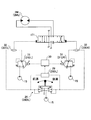
次に、図3を参照し、ショベル100に搭載される油圧システムの構成例について説明する。図3は、ショベル100に搭載される油圧システムの構成例を示す図である。図3は、機械的動力伝達系、作動油ライン、パイロットライン、及び電気制御系を、それぞれ、二重線、実線、破線、及び点線で示している。
Next, a configuration example of a hydraulic system mounted on the excavator 100 will be described with reference to FIG. FIG. 3 is a diagram illustrating a configuration example of a hydraulic system mounted on the excavator 100. FIG. 3 shows a mechanical power transmission system, a hydraulic oil line, a pilot line, and an electric control system by a double line, a solid line, a broken line, and a dotted line, respectively.
ショベル100の油圧システムは、主に、エンジン11、レギュレータ13、メインポンプ14、パイロットポンプ15、コントロールバルブ17、操作装置26、吐出圧センサ28、操作圧センサ29、及びコントローラ30等を含む。
The hydraulic system of the excavator 100 mainly includes an engine 11, a regulator 13, a main pump 14, a pilot pump 15, a control valve 17, an operating device 26, a discharge pressure sensor 28, an operating pressure sensor 29, a controller 30, and the like.
図3において、油圧システムは、エンジン11によって駆動されるメインポンプ14から、センターバイパス管路40又はパラレル管路42を経て作動油タンクまで作動油を循環させることができるように構成されている。
3, the hydraulic system is configured to circulate the hydraulic oil from the main pump 14 driven by the engine 11 to the hydraulic oil tank via the center bypass pipeline 40 or the parallel pipeline 42.
エンジン11は、ショベル100の駆動源である。本実施形態では、エンジン11は、所定の回転数を維持するように動作するディーゼルエンジンである。エンジン11の出力軸は、メインポンプ14及びパイロットポンプ15のそれぞれの入力軸に連結されている。
The engine 11 is a drive source of the excavator 100. In the present embodiment, the engine 11 is a diesel engine that operates so as to maintain a predetermined rotational speed. The output shaft of the engine 11 is connected to the input shafts of the main pump 14 and the pilot pump 15.
メインポンプ14は、作動油ラインを介して作動油をコントロールバルブ17に供給できるように構成されている。本実施形態では、メインポンプ14は、斜板式可変容量型油圧ポンプである。
The main pump 14 is configured to be able to supply hydraulic oil to the control valve 17 via the hydraulic oil line. In the present embodiment, the main pump 14 is a swash plate type variable displacement hydraulic pump.
レギュレータ13は、メインポンプ14の吐出量(押し退け容積)を制御できるように構成されている。本実施形態では、レギュレータ13は、コントローラ30からの制御指令に応じてメインポンプ14の斜板傾転角を調節することによってメインポンプ14の吐出量(押し退け容積)を制御する。
The regulator 13 is configured to control the discharge amount (push-out volume) of the main pump 14. In the present embodiment, the regulator 13 controls the discharge amount (push-out volume) of the main pump 14 by adjusting the swash plate tilt angle of the main pump 14 in accordance with a control command from the controller 30.
パイロットポンプ15は、パイロットラインを介して操作装置26を含む油圧制御機器に作動油を供給できるように構成されている。本実施形態では、パイロットポンプ15は、固定容量型油圧ポンプである。但し、パイロットポンプ15は、省略されてもよい。この場合、パイロットポンプ15が担っていた機能は、メインポンプ14によって実現されてもよい。すなわち、メインポンプ14は、コントロールバルブ17に作動油を供給する機能とは別に、絞り等により作動油の圧力を低下させた後で操作装置26等に作動油を供給する機能を備えていてもよい。
The pilot pump 15 is configured to be able to supply hydraulic oil to a hydraulic control device including the operation device 26 via a pilot line. In the present embodiment, the pilot pump 15 is a fixed displacement hydraulic pump. However, the pilot pump 15 may be omitted. In this case, the function of the pilot pump 15 may be realized by the main pump 14. That is, the main pump 14 may have a function of supplying the operating oil to the operating device 26 after the pressure of the operating oil is reduced by a throttle or the like, in addition to the function of supplying the operating oil to the control valve 17. Good.
コントロールバルブ17は、ショベル100における油圧システムを制御する油圧制御装置である。本実施形態では、コントロールバルブ17は、制御弁171~176を含む。制御弁175は制御弁175L及び制御弁175Rを含み、制御弁176は制御弁176L及び制御弁1756を含む。コントロールバルブ17は、制御弁171~176を通じ、メインポンプ14が吐出する作動油を1又は複数の油圧アクチュエータに選択的に供給できるように構成されている。制御弁171~176は、例えば、メインポンプ14から油圧アクチュエータに流れる作動油の流量、及び、油圧アクチュエータから作動油タンクに流れる作動油の流量を制御する。油圧アクチュエータは、ブームシリンダ7、アームシリンダ8、バケットシリンダ9、左走行油圧モータ2ML、右走行油圧モータ2MR、及び旋回油圧モータ2Aを含む。
The control valve 17 is a hydraulic control device that controls the hydraulic system in the excavator 100. In the present embodiment, the control valve 17 includes control valves 171 to 176. The control valve 175 includes a control valve 175L and a control valve 175R, and the control valve 176 includes a control valve 176L and a control valve 1756. The control valve 17 is configured to selectively supply hydraulic oil discharged from the main pump 14 to one or a plurality of hydraulic actuators through the control valves 171 to 176. The control valves 171 to 176 control, for example, the flow rate of hydraulic fluid that flows from the main pump 14 to the hydraulic actuator, and the flow rate of hydraulic fluid that flows from the hydraulic actuator to the hydraulic oil tank. The hydraulic actuator includes a boom cylinder 7, an arm cylinder 8, a bucket cylinder 9, a left traveling hydraulic motor 2ML, a right traveling hydraulic motor 2MR, and a turning hydraulic motor 2A.
操作装置26は、パイロットラインを介して、パイロットポンプ15が吐出する作動油を、コントロールバルブ17内の対応する制御弁のパイロットポートに供給できるように構成されている。パイロットポートのそれぞれに供給される作動油の圧力(パイロット圧)は、油圧アクチュエータのそれぞれに対応する操作装置26の操作方向及び操作量に応じた圧力である。但し、操作装置26は、上述のようなパイロット圧式ではなく、電気制御式であってもよい。この場合、コントロールバルブ17内の制御弁は、電磁ソレノイド式スプール弁であってもよい。
The operating device 26 is configured to be able to supply the hydraulic oil discharged from the pilot pump 15 to the pilot port of the corresponding control valve in the control valve 17 via the pilot line. The hydraulic oil pressure (pilot pressure) supplied to each pilot port is a pressure corresponding to the operation direction and operation amount of the operation device 26 corresponding to each hydraulic actuator. However, the operating device 26 may be an electric control type instead of the pilot pressure type as described above. In this case, the control valve in the control valve 17 may be an electromagnetic solenoid type spool valve.
吐出圧センサ28は、メインポンプ14の吐出圧を検出できるように構成されている。本実施形態では、吐出圧センサ28は、検出した値をコントローラ30に対して出力する。
The discharge pressure sensor 28 is configured to detect the discharge pressure of the main pump 14. In the present embodiment, the discharge pressure sensor 28 outputs the detected value to the controller 30.
操作圧センサ29は、操作者による操作装置26の操作の内容を検出できるように構成されている。本実施形態では、操作圧センサ29は、アクチュエータのそれぞれに対応する操作装置26の操作方向及び操作量を圧力(操作圧)の形で検出し、検出した値をコントローラ30に対して出力する。操作装置26の操作の内容は、操作圧センサ以外の他のセンサを用いて検出されてもよい。
The operation pressure sensor 29 is configured to detect the content of operation of the operation device 26 by the operator. In the present embodiment, the operation pressure sensor 29 detects the operation direction and operation amount of the operation device 26 corresponding to each of the actuators in the form of pressure (operation pressure), and outputs the detected value to the controller 30. The content of the operation of the operation device 26 may be detected using a sensor other than the operation pressure sensor.
メインポンプ14は、左メインポンプ14L及び右メインポンプ14Rを含む。そして、左メインポンプ14Lは、左センターバイパス管路40L又は左パラレル管路42Lを経て作動油タンクまで作動油を循環させる。右メインポンプ14Rは、右センターバイパス管路40R又は右パラレル管路42Rを経て作動油タンクまで作動油を循環させる。
The main pump 14 includes a left main pump 14L and a right main pump 14R. The left main pump 14L circulates the hydraulic oil to the hydraulic oil tank via the left center bypass pipe 40L or the left parallel pipe 42L. The right main pump 14R circulates the hydraulic oil to the hydraulic oil tank via the right center bypass pipe 40R or the right parallel pipe 42R.
左センターバイパス管路40Lは、コントロールバルブ17内に配置された制御弁171、173、175L、及び176Lを通る作動油ラインである。右センターバイパス管路40Rは、コントロールバルブ17内に配置された制御弁172、174、175R、及び176Rを通る作動油ラインである。
The left center bypass conduit 40L is a hydraulic oil line that passes through control valves 171, 173, 175L, and 176L disposed in the control valve 17. The right center bypass pipeline 40R is a hydraulic oil line that passes through control valves 172, 174, 175R, and 176R disposed in the control valve 17.
制御弁171は、左メインポンプ14Lが吐出する作動油を左走行油圧モータ2MLへ供給し、且つ、左走行油圧モータ2MLが吐出する作動油を作動油タンクへ排出するために作動油の流れを切り換えるスプール弁である。
The control valve 171 supplies the hydraulic oil discharged from the left main pump 14L to the left traveling hydraulic motor 2ML, and discharges the hydraulic oil discharged from the left traveling hydraulic motor 2ML to the hydraulic oil tank. This is a spool valve for switching.
制御弁172は、右メインポンプ14Rが吐出する作動油を右走行油圧モータ2MRへ供給し、且つ、右走行油圧モータ2MRが吐出する作動油を作動油タンクへ排出するために作動油の流れを切り換えるスプール弁である。
The control valve 172 supplies the hydraulic oil discharged from the right main pump 14R to the right traveling hydraulic motor 2MR, and discharges the hydraulic oil discharged from the right traveling hydraulic motor 2MR to the hydraulic oil tank. This is a spool valve for switching.
制御弁173は、左メインポンプ14Lが吐出する作動油を旋回油圧モータ2Aへ供給し、且つ、旋回油圧モータ2Aが吐出する作動油を作動油タンクへ排出するために作動油の流れを切り換えるスプール弁である。
The control valve 173 is a spool that supplies the hydraulic oil discharged from the left main pump 14L to the swing hydraulic motor 2A and switches the flow of the hydraulic oil to discharge the hydraulic oil discharged from the swing hydraulic motor 2A to the hydraulic oil tank. It is a valve.
制御弁174は、右メインポンプ14Rが吐出する作動油をバケットシリンダ9へ供給し、且つ、バケットシリンダ9内の作動油を作動油タンクへ排出するために作動油の流れを切り換えるスプール弁である。
The control valve 174 is a spool valve that supplies the hydraulic oil discharged from the right main pump 14R to the bucket cylinder 9 and switches the flow of the hydraulic oil in order to discharge the hydraulic oil in the bucket cylinder 9 to the hydraulic oil tank. .
制御弁175Lは、左メインポンプ14Lが吐出する作動油をブームシリンダ7へ供給するために作動油の流れを切り換えるスプール弁である。制御弁175Rは、右メインポンプ14Rが吐出する作動油をブームシリンダ7へ供給し、且つ、ブームシリンダ7内の作動油を作動油タンクへ排出するために作動油の流れを切り換えるスプール弁である。
The control valve 175L is a spool valve that switches the flow of the hydraulic oil in order to supply the hydraulic oil discharged from the left main pump 14L to the boom cylinder 7. The control valve 175R is a spool valve that supplies the hydraulic oil discharged from the right main pump 14R to the boom cylinder 7 and switches the flow of the hydraulic oil in order to discharge the hydraulic oil in the boom cylinder 7 to the hydraulic oil tank. .
制御弁176Lは、左メインポンプ14Lが吐出する作動油をアームシリンダ8へ供給し、且つ、アームシリンダ8内の作動油を作動油タンクへ排出するために作動油の流れを切り換えるスプール弁である。
The control valve 176L is a spool valve that supplies the hydraulic oil discharged from the left main pump 14L to the arm cylinder 8 and switches the flow of the hydraulic oil in order to discharge the hydraulic oil in the arm cylinder 8 to the hydraulic oil tank. .
制御弁176Rは、右メインポンプ14Rが吐出する作動油をアームシリンダ8へ供給し、且つ、アームシリンダ8内の作動油を作動油タンクへ排出するために作動油の流れを切り換えるスプール弁である。
The control valve 176R is a spool valve that supplies the hydraulic oil discharged from the right main pump 14R to the arm cylinder 8 and switches the flow of the hydraulic oil in order to discharge the hydraulic oil in the arm cylinder 8 to the hydraulic oil tank. .
左パラレル管路42Lは、左センターバイパス管路40Lに並行する作動油ラインである。左パラレル管路42Lは、制御弁171、173、及び175Lの何れかによって左センターバイパス管路40Lを通る作動油の流れが制限或いは遮断された場合に、より下流の制御弁に作動油を供給できる。右パラレル管路42Rは、右センターバイパス管路40Rに並行する作動油ラインである。右パラレル管路42Rは、制御弁172、174、及び175Rの何れかによって右センターバイパス管路40Rを通る作動油の流れが制限或いは遮断された場合に、より下流の制御弁に作動油を供給できる。
The left parallel pipeline 42L is a hydraulic oil line parallel to the left center bypass pipeline 40L. The left parallel pipe 42L supplies hydraulic oil to the control valve downstream when the flow of hydraulic oil through the left center bypass pipe 40L is restricted or blocked by any of the control valves 171, 173, and 175L. it can. The right parallel pipeline 42R is a hydraulic oil line parallel to the right center bypass pipeline 40R. The right parallel pipe line 42R supplies hydraulic oil to the control valve downstream when the flow of the hydraulic oil passing through the right center bypass pipe line 40R is restricted or blocked by any of the control valves 172, 174, and 175R. it can.
レギュレータ13は、左レギュレータ13L及び右レギュレータ13Rを含む。左レギュレータ13Lは、左メインポンプ14Lの吐出圧に応じて左メインポンプ14Lの斜板傾転角を調節することによって、左メインポンプ14Lの吐出量を制御する。具体的には、左レギュレータ13Lは、例えば、左メインポンプ14Lの吐出圧の増大に応じて左メインポンプ14Lの斜板傾転角を調節して吐出量を減少させる。右レギュレータ13Rについても同様である。吐出圧と吐出量との積で表されるメインポンプ14の吸収パワー(例えば吸収馬力)がエンジン11の出力パワー(例えば出力馬力)を超えないようにするためである。
The regulator 13 includes a left regulator 13L and a right regulator 13R. The left regulator 13L controls the discharge amount of the left main pump 14L by adjusting the swash plate tilt angle of the left main pump 14L according to the discharge pressure of the left main pump 14L. Specifically, the left regulator 13L, for example, adjusts the swash plate tilt angle of the left main pump 14L according to an increase in the discharge pressure of the left main pump 14L, and decreases the discharge amount. The same applies to the right regulator 13R. This is because the absorption power (for example, absorption horsepower) of the main pump 14 represented by the product of the discharge pressure and the discharge amount does not exceed the output power (for example, output horsepower) of the engine 11.
操作装置26は、左操作レバー26L、右操作レバー26R、及び走行レバー26Dを含む。走行レバー26Dは、左走行レバー26DL及び右走行レバー26DRを含む。
The operating device 26 includes a left operating lever 26L, a right operating lever 26R, and a traveling lever 26D. The travel lever 26D includes a left travel lever 26DL and a right travel lever 26DR.
左操作レバー26Lは、旋回操作とアーム5の操作に用いられる。左操作レバー26Lは、前後方向に操作されると、パイロットポンプ15が吐出する作動油を利用し、レバー操作量に応じた制御圧を制御弁176のパイロットポートに導入させる。また、左操作レバー26Lは、左右方向に操作されると、パイロットポンプ15が吐出する作動油を利用し、レバー操作量に応じた制御圧を制御弁173のパイロットポートに導入させる。
The left operation lever 26L is used for turning operation and arm 5 operation. When the left operation lever 26L is operated in the front-rear direction, the hydraulic oil discharged from the pilot pump 15 is used to introduce a control pressure corresponding to the lever operation amount into the pilot port of the control valve 176. Further, when the left operation lever 26L is operated in the left-right direction, the hydraulic oil discharged from the pilot pump 15 is used to introduce a control pressure corresponding to the lever operation amount into the pilot port of the control valve 173.
具体的には、左操作レバー26Lは、アーム閉じ方向に操作された場合に、制御弁176Lの右側パイロットポートに作動油を導入させ、且つ、制御弁176Rの左側パイロットポートに作動油を導入させる。また、左操作レバー26Lは、アーム開き方向に操作された場合には、制御弁176Lの左側パイロットポートに作動油を導入させ、且つ、制御弁176Rの右側パイロットポートに作動油を導入させる。また、左操作レバー26Lは、左旋回方向に操作された場合に、制御弁173の左側パイロットポートに作動油を導入させ、右旋回方向に操作された場合に、制御弁173の右側パイロットポートに作動油を導入させる。
Specifically, the left operating lever 26L introduces hydraulic oil into the right pilot port of the control valve 176L and introduces hydraulic oil into the left pilot port of the control valve 176R when operated in the arm closing direction. . Further, when operated in the arm opening direction, the left operating lever 26L introduces hydraulic oil into the left pilot port of the control valve 176L and introduces hydraulic oil into the right pilot port of the control valve 176R. Further, the left operating lever 26L introduces hydraulic oil into the left pilot port of the control valve 173 when operated in the left turning direction, and the right pilot port of the control valve 173 when operated in the right turning direction. To introduce hydraulic oil.
右操作レバー26Rは、ブーム4の操作とバケット6の操作に用いられる。右操作レバー26Rは、前後方向に操作されると、パイロットポンプ15が吐出する作動油を利用し、レバー操作量に応じた制御圧を制御弁175のパイロットポートに導入させる。また、右操作レバー26Rは、左右方向に操作されると、パイロットポンプ15が吐出する作動油を利用し、レバー操作量に応じた制御圧を制御弁174のパイロットポートに導入させる。
The right operation lever 26R is used for the operation of the boom 4 and the operation of the bucket 6. When the right operation lever 26R is operated in the front-rear direction, the hydraulic oil discharged from the pilot pump 15 is used to introduce a control pressure corresponding to the lever operation amount into the pilot port of the control valve 175. Further, when the right operation lever 26R is operated in the left-right direction, the hydraulic oil discharged from the pilot pump 15 is used to introduce a control pressure corresponding to the lever operation amount into the pilot port of the control valve 174.
具体的には、右操作レバー26Rは、ブーム下げ方向に操作された場合に、制御弁175Rの右側パイロットポートに作動油を導入させる。また、右操作レバー26Rは、ブーム上げ方向に操作された場合には、制御弁175Lの右側パイロットポートに作動油を導入させ、且つ、制御弁175Rの左側パイロットポートに作動油を導入させる。また、右操作レバー26Rは、バケット閉じ方向に操作された場合に、制御弁174の左側パイロットポートに作動油を導入させ、バケット開き方向に操作された場合に、制御弁174の右側パイロットポートに作動油を導入させる。
Specifically, the right operation lever 26R introduces hydraulic oil into the right pilot port of the control valve 175R when operated in the boom lowering direction. Further, when operated in the boom raising direction, the right operating lever 26R introduces hydraulic oil into the right pilot port of the control valve 175L and introduces hydraulic oil into the left pilot port of the control valve 175R. Further, the right operation lever 26R introduces hydraulic oil into the left pilot port of the control valve 174 when operated in the bucket closing direction, and enters the right pilot port of the control valve 174 when operated in the bucket opening direction. Introduce hydraulic fluid.
走行レバー26Dは、クローラ1Cの操作に用いられる。具体的には、左走行レバー26DLは、左クローラ1CLの操作に用いられる。左走行レバー26DLは、左走行ペダルと連動するように構成されていてもよい。左走行レバー26DLは、前後方向に操作されると、パイロットポンプ15が吐出する作動油を利用し、レバー操作量に応じた制御圧を制御弁171のパイロットポートに導入させる。右走行レバー26DRは、右クローラ1CRの操作に用いられる。右走行レバー26DRは、右走行ペダルと連動するように構成されていてもよい。右走行レバー26DRは、前後方向に操作されると、パイロットポンプ15が吐出する作動油を利用し、レバー操作量に応じた制御圧を制御弁172のパイロットポートに導入させる。
The traveling lever 26D is used for the operation of the crawler 1C. Specifically, the left travel lever 26DL is used to operate the left crawler 1CL. The left travel lever 26DL may be configured to be interlocked with the left travel pedal. When the left travel lever 26DL is operated in the front-rear direction, the hydraulic oil discharged from the pilot pump 15 is used to introduce a control pressure corresponding to the lever operation amount into the pilot port of the control valve 171. The right travel lever 26DR is used to operate the right crawler 1CR. The right travel lever 26DR may be configured to be interlocked with the right travel pedal. When the right travel lever 26DR is operated in the front-rear direction, the hydraulic oil discharged from the pilot pump 15 is used to introduce a control pressure corresponding to the lever operation amount into the pilot port of the control valve 172.
吐出圧センサ28は、吐出圧センサ28L及び吐出圧センサ28Rを含む。吐出圧センサ28Lは、左メインポンプ14Lの吐出圧を検出し、検出した値をコントローラ30に対して出力する。吐出圧センサ28Rについても同様である。
The discharge pressure sensor 28 includes a discharge pressure sensor 28L and a discharge pressure sensor 28R. The discharge pressure sensor 28L detects the discharge pressure of the left main pump 14L and outputs the detected value to the controller 30. The same applies to the discharge pressure sensor 28R.
操作圧センサ29は、操作圧センサ29LA、29LB、29RA、29RB、29DL、及び29DRを含む。操作圧センサ29LAは、操作者による左操作レバー26Lに対する前後方向への操作の内容を圧力の形で検出し、検出した値をコントローラ30に対して出力する。操作の内容は、例えば、レバー操作方向及びレバー操作量(レバー操作角度)等である。
The operation pressure sensor 29 includes operation pressure sensors 29LA, 29LB, 29RA, 29RB, 29DL, and 29DR. The operation pressure sensor 29LA detects the content of the operation of the left operation lever 26L by the operator in the front-rear direction in the form of pressure, and outputs the detected value to the controller 30. The contents of the operation include, for example, a lever operation direction and a lever operation amount (lever operation angle).
同様に、操作圧センサ29LBは、操作者による左操作レバー26Lに対する左右方向への操作の内容を圧力の形で検出し、検出した値をコントローラ30に対して出力する。操作圧センサ29RAは、操作者による右操作レバー26Rに対する前後方向への操作の内容を圧力の形で検出し、検出した値をコントローラ30に対して出力する。操作圧センサ29RBは、操作者による右操作レバー26Rに対する左右方向への操作の内容を圧力の形で検出し、検出した値をコントローラ30に対して出力する。操作圧センサ29DLは、操作者による左走行レバー26DLに対する前後方向への操作の内容を圧力の形で検出し、検出した値をコントローラ30に対して出力する。操作圧センサ29DRは、操作者による右走行レバー26DRに対する前後方向への操作の内容を圧力の形で検出し、検出した値をコントローラ30に対して出力する。
Similarly, the operation pressure sensor 29LB detects the content of the operation of the left operation lever 26L by the operator in the left-right direction in the form of pressure, and outputs the detected value to the controller 30. The operation pressure sensor 29RA detects the content of the operation of the right operation lever 26R by the operator in the front-rear direction in the form of pressure, and outputs the detected value to the controller 30. The operation pressure sensor 29RB detects the content of the operation of the right operation lever 26R by the operator in the left-right direction in the form of pressure, and outputs the detected value to the controller 30. The operation pressure sensor 29DL detects the content of the operation of the left travel lever 26DL by the operator in the front-rear direction in the form of pressure, and outputs the detected value to the controller 30. The operation pressure sensor 29DR detects the content of the operation in the front-rear direction on the right travel lever 26DR by the operator in the form of pressure, and outputs the detected value to the controller 30.
コントローラ30は、操作圧センサ29の出力を受信し、必要に応じてレギュレータ13に対して制御指令を出力し、メインポンプ14の吐出量を変化させる。また、コントローラ30は、絞り18の上流に設けられた制御圧センサ19の出力を受信し、必要に応じてレギュレータ13に対して制御指令を出力し、メインポンプ14の吐出量を変化させる。絞り18は左絞り18L及び右絞り18Rを含み、制御圧センサ19は左制御圧センサ19L及び右制御圧センサ19Rを含む。
The controller 30 receives the output of the operation pressure sensor 29, outputs a control command to the regulator 13 as necessary, and changes the discharge amount of the main pump 14. Further, the controller 30 receives the output of the control pressure sensor 19 provided upstream of the throttle 18, outputs a control command to the regulator 13 as necessary, and changes the discharge amount of the main pump 14. The diaphragm 18 includes a left diaphragm 18L and a right diaphragm 18R, and the control pressure sensor 19 includes a left control pressure sensor 19L and a right control pressure sensor 19R.
左センターバイパス管路40Lには、最も下流にある制御弁176Lと作動油タンクとの間に左絞り18Lが配置されている。そのため、左メインポンプ14Lが吐出した作動油の流れは、左絞り18Lで制限される。そして、左絞り18Lは、左レギュレータ13Lを制御するための制御圧を発生させる。左制御圧センサ19Lは、この制御圧を検出するためのセンサであり、検出した値をコントローラ30に対して出力する。コントローラ30は、この制御圧に応じて左メインポンプ14Lの斜板傾転角を調節することによって、左メインポンプ14Lの吐出量を制御する。コントローラ30は、例えば、この制御圧が大きいほど左メインポンプ14Lの吐出量を減少させ、この制御圧が小さいほど左メインポンプ14Lの吐出量を増大させる。右メインポンプ14Rの吐出量も同様に制御される。
In the left center bypass pipe line 40L, a left throttle 18L is disposed between the control valve 176L located at the most downstream side and the hydraulic oil tank. Therefore, the flow of hydraulic oil discharged from the left main pump 14L is limited by the left throttle 18L. The left diaphragm 18L generates a control pressure for controlling the left regulator 13L. The left control pressure sensor 19L is a sensor for detecting this control pressure, and outputs the detected value to the controller 30. The controller 30 controls the discharge amount of the left main pump 14L by adjusting the swash plate tilt angle of the left main pump 14L according to the control pressure. For example, the controller 30 decreases the discharge amount of the left main pump 14L as the control pressure increases, and increases the discharge amount of the left main pump 14L as the control pressure decreases. The discharge amount of the right main pump 14R is similarly controlled.
具体的には、図3で示されるようにショベル100における油圧アクチュエータが何れも操作されていない待機状態の場合、左メインポンプ14Lが吐出する作動油は、左センターバイパス管路40Lを通って左絞り18Lに至る。そして、左メインポンプ14Lが吐出する作動油の流れは、左絞り18Lの上流で発生する制御圧を増大させる。その結果、コントローラ30は、左メインポンプ14Lの吐出量を許容最小吐出量まで減少させ、吐出した作動油が左センターバイパス管路40Lを通過する際の圧力損失(ポンピングロス)を抑制する。一方、何れかの油圧アクチュエータが操作された場合、左メインポンプ14Lが吐出する作動油は、操作対象の油圧アクチュエータに対応する制御弁を介して、操作対象の油圧アクチュエータに流れ込む。そして、左メインポンプ14Lが吐出する作動油の流れは、左絞り18Lに至る量を減少或いは消失させ、左絞り18Lの上流で発生する制御圧を低下させる。その結果、コントローラ30は、左メインポンプ14Lの吐出量を増大させ、操作対象の油圧アクチュエータに十分な作動油を流入させ、操作対象の油圧アクチュエータの駆動を確かなものとする。なお、コントローラ30は、右メインポンプ14Rの吐出量も同様に制御する。
Specifically, as shown in FIG. 3, in the standby state where none of the hydraulic actuators in the excavator 100 is operated, the hydraulic oil discharged from the left main pump 14L passes through the left center bypass conduit 40L to the left. The diaphragm reaches 18L. The flow of hydraulic oil discharged from the left main pump 14L increases the control pressure generated upstream of the left throttle 18L. As a result, the controller 30 reduces the discharge amount of the left main pump 14L to the allowable minimum discharge amount, and suppresses the pressure loss (pumping loss) when the discharged hydraulic oil passes through the left center bypass conduit 40L. On the other hand, when any hydraulic actuator is operated, the hydraulic oil discharged from the left main pump 14L flows into the operation target hydraulic actuator via the control valve corresponding to the operation target hydraulic actuator. The flow of the hydraulic oil discharged from the left main pump 14L reduces or disappears the amount reaching the left throttle 18L, and lowers the control pressure generated upstream of the left throttle 18L. As a result, the controller 30 increases the discharge amount of the left main pump 14L, causes sufficient hydraulic oil to flow into the operation target hydraulic actuator, and ensures the operation of the operation target hydraulic actuator. The controller 30 similarly controls the discharge amount of the right main pump 14R.
上述のような構成により、図3の油圧システムは、待機状態においては、メインポンプ14における無駄なエネルギ消費を抑制できる。無駄なエネルギ消費は、メインポンプ14が吐出する作動油がセンターバイパス管路40で発生させるポンピングロスを含む。また、図3の油圧システムは、油圧アクチュエータを作動させる場合には、メインポンプ14から必要十分な作動油を作動対象の油圧アクチュエータに確実に供給できる。
With the configuration as described above, the hydraulic system of FIG. 3 can suppress wasteful energy consumption in the main pump 14 in the standby state. The wasteful energy consumption includes a pumping loss generated by the hydraulic oil discharged from the main pump 14 in the center bypass conduit 40. 3 can reliably supply necessary and sufficient hydraulic fluid from the main pump 14 to the hydraulic actuator to be operated when the hydraulic actuator is operated.
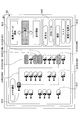
次に、図4A~図4D、図5A、及び図5Bを参照し、コントローラ30がマシンコントロール機能によってアクチュエータを動作させるための構成について説明する。図4A~図4Dは、油圧システムの一部の図である。具体的には、図4Aは、アームシリンダ8の操作に関する油圧システムの一部の図であり、図4Bは、旋回油圧モータ2Aの操作に関する油圧システムの一部の図である。また、図4Cは、ブームシリンダ7の操作に関する油圧システムの一部の図であり、図4Dは、バケットシリンダ9の操作に関する油圧システムの一部の図である。同様に、図5A及び図5Bは、油圧システムの一部の図である。具体的には、図5Aは、左走行油圧モータ2MLの操作に関する油圧システムの一部の図であり、図5Bは、右走行油圧モータ2MRの操作に関する油圧システムの一部の図である。
Next, with reference to FIGS. 4A to 4D, 5A, and 5B, a configuration for the controller 30 to operate the actuator by the machine control function will be described. 4A-4D are diagrams of a portion of the hydraulic system. Specifically, FIG. 4A is a partial view of the hydraulic system related to the operation of the arm cylinder 8, and FIG. 4B is a partial view of the hydraulic system related to the operation of the swing hydraulic motor 2A. 4C is a diagram of a part of the hydraulic system related to the operation of the boom cylinder 7, and FIG. 4D is a diagram of a part of the hydraulic system related to the operation of the bucket cylinder 9. Similarly, FIGS. 5A and 5B are diagrams of a portion of a hydraulic system. Specifically, FIG. 5A is a diagram of a part of the hydraulic system related to the operation of the left travel hydraulic motor 2ML, and FIG. 5B is a diagram of a part of the hydraulic system related to the operation of the right travel hydraulic motor 2MR.
図4A~図4D、図5A、及び図5Bに示すように、油圧システムは、比例弁31及びシャトル弁32を含む。比例弁31は、比例弁31AL~31FL及び31AR~31FRを含み、シャトル弁32は、シャトル弁32AL~32FL及び32AR~32FRを含む。
4A-4D, 5A, and 5B, the hydraulic system includes a proportional valve 31 and a shuttle valve 32. The proportional valve 31 includes proportional valves 31AL to 31FL and 31AR to 31FR, and the shuttle valve 32 includes shuttle valves 32AL to 32FL and 32AR to 32FR.
比例弁31は、マシンコントロール用制御弁として機能するように構成されている。比例弁31は、パイロットポンプ15とシャトル弁32とを接続する管路に配置され、その管路の流路面積を変更できるように構成されている。本実施形態では、比例弁31は、コントローラ30が出力する制御指令に応じて動作する。そのため、コントローラ30は、操作者による操作装置26の操作とは無関係に、パイロットポンプ15が吐出する作動油を、比例弁31及びシャトル弁32を介し、コントロールバルブ17内の対応する制御弁のパイロットポートに供給できる。
The proportional valve 31 is configured to function as a control valve for machine control. The proportional valve 31 is arranged in a pipe line connecting the pilot pump 15 and the shuttle valve 32, and is configured so that the flow path area of the pipe line can be changed. In the present embodiment, the proportional valve 31 operates according to a control command output from the controller 30. Therefore, the controller 30 controls the pilot oil of the corresponding control valve in the control valve 17 through the proportional valve 31 and the shuttle valve 32 via the proportional valve 31 and the shuttle valve 32, regardless of the operation of the operating device 26 by the operator. Can be supplied to the port.
シャトル弁32は、2つの入口ポートと1つの出口ポートを有する。2つの入口ポートのうちの一方は操作装置26に接続され、他方は比例弁31に接続されている。出口ポートは、コントロールバルブ17内の対応する制御弁のパイロットポートに接続されている。そのため、シャトル弁32は、操作装置26が生成するパイロット圧と比例弁31が生成するパイロット圧のうちの高い方を、対応する制御弁のパイロットポートに作用させることができる。
The shuttle valve 32 has two inlet ports and one outlet port. One of the two inlet ports is connected to the operating device 26, and the other is connected to the proportional valve 31. The outlet port is connected to the pilot port of the corresponding control valve in the control valve 17. Therefore, the shuttle valve 32 can cause the higher one of the pilot pressure generated by the operating device 26 and the pilot pressure generated by the proportional valve 31 to act on the pilot port of the corresponding control valve.
この構成により、コントローラ30は、特定の操作装置26に対する操作が行われていない場合であっても、その特定の操作装置26に対応する油圧アクチュエータを動作させることができる。
With this configuration, the controller 30 can operate the hydraulic actuator corresponding to the specific operation device 26 even when the operation to the specific operation device 26 is not performed.
例えば、図4Aに示すように、左操作レバー26Lは、アーム5を操作するために用いられる。具体的には、左操作レバー26Lは、パイロットポンプ15が吐出する作動油を利用し、前後方向への操作に応じたパイロット圧を制御弁176のパイロットポートに作用させる。より具体的には、左操作レバー26Lは、アーム閉じ方向(後方向)に操作された場合に、操作量に応じたパイロット圧を制御弁176Lの右側パイロットポートと制御弁176Rの左側パイロットポートに作用させる。また、左操作レバー26Lは、アーム開き方向(前方向)に操作された場合には、操作量に応じたパイロット圧を制御弁176Lの左側パイロットポートと制御弁176Rの右側パイロットポートに作用させる。
For example, as shown in FIG. 4A, the left operation lever 26L is used to operate the arm 5. Specifically, the left operation lever 26L uses the hydraulic oil discharged from the pilot pump 15 to apply a pilot pressure corresponding to the operation in the front-rear direction to the pilot port of the control valve 176. More specifically, when the left operation lever 26L is operated in the arm closing direction (rearward direction), the pilot pressure corresponding to the operation amount is applied to the right pilot port of the control valve 176L and the left pilot port of the control valve 176R. Make it work. Further, when the left operation lever 26L is operated in the arm opening direction (forward direction), the pilot pressure corresponding to the operation amount is applied to the left pilot port of the control valve 176L and the right pilot port of the control valve 176R.
左操作レバー26LにはスイッチNSが設けられている。本実施形態では、スイッチNSは、押しボタンスイッチである。操作者は、スイッチNSを指で押しながら左操作レバー26Lを手で操作できる。スイッチNSは、右操作レバー26Rに設けられていてもよく、キャビン10内の他の位置に設けられていてもよい。
The left operation lever 26L is provided with a switch NS. In the present embodiment, the switch NS is a push button switch. The operator can manually operate the left operation lever 26L while pressing the switch NS with a finger. The switch NS may be provided on the right operation lever 26 </ b> R, or may be provided at another position in the cabin 10.
操作圧センサ29LAは、操作者による左操作レバー26Lに対する前後方向への操作の内容を圧力の形で検出し、検出した値をコントローラ30に対して出力する。
The operation pressure sensor 29LA detects the content of the operation of the left operation lever 26L by the operator in the front-rear direction in the form of pressure, and outputs the detected value to the controller 30.
比例弁31ALは、コントローラ30が出力する電流指令に応じて動作する。そして、比例弁31ALは、パイロットポンプ15から比例弁31AL及びシャトル弁32ALを介して制御弁176Lの右側パイロットポート及び制御弁176Rの左側パイロットポートに導入される作動油によるパイロット圧を調整する。比例弁31ARは、コントローラ30が出力する電流指令に応じて動作する。そして、比例弁31ARは、パイロットポンプ15から比例弁31AR及びシャトル弁32ARを介して制御弁176Lの左側パイロットポート及び制御弁176Rの右側パイロットポートに導入される作動油によるパイロット圧を調整する。比例弁31AL及び31ARのそれぞれは、制御弁176を任意の弁位置で停止できるようにパイロット圧を調整可能である。
The proportional valve 31AL operates according to the current command output from the controller 30. The proportional valve 31AL adjusts the pilot pressure by the hydraulic oil introduced from the pilot pump 15 to the right pilot port of the control valve 176L and the left pilot port of the control valve 176R via the proportional valve 31AL and the shuttle valve 32AL. The proportional valve 31AR operates in accordance with a current command output from the controller 30. The proportional valve 31AR adjusts the pilot pressure by the hydraulic oil introduced from the pilot pump 15 to the left pilot port of the control valve 176L and the right pilot port of the control valve 176R via the proportional valve 31AR and the shuttle valve 32AR. Each of the proportional valves 31AL and 31AR can adjust the pilot pressure so that the control valve 176 can be stopped at an arbitrary valve position.
この構成により、コントローラ30は、操作者によるアーム閉じ操作とは無関係に、パイロットポンプ15が吐出する作動油を、比例弁31AL及びシャトル弁32ALを介し、制御弁176Lの右側パイロットポート及び制御弁176Rの左側パイロットポートに供給できる。すなわち、コントローラ30は、操作者によるアーム閉じ操作とは無関係に、アーム5を閉じることができる。また、コントローラ30は、操作者によるアーム開き操作とは無関係に、パイロットポンプ15が吐出する作動油を、比例弁31AR及びシャトル弁32ARを介し、制御弁176Lの左側パイロットポート及び制御弁176Rの右側パイロットポートに供給できる。すなわち、コントローラ30は、操作者によるアーム開き操作とは無関係に、アーム5を開くことができる。
With this configuration, the controller 30 allows the hydraulic oil discharged from the pilot pump 15 to flow through the proportional valve 31AL and the shuttle valve 32AL, regardless of the arm closing operation by the operator, and to the right pilot port and the control valve 176R of the control valve 176L. Can be supplied to the left pilot port. That is, the controller 30 can close the arm 5 regardless of the arm closing operation by the operator. Further, the controller 30 supplies the hydraulic oil discharged from the pilot pump 15 to the left pilot port of the control valve 176L and the right side of the control valve 176R via the proportional valve 31AR and the shuttle valve 32AR regardless of the arm opening operation by the operator. Can be supplied to the pilot port. That is, the controller 30 can open the arm 5 regardless of the arm opening operation by the operator.
また、図4Bに示すように、左操作レバー26Lは、旋回機構2を操作するためにも用いられる。具体的には、左操作レバー26Lは、パイロットポンプ15が吐出する作動油を利用し、左右方向への操作に応じたパイロット圧を制御弁173のパイロットポートに作用させる。より具体的には、左操作レバー26Lは、左旋回方向(左方向)に操作された場合に、操作量に応じたパイロット圧を制御弁173の左側パイロットポートに作用させる。また、左操作レバー26Lは、右旋回方向(右方向)に操作された場合には、操作量に応じたパイロット圧を制御弁173の右側パイロットポートに作用させる。
Further, as shown in FIG. 4B, the left operation lever 26L is also used to operate the turning mechanism 2. Specifically, the left operation lever 26L uses the hydraulic oil discharged from the pilot pump 15 to apply a pilot pressure corresponding to the operation in the left-right direction to the pilot port of the control valve 173. More specifically, the left operation lever 26L causes a pilot pressure corresponding to the operation amount to act on the left pilot port of the control valve 173 when operated in the left turning direction (left direction). Further, when the left operation lever 26L is operated in the right turning direction (right direction), the pilot pressure corresponding to the operation amount is applied to the right pilot port of the control valve 173.
操作圧センサ29LBは、操作者による左操作レバー26Lに対する左右方向への操作の内容を圧力の形で検出し、検出した値をコントローラ30に対して出力する。
The operation pressure sensor 29LB detects the content of the operation of the left operation lever 26L by the operator in the left-right direction in the form of pressure, and outputs the detected value to the controller 30.
比例弁31BLは、コントローラ30が出力する電流指令に応じて動作する。そして、比例弁31BLは、パイロットポンプ15から比例弁31BL及びシャトル弁32BLを介して制御弁173の左側パイロットポートに導入される作動油によるパイロット圧を調整する。比例弁31BRは、コントローラ30が出力する電流指令に応じて動作する。そして、比例弁31BRは、パイロットポンプ15から比例弁31BR及びシャトル弁32BRを介して制御弁173の右側パイロットポートに導入される作動油によるパイロット圧を調整する。比例弁31BL及び31BRのそれぞれは、制御弁173を任意の弁位置で停止できるようにパイロット圧を調整可能である。
The proportional valve 31BL operates according to a current command output from the controller 30. The proportional valve 31BL adjusts the pilot pressure by the hydraulic oil introduced from the pilot pump 15 to the left pilot port of the control valve 173 via the proportional valve 31BL and the shuttle valve 32BL. The proportional valve 31BR operates in accordance with a current command output from the controller 30. The proportional valve 31BR adjusts the pilot pressure by the hydraulic oil introduced from the pilot pump 15 to the right pilot port of the control valve 173 via the proportional valve 31BR and the shuttle valve 32BR. Each of the proportional valves 31BL and 31BR can adjust the pilot pressure so that the control valve 173 can be stopped at an arbitrary valve position.
この構成により、コントローラ30は、操作者による左旋回操作とは無関係に、パイロットポンプ15が吐出する作動油を、比例弁31BL及びシャトル弁32BLを介し、制御弁173の左側パイロットポートに供給できる。すなわち、コントローラ30は、操作者による左旋回操作とは無関係に、旋回機構2を左旋回させることができる。また、コントローラ30は、操作者による右旋回操作とは無関係に、パイロットポンプ15が吐出する作動油を、比例弁31BR及びシャトル弁32BRを介し、制御弁173の右側パイロットポートに供給できる。すなわち、コントローラ30は、操作者による右旋回操作とは無関係に、旋回機構2を右旋回させることができる。
With this configuration, the controller 30 can supply the hydraulic oil discharged from the pilot pump 15 to the left pilot port of the control valve 173 via the proportional valve 31BL and the shuttle valve 32BL regardless of the left turning operation by the operator. That is, the controller 30 can turn the turning mechanism 2 to the left regardless of the left turning operation by the operator. Further, the controller 30 can supply the hydraulic oil discharged from the pilot pump 15 to the right pilot port of the control valve 173 via the proportional valve 31BR and the shuttle valve 32BR regardless of the right turning operation by the operator. That is, the controller 30 can turn the turning mechanism 2 to the right regardless of the right turning operation by the operator.
また、図4Cに示すように、右操作レバー26Rは、ブーム4を操作するために用いられる。具体的には、右操作レバー26Rは、パイロットポンプ15が吐出する作動油を利用し、前後方向への操作に応じたパイロット圧を制御弁175のパイロットポートに作用させる。より具体的には、右操作レバー26Rは、ブーム上げ方向(後方向)に操作された場合に、操作量に応じたパイロット圧を制御弁175Lの右側パイロットポートと制御弁175Rの左側パイロットポートに作用させる。また、右操作レバー26Rは、ブーム下げ方向(前方向)に操作された場合には、操作量に応じたパイロット圧を制御弁175Rの右側パイロットポートに作用させる。
Further, as shown in FIG. 4C, the right operation lever 26R is used to operate the boom 4. Specifically, the right operation lever 26R uses the hydraulic oil discharged from the pilot pump 15 to apply a pilot pressure corresponding to the operation in the front-rear direction to the pilot port of the control valve 175. More specifically, when the right operation lever 26R is operated in the boom raising direction (rearward direction), the pilot pressure corresponding to the operation amount is applied to the right pilot port of the control valve 175L and the left pilot port of the control valve 175R. Make it work. Further, when the right operation lever 26R is operated in the boom lowering direction (forward direction), the pilot pressure corresponding to the operation amount is applied to the right pilot port of the control valve 175R.
操作圧センサ29RAは、操作者による右操作レバー26Rに対する前後方向への操作の内容を圧力の形で検出し、検出した値をコントローラ30に対して出力する。
The operation pressure sensor 29RA detects the content of the operation of the right operation lever 26R by the operator in the front-rear direction in the form of pressure, and outputs the detected value to the controller 30.
比例弁31CLは、コントローラ30が出力する電流指令に応じて動作する。そして、比例弁31CLは、パイロットポンプ15から比例弁31CL及びシャトル弁32CLを介して制御弁175Lの右側パイロットポート及び制御弁175Rの左側パイロットポートに導入される作動油によるパイロット圧を調整する。比例弁31CRは、コントローラ30が出力する電流指令に応じて動作する。そして、比例弁31CRは、パイロットポンプ15から比例弁31CR及びシャトル弁32CRを介して制御弁175Lの左側パイロットポート及び制御弁175Rの右側パイロットポートに導入される作動油によるパイロット圧を調整する。比例弁31CL及び31CRのそれぞれは、制御弁175を任意の弁位置で停止できるようにパイロット圧を調整可能である。
The proportional valve 31CL operates in accordance with a current command output from the controller 30. The proportional valve 31CL adjusts the pilot pressure by the hydraulic oil introduced from the pilot pump 15 to the right pilot port of the control valve 175L and the left pilot port of the control valve 175R via the proportional valve 31CL and the shuttle valve 32CL. The proportional valve 31CR operates in accordance with a current command output from the controller 30. The proportional valve 31CR adjusts the pilot pressure by the hydraulic oil introduced from the pilot pump 15 to the left pilot port of the control valve 175L and the right pilot port of the control valve 175R via the proportional valve 31CR and the shuttle valve 32CR. Each of the proportional valves 31CL and 31CR can adjust the pilot pressure so that the control valve 175 can be stopped at an arbitrary valve position.
この構成により、コントローラ30は、操作者によるブーム上げ操作とは無関係に、パイロットポンプ15が吐出する作動油を、比例弁31CL及びシャトル弁32CLを介し、制御弁175Lの右側パイロットポート及び制御弁175Rの左側パイロットポートに供給できる。すなわち、コントローラ30は、操作者によるブーム上げ操作とは無関係に、ブーム4を上げることができる。また、コントローラ30は、操作者によるブーム下げ操作とは無関係に、パイロットポンプ15が吐出する作動油を、比例弁31CR及びシャトル弁32CRを介し、制御弁175Rの右側パイロットポートに供給できる。すなわち、コントローラ30は、操作者によるブーム下げ操作とは無関係に、ブーム4を下げることができる。
With this configuration, the controller 30 allows the hydraulic oil discharged from the pilot pump 15 to flow through the proportional valve 31CL and the shuttle valve 32CL, regardless of the boom raising operation by the operator, and the right pilot port and the control valve 175R of the control valve 175L. Can be supplied to the left pilot port. That is, the controller 30 can raise the boom 4 regardless of the boom raising operation by the operator. Further, the controller 30 can supply the hydraulic oil discharged from the pilot pump 15 to the right pilot port of the control valve 175R via the proportional valve 31CR and the shuttle valve 32CR regardless of the boom lowering operation by the operator. That is, the controller 30 can lower the boom 4 regardless of the boom lowering operation by the operator.
また、図4Dに示すように、右操作レバー26Rは、バケット6を操作するためにも用いられる。具体的には、右操作レバー26Rは、パイロットポンプ15が吐出する作動油を利用し、左右方向への操作に応じたパイロット圧を制御弁174のパイロットポートに作用させる。より具体的には、右操作レバー26Rは、バケット閉じ方向(左方向)に操作された場合に、操作量に応じたパイロット圧を制御弁174の左側パイロットポートに作用させる。また、右操作レバー26Rは、バケット開き方向(右方向)に操作された場合には、操作量に応じたパイロット圧を制御弁174の右側パイロットポートに作用させる。
Further, as shown in FIG. 4D, the right operation lever 26R is also used to operate the bucket 6. Specifically, the right operation lever 26R uses the hydraulic oil discharged from the pilot pump 15 to apply a pilot pressure corresponding to the operation in the left-right direction to the pilot port of the control valve 174. More specifically, the right operation lever 26R applies a pilot pressure corresponding to the operation amount to the left pilot port of the control valve 174 when operated in the bucket closing direction (left direction). Further, when the right operation lever 26R is operated in the bucket opening direction (right direction), the pilot pressure corresponding to the operation amount is applied to the right pilot port of the control valve 174.
操作圧センサ29RBは、操作者による右操作レバー26Rに対する左右方向への操作の内容を圧力の形で検出し、検出した値をコントローラ30に対して出力する。
The operation pressure sensor 29RB detects the content of the operation of the right operation lever 26R by the operator in the left-right direction in the form of pressure, and outputs the detected value to the controller 30.
比例弁31DLは、コントローラ30が出力する電流指令に応じて動作する。そして、比例弁31DLは、パイロットポンプ15から比例弁31DL及びシャトル弁32DLを介して制御弁174の左側パイロットポートに導入される作動油によるパイロット圧を調整する。比例弁31DRは、コントローラ30が出力する電流指令に応じて動作する。そして、比例弁31DRは、パイロットポンプ15から比例弁31DR及びシャトル弁32DRを介して制御弁174の右側パイロットポートに導入される作動油によるパイロット圧を調整する。比例弁31DL及び31DRのそれぞれは、制御弁174を任意の弁位置で停止できるようにパイロット圧を調整可能である。
The proportional valve 31DL operates in accordance with a current command output from the controller 30. The proportional valve 31DL adjusts the pilot pressure by the hydraulic oil introduced from the pilot pump 15 to the left pilot port of the control valve 174 via the proportional valve 31DL and the shuttle valve 32DL. The proportional valve 31DR operates in accordance with a current command output from the controller 30. The proportional valve 31DR adjusts the pilot pressure by the hydraulic oil introduced from the pilot pump 15 to the right pilot port of the control valve 174 via the proportional valve 31DR and the shuttle valve 32DR. Each of the proportional valves 31DL and 31DR can adjust the pilot pressure so that the control valve 174 can be stopped at an arbitrary valve position.
この構成により、コントローラ30は、操作者によるバケット閉じ操作とは無関係に、パイロットポンプ15が吐出する作動油を、比例弁31DL及びシャトル弁32DLを介し、制御弁174の左側パイロットポートに供給できる。すなわち、コントローラ30は、操作者によるバケット閉じ操作とは無関係に、バケット6を閉じることができる。また、コントローラ30は、操作者によるバケット開き操作とは無関係に、パイロットポンプ15が吐出する作動油を、比例弁31DR及びシャトル弁32DRを介し、制御弁174の右側パイロットポートに供給できる。すなわち、コントローラ30は、操作者によるバケット開き操作とは無関係に、バケット6を開くことができる。
With this configuration, the controller 30 can supply the hydraulic oil discharged from the pilot pump 15 to the left pilot port of the control valve 174 via the proportional valve 31DL and the shuttle valve 32DL regardless of the bucket closing operation by the operator. That is, the controller 30 can close the bucket 6 regardless of the bucket closing operation by the operator. Further, the controller 30 can supply the hydraulic oil discharged from the pilot pump 15 to the right pilot port of the control valve 174 via the proportional valve 31DR and the shuttle valve 32DR regardless of the bucket opening operation by the operator. That is, the controller 30 can open the bucket 6 regardless of the bucket opening operation by the operator.
また、図5Aに示すように、左走行レバー26DLは、左クローラ1CLを操作するために用いられる。具体的には、左走行レバー26DLは、パイロットポンプ15が吐出する作動油を利用し、前後方向への操作に応じたパイロット圧を制御弁171のパイロットポートに作用させる。より具体的には、左走行レバー26DLは、前進方向(前方向)に操作された場合に、操作量に応じたパイロット圧を制御弁171の左側パイロットポートに作用させる。また、左走行レバー26DLは、後進方向(後方向)に操作された場合には、操作量に応じたパイロット圧を制御弁171の右側パイロットポートに作用させる。
Also, as shown in FIG. 5A, the left travel lever 26DL is used to operate the left crawler 1CL. Specifically, the left travel lever 26DL uses the hydraulic oil discharged from the pilot pump 15 to apply a pilot pressure corresponding to the operation in the front-rear direction to the pilot port of the control valve 171. More specifically, the left travel lever 26DL applies a pilot pressure corresponding to the operation amount to the left pilot port of the control valve 171 when operated in the forward direction (forward direction). Further, when the left travel lever 26DL is operated in the reverse direction (rearward direction), the pilot pressure corresponding to the operation amount is applied to the right pilot port of the control valve 171.
操作圧センサ29DLは、操作者による左走行レバー26DLに対する前後方向への操作の内容を圧力の形で検出し、検出した値をコントローラ30に対して出力する。
The operation pressure sensor 29DL detects the content of the operation of the left traveling lever 26DL by the operator in the front-rear direction in the form of pressure, and outputs the detected value to the controller 30.
比例弁31ELは、コントローラ30が出力する電流指令に応じて動作する。そして、比例弁31ELは、パイロットポンプ15から比例弁31EL及びシャトル弁32ELを介して制御弁171の左側パイロットポートに導入される作動油によるパイロット圧を調整する。比例弁31ERは、コントローラ30が出力する電流指令に応じて動作する。そして、比例弁31ERは、パイロットポンプ15から比例弁31ER及びシャトル弁32ERを介して制御弁171の右側パイロットポートに導入される作動油によるパイロット圧を調整する。比例弁31EL及び31ERのそれぞれは、制御弁171を任意の弁位置で停止できるようにパイロット圧を調整可能である。
The proportional valve 31EL operates according to the current command output from the controller 30. The proportional valve 31EL adjusts the pilot pressure by the hydraulic oil introduced from the pilot pump 15 to the left pilot port of the control valve 171 via the proportional valve 31EL and the shuttle valve 32EL. The proportional valve 31ER operates in accordance with a current command output from the controller 30. The proportional valve 31ER adjusts the pilot pressure by the hydraulic oil introduced from the pilot pump 15 to the right pilot port of the control valve 171 via the proportional valve 31ER and the shuttle valve 32ER. Each of the proportional valves 31EL and 31ER can adjust the pilot pressure so that the control valve 171 can be stopped at an arbitrary valve position.
この構成により、コントローラ30は、操作者による左前進操作とは無関係に、パイロットポンプ15が吐出する作動油を、比例弁31EL及びシャトル弁32ELを介し、制御弁171の左側パイロットポートに供給できる。すなわち、コントローラ30は、操作者による左前進操作とは無関係に、左クローラ1CLを前進させることができる。また、コントローラ30は、操作者による左後進操作とは無関係に、パイロットポンプ15が吐出する作動油を、比例弁31ER及びシャトル弁32ERを介し、制御弁171の右側パイロットポートに供給できる。すなわち、コントローラ30は、操作者による左後進操作とは無関係に、左クローラ1CLを後進させることができる。
With this configuration, the controller 30 can supply the hydraulic oil discharged from the pilot pump 15 to the left pilot port of the control valve 171 via the proportional valve 31EL and the shuttle valve 32EL, regardless of the left forward operation by the operator. That is, the controller 30 can move the left crawler 1CL forward regardless of the left forward operation by the operator. Further, the controller 30 can supply the hydraulic oil discharged from the pilot pump 15 to the right pilot port of the control valve 171 via the proportional valve 31ER and the shuttle valve 32ER, regardless of the left reverse operation by the operator. That is, the controller 30 can reverse the left crawler 1CL regardless of the left reverse operation by the operator.
また、図5Bに示すように、右走行レバー26DRは、右クローラ1CRを操作するために用いられる。具体的には、右走行レバー26DRは、パイロットポンプ15が吐出する作動油を利用し、前後方向への操作に応じたパイロット圧を制御弁172のパイロットポートに作用させる。より具体的には、右走行レバー26DRは、前進方向(前方向)に操作された場合に、操作量に応じたパイロット圧を制御弁172の右側パイロットポートに作用させる。また、右走行レバー26DRは、後進方向(後方向)に操作された場合には、操作量に応じたパイロット圧を制御弁172の左側パイロットポートに作用させる。
Further, as shown in FIG. 5B, the right travel lever 26DR is used to operate the right crawler 1CR. Specifically, the right travel lever 26DR uses the hydraulic oil discharged from the pilot pump 15 to apply a pilot pressure corresponding to the operation in the front-rear direction to the pilot port of the control valve 172. More specifically, when the right travel lever 26DR is operated in the forward direction (forward direction), the pilot pressure corresponding to the operation amount is applied to the right pilot port of the control valve 172. Further, when the right travel lever 26DR is operated in the reverse direction (rearward direction), the pilot pressure corresponding to the operation amount is applied to the left pilot port of the control valve 172.
操作圧センサ29DRは、操作者による右走行レバー26DRに対する前後方向への操作の内容を圧力の形で検出し、検出した値をコントローラ30に対して出力する。
The operation pressure sensor 29DR detects the content of the operation of the right travel lever 26DR by the operator in the front-rear direction in the form of pressure, and outputs the detected value to the controller 30.
比例弁31FLは、コントローラ30が出力する電流指令に応じて動作する。そして、比例弁31FLは、パイロットポンプ15から比例弁31FL及びシャトル弁32FLを介して制御弁172の左側パイロットポートに導入される作動油によるパイロット圧を調整する。比例弁31FRは、コントローラ30が出力する電流指令に応じて動作する。そして、比例弁31FRは、パイロットポンプ15から比例弁31FR及びシャトル弁32FRを介して制御弁172の右側パイロットポートに導入される作動油によるパイロット圧を調整する。比例弁31FL及び31FRのそれぞれは、制御弁172を任意の弁位置で停止できるようにパイロット圧を調整可能である。
The proportional valve 31FL operates according to a current command output from the controller 30. The proportional valve 31FL adjusts the pilot pressure by the hydraulic oil introduced from the pilot pump 15 to the left pilot port of the control valve 172 via the proportional valve 31FL and the shuttle valve 32FL. The proportional valve 31FR operates in accordance with a current command output from the controller 30. The proportional valve 31FR adjusts the pilot pressure by the hydraulic oil introduced from the pilot pump 15 to the right pilot port of the control valve 172 via the proportional valve 31FR and the shuttle valve 32FR. Each of the proportional valves 31FL and 31FR can adjust the pilot pressure so that the control valve 172 can be stopped at an arbitrary valve position.
この構成により、コントローラ30は、操作者による右前進操作とは無関係に、パイロットポンプ15が吐出する作動油を、比例弁31FL及びシャトル弁32FLを介し、制御弁172の右側パイロットポートに供給できる。すなわち、コントローラ30は、操作者による右前進操作とは無関係に、右クローラ1CRを前進させることができる。また、コントローラ30は、操作者による右後進操作とは無関係に、パイロットポンプ15が吐出する作動油を、比例弁31FR及びシャトル弁32FRを介し、制御弁172の左側パイロットポートに供給できる。すなわち、コントローラ30は、操作者による右後進操作とは無関係に、右クローラ1CRを後進させることができる。
With this configuration, the controller 30 can supply the hydraulic oil discharged from the pilot pump 15 to the right pilot port of the control valve 172 via the proportional valve 31FL and the shuttle valve 32FL regardless of the right forward operation by the operator. That is, the controller 30 can move the right crawler 1CR forward irrespective of the right forward operation by the operator. Further, the controller 30 can supply the hydraulic oil discharged from the pilot pump 15 to the left pilot port of the control valve 172 via the proportional valve 31FR and the shuttle valve 32FR regardless of the right reverse operation by the operator. That is, the controller 30 can move the right crawler 1CR backward irrespective of the right reverse operation by the operator.
なお、上述の実施形態では、油圧式パイロット回路を備えた油圧式操作レバーが採用されているが、このような油圧式パイロット回路を備えた油圧式操作レバーではなく、電気式パイロット回路を備えた電気式操作レバーが採用されてもよい。この場合、電気式操作レバーのレバー操作量は、電気信号としてコントローラ30へ入力される。また、パイロットポンプ15と各制御弁のパイロットポートとの間には電磁弁が配置される。電磁弁は、コントローラ30からの電気信号に応じて動作するように構成される。この構成により、電気式操作レバーを用いた手動操作が行われると、コントローラ30は、レバー操作量に対応する電気信号によって電磁弁を制御してパイロット圧を増減させることで各制御弁を移動させることができる。なお、各制御弁は電磁スプール弁で構成されていてもよい。この場合、電磁スプール弁は、電気式操作レバーのレバー操作量に対応するコントローラ30からの電気信号に応じて動作する。
In the above-described embodiment, a hydraulic operation lever having a hydraulic pilot circuit is employed, but an electric pilot circuit is provided instead of a hydraulic operation lever having such a hydraulic pilot circuit. An electric operation lever may be employed. In this case, the lever operation amount of the electric operation lever is input to the controller 30 as an electric signal. An electromagnetic valve is disposed between the pilot pump 15 and the pilot port of each control valve. The solenoid valve is configured to operate in response to an electrical signal from the controller 30. With this configuration, when a manual operation using an electric operation lever is performed, the controller 30 moves each control valve by controlling the electromagnetic valve with an electric signal corresponding to the lever operation amount to increase or decrease the pilot pressure. be able to. Each control valve may be constituted by an electromagnetic spool valve. In this case, the electromagnetic spool valve operates in accordance with an electric signal from the controller 30 corresponding to the lever operation amount of the electric operation lever.
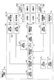
次に、図6を参照し、コントローラ30の機能について説明する。図6は、コントローラ30の構成例を示す機能ブロック図である。図6の例では、コントローラ30は、姿勢検出装置、操作装置26、空間認識装置70、向き検出装置71、情報入力装置72、測位装置73、及びスイッチNS等の少なくとも1つが出力する信号を受け、様々な演算を実行し、比例弁31、表示装置D1、及び音出力装置D2等の少なくとも1つに制御指令を出力できるように構成されている。姿勢検出装置は、ブーム角度センサS1、アーム角度センサS2、バケット角度センサS3、機体傾斜センサS4、及び旋回角速度センサS5を含む。コントローラ30は、各種機能を担う機能要素として、姿勢検出部30A、判定部30B、及び自律制御部30Cを有する。各機能要素は、ハードウェアで構成されていてもよく、ソフトウェアで構成されていてもよい。
Next, the function of the controller 30 will be described with reference to FIG. FIG. 6 is a functional block diagram illustrating a configuration example of the controller 30. In the example of FIG. 6, the controller 30 receives a signal output from at least one of the posture detection device, the operation device 26, the space recognition device 70, the orientation detection device 71, the information input device 72, the positioning device 73, the switch NS, and the like. Various operations are executed, and a control command can be output to at least one of the proportional valve 31, the display device D1, the sound output device D2, and the like. The attitude detection device includes a boom angle sensor S1, an arm angle sensor S2, a bucket angle sensor S3, a body tilt sensor S4, and a turning angular velocity sensor S5. The controller 30 includes a posture detection unit 30A, a determination unit 30B, and an autonomous control unit 30C as functional elements that perform various functions. Each functional element may be configured by hardware or may be configured by software.
姿勢検出部30Aは、ショベル100の姿勢に関する情報を検出するように構成されている。本実施形態では、姿勢検出部30Aは、姿勢検出装置の出力に基づき、ショベル100の姿勢に関する情報を検出する。姿勢検出部30Aは、姿勢検出装置の出力に基づき、ショベル100の姿勢として掘削アタッチメントATの姿勢を検出してもよい。また、姿勢検出部30Aは、姿勢検出装置及び向き検出装置の少なくとも1つの出力に基づき、ショベル100の姿勢として上部旋回体3の姿勢(下部走行体1の向きに対する上部旋回体3の向き)を検出してもよい。
The posture detection unit 30A is configured to detect information related to the posture of the excavator 100. In the present embodiment, the posture detection unit 30A detects information related to the posture of the excavator 100 based on the output of the posture detection device. The posture detection unit 30A may detect the posture of the excavation attachment AT as the posture of the excavator 100 based on the output of the posture detection device. Further, the posture detection unit 30A determines the posture of the upper swing body 3 (the direction of the upper swing body 3 relative to the direction of the lower traveling body 1) as the position of the excavator 100 based on at least one output of the posture detection device and the direction detection device. It may be detected.
判定部30Bは、所望の空間の存否を判定できるように構成されている。本実施形態では、判定部30Bは、ショベル100を駐車させることができる空間である駐車スペースの存否、及び、ショベル100を通過させることができる空間である通過スペースの存否を判定できるように構成されている。つまり、判定部30Bは、駐車スペースとして指定される指定空間において、ショベル100の機体よりも大きい空間が存在するか否か、或いは、現在の位置から駐車スペースとして指定される指定空間までの進路上にショベル100の機体よりも大きい空間(機体が通れる空間)が継続的に存在しているか否かを判断できるように構成されている。具体的には、判定部30Bは、空間認識装置70の出力に基づき、駐車スペースの存否を判定する。また、判定部30Bは、駐車スペースが存在すると判定した場合には、ショベル100と外部の物体とを接触させることなく、ショベル100を現在位置からその駐車スペースまで移動させるための通過スペースの存否を判定する。そして、通過スペースが存在すると判定した場合、判定部30Bは、その駐車スペースにショベル100を移動させ且つ駐車させることができると判定する。
The determination unit 30B is configured to be able to determine whether a desired space exists. In the present embodiment, the determination unit 30B is configured to be able to determine the presence or absence of a parking space that is a space in which the excavator 100 can be parked and the presence or absence of a passage space that is a space through which the excavator 100 can pass. ing. In other words, the determination unit 30B determines whether there is a space larger than the body of the excavator 100 in the designated space designated as the parking space, or on the path from the current position to the designated space designated as the parking space. In addition, it is possible to determine whether or not there is continuously a space larger than the excavator 100 body (a space through which the airframe can pass). Specifically, the determination unit 30 </ b> B determines whether there is a parking space based on the output of the space recognition device 70. In addition, when the determination unit 30B determines that a parking space exists, the determination unit 30B determines whether there is a passing space for moving the excavator 100 from the current position to the parking space without bringing the excavator 100 into contact with an external object. judge. When it is determined that there is a passing space, the determination unit 30B determines that the excavator 100 can be moved and parked in the parking space.
自律制御部30Cは、ショベル100を自律的に動作させるように構成されている。本実施形態では、自律制御部30Cは、ショベル100の現在位置から駐車スペースまでの目標軌道を算出し、且つ、その目標軌道に沿ってショベル100を移動させるように構成されている。目標軌道は、ショベル100が自律的に移動するときにショベル100の所定部位が描く軌道である。目標軌道は、例えば、クローラ1Cに関する目標軌道を含む。この場合、所定部位は、例えば、クローラ1Cの先端又は後端である。目標軌道は、例えば、掘削アタッチメントATに関する目標軌道を含んでいてもよい。この場合、所定部位は、例えば、ブーム4の先端である。目標軌道は、所定部位としてのショベル100の中心点が描く軌道であってもよい。ショベル100の中心点は、典型的には、旋回軸上の一点である。或いは、目標軌道は、現在位置から駐車スペースまで移動するショベル100の輪郭が描く、幅を有する軌跡であってもよい。
The autonomous control unit 30C is configured to operate the excavator 100 autonomously. In the present embodiment, the autonomous control unit 30C is configured to calculate a target trajectory from the current position of the excavator 100 to the parking space, and to move the excavator 100 along the target trajectory. The target trajectory is a trajectory drawn by a predetermined portion of the excavator 100 when the excavator 100 moves autonomously. The target trajectory includes, for example, a target trajectory related to the crawler 1C. In this case, the predetermined part is, for example, the front end or the rear end of the crawler 1C. The target trajectory may include, for example, a target trajectory related to the excavation attachment AT. In this case, the predetermined part is, for example, the tip of the boom 4. The target trajectory may be a trajectory drawn by the center point of the excavator 100 as a predetermined part. The center point of the shovel 100 is typically a point on the pivot axis. Alternatively, the target trajectory may be a trajectory having a width drawn by the outline of the excavator 100 moving from the current position to the parking space.
目標軌道は、例えば、特定の駐車スペースまでショベル100を移動させ且つ駐車させるために算出される。この場合、目標軌道は、ショベル100が実現できる動きを考慮して算出される。そして、自律制御部30Cは、算出した目標軌道に基づいてアクチュエータの動かし方を決定する。例えば、自律制御部30Cは、ショベル100を後進させる際に、スピンターン、ピボットターン、緩旋回、又は直進から適切な移動方法を選択して走行油圧モータ2Mの動かし方を決定する。その際に、自律制御部30Cは、走行油圧モータ2M等の走行駆動部の動作の要否を判断するだけでなく、旋回機構2の動作の要否を判断してもよい。また、自律制御部30Cは、アタッチメントが、周辺にある機器又は他の建設機械と接触するおそれがあるか否かを判断し、アタッチメントの動作の要否を判断してもよい。
The target trajectory is calculated, for example, to move the excavator 100 to a specific parking space and park it. In this case, the target trajectory is calculated in consideration of the movement that the excavator 100 can realize. Then, the autonomous control unit 30C determines how to move the actuator based on the calculated target trajectory. For example, when the excavator 100 is moved backward, the autonomous control unit 30C selects an appropriate movement method from spin turn, pivot turn, slow turn, or straight travel and determines how to move the traveling hydraulic motor 2M. At that time, the autonomous control unit 30C may not only determine whether the travel drive unit such as the travel hydraulic motor 2M needs to operate, but may also determine whether the turning mechanism 2 needs to be operated. In addition, the autonomous control unit 30C may determine whether or not the attachment may come into contact with peripheral equipment or other construction machines, and determine whether or not the operation of the attachment is necessary.
次に、図7を参照し、コントローラ30がショベル100を移動させて駐車させる処理(以下、「駐車処理」について説明する。図7は、駐車処理の一例のフローチャートである。
Next, referring to FIG. 7, a process in which the controller 30 moves the excavator 100 and parks it (hereinafter, “parking process” will be described. FIG. 7 is a flowchart of an example of the parking process.
最初に、コントローラ30は、駐車モードボタンが押されたか否かを判定する(ステップST1)。本実施形態では、コントローラ30は、所定の制御周期毎に繰り返しこの判定を実行する。駐車モードボタンは、例えば、左操作レバー26Lの先端に設けられたスイッチNSである。駐車モードボタンは、タッチパネルを備えた表示装置D1で表示されるソフトウェアボタンであってもよい。コントローラ30は、駐車モードボタンが押されたと判定するまでこの判定を繰り返す(ステップST1のNO)。
First, the controller 30 determines whether or not the parking mode button has been pressed (step ST1). In the present embodiment, the controller 30 repeatedly performs this determination every predetermined control cycle. The parking mode button is, for example, a switch NS provided at the tip of the left operation lever 26L. The parking mode button may be a software button displayed on the display device D1 having a touch panel. The controller 30 repeats this determination until it determines that the parking mode button has been pressed (NO in step ST1).
駐車モードボタンが押されたと判定した場合(ステップST1のYES)、コントローラ30は、設定画面を表示する(ステップST2)。本実施形態では、コントローラ30は、設定画面としての駐車スペース選択画面を表示装置D1に表示させる。
When it is determined that the parking mode button has been pressed (YES in step ST1), the controller 30 displays a setting screen (step ST2). In the present embodiment, the controller 30 causes the display device D1 to display a parking space selection screen as a setting screen.
図8は、駐車スペース選択画面の構成例を示す。駐車スペース選択画面GAは、ショベル図形G1及び駐車スペース図形G2を含む。図8で示す駐車スペース選択画面GAは、操作者が有するスマートフォン等の携帯端末を含む支援装置に搭載されている表示装置で表示されてもよい。この場合、支援装置は、通信機器として機能し、Wi-Fi(登録商標)、Bluetooth(登録商標)、若しくは無線LAN等の近距離無線通信網、携帯電話通信網、又は衛星通信網等を介したショベルとの通信を制御してもよい。
FIG. 8 shows a configuration example of the parking space selection screen. The parking space selection screen GA includes an excavator graphic G1 and a parking space graphic G2. The parking space selection screen GA shown in FIG. 8 may be displayed on a display device mounted on a support device including a mobile terminal such as a smartphone that the operator has. In this case, the support device functions as a communication device, and is connected via Wi-Fi (registered trademark), Bluetooth (registered trademark), or a short-range wireless communication network such as a wireless LAN, a cellular phone communication network, or a satellite communication network. You may control communication with the excavator.
ショベル図形G1及び駐車スペース図形G2は、上部旋回体3と駐車スペースとの位置関係を示す。本実施形態では、ショベル図形G1は、上部旋回体3を真上から見たときの上部旋回体3の形状を表している。駐車スペース図形G2は、駐車スペースとして設定され得る空間の上部旋回体3に対する大まかな位置を表している。具体的には、駐車スペース図形G2は、上部旋回体3の右側にある空間を表す右駐車スペース図形G2R、上部旋回体3の前側にある空間を表す前駐車スペース図形G2F、上部旋回体3の左側にある空間を表す左駐車スペース図形G2L、及び、上部旋回体3の後側にある空間を表す後駐車スペース図形G2Bを含んでいる。但し、駐車スペース図形G2は、右斜め前駐車スペース図形、左斜め前駐車スペース図形、右斜め後駐車スペース図形、及び、左斜め後駐車スペース図形等の少なくとも1つを含む、5つ以上の駐車スペース図形を含んでいてもよい。また、駐車スペース図形G2は、駐車スペースとして設定され得る空間の上部旋回体3に対するより厳密な位置を表していてもよい。或いは、駐車スペース図形G2は、空間認識装置70によって認識された駐車スペースのみに対応していてもよい。この場合、コントローラ30は、例えば上部旋回体3の左側には駐車スペースが存在しないと判定している場合には、左駐車スペース図形G2Lを表示させないようにしてもよい。
The excavator graphic G1 and the parking space graphic G2 indicate the positional relationship between the upper swing body 3 and the parking space. In the present embodiment, the excavator figure G1 represents the shape of the upper swing body 3 when the upper swing body 3 is viewed from directly above. The parking space figure G2 represents a rough position with respect to the upper swing body 3 of a space that can be set as a parking space. Specifically, the parking space graphic G2 includes a right parking space graphic G2R that represents a space on the right side of the upper swing body 3, a front parking space graphic G2F that represents a space on the front side of the upper swing body 3, and A left parking space graphic G2L representing a space on the left side and a rear parking space graphic G2B representing a space on the rear side of the upper swing body 3 are included. However, the parking space graphic G2 includes five or more parking spaces including at least one of a right diagonal front parking space graphic, a left diagonal front parking space graphic, a right diagonal rear parking space graphic, and a left diagonal rear parking space graphic. Space figures may be included. Moreover, the parking space figure G2 may represent a more exact position with respect to the upper swing body 3 of a space that can be set as a parking space. Alternatively, the parking space graphic G2 may correspond only to the parking space recognized by the space recognition device 70. In this case, for example, when the controller 30 determines that there is no parking space on the left side of the upper swing body 3, the controller 30 may not display the left parking space graphic G2L.
駐車スペース図形G2は、カメラ画像の上に重畳表示されていてもよい。カメラ画像は、例えば、上部旋回体3に取り付けられた複数のカメラが取得した画像に基づいて生成される視点変換画像としての俯瞰画像である。この場合、俯瞰画像は、ショベル図形G1の周囲に表示される。
The parking space figure G2 may be superimposed on the camera image. The camera image is, for example, a bird's-eye view image as a viewpoint conversion image generated based on images acquired by a plurality of cameras attached to the upper swing body 3. In this case, the bird's-eye view image is displayed around the excavator figure G1.
また、駐車スペース選択画面GAは、上述のように真上からショベル100を見たときの光景に関する画面ではなく、ショベル100から後方を見たときの光景に関する画面であってもよく、ショベル100から側方を見たときの光景に関する画面であってもよい。
In addition, the parking space selection screen GA may be a screen related to a scene when the back is viewed from the excavator 100 instead of a screen related to the scene when the excavator 100 is viewed from directly above as described above. It may be a screen related to a sight when the side is viewed.
ショベル100の操作者は、駐車スペース選択画面GAを見ながら、ショベル100を駐車させたい空間を含む駐車スペース図形G2を選択する。
The operator of the excavator 100 selects the parking space figure G2 including the space where the excavator 100 is to be parked while looking at the parking space selection screen GA.
その後、コントローラ30は、目標駐車スペースが設定されたか否かを判定する(ステップST3)。ショベル100の操作者は、例えば、図9に示すような位置にあるショベル100のキャビン10内で駐車モードボタンを押す。図9は、工事現場又は車庫(駐機場)における実際の駐車場の上面図である。駐車モードボタンが押されると、コントローラ30は、駐車スペース選択画面GAを表示させる。このとき、操作者は、右駐車スペース図形G2Rを選択することで、実際の駐車場における空間SPを目標駐車スペースとして設定できる。
Thereafter, the controller 30 determines whether or not a target parking space has been set (step ST3). For example, the operator of the excavator 100 presses the parking mode button in the cabin 10 of the excavator 100 at a position as shown in FIG. FIG. 9 is a top view of an actual parking lot at a construction site or a garage (parking lot). When the parking mode button is pressed, the controller 30 displays a parking space selection screen GA. At this time, the operator can set the space SP in the actual parking lot as the target parking space by selecting the right parking space graphic G2R.
図9の例では、左駐車スペース図形G2Lが選択されると、コントローラ30の判定部30Bは、空間認識装置70の出力に基づき、ショベル100を駐車させることができる空間が上部旋回体3の左側に存在するか否かを判定する。図9の例では、上部旋回体3の左側には壁Wがあり、ショベル100を駐車させることができる空間は存在しない。この場合、判定部30Bは、上部旋回体3の左側にはショベル100を駐車させることができる空間は存在しないと判定し、その旨を表すテキストメッセージを駐車スペース選択画面GAに表示させてもよい。
In the example of FIG. 9, when the left parking space graphic G2L is selected, the determination unit 30B of the controller 30 determines that the space where the excavator 100 can be parked is based on the output of the space recognition device 70. It is determined whether or not it exists. In the example of FIG. 9, there is a wall W on the left side of the upper swing body 3, and there is no space in which the excavator 100 can be parked. In this case, the determination unit 30B may determine that there is no space where the excavator 100 can be parked on the left side of the upper swing body 3, and may display a text message indicating that on the parking space selection screen GA. .
同様に、右駐車スペース図形G2Rが選択されると、判定部30Bは、空間認識装置70の出力に基づき、ショベル100を駐車させることができる空間が上部旋回体3の右側に存在するか否かを判定する。
Similarly, when the right parking space graphic G2R is selected, the determination unit 30B determines whether or not a space in which the excavator 100 can be parked exists on the right side of the upper swing body 3 based on the output of the space recognition device 70. Determine.
図9の例では、駐車スペースとして指定された空間SPは、ショベル100の機体よりも大きい空間である。すなわち、上部旋回体3の右側にはショベル100を駐車させることができる空間SPが存在している。コントローラ30は、指定された空間SPを目標軌道の終点として認識する。そのため、コントローラ30は、仮に、指定された空間SPよりも遠いところに別の空間が存在したとしても、指定された空間SPにおいてショベル100の走行を中断させ、停止させることができる。
In the example of FIG. 9, the space SP designated as the parking space is a larger space than the excavator 100 body. That is, a space SP where the excavator 100 can be parked exists on the right side of the upper swing body 3. The controller 30 recognizes the designated space SP as the end point of the target trajectory. Therefore, the controller 30 can interrupt and stop the travel of the excavator 100 in the designated space SP even if another space exists farther than the designated space SP.
この場合、判定部30Bは、上部旋回体3の右側にはショベル100を駐車させることができる空間SPが存在すると判定する。空間SPが存在すると判定した場合、判定部30Bは、ショベル100を現在位置から空間SPまで移動させるための通過スペースの存否を判定する。つまり、判定部30Bは、現在の位置から駐車スペースとして指定された空間SPまでの進路上にショベル100の機体よりも大きい空間(機体が通れる空間)が継続的に存在しているか否かを判定する。
In this case, the determination unit 30B determines that there is a space SP in which the excavator 100 can be parked on the right side of the upper swing body 3. When it is determined that the space SP exists, the determination unit 30B determines whether there is a passing space for moving the excavator 100 from the current position to the space SP. In other words, the determination unit 30B determines whether or not there is continuously a space (a space through which the aircraft can pass) larger than the body of the excavator 100 on the path from the current position to the space SP designated as the parking space. To do.
現在位置と空間SPとの間に障害物が存在する等の理由により通過スペースを確保できないと判定した場合、判定部30Bは、ショベル100を空間SPまで移動させることができないと判定し、その旨を表すテキストメッセージを駐車スペース選択画面GAに表示させてもよい。通過スペースを確保できると判定した場合、判定部30Bは、空間SPを目標駐車スペースとして設定する。
If it is determined that the passing space cannot be secured due to the presence of an obstacle between the current position and the space SP, the determination unit 30B determines that the excavator 100 cannot be moved to the space SP, and accordingly. May be displayed on the parking space selection screen GA. When it determines with a passage space being securable, the determination part 30B sets space SP as a target parking space.
目標駐車スペースが設定されていないと判定した場合(ステップST3のNO)、コントローラ30は、目標駐車スペースが設定されるまでステップST3の判定を繰り返す。
If it is determined that the target parking space is not set (NO in step ST3), the controller 30 repeats the determination in step ST3 until the target parking space is set.
目標駐車スペースが設定されたと判定した場合(ステップST3のYES)、コントローラ30は、アタッチメントの姿勢を調整する(ステップST4)。本実施形態では、コントローラ30の自律制御部30Cは、掘削アタッチメントATの姿勢を走行に適した姿勢(以下、「走行姿勢」とする。)に変更する。走行姿勢は、予め登録されている姿勢であり、例えば、ブーム角度θ1を最大とし、アーム角度θ2及びバケット角度θ3を最小とする姿勢である。具体的には、自律制御部30Cは、姿勢検出部30Aが検出した掘削アタッチメントATの姿勢が走行姿勢でないと判定した場合、掘削アタッチメントATの姿勢を走行姿勢に変化させる。
If it is determined that the target parking space has been set (YES in step ST3), the controller 30 adjusts the posture of the attachment (step ST4). In the present embodiment, the autonomous control unit 30C of the controller 30 changes the posture of the excavation attachment AT to a posture suitable for traveling (hereinafter referred to as “traveling posture”). The traveling posture is a posture registered in advance, for example, a posture that maximizes the boom angle θ1 and minimizes the arm angle θ2 and the bucket angle θ3. Specifically, the autonomous control unit 30C changes the posture of the excavation attachment AT to the traveling posture when it is determined that the posture of the excavation attachment AT detected by the posture detection unit 30A is not the traveling posture.
本実施形態では、コントローラ30は、基本的に、ステップST4以降の処理が実行されている間、ショベル100の操作者が操作装置26を操作しないという前提で構成されている。そのため、ショベル100は、駐車処理を強制的に終了させるための操作を除き、操作者による操作装置26に対する操作が無効となるように構成されていてもよい。駐車処理を強制的に終了させるための操作は、例えば、駐車モードボタンの再操作である。また、ショベル100の操作者は、ステップST3までの処理に関する操作をキャビン10の外で行ってもよい。この場合、ステップST4以降の処理が実行されている間、ショベル100の操作者は、キャビン10の外からショベル100の動きを監視でき、携帯端末等からの操作により、必要に応じて駐車処理を強制的に終了させることができる。
In the present embodiment, the controller 30 is basically configured on the assumption that the operator of the excavator 100 does not operate the operating device 26 while the processes after step ST4 are being executed. Therefore, the excavator 100 may be configured such that the operation on the operation device 26 by the operator is invalid, except for an operation for forcibly ending the parking process. The operation for forcibly ending the parking process is, for example, a re-operation of the parking mode button. Further, the operator of the excavator 100 may perform operations related to the processing up to step ST3 outside the cabin 10. In this case, the operator of the excavator 100 can monitor the movement of the excavator 100 from the outside of the cabin 10 while the processing after step ST4 is being executed, and can perform a parking process as needed by an operation from a portable terminal or the like. It can be forcibly terminated.
その後、自律制御部30Cは、目標軌道を決定する(ステップST5)。図9の例では、自律制御部30Cは、ショベル100が現在位置から空間SPまで移動する際にクローラ1Cの後端が描く軌道を決定する。また、自律制御部30Cは、空間SPを目標軌道の終点として決定する。この際に、ターンの要否等に基づくクローラ1Cの動作の順番も決定される。クローラ1Cの動作の順番は、例えば、左走行油圧モータ2ML及び右走行油圧モータ2MRのそれぞれの動作の順番等を含んでいてもよい。
Thereafter, the autonomous control unit 30C determines a target trajectory (step ST5). In the example of FIG. 9, the autonomous control unit 30C determines the trajectory drawn by the rear end of the crawler 1C when the excavator 100 moves from the current position to the space SP. Further, the autonomous control unit 30C determines the space SP as the end point of the target trajectory. At this time, the order of the operations of the crawler 1C based on the necessity of the turn is also determined. The order of operations of the crawler 1C may include, for example, the order of operations of the left traveling hydraulic motor 2ML and the right traveling hydraulic motor 2MR.
その後、自律制御部30Cは、決定した目標軌道に沿ってショベル100を移動させる(ステップST6)。図9の例では、決定されたクローラ1Cの動かし方に基づき、自律制御部30Cは、最初に反時計回りに45度程度のスピンターンを実行させ、クローラ1Cの後端を空間SPに向ける。具体的には、自律制御部30Cは、右走行油圧モータ2MRを順方向に回転させ、且つ、左走行油圧モータ2MLを逆方向に回転させて反時計回りのスピンターンを実行させる。その後、自律制御部30Cは、緩旋回を実行させ、反時計回りに緩やかに湾曲する目標軌道に沿ってショベル100を後退させながら下部走行体1の向きを、周囲に駐車されている他のショベルと同じ向きにする。具体的には、自律制御部30Cは、右走行油圧モータ2MRの逆方向回転よりも速い回転速度で左走行油圧モータ2MLを逆回転させて反時計回りの緩旋回を実行させる。その後、自律制御部30Cは、直進後退を実行させ、ショベル100の全体を空間SPに進入させる。具体的には、自律制御部30Cは、右走行油圧モータ2MRと左走行油圧モータ2MLを同じ回転速度で逆回転させてショベル100を真っ直ぐに後退させる。
Thereafter, the autonomous control unit 30C moves the excavator 100 along the determined target trajectory (step ST6). In the example of FIG. 9, based on the determined method of moving the crawler 1C, the autonomous control unit 30C first executes a spin turn of about 45 degrees counterclockwise, and directs the rear end of the crawler 1C toward the space SP. Specifically, the autonomous control unit 30C rotates the right traveling hydraulic motor 2MR in the forward direction and rotates the left traveling hydraulic motor 2ML in the reverse direction to execute a counterclockwise spin turn. Thereafter, the autonomous control unit 30C performs a gentle turn and moves the excavator 100 back along a target track that gently curves counterclockwise, while the other traveling shovel parked around the lower traveling body 1 The same orientation as Specifically, the autonomous control unit 30C causes the left traveling hydraulic motor 2ML to reversely rotate at a rotational speed faster than the reverse rotation of the right traveling hydraulic motor 2MR to execute a counterclockwise gentle turn. Thereafter, the autonomous control unit 30C causes the vehicle to move straight forward and backward, and causes the entire shovel 100 to enter the space SP. Specifically, the autonomous control unit 30C reversely rotates the right traveling hydraulic motor 2MR and the left traveling hydraulic motor 2ML at the same rotational speed to retract the shovel 100 straight.
自律制御部30Cは、クローラ1Cを動かす際に、必要に応じて掘削アタッチメントATの姿勢を変化させてもよい。例えば、ショベル100を後退させると、キャビン10より高い位置に張られている電線に掘削アタッチメントATを接触させるおそれがあると判定した場合、ブーム4を下げてもよい。この場合、自律制御部30Cは、例えば、空間認識装置70の出力に基づいて電線等の障害物の存在を認識してもよい。そして、自律制御部30Cは、電線を潜り抜けた後でブーム4を上昇させて掘削アタッチメントATの姿勢を走行姿勢に戻してもよい。
The autonomous control unit 30C may change the posture of the excavation attachment AT as necessary when moving the crawler 1C. For example, when the excavator 100 is moved backward, the boom 4 may be lowered when it is determined that there is a possibility that the excavation attachment AT may come into contact with the electric wire stretched at a position higher than the cabin 10. In this case, the autonomous control unit 30C may recognize the presence of an obstacle such as an electric wire based on the output of the space recognition device 70, for example. Then, the autonomous control unit 30C may return the posture of the excavation attachment AT to the traveling posture by raising the boom 4 after passing through the electric wire.
また、自律制御部30Cは、クローラ1Cを動かす際に、必要に応じて上部旋回体3を旋回させてもよい。例えば図9の例では、自律制御部30Cが上部旋回体3を旋回させずに反時計回りで45度以上のスピンターンを実行すると、掘削アタッチメントATが壁Wに接触してしまうおそれがある。この場合、自律制御部30Cは、スピンターンの実行前或いは実行中に上部旋回体3を時計回りに旋回させることで、掘削アタッチメントATが壁Wに接触するのを防止してもよい。なお、自律制御部30Cは、例えば、空間認識装置70の出力に基づいて壁W等の障害物の存在を認識してもよい。
Further, the autonomous control unit 30C may turn the upper turning body 3 as necessary when moving the crawler 1C. For example, in the example of FIG. 9, the excavation attachment AT may come into contact with the wall W when the autonomous control unit 30C performs a spin turn of 45 degrees or more counterclockwise without turning the upper swing body 3. In this case, the autonomous control unit 30C may prevent the excavation attachment AT from contacting the wall W by turning the upper turning body 3 clockwise before or during the execution of the spin turn. Note that the autonomous control unit 30C may recognize the presence of an obstacle such as the wall W based on the output of the space recognition device 70, for example.
その後、自律制御部30Cは、目標駐車スペースでアタッチメントを接地させる(ステップST7)。図9の例では、自律制御部30Cは、ショベル100の全体を空間SPに進入させた後でクローラ1Cの動きを停止させ、掘削アタッチメントATの姿勢を駐車に適した姿勢(以下、「駐車姿勢」とする。)に変更する。駐車姿勢は、予め登録されている姿勢であり、例えば、バケット6が地面に接触している姿勢である。但し、駐車姿勢は、走行姿勢と同じであってもよく、掘削アタッチメントATが地面に接触しない別の姿勢であってもよい。また、駐車姿勢は、複数の姿勢から選択できるように構成されていてもよい。走行姿勢についても同様である。
Thereafter, the autonomous control unit 30C grounds the attachment in the target parking space (step ST7). In the example of FIG. 9, the autonomous control unit 30 </ b> C stops the movement of the crawler 1 </ b> C after the entire excavator 100 has entered the space SP, and the posture of the excavation attachment AT is set to a posture suitable for parking (hereinafter, “parking posture”). ")". The parking posture is a posture registered in advance, for example, a posture in which the bucket 6 is in contact with the ground. However, the parking posture may be the same as the traveling posture, or may be another posture where the excavation attachment AT does not contact the ground. Further, the parking posture may be configured to be selected from a plurality of postures. The same applies to the running posture.
その後、自律制御部30Cは、駐車完了を報知する(ステップST8)。本実施形態では、自律制御部30Cは、掘削アタッチメントATの姿勢を駐車姿勢に変更した時点で、駐車が完了したことを知らせる情報を表示装置D1に表示させ、且つ、駐車が完了したことを知らせる情報を音出力装置D2から出力させる。
Thereafter, the autonomous control unit 30C notifies the completion of parking (step ST8). In the present embodiment, the autonomous control unit 30C causes the display device D1 to display information notifying that parking has been completed when the posture of the excavation attachment AT is changed to the parking posture, and notifies that parking has been completed. Information is output from the sound output device D2.
次に、図10を参照し、駐車スペース選択画面の別の一例について説明する。図10は、駐車スペース選択画面の別の構成例を示す。駐車スペース選択画面GBは、駐車場における他の建設機械、出庫場、及び、事務所等の配置に関する情報を含んだ地図図形と駐車スペース図形GSとを含む。出庫場は、例えば、トレーラ等の運搬車両にショベル100を積み込んだり運搬車両からショベル100を降ろしたりするための場所である。
Next, another example of the parking space selection screen will be described with reference to FIG. FIG. 10 shows another configuration example of the parking space selection screen. The parking space selection screen GB includes a map figure including information related to the arrangement of other construction machines, a delivery area, and an office in the parking lot, and a parking space figure GS. The unloading place is a place for loading the excavator 100 on a transport vehicle such as a trailer or unloading the excavator 100 from the transport vehicle.
駐車スペース図形GSは、ショベル100を駐車させるための空間である駐車スペースとして選択可能な駐車スペースの位置を示す。図10の例では、駐車スペース図形GSは、27個の駐車スペース図形GS1~GS27を含む。具体的には、図10に示す駐車スペース図形GSは、図11に示す駐車場に対応している。図11は、実際の駐車場の上面図である。図11の駐車場は、例えば建設機械レンタル業者が所有する駐車場であり、9台のショベルを横列駐車させることができる駐車スペース列を3つ含む。図11の駐車場には、現時点では、トレーラから降ろされたばかりのショベル100以外に18台のショベルが駐車している。図11の例では、各駐車スペースに関する位置情報は予め登録されている。各駐車スペースに関する位置情報は、例えば、各駐車スペースの中心点の緯度、経度及び高度を含む。
The parking space figure GS indicates the position of the parking space that can be selected as a parking space that is a space for parking the excavator 100. In the example of FIG. 10, the parking space graphic GS includes 27 parking space graphics GS1 to GS27. Specifically, the parking space graphic GS shown in FIG. 10 corresponds to the parking lot shown in FIG. FIG. 11 is a top view of an actual parking lot. The parking lot of FIG. 11 is a parking lot owned by a construction machine rental company, for example, and includes three parking space rows in which nine excavators can be parked in a row. At the present time, 18 excavators are parked in the parking lot of FIG. 11 in addition to the excavator 100 just dropped from the trailer. In the example of FIG. 11, the position information regarding each parking space is registered in advance. The position information regarding each parking space includes, for example, the latitude, longitude, and altitude of the center point of each parking space.
コントローラ30は、図10に示すように、駐車スペース図形GSのうち、ショベル、ブルドーザ、ホイールローダ、クレーン、又はロードローラ等の他の建設機械が既に駐車している駐車スペースに関する駐車スペース図形GSと、他の建設機械が駐車していない駐車スペースに関する駐車スペース図形GSとを操作者が区別できるように表示してもよい。図10の例では、他の建設機械が既に駐車している駐車スペースに関する駐車スペース図形GSにはドットハッチングが付されている。一方で、他の建設機械が駐車していない駐車スペースに関する駐車スペース図形GSはドットハッチングが付されていない。
As shown in FIG. 10, the controller 30 includes a parking space graphic GS related to a parking space already parked by another construction machine such as an excavator, a bulldozer, a wheel loader, a crane, or a road roller, among the parking space graphic GS. The parking space figure GS related to the parking space where no other construction machine is parked may be displayed so that the operator can distinguish it. In the example of FIG. 10, the dot hatching is attached | subjected to the parking space figure GS regarding the parking space which the other construction machine has already parked. On the other hand, the parking space figure GS regarding the parking space where other construction machines are not parked is not dot-hatched.
この場合、ショベル又はホイールローダ等の各建設機械にはGNSS受信機等の位置情報を特定できる機器が搭載されている。そして、各建設機械から事務所等に配置されている管理装置へ、近距離無線通信網、携帯電話通信網、又は衛星通信網等の通信網を介して各建設機械の位置情報が送信される。これにより、管理装置は、各建設機械の現在の位置情報を把握でき、駐車場における配置情報を把握できる。また、管理装置は、これから駐機する予定のショベル100へ配置情報を送信できる。これにより、ショベル100の操作者は、図10で示す駐車スペース選択画面GBを、キャビン10の内部に設けられた表示装置D1で確認できる。また、図10で示す駐車スペース選択画面GBは、管理装置の表示装置D1で表示されてもよい。また、図10で示す駐車スペース選択画面Gは、操作者が有するスマートフォン等の携帯端末を含む支援装置の表示装置D1で表示されてもよい。
In this case, each construction machine such as an excavator or a wheel loader is equipped with a device capable of specifying position information such as a GNSS receiver. Then, the position information of each construction machine is transmitted from each construction machine to a management device arranged in the office or the like via a communication network such as a short-range wireless communication network, a mobile phone communication network, or a satellite communication network. . Thereby, the management apparatus can grasp | ascertain the current position information of each construction machine, and can grasp | ascertain the arrangement information in a parking lot. Moreover, the management apparatus can transmit arrangement information to the excavator 100 scheduled to park in the future. Thereby, the operator of the shovel 100 can check the parking space selection screen GB shown in FIG. 10 with the display device D1 provided inside the cabin 10. Moreover, the parking space selection screen GB shown in FIG. 10 may be displayed on the display device D1 of the management device. Moreover, the parking space selection screen G shown in FIG. 10 may be displayed on the display device D1 of a support device including a mobile terminal such as a smartphone that the operator has.
このような状況において、ショベル100の操作者は、キャビン10の内側で或いはキャビン10の外側で駐車スペース選択画面GBを見ながら、ショベル100を駐車させたい駐車スペースに対応する駐車スペース図形GSをタッチ操作等によって選択する。コントローラ30は、図10に示すように、操作者に選択された駐車スペース図形GSと、他の駐車スペース図形GSとを操作者が区別できるように、駐車スペース選択画面GBを表示してもよい。図10の例では、操作者に選択された駐車スペース図形GS26には斜線ハッチングが付されている。
In such a situation, the operator of the excavator 100 touches the parking space figure GS corresponding to the parking space where the excavator 100 is to be parked while looking at the parking space selection screen GB inside the cabin 10 or outside the cabin 10. Select by operation. As illustrated in FIG. 10, the controller 30 may display a parking space selection screen GB so that the operator can distinguish between the parking space graphic GS selected by the operator and other parking space graphics GS. . In the example of FIG. 10, the parking space figure GS26 selected by the operator is hatched.
このようにして、ショベル100の操作者は、駐車スペース図形GS26を選択することで、図11に示すような実際の駐車場における空間SPを目標駐車スペースとして設定できる。
Thus, the operator of the excavator 100 can set the space SP in the actual parking lot as shown in FIG. 11 as the target parking space by selecting the parking space graphic GS26.
目標駐車スペースが設定されたと判定した場合、コントローラ30の自律制御部30Cは、配置情報に基づいて現在の位置から指定空間までの軌道を作成し、左走行油圧モータ2ML及び右走行油圧モータ2MRの少なくとも1つを動作させる。そして、自律制御部30Cは、測位装置73の出力と作成した軌道とを比較しつつ、左走行油圧モータ2ML及び右走行油圧モータ2MRの少なくとも1つを動作させてショベル100を目標駐車スペースの近くまで移動させる。図11の例では、破線で示す移動経路TRに沿ってショベル100を移動させる。配置情報に基づく現在の位置から指定空間までの軌道の作成は、管理装置で実行されてもよい。ショベル100の移動の際、自律制御部30Cは、上述のように、ショベル100を他の物体に接触させないよう、必要に応じて掘削アタッチメントATの姿勢を変化させてもよく、上部旋回体3を旋回させてもよい。
When it is determined that the target parking space has been set, the autonomous control unit 30C of the controller 30 creates a track from the current position to the designated space based on the arrangement information, and the left traveling hydraulic motor 2ML and the right traveling hydraulic motor 2MR Operate at least one. Then, the autonomous control unit 30C compares at least one of the left traveling hydraulic motor 2ML and the right traveling hydraulic motor 2MR while comparing the output of the positioning device 73 with the created trajectory, and moves the excavator 100 near the target parking space. To move. In the example of FIG. 11, the excavator 100 is moved along the movement route TR indicated by a broken line. The creation of the trajectory from the current position to the designated space based on the arrangement information may be executed by the management device. When the excavator 100 moves, the autonomous control unit 30C may change the posture of the excavation attachment AT as necessary so that the excavator 100 does not contact other objects as described above. You may make it turn.
次に、図12を参照し、駐車スペース選択画面の更に別の一例について説明する。図12は、駐車スペース選択画面の更に別の構成例である駐車スペース選択画面GCを示す。図12に示す駐車スペース選択画面GCは、図形G10~図形G15を含む。図形G10は、操作者が駐車させようとしているショベル100を表す。図形G11は、駐車場に既に駐車しているショベルを表す。図12に示す例では、表示装置D1は、既に駐車している18台のショベルのそれぞれを表す18個の図形G11を表示している。図12では、18個の図形G11のうちの1つが引き出し線を用いて特定されている。
Next, still another example of the parking space selection screen will be described with reference to FIG. FIG. 12 shows a parking space selection screen GC which is still another configuration example of the parking space selection screen. The parking space selection screen GC shown in FIG. 12 includes graphics G10 to G15. The figure G10 represents the excavator 100 that the operator intends to park. The figure G11 represents an excavator already parked in the parking lot. In the example shown in FIG. 12, the display device D1 displays 18 figures G11 representing each of the 18 excavators that are already parked. In FIG. 12, one of the 18 figures G11 is specified using a lead line.
図形G12は、ショベル100を駐車させることができる駐車スペースを表す。図12に示す例では、表示装置D1は、4つの選択可能な駐車スペースのそれぞれを表す図形G12(図形G12A~G12D)を表示している。また、表示装置D1は、図形G12の色及び模様等の少なくとも1つを変化させることで、選択可能な駐車スペースのうちの、選択された駐車スペースと、選択されていない駐車スペースとを操作者が区別できるようにしている。具体的には、表示装置D1は、図形G12Dによって表される駐車スペースが操作者によって選択されていることを示している。操作者は、表示装置D1に付属しているタッチパネル上における所望の駐車スペースに対応する部分をタッチ操作することで所望の駐車スペースを選択できる。
Figure G12 represents a parking space where the excavator 100 can be parked. In the example shown in FIG. 12, the display device D1 displays a graphic G12 (graphics G12A to G12D) representing each of the four selectable parking spaces. In addition, the display device D1 changes at least one of the color and pattern of the graphic G12, so that the selected parking space and the unselected parking space among the selectable parking spaces are displayed for the operator. Can be distinguished. Specifically, the display device D1 indicates that the parking space represented by the graphic G12D is selected by the operator. The operator can select a desired parking space by touching a portion corresponding to the desired parking space on the touch panel attached to the display device D1.
図形G13は、ショベル100の自律走行を開始させるまでの処理の流れを表す。図12に示す例では、表示装置D1は、3つのテキストラベル「駐車スペース選択」、「ルート選択」、及び「走行開始」を表示することで、駐車スペースの選択とルートの選択とが行われた後で、ショベル100の自律走行が開始されることを示している。また、表示装置D1は、テキストラベル「駐車スペース選択」の色を他の2つのテキストラベルと異ならせることで、現時点において、駐車スペースの選択に関する処理が行われていることを示している。
The figure G13 represents the flow of processing until the excavator 100 starts autonomous traveling. In the example shown in FIG. 12, the display device D1 displays three text labels “parking space selection”, “route selection”, and “running start”, thereby selecting a parking space and selecting a route. After that, the autonomous traveling of the excavator 100 is started. In addition, the display device D1 indicates that the process related to the selection of the parking space is currently performed by making the color of the text label “parking space selection” different from the other two text labels.
図形G14は、現在の日付を表す。図12に示す例では、図形G14は、現在の日付が2016年7月22日であることを示している。
Figure G14 represents the current date. In the example illustrated in FIG. 12, the graphic G14 indicates that the current date is July 22, 2016.
図形G15は、駐車場に関する情報を表す。図12に示す例では、図形G15は、駐車場の名称が「***」であり、駐車場の位置が「東経*北緯*」であることを示している。
Figure G15 represents information related to the parking lot. In the example illustrated in FIG. 12, the graphic G15 indicates that the parking lot name is “***” and the parking lot position is “east longitude * north latitude *”.
図13は、選択可能な駐車スペースのうちの1つが選択された後で表示される駐車スペース選択画面GCを示す。図13に示す駐車スペース選択画面GCは、図形G16が表示されている点、及び、図形G13においてテキストラベル「ルート選択」の色が他の2つのテキストラベルと異なる点で、図12に示す駐車スペース選択画面GCと異なる。
FIG. 13 shows a parking space selection screen GC that is displayed after one of the selectable parking spaces is selected. The parking space selection screen GC shown in FIG. 13 is that the figure G16 is displayed, and that the color of the text label “route selection” in the figure G13 is different from the other two text labels. Different from the space selection screen GC.
図形G16は、ショベル100を現在位置から選択された駐車スペースまで移動させる際に取り得るルートを表す。図13に示す例では、表示装置D1は、2つの選択可能なルートを表す図形G16A及びG16Bを表示している。また、表示装置D1は、図形G16の色及び線種等の少なくとも1つを変化させることで、選択可能なルートのうちの、選択されたルートと、選択されていないルートとを操作者が区別できるようにしている。具体的には、表示装置D1は、図形G16A(実線)によって表されるルートが操作者によって選択されていることを示している。操作者は、表示装置D1に付属しているタッチパネル上における所望のルートに対応する部分をタッチ操作することで所望のルートを選択できる。
The figure G16 represents a route that can be taken when the excavator 100 is moved from the current position to the selected parking space. In the example shown in FIG. 13, the display device D1 displays graphics G16A and G16B representing two selectable routes. In addition, the display device D1 allows the operator to distinguish between the selected route and the unselected route among the selectable routes by changing at least one of the color and line type of the graphic G16. I can do it. Specifically, the display device D1 indicates that the route represented by the graphic G16A (solid line) is selected by the operator. The operator can select a desired route by touching a portion corresponding to the desired route on the touch panel attached to the display device D1.
また、図13に示す例では、表示装置D1は、テキストラベル「ルート選択」の色を他の2つのテキストラベルと異ならせることで、現時点において、ルートの選択に関する処理が行われていることを示している。
Further, in the example illustrated in FIG. 13, the display device D1 indicates that the process related to the route selection is currently performed by changing the color of the text label “route selection” from the other two text labels. Show.
選択可能な複数のルートのうちの1つが選択された後で、コントローラ30は、ショベル100の自律走行を開始させる。ショベル100の自律走行中、表示装置D1は、選択されたルートを表す図形G16Aに沿って、ショベル100を表す図形G10が移動する様子を示す画面を表示してもよい。このとき、表示装置D1は、テキストラベル「走行開始」の色を他の2つのテキストラベルと異ならせることで、現時点において、ショベル100の自律走行が行われていることを操作者に提示してもよい。
After one of a plurality of selectable routes is selected, the controller 30 starts the excavator 100 autonomously traveling. During the autonomous running of the excavator 100, the display device D1 may display a screen showing a state in which the figure G10 representing the excavator 100 moves along the figure G16A representing the selected route. At this time, the display device D1 indicates to the operator that the excavator 100 is currently traveling autonomously by making the text label “start running” different from the other two text labels. Also good.
次に、図14を参照し、コントローラ30の別の構成例について説明する。図14は、コントローラ30の別の構成例を示す機能ブロック図である。図14の例では、コントローラ30は、姿勢検出装置、空間認識装置70、情報入力装置72、測位装置73、及び異常検知センサ74等の少なくとも1つが出力する信号を受け、様々な演算を実行し、比例弁31等に制御指令を出力できるように構成されている。姿勢検出装置は、ブーム角度センサS1、アーム角度センサS2、バケット角度センサS3、機体傾斜センサS4、及び旋回角速度センサS5を含む。
Next, another configuration example of the controller 30 will be described with reference to FIG. FIG. 14 is a functional block diagram illustrating another configuration example of the controller 30. In the example of FIG. 14, the controller 30 receives signals output from at least one of the posture detection device, the space recognition device 70, the information input device 72, the positioning device 73, the abnormality detection sensor 74, and the like, and executes various calculations. The control command can be output to the proportional valve 31 or the like. The attitude detection device includes a boom angle sensor S1, an arm angle sensor S2, a bucket angle sensor S3, a body tilt sensor S4, and a turning angular velocity sensor S5.
図14に示すコントローラ30は、主に、異常検知センサ74に接続されている点、並びに、目標設定部F1、異常監視部F2、停止判定部F3、中間目標設定部F4、位置算出部F5、物体検知部F6、速度指令生成部F7、速度算出部F8、速度制限部F9、及び流量指令生成部F10を有する点で、図6に示すコントローラ30と異なる。そのため、以下では、共通部分の説明が省略され、相違部分が詳説される。
The controller 30 shown in FIG. 14 mainly includes a point connected to the abnormality detection sensor 74, a target setting unit F1, an abnormality monitoring unit F2, a stop determination unit F3, an intermediate target setting unit F4, a position calculation unit F5, 6 is different from the controller 30 shown in FIG. 6 in that it includes an object detection unit F6, a speed command generation unit F7, a speed calculation unit F8, a speed limit unit F9, and a flow rate command generation unit F10. Therefore, below, description of a common part is abbreviate | omitted and a different part is explained in full detail.
姿勢検出部30Aは、図6に示す姿勢検出部30Aと同様に、ショベル100の姿勢に関する情報を検出するように構成されている。図14の例では、姿勢検出部30Aは、ショベル100の姿勢が走行姿勢になっているか否かを判定する。そして、姿勢検出部30Aは、ショベル100の姿勢が走行姿勢になっていると判定した場合に、ショベル100の自律走行の実行を許可するように構成されている。
The posture detection unit 30A is configured to detect information related to the posture of the excavator 100, similarly to the posture detection unit 30A illustrated in FIG. In the example of FIG. 14, the posture detection unit 30 </ b> A determines whether or not the shovel 100 is in the traveling posture. Then, the posture detection unit 30A is configured to allow the excavator 100 to execute autonomous traveling when it is determined that the shovel 100 is in the traveling posture.
目標設定部F1は、ショベル100の自律走行に関する目標を設定するように構成されている。図14の例では、目標設定部F1は、情報入力装置72の出力に基づき、ショベル100を駐車させる駐車スペース、及び、その駐車スペースに至るルートを目標として設定する。具体的には、目標設定部F1は、ショベル100の操作者がタッチパネルを用いて選択した駐車スペース(図13の図形G12D参照。)を目標駐車スペース(目標地点)として設定し、且つ、ショベル100の操作者がタッチパネルを用いて選択したルート(図13の図形G16A参照。)を目標ルートとして設定する。
The target setting unit F1 is configured to set a target related to the autonomous traveling of the excavator 100. In the example of FIG. 14, the target setting unit F <b> 1 sets a parking space in which the excavator 100 is parked and a route to the parking space as targets based on the output of the information input device 72. Specifically, the target setting unit F1 sets the parking space (see the figure G12D in FIG. 13) selected by the operator of the excavator 100 using the touch panel as the target parking space (target point), and the excavator 100 The route selected by the operator using the touch panel (see the figure G16A in FIG. 13) is set as the target route.
異常監視部F2は、ショベル100の異常を監視するように構成されている。図14の例では、異常監視部F2は、異常検知センサ74の出力に基づいてショベル100の異常の度合いを決定する。異常検知センサ74は、例えば、エンジン11の異常を検知するセンサ、及び、作動油の温度に関する異常を検知するセンサ等の少なくとも1つである。
The abnormality monitoring unit F2 is configured to monitor the abnormality of the excavator 100. In the example of FIG. 14, the abnormality monitoring unit F <b> 2 determines the degree of abnormality of the excavator 100 based on the output of the abnormality detection sensor 74. The abnormality detection sensor 74 is at least one of, for example, a sensor that detects an abnormality of the engine 11 and a sensor that detects an abnormality related to the temperature of the hydraulic oil.
停止判定部F3は、各種情報に基づいてショベル100を停止させる必要があるか否かを判定するように構成されている。図14の例では、停止判定部F3は、異常監視部F2の出力に基づき、自律走行中のショベル100を停止させる必要があるか否かを判定する。具体的には、停止判定部F3は、例えば、異常監視部F2が決定したショベル100の異常の度合いが所定の度合いを上回った場合に、自律走行中のショベル100を停止させる必要があると判定する。一方で、停止判定部F3は、例えば、異常監視部F2が決定したショベル100の異常の度合いが所定の度合い以下の場合、自律走行中のショベル100を停止させる必要がない、すなわち、ショベル100の自律走行を継続させることができると判定する。
The stop determination unit F3 is configured to determine whether or not the excavator 100 needs to be stopped based on various information. In the example of FIG. 14, the stop determination unit F3 determines whether or not it is necessary to stop the excavator 100 during autonomous traveling based on the output of the abnormality monitoring unit F2. Specifically, the stop determination unit F3 determines that it is necessary to stop the excavator 100 during autonomous traveling, for example, when the degree of abnormality of the excavator 100 determined by the abnormality monitoring unit F2 exceeds a predetermined degree. To do. On the other hand, for example, when the degree of abnormality of the excavator 100 determined by the abnormality monitoring unit F2 is equal to or less than a predetermined degree, the stop determination unit F3 does not need to stop the excavator 100 during autonomous traveling. It is determined that autonomous running can be continued.
中間目標設定部F4は、ショベル100の自律走行に関する中間目標を設定するように構成されている。図14の例では、中間目標設定部F4は、姿勢検出部30Aによってショベル100の姿勢が走行姿勢になっていると判定され、且つ、停止判定部F3によってショベル100を停止させる必要がないと判定された場合に、目標設定部F1で設定された目標ルートを複数の区間に分割し、各区間の終点を中間目標地点として設定する。
The intermediate target setting unit F4 is configured to set an intermediate target related to the autonomous traveling of the excavator 100. In the example of FIG. 14, the intermediate target setting unit F4 determines that the posture of the excavator 100 is in the traveling posture by the posture detection unit 30A, and determines that the shovel 100 does not need to be stopped by the stop determination unit F3. When the target route is set, the target route set by the target setting unit F1 is divided into a plurality of sections, and the end point of each section is set as an intermediate target point.
位置算出部F5は、ショベル100の現在位置を算出するように構成されている。図14の例では、位置算出部F5は、測位装置73の出力に基づいてショベル100の現在位置を算出する。
The position calculation unit F5 is configured to calculate the current position of the excavator 100. In the example of FIG. 14, the position calculation unit F <b> 5 calculates the current position of the excavator 100 based on the output of the positioning device 73.
演算部C1は、中間目標設定部F4が設定した中間目標地点の位置と、位置算出部F5が算出したショベル100の現在位置との差を算出するように構成されている。
The calculation unit C1 is configured to calculate a difference between the position of the intermediate target point set by the intermediate target setting unit F4 and the current position of the excavator 100 calculated by the position calculation unit F5.
物体検知部F6は、ショベル100の周囲に存在する物体を検知するように構成されている。図14の例では、物体検知部F6は、空間認識装置70の出力に基づいてショベル100の周囲に存在する物体を検知する。そして、物体検知部F6は、自律走行中のショベル100の進行方向に存在する物体(例えば人)を検知した場合、ショベル100の自律走行を停止させるための停止指令を生成する。
The object detection unit F6 is configured to detect an object existing around the excavator 100. In the example of FIG. 14, the object detection unit F <b> 6 detects an object present around the excavator 100 based on the output of the space recognition device 70. And the object detection part F6 produces | generates the stop command for stopping the autonomous running of the shovel 100, when the object (for example, person) which exists in the advancing direction of the shovel 100 during autonomous running is detected.
速度指令生成部F7は、走行速度に関する指令を生成するように構成されている。図14の例では、速度指令生成部F7は、演算部C1が算出した差に基づいて速度指令を生成する。基本的には、速度指令生成部F7は、その差が大きいほど大きい速度指令を生成するように構成されている。また、速度指令生成部F7は、演算部C1が算出した差を零に近づける速度指令を生成するように構成されている。
The speed command generation unit F7 is configured to generate a command related to travel speed. In the example of FIG. 14, the speed command generation unit F7 generates a speed command based on the difference calculated by the calculation unit C1. Basically, the speed command generation unit F7 is configured to generate a speed command that increases as the difference increases. Further, the speed command generation unit F7 is configured to generate a speed command that brings the difference calculated by the calculation unit C1 close to zero.
速度算出部F8は、ショベル100の現在の走行速度を算出するように構成されている。図14の例では、速度算出部F8は、位置算出部F5が算出するショベル100の現在位置の推移に基づいてショベル100の現在の走行速度を算出する。
The speed calculation unit F8 is configured to calculate the current traveling speed of the excavator 100. In the example of FIG. 14, the speed calculation unit F8 calculates the current traveling speed of the excavator 100 based on the transition of the current position of the excavator 100 calculated by the position calculation unit F5.
演算部C2は、速度指令生成部F7が生成した速度指令に対応する走行速度と、速度算出部F8が算出したショベル100の現在の走行速度との速度差を算出するように構成されている。
The calculation unit C2 is configured to calculate a speed difference between the travel speed corresponding to the speed command generated by the speed command generation unit F7 and the current travel speed of the excavator 100 calculated by the speed calculation unit F8.
速度制限部F9は、ショベル100の走行速度を制限するように構成されている。図14の例では、速度制限部F9は、演算部C2が算出した速度差が制限値を上回る場合に、その速度差の代わりに制限値を出力し、演算部C2が算出した速度差が制限値以下の場合に、その速度差をそのまま出力するように構成されている。制限値は、予め登録された値であってもよく、動的に算出される値であってもよい。
The speed limiting unit F9 is configured to limit the traveling speed of the excavator 100. In the example of FIG. 14, when the speed difference calculated by the calculation unit C2 exceeds the limit value, the speed limit unit F9 outputs a limit value instead of the speed difference, and the speed difference calculated by the calculation unit C2 is limited. When the value is less than the value, the speed difference is output as it is. The limit value may be a value registered in advance or a value calculated dynamically.
流量指令生成部F10は、メインポンプ14から走行油圧モータ2Mに供給される作動油の流量に関する指令を生成するように構成されている。図14の例では、流量指令生成部F10は、速度制限部F9が出力する速度差に基づいて流量指令を生成する。基本的には、流量指令生成部F10は、その速度差が大きいほど大きい流量指令を生成するように構成されている。また、流量指令生成部F10は、演算部C2が算出した速度差を零に近づける流量指令を生成するように構成されている。
The flow rate command generation unit F10 is configured to generate a command related to the flow rate of the hydraulic oil supplied from the main pump 14 to the traveling hydraulic motor 2M. In the example of FIG. 14, the flow rate command generation unit F10 generates a flow rate command based on the speed difference output from the speed limiting unit F9. Basically, the flow rate command generation unit F10 is configured to generate a larger flow rate command as the speed difference increases. Further, the flow rate command generation unit F10 is configured to generate a flow rate command that brings the speed difference calculated by the calculation unit C2 close to zero.
流量指令生成部F10が生成する流量指令は、比例弁31EL、31ER、31FL、及び31FR(図5A及び図5B参照。)のそれぞれに対する電流指令である。比例弁31ELは、その電流指令に応じて動作し、制御弁171の左側パイロットポートに作用するパイロット圧を変化させる。そのため、左走行油圧モータ2MLに流入する作動油の流量は、流量指令生成部F10が生成した流量指令に対応する流量となるように調整される。比例弁31ERも同様に動作する。また、比例弁31FRは、その電流指令に応じて動作し、制御弁172の右側パイロットポートに作用するパイロット圧を変化させる。そのため、右走行油圧モータ2MRに流入する作動油の流量は、流量指令生成部F10が生成した流量指令に対応する流量となるように調整される。比例弁31FLも同様に動作する。その結果、ショベル100の走行速度は、速度指令生成部F7が生成した速度指令に対応する走行速度となるように調整される。なお、ショベル100の走行速度は、走行方向を含む概念である。ショベル100の走行方向は、左走行油圧モータ2MLの回転速度及び回転方向と、右走行油圧モータ2MRの回転速度及び回転方向とに基づいて決定されるためである。
The flow rate command generated by the flow rate command generation unit F10 is a current command for each of the proportional valves 31EL, 31ER, 31FL, and 31FR (see FIGS. 5A and 5B). The proportional valve 31EL operates according to the current command and changes the pilot pressure acting on the left pilot port of the control valve 171. Therefore, the flow rate of the hydraulic oil flowing into the left traveling hydraulic motor 2ML is adjusted to be a flow rate corresponding to the flow rate command generated by the flow rate command generation unit F10. The proportional valve 31ER operates in the same manner. The proportional valve 31FR operates according to the current command, and changes the pilot pressure acting on the right pilot port of the control valve 172. Therefore, the flow rate of the hydraulic oil flowing into the right traveling hydraulic motor 2MR is adjusted to be a flow rate corresponding to the flow rate command generated by the flow rate command generation unit F10. The proportional valve 31FL operates in the same manner. As a result, the traveling speed of the excavator 100 is adjusted to be a traveling speed corresponding to the speed command generated by the speed command generation unit F7. The traveling speed of the excavator 100 is a concept including the traveling direction. This is because the traveling direction of the excavator 100 is determined based on the rotational speed and rotational direction of the left traveling hydraulic motor 2ML and the rotational speed and rotational direction of the right traveling hydraulic motor 2MR.
このような構成により、コントローラ30は、現在位置から目標駐車スペースまでのショベル100の自律走行を実現できる。
With this configuration, the controller 30 can realize autonomous traveling of the excavator 100 from the current position to the target parking space.
このように、本発明の実施形態に係るショベル100は、下部走行体1と、下部走行体1に旋回可能に搭載された上部旋回体3と、下部走行体1を駆動する走行アクチュエータとしての走行油圧モータ2Mと、上部旋回体3に設けられた空間認識装置70と、上部旋回体3の向きと下部走行体1の向きとの相対的な関係に関する情報を検出する向き検出装置71と、上部旋回体3に設けられた制御装置としてのコントローラ30と、を有する。そして、コントローラ30は、空間認識装置70の出力と向き検出装置71の出力とに基づいて走行油圧モータ2Mを動作させ、空間認識装置70が認識した駐車スペースにショベルを移動させるように構成されている。この構成により、ショベル100は、駐車位置までのショベル100の移動を支援できる。その結果、所望の駐車スペースへのショベル100の駐車が効率的に行われ得る。また、ショベル100は、駐車の際の誤操作等に起因するショベル100と他の物体との接触を防止できる。
As described above, the excavator 100 according to the embodiment of the present invention travels as the lower traveling body 1, the upper revolving body 3 that is turnably mounted on the lower traveling body 1, and the traveling actuator that drives the lower traveling body 1. A hydraulic motor 2M, a space recognition device 70 provided in the upper swing body 3, an orientation detection device 71 for detecting information on the relative relationship between the orientation of the upper swing body 3 and the orientation of the lower traveling body 1, And a controller 30 as a control device provided in the revolving structure 3. The controller 30 is configured to operate the traveling hydraulic motor 2M based on the output of the space recognition device 70 and the output of the direction detection device 71 and move the excavator to the parking space recognized by the space recognition device 70. Yes. With this configuration, the excavator 100 can support the movement of the excavator 100 to the parking position. As a result, the excavator 100 can be efficiently parked in a desired parking space. Further, the excavator 100 can prevent contact between the excavator 100 and other objects due to an erroneous operation or the like during parking.
ショベル100は、例えば、上部旋回体3に取り付けられたアタッチメントとしての掘削アタッチメントATを駆動するアタッチメントアクチュエータと、掘削アタッチメントATの姿勢を検出する姿勢検出装置とを有する。アタッチメントアクチュエータは、例えば、ブームシリンダ7、アームシリンダ8、及びバケットシリンダ9を含む。姿勢検出装置は、例えば、ブーム角度センサS1、アーム角度センサS2、及びバケット角度センサS3を含む。そして、コントローラ30は、姿勢検出装置の出力と空間認識装置70の出力とに基づいてアタッチメントアクチュエータを動作させ、空間認識装置70が認識した物体に掘削アタッチメントATを接触させないように掘削アタッチメントATの姿勢を変化させるように構成されていてもよい。この構成により、コントローラ30は、走行油圧モータ2Mを動作させてショベル100を移動させる際に、掘削アタッチメントATが他の物体に接触してしまうのを防止できる。他の物体は、電線、他のショベル、又は車両等である。
The excavator 100 includes, for example, an attachment actuator that drives the excavation attachment AT as an attachment attached to the upper swing body 3, and an attitude detection device that detects the attitude of the excavation attachment AT. The attachment actuator includes, for example, a boom cylinder 7, an arm cylinder 8, and a bucket cylinder 9. The posture detection device includes, for example, a boom angle sensor S1, an arm angle sensor S2, and a bucket angle sensor S3. Then, the controller 30 operates the attachment actuator based on the output of the posture detection device and the output of the space recognition device 70, and the posture of the excavation attachment AT so that the excavation attachment AT does not contact the object recognized by the space recognition device 70. You may be comprised so that may be changed. With this configuration, the controller 30 can prevent the excavation attachment AT from coming into contact with another object when the excavator 100 is moved by operating the traveling hydraulic motor 2M. The other object is an electric wire, another excavator, a vehicle, or the like.
ショベル100は、例えば、上部旋回体3を旋回させる旋回アクチュエータとしての旋回油圧モータ2Aを有する。そして、コントローラ30は、空間認識装置70の出力と向き検出装置71の出力とに基づいて旋回油圧モータ2Aを動作させ、空間認識装置70が認識した物体にショベル100を接触させないように上部旋回体3を旋回させるように構成されていてもよい。この構成により、コントローラ30は、走行油圧モータ2Mを動作させてショベル100を移動させる際に、カウンタウェイト等が他の物体に接触してしまうのを防止できる。
The excavator 100 has, for example, a turning hydraulic motor 2A as a turning actuator for turning the upper turning body 3. Then, the controller 30 operates the swing hydraulic motor 2A based on the output of the space recognition device 70 and the output of the direction detection device 71, so that the excavator 100 does not contact the object recognized by the space recognition device 70. 3 may be configured to turn. With this configuration, the controller 30 can prevent the counterweight or the like from coming into contact with another object when the excavator 100 is moved by operating the traveling hydraulic motor 2M.
ショベル100は、例えば、情報入力装置72を有する。情報入力装置72は、例えば、上部旋回体3から見た駐車スペースの方向を操作者が入力できるように構成されていてもよい。具体的には、情報入力装置72は、図8に示すように、ショベル100から見た駐車スペースの方向を操作者が前後左右の4つの方向から選択できるように構成されていてもよい。この場合、空間認識装置70は、情報入力装置72を通じて選択された方向における駐車スペースを認識するように構成されていてもよい。すなわち、コントローラ30は、選択されていない方向における駐車スペースの空間認識装置70による認識を省略してもよい。この構成により、コントローラ30は、選択された方向における駐車スペースの有無を迅速且つ確実に判定できる。また、コントローラ30は、選択されていない方向における駐車スペースの存否の判定を省略できるため、演算負荷を低減させることができる。
The excavator 100 has an information input device 72, for example. The information input device 72 may be configured, for example, so that the operator can input the direction of the parking space viewed from the upper swing body 3. Specifically, as shown in FIG. 8, the information input device 72 may be configured such that the operator can select the direction of the parking space viewed from the excavator 100 from four directions, front, rear, left, and right. In this case, the space recognition device 70 may be configured to recognize the parking space in the direction selected through the information input device 72. That is, the controller 30 may omit the recognition by the space recognition device 70 of the parking space in the direction not selected. With this configuration, the controller 30 can quickly and reliably determine whether there is a parking space in the selected direction. Moreover, since the controller 30 can omit the determination of the presence or absence of the parking space in the direction not selected, the calculation load can be reduced.
情報入力装置72は、例えば、駐車スペースの位置を操作者が入力できるように構成されていてもよい。具体的には、情報入力装置72は、図10に示すように、緯度、経度及び高度が予め登録されている27個の駐車スペースから所望の駐車スペース操作者が選択できるように構成されていてもよい。この場合、空間認識装置70は、情報入力装置72を用いて選択された位置にある駐車スペースを認識するように構成されていてもよい。この構成により、コントローラ30は、現在位置から比較的遠い位置にある駐車スペースまでショベル100を移動させた後で、その駐車スペースにショベル100を駐車させることができる。
The information input device 72 may be configured so that the operator can input the position of the parking space, for example. Specifically, as shown in FIG. 10, the information input device 72 is configured such that a desired parking space operator can select from 27 parking spaces in which latitude, longitude, and altitude are registered in advance. Also good. In this case, the space recognition device 70 may be configured to recognize a parking space at a position selected using the information input device 72. With this configuration, the controller 30 can park the excavator 100 in the parking space after moving the excavator 100 to a parking space that is relatively far from the current position.
以上、本発明の好ましい実施形態について詳説した。しかしながら、本発明は、上述した実施形態に制限されることはない。上述した実施形態は、本発明の範囲を逸脱することなしに、種々の変形又は置換等が適用され得る。また、別々に説明された特徴は、技術的な矛盾が生じない限り、組み合わせが可能である。
The above is a detailed description of a preferred embodiment of the present invention. However, the present invention is not limited to the above-described embodiment. Various modifications or replacements may be applied to the above-described embodiments without departing from the scope of the present invention. The separately described features can be combined as long as there is no technical contradiction.
例えば、上述の実施形態では、油圧式パイロット回路を備えた油圧式操作レバーが開示されている。具体的には、アーム操作レバーとしての左操作レバー26Lに関する油圧式パイロット回路では、パイロットポンプ15から左操作レバー26Lのリモコン弁へ供給される作動油が、左操作レバー26Lの傾倒によって開閉されるリモコン弁の開度に応じた流量で、制御弁176のパイロットポートへ伝達される。
For example, in the above-described embodiment, a hydraulic operation lever including a hydraulic pilot circuit is disclosed. Specifically, in the hydraulic pilot circuit related to the left operation lever 26L as the arm operation lever, the hydraulic oil supplied from the pilot pump 15 to the remote control valve of the left operation lever 26L is opened and closed by the tilt of the left operation lever 26L. It is transmitted to the pilot port of the control valve 176 at a flow rate corresponding to the opening of the remote control valve.
但し、このような油圧式パイロット回路を備えた油圧式操作レバーではなく、電気式パイロット回路を備えた電気式操作レバーが採用されてもよい。この場合、電気式操作レバーのレバー操作量は、電気信号としてコントローラ30へ入力される。また、パイロットポンプ15と各制御弁のパイロットポートとの間には電磁弁が配置される。電磁弁は、コントローラ30からの電気信号に応じて動作するように構成される。この構成により、電気式操作レバーを用いた手動操作が行われると、コントローラ30は、レバー操作量に対応する電気信号に応じて電磁弁を制御してパイロット圧を増減させることで各制御弁をコントロールバルブ17内で移動させることができる。なお、各制御弁は電磁スプール弁で構成されていてもよい。この場合、電磁スプール弁は、電気式操作レバーのレバー操作量に対応するコントローラ30からの電気信号に応じて動作する。
However, instead of a hydraulic operation lever having such a hydraulic pilot circuit, an electric operation lever having an electric pilot circuit may be employed. In this case, the lever operation amount of the electric operation lever is input to the controller 30 as an electric signal. An electromagnetic valve is disposed between the pilot pump 15 and the pilot port of each control valve. The solenoid valve is configured to operate in response to an electrical signal from the controller 30. With this configuration, when a manual operation using the electric operation lever is performed, the controller 30 controls each solenoid valve by increasing or decreasing the pilot pressure by controlling the electromagnetic valve according to the electric signal corresponding to the lever operation amount. It can be moved within the control valve 17. Each control valve may be constituted by an electromagnetic spool valve. In this case, the electromagnetic spool valve operates in accordance with an electric signal from the controller 30 corresponding to the lever operation amount of the electric operation lever.
電気式操作レバーを備えた電気式操作システムが採用された場合、コントローラ30は、油圧式操作レバーを備えた油圧式操作システムが採用される場合に比べ、自律制御機能を容易に実行できる。図15は、電気式操作システムの構成例を示す。具体的には、図15の電気式操作システムは、ブーム4を上下させるためのブーム操作システムの一例であり、主に、パイロット圧作動型のコントロールバルブ17と、電気式操作レバーとしてのブーム操作レバー26Aと、コントローラ30と、ブーム上げ操作用の電磁弁60と、ブーム下げ操作用の電磁弁62とで構成されている。図15の電気式操作システムは、下部走行体1を前進・後進させるための走行操作システム、上部旋回体3を旋回させるための旋回操作システム、アーム5を開閉させるためのアーム操作システム、及び、バケット6を開閉させるためのバケット操作システム等にも同様に適用され得る。
When the electric operation system including the electric operation lever is employed, the controller 30 can easily execute the autonomous control function as compared with the case where the hydraulic operation system including the hydraulic operation lever is employed. FIG. 15 shows a configuration example of an electric operation system. Specifically, the electric operation system of FIG. 15 is an example of a boom operation system for moving the boom 4 up and down, and mainly includes a pilot pressure operated control valve 17 and a boom operation as an electric operation lever. The lever 26A, the controller 30, a boom raising operation electromagnetic valve 60, and a boom lowering operation electromagnetic valve 62 are configured. The electric operation system of FIG. 15 includes a traveling operation system for moving the lower traveling body 1 forward and backward, a turning operation system for turning the upper turning body 3, an arm operating system for opening and closing the arm 5, and The present invention can be similarly applied to a bucket operation system for opening and closing the bucket 6.
パイロット圧作動型のコントロールバルブ17は、左走行油圧モータ2MLに関する制御弁171(図3参照。)、右走行油圧モータ2MRに関する制御弁172(図3参照。)、旋回油圧モータ2Aに関する制御弁173(図3参照。)、ブームシリンダ7に関する制御弁175(図3参照。)、アームシリンダ8に関する制御弁176(図3参照。)、及び、バケットシリンダ9に関する制御弁174(図3参照。)等を含む。電磁弁60は、パイロットポンプ15と制御弁175の上げ側パイロットポートとを繋ぐ管路内の作動油の圧力を調節できるように構成されている。電磁弁62は、パイロットポンプ15と制御弁175の下げ側パイロットポートとを繋ぐ管路内の作動油の圧力を調節できるように構成されている。
The pilot pressure actuated control valve 17 includes a control valve 171 (see FIG. 3) related to the left traveling hydraulic motor 2ML, a control valve 172 (refer to FIG. 3) related to the right traveling hydraulic motor 2MR, and a control valve 173 related to the swing hydraulic motor 2A. (See FIG. 3), a control valve 175 (see FIG. 3) for the boom cylinder 7, a control valve 176 (see FIG. 3) for the arm cylinder 8, and a control valve 174 (see FIG. 3) for the bucket cylinder 9. Etc. The solenoid valve 60 is configured to be able to adjust the pressure of the hydraulic oil in the pipe line connecting the pilot pump 15 and the pilot port of the control valve 175. The electromagnetic valve 62 is configured to be able to adjust the pressure of hydraulic oil in a pipe line connecting the pilot pump 15 and the lower pilot port of the control valve 175.
手動操作が行われる場合、コントローラ30は、ブーム操作レバー26Aの操作信号生成部が出力する操作信号(電気信号)に応じてブーム上げ操作信号(電気信号)又はブーム下げ操作信号(電気信号)を生成する。ブーム操作レバー26Aの操作信号生成部が出力する操作信号は、ブーム操作レバー26Aの操作量及び操作方向に応じて変化する電気信号である。
When manual operation is performed, the controller 30 generates a boom raising operation signal (electric signal) or a boom lowering operation signal (electric signal) according to an operation signal (electric signal) output from the operation signal generation unit of the boom operation lever 26A. Generate. The operation signal output by the operation signal generation unit of the boom operation lever 26A is an electrical signal that changes according to the operation amount and operation direction of the boom operation lever 26A.
具体的には、コントローラ30は、ブーム操作レバー26Aがブーム上げ方向に操作された場合、レバー操作量に応じたブーム上げ操作信号(電気信号)を電磁弁60に対して出力する。電磁弁60は、ブーム上げ操作信号(電気信号)に応じて動作し、制御弁175の上げ側パイロットポートに作用する、ブーム上げ操作信号(圧力信号)としてのパイロット圧を制御する。同様に、コントローラ30は、ブーム操作レバー26Aがブーム下げ方向に操作された場合、レバー操作量に応じたブーム下げ操作信号(電気信号)を電磁弁62に対して出力する。電磁弁62は、ブーム下げ操作信号(電気信号)に応じて動作し、制御弁175の下げ側パイロットポートに作用する、ブーム下げ操作信号(圧力信号)としてのパイロット圧を制御する。
Specifically, when the boom operation lever 26A is operated in the boom raising direction, the controller 30 outputs a boom raising operation signal (electric signal) corresponding to the lever operation amount to the electromagnetic valve 60. The electromagnetic valve 60 operates in response to the boom raising operation signal (electric signal), and controls the pilot pressure as the boom raising operation signal (pressure signal) that acts on the raising pilot port of the control valve 175. Similarly, when the boom operation lever 26 </ b> A is operated in the boom lowering direction, the controller 30 outputs a boom lowering operation signal (electric signal) corresponding to the lever operation amount to the electromagnetic valve 62. The electromagnetic valve 62 operates in response to a boom lowering operation signal (electrical signal) and controls a pilot pressure as a boom lowering operation signal (pressure signal) that acts on the lower pilot port of the control valve 175.
自律制御を実行する場合、コントローラ30は、例えば、ブーム操作レバー26Aの操作信号生成部が出力する操作信号(電気信号)に応じる代わりに、補正操作信号(電気信号)に応じてブーム上げ操作信号(電気信号)又はブーム下げ操作信号(電気信号)を生成する。補正操作信号は、コントローラ30が生成する電気信号であってもよく、コントローラ30以外の制御装置等が生成する電気信号であってもよい。
When executing autonomous control, the controller 30, for example, does not respond to the operation signal (electric signal) output from the operation signal generation unit of the boom operation lever 26 </ b> A, but operates the boom raising operation signal according to the correction operation signal (electric signal). (Electric signal) or boom lowering operation signal (electric signal) is generated. The correction operation signal may be an electric signal generated by the controller 30, or an electric signal generated by a control device other than the controller 30.
ショベル100が取得する情報は、図16に示すようなショベルの管理システムSYSを通じ、管理者及び他のショベルの操作者等と共有されてもよい。図16は、ショベルの管理システムSYSの構成例を示す概略図である。管理システムSYSは、1台又は複数台のショベル100を管理するシステムである。本実施形態では、管理システムSYSは、主に、ショベル100、支援装置200、及び管理装置300で構成されている。管理システムSYSを構成するショベル100、支援装置200、及び管理装置300のそれぞれは、1台であってもよく、複数台であってもよい。図16の例では、管理システムSYSは、1台のショベル100と、1台の支援装置200と、1台の管理装置300とを含む。
The information acquired by the excavator 100 may be shared with the administrator, operators of other excavators, and the like through the excavator management system SYS as shown in FIG. FIG. 16 is a schematic diagram illustrating a configuration example of the excavator management system SYS. The management system SYS is a system that manages one or a plurality of excavators 100. In the present embodiment, the management system SYS is mainly composed of an excavator 100, a support device 200, and a management device 300. Each of the excavator 100, the support device 200, and the management device 300 configuring the management system SYS may be one or more. In the example of FIG. 16, the management system SYS includes one excavator 100, one support device 200, and one management device 300.
支援装置200は、典型的には携帯端末装置であり、例えば、施工現場にいる作業者等が携帯するノートPC、タブレットPC、又はスマートフォン等である。支援装置200は、ショベル100の操作者が携帯する携帯端末装置であってもよい。支援装置200は、固定端末装置であってもよい。
The support device 200 is typically a mobile terminal device, for example, a notebook PC, a tablet PC, a smartphone, or the like carried by an operator or the like at a construction site. The support device 200 may be a mobile terminal device carried by the operator of the excavator 100. The support device 200 may be a fixed terminal device.
管理装置300は、典型的には固定端末装置であり、例えば、施工現場外の管理センタ等に設置されるサーバコンピュータである。管理装置300は、可搬性のコンピュータ(例えば、ノートPC、タブレットPC、又はスマートフォン等の携帯端末装置)であってもよい。
The management device 300 is typically a fixed terminal device, for example, a server computer installed in a management center or the like outside the construction site. The management device 300 may be a portable computer (for example, a portable terminal device such as a notebook PC, a tablet PC, or a smartphone).
支援装置200及び管理装置300の少なくとも一方は、モニタと遠隔操作用の操作装置とを備えていてもよい。この場合、操作者は、遠隔操作用の操作装置を用いつつ、ショベル100を操作してもよい。遠隔操作用の操作装置は、例えば、近距離無線通信網、携帯電話通信網、又は衛星通信網等の無線通信網を通じ、ショベル100に搭載されているコントローラ30に接続される。
At least one of the support device 200 and the management device 300 may include a monitor and a remote operation device. In this case, the operator may operate the excavator 100 while using an operation device for remote operation. The remote control operation device is connected to the controller 30 mounted on the excavator 100 through a wireless communication network such as a short-range wireless communication network, a mobile phone communication network, or a satellite communication network.
また、図8、図10、図12、及び図13に示す駐車スペース選択画面GA~GCは、典型的には、キャビン10内に設置された表示装置D1で表示されるが、支援装置200及び管理装置300の少なくとも一方に接続された表示装置で表示されてもよい。支援装置200を利用する作業者、又は、管理装置300を利用する管理者が、目標駐車スペースの設定、又は、目標ルートの設定等を行えるようにするためである。
The parking space selection screens GA to GC shown in FIGS. 8, 10, 12, and 13 are typically displayed on the display device D1 installed in the cabin 10, but the support device 200 and It may be displayed on a display device connected to at least one of the management devices 300. This is to enable a worker who uses the support device 200 or a manager who uses the management device 300 to set a target parking space or a target route.
上述のようなショベル100の管理システムSYSでは、ショベル100のコントローラ30は、駐車モードボタンが押されたときの時刻及び場所、ショベル100を自律的に移動させる際(自律走行の際)に利用された目標軌道、並びに、自律走行の際に所定部位が実際に辿った軌跡等の少なくとも1つに関する情報を支援装置200及び管理装置300の少なくとも一方に送信してもよい。その際、コントローラ30は、空間認識装置70の出力、及び、単眼カメラが撮像した画像等の少なくとも1つを支援装置200及び管理装置300の少なくとも一方に送信してもよい。画像は、自律走行中に撮像された複数の画像であってもよい。更に、コントローラ30は、自律走行中におけるショベル100の動作内容に関するデータ、ショベル100の姿勢に関するデータ、及び掘削アタッチメントの姿勢に関するデータ等の少なくとも1つに関する情報を支援装置200及び管理装置300の少なくとも一方に送信してもよい。支援装置200を利用する作業者、又は、管理装置300を利用する管理者が、自律走行中のショベル100に関する情報を入手できるようにするためである。
In the management system SYS of the excavator 100 as described above, the controller 30 of the excavator 100 is used when the parking mode button is pressed and when the excavator 100 is moved autonomously (during autonomous traveling). Information regarding at least one of the target trajectory and the trajectory actually followed by the predetermined part during autonomous traveling may be transmitted to at least one of the support device 200 and the management device 300. At that time, the controller 30 may transmit at least one of the output of the space recognition device 70 and the image captured by the monocular camera to at least one of the support device 200 and the management device 300. The images may be a plurality of images captured during autonomous running. Further, the controller 30 receives at least one of the information regarding at least one of the data regarding the operation content of the excavator 100 during autonomous traveling, the data regarding the attitude of the excavator 100, the data regarding the attitude of the excavation attachment, and the like. May be sent to. This is because an operator who uses the support device 200 or an administrator who uses the management device 300 can obtain information on the excavator 100 during autonomous traveling.
このように、本発明の実施形態に係るショベル100の管理システムSYSは、自律走行中に取得されるショベル100に関する情報を管理者及び他のショベルの操作者等と共有できるようにする。
As described above, the management system SYS of the excavator 100 according to the embodiment of the present invention enables information regarding the excavator 100 acquired during autonomous traveling to be shared with the administrator, operators of other excavators, and the like.
また、コントローラ30は、ショベル100を目標駐車スペースに駐車させるように構成されているが、駐車スペースから所望の位置までショベル100を移動させるように構成されていてもよい。
Further, the controller 30 is configured to park the excavator 100 in the target parking space, but may be configured to move the excavator 100 from the parking space to a desired position.
本願は、2018年3月23日に出願した日本国特許出願2018-057172号に基づく優先権を主張するものであり、この日本国特許出願の全内容を本願に参照により援用する。
This application claims priority based on Japanese Patent Application No. 2018-057172 filed on Mar. 23, 2018, the entire contents of which are incorporated herein by reference.