WO2019181769A1 - 検出装置 - Google Patents
検出装置 Download PDFInfo
- Publication number
- WO2019181769A1 WO2019181769A1 PCT/JP2019/010782 JP2019010782W WO2019181769A1 WO 2019181769 A1 WO2019181769 A1 WO 2019181769A1 JP 2019010782 W JP2019010782 W JP 2019010782W WO 2019181769 A1 WO2019181769 A1 WO 2019181769A1
- Authority
- WO
- WIPO (PCT)
- Prior art keywords
- unit
- foreign matter
- lubricating oil
- alarm
- detection
- Prior art date
- Legal status (The legal status is an assumption and is not a legal conclusion. Google has not performed a legal analysis and makes no representation as to the accuracy of the status listed.)
- Ceased
Links
Images



Classifications
-
- B—PERFORMING OPERATIONS; TRANSPORTING
- B01—PHYSICAL OR CHEMICAL PROCESSES OR APPARATUS IN GENERAL
- B01D—SEPARATION
- B01D35/00—Filtering devices having features not specifically covered by groups B01D24/00 - B01D33/00, or for applications not specifically covered by groups B01D24/00 - B01D33/00; Auxiliary devices for filtration; Filter housing constructions
- B01D35/14—Safety devices specially adapted for filtration; Devices for indicating clogging
- B01D35/143—Filter condition indicators
- B01D35/1435—Filter condition indicators with alarm means
-
- B—PERFORMING OPERATIONS; TRANSPORTING
- B01—PHYSICAL OR CHEMICAL PROCESSES OR APPARATUS IN GENERAL
- B01D—SEPARATION
- B01D29/00—Filters with filtering elements stationary during filtration, e.g. pressure or suction filters, not covered by groups B01D24/00 - B01D27/00; Filtering elements therefor
- B01D29/11—Filters with filtering elements stationary during filtration, e.g. pressure or suction filters, not covered by groups B01D24/00 - B01D27/00; Filtering elements therefor with bag, cage, hose, tube, sleeve or like filtering elements
- B01D29/31—Self-supporting filtering elements
- B01D29/35—Self-supporting filtering elements arranged for outward flow filtration
-
- B—PERFORMING OPERATIONS; TRANSPORTING
- B01—PHYSICAL OR CHEMICAL PROCESSES OR APPARATUS IN GENERAL
- B01D—SEPARATION
- B01D29/00—Filters with filtering elements stationary during filtration, e.g. pressure or suction filters, not covered by groups B01D24/00 - B01D27/00; Filtering elements therefor
- B01D29/60—Filters with filtering elements stationary during filtration, e.g. pressure or suction filters, not covered by groups B01D24/00 - B01D27/00; Filtering elements therefor integrally combined with devices for controlling the filtration
- B01D29/606—Filters with filtering elements stationary during filtration, e.g. pressure or suction filters, not covered by groups B01D24/00 - B01D27/00; Filtering elements therefor integrally combined with devices for controlling the filtration by pressure measuring
-
- F—MECHANICAL ENGINEERING; LIGHTING; HEATING; WEAPONS; BLASTING
- F16—ENGINEERING ELEMENTS AND UNITS; GENERAL MEASURES FOR PRODUCING AND MAINTAINING EFFECTIVE FUNCTIONING OF MACHINES OR INSTALLATIONS; THERMAL INSULATION IN GENERAL
- F16H—GEARING
- F16H57/00—General details of gearing
- F16H57/04—Features relating to lubrication or cooling or heating
- F16H57/0402—Cleaning of lubricants, e.g. filters or magnets
- F16H57/0404—Lubricant filters
-
- F—MECHANICAL ENGINEERING; LIGHTING; HEATING; WEAPONS; BLASTING
- F16—ENGINEERING ELEMENTS AND UNITS; GENERAL MEASURES FOR PRODUCING AND MAINTAINING EFFECTIVE FUNCTIONING OF MACHINES OR INSTALLATIONS; THERMAL INSULATION IN GENERAL
- F16H—GEARING
- F16H57/00—General details of gearing
- F16H57/04—Features relating to lubrication or cooling or heating
- F16H57/0405—Monitoring quality of lubricant or hydraulic fluids
-
- F—MECHANICAL ENGINEERING; LIGHTING; HEATING; WEAPONS; BLASTING
- F16—ENGINEERING ELEMENTS AND UNITS; GENERAL MEASURES FOR PRODUCING AND MAINTAINING EFFECTIVE FUNCTIONING OF MACHINES OR INSTALLATIONS; THERMAL INSULATION IN GENERAL
- F16H—GEARING
- F16H57/00—General details of gearing
- F16H57/04—Features relating to lubrication or cooling or heating
- F16H57/0434—Features relating to lubrication or cooling or heating relating to lubrication supply, e.g. pumps; Pressure control
- F16H57/0436—Pumps
Definitions
- the present disclosure relates to a detection device that detects foreign matter contamination in a fluid such as lubricating oil.
- a vehicle is equipped with a power transmission device such as a final drive device, a transfer device, or a transmission.
- a power transmission device such as a final drive device, a transfer device, or a transmission.
- lubricating oil that lubricates gears, bearings, and the like is sealed in a housing and circulated.
- Patent Document 1 discloses a technique for removing foreign matters in lubricating oil by adsorbing metal powder or the like mixed in the lubricating oil of the final drive device to a magnet disposed in the housing. Yes.
- An object of the present disclosure is to provide a detection device that can effectively detect foreign matters in a fluid.
- a detection device includes a collection member that is provided in a flow path through which a fluid flows, and that collects foreign matter in the fluid by allowing the fluid to pass through at least a part thereof, A collecting unit that is moved in the flow direction of the fluid in accordance with the accumulation of foreign matter on the collecting member, a detecting unit that detects movement of the collecting unit in the flowing direction, and the collection that is detected by the detecting unit A detection unit that detects foreign matter contamination in the fluid based on the movement of the unit.
- an alarm unit that performs an alarm based on the contamination of foreign matter detected by the detection unit.
- the detection unit is a stroke sensor that acquires a movement amount of the collection unit, and the detection unit estimates the amount of foreign matter mixed in the fluid based on the movement amount acquired by the stroke sensor. In addition, it is preferable to cause the alarm unit to issue an alarm when the amount of the foreign matter reaches a predetermined upper threshold.
- the detection unit is a stroke sensor that acquires a movement amount of the collection unit, and when the movement amount acquired by the stroke sensor reaches a predetermined upper limit threshold, the detection unit It is preferable to cause an alarm.
- the detection unit is an ON / OFF sensor that can be switched from OFF to ON or from ON to OFF as the collection unit moves, and the detection unit includes the ON / OFF sensor that is switched from OFF to ON or ON. When switching from OFF to OFF, it is preferable to cause the alarm unit to perform an alarm.
- a biasing unit that biases the collection unit in a direction opposite to the flow direction is further provided, and the collection unit resists the biasing force of the biasing unit as foreign matter accumulates on the collection member. It is preferable to move in the flow direction.
- the collection part is formed in a bottomed cylindrical shape with a mesh member capable of collecting the foreign matter in the fluid, and a strainer member whose cylindrical opening side is directed upstream in the flow direction It may be.
- the fluid may be a lubricating oil that circulates in a housing of a vehicle power transmission device
- the flow path may be a lubricating oil path that is formed in the housing and allows the lubricating oil to flow therethrough.
- FIG. 1 is a schematic longitudinal sectional view of a power transmission device including a detection device according to the first embodiment.
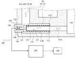
- FIG. 2A is a schematic partial cross-sectional view showing the detection device according to the first embodiment.
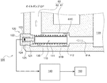
- FIG. 2B is a schematic partial cross-sectional view showing the detection device according to the first embodiment.
- FIG. 3 is a schematic functional block diagram of the electronic control unit according to the first embodiment.
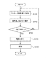
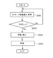
- FIG. 4 is a flowchart for explaining foreign object detection processing according to the first embodiment.
- FIG. 5 is a schematic functional block diagram of the electronic control unit according to the second embodiment.
- FIG. 6 is a flowchart for explaining the foreign object detection processing according to the second embodiment.
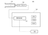
- FIG. 7 is a schematic functional block diagram of an electronic control unit according to another embodiment.
- FIG. 1 is a schematic longitudinal sectional view of a power transmission device 10 including a detection device 100 according to the first embodiment.
- the power transmission device 10 is a final drive device that is mounted on a rear two-axis drive vehicle including two drive shafts (a rear front shaft and a rear rear shaft) as rear shafts, for example.
- the vehicle may be any of a rear single-axis drive vehicle, a front wheel drive vehicle, a four wheel drive vehicle, and the like.
- the power transmission device 10 is not limited to the final drive device, and may be another power transmission device such as a transfer device or a transmission.
- the final drive device 10 includes a housing 11. In the bottom portion 11A of the housing 11, lubricating oil (a schematic liquid level OL is indicated by a broken line in the drawing) as an example of a fluid is stored.
- the final drive device 10 includes an input shaft 21, an output shaft 22, a drive pinion 42, and a gear mechanism 30.
- the input shaft 21 is rotatably supported by the housing 11 via a bearing 24.
- the input shaft 21 is connected to an output end of a propeller shaft to which driving force is transmitted from a transmission (not shown) or the like.
- the output shaft 22 is disposed coaxially with the input shaft 21 and is rotatably supported by the housing 11 via bearings 25 and 26.
- the output shaft 22 is connected to an input end of a propeller shaft that transmits a driving force to a rear rear shaft (not shown).
- the drive pinion 42 is disposed in parallel with the input shaft 21 in the housing 11, and is rotatably supported by the housing 11 via bearings 51 and 52.
- a drive pinion gear 42A is provided at one end of the drive pinion 42, and a ring gear 43 is engaged with the drive pinion gear 42A.
- the ring gear 43 is fixed to a differential cage (not shown) constituting a part of the rear front differential mechanism 44.
- the front / rear differential mechanism 44 includes a differential cage, a side gear, a differential pinion gear, a spider, and the like (not shown), and differentials are applied to the left and right drive shafts 15 and 16 (the right drive shaft 16 is not shown). The driving force is transmitted while allowing.
- the gear mechanism 30 transmits the driving force transmitted to the input shaft 21 to the output shaft 22 and the drive pinion 42 while allowing differential.
- the gear mechanism 30 includes a gear 31, a spider 32, a pair of pinion gears 33, a side gear 34, and a cage 35.
- the gear 31 is provided to be rotatable relative to the input shaft 21 and meshes with a gear 53 fixed to the drive pinion 42.
- the side gear 31 ⁇ / b> A of the gear 31 meshes with a pair of pinion gears 33.
- the side gear 34 is fixed to the output shaft 22 so as to be integrally rotatable, and meshes with a pair of pinion gears 33.
- the pair of pinion gears 33 are rotatably inserted into the spider 32, respectively.
- the spider 32 is fixed to a cage 35 provided on the input shaft 21 so as to be integrally rotatable.
- An oil pump OP that pumps up the lubricating oil stored in the bottom 11A of the housing 11 and pumps it is provided on the side of the housing 11.
- the oil pump OP is, for example, a gear pump or a trochoid pump, and is driven by power transmitted from the drive pinion 42.
- a downstream oil passage 60 is provided that allows communication between the bottom 11 ⁇ / b> A for storing lubricating oil and the suction port of the oil pump OP. Furthermore, an upstream oil passage 68 is provided inside the housing 11 to allow the discharge port of the oil pump OP and the axial oil passage 21A formed in the input shaft 21 to communicate with each other. When the oil pump OP is driven, the lubricating oil in the bottom portion 11 ⁇ / b> A is pumped up via the downstream oil passage 60 and is pumped to the upstream oil passage 68.
- the lubricating oil pumped to the upstream oil passage 68 is supplied to lubricating elements such as bearings via the axial oil passage 21A in the input shaft 21 and the plurality of radial oil passages 21B, and returned to the bottom 11A. It comes to circulate by.
- the detection device 100 is provided in the downstream oil passage 60. Hereinafter, details of the detection apparatus 100 will be described.
- the detection device 100 includes a strainer 110 (collecting unit), a stroke sensor 120 (detecting unit), a spring 130 (biasing unit), an electronic control unit 140 (detecting unit), an alarm, and the like.
- Device (alarm unit) 150 the strainer 110, a part of the stroke sensor 120, and the spring 130 are disposed in the downstream oil passage 60.
- the downstream oil passage 60 is bent in a substantially L shape, and extends in the lateral direction from the bottom 11A of the housing 11 in the lateral direction. And a longitudinal flow path 62 extending in the vertical direction. Further, the lateral flow channel 61 has an upstream small diameter flow channel portion 61A and a downstream large diameter flow channel portion 61B, and between these small diameter flow channel portion 61A and the large diameter flow channel portion 61B. An annular step surface 61C is formed.
- the strainer 110 is a mesh member that can pass through the lubricating oil and collect foreign substances contained in the lubricating oil (for example, iron powder and broken pieces generated by gear wear; hereinafter simply referred to as foreign substances). It has the strainer main-body part 111 (collection member) formed in the bottom cylinder shape.
- the cylinder shaft length of the strainer body 111 is formed shorter than the channel shaft length of the large-diameter channel portion 61B.
- the strainer body 111 is accommodated in the large-diameter channel 61B so as to be movable in the flow direction of the lubricating oil.
- an annular flange portion 112 that is bent at a substantially right angle toward the outer side in the radial direction is provided at the opening peripheral edge of the strainer main body portion 111.
- the inner diameters of the flange portion 112 and the strainer main body portion 111 are preferably formed to be substantially the same as the channel diameter of the small-diameter channel portion 61A. Moreover, the outer diameter of the flange part 112 is formed smaller than the flow path diameter of the large diameter flow path part 61B. The flange portion 112 is seated in pressure contact with the step surface 61 ⁇ / b> C by the urging force of the spring 130.
- the stroke sensor 120 includes a shaft 121 that is in contact with the outer surface of the bottom of the strainer body 111, a bottomed cylindrical casing 122 that supports the shaft 121 so that the stroke can be moved, and a return spring 123 that returns the shaft 121 to the origin position. (Biasing section) and a detection element section 124 that detects the stroke movement amount S of the shaft 121 corresponding to the movement amount of the strainer 110.
- the stroke movement amount S detected by the detection element unit 124 is input to the electronic control unit 140 that is electrically connected.
- the stroke sensor 120 screwes a male screw portion (not shown) formed on the outer periphery of the casing 122 with a female screw portion (not shown) formed on the inner periphery of the through hole 125 of the housing 11.
- the housing 11 is detachably attached. By removing the stroke sensor 120 from the housing 11, the strainer 110 can be periodically replaced (including reuse).
- the spring 130 has one end seated on the flange portion 112 and the other end seated on the cylinder end surface of the casing 122, and is held in a compressed state between the flange portion 112 and the casing 122.
- the strainer 110 When the amount of foreign matter in the lubricating oil is small (or almost zero), the amount of foreign matter (clogging degree) collected on the inner cylinder surface of the strainer body 111 is small, and the strainer body 111 is The flow resistance of the passing lubricating oil is small.
- the strainer 110 is held in a state where the flange portion 112 is seated on the stepped surface 61C by the biasing force of the spring 130, and the shaft 121 of the stroke sensor 120 is also held at the substantially origin position. The That is, the stroke movement amount S of the shaft 121 detected by the stroke sensor 120 is substantially zero.
- the stroke movement amount S of the shaft 121 detected by the stroke sensor 120 gradually increases in accordance with the movement of the strainer 110.
- the amount of foreign matter mixed in the lubricating oil increases rapidly, and the flow resistance of the lubricating oil passing through the strainer main body 111 increases rapidly with this, so that the shaft 121 and the strainer.
- the stroke movement amount S of 110 increases remarkably.
- such a change in the stroke movement amount S of the strainer 110 according to the accumulation of the foreign matter is used to detect foreign matter contamination in the lubricating oil.
- details of the foreign object detection processing by the electronic control unit 140 will be described.
- FIG. 3 is a schematic functional block diagram of the electronic control unit 140 according to the present embodiment.
- the electronic control unit 140 performs various controls of the vehicle, and includes a known CPU, ROM, RAM, input port, output port, and the like.
- the electronic control unit 140 includes a foreign matter contamination amount estimation unit 141 and an abnormality diagnosis unit 142 as some functional elements. Each of these functional elements will be described as being included in the electronic control unit 140 that is an integral piece of hardware, but any of these can be provided in separate hardware.
- the foreign matter contamination amount estimation unit 141 estimates the foreign matter contamination amount AM in the lubricating oil based on the stroke movement amount S of the strainer 110.
- the memory of the electronic control unit 140 stores a map M that defines the relationship between the stroke movement amount S of the strainer 110 and the foreign matter mixing amount AM in the lubricating oil, which has been created in advance through experiments or the like.
- the foreign matter mixing amount AM is set so as to increase rapidly as the stroke movement amount S increases.
- the foreign material contamination amount estimation unit 141 estimates the foreign material contamination amount AM by referring to the map M based on the stroke movement amount S input from the stroke sensor 120.
- the estimation method of the foreign matter mixing amount AM is not limited to the map M, and may be calculated from a model formula that includes the stroke movement amount S as an input value.
- the abnormality diagnosis unit 142 performs an abnormality diagnosis as to whether or not the final drive device 10 has a sign of failure due to gear breakage or the like, based on the foreign matter contamination amount AM estimated by the foreign matter contamination amount estimation unit 141.
- the memory of the electronic control unit 140 stores a foreign matter upper limit mixing amount threshold AM_Max that can cause a failure in the final drive device 10 obtained in advance through experiments or the like.
- the abnormality diagnosis unit 142 diagnoses that the final drive device 10 has a sign of a failure, and notifies the alarm device 150 An instruction signal for alarming is output.
- the alarm device 150 may be either a speaker that performs an alarm by sound or a display device that performs an alarm by display.
- step S100 the stroke movement amount S of the strainer 110 is acquired by the stroke sensor 120, and in step S110, the foreign matter mixture amount AM is estimated based on the acquired stroke movement amount S.
- step S120 it is determined whether or not the foreign matter mixing amount AM has reached the upper limit mixing amount threshold value AM_Max .
- the present control proceeds to step S130.
- the foreign matter mixing amount AM is less than the upper limit mixing amount threshold value AM_Max (No)
- the control returns to the process of step S100.
- step S130 an alarm is executed by the alarm device 150.
- step S140 the alarm is canceled.
- the alarm may be released after a certain period of time in order to prevent annoying alarm sound for a long time. Further, when the warning is given by display, it may be canceled by the operator when the vehicle is maintained at a maintenance factory or the like.
- the control is thereafter terminated.
- the foreign matter contamination amount AM in the lubricating oil is estimated from the stroke movement amount S of the strainer 110 that collects the foreign matter in the lubricating oil, and the estimated foreign matter contamination amount AM is the upper limit.
- the mixing amount threshold value AM_Max is reached, the final drive apparatus 10 is diagnosed as having a sign of a failure occurrence, and an alarm is issued. Accordingly, it is possible to appropriately notify the driver of an appropriate maintenance time before the final drive device 10 breaks down, and it is possible to prevent a road failure of the vehicle.
- the degree of progress of foreign matter contamination in the lubricating oil changes according to the driving state of the vehicle, such as the driving frequency of the vehicle and the magnitude of the input load on the gear, so the maintenance time is uniformly set based on the travel distance etc.
- the alarm is performed based on the foreign matter mixing amount AM estimated in real time, it is possible to effectively cope with such a change in the operation state and the like, and the failure of the final drive device 10 Predictive signs can be detected reliably.
- FIG. 5 is a schematic functional block diagram showing the electronic control unit 140 of the detection apparatus 100 according to the second embodiment.
- the detection apparatus 100 according to the second embodiment is obtained by omitting the foreign matter contamination amount estimation unit 141 from the electronic control unit 140 according to the first embodiment.
- the detection apparatus 100 which concerns on 2nd embodiment is provided in the power transmission device 10 similarly to 1st embodiment.
- the electronic control unit 140 of the second embodiment has an upper limit on the stroke amount of the strainer 110 corresponding to the amount of foreign matter mixed in the lubricating oil that may cause a failure in the final drive device 10 obtained in advance through experiments or the like. It is stored as a stroke amount threshold value S_Max .
- the abnormality diagnosis unit 142 diagnoses that the final drive device 10 has a sign of failure and issues an alarm to the alarm device 150. An instruction signal is output.
- the stroke movement amount S of the strainer 110 is acquired by the stroke sensor 120 in step S200 as shown in the flowchart of FIG. 6, and the stroke movement amount is acquired in step S210. It is determined whether or not S has reached the upper limit stroke amount threshold value S_Max . If the determination is affirmative, as in the first embodiment, the process proceeds to step S220, an alarm is executed, the alarm is canceled in step S230, and the present control ends.
- the detection device 100 of the second embodiment by comparing the stroke movement amount S of the strainer 110 and the upper limit stroke amount threshold value S_Max , a failure sign of the final drive device 10 is effectively detected. It becomes possible, and there can exist an effect similar to 1st embodiment.
- the stroke sensor 120 is used.
- the ON / OFF sensor 160 that switches from OFF to ON (or from ON to OFF) as the strainer 110 moves is moved. It may be used.
- an alarm may be provided when the ON / OFF sensor 160 is switched from OFF to ON (or from ON to OFF) by the stroke movement of the strainer 110.
- the spring 130 is not essential, and the spring 130 may be omitted if the return spring 123 with a built-in sensor has a certain reaction force.
- strainer 110 has been described as being provided in the downstream oil passage 60, it can also be disposed in another oil passage such as the upstream oil passage 68 or the like.
- the scope of application of the present embodiment is not limited to the power transmission device such as the final drive device 10, the transfer device, and the transmission, and any device including a gear case filled with lubricating oil circulates the lubricating oil such as an engine.
- the present invention can also be widely applied to other devices in which fluid other than lubricating oil circulates.
- the detection device of the present disclosure is useful in that it effectively detects foreign matter contamination in the fluid.
Landscapes
- Engineering & Computer Science (AREA)
- General Engineering & Computer Science (AREA)
- Mechanical Engineering (AREA)
- Chemical & Material Sciences (AREA)
- Chemical Kinetics & Catalysis (AREA)
- Quality & Reliability (AREA)
- General Details Of Gearings (AREA)
- Control Of Transmission Device (AREA)
Abstract
検出装置は、潤滑油が流通する流路内に設けられると共に、少なくともその一部に潤滑油を通過させて潤滑油中の異物を捕集する捕集部材を含み、捕集部材の異物堆積に伴い潤滑油の流通方向に移動されるストレーナと、ストレーナの流通方向への移動を検知するストロークセンサと、ストロークセンサにより検知されるストレーナの移動に基づいて、潤滑油中の異物混入を検出する検出部とを備える。
Description
本開示は、潤滑油等の流体中の異物混入を検出する検出装置に関する。
一般的に、車両には、ファイナルドライブ装置やトランスファ装置、トランスミッション等の動力伝達装置が搭載されている。これらの動力伝達装置においては、ハウジング内に、ギヤやベアリング等を潤滑する潤滑油が封入され、循環されている。
動力伝達装置においては、ギヤ等が摩耗するので、摩耗により生じた金属粉や破損片等の異物が潤滑油に混入する。このような異物が潤滑油に混入すると、ギヤやベアリング、オイルシール等に損傷を与えてしまい、これらの寿命を低下させてしまう虞がある。
例えば、特許文献1には、ファイナルドライブ装置の潤滑油中に混入している金属粉等をハウジング内に配置した磁石に吸着させることにより、潤滑油中の異物の除去を図る技術が開示されている。
しかし、特許文献1に記載の上記技術のように、磁石による金属粉の吸着のみでは、特に非磁性体等の異物を除去することができず、潤滑油中の異物混入を十分に防止できない可能性がある。潤滑油中の異物混入量が過多となり、ギヤ等に破損が生じると、ファイナルドライブ装置が動力伝達不能な状態になることで、車両の路上故障を引き起こす虞がある。このため、潤滑油中の異物混入を効果的に検出し、故障発生の前兆を運転者に適宜に知らせることにより、車両の路上故障を未然に防ぐことが望まれる。
本開示の目的は、流体中の異物混入を効果的に検出可能な検出装置を提供することである。
本開示の一態様に係る検出装置は、流体が流通する流路内に設けられると共に、少なくともその一部に前記流体を通過させて該流体中の異物を捕集する捕集部材を含み、該捕集部材の異物堆積に伴い前記流体の流通方向に移動される捕集部と、前記捕集部の前記流通方向への移動を検知する検知部と、前記検知部により検知される前記捕集部の移動に基づいて、前記流体中の異物混入を検出する検出部と、を備える。
また、前記検出部により検出される異物混入に基づいて警報を行う警報部をさらに備えることが好ましい。
また、前記検知部は、前記捕集部の移動量を取得するストロークセンサであり、前記検出部は、前記ストロークセンサにより取得される前記移動量に基づいて、前記流体中の異物混入量を推定すると共に、該異物混入量が所定の上限閾値に達すると、前記警報部に警報を行わせることが好ましい。
また、前記検知部は、前記捕集部の移動量を取得するストロークセンサであり、前記検出部は、前記ストロークセンサにより取得される前記移動量が所定の上限閾値に達すると、前記警報部に警報を行わせることが好ましい。
また、前記検知部は、前記捕集部の移動に伴いOFFからON又は、ONからOFFに切り替えられるON/OFFセンサであり、前記検出部は、前記ON/OFFセンサがOFFからON又は、ONからOFFに切り替わると、前記警報部に警報を行わせることが好ましい。
また、前記捕集部を前記流通方向とは反対方向に付勢する付勢部をさらに備え、前記捕集部は、前記捕集部材の異物堆積に伴い前記付勢部の付勢力に抗して前記流通方向へ移動されることが好ましい。
また、前記捕集部は、前記流体中の異物を捕集可能なメッシュ部材で有底筒体状に形成されると共に、その筒体開口側を前記流通方向の上流側に向けられたストレーナ部材であってもよい。
また、前記流体は、車両用の動力伝達装置のハウジング内を循環する潤滑油であり、前記流路は、前記ハウジングに形成されて前記潤滑油を流通させる潤滑油路であってもよい。
本開示によれば、流体中の異物混入を効果的に検出することができる。
以下、添付図面に基づいて、実施形態に係る検出装置を説明する。同一の部品には同一の符号を付してあり、それらの名称および機能も同じである。したがって、それらについての詳細な説明は繰返さない。
[第一実施形態]
図1は、第一実施形態に係る検出装置100を備えた動力伝達装置10の模式的な縦断面図である。同図に示すように、動力伝達装置10は、例えば、後軸として二本の駆動軸(後前軸及び後後軸)を備えた後二軸駆動車両に搭載されるファイナルドライブ装置である。なお、車両は、後一軸駆動車両、前輪駆動車両、四輪駆動車両等の何れであってもよい。また、動力伝達装置10は、ファイナルドライブ装置に限定されず、トランスファ装置やトランスミッション等の他の動力伝達装置であってもよい。
図1は、第一実施形態に係る検出装置100を備えた動力伝達装置10の模式的な縦断面図である。同図に示すように、動力伝達装置10は、例えば、後軸として二本の駆動軸(後前軸及び後後軸)を備えた後二軸駆動車両に搭載されるファイナルドライブ装置である。なお、車両は、後一軸駆動車両、前輪駆動車両、四輪駆動車両等の何れであってもよい。また、動力伝達装置10は、ファイナルドライブ装置に限定されず、トランスファ装置やトランスミッション等の他の動力伝達装置であってもよい。
ファイナルドライブ装置10は、ハウジング11を備えている。ハウジング11の底部11Aには、流体の一例としての潤滑油(図中に模式的な液面レベルOLを破線で示す)が貯留されている。また、ファイナルドライブ装置10は、入力軸21と、出力軸22と、ドライブピニオン42と、ギヤ機構30とを備えている。
入力軸21は、ベアリング24を介してハウジング11に回転可能に軸支されている。入力軸21には、図示しないトランスミッション等から駆動力が伝達されるプロペラシャフトの出力端が接続されている。
出力軸22は、入力軸21と同軸上に配置されており、ベアリング25,26を介してハウジング11に回転可能に軸支されている。出力軸22には、何れも不図示の後後軸に駆動力を伝達するプロペラシャフトの入力端が接続されている。
ドライブピニオン42は、ハウジング11内に入力軸21と平行に配置されており、ベアリング51,52を介してハウジング11に回転可能に軸支されている。ドライブピニオン42の一端にはドライブピニオンギヤ42Aが設けられ、このドライブピニオンギヤ42Aにはリングギヤ43が噛合されている。また、リングギヤ43は、後前差動機構44の一部を構成する不図示のデフケージに固定されている。後前差動機構44は、何れも図示を省略するデフケージ、サイドギヤ、デフピニオンギヤ及び、スパイダ等を備えており、左右駆動軸15,16(右駆動軸16は図示を省略)に、差動を許容しつつ駆動力を伝達するように構成されている。
ギヤ機構30は、入力軸21に伝達された駆動力を、差動を許容しつつ、出力軸22及びドライブピニオン42に伝達する。具体的には、ギヤ機構30は、ギヤ31と、スパイダ32と、一対のピニオンギヤ33と、サイドギヤ34と、ケージ35とを備えている。ギヤ31は、入力軸21に相対回転可能に設けられており、ドライブピニオン42に固定されたギヤ53と噛合されている。また、ギヤ31のサイドギヤ31Aは、1対のピニオンギヤ33と噛合している。サイドギヤ34は、出力軸22に一体回転可能に固定されており、1対のピニオンギヤ33と噛合している。一対のピニオンギヤ33は、スパイダ32にそれぞれ回転可能に挿通されている。スパイダ32は、入力軸21に一体回転可能に設けられたケージ35に固定されている。
ハウジング11の側部には、ハウジング11の底部11Aに貯溜されている潤滑油を汲み上げて圧送するオイルポンプOPが設けられている。オイルポンプOPは、例えば、ギヤポンプやトロコイドポンプであって、ドライブピニオン42から伝達される動力で駆動する。
ハウジング11の内部には、潤滑油を貯留する底部11AとオイルポンプOPの吸入口とを連通させる下流油路60が設けられている。さらに、ハウジング11の内部には、オイルポンプOPの吐出口と入力軸21内に形成された軸方向油路21Aとを連通させる上流油路68が設けられている。オイルポンプOPが駆動すると、底部11A内の潤滑油は下流油路60を経由して汲み上げられ、上流油路68に圧送される。上流油路68に圧送された潤滑油は、入力軸21内の軸方向油路21A及び、複数の径方向油路21Bを介して各ベアリング等の潤滑要素に供給され、底部11Aに戻されることにより循環するようになっている。
本実施形態において、検出装置100は、下流油路60に設けられている。以下、検出装置100の詳細について説明する。
図2A及び図2Bは、本実施形態に係る検出装置100を示す模式的な部分断面図である。同図に示すように、検出装置100は、ストレーナ110(捕集部)と、ストロークセンサ120(検知部)と、スプリング130(付勢部)と、電子制御ユニット140(検出部)と、警報器(警報部)150とを備えている。これら構成要素のうち、ストレーナ110、ストロークセンサ120の一部及び、スプリング130は、下流油路60内に配置されている。
下流油路60は、略L字状に屈曲形成されており、ハウジング11の底部11Aから横方向に延びる横方向流路61と、横方向流路61の下流端からオイルポンプOP側に縦方向に延びる縦方向流路62とを有する。また、横方向流路61は、上流側の小径流路部61Aと、下流側の大径流路部61Bとを有しており、これら小径流路部61Aと大径流路部61Bとの間には円環状の段差面61Cが形成されている。
ストレーナ110は、潤滑油を通過させて潤滑油中に含まれる異物(例えば、ギヤの摩耗により生じた鉄粉や破損片等:以下、単に異物と称する)を捕集可能なメッシュ部材で略有底筒体状に形成されたストレーナ本体部111(捕集部材)を有する。ストレーナ本体部111の筒軸長さは、大径流路部61Bの流路軸長さよりも短く形成されている。ストレーナ本体部111は、大径流路部61B内に潤滑油の流通方向に移動可能に収容されている。また、ストレーナ本体部111の開口周縁には、径方向外方に向けて略直角に折れ曲がる円環状のフランジ部112が設けられている。
フランジ部112及びストレーナ本体部111の内径は、好ましくは、小径流路部61Aの流路径と略同径に形成されている。また、フランジ部112の外径は、大径流路部61Bの流路径よりも小径に形成されている。フランジ部112は、スプリング130の付勢力によって段差面61Cに圧接状態で着座されている。
ストロークセンサ120は、ストレーナ本体部111の筒底部外側面に当接するシャフト121と、シャフト121をストローク移動可能に支持する有底筒状のケーシング122と、シャフト121を原点位置に復帰させるリターンバネ123(付勢部)と、ストレーナ110の移動量に相当するシャフト121のストローク移動量Sを検出する検出素子部124とを備えている。検出素子部124によって検出されるストローク移動量Sは、電気的に接続された電子制御ユニット140に入力される。
本実施形態において、ストロークセンサ120は、ケーシング122の外周に形成された不図示の雄ネジ部を、ハウジング11の貫通孔125の内周に形成された不図示の雌ネジ部と螺合させることにより、ハウジング11に着脱可能に取り付けられている。ストロークセンサ120をハウジング11から取り外すことにより、ストレーナ110を定期交換(再利用を含む)できるように構成されている。
スプリング130は、一端側をフランジ部112に着座させると共に、他端側をケーシング122の筒端面に着座させており、これらフランジ部112とケーシング122との間に圧縮状態で保持されている。
潤滑油中の異物混入量が少ない状態(或は、略ゼロ)のときは、ストレーナ本体部111の内筒面に捕集される異物の量(目詰まり度合い)も少なく、ストレーナ本体部111を通過する潤滑油の流通抵抗は小さい。この場合は、図2Aに示すように、ストレーナ110は、スプリング130の付勢力によってフランジ部112を段差面61Cに着座させた状態に保持され、ストロークセンサ120のシャフト121も略原点位置に保持される。すなわち、ストロークセンサ120により検出されるシャフト121のストローク移動量Sは略ゼロとなる。
その後、潤滑油中の異物混入量が増加し、ストレーナ本体部111の内筒面に異物が堆積し始めると、これに伴い、ストレーナ本体部111の目詰まり度合いが増加することで、ストレーナ本体部111を通過する潤滑油の流通抵抗は次第に大きくなる。すると、図2Bに示すように、ストレーナ110は、スプリング130の付勢力に抗して潤滑油の流れ方向にストローク移動する。ストレーナ110がストローク移動すると、小径流路部61Aを流れる潤滑油は、フランジ部112と段差面61Cとの隙間を通って大径流路部61B内を流れるようになる。
この際、ストロークセンサ120により検出されるシャフト121のストローク移動量Sは、ストレーナ110の移動に応じて次第に増加する。特に、ギヤ等が破損する故障発生の直前になると、潤滑油中の異物混入量が急増し、これに伴いストレーナ本体部111を通過する潤滑油の流通抵抗も急増することで、シャフト121及びストレーナ110のストローク移動量Sは著しく増加する。本実施形態では、このような、異物堆積に応じたストレーナ110のストローク移動量Sの変化を利用して、潤滑油中の異物混入を検出する。以下、電子制御ユニット140による異物検出処理の詳細を説明する。
図3は、本実施形態に係る電子制御ユニット140の模式的な機能ブロック図である。電子制御ユニット140は、車両の各種制御を行うもので、公知のCPUやROM、RAM、入力ポート、出力ポート等を備えて構成されている。また、電子制御ユニット140は、異物混入量推定部141と、異常診断部142とを一部の機能要素として有している。これら各機能要素は、一体のハードウェアである電子制御ユニット140に含まれるものとして説明するが、これらの何れかを別体のハードウェアに設けることもできる。
異物混入量推定部141は、ストレーナ110のストローク移動量Sに基づいて、潤滑油中の異物混入量AMを推定する。具体的には、電子制御ユニット140のメモリには、予め実験等により作成したストレーナ110のストローク移動量Sと潤滑油中の異物混入量AMとの関係を定めたマップMが格納されている。マップMにおいて、異物混入量AMは、ストローク移動量Sが長くなるに従い急激に増大するように設定されている。異物混入量推定部141は、ストロークセンサ120から入力されるストローク移動量Sに基づいてマップMを参照することにより、異物混入量AMを推定する。なお、異物混入量AMの推定手法はマップMに限定されず、ストローク移動量Sを入力値として含むモデル式等から演算してもよい。
異常診断部142は、異物混入量推定部141により推定される異物混入量AMに基づいて、ファイナルドライブ装置10にギヤ破損等による故障発生の前兆があるか否かの異常診断を行う。具体的には、電子制御ユニット140のメモリには、予め実験等により取得したファイナルドライブ装置10に故障を発生させ得る異物の上限混入量閾値AM_Maxが記憶されている。異常診断部142は、異物混入量推定部141から入力される異物混入量AMが上限混入量閾値AM_Maxに達すると、ファイナルドライブ装置10に故障発生の前兆があると診断し、警報器150に警報を行わせる指示信号を出力する。警報器150は、音声により警報を行うスピーカ、又は、表示により警報を行う表示器の何れであってもよい。
次に、図4に基づいて、本実施形態に係る異物検出処理のフローを説明する。
ステップS100では、ストロークセンサ120によりストレーナ110のストローク移動量Sを取得し、ステップS110では、取得したストローク移動量Sに基づいて異物混入量AMを推定する。
ステップS120では、異物混入量AMが上限混入量閾値AM_Maxに達しているか否かを判定する。異物混入量AMが上限混入量閾値AM_Maxに達している場合(肯定)、本制御はステップS130の処理に進む。一方、異物混入量AMが上限混入量閾値AM_Max未満の場合(否定)、本制御はステップS100の処理に戻る。
ステップS130では、警報器150により警報を実行する。次いで、ステップS140では、警報を解除する。警報の解除としては、例えば、警報が音により実行される場合には、警報音が長期に鳴る煩わしさを防止するために、一定時間経過後に警報を解除すればよい。また、警報が表示により行われる場合には、車両がメンテナンス工場等でメンテナンスされる際に、作業者により解除されるようにすればよい。ステップS140にて警報が解除されると、その後、本制御は終了する。
以上詳述した本実施形態によれば、潤滑油中の異物を捕集するストレーナ110のストローク移動量Sから潤滑油中の異物混入量AMを推定すると共に、推定される異物混入量AMが上限混入量閾値AM_Maxに達した場合には、ファイナルドライブ装置10に故障発生の前兆があると診断し、警報を行うように構成されている。これにより、運転者に対して、ファイナルドライブ装置10が故障する前段階にて、適切なメンテナンス時期を適宜に知らせることが可能となり、車両の路上故障を未然に防止することができる。
特に、潤滑油中の異物混入の進行度合いは、車両の運転頻度やギヤに対する入力負荷の大きさ等、車両の運転状態に応じて変化するため、メンテナンス時期を走行距離等に基づいて一律に設定するのみでは、ファイナルドライブ装置10の故障を未然に防止できない虞がある。本実施形態では、リアルタイムに推定される異物混入量AMに基づいて警報を行うため、このような運転状況等の変化に対しても効果的に対応することが可能となり、ファイナルドライブ装置10の故障前兆を確実に検知することができる。
[第二実施形態]
図5は、第二実施形態に係る検出装置100の電子制御ユニット140を示す模式的な機能ブロック図である。同図に示すように、第二実施形態の検出装置100は、第一実施形態の電子制御ユニット140から、異物混入量推定部141を省略したものである。なお、第二実施形態に係る検出装置100は、第一実施形態と同様に、動力伝達装置10に設けられる。
図5は、第二実施形態に係る検出装置100の電子制御ユニット140を示す模式的な機能ブロック図である。同図に示すように、第二実施形態の検出装置100は、第一実施形態の電子制御ユニット140から、異物混入量推定部141を省略したものである。なお、第二実施形態に係る検出装置100は、第一実施形態と同様に、動力伝達装置10に設けられる。
具体的には、第二実施形態の電子制御ユニット140には、予め実験等により取得したファイナルドライブ装置10に故障を発生させ得る潤滑油中の異物混入量に対応するストレーナ110のストローク量が上限ストローク量閾値S_Maxとして記憶されている。異常診断部142は、ストロークセンサ120から入力されるストローク移動量Sが上限ストローク量閾値S_Maxに達すると、ファイナルドライブ装置10に故障発生の前兆があると診断し、警報器150に警報を行わせる指示信号を出力する。
すなわち、第二実施形態に係る異物検出処理は、図6のフローチャートに示すように、ステップS200にて、ストロークセンサ120によりストレーナ110のストローク移動量Sを取得し、ステップS210にて、ストローク移動量Sが上限ストローク量閾値S_Maxに達しているか否かを判定する。肯定の場合は、第一実施形態と同様、ステップS220に進んで警報を実行し、ステップS230にて警報を解除して本制御は終了する。
このように、第二実施形態の検出装置100によれば、ストレーナ110のストローク移動量Sと上限ストローク量閾値S_Maxとを比較することで、ファイナルドライブ装置10の故障前兆を効果的に検知することが可能となり、第一実施形態と同様の作用効果を奏することができる。
なお、本開示は、上述の実施形態に限定されるものではなく、本開示の趣旨を逸脱しない範囲で、適宜に変形して実施することが可能である。
例えば、上記実施形態では、ストロークセンサ120を用いるものとして説明したが、図7に示すように、ストレーナ110のストローク移動に伴いOFFからON(又は、ONからOFF)に切り替わるON/OFFセンサ160を用いてもよい。ON/OFFセンサ160を用いる場合は、ストレーナ110のストローク移動によりON/OFFセンサ160がOFFからON(又は、ONからOFF)に切り替えられた際に、警報を行うように構成すればよい。
また、スプリング130は必須ではなく、センサ内蔵のリターンバネ123が一定の反力を有していれば、スプリング130を省略してもよい。
また、ストレーナ110は、下流油路60内に設けられるものとして説明したが、上流油路68等、ファイナルドライブ装置10の他の油路に配置することもできる。
また、本実施形態の適用範囲は、ファイナルドライブ装置10やトランスファ装置、トランスミッション等の動力伝達装置に限定されず、潤滑油を封入したギヤケースを備える装置であれば、例えばエンジン等、潤滑油が循環する装置、或は、潤滑油以外の流体が循環する他の装置類にも広く適用することが可能である。
本出願は、2018年3月19日付で出願された日本国特許出願(特願2018-051110)に基づくものであり、その内容はここに参照として取り込まれる。
本開示の検出装置は、流体中の異物混入を効果的に検出するといった点において有用である。
10 ファイナルドライブ装置(動力伝達装置)
11 ハウジング
60 下流油路
68 上流油路
100 検出装置
110 ストレーナ(捕集部)
111 ストレーナ本体部(捕集部材)
112 フランジ部
120 ストロークセンサ(検知部)
130 スプリング(付勢部)
140 電子制御ユニット(検出部)
150 警報器(警報部)
11 ハウジング
60 下流油路
68 上流油路
100 検出装置
110 ストレーナ(捕集部)
111 ストレーナ本体部(捕集部材)
112 フランジ部
120 ストロークセンサ(検知部)
130 スプリング(付勢部)
140 電子制御ユニット(検出部)
150 警報器(警報部)
Claims (8)
- 流体が流通する流路内に設けられると共に、少なくともその一部に前記流体を通過させて該流体中の異物を捕集する捕集部材を含み、該捕集部材の異物堆積に伴い前記流体の流通方向に移動される捕集部と、
前記捕集部の前記流通方向への移動を検知する検知部と、
前記検知部により検知される前記捕集部の移動に基づいて、前記流体中の異物混入を検出する検出部と、を備える
ことを特徴とする検出装置。 - 前記検出部により検出される異物混入に基づいて警報を行う警報部をさらに備える
請求項1に記載の検出装置。 - 前記検知部は、前記捕集部の移動量を取得するストロークセンサであり、
前記検出部は、前記ストロークセンサにより取得される前記移動量に基づいて、前記流体中の異物混入量を推定すると共に、該異物混入量が所定の上限閾値に達すると、前記警報部に警報を行わせる
請求項2に記載の検出装置。 - 前記検知部は、前記捕集部の移動量を取得するストロークセンサであり、
前記検出部は、前記ストロークセンサにより取得される前記移動量が所定の上限閾値に達すると、前記警報部に警報を行わせる
請求項2に記載の検出装置。 - 前記検知部は、前記捕集部の移動に伴いOFFからON又は、ONからOFFに切り替えられるON/OFFセンサであり、
前記検出部は、前記ON/OFFセンサがOFFからON又は、ONからOFFに切り替わると、前記警報部に警報を行わせる
請求項2に記載の検出装置。 - 前記捕集部を前記流通方向とは反対方向に付勢する付勢部をさらに備え、
前記捕集部は、前記捕集部材の異物堆積に伴い前記付勢部の付勢力に抗して前記流通方向へ移動される
請求項1から5の何れか一項に記載の検出装置。 - 前記捕集部は、前記流体中の異物を捕集可能なメッシュ部材で有底筒体状に形成されると共に、その筒体開口側を前記流通方向の上流側に向けられたストレーナ部材である
請求項1から6の何れか一項に記載の検出装置。 - 前記流体は、車両用の動力伝達装置のハウジング内を循環する潤滑油であり、
前記流路は、前記ハウジングに形成されて前記潤滑油を流通させる潤滑油路である
請求項1から7の何れか一項に記載の検出装置。
Priority Applications (3)
| Application Number | Priority Date | Filing Date | Title |
|---|---|---|---|
| DE112019001391.2T DE112019001391B4 (de) | 2018-03-19 | 2019-03-15 | Erfassungsvorrichtung |
| CN201980020561.9A CN111886426A (zh) | 2018-03-19 | 2019-03-15 | 检测装置 |
| US16/982,515 US20210001252A1 (en) | 2018-03-19 | 2019-03-15 | Detection device |
Applications Claiming Priority (2)
| Application Number | Priority Date | Filing Date | Title |
|---|---|---|---|
| JP2018051110A JP2019163794A (ja) | 2018-03-19 | 2018-03-19 | 検出装置 |
| JP2018-051110 | 2018-03-19 |
Publications (1)
| Publication Number | Publication Date |
|---|---|
| WO2019181769A1 true WO2019181769A1 (ja) | 2019-09-26 |
Family
ID=67987765
Family Applications (1)
| Application Number | Title | Priority Date | Filing Date |
|---|---|---|---|
| PCT/JP2019/010782 Ceased WO2019181769A1 (ja) | 2018-03-19 | 2019-03-15 | 検出装置 |
Country Status (5)
| Country | Link |
|---|---|
| US (1) | US20210001252A1 (ja) |
| JP (1) | JP2019163794A (ja) |
| CN (1) | CN111886426A (ja) |
| DE (1) | DE112019001391B4 (ja) |
| WO (1) | WO2019181769A1 (ja) |
Families Citing this family (2)
| Publication number | Priority date | Publication date | Assignee | Title |
|---|---|---|---|---|
| DE102020216241B4 (de) | 2020-12-18 | 2022-08-25 | Zf Friedrichshafen Ag | Saugfilteranordnung für ein Getriebe eines Fahrzeuges |
| JP7835604B2 (ja) * | 2022-04-04 | 2026-03-25 | 株式会社小松製作所 | 異物認識システム |
Citations (3)
| Publication number | Priority date | Publication date | Assignee | Title |
|---|---|---|---|---|
| JPH0385751U (ja) * | 1989-12-15 | 1991-08-29 | ||
| JPH061899U (ja) * | 1992-06-15 | 1994-01-14 | ジャトコ株式会社 | 自動変速機トルクコンバータの異常検出装置 |
| WO2017191852A1 (ja) * | 2017-06-16 | 2017-11-09 | 株式会社小松製作所 | フィルタ状態推定システムおよびフィルタ状態の推定方法 |
Family Cites Families (8)
| Publication number | Priority date | Publication date | Assignee | Title |
|---|---|---|---|---|
| US3323648A (en) * | 1964-11-12 | 1967-06-06 | Rosaen Filter Co | Filter device with electrically actuated indicating means |
| FR2161236A5 (en) * | 1971-11-18 | 1973-07-06 | Dba | Filter with automatic by-pass - actuated by excessive pressure drop and signalling blocked condition electrically |
| JPS57163003U (ja) * | 1981-04-08 | 1982-10-14 | ||
| JPH08312754A (ja) * | 1995-05-23 | 1996-11-26 | Tochigi Fuji Ind Co Ltd | デファレンシャル装置 |
| US6423215B1 (en) * | 2001-03-08 | 2002-07-23 | Myron Stein | Fluid filter unit with automatic clogged filter element bypass and ferrous indicator flag |
| JP2008151279A (ja) * | 2006-12-19 | 2008-07-03 | Denso Corp | 自動変速機の油圧制御装置 |
| JP5624006B2 (ja) * | 2011-10-05 | 2014-11-12 | 本田技研工業株式会社 | オイルフィルター |
| US20170340996A1 (en) * | 2015-02-13 | 2017-11-30 | Qualc, Inc. | Filter System and Vehicle State Monitoring Method |
-
2018
- 2018-03-19 JP JP2018051110A patent/JP2019163794A/ja active Pending
-
2019
- 2019-03-15 DE DE112019001391.2T patent/DE112019001391B4/de active Active
- 2019-03-15 US US16/982,515 patent/US20210001252A1/en not_active Abandoned
- 2019-03-15 WO PCT/JP2019/010782 patent/WO2019181769A1/ja not_active Ceased
- 2019-03-15 CN CN201980020561.9A patent/CN111886426A/zh not_active Withdrawn
Patent Citations (3)
| Publication number | Priority date | Publication date | Assignee | Title |
|---|---|---|---|---|
| JPH0385751U (ja) * | 1989-12-15 | 1991-08-29 | ||
| JPH061899U (ja) * | 1992-06-15 | 1994-01-14 | ジャトコ株式会社 | 自動変速機トルクコンバータの異常検出装置 |
| WO2017191852A1 (ja) * | 2017-06-16 | 2017-11-09 | 株式会社小松製作所 | フィルタ状態推定システムおよびフィルタ状態の推定方法 |
Also Published As
| Publication number | Publication date |
|---|---|
| DE112019001391B4 (de) | 2024-02-15 |
| JP2019163794A (ja) | 2019-09-26 |
| DE112019001391T5 (de) | 2020-12-03 |
| US20210001252A1 (en) | 2021-01-07 |
| CN111886426A (zh) | 2020-11-03 |
Similar Documents
| Publication | Publication Date | Title |
|---|---|---|
| JP5014358B2 (ja) | 走行減速機用潤滑油の冷却装置 | |
| US8147683B2 (en) | Portable lubricant filtration system and method | |
| JP7412890B2 (ja) | 油圧機器の検査装置、油圧機器の検査システム、作業車両および油圧機器の検査方法 | |
| JP2019163794A (ja) | 検出装置 | |
| CN201818769U (zh) | 工业传动装置 | |
| CN107110332A (zh) | 变速器 | |
| CN111173867B (zh) | 摩擦接合装置 | |
| US11480242B2 (en) | Fatigue damage degree estimation device and method | |
| US20200171510A1 (en) | Coolant processing deivce | |
| CN102667470A (zh) | 用于测量液压油、传动装置油和润滑油中的颗粒的设备 | |
| US10890244B2 (en) | Power transmission device | |
| JP2016070309A (ja) | 車両用変速機の潤滑構造 | |
| JP4968520B2 (ja) | 軸受装置 | |
| JP4841943B2 (ja) | 漏れ油排出装置 | |
| JP5173688B2 (ja) | 産業車両のフィルタ故障診断方法及び装置 | |
| US20140151966A1 (en) | Dual sealing arrangement for final drive gear box | |
| CN115042561B (zh) | 车辆的控制方法、装置、车辆及计算机可读存储介质 | |
| CN111828126B (zh) | 一种发动机油路结构及车辆 | |
| EP2643589B1 (en) | Pumps and pump-heads with separately removable field-serviceable portion | |
| CN120368031A (zh) | 新能源汽车动力总成的润滑系统 | |
| JP2010071301A (ja) | シール不良警報装置 | |
| CN113874701A (zh) | 借助气味传感器检测损坏 | |
| CN120367835A (zh) | 立式泵和用于其的润滑油泄漏收集及检测装置 | |
| JP2010077622A (ja) | オイルレベル検知機能を備えた建設機械における油圧モータ旋回ユニット | |
| JP2006104987A (ja) | ポンプ装置 |
Legal Events
| Date | Code | Title | Description |
|---|---|---|---|
| 121 | Ep: the epo has been informed by wipo that ep was designated in this application |
Ref document number: 19770751 Country of ref document: EP Kind code of ref document: A1 |
|
| 122 | Ep: pct application non-entry in european phase |
Ref document number: 19770751 Country of ref document: EP Kind code of ref document: A1 |