WO2019181718A1 - クラッチシステムにおける制御装置及びそれを備えたクラッチ制御装置 - Google Patents
クラッチシステムにおける制御装置及びそれを備えたクラッチ制御装置 Download PDFInfo
- Publication number
- WO2019181718A1 WO2019181718A1 PCT/JP2019/010492 JP2019010492W WO2019181718A1 WO 2019181718 A1 WO2019181718 A1 WO 2019181718A1 JP 2019010492 W JP2019010492 W JP 2019010492W WO 2019181718 A1 WO2019181718 A1 WO 2019181718A1
- Authority
- WO
- WIPO (PCT)
- Prior art keywords
- clutch
- control
- target value
- valve
- piston
- Prior art date
- Legal status (The legal status is an assumption and is not a legal conclusion. Google has not performed a legal analysis and makes no representation as to the accuracy of the status listed.)
- Ceased
Links
Images


Classifications
-
- B—PERFORMING OPERATIONS; TRANSPORTING
- B60—VEHICLES IN GENERAL
- B60K—ARRANGEMENT OR MOUNTING OF PROPULSION UNITS OR OF TRANSMISSIONS IN VEHICLES; ARRANGEMENT OR MOUNTING OF PLURAL DIVERSE PRIME-MOVERS IN VEHICLES; AUXILIARY DRIVES FOR VEHICLES; INSTRUMENTATION OR DASHBOARDS FOR VEHICLES; ARRANGEMENTS IN CONNECTION WITH COOLING, AIR INTAKE, GAS EXHAUST OR FUEL SUPPLY OF PROPULSION UNITS IN VEHICLES
- B60K23/00—Arrangement or mounting of control devices for vehicle transmissions, or parts thereof, not otherwise provided for
- B60K23/02—Arrangement or mounting of control devices for vehicle transmissions, or parts thereof, not otherwise provided for for main transmission clutches
-
- F—MECHANICAL ENGINEERING; LIGHTING; HEATING; WEAPONS; BLASTING
- F16—ENGINEERING ELEMENTS AND UNITS; GENERAL MEASURES FOR PRODUCING AND MAINTAINING EFFECTIVE FUNCTIONING OF MACHINES OR INSTALLATIONS; THERMAL INSULATION IN GENERAL
- F16D—COUPLINGS FOR TRANSMITTING ROTATION; CLUTCHES; BRAKES
- F16D25/00—Fluid-actuated clutches
- F16D25/06—Fluid-actuated clutches in which the fluid actuates a piston incorporated in, i.e. rotating with the clutch
- F16D25/062—Fluid-actuated clutches in which the fluid actuates a piston incorporated in, i.e. rotating with the clutch the clutch having friction surfaces
- F16D25/063—Fluid-actuated clutches in which the fluid actuates a piston incorporated in, i.e. rotating with the clutch the clutch having friction surfaces with clutch members exclusively moving axially
- F16D25/0635—Fluid-actuated clutches in which the fluid actuates a piston incorporated in, i.e. rotating with the clutch the clutch having friction surfaces with clutch members exclusively moving axially with flat friction surfaces, e.g. discs
-
- F—MECHANICAL ENGINEERING; LIGHTING; HEATING; WEAPONS; BLASTING
- F16—ENGINEERING ELEMENTS AND UNITS; GENERAL MEASURES FOR PRODUCING AND MAINTAINING EFFECTIVE FUNCTIONING OF MACHINES OR INSTALLATIONS; THERMAL INSULATION IN GENERAL
- F16D—COUPLINGS FOR TRANSMITTING ROTATION; CLUTCHES; BRAKES
- F16D25/00—Fluid-actuated clutches
- F16D25/12—Details not specific to one of the before-mentioned types
-
- F—MECHANICAL ENGINEERING; LIGHTING; HEATING; WEAPONS; BLASTING
- F16—ENGINEERING ELEMENTS AND UNITS; GENERAL MEASURES FOR PRODUCING AND MAINTAINING EFFECTIVE FUNCTIONING OF MACHINES OR INSTALLATIONS; THERMAL INSULATION IN GENERAL
- F16D—COUPLINGS FOR TRANSMITTING ROTATION; CLUTCHES; BRAKES
- F16D48/00—External control of clutches
- F16D48/02—Control by fluid pressure
Definitions
- the present disclosure relates to a control device in a clutch system configured to control connection / disconnection of a clutch device by controlling supply and discharge of a working fluid to / from a clutch actuator, and clutch control including the control device Relates to the device.
- Patent Document 1 discloses a clutch device in which connection / disconnection is controlled by controlling supply and discharge of a working fluid to and from a cylinder chamber (that is, a pressure chamber) of a clutch actuator.
- a return spring is provided between one end of the clutch disk and the mechanical automatic transmission so as to urge the clutch disk.
- the release fork is urged in the first direction as the piston of the clutch actuator moves, and as a result, the engagement of the clutch device against the urging force of the return spring.
- the connection is cut.
- the release fork is biased in the second direction opposite to the first direction by the biasing force of the return spring and the engagement of the clutch device is connected.
- some clutch devices as described above use a spring member having a hysteresis characteristic.
- a diaphragm spring when used in the clutch device as described above, when the engagement of the clutch device in the disengaged state is changed from the disengaged state to the contact state, the behavior of the diaphragm spring can affect the hysteresis. This may cause a delay in the initial operation of the piston as described above, and may cause a decrease in the response of the clutch device.
- an object of the technology of the present disclosure is to suppress the influence of hysteresis of an elastic member provided to exert a biasing force on the clutch member at the start of switching of connection / disconnection of the clutch device.
- the technology of the present disclosure is provided so as to adjust a biasing force of the elastic member to the clutch member, and a clutch device including an elastic member provided to bias the clutch member.
- a clutch provided with a piston member provided in the cylinder member so as to be able to act on the elastic member, and a pressure chamber provided in the cylinder member so that the piston member is movable in the cylinder member.
- a control device in a clutch system including an actuator and at least one adjustment valve provided for supplying and discharging a working fluid to and from the pressure chamber, and configured to perform an operation determination on the clutch device.
- the piston member based on a target value corresponding to a determination result of the clutch operation determination unit and the clutch operation determination unit;
- a valve control unit configured to control the at least one adjustment valve, and the valve control unit changes the position of the piston member at the time of determination by the clutch operation determination unit to the target value.
- the piston member is moved based on the position of the piston member at the time of the determination, the piston member is moved to the target value side so as to exceed the target value after overshoot control, and then the piston member is moved to the target value.
- a control device in a clutch system for controlling the at least one adjusting valve so as to perform control to move to a value side.
- the valve control unit may control the at least one adjustment valve so as to perform the control of moving the piston member to the target value side after performing the overshoot control.
- the technology of the present disclosure also provides a clutch control device including the control device and the at least one adjustment valve provided for supplying and discharging the working fluid to and from the pressure chamber.
- the clutch device since the above configuration is provided, it is possible to suppress the hysteresis phenomenon in the elastic member when the clutch device is in a state corresponding to the determination result of the clutch operation determination unit, and thus the clutch device is It is possible to suppress the influence of the hysteresis of the elastic member at the start of switching.
- FIG. 1 is a schematic configuration diagram of a clutch system to which a control device according to an embodiment of the present disclosure is applied.
- FIG. 2 is a functional configuration diagram of a control device in the clutch system of FIG.
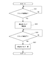
- FIG. 3 is a flowchart of clutch disengagement process control in the control device of FIG.
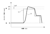
- FIG. 4 is a graph schematically showing an example of a change in the stroke of the piston of the clutch actuator by the clutch process control in the control device of FIG.
- FIG. 5 is a flowchart of clutch engagement processing control in the control device of FIG.
- FIG. 1 is a schematic configuration diagram of a clutch system 1 including a control device in a clutch system (hereinafter simply referred to as “control device”) according to an embodiment of the technology of the present disclosure.
- the clutch system 1 includes a clutch device 10, a clutch actuator 20, a clutch control device 2, and a stroke sensor 18.
- the clutch device 10 includes a flywheel 12, a clutch disk 13, a pressure plate 14, a clutch cover 15, a diaphragm spring 16, and a release bearing 17.
- the clutch disk 13 constitutes a clutch member
- the diaphragm spring 16 is a spring member, that is, an elastic member.
- the flywheel 12 is connected to a crankshaft 11 to which an engine driving force (not shown) is transmitted so as to be integrally rotatable.
- a clutch cover 15 is fixed to the outer peripheral edge of the flywheel 12 on the side opposite to the crankshaft 11.
- the clutch disk 13 is disposed coaxially with the crankshaft 11 and is attached to an input shaft 31 of a transmission (not shown) which is spline-fitted so as to be axially movable and integrally rotatable, and an outer peripheral portion of the mounting portion 13A. And an annular disc main body portion 13B fixed to each other, and a friction plate 13C fixed to both surfaces of the outer edge portion of the disc main body portion 13B.
- the pressure plate 14 is disposed on the side of the clutch disc 13 opposite to the flywheel 12 so as to be in contact with the friction plate 13C.
- An outer edge portion of a diaphragm spring 16 is disposed on a surface of the pressure plate 14 opposite to the flywheel 12 so that the outer edge of the diaphragm spring 16 can come into contact with the pressure plate 14.
- the clutch disc 13 is moved to the flywheel. 12 can be pressed.
- the pressure plate 14 is moved to the side opposite to the flywheel 12 by a spring (not shown) so that the clutch disk 13 is not pressed against the flywheel 12. .
- the diaphragm spring 16 is a substantially conical spring member in an unloaded state, and an intermediate portion between the inner edge portion and the outer edge portion is attached to the clutch cover 15.
- the outer edge portion of the diaphragm spring 16 is disposed so as to contact the side opposite to the flywheel 12 of the pressure plate 14, and the inner edge portion of the diaphragm spring 16 is disposed so as to contact the surface of the release bearing 17 on the flywheel 12 side. Has been.
- the diaphragm spring 16 is configured to act by applying a biasing force to the clutch member 13.
- the release bearing 17 presses the inner edge of the diaphragm spring 16 toward the flywheel 12 the outer edge of the diaphragm spring 16 moves to the opposite side of the flywheel 12, and the outer edge of the diaphragm spring 16 moves.
- the pressure plate 14 is not pressed, and the clutch disc 13 is not pressed against the flywheel 12, that is, the clutch device 10 is disconnected.
- the urging force from the diaphragm spring 16 to the clutch disk 13 as the clutch member is thereby eliminated.
- the release bearing 17 is configured such that the inner ring flywheel 12 side comes into contact with the inner edge of the diaphragm spring 16, and the outer ring flywheel 12 side is connected to a piston 22, which will be described later, of the clutch actuator 20.
- the spring 16 and the piston 22 can rotate relative to each other, and can move in the axial direction of the input shaft 31 as the piston 22 moves in the axial direction.
- the clutch actuator 20 includes a cylinder 21 (as a cylinder member) disposed so as to be relatively rotatable around the input shaft 31 and a piston 22 (as a piston member) movable in the axial direction in the cylinder 21.
- a pressure chamber 23 is formed by the surface of the piston 22 opposite to the flywheel 12 and the inner wall of the cylinder 21, and is opened by the outer peripheral surface of the piston 22, the surface of the flywheel 12, and the inner wall of the cylinder 21.
- a chamber 24 is formed.
- the cylinder 21 is provided with a supply pipe 25 for supplying air (an example of a working fluid) into the pressure chamber 23 and a discharge pipe 26 for discharging air from the pressure chamber 23.
- air an example of a working fluid
- the supply pipe 25 may be referred to as an air supply pipe
- the discharge pipe 26 may be referred to as an exhaust pipe.
- the cylinder 21 is formed with an open hole 21 ⁇ / b> A that allows the open chamber 24 to communicate with the outside (for example, the outside at atmospheric pressure).
- the clutch actuator 20 by supplying air into the pressure chamber 23, the piston 22 can be moved to the flywheel 12 side, and the clutch device 10 can be brought into a disengaged state.
- the piston 22 by discharging air from the pressure chamber 23, the piston 22 can be moved to the opposite side of the flywheel 12 by the elastic force of the diaphragm spring 16, and the clutch device 10 can be brought into a contact state.
- the clutch actuator 20 (provided on the cylinder 21 so that the piston 22 can act on the diaphragm spring 16) adjusts the urging force of the diaphragm spring 16 on the clutch disk 13 in the clutch device 10. Therefore, the connection / disconnection of the clutch device 10 can be switched.
- the clutch control device 2 includes a supply valve 41 disposed between the supply side for supplying air and the supply pipe 25, and a discharge valve disposed between the discharge side for discharging air and the discharge pipe 26. It has the control apparatus provided with the valve
- This control device corresponds to an electronic control unit (ECU) 50, and the ECU 50 corresponds to a control device in the clutch system 1.
- the supply valve 41 and the discharge valve 42 are provided as adjustment valves for adjusting the flow rate of air (as a working fluid) to the pressure chamber 23.
- the supply valve 41 is different from the supply pipe 25 side, and although not shown, compressed air of a predetermined pressure or more is stored in the tank by driving the pump.
- the supply valve 41 shuts off the supply side (supply state in FIG. 1) and the pressure chamber 23 from the supply side (supply state) and the supply side and the pressure chamber 23. It is possible to switch to a state where the supply of air is stopped (supply stop state).
- the supply valve 41 is configured to be able to switch between a supply state and a supply stop state under the control of the ECU 50, and the ratio of the time during which the supply state is reduced to the entire time of one cycle (Duty ratio) ) Can be adjusted to adjust the air supply amount.
- the discharge valve 42 communicates the discharge side and the pressure chamber 23 to discharge air (discharge state), and shuts off the discharge side and the pressure chamber 23 to stop air discharge (discharge stop state). ) And can be switched.
- the discharge valve 42 is configured to be able to switch between a discharge state and a discharge stop state under the control of the ECU 50, and the ratio of the time during which the discharge state is reached in the entire time of one cycle (Duty ratio) ) Can be changed to adjust the air discharge amount.
- the stroke sensor 18 is provided for detecting the amount of movement of the piston 22 of the clutch actuator 20 from a predetermined reference position, that is, the stroke value.
- the stroke sensor 18 outputs a signal corresponding to the stroke value to the ECU 50.
- FIG. 2 is a functional configuration diagram of the ECU 50 having a function as a control device according to the present embodiment.
- the ECU 50 includes a known arithmetic device (for example, a CPU (Central Processing Unit)), a storage device (for example, a ROM (Read Only Memory), a RAM (Random Access Memory)), an input / output port, and the like, and has a configuration as a so-called computer. .
- the ECU 50 includes a functional unit as a control device of the clutch system 1.
- the ECU 50 includes various functional units such as engine control and transmission control, but may not be provided. In FIG. 2 and below, functional units as control devices of the clutch system 1 will be described, and descriptions of other functional units will be omitted.
- ECU50 is provided with the function part which bears each function of the clutch operation
- FIG. Each of these functional units will be described as being included in the ECU 50, which is an integral piece of hardware, but any one of them can be provided in separate hardware.
- the clutch operation determination unit 51 determines whether or not the clutch disengagement operation needs to be started. If the clutch disengagement operation needs to be started, a determination result to that effect is output to the valve control unit 52. . Further, the clutch operation determination unit 51 determines whether or not it is necessary to start the clutch engagement operation (which is one of the connection / disconnection switching operations of the clutch device 10) (for example, whether or not the shift of the transmission is completed). If the clutch engagement operation needs to be started, a determination result to that effect is output to the valve control unit 52.
- the clutch operation determination unit 51 is also configured to determine completion of the clutch disengagement operation and completion of the clutch engagement operation. Based on the output sent from the valve control unit 51 after a series of controls, the completion determination of those operations is performed. Further, the output of the determination result can be returned to the valve control unit 51.
- valve control unit 52 When the valve control unit 52 receives an output of a determination result indicating that the clutch disengagement operation is started from the clutch operation determination unit 51, the valve control unit 52 first executes a control process for the supply valve 41, and the clutch operation determination unit 51 When an output indicating that the clutch engagement operation is started is received, control processing is executed for the discharge valve 42.
- the valve control unit 52 includes a target value setting unit 53, an adjustment flow rate determination unit 54, a pressure estimation unit 59, a duty ratio map storage unit 60 as an example of a duty ratio information storage unit, a duty ratio determination unit 61, And an output unit 62 as an example of a control output unit.
- the target value setting unit 53 determines the target value XT of the stroke value of the piston 22 corresponding to the disengagement operation of the clutch device 10 or the contact operation of the clutch device 10, and outputs the target value XT to the adjustment flow rate determination unit 54. However, when the valve control unit 52 receives an output of the determination result indicating that the clutch disengagement operation starts from the clutch operation determination unit 51, first, the target value setting unit 53 performs the target value XT after the overshoot addition. Is output to the adjusted flow rate determination unit 54.
- the target value without overshoot addition is referred to as a normal target value XT1
- the target value with overshoot addition is referred to as an overshoot target value XT2
- target value XT when both of them are included, This is referred to as target value XT.
- the target value calculation unit 53 includes an overshoot determination unit that determines whether or not the piston 22 has been moved to the overshoot target value XT2, the determination unit may be provided outside the target value determination unit 53. The overshoot addition will be described later.
- the adjustment flow rate determination unit 54 changes the air in the pressure chamber 23 based on the target value XT input from the target value setting unit 53 and the actual stroke value X of the piston 22 acquired based on the output of the stroke sensor 18.
- the adjustment flow rate (mass flow rate) ⁇ to be adjusted (supply or discharge) is determined.
- the adjusted flow rate determination unit 54 includes a feedforward control unit 55 as an example of feedforward means, a calculation unit 56, a PID control unit 57 as an example of feedback means, and a calculation unit 58.
- the feedforward control unit 55 determines a feedforward value ⁇ ff related to the adjustment flow rate corresponding to the target value XT input from the target value setting unit 53, and outputs it to the calculation unit 58.
- the correspondence between the target value XT and the feedforward value ⁇ ff can be experimentally grasped in advance.
- the calculation unit 56 calculates the difference between the target value XT input from the target value setting unit 53 and the stroke value X acquired based on the output of the stroke sensor 18, and outputs it to the PID control unit 57.
- the PID control unit 57 executes the PID control (Proportional-Integral-Differential Controller) with the difference between the target value XT and the stroke amount X from the calculation unit 56 as an input, and determines the feedback value ⁇ fb regarding the adjusted flow rate. And output to the calculation unit 58.
- PID control Proportional-Integral-Differential Controller
- the calculation unit 58 calculates the adjustment flow rate ⁇ for adjusting the pressure chamber 23 by adding the feedforward value ⁇ ff input from the feedforward control unit 55 and the feedback value ⁇ fb input from the PID control unit 57, The adjusted flow rate ⁇ is output to the duty ratio determining unit 61.
- the pressure estimation unit 59 estimates the pressure value (estimated value) P ⁇ actuator in the pressure chamber 23 based on the stroke value X of the piston 22 acquired based on the output of the stroke sensor 18.
- a table showing the correspondence relationship between the stroke value X and the pressure in the pressure chamber 23 corresponding to the stroke value X in advance is shown in the ECU 50.
- the pressure value P ⁇ actuator of the pressure chamber 23 corresponding to the stroke value X may be obtained from the table, or the pressure value P ⁇ actuator is estimated from the stroke value X.
- a state estimator such as a Kalman filter may be prepared, and the pressure value P ⁇ actuator may be obtained by passing the stroke value X and the adjustment flow rate ⁇ through the state estimator.
- the duty ratio map storage unit 60 adjusts the flow rate ⁇ of air in the pressure chamber 23, the pressure Pactuator in the pressure chamber 23, and the valves 41 and 42 in order to adjust the adjusted flow rate in the pressure state.
- a duty ratio map showing a relationship with the duty ratio (Duty ratio) is stored.
- the duty ratio map storage unit 60 is configured by a memory (not shown) of the ECU 50, for example.
- the duty ratio determination unit 61 refers to the duty ratio map of the duty ratio map storage unit 60 using the adjustment flow rate ⁇ input from the calculation unit 58 and the pressure value P ⁇ actuator input from the pressure estimation unit 59. Thus, the duty ratio for operating the valve is determined and output to the output unit 62.
- the output unit 62 operates the control target valves (the supply valve 41 and the discharge valve 42 when the clutch is disengaged, and the discharge valve 42 when the clutch is engaged) according to the duty ratio input from the duty ratio determination unit 61.
- the control signal for making it output is output.
- FIG. 3 is a flowchart of the clutch disengagement process according to the present embodiment.
- the clutch disengagement process is a process performed when the clutch device 10 is in the engaged state.
- the calculation and control according to the routine of the clutch disengagement process in FIG. 3 is started, for example, when the vehicle power is turned on (the key switch of the ignition switch is turned on).
- the clutch operation determination unit 51 performs a shift by the transmission based on a vehicle speed acquired based on an output from a vehicle speed sensor (not shown), an accelerator opening acquired based on an output of an accelerator opening sensor, and the like. It is determined whether or not the clutch disengagement process needs to be started (step S301). When it is determined that it is necessary to start the clutch disengagement process (which is one of the connection / disconnection switching processes of the clutch device 10) (affirmative determination in step S301), the process proceeds to step S303. On the other hand, when it is determined that it is not necessary to start the clutch disengagement process (No determination in step S301), step S301 is executed again.
- the valve control unit 52 executes the opening control of the supply valve 41 so as to perform the clutch disengagement process (step S303).
- the target value at this time is set to the above-described overshoot target value XT2.
- FIG. 4 shows an example of a change in the position of the piston 22 with the time on the horizontal axis and the stroke value from the predetermined reference position of the piston 22, that is, the movement amount on the vertical axis.
- the stroke value of the piston 22 when the engagement of the clutch device 10 is in the contact state corresponds to the value XN.
- the stroke value of the stroke 22 when the engagement of the clutch device 10 is in the disengaged state corresponds to the value XT1.
- This XT1 corresponds to the normal target value XT1.
- the supply valve 41 is controlled so that the stroke value becomes the normal target value XT1.
- the change in the control target value at this time is indicated by a broken line L1 in FIG.
- the diaphragm spring 16 may have a hysteresis characteristic. This may cause a delay in the initial operation of the diaphragm spring 16 when the exhaust valve is opened to bring the clutch device into contact. Such an operation delay is not preferable for improving the response of the clutch device 10.
- the diaphragm spring 16 is prevented from having a hysteresis characteristic when the clutch device 10 is disengaged.
- the overshoot target value XT2 that is separated by a predetermined distance ⁇ XT from the piston position, that is, the stroke value XN (that is, the position at the time of determination of the clutch disengagement determination unit) when the piston 22 is in contact with the normal target value XT1. Then, the piston 22 is controlled based on the normal target value XT1 suitable for the disconnected state.
- the predetermined distance ⁇ XT is preferably as small as possible compared to the difference between the stroke value XT1 of the piston when the clutch device 10 is disengaged and the stroke value XN of the piston when the clutch device 10 is in contact. It may be determined according to the characteristics of the diaphragm spring or the like.
- a change example of the stroke value of the piston 22 by such a control example is shown by a solid line L2 in FIG. The control for moving the piston 22 as indicated by the solid line L2 will be further described based on the flowchart of FIG.
- the valve control unit 52 controls the supply valve 41 based on the overshoot target value XT2 (step S303). Specifically, the supply valve 41 is controlled by the valve controller 52 as follows. That is, the target value setting unit 53 outputs the overshoot target value XT2 as the first target value in the clutch disengagement operation. Then, the adjusted flow rate determination unit 54 outputs the adjusted flow rate ⁇ based on the overshoot target value XT2 and the stroke value X acquired from the stroke sensor 18 based on the output.
- the pressure estimation unit 59 estimates the pressure value P ⁇ actuator based on the stroke value X
- the duty ratio determination unit 61 refers to the duty ratio map of the duty ratio map storage unit 60 to adjust the adjustment amount ⁇ and the pressure value P. Determine the duty ratio corresponding to the actuator. Then, the output unit 62 outputs a signal to control the operation of the supply valve 41 based on the determined duty ratio.
- step S305 it is determined whether or not the stroke value X acquired based on the output from the stroke sensor 18 has reached the overshoot target value XT2 (step S305). This is executed by the above-described overshoot determination unit 53 ′ of the target value setting unit 53.
- the control based on the overshoot target value XT2 (step S303) is continuously executed until the stroke value X reaches the overshoot target value XT2.
- the control in step S303 corresponds to overshoot control.
- the target value setting unit 53 of the valve control unit 52 sets the normal target value XT1 as the target value. That is, the normal target value XT1 is a target value without overshoot addition for the predetermined distance ⁇ XT.
- the valve control unit 52 controls the opening of the discharge valve 42 while closing the supply valve 41 with the control target value as the normal target value XT1 (step S307). Since the control of the discharge valve 42 at this time is substantially the same as the control of the supply valve 41 when the target value is the overshoot target value XT2, the description thereof is omitted.
- the control in step S307 here corresponds to target tracking control.
- step S307 the discharge valve 42 is opened (for example, for a predetermined time), and the piston 22 is moved from the overshoot target value XT2 side to the normal target value XT1 side. If so, the target follow-up control with the control target value as the normal target value XT1 may not be executed.
- step S307 is continuously executed until an affirmative determination is made by the clutch operation determination unit 51 whether or not the clutch disengagement is completed (step S309).
- the clutch operation is terminated upon completion of the clutch disengagement process, it is determined whether or not the stroke value X acquired based on the output from the stroke sensor 18 in the clutch operation determination unit 51 has reached the normal target value XT1 (step S309). ) Is performed.
- the clutch operation determination unit 51 determines whether or not the stroke value X has reached the normal target value XT1 when performing the clutch engagement process subsequent to the clutch disengagement process, for example, at the time of shifting.
- Step S309 it is determined that the clutch disengagement process is completed when a predetermined condition described later is satisfied (Yes determination in Step S309), and the determination result of the clutch engagement process start is output (in Step S501 described later). Affirmative). This case will be described later.
- step S311 control for closing the discharge valve 42 is executed (step S311).
- FIG. 5 is a flowchart of the clutch engagement processing according to the present embodiment.
- the clutch engagement process is a process performed when the clutch device 10 is in a disconnected state.
- the calculation and control in accordance with the clutch engagement processing routine of FIG. 5 is started, for example, when the vehicle power is turned on (the key switch of the ignition switch is turned on).
- the clutch operation determination unit 51 determines whether or not the clutch engagement process needs to be started after the shift by the transmission is completed (step S501). When it is determined that it is not necessary to start the clutch engagement process (which is one of the connection / disconnection switching processes of the clutch device 10) (determination is negative in step S501), the determination step in step S501 is repeated. Executed.
- the valve control unit 52 that has received the output of the determination result of the clutch engagement processing start from the clutch operation determination unit 51 controls the opening of the discharge valve 42 (step S503). Specifically, the control of the discharge valve 42 in the valve control unit 52 is performed as follows. That is, the target value setting unit 53 outputs a target value XN that is a target in the clutch disengagement operation. The operation of the discharge valve 42 is controlled based on the target value XT. Since this control is substantially the same as the description of the above control (step S303), further description is omitted here.
- step S503 is executed until the clutch operation determination unit 51 makes a positive determination in the determination (step S505) whether or not the clutch engagement is complete. This determination is performed in the same manner as the clutch disengagement determination (step S309). If it is determined that the clutch engagement is complete (Yes in step S505), the clutch operation determination unit 51 outputs an output of a determination result indicating that the clutch engagement operation is stopped to the valve control unit 52. As a result, the valve control unit 52 outputs a signal for closing the discharge valve 42 to the discharge valve 42 (step S507). As a result, the routine ends.
- FIG. 4 shows a change example of the stroke value of the piston 22 when the clutch engagement process is performed following the clutch disengagement process, for example, at the time of shifting.
- the clutch engagement process is continuously executed.
- the clutch disengagement process when the stroke amount X reaches the overshoot target value XT2 (affirmative determination in step S305), the clutch is actually disengaged. Therefore, in this case, regardless of whether or not the stroke value X reaches the normal target value XT1, the clutch engagement processing (step S503) and subsequent steps with the target value as the value XN is executed.
- the clutch engagement processing step S503 and subsequent steps with the target value as the value XN is executed.
- the target value is set to the target value XN and the discharge valve 42 is controlled before the stroke value X reaches the normal target value XT1. That is, after the target value is set to the normal target value XT1 in the clutch disengagement process and the target follow-up control is started (after step S307 is started), the stroke value is changed from the value XT2 to the value XT1 after the predetermined time has elapsed.
- the clutch operation determination unit 51 determines that the clutch disengagement process has been completed (affirmative determination in step S309), and the determination result of the clutch engagement process start Is output (Yes in step S501).
- a program or the like is set in the ECU 50 so that step S503 in FIG. 5 has priority over step S311 in FIG.
- the predetermined time and the second predetermined distance may be determined based on a required shift operation time or the like.
- the technique of the present disclosure does not exclude that the clutch engagement process is started after it is determined that the stroke value X has reached the normal target value XT1. Further, determination of completion of clutch disengagement and determination of start of clutch engagement processing are not limited to being performed based on time or stroke value.
- the diaphragm spring 16 is hardly affected by hysteresis, and preferably is not at all. There can be no state. Therefore, after that, when the clutch engagement process of the clutch device 10 is performed, it becomes possible to quickly move the piston by the urging force of the diaphragm spring 16 with the opening control of the discharge valve 42, for example.
- the overshoot target value is used as a control target in order to move the piston 22 to a position overshooted by a predetermined distance from the normal position in the clutch disengagement process.
- the feedforward value ⁇ ff calculated by the feedforward control unit 55 and the feedback value ⁇ fb calculated by the PID control unit 57 are “deviations corresponding to an overshoot of a predetermined distance. May be generated.
- a control calculation method for overshooting the piston 22 can be arbitrarily set.
- this indication is not limited to the above-mentioned embodiment, In the range which does not deviate from the meaning of this indication, it can change suitably and can implement.
- the clutch device 10 by supplying the working fluid to the pressure chamber 23 of the cylinder 21 of the clutch actuator 20, the clutch device 10 is disconnected and discharged, so that the clutch device 10 is in contact.
- the clutch system 1 was configured.
- the technology of the present disclosure is not limited to this, and the clutch device is brought into a contact state by supplying a working fluid to the pressure chamber of the cylinder of the clutch actuator, and the clutch device is brought into a disconnected state by discharging it from there.
- the clutch system may be configured as described above.
- the diaphragm spring 16 may be provided so as to generate an urging force in a direction for bringing the clutch member into a contact state as in the above-described embodiment, and conversely, an urging force in a direction for bringing the clutch member into a disconnected state is generated. It may be provided as follows.
- one supply valve 41 and one discharge valve 42 are provided as adjustment valves.
- the number of valves is not limited to this, and a plurality of valves may be provided.
- only one adjustment valve in which the supply valve 41 and the discharge valve 42 are integrated may be provided.
- the adjusted flow rate determination unit 54 executes PID control as feedback control.
- the feedback control is not limited to PID control. Feedback control different from PID control may be executed.
- the said valve control although feed control and PID control as feedback control were combined and valve control was performed, only any one may be employ
- a clutch device using a diaphragm spring has been described as an example, but the technology of the present disclosure is not limited to this.
- the clutch device to which the technology of the present disclosure is applied may be a clutch device using another type of elastic member having hysteresis characteristics, for example, a torsion coil spring.
- the control device in the clutch system of the present disclosure and the clutch control device including the same can suppress the hysteresis phenomenon in the elastic member when the clutch device is in a state according to the determination result of the clutch operation determination unit, and thus the clutch device This is useful in that the influence of the hysteresis of the elastic member at the start of switching between connection and disconnection can be suppressed.
Landscapes
- Engineering & Computer Science (AREA)
- General Engineering & Computer Science (AREA)
- Mechanical Engineering (AREA)
- Physics & Mathematics (AREA)
- Fluid Mechanics (AREA)
- Chemical & Material Sciences (AREA)
- Combustion & Propulsion (AREA)
- Transportation (AREA)
- Hydraulic Clutches, Magnetic Clutches, Fluid Clutches, And Fluid Joints (AREA)
- Arrangement And Mounting Of Devices That Control Transmission Of Motive Force (AREA)
Abstract
本開示のクラッチシステム1における制御装置50は、クラッチ装置10のクラッチ部材13を付勢するダイヤフラムスプリング16と、このスプリングからクラッチ部材への付勢力を調整するためのクラッチアクチュエータ20と、このアクチュエータの圧力室への作動流体の供給を行うための調整用バルブ41、42とを備える。制御装置50は、クラッチ装置10に対する動作判定を行うように構成されたクラッチ動作判定部の判定結果に応じた目標値に基づいてピストン22を動かすべく調整用バルブを制御するように構成されているバルブ制御部を備え、該バルブ制御部はまずオーバーシュート制御を実行した後、クラッチアクチュエータのピストンを目標値側に制御する。
Description
本開示は、クラッチアクチュエータに対する作動流体の供給及び排出を制御することにより、クラッチ装置の係合の断接を制御するように構成された、クラッチシステムにおける制御装置、及び、それを備えたクラッチ制御装置に関する。
従来、エンジンと変速機構との間にクラッチつまりクラッチ装置を配置し、クラッチ装置の断接を制御することにより、エンジンと変速機構との間の駆動力の伝達を制御する技術が知られている。また、空気、作動油等の流体(作動流体)を用いて、クラッチ装置の断接を制御する技術も知られている。
例えば、特許文献1は、クラッチアクチュエータのシリンダ室(つまり圧力室)への作動流体の供給及び排出を制御することにより断接が制御されるクラッチ装置を開示する。このクラッチ装置では、クラッチディスクを付勢するようにリターンスプリングがクラッチディスクの一端部と機械式自動変速機との間に設けられている。そして、クラッチアクチュエータのシリンダ室内に作動流体が送り込まれるとクラッチアクチュエータのピストンの移動に伴ってレリーズフォークが第1方向に付勢され、その結果、リターンスプリングの付勢力に抗してクラッチ装置の係合が切断される。一方で、クラッチアクチュエータのシリンダ室内の作動流体が排出されるとリターンスプリングの付勢力によってレリーズフォークが第1方向とは逆方向の第2方向に付勢されるとともにクラッチ装置の係合が接続される。
ところで、上記したようなクラッチ装置では、ばね部材として、ヒステリシス特性を有するものを用いているものがある。例えば、上記したようなクラッチ装置においてダイヤフラムスプリングが用いられる場合、断状態にあるクラッチ装置の係合をその断状態から接状態にするとき、ダイヤフラムスプリングの挙動にはそのヒステリシスが影響し得る。これは、上記したようなピストンの初期動作の遅延をもたらし、クラッチ装置の応答性の低下をもたらし得る。
そこで、本開示の技術の目的は、クラッチ装置の断接の切替開始時における、クラッチ部材に付勢力を及ぼすように設けられた弾性部材のヒステリシスの影響を抑制することにある。
上述の目的を達成するため、本開示の技術は、クラッチ部材を付勢するように設けられる弾性部材を備えるクラッチ装置と、前記弾性部材の前記クラッチ部材への付勢力を調整するように設けられ、前記弾性部材に作用可能であるようにシリンダ部材に設けられたピストン部材と、該ピストン部材を前記シリンダ部材内において移動可能にするように前記シリンダ部材内に設けられた圧力室とを備えるクラッチアクチュエータと、前記圧力室への作動流体の供給及び排出用に設けられた少なくとも1つの調整用バルブとを備えるクラッチシステムにおける制御装置であって、前記クラッチ装置に対する動作判定を行うように構成されたクラッチ動作判定部と、該クラッチ動作判定部の判定結果に応じた目標値に基づいて前記ピストン部材を動かすべく前記少なくとも1つの調整用バルブを制御するように構成されているバルブ制御部とを備え、該バルブ制御部は、前記クラッチ動作判定部の判定時の前記ピストン部材の位置から前記目標値に基づいて前記ピストン部材を動かすとき、前記判定時の前記ピストン部材の位置を基準として前記目標値側に該目標値を超えるように前記ピストン部材を動かすオーバーシュート制御の後、前記ピストン部材を前記目標値側に動かす制御を行うように、前記少なくとも1つの調整用バルブを制御する、クラッチシステムにおける制御装置を提供する。
前記弾性部材が前記クラッチ部材の係合を接続する方向に前記クラッチ部材を付勢するように設けられている場合、前記クラッチ動作判定部がクラッチ断処理を開始する必要があると判定したとき、前記バルブ制御部は、前記オーバーシュート制御を行った後、前記ピストン部材を前記目標値側に動かす前記制御を行うように、前記少なくとも1つの調整用バルブを制御するとよい。
本開示の技術は、上記制御装置と、前記圧力室への作動流体の供給及び排出用に設けられた前記少なくとも1つの調整用バルブとを備えたクラッチ制御装置も提供する。
本開示の上記技術によれば、上記構成を備えるので、クラッチ装置がクラッチ動作判定部の判定結果に応じた状態になったときの弾性部材におけるヒステリシス現象を抑制でき、よって、クラッチ装置の断接の切替開始時における弾性部材のヒステリシスの影響を抑制することが可能になる。
以下、添付図面に基づいて、本開示に係る一実施形態を説明する。同一の部品には同一の符号を付してあり、それらの名称および機能も同じである。したがって、それらについての詳細な説明は繰返さない。
図1は、本開示の技術における一実施形態に係る、クラッチシステムにおける制御装置(以下、単に「制御装置」と称し得る。)を備えるクラッチシステム1の模式的な構成図である。
クラッチシステム1は、クラッチ装置10と、クラッチアクチュエータ20と、クラッチ制御装置2と、ストロークセンサ18と、を備える。
クラッチ装置10は、フライホイール12と、クラッチディスク13と、プレッシャープレート14と、クラッチカバー15と、ダイヤフラムスプリング16と、レリーズベアリング17とを備える。クラッチディスク13はクラッチ部材を構成し、ダイヤフラムスプリング16はばね部材つまり弾性部材である。
フライホイール12は、図示しないエンジンの駆動力が伝達されるクランクシャフト11に一体回転可能に接続されている。フライホイール12の外周縁のクランクシャフト11と反対側には、クラッチカバー15が固定されている。
クラッチディスク13は、クランクシャフト11と同軸に配置された、図示しない変速機のインプットシャフト31に、軸方向移動可能且つ一体回転可能にスプライン嵌合された取付部13Aと、取付部13Aの外周部に固定された円環状のディスク本体部13Bと、ディスク本体部13Bの外縁部の両面に固定された摩擦板13Cとを有する。
プレッシャープレート14は、クラッチディスク13のフライホイール12と反対側に摩擦板13Cと接触可能に配置されている。プレッシャープレート14のフライホイール12と反対側の面には、ダイヤフラムスプリング16の外縁部が接触可能に配置されており、プレッシャープレート14は、ダイヤフラムスプリング16により押圧されると、クラッチディスク13をフライホイール12に圧接可能となっている。なお、ダイヤフラムスプリング16により押圧されていない場合には、プレッシャープレート14は、図示しないスプリングにより、フライホイール12と反対側に移動して、クラッチディスク13をフライホイール12に圧接しないようになっている。
ダイヤフラムスプリング16は、無負荷の状態においては略円錐状のばね部材であり、内縁部分と外縁部分との中間部分が、クラッチカバー15に取り付けられている。ダイヤフラムスプリング16の外縁部は、プレッシャープレート14のフライホイール12と反対側に接触するように配置され、ダイヤフラムスプリング16の内縁部は、レリーズベアリング17のフライホイール12側の面に接触するように配置されている。
本実施形態では、レリーズベアリング17がダイヤフラムスプリング16の内縁部をフライホイール12側に押圧していない場合には、ダイヤフラムスプリング16の外縁部がプレッシャープレート14をフライホイール12側に押圧し、クラッチディスク13をフライホイール12に圧接するように、すなわち、クラッチ装置10を接状態とするようになっている。要するにダイヤフラムスプリング16はクラッチ部材13に付勢力を及ぼして作用するように構成されている。一方、レリーズベアリング17がダイヤフラムスプリング16の内縁部をフライホイール12側に押圧している場合には、ダイヤフラムスプリング16の外縁部がフライホイール12と反対側に移動し、ダイヤフラムスプリング16の外縁部がプレッシャープレート14を押圧しないようになり、クラッチディスク13をフライホイール12に圧接しないように、すなわち、クラッチ装置10を断状態とするようになっている。要するに、これにより、ダイヤフラムスプリング16から、クラッチ部材としてのクラッチディスク13への付勢力は解消される。
レリーズベアリング17は、内輪のフライホイール12側がダイヤフラムスプリング16の内縁部に接触するようになっているとともに、外輪のフライホイール12と反対側がクラッチアクチュエータ20の後述するピストン22に接続されており、ダイヤフラムスプリング16とピストン22とを相対回転可能とするとともに、ピストン22の軸方向の移動に伴ってインプットシャフト31の軸方向に移動可能となっている。
クラッチアクチュエータ20は、インプットシャフト31の周囲に相対回転可能に配置された(シリンダ部材としての)シリンダ21と、シリンダ21内に軸方向に移動可能な(ピストン部材としての)ピストン22とを有する。ピストン22のフライホイール12と反対側の面と、シリンダ21の内壁とにより圧力室23が形成されるとともに、ピストン22の外周面と、フライホイール12側の面と、シリンダ21の内壁とにより開放室24が形成されている。
シリンダ21には、圧力室23内に空気(作動流体の一例)を供給するための供給用配管25と、圧力室23内から空気を排出するための排出用配管26とが設けられている。ここでは、作動流体として空気が用いられるので、供給用配管25は給気用配管と称されてもよく、また、排出用配管26は排気用配管と称されてもよい。また、シリンダ21には、開放室24を外部(例えば、大気圧となっている外部)と連通させる開放穴21Aが形成されている。
クラッチアクチュエータ20によると、圧力室23内に空気を供給することにより、ピストン22をフライホイール12側に移動させて、クラッチ装置10を断状態にすることができる。これに対して、圧力室23内から空気を排出することにより、ダイヤフラムスプリング16の弾性力によりピストン22をフライホイール12と反対側に移動させて、クラッチ装置10を接状態にすることができる。このように、(ピストン22がダイヤフラムスプリング16に作用可能であるようにシリンダ21に設けられている)クラッチアクチュエータ20は、クラッチ装置10におけるダイヤフラムスプリング16のクラッチディスク13への付勢力を調整するように設けられていて、よってクラッチ装置10の断接を切り替え可能にしている。
クラッチ制御装置2は、空気を供給する供給側と供給用配管25との間に配置された供給用バルブ41と、空気を排出する排出側と排出用配管26との間に配置された排出用バルブ42と、バルブ41,42を制御するように構成された機能部などを備える制御装置とを有する。この制御装置が電子制御ユニット(ECU)50に対応し、ECU50がクラッチシステム1における制御装置に相当する。また、供給用バルブ41及び排出用バルブ42は、圧力室23への(作動流体としての)空気の流量を調整するための調整用バルブとして設けられている。なお、図1において供給用バルブ41の供給用配管25側とは異なる先には、図示しないが、ポンプ駆動により所定圧以上の圧縮空気がタンクに蓄えられている。
ECU50による制御により、供給用バルブ41は、供給側(図1の給気側)と圧力室23とを連通させて空気を供給する状態(供給状態)と、供給側と圧力室23とを遮断させて空気の供給を停止する状態(供給停止状態)とに切り替えられることができる。本実施形態では、供給用バルブ41は、ECU50の制御により、供給状態と供給停止状態とを切り替え可能に構成されており、1周期の全時間にしめる供給状態となっている時間の割合(Duty比)を変更することにより、空気の供給量を調整できるようになっている。
排出用バルブ42は、排出側と圧力室23とを連通させて空気を排出する状態(排出状態)と、排出側と圧力室23とを遮断させて空気の排出を停止する状態(排出停止状態)とに切り替えられることができる。本実施形態では、排出用バルブ42は、ECU50の制御により、排出状態と排出停止状態とを切り替え可能に構成されており、1周期の全時間にしめる排出状態となっている時間の割合(Duty比)を変更することにより、空気の排出量を調整できるようになっている。
ストロークセンサ18は、クラッチアクチュエータ20のピストン22の所定の基準位置からの移動量つまりストローク値を検出するために設けられている。ストロークセンサ18は、ストローク値に相当する信号をECU50に出力する。
次に、ECU50について詳細に説明する。
図2は、本実施形態に係る制御装置としての機能を備えるECU50の機能構成図である。
ECU50は、公知の演算装置(例えばCPU(Central Processing Unit))、記憶装置(例えばROM(Read Only Memory)、RAM(Random Access Memory))、入出力ポート等を備え、所謂コンピュータとしての構成を備える。ECU50は、ここでは、クラッチシステム1の制御装置としての機能部を備える。ECU50は、エンジンの制御や、変速機の制御等の各種機能部も備えるが、備えなくてもよい。なお、図2及び以下では、クラッチシステム1の制御装置としての機能部について説明し、その他の機能部の説明を省略する。
ECU50は、クラッチ動作判定部51と、バルブ制御部52との各機能を担う機能部を備える。これら各機能部は、一体のハードウエアであるECU50に含まれるものとして説明するが、これらの何れか一部を別体のハードウエアに設けることもできる。
クラッチ動作判定部51は、図示しない車速センサからの出力に基づいて取得した車速、アクセル開度センサからの出力に基づいて取得したアクセル開度等に基づいて、(クラッチ装置10の断接切替動作のうちの1つである)クラッチ断動作を開始する必要があるか否かを判定し、クラッチ断動作の開始が必要である場合には、その旨の判定結果をバルブ制御部52に出力する。また、クラッチ動作判定部51は、(クラッチ装置10の断接切替動作のうちの1つである)クラッチ接動作を開始する必要があるか否か(例えば、変速機の変速が完了したか否か)を判定し、クラッチ接動作の開始が必要である場合には、その旨の判定結果をバルブ制御部52に出力する。なお、クラッチ動作判定部51は、クラッチ断動作の完了や、クラッチ接動作の完了も判定するように構成され、バルブ制御部51から一連の制御の後送られる出力に基づいて、それらの完了判定を行い、更にその判定結果の出力をバルブ制御部51に戻すことができる。
バルブ制御部52は、クラッチ動作判定部51からクラッチ断動作を開始する旨の判定結果の出力を受けた場合には、まず供給用バルブ41を対象として制御処理を実行し、クラッチ動作判定部51からクラッチ接動作を開始する旨の出力を受けた場合には、排出用バルブ42を対象として制御処理を実行する。
バルブ制御部52は、目標値設定部53と、調整流量決定部54と、圧力推定部59と、デューティー比情報記憶手段の一例としてのデューティー比マップ記憶部60と、デューティー比決定部61と、制御出力手段の一例としての出力部62とを備える。
目標値設定部53は、クラッチ装置10の断動作、又はクラッチ装置10の接動作時に対応するピストン22のストローク値の目標値XTを決定し、調整流量決定部54に出力する。ただし、バルブ制御部52がクラッチ動作判定部51からクラッチ断動作を開始する旨の判定結果の出力を受けた場合には、まず、目標値設定部53は、オーバーシュート加算を行った目標値XTを決定し、調整流量決定部54に出力する。以下では、オーバーシュート加算を伴わなかった場合の目標値を通常目標値XT1と称し、オーバーシュート加算を行った場合の目標値をオーバーシュート目標値XT2と称し、それらの両方を含める場合には単に目標値XTと称する。そして、バルブ制御部52がクラッチ動作判定部51からクラッチ断動作を開始する旨の判定結果の出力を受けた場合に、オーバーシュート目標値XT2にピストン22が動かされた後、目標値設定部53は、通常目標値XT1を決定し、それを調整流量決定部54に出力する。オーバーシュート目標値XT2にピストン22が動かされたか否かを判定するオーバーシュート判定部を目標値算定部53は内包するが、その判定部は目標値判定部53の外部に設けられてもよい。オーバーシュート加算については、後述する。
調整流量決定部54は、目標値設定部53から入力された目標値XTと、ストロークセンサ18の出力に基づいて取得したピストン22の実際のストローク値Xとに基づいて、圧力室23の空気を調整(供給又は排出)する調整流量(質量流量)σを決定する。
調整流量決定部54は、フィードフォワード手段の一例としてのフィードフォワード制御部55と、演算部56と、フィードバック手段の一例としてのPID制御部57と、演算部58とを含む。
フィードフォワード制御部55は、目標値設定部53から入力された目標値XTに対応する調整流量に関するフィードフォワード値σffを決定し、演算部58に出力する。目標値XTと、フィードフォワード値σffとの対応関係については、予め実験的に把握することができる。
演算部56は、目標値設定部53から入力された目標値XTと、ストロークセンサ18の出力に基づいて取得したストローク値Xとの差を算出し、PID制御部57に出力する。
PID制御部57は、演算部56からの、目標値XTとストローク量Xとの差を入力として、PID制御(Proportional-Integral-Differential Controller)を実行して、調整流量に関するフィードバック値σfbを決定し、演算部58に出力する。
演算部58は、フィードフォワード制御部55から入力されたフィードフォワード値σffと、PID制御部57から入力されたフィードバック値σfbとを加算して、圧力室23を調整する調整流量σを算出し、調整流量σをデューティー比決定部61に出力する。
圧力推定部59は、ストロークセンサ18の出力に基づいて取得したピストン22のストローク値Xに基づいて、圧力室23内の圧力値(推定値)P^actuatorを推定する。ここで、ストローク量Xから圧力室23内の圧力を推定する方法としては、予め実験的にストローク値Xとそのストローク値Xに対応する圧力室23内の圧力との対応関係を示す表をECU50の図示しないメモリに記憶させておき、その表からストローク値Xに対応する圧力室23の圧力値P^actuatorを求めるようにしてもよく、或いは、ストローク値Xから圧力値P^actuatorを推定するためのカルマンフィルタのような状態推定器を用意しておき、その状態推定器にストローク値Xと調整流量σを通すことにより、圧力値P^actuatorを求めるようにしてもよい。
デューティー比マップ記憶部60は、圧力室23の空気の調整流量σと、圧力室23内の圧力Pactuatorと、その圧力状態において、その調整流量を調整するためにバルブ41,42を動作させる際のデューティー比(Duty比)との関係を示すデューティー比マップを記憶する。デューティー比マップ記憶部60は、例えば、ECU50の図示しないメモリにより構成される。
デューティー比決定部61は、演算部58から入力された調整流量σと、圧力推定部59から入力された圧力値P^actuatorとを用いて、デューティー比マップ記憶部60のデューティー比マップを参照することにより、バルブを動作させる際のDuty比を決定し、出力部62に出力する。
出力部62は、デューティー比決定部61から入力されたDuty比に従って、制御対象のバルブ(クラッチ断動作時には、供給用バルブ41及び排出用バルブ42、クラッチ接動作時には、排出用バルブ42)を動作させるための制御信号を出力する。
次に、本実施形態に係るクラッチシステム1における処理動作について説明する。
図3は、本実施形態に係るクラッチ断処理のフローチャートである。なお、クラッチ断処理とは、クラッチ装置10が接状態にあるときに行われる処理である。
図3のクラッチ断処理のルーチンに従う演算及び制御は、例えば、車両の電源ON(イグニッションスイッチのキースイッチON)となった場合に開始される。
クラッチ動作判定部51は、図示しない車速センサからの出力に基づいて取得される車速、アクセル開度センサの出力に基づいて取得されるアクセル開度等に基づいて、変速機による変速を行うためにクラッチ断処理を開始する必要があるか否かを判定する(ステップS301)。(クラッチ装置10の断接切替処理のうちの1つである)クラッチ断処理を開始する必要があるとの判定結果となったとき(ステップS301で肯定判定)、ステップS303に進む。これに対して、クラッチ断処理を開始する必要がないとの判定結果になったとき(ステップS301で否定判定)、再度ステップS301が実行される。
クラッチ動作判定部51のクラッチ断処理開始の判定結果の出力を受けたとき、バルブ制御部52は、クラッチ断処理を行うように、供給用バルブ41の開制御を実行する(ステップS303)。ただし、このときの目標値は、前述のオーバーシュート目標値XT2に設定される。
ここで、図4に基づいてオーバーシュート目標値XT2を用いる制御と、通常目標値XT1を用いる制御とを説明する。図4は、横軸に時間を取り、縦軸にピストン22の所定の基準位置からのストローク値つまり移動量をとり、ピストン22の位置変化の一例を示す。クラッチ装置10の係合が接状態にあるときのピストン22のストローク値は値XNに相当する。これに対して、クラッチ装置10の係合が断状態(で停止状態)にあるときのストローク22のストローク値は値XT1に相当する。このXT1は上記通常目標値XT1に相当する。
一般に、クラッチ装置の係合を断状態にしたいとき、ストローク値が通常目標値XT1になるように供給用バルブ41が制御される。このときの制御目標値の変化を、図4において破線L1で示す。しかし、こうしてクラッチ装置10の係合が断状態にされたとき、ダイヤフラムスプリング16にはヒステリシス特性が出る可能性がある。これでは、その後に、クラッチ装置の係合を接状態にするように排出用バルブが開かれるときのダイヤフラムスプリング16の初期動作に遅れが生じ得る。このような動作遅れは、クラッチ装置10の応答性を高める上では好ましくない。
そこで、本実施形態では、クラッチ装置10の係合を接状態から断状態にするクラッチ断処理実行時、クラッチ装置10が断状態になったときにダイヤフラムスプリング16にヒステリシス特性が出ることを抑制するように、一旦、ピストン22を通常目標値XT1よりも接状態でのピストン位置つまりストローク値XN(つまりクラッチ断動作判定部の判定時の位置)から所定距離ΔXT分離れているオーバーシュート目標値XT2に基づいて制御して、その後、ピストン22を断状態に適した通常目標値XT1に基づいて制御する。なお、この所定距離ΔXTはクラッチ装置10が断状態のときのピストンのストローク値XT1とそれが接状態のときのピストンのストローク値XNとの差に比べて可能な限り小さいとよいが、バルブ特性やダイヤフラムスプリングの特性等に応じて定められるとよい。このような制御例による、ピストン22のストローク値の変化例を図4に実線L2で示す。このような実線L2で示したようなピストン22の移動を行うための制御を、図3のフローチャートに基づいて更に説明する。
クラッチ動作判定部51のクラッチ断処理開始の判定結果の出力を受けたとき、バルブ制御部52は、オーバーシュート目標値XT2に基づいて供給用バルブ41を制御する(ステップS303)。具体的には、バルブ制御部52における供給用バルブ41の制御は以下のように行われる。すなわち、目標値設定部53は、クラッチ断動作において、第1に目標とする目標値としてオーバーシュート目標値XT2を出力する。そして、調整流量決定部54が、オーバーシュート目標値XT2とストロークセンサ18から出力に基づいて取得したストローク値Xとに基づいて、調整流量σを出力する。更に圧力推定部59はストローク値Xに基づいて、圧力値P^actuatorを推定し、デューティー比決定部61は、デューティー比マップ記憶部60のデューティー比マップを参照し、調整量σと圧力値P^actuatorとに対応する、Duty比を決定する。そして、出力部62が決定されたDuty比により、供給用バルブ41の動作を制御するべく信号を出力する。
そして、ストロークセンサ18から出力に基づいて取得したストローク値Xがオーバーシュート目標値XT2に達したか否かが判定される(ステップS305)。これは、目標値設定部53の、前述のオーバーシュート判定部53´により実行される。そして、ストローク値Xがオーバーシュート目標値XT2に達するまで、オーバーシュート目標値XT2に基づく上記制御(ステップS303)は継続実行される。なお、このステップS303の制御は、オーバーシュート制御に相当する。
そして、ストローク量Xがオーバーシュート目標値XT2に達すると(ステップS305で肯定判定)、バルブ制御部52の目標値設定部53は、目標値として通常目標値XT1を設定する。つまり、この通常目標値XT1は、上記所定距離ΔXT分のオーバーシュート加算がない目標値である。こうして、バルブ制御部52は、制御目標値を通常目標値XT1として供給用バルブ41を閉制御しつつ排出用バルブ42を開制御する(ステップS307)。このときの排出用バルブ42の制御は、前述の目標値をオーバーシュート目標値XT2とした場合の供給用バルブ41の制御と概ね同じであるので、その説明を省略する。なお、ここでのこのステップS307の制御は、目標追従制御に相当する。ただし、この排出用バルブ42を開制御(ステップS307)では、排出用バルブ42が(例えば所定時間の間)開制御されてピストン22がオーバーシュート目標値XT2側から通常目標値XT1側に動かされれば、制御目標値を通常目標値XT1とした目標追従制御が実行されなくてもよい。
この制御(ステップS307)は、クラッチ動作判定部51においてクラッチ断が完了したか否かの判定(ステップS309)により肯定判定されるまで、継続実行される。クラッチ断処理完了に伴ってクラッチ操作を終了する場合、クラッチ動作判定部51においてストロークセンサ18からの出力に基づいて取得したストローク値Xが通常目標値XT1に達したか否かの判定(ステップS309)が行われる。一方で、このステップS309においては、クラッチ動作判定部51は、例えば変速時のようにクラッチ断処理に続けてクラッチ接処理を行うとき、ストローク値Xが通常目標値XT1に達したか否かを判定する代わりに、後述する所定の条件が満たされたときにクラッチ断処理が完了したと判定して(ステップS309で肯定判定)、クラッチ接処理開始の判定結果を出力する(後述するステップS501で肯定判定)。この場合については、後述する。
そして、ストローク値Xが通常目標値XT1に達すると(ステップS309で肯定判定)、クラッチ動作判定部51はクラッチ動作を停止させる旨の信号をバルブ制御部52に出力する。これにより、排出用バルブ42を閉じる制御が実行される(ステップS311)。
図5は、本実施形態に係るクラッチ接処理のフローチャートである。なお、クラッチ接処理とは、クラッチ装置10が断状態にあるときに行われる処理である。
図5のクラッチ接処理のルーチンに従う演算及び制御は、例えば、車両の電源ON(イグニッションスイッチのキースイッチON)となった場合に開始される。
クラッチ動作判定部51は、変速機による変速が終了等して、クラッチ接処理を開始する必要があるか否かを判定する(ステップS501)。(クラッチ装置10の断接切替処理のうちの1つである)クラッチ接処理を開始する必要がないとの判定結果になったときには(ステップS501で否定判定)、ステップS501での判定ステップが繰り返し実行される。
クラッチ動作判定部51からクラッチ接処理開始の判定結果の出力を受けたバルブ制御部52は、排出用バルブ42を開制御する(ステップS503)。具体的には、バルブ制御部52における排出用バルブ42の制御は以下のように行われる。すなわち、目標値設定部53がクラッチ断動作における目標とする目標値XNを出力する。そして、この目標値XTに基づいて排出用バルブ42の作動を制御する。この制御は、上記制御(ステップS303)の説明と概ね同じであるので、ここでの更なる説明を省略する。
この制御(ステップS503)は、クラッチ動作判定部51により、クラッチ接が完了しているか否かの判定(ステップS505)で肯定判定されるまで、実行される。なお、この判定は、上記クラッチ断判定(ステップS309)と同様にして行われる。そして、クラッチ接が完了していると判定されると(ステップS505で肯定判定)、クラッチ動作判定部51はクラッチ接動作を停止させる旨の判定結果の出力をバルブ制御部52に出力する。これにより、バルブ制御部52は、排出用バルブ42を閉じる信号を排出用バルブ42に出力する(ステップS507)。これにより、当該ルーチンは終了する。
なお、図4では、例えば変速時のようにクラッチ断処理に続けてクラッチ接処理を行うときのピストン22のストローク値の変化例を示している。この場合、クラッチ断処理によりクラッチが断状態になった後、クラッチ接処理が続けて実行される。上記クラッチ断処理において、ストローク量Xがオーバーシュート目標値XT2に達したとき(ステップS305で肯定判定)、実際には既にクラッチ断状態になっている。それ故、この場合、ストローク値Xが通常目標値XT1に達するか否かにかかわらず、目標値を値XNとしたクラッチ接処理(ステップS503)以降が実行される。図4のピストン22のストローク値の変化例の場合には、ストローク値Xが通常目標値XT1に達する前に、目標値が目標値XNに設定され、排出用バルブ42が制御されている。つまり、クラッチ断処理において目標値が通常目標値XT1に設定されて目標追従制御が開始された後(ステップS307が開始された後)、所定時間経過後又はストローク値が値XT2から値XT1側に第2所定距離分変化したことをストローク値に基づいて判定したとき、クラッチ動作判定部51は、クラッチ断処理が完了したと判定するとともに(ステップS309で肯定判定)、クラッチ接処理開始の判定結果を出力する(ステップS501で肯定判定)。この場合、図3のステップS311よりも図5のステップS503が優先されるように、ECU50ではプログラム等が設定されている。なお、上記所定時間や上記第2所定距離は、必要とされる変速操作時間等に基づいて定められるとよい。ただし、本開示の技術は、ストローク値Xが通常目標値XT1に達したと判定された後、クラッチ接処理が開始されることを排除するものではない。また、クラッチ断完了の判定やクラッチ接処理開始の判定などは、時間やストローク値に基づいてなされることに限定されない。
以上説明したように、本実施形態に係るクラッチシステム1における制御装置としてのECU50による制御によれば、クラッチ断処理に際して、まずは、クラッチ断状態に適した通常目標値XT1を超えるオーバーシュート目標値XT2にまでクラッチ装置のピストンは動かされる。そして、その後、クラッチ断状態に適したピストン22の位置にピストンが制御される。したがって、クラッチ断処理が完了した状態又はクラッチ断処理に続けてクラッチ接処理が開始される状態でのクラッチ装置10において、ダイヤフラムスプリング16は、ヒステリシスの影響がほとんど出ていない、好ましくは全く出ていない状態にあり得る。したがって、その後に、クラッチ装置10のクラッチ接処理を行うとき、例えば排出用バルブ42の開制御に伴いダイヤフラムスプリング16の付勢力でピストンを迅速に動かし始めることが可能になる。
なお、上記実施形態では、クラッチ断処理においてピストン22を通常位置から所定距離分オーバーシュートした位置に動かすために、制御目標としてオーバーシュート目標値を用いた。しかし、これに限定されるものではなく、フィードフォワード制御部55で算出されるフィードフォワード値σffや、PID制御部57で算出されるフィードバック値σfbに、所定距離分のオーバーシュートに相当する「ずれ」を生じさせるようにしてもよい。ピストン22をオーバーシュートさせる制御演算方式は任意に設定され得る。
なお、本開示は、上述の実施形態に限定されるものではなく、本開示の趣旨を逸脱しない範囲で、適宜に変形して実施することができる。
例えば、上記実施形態では、クラッチアクチュエータ20のシリンダ21の圧力室23に、作動流体を供給することにより、クラッチ装置10を断状態とし、排出することにより、クラッチ装置10を接状態とするようにクラッチシステム1を構成していた。しかし、本開示の技術はこれに限られず、クラッチアクチュエータのシリンダの圧力室に作動流体を供給することにより、クラッチ装置を接状態とし、それをそこから排出することによりクラッチ装置を断状態とするようにクラッチシステムを構成してもよい。つまり、ダイヤフラムスプリング16は、上記実施形態のようにクラッチ部材を接状態にする方向の付勢力を生じるように設けられてもよく、逆に、クラッチ部材を断状態にする方向の付勢力を生じるように設けられてもよい。
また、上記実施形態では、調整用バルブとして1つの供給用バルブ41と1つの排出用バルブ42とが設けられた。しかし、バルブの数はこれに限定されず、それぞれ複数個設けられてもよい。あるいは、供給用バルブ41と排出用バルブ42とを一体化した調整用バルブがたった1つ設けられてもよい。
また、上記実施形態では、調整流量決定部54では、フィードバック制御として、PID制御を実行するようにしていた。しかし、本開示において、フィードバック制御はPID制御に限定されない。PID制御と異なるフィードバック制御が実行されてもよい。また、上記バルブ制御では、フィードフォワード制御とフィードバック制御としてのPID制御とが組み合わされてバルブ制御が実行されたが、いずれか一方のみが採用されてもよい。
また、上記実施形態では、ダイヤフラムスプリングを利用したクラッチ装置を例に説明していたが、本開示の技術はこれに限られない。本開示の技術が適用されるクラッチ装置は、ヒステリシス特性を有する他の形式の弾性部材、例えばねじりコイルスプリングを利用したクラッチ装置であってもよい。
また、上記実施形態では、作動流体として空気を用いた例を示していたが、本開示の技術はこれに限られず、作動流体として作動油を用いるようにしてもよい。
本出願は、2018年3月19日付で出願された日本国特許出願(特願2018-050680)に基づくものであり、その内容はここに参照として取り込まれる。
本開示のクラッチシステムにおける制御装置及びそれを備えたクラッチ制御装置は、クラッチ装置がクラッチ動作判定部の判定結果に応じた状態になったときの弾性部材におけるヒステリシス現象を抑制でき、よって、クラッチ装置の断接の切替開始時における弾性部材のヒステリシスの影響を抑制することができる、という点において有用である。
1 クラッチシステム
2 クラッチ制御装置
10 クラッチ装置
11 クランクシャフト
12 フライホイール
13 クラッチディスク
14 プレッシャープレート
15 クラッチケース
16 ダイヤフラムスプリング
17 レリーズベアリング
18 ストロークセンサ
20 クラッチアクチュエータ
21 シリンダ
22 ピストン
23 圧力室
24 開放室
25 供給用配管
26 排出用配管
31 インプットシャフト
41,42 バルブ
50 ECU(制御装置)
51 クラッチ動作判定部
52 バルブ制御部
53 目標値設定部
53´ オーバーシュート判定部
54 調整流量決定部
55 フィードフォワード制御部
56 演算部
57 PID制御部
58 演算部
59 圧力推定部
60 デューティー比マップ記憶部
61 デューティー比決定部
62 出力部
2 クラッチ制御装置
10 クラッチ装置
11 クランクシャフト
12 フライホイール
13 クラッチディスク
14 プレッシャープレート
15 クラッチケース
16 ダイヤフラムスプリング
17 レリーズベアリング
18 ストロークセンサ
20 クラッチアクチュエータ
21 シリンダ
22 ピストン
23 圧力室
24 開放室
25 供給用配管
26 排出用配管
31 インプットシャフト
41,42 バルブ
50 ECU(制御装置)
51 クラッチ動作判定部
52 バルブ制御部
53 目標値設定部
53´ オーバーシュート判定部
54 調整流量決定部
55 フィードフォワード制御部
56 演算部
57 PID制御部
58 演算部
59 圧力推定部
60 デューティー比マップ記憶部
61 デューティー比決定部
62 出力部
Claims (3)
- クラッチ部材を付勢するように設けられる弾性部材を備えるクラッチ装置と、前記弾性部材の前記クラッチ部材への付勢力を調整するように設けられ、前記弾性部材に作用可能であるようにシリンダ部材に設けられたピストン部材と、該ピストン部材を前記シリンダ部材内において移動可能にするように前記シリンダ部材内に設けられた圧力室とを備えるクラッチアクチュエータと、前記圧力室への作動流体の供給及び排出用に設けられた少なくとも1つの調整用バルブとを備えるクラッチシステムにおける制御装置であって、
前記クラッチ装置に対する動作判定を行うように構成されたクラッチ動作判定部と、
該クラッチ動作判定部の判定結果に応じた目標値に基づいて前記ピストン部材を動かすべく前記少なくとも1つの調整用バルブを制御するように構成されているバルブ制御部とを備え、
該バルブ制御部は、前記クラッチ動作判定部の判定時の前記ピストン部材の位置から前記目標値に基づいて前記ピストン部材を動かすとき、前記判定時の前記ピストン部材の位置を基準として前記目標値側に該目標値を超えるように前記ピストン部材を動かすオーバーシュート制御の後、前記ピストン部材を前記目標値側に動かす制御を行うように、前記少なくとも1つの調整用バルブを制御する、クラッチシステムにおける制御装置。 - 前記弾性部材は前記クラッチ部材の係合を接続する方向に前記クラッチ部材を付勢するように設けられていて、
前記クラッチ動作判定部がクラッチ断処理を開始する必要があると判定したとき、前記バルブ制御部は、前記オーバーシュート制御を行った後、前記ピストン部材を前記目標値側に動かす前記制御を行うように、前記少なくとも1つの調整用バルブを制御する、請求項1に記載のクラッチシステムにおける制御装置。 - 請求項1又は2に記載の制御装置と、
前記圧力室への作動流体の供給及び排出用に設けられた前記少なくとも1つの調整用バルブとを備えたクラッチ制御装置。
Applications Claiming Priority (2)
| Application Number | Priority Date | Filing Date | Title |
|---|---|---|---|
| JP2018-050680 | 2018-03-19 | ||
| JP2018050680A JP7052449B2 (ja) | 2018-03-19 | 2018-03-19 | クラッチシステムにおける制御装置及びそれを備えたクラッチ制御装置 |
Publications (1)
| Publication Number | Publication Date |
|---|---|
| WO2019181718A1 true WO2019181718A1 (ja) | 2019-09-26 |
Family
ID=67987633
Family Applications (1)
| Application Number | Title | Priority Date | Filing Date |
|---|---|---|---|
| PCT/JP2019/010492 Ceased WO2019181718A1 (ja) | 2018-03-19 | 2019-03-14 | クラッチシステムにおける制御装置及びそれを備えたクラッチ制御装置 |
Country Status (2)
| Country | Link |
|---|---|
| JP (1) | JP7052449B2 (ja) |
| WO (1) | WO2019181718A1 (ja) |
Citations (3)
| Publication number | Priority date | Publication date | Assignee | Title |
|---|---|---|---|---|
| JP2016023668A (ja) * | 2014-07-17 | 2016-02-08 | ボッシュ株式会社 | クラッチ制御方法及び自動クラッチ制御装置 |
| WO2018038216A1 (ja) * | 2016-08-25 | 2018-03-01 | クノールブレムゼ商用車システムジャパン株式会社 | クラッチ制御装置及びクラッチ制御方法 |
| JP2018040429A (ja) * | 2016-09-08 | 2018-03-15 | いすゞ自動車株式会社 | クラッチ制御装置 |
-
2018
- 2018-03-19 JP JP2018050680A patent/JP7052449B2/ja not_active Expired - Fee Related
-
2019
- 2019-03-14 WO PCT/JP2019/010492 patent/WO2019181718A1/ja not_active Ceased
Patent Citations (3)
| Publication number | Priority date | Publication date | Assignee | Title |
|---|---|---|---|---|
| JP2016023668A (ja) * | 2014-07-17 | 2016-02-08 | ボッシュ株式会社 | クラッチ制御方法及び自動クラッチ制御装置 |
| WO2018038216A1 (ja) * | 2016-08-25 | 2018-03-01 | クノールブレムゼ商用車システムジャパン株式会社 | クラッチ制御装置及びクラッチ制御方法 |
| JP2018040429A (ja) * | 2016-09-08 | 2018-03-15 | いすゞ自動車株式会社 | クラッチ制御装置 |
Also Published As
| Publication number | Publication date |
|---|---|
| JP7052449B2 (ja) | 2022-04-12 |
| JP2019163785A (ja) | 2019-09-26 |
Similar Documents
| Publication | Publication Date | Title |
|---|---|---|
| JP5386902B2 (ja) | アクチュエータのストローク制御装置 | |
| US10865839B2 (en) | Clutch control device and clutch control method | |
| JP6816464B2 (ja) | クラッチ制御装置 | |
| JP5482633B2 (ja) | 車両用自動クラッチの制御装置 | |
| US11204068B2 (en) | Clutch control device | |
| JP2018040430A (ja) | クラッチ制御装置 | |
| JP6973215B2 (ja) | クラッチシステムにおける制御装置及びそれを備えたクラッチ制御装置 | |
| JP6798202B2 (ja) | クラッチシステム | |
| JP7052449B2 (ja) | クラッチシステムにおける制御装置及びそれを備えたクラッチ制御装置 | |
| US11199230B2 (en) | Clutch control device | |
| US10578210B2 (en) | Gear change control system and gear change control device | |
| JPH11108081A (ja) | 自動クラッチ制御装置 | |
| JP6753277B2 (ja) | クラッチ制御装置 | |
| JP2018150993A (ja) | クラッチ制御装置 | |
| JP2018150992A (ja) | クラッチ制御装置 | |
| JP2018150995A (ja) | クラッチ制御装置 | |
| JP6748527B2 (ja) | 油圧制御装置及び油圧制御装置の制御方法 | |
| JP2018179055A (ja) | クラッチ制御装置 | |
| CN108474422B (zh) | 机动车的电液式变速器离合机构 | |
| EP2998605B1 (en) | Method for controlling a clutch | |
| JPH11108082A (ja) | 電磁式制御弁装置の弁制御装置 | |
| JPS63246518A (ja) | クラツチ制御装置 |
Legal Events
| Date | Code | Title | Description |
|---|---|---|---|
| 121 | Ep: the epo has been informed by wipo that ep was designated in this application |
Ref document number: 19770511 Country of ref document: EP Kind code of ref document: A1 |
|
| NENP | Non-entry into the national phase |
Ref country code: DE |
|
| 122 | Ep: pct application non-entry in european phase |
Ref document number: 19770511 Country of ref document: EP Kind code of ref document: A1 |