WO2019181567A1 - サイドシルガーニッシュの取付構造 - Google Patents
サイドシルガーニッシュの取付構造 Download PDFInfo
- Publication number
- WO2019181567A1 WO2019181567A1 PCT/JP2019/009371 JP2019009371W WO2019181567A1 WO 2019181567 A1 WO2019181567 A1 WO 2019181567A1 JP 2019009371 W JP2019009371 W JP 2019009371W WO 2019181567 A1 WO2019181567 A1 WO 2019181567A1
- Authority
- WO
- WIPO (PCT)
- Prior art keywords
- side sill
- wall
- garnish
- sill garnish
- vehicle width
- Prior art date
- Legal status (The legal status is an assumption and is not a legal conclusion. Google has not performed a legal analysis and makes no representation as to the accuracy of the status listed.)
- Ceased
Links
Images


Classifications
-
- B—PERFORMING OPERATIONS; TRANSPORTING
- B60—VEHICLES IN GENERAL
- B60R—VEHICLES, VEHICLE FITTINGS, OR VEHICLE PARTS, NOT OTHERWISE PROVIDED FOR
- B60R13/00—Elements for body-finishing, identifying, or decorating; Arrangements or adaptations for advertising purposes
- B60R13/04—External Ornamental or guard strips; Ornamental inscriptive devices thereon
-
- B—PERFORMING OPERATIONS; TRANSPORTING
- B62—LAND VEHICLES FOR TRAVELLING OTHERWISE THAN ON RAILS
- B62D—MOTOR VEHICLES; TRAILERS
- B62D25/00—Superstructure or monocoque structure sub-units; Parts or details thereof not otherwise provided for
- B62D25/20—Floors or bottom sub-units
Definitions
- the present invention relates to a side sill garnish mounting structure in which a side sill garnish is detachably attached to a bracket provided on an outer wall in the vehicle width direction of the side sill arranged in the front-rear direction.
- Patent Document 1 discloses that a side sill garnish is detachably attached to an outer wall of a side sill.
- the upper wall of the side sill garnish is formed narrow in the vehicle width direction.
- the foot may hit the upper wall of the side sill garnish, and a downward load may be applied.
- the side sill garnish is easily deformed by a downward load, the rigidity may be impaired, and the merchantability may be reduced.
- the present invention has been made in view of the above circumstances, and an object thereof is to increase the rigidity of the side sill garnish attached to the side sill via a bracket with a simple structure.
- a side sill garnish mounting structure in which a side sill garnish is detachably attached to a bracket provided on an outer wall in the vehicle width direction of a side sill disposed in the front-rear direction,
- a garnish support portion that protrudes outward in the vehicle width direction from the outer wall of the side sill, the garnish support portion includes a vertical wall portion, a horizontal wall portion, and an inclined wall portion, and is configured in a substantially triangular shape when viewed in the front-rear direction,
- the vertical wall portion is in contact with the outer surface in the vehicle width direction of the outer wall of the side sill
- the lateral wall portion is in contact with the lower surface of the upper wall of the side sill garnish
- the inclined wall portion is in contact with the lower surface of the upper wall of the side sill garnish.
- the side sill garnish includes a first engagement claw that hangs down from the upper wall at a position corresponding to the bracket, and the lateral wall portion of the bracket includes: An insertion groove into which the first engagement claw is inserted from above; and a second engagement claw that is engageable with the first engagement claw inserted into the insertion groove from the inside in the vehicle width direction.
- a side sill garnish mounting structure is proposed in which the groove has a second feature that the upper part is inclined outward in the vehicle width direction.
- a plurality of the brackets are provided at predetermined intervals along the longitudinal direction of the side sill, and the side sill garnish is suspended from the upper wall along the longitudinal direction.
- a side sill garnish mounting structure is proposed in which the first engaging claw is disposed at a predetermined interval on the connecting wall.
- a side sill is characterized in that a guide projection extending in the front-rear direction is formed on the inner wall surface of the insertion groove on the outer side in the vehicle width direction.
- a garnish mounting structure is proposed.
- the bracket in addition to any one of the first to fourth features, includes a clip portion fixed to the outer wall of the side sill.
- a mounting structure is proposed.
- an extension that covers the lower surface of the side sill has a thin hinge at the inner end in the vehicle width direction of the lower wall of the side sill garnish.
- a side sill garnish mounting structure is proposed, characterized in that it is connected via a sixth feature.
- a step is formed on the upper wall of the side sill garnish, and the step is formed on the lateral wall of the bracket.
- a side sill garnish mounting structure is proposed, characterized in that a concave portion that is engaged from above is formed.
- the garnish support portion of the bracket includes a plurality of substantially triangular ribs connecting the horizontal wall portion and the vertical wall portion.
- a side sill garnish mounting structure is proposed, characterized in that the inclined wall portion is formed at an edge of the rib.
- the clip portion of the bracket includes a claw portion and a washer that engage with both sides of an attachment hole formed in the outer wall of the side sill.
- a ninth aspect of the side sill garnish mounting structure is proposed.
- the side sill garnish is attached to the vehicle body at a position forward of the front end of the door opening of the vehicle body and a position rearward of the rear end.
- a side sill garnish mounting structure characterized by being fixed so as to be immovable is proposed.
- the side sill garnish is detachably attached to the bracket provided on the outer wall in the vehicle width direction of the side sill arranged in the front-rear direction.
- the bracket includes a garnish support portion that protrudes outward in the vehicle width direction from the outer wall of the side sill.
- the garnish support portion includes a vertical wall portion, a horizontal wall portion, and an inclined wall portion, and is configured in a substantially triangular shape when viewed in the front-rear direction.
- the side wall abuts the outer surface of the side sill garnish in the vehicle width direction
- the side wall abuts the lower surface of the side sill garnish upper wall
- the inclined wall portion connects the lower surface of the side sill garnish upper wall and the outer surface of the side sill garnish in the vehicle width direction.
- the side sill garnish is provided with a first engagement claw that hangs down from the upper wall at a position corresponding to the bracket, and the first engagement claw is inserted into the lateral wall portion of the bracket from above. Since the insertion groove is provided with a second engagement claw that can be engaged with the first engagement claw inserted into the insertion groove from the vehicle width direction inside, the upper portion of the insertion groove is inclined outward in the vehicle width direction. Not only can the side sill garnish be firmly fixed to the bracket by the engagement of the first engaging claw and the second engaging claw, but also the side sill garnish is pulled obliquely upward toward the vehicle width direction outside along the insertion groove. Separation can be performed smoothly, and the side sill garnish can be prevented from interfering with the side sill and being damaged or peeled off.
- a plurality of brackets are provided at predetermined intervals along the longitudinal direction of the side sill, and the side sill garnish includes a belt-like connecting wall that hangs down from the upper wall along the longitudinal direction, Since the first engaging claws are arranged on the connecting wall at a predetermined interval, the plurality of first engaging claws are connected to the connecting wall to increase rigidity, and the side sill garnish is slid in the front-rear direction with respect to the bracket. The side sill garnish can be removed from the bracket by simply disengaging the first engaging claw and the second engaging claw.
- the guide protrusion extending in the front-rear direction is formed on the inner wall surface of the insertion groove in the vehicle width direction outside, when sliding the side sill garnish in the front-rear direction with respect to the bracket, The side sill garnish can be easily slid by reducing the frictional force with the bracket.
- the bracket since the bracket includes the clip portion fixed to the outer wall of the side sill, the bracket can be easily attached to the outer wall of the side sill.
- the extension covering the lower surface of the side sill is connected to the inner end of the lower wall of the side sill garnish via the thin hinge, the extension of the side sill garnish Not only can the lower surface of the side sill be covered, but the side sill garnish can be easily attached by bending the extension portion with a thin hinge portion.
- a step is formed on the upper wall of the side sill garnish, and a recess is formed on the lateral wall of the bracket from above so that the side sill garnish is attached to the bracket.
- the downward load applied to the side sill garnish can be efficiently transmitted to and supported by the inclined wall portion of the bracket.
- the garnish support portion of the bracket includes a plurality of substantially triangular ribs connecting the horizontal wall portion and the vertical wall portion, and the inclined wall portion is formed at the edge of the rib.
- the weight can be reduced as compared with the case where the garnish support portion is solid.
- the clip portion of the bracket includes claw portions and washers that engage with both sides of the mounting hole formed on the outer wall of the side sill, so the bracket is formed on the side wall of the side sill. It can be securely fixed to the mounting hole.
- the side sill garnish is fixed to the vehicle body so as to be immovable at a front position and a rear position from the front end of the door opening of the vehicle body. Even if it is supported so as to be relatively movable, the side sill garnish can be prevented from being displaced with respect to the bracket.
- FIG. 1 is a cross-sectional view of the side sill and side sill garnish (enlarged cross-sectional view taken along line 1-1 of FIG. 5).
- FIG. 2 is a perspective view of the bracket and the side sill garnish.
- FIG. 3 is an enlarged view of part 3 of FIG.
- First embodiment 4 is a view taken in the direction of the arrow 4 in FIG.
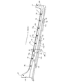
- FIG. 5 is an overall perspective view of the side sill garnish.
- the front-rear direction, the left-right direction (vehicle width direction), and the up-down direction are defined with reference to an occupant seated in the driver's seat.
- the side sill 11 arranged in the front-rear direction along the lower edge of the door opening on the side of the vehicle body of the automobile is joined to the upper and lower sides of the side sill inner 12 having a hat-like cross section that opens outward in the vehicle width direction.
- the flanges 12a and 12b and the upper and lower joint flanges 13a and 13b of the stiffener 13 having a hat-shaped cross section that opens inward in the vehicle width direction are coupled to each other, and the upper and lower joint flanges of the side sill outer 14 having a substantially L-shaped cross section.
- 14a and 14b are respectively connected to the joint flange 13a on the upper side of the stiffener 13 and the outer wall in the vehicle width direction to form a closed section.
- the side sill garnish 15 made of synthetic resin that covers the outer side and the lower side of the side sill 11 includes an upper wall 15a extending outward in the vehicle width direction, and a vehicle width direction of the upper wall 15a.
- a side wall 15b extending downward from the outer end, a lower wall 15c extending inward in the vehicle width direction from the lower end of the side wall 15b, and a thin hinge portion 15d extending in the front-rear direction to the inner end in the vehicle width direction of the lower wall 15c.
- the vehicle further includes an extension portion 15e extending inward in the vehicle width direction, and rising portions 15f and 15f rising from the front and rear end portions of the side wall 15b.
- Eight mounting holes 14d are formed in the outer wall 14c of the side sill outer 14 at predetermined intervals in the front-rear direction, and eight brackets 16 for supporting the side sill garnish 15 are formed in these mounting holes 14d. Each can be attached.
- the front and rear rising portions 15f and 15f of the side sill garnish 15 are fixed to the front pillar and the rear pillar by clips 17 and 17, respectively, and a plurality of recesses 15j formed in the extension 15e of the side sill garnish 15 include a plurality of It is fixed to the lower wall of the stiffener 13 with a clip 18.
- the bracket 16 made of synthetic resin includes a garnish support portion 19 that supports the side sill garnish 15 and a clip portion 20 that is coupled to the mounting hole 14 d of the side sill outer 14.
- the garnish support portion 19 includes a vertical wall portion 19a formed in a square plate shape, a horizontal wall portion 19b extending from the vertical wall portion 19a outward in the vehicle width direction, and three triangles connecting the vertical wall portion 19a and the horizontal wall portion 19b. .. Are formed, and inclined wall portions 19c are formed at the outer ends in the vehicle width direction of the ribs 19d.
- the inclined walls 19c are inclined with respect to the vertical direction and the horizontal direction.
- the vertical wall portion 19a, the horizontal wall portion 19b, the inclined wall portion 19c,... Are arranged in a substantially triangular shape when viewed in the front-rear direction.
- an insertion groove 19e having a V-shaped cross section that is recessed downward is formed at the inner end in the vehicle width direction of the lateral wall portion 19b of the garnish support portion 19.
- Two upper and lower guide protrusions 19f, 19f extending in the front-rear direction are formed on the inner wall surface on the outer side in the vehicle width direction of the insertion groove 19e.
- a second engaging claw 19g is formed at the upper end of the vertical wall portion 19a so as to protrude outward in the vehicle width direction toward the inside of the insertion groove 19e, and is recessed downward at the outer end in the vehicle width direction of the horizontal wall portion 19b.
- a recessed portion 19h is formed.
- a strip-shaped connecting wall 15g (see FIG. 4) that extends in the front-rear direction from the lower surface on the inner end side in the vehicle width direction of the upper wall 15a of the side sill garnish 15 hangs downward.
- first engaging claws 15h are formed at positions corresponding to the brackets 16 with the lower ends thereof being thick and projecting inward in the vehicle width direction.
- a step portion 15i is formed at the outer end in the vehicle width direction of the upper wall 15a to be fitted from above into the recess portion 19h of the lateral wall portion 19b of the garnish support portion 19 of the bracket 16.
- the clip portion 20 of the bracket 16 includes a washer 20a that protrudes annularly from the inner surface in the vehicle width direction of the vertical wall portion 19a of the garnish support portion 19, and a conical main body portion 20b that protrudes inward in the vehicle width direction from the center of the washer 20a. And a pair of claw portions 20c and 20c projecting elastically outward in the radial direction from the outer peripheral surface of the main body portion 20b.
- the main body portion 20 b of the clip portion 20 of each bracket 16 is inserted into the plurality of mounting holes 14 d provided in the side sill outer 14, and the pair of claw portions 20 c and 20 c are attached.
- the side sill outer 14 is locked to the back surface of the outer wall 14c. In this state, when the outer wall 14c of the side sill outer 14 is sandwiched between the washer 20a of the clip portion 20 and the pair of claws 20c, 20c, the brackets 16 are easily and firmly fixed to the side sill 11.
- the extension portion 15e connected to the lower wall 15c of the side sill garnish 15 via the thin hinge portion 15d is rotated upward, and along the lower surface of the side sill 11, the plurality of clips 18. Lock to the bottom.
- the extension part 15e is rotatably connected to the lower wall 15c of the side sill garnish 15 via the thin hinge part 15d, the assembly of the side sill garnish 15 to the side sill 11 is facilitated.
- the front and rear rising portions 15f and 15f of the side sill garnish 15 are engaged with the front pillar and the rear pillar of the vehicle body by clips 17 and 17, respectively. Fixed to be immovable in the direction and up and down direction.
- the vertical wall portion 19a, the horizontal wall portion 19b, the inclined wall portion 19c,... Of the garnish support portion 19 of each bracket 16 are configured in a substantially triangular shape when viewed in the front-rear direction.
- the wall portion 19a is in contact with the outer surface in the vehicle width direction of the outer wall 14c of the side sill 11
- the lateral wall portion 19b is in contact with the lower surface of the upper wall 15a of the side sill garnish 15
- the inclined wall portion 19c is formed on the upper wall 15a of the side sill garnish 15.
- the lower surface and the outer surface in the vehicle width direction of the outer wall 14c of the side sill 11 are connected.
- the rigidity of the side sill garnish 15 can be enhanced to improve the merchantability.
- the side sill garnish 15 can be positioned with respect to the bracket 16.
- the downward load applied to the side sill garnish 15 can be efficiently transmitted and supported to the inclined wall portions 19c of the bugarnish support portion 19.
- the inclined wall portions 19c are formed at the edges of the three ribs 19d that connect the vertical wall portion 19a and the horizontal wall portion 19b, the space between the three ribs 19d becomes a thinning space, The weight can be reduced as compared with the case where the garnish support portion 19 is configured to be solid.
- the side sill garnish 15 is removed with the clips 17 and 17 of the front and rear rising portions 15f and 15f of the side sill garnish 15 removed and the clips 18 of the extension 15e removed. Slide slightly in the front-rear direction with respect to the side sill 11. Then, the first engaging claws 15h of the side sill garnish 15 are separated from the second engaging claws 19g of the garnish support portion 19 in the front-rear direction, so that the side sill garnish 15 is inserted into the insertion groove 19e of the garnish support portion 19.
- the side sill garnish 15 can be separated from the brackets 16 by pulling upward along the inner wall surface on the outer side in the width direction and outward in the vehicle width direction.
- the guide protrusions 19f and 19f provided on the inner wall surface on the outer side in the vehicle width direction of the insertion grooves 19e are connected to the first engaging claws 15h of the side sill garnish 15. Since the contact is made, the frictional force is reduced and the side sill garnish 15 can be easily slid.
- the plurality of first engaging claws 15h are integrated with the band-shaped connecting wall 15g hanging from the upper wall 15a of the side sill garnish 15, the rigidity of the first engaging claws 15h can be increased.
- the side sill garnish 15 is slid in the front-rear direction with respect to the side sill 11 to disengage the first engaging claws 15h... And the second engaging claws 19g, the side sill garnish 15 is provided on the bracket 16.
- the side sill garnish 15 can be easily separated from the side sill 11 simply by pulling the upper part along the insertion groove 19e inclined outward in the vehicle width direction, so that the side sill garnish 15 interferes with the side sill 11 and is damaged or the paint is peeled off. Can be prevented.
- the side sill garnish 15 is supported on the side sill 11 using eight brackets 16..., But the number of brackets 16 is arbitrary.
Landscapes
- Engineering & Computer Science (AREA)
- Mechanical Engineering (AREA)
- Chemical & Material Sciences (AREA)
- Combustion & Propulsion (AREA)
- Transportation (AREA)
- Vehicle Interior And Exterior Ornaments, Soundproofing, And Insulation (AREA)
- Body Structure For Vehicles (AREA)
Abstract
サイドシルガーニッシュの取付構造において、サイドシル(11)の車幅方向外壁(14c)に設けたブラケット(16)にサイドシルガーニッシュ(15)が着脱自在に取り付けられる。ブラケットのガーニッシュ支持部(19)は縦壁部(19a)、横壁部(19b)および傾斜壁部(19c)を有して前後方向視で略三角形状に構成され、縦壁部がサイドシルの外壁の車幅方向外面に当接し、横壁部がサイドシルガーニッシュの上壁(15a)の下面に当接し、傾斜壁部がサイドシルガーニッシュの上壁の下面とサイドシルの外壁の車幅方向外面とを接続するので、サイドシルガーニッシュに加わる下向きの荷重をガーニッシュ支持部で支持してサイドシルの外壁に効率的に伝達することで、サイドシルガーニッシュの剛性感を簡単な構造で高めることができる。
Description
本発明は、前後方向に配置されたサイドシルの車幅方向外壁に設けたブラケットにサイドシルガーニッシュを着脱自在に取り付けるサイドシルガーニッシュの取付構造に関する。
サイドシルの外壁にブラケットを両面接着テープで接着し、サイドシルガーニッシュ(サイドアンダースポイラー)の上壁の下面に設けた取付部の挿入突起部をブラケットの挿入溝に上方から挿入して係合させることで、サイドシルの外壁にサイドシルガーニッシュを着脱自在に取り付けるものが、下記特許文献1により公知である。
ところで、上記従来のものは、サイドシルガーニッシュの上壁が車幅方向に幅狭に形成されているが、サイドシルガーニッシュの上壁が車幅方向外側に大きく張り出している場合には、乗降する乗員の足がサイドシルガーニッシュの上壁に当たって下向きの荷重が加わる可能性がある。このような場合に、下向きの荷重によりサイドシルガーニッシュが容易に変形してしまうと、剛性感が損なわれて商品性が低下する虞がある。
本発明は前述の事情に鑑みてなされたもので、サイドシルにブラケットを介して取り付けられるサイドシルガーニッシュの剛性感を簡単な構造で高めることを目的とする。
上記目的を達成するために、本発明によれば、前後方向に配置されたサイドシルの車幅方向外壁に設けたブラケットにサイドシルガーニッシュを着脱自在に取り付けるサイドシルガーニッシュの取付構造であって、前記ブラケットは前記サイドシルの前記外壁から車幅方向外側に突出するガーニッシュ支持部を備え、前記ガーニッシュ支持部は縦壁部、横壁部および傾斜壁部を有して前後方向視で略三角形状に構成され、前記縦壁部が前記サイドシルの前記外壁の車幅方向外面に当接し、前記横壁部が前記サイドシルガーニッシュの上壁の下面に当接し、前記傾斜壁部が前記サイドシルガーニッシュの前記上壁の下面と前記サイドシルの前記外壁の車幅方向外面とを接続することを第1の特徴とするサイドシルガーニッシュの取付構造が提案される。
また本発明によれば、前記第1の特徴に加えて、前記サイドシルガーニッシュは前記ブラケットに対応する位置に前記上壁から垂下する第1係合爪を備えるとともに、前記ブラケットの前記横壁部は、前記第1係合爪が上方から挿入される挿入溝と、前記挿入溝に挿入された前記第1係合爪に車幅方向内側から係合可能な第2係合爪とを備え、前記挿入溝は上部が車幅方向外側に傾斜することを第2の特徴とするサイドシルガーニッシュの取付構造が提案される。
また本発明によれば、前記第2の特徴に加えて、前記ブラケットは前記サイドシルの長手方向に沿って所定間隔で複数個設けられ、前記サイドシルガーニッシュはその長手方向に沿って前記上壁から垂下する帯状の連結壁を備え、前記第1係合爪は前記連結壁上に所定間隔で配置されることを第3の特徴とするサイドシルガーニッシュの取付構造が提案される。
また本発明によれば、前記第2または第3の特徴に加えて、前記挿入溝の車幅方向外側の内壁面に前後方向に延びるガイド突起が形成されることを第4の特徴とするサイドシルガーニッシュの取付構造が提案される。
また本発明によれば、前記第1~第4の何れか1つの特徴に加えて、前記ブラケットは前記サイドシルの前記外壁に固定されるクリップ部を備えることを第5の特徴とするサイドシルガーニッシュの取付構造が提案される。
また本発明によれば、前記第1~第5の何れか1つの特徴に加えて、前記サイドシルガーニッシュの下壁の車幅方向内端に、前記サイドシルの下面を覆う延長部が薄肉ヒンジ部を介して連結されることを第6の特徴とするサイドシルガーニッシュの取付構造が提案される。
また本発明によれば、前記第1~第6の何れか1つの特徴に加えて、前記サイドシルガーニッシュの前記上壁には段部が形成され、前記ブラケットの前記横壁部には前記段部が上方から係合する凹部が形成されることを第7の特徴とするサイドシルガーニッシュの取付構造が提案される。
また本発明によれば、前記第1~第7の何れか1つの特徴に加えて、前記ブラケットの前記ガーニッシュ支持部は前記横壁部および前記縦壁部を接続する複数の略三角形状のリブを備え、前記リブの端縁に前記傾斜壁部が形成されることを第8の特徴とするサイドシルガーニッシュの取付構造が提案される。
また本発明によれば、前記第5の特徴に加えて、前記ブラケットの前記クリップ部は、前記サイドシルの前記外壁に形成された取付孔の両側にそれぞれ係合する爪部およびワッシャを備えることを第9の特徴とするサイドシルガーニッシュの取付構造が提案される。
また本発明によれば、前記第1~第9の何れか1つの特徴に加えて、前記サイドシルガーニッシュは、車体のドア開口部の前端よりも前方位置と後端よりも後方位置とで車体に移動不能に固定されることを第10の特徴とするサイドシルガーニッシュの取付構造が提案される。
本発明の第1の特徴によれば、前後方向に配置されたサイドシルの車幅方向外壁に設けたブラケットにサイドシルガーニッシュが着脱自在に取り付けられる。ブラケットはサイドシルの外壁から車幅方向外側に突出するガーニッシュ支持部を備え、ガーニッシュ支持部は縦壁部、横壁部および傾斜壁部を有して前後方向視で略三角形状に構成され、縦壁部がサイドシルの外壁の車幅方向外面に当接し、横壁部がサイドシルガーニッシュの上壁の下面に当接し、傾斜壁部がサイドシルガーニッシュの上壁の下面とサイドシルの外壁の車幅方向外面とを接続するので、乗降する乗員の足がサイドシルガーニッシュの上壁に当たって下向きの荷重が加わったときに、その荷重をガーニッシュ支持部で支持してサイドシルの外壁に効率的に伝達することで、サイドシルガーニッシュの剛性感を高めて商品性を向上させることができる。
また本発明の第2の特徴によれば、サイドシルガーニッシュはブラケットに対応する位置に上壁から垂下する第1係合爪を備えるとともに、ブラケットの横壁部は、第1係合爪が上方から挿入される挿入溝と、挿入溝に挿入された第1係合爪に車幅方向内側から係合可能な第2係合爪とを備え、挿入溝は上部が車幅方向外側に傾斜するので、第1係合爪および第2係合爪の係合によりブラケットに対してサイドシルガーニッシュを強固に固定できるだけでなく、サイドシルガーニッシュを車幅方向外側に向かって斜め上方に引くことで挿入溝に沿ってスムーズに分離することが可能となり、サイドシルガーニッシュがサイドシルと干渉して傷付いたり塗装が剥がれたりするのを防止することができる。
また本発明の第3の特徴によれば、ブラケットはサイドシルの長手方向に沿って所定間隔で複数個設けられ、サイドシルガーニッシュはその長手方向に沿って上壁から垂下する帯状の連結壁を備え、第1係合爪は連結壁上に所定間隔で配置されるので、連結壁で複数の第1係合爪を連結して剛性を高めるとともに、サイドシルガーニッシュをブラケットに対して前後方向スライドさせることで、第1係合爪および第2係合爪の係合を簡単に外してブラケットからサイドシルガーニッシュを取り外すことができる。
また本発明の第4の特徴によれば、挿入溝の車幅方向外側の内壁面に前後方向に延びるガイド突起が形成されるので、サイドシルガーニッシュをブラケットに対して前後方向にスライドさせる際に、ブラケットとの間の摩擦力を低減してサイドシルガーニッシュを容易にスライドさせることができる。
また本発明の第5の特徴によれば、ブラケットはサイドシルの外壁に固定されるクリップ部を備えるので、ブラケットをサイドシルの外壁に容易に取り付けることができる。
また本発明の第6の特徴によれば、サイドシルガーニッシュの下壁の車幅方向内端に、サイドシルの下面を覆う延長部が薄肉ヒンジ部を介して連結されるので、サイドシルガーニッシュの延長部でサイドシルの下面を覆うことができるだけでなく、延長部を薄肉ヒンジ部で折り曲げることでサイドシルガーニッシュの取り付けを容易に行うことができる。
また本発明の第7の特徴によれば、サイドシルガーニッシュの上壁には段部が形成され、ブラケットの横壁部には段部が上方から係合する凹部が形成されるので、サイドシルガーニッシュをブラケットに対して位置決めできるだけでなく、サイドシルガーニッシュに加わる下向きの荷重をブラケットの傾斜壁部に効率的に伝達して支持することができる。
また本発明の第8の特徴によれば、ブラケットのガーニッシュ支持部は横壁部および縦壁部を接続する複数の略三角形状のリブを備え、リブの端縁に傾斜壁部が形成されるので、ガーニッシュ支持部を中実に構成する場合に比べて重量を削減することができる。
また本発明の第9の特徴によれば、ブラケットのクリップ部は、サイドシルの外壁に形成された取付孔の両側にそれぞれ係合する爪部およびワッシャを備えるので、ブラケットをサイドシルの側壁に形成された取付孔に確実に固定することができる。
また本発明の第10の特徴によれば、サイドシルガーニッシュは、車体のドア開口部の前端よりも前方位置と後端よりも後方位置とで車体に移動不能に固定されるので、サイドシルガーニッシュがブラケットに相対移動可能に支持されていても、そのサイドシルガーニッシュがブラケットに対して位置ずれするのを防止することができる。
11 サイドシル
14c 外壁
14d 取付孔
15 サイドシルガーニッシュ
15a 上壁
15c 下壁
15d 薄肉ヒンジ部
15e 延長部
15g 連結壁
15h 第1係合爪
15i 段部
16 ブラケット
19 ガーニッシュ支持部
19a 縦壁部
19b 横壁部
19c 傾斜壁部
19d リブ
19e 挿入溝
19f ガイド突起
19g 第2係合爪
19h 凹部
20 クリップ部
20a ワッシャ
20c 爪部
14c 外壁
14d 取付孔
15 サイドシルガーニッシュ
15a 上壁
15c 下壁
15d 薄肉ヒンジ部
15e 延長部
15g 連結壁
15h 第1係合爪
15i 段部
16 ブラケット
19 ガーニッシュ支持部
19a 縦壁部
19b 横壁部
19c 傾斜壁部
19d リブ
19e 挿入溝
19f ガイド突起
19g 第2係合爪
19h 凹部
20 クリップ部
20a ワッシャ
20c 爪部
以下、図1~図5に基づいて本発明の実施の形態を説明する。なお、本明細書における前後方向、左右方向(車幅方向)および上下方向は運転席に着座した乗員を基準として定義される。
図1に示すように、自動車の車体側部のドア開口の下縁に沿って前後方向に配置されるサイドシル11は、車幅方向外向きに開放するハット状断面のサイドシルインナー12の上下の接合フランジ12a,12bと、車幅方向内向きに開放するハット状断面のスチフナ13の上下の接合フランジ13a,13bとを相互に結合し、更に略L字状断面のサイドシルアウター14の上下の接合フランジ14a,14bを、スチフナ13の上側の接合フランジ13aおよび車幅方向外壁にそれぞれ結合して閉断面に構成される。
図1および図5に示すように、サイドシル11の車幅方向外側および下側を覆う合成樹脂製のサイドシルガーニッシュ15は、車幅方向外向きに延びる上壁15aと、上壁15aの車幅方向外端から下向きに延びる側壁15bと、側壁15bの下端から車幅方向内向きに延びる下壁15cと、下壁15cの車幅方向内端に前後方向に延びる薄肉ヒンジ部15dを介して連続して更に車幅方向内向きに延びる延長部15eと、側壁15bの前後方向端部から起立する立ち上げ部15f,15fとを備える。
サイドシルアウター14の外壁14cには前後方向に所定間隔で8個の取付孔14d…が形成されており、これらの取付孔14d…に、サイドシルガーニッシュ15を支持するための8個のブラケット16…がそれぞれ取り付けられる。サイドシルガーニッシュ15の前後の立ち上げ部15f,15fは、フロントピラーおよびリヤピラーにそれぞれクリップ17,17で固定されるとともに、サイドシルガーニッシュ15の延長部15eに形成された複数の凹部15j…が、複数のクリップ18…でスチフナ13の下壁に固定される。
図2~図4に示すように、合成樹脂製のブラケット16は、サイドシルガーニッシュ15を支持するガーニッシュ支持部19と、サイドシルアウター14の取付孔14dに結合されるクリップ部20とから構成される。ガーニッシュ支持部19は、四角板状に形成された縦壁部19aと、縦壁部19aから車幅方向外側に延びる横壁部19bと、縦壁部19aおよび横壁部19bを接続する3枚の三角形状のリブ19d…とを備え、リブ19d…の車幅方向外端には鉛直方向および水平方向に対して傾斜する傾斜壁部19c…が形成される。前後方向視で、縦壁部19a、横壁部19bおよび傾斜壁部19c…は略三角形状に配置される。
更に、ガーニッシュ支持部19の横壁部19bの車幅方向内端には下向きに窪むV字状断面の挿入溝19eが形成される。挿入溝19eの車幅方向外側の内壁面には前後方向に延びる上下2本のガイド突起19f,19fが形成される。また縦壁部19aの上端には挿入溝19eの内部に向かって車幅方向外側に突出する第2係合爪19gが形成されるとともに、横壁部19bの車幅方向外端には下向きに窪む凹部19hが形成される。
一方、サイドシルガーニッシュ15の上壁15aの車幅方向内端側の下面から前後方向に延びる帯状の連結壁15g(図4参照)が下向きに垂下する。帯状の連結壁15gのうち、ブラケット16…に対応する位置には、その下端を肉厚にして車幅方向内向きに突出させた第1係合爪15h…が形成される。また上壁15aの車幅方向外端には、ブラケット16のガーニッシュ支持部19の横壁部19bの凹部19hに上方から嵌合する段部15iが形成される。
ブラケット16のクリップ部20は、ガーニッシュ支持部19の縦壁部19aの車幅方向内面から環状に突出するワッシャ20aと、ワッシャ20aの中央から車幅方向内向きに突出する円錐状の本体部20bと、本体部20bの外周面から径方向外向きに弾発的に突出する一対の爪部20c,20cとを備える。
次に、上記構成を備えた本発明の実施の形態の作用を説明する。
サイドシル11にサイドシルガーニッシュ15を組み付けるには、まずサイドシルアウター14に設けた複数の取付孔14d…に、各々のブラケット16のクリップ部20の本体部20bを挿入し、一対の爪部20c,20cをサイドシルアウター14の外壁14cの裏面に係止する。この状態で、クリップ部20のワッシャ20aと一対の爪部20c,20cとの間にサイドシルアウター14の外壁14cが挟まれることで、ブラケット16…がサイドシル11に容易かつ強固に固定される。
続いて、サイドシルガーニッシュ15の上壁15aから垂下する連結壁15gを、ブラケット16のガーニッシュ支持部19の挿入溝19eの傾斜した内壁面に沿って下向きかつ車幅方向内向きに挿入すると、サイドシルガーニッシュ15の第1係合爪15h…がガーニッシュ支持部19の第2係合爪19gに係合し、サイドシルガーニッシュ15は上方に抜けないようにブラケット16…に係止される。
続いて、サイドシルガーニッシュ15の下壁15cに薄肉ヒンジ部15dを介して連結された延長部15eを上向きに回転させ、サイドシル11の下面に沿わせた状態で、複数のクリップ18…でサイドシル11の下面に係止する。このように、サイドシルガーニッシュ15の下壁15cに薄肉ヒンジ部15dを介して延長部15eを回動可能に連結したので、サイドシル11に対するサイドシルガーニッシュ15の組み付けが容易になる。そして、サイドシルガーニッシュ15の前後の立ち上げ部15f,15fを、それぞれ車体のフロントピラーおよびリヤピラーにクリップ17,17で係止することで、サイドシルガーニッシュ15がサイドシル11に対して、前後方向、車幅方向および上下方向に移動不能に固定される。
このようにしてサイドシルガーニッシュ15が取り付けられた状態で、各ブラケット16のガーニッシュ支持部19の縦壁部19a、横壁部19bおよび傾斜壁部19c…が前後方向視で略三角形状に構成され、縦壁部19aがサイドシル11の外壁14cの車幅方向外面に当接し、横壁部19bがサイドシルガーニッシュ15の上壁15aの下面に当接し、かつ傾斜壁部19c…がサイドシルガーニッシュ15の上壁15aの下面とサイドシル11の外壁14cの車幅方向外面とを接続する。その結果、乗降する乗員の足がサイドシルガーニッシュ15の上壁15aに当たって下向きの荷重が加わったときに、その荷重をガーニッシュ支持部19…で支持してサイドシル11の外壁14cに効率的に伝達することで、サイドシルガーニッシュ15の剛性感を高めて商品性を向上させることができる。
特に、サイドシルガーニッシュ15の上壁15aに形成した段部15iが、ガーニッシュ支持部19の横壁部19bに形成した凹部19hに上方から係合するので、サイドシルガーニッシュ15をブラケット16…に対して位置決めできるだけでなく、サイドシルガーニッシュ15に加わる下向きの荷重をブガーニッシュ支持部19の傾斜壁部19c…に効率的に伝達して支持することができる。
しかも傾斜壁部19c…は縦壁部19aおよび横壁部19bを連結する3枚のリブ19d…の縁部に形成されるので、3枚のリブ19d…の間が肉抜き空間となることで、ガーニッシュ支持部19を中実に構成する場合に比べて重量を削減することができる。
サイドシルガーニッシュ15をサイドシル11から取り外すには、先ずサイドシルガーニッシュ15の前後の立ち上げ部15f,15fのクリップ17,17を外すとともに、延長部15eのクリップ18…を外した状態で、サイドシルガーニッシュ15をサイドシル11に対して前後方向に僅かにスライドさせる。するとサイドシルガーニッシュ15の第1係合爪15h…がガーニッシュ支持部19…の第2係合爪19g…から前後方向に分離するため、サイドシルガーニッシュ15をガーニッシュ支持部19…の挿入溝19e…の車幅方向外側の内壁面に沿って上方かつ車幅方向外側に引くことで、サイドシルガーニッシュ15をブラケット16…から分離することができる。
サイドシルガーニッシュ15をサイドシル11に対して前後方向にスライドさせるとき、挿入溝19e…の車幅方向外側の内壁面に設けたガイド突起19f,19fがサイドシルガーニッシュ15の第1係合爪15h…に線接触するので、摩擦力が低減してサイドシルガーニッシュ15のスライドが容易になる。しかもサイドシルガーニッシュ15の上壁15aから垂下する帯状の連結壁15gに複数の第1係合爪15h…が一体化されるので、第1係合爪15h…の剛性を高めることができる。
以上のように、サイドシルガーニッシュ15をサイドシル11に対して前後方向にスライドさせて第1係合爪15h…および第2係合爪19gの係合を解除した後、サイドシルガーニッシュ15をブラケット16に設けられた上部が車幅方向外側に傾斜する挿入溝19eに沿って引くだけで、サイドシルガーニッシュ15をサイドシル11から簡単に分離できるので、サイドシルガーニッシュ15がサイドシル11と干渉して傷付いたり塗装が剥がれたりするのを防止することができる。
以上、本発明の実施の形態を説明したが、本発明はその要旨を逸脱しない範囲で種々の設計変更を行うことが可能である。
例えば、実施の形態では8個のブラケット16…を用いてサイドシル11にサイドシルガーニッシュ15を支持しているが、ブラケット16…の数は任意である。
Claims (10)
- 前後方向に配置されたサイドシル(11)の車幅方向外壁(14c)に設けたブラケット(16)にサイドシルガーニッシュ(15)を着脱自在に取り付けるサイドシルガーニッシュの取付構造であって、
前記ブラケット(16)は前記サイドシル(11)の前記外壁(14c)から車幅方向外側に突出するガーニッシュ支持部(19)を備え、前記ガーニッシュ支持部(19)は縦壁部(19a)、横壁部(19b)および傾斜壁部(19c)を有して前後方向視で略三角形状に構成され、前記縦壁部(19a)が前記サイドシル(11)の前記外壁(14c)の車幅方向外面に当接し、前記横壁部(19b)が前記サイドシルガーニッシュ(15)の上壁(15a)の下面に当接し、前記傾斜壁部(19c)が前記サイドシルガーニッシュ(15)の前記上壁(15a)の下面と前記サイドシル(11)の前記外壁(14c)の車幅方向外面とを接続することを特徴とするサイドシルガーニッシュの取付構造。 - 前記サイドシルガーニッシュ(15)は前記ブラケット(16)に対応する位置に前記上壁(15a)から垂下する第1係合爪(15h)を備えるとともに、前記ブラケット(16)の前記横壁部(19b)は、前記第1係合爪(15h)が上方から挿入される挿入溝(19e)と、前記挿入溝(19e)に挿入された前記第1係合爪(15h)に車幅方向内側から係合可能な第2係合爪(19g)とを備え、前記挿入溝(19e)は上部が車幅方向外側に傾斜することを特徴とする、請求項1に記載のサイドシルガーニッシュの取付構造。
- 前記ブラケット(16)は前記サイドシル(11)の長手方向に沿って所定間隔で複数個設けられ、前記サイドシルガーニッシュ(15)はその長手方向に沿って前記上壁(15a)から垂下する帯状の連結壁(15g)を備え、前記第1係合爪(15h)は前記連結壁(15g)上に所定間隔で配置されることを特徴とする、請求項2に記載のサイドシルガーニッシュの取付構造。
- 前記挿入溝(19e)の車幅方向外側の内壁面に前後方向に延びるガイド突起(19f)が形成されることを特徴とする、請求項2または請求項3に記載のサイドシルガーニッシュの取付構造。
- 前記ブラケット(16)は前記サイドシル(11)の前記外壁(14c)に固定されるクリップ部(20)を備えることを特徴とする、請求項1~請求項4の何れか1項に記載のサイドシルガーニッシュの取付構造。
- 前記サイドシルガーニッシュ(15)の下壁(15c)の車幅方向内端に、前記サイドシル(11)の下面を覆う延長部(15e)が薄肉ヒンジ部(15d)を介して連結されることを特徴とする、請求項1~請求項5の何れか1項に記載のサイドシルガーニッシュの取付構造。
- 前記サイドシルガーニッシュ(15)の前記上壁(15a)には段部(15i)が形成され、前記ブラケット(16)の前記横壁部(19b)には前記段部(15i)が上方から係合する凹部(19h)が形成されることを特徴とする、請求項1~請求項6の何れか1項に記載のサイドシルガーニッシュの取付構造。
- 前記ブラケット(16)の前記ガーニッシュ支持部(19)は前記横壁部(19b)および前記縦壁部(19a)を接続する複数の略三角形状のリブ(19d)を備え、前記リブ(19d)の端縁に前記傾斜壁部(19c)が形成されることを特徴とする、請求項1~請求項7の何れか1項に記載のサイドシルガーニッシュの取付構造。
- 前記ブラケット(16)の前記クリップ部(20)は、前記サイドシル(11)の前記外壁(14c)に形成された取付孔(14d)の両側にそれぞれ係合する爪部(20c)およびワッシャ(20a)を備えることを特徴とする、請求項5に記載のサイドシルガーニッシュの取付構造。
- 前記サイドシルガーニッシュ(15)は、車体のドア開口部の前端よりも前方位置と後端よりも後方位置とで、車体に移動不能に固定されることを特徴とする、請求項1~請求項9の何れか1項に記載のサイドシルガーニッシュの取付構造。
Priority Applications (1)
| Application Number | Priority Date | Filing Date | Title |
|---|---|---|---|
| JP2020508194A JP6953618B2 (ja) | 2018-03-22 | 2019-03-08 | サイドシルガーニッシュの取付構造 |
Applications Claiming Priority (2)
| Application Number | Priority Date | Filing Date | Title |
|---|---|---|---|
| JP2018-054804 | 2018-03-22 | ||
| JP2018054804 | 2018-03-22 |
Publications (1)
| Publication Number | Publication Date |
|---|---|
| WO2019181567A1 true WO2019181567A1 (ja) | 2019-09-26 |
Family
ID=67986191
Family Applications (1)
| Application Number | Title | Priority Date | Filing Date |
|---|---|---|---|
| PCT/JP2019/009371 Ceased WO2019181567A1 (ja) | 2018-03-22 | 2019-03-08 | サイドシルガーニッシュの取付構造 |
Country Status (2)
| Country | Link |
|---|---|
| JP (1) | JP6953618B2 (ja) |
| WO (1) | WO2019181567A1 (ja) |
Cited By (1)
| Publication number | Priority date | Publication date | Assignee | Title |
|---|---|---|---|---|
| KR20210077254A (ko) * | 2019-12-17 | 2021-06-25 | (주)엘지하우시스 | 차량용 가니쉬 결합구조체 |
Citations (5)
| Publication number | Priority date | Publication date | Assignee | Title |
|---|---|---|---|---|
| JPH08132980A (ja) * | 1994-11-07 | 1996-05-28 | Ikeda Bussan Co Ltd | 自動車用ルーフライニング |
| JP2004168215A (ja) * | 2002-11-21 | 2004-06-17 | Honda Motor Co Ltd | サイドシルガーニッシュの取付構造 |
| JP2009002411A (ja) * | 2007-06-20 | 2009-01-08 | Toyota Auto Body Co Ltd | 樹脂成形品組付用のクリップ及びこれを用いた樹脂成形品の組付構造 |
| WO2014068653A1 (ja) * | 2012-10-30 | 2014-05-08 | 本田技研工業株式会社 | 車両用外装部品の取付構造 |
| JP2015101231A (ja) * | 2013-11-26 | 2015-06-04 | スズキ株式会社 | 車体側部構造 |
-
2019
- 2019-03-08 WO PCT/JP2019/009371 patent/WO2019181567A1/ja not_active Ceased
- 2019-03-08 JP JP2020508194A patent/JP6953618B2/ja not_active Expired - Fee Related
Patent Citations (5)
| Publication number | Priority date | Publication date | Assignee | Title |
|---|---|---|---|---|
| JPH08132980A (ja) * | 1994-11-07 | 1996-05-28 | Ikeda Bussan Co Ltd | 自動車用ルーフライニング |
| JP2004168215A (ja) * | 2002-11-21 | 2004-06-17 | Honda Motor Co Ltd | サイドシルガーニッシュの取付構造 |
| JP2009002411A (ja) * | 2007-06-20 | 2009-01-08 | Toyota Auto Body Co Ltd | 樹脂成形品組付用のクリップ及びこれを用いた樹脂成形品の組付構造 |
| WO2014068653A1 (ja) * | 2012-10-30 | 2014-05-08 | 本田技研工業株式会社 | 車両用外装部品の取付構造 |
| JP2015101231A (ja) * | 2013-11-26 | 2015-06-04 | スズキ株式会社 | 車体側部構造 |
Cited By (2)
| Publication number | Priority date | Publication date | Assignee | Title |
|---|---|---|---|---|
| KR20210077254A (ko) * | 2019-12-17 | 2021-06-25 | (주)엘지하우시스 | 차량용 가니쉬 결합구조체 |
| KR102608786B1 (ko) * | 2019-12-17 | 2023-11-30 | (주)엘엑스하우시스 | 차량용 가니쉬 결합구조체 |
Also Published As
| Publication number | Publication date |
|---|---|
| JPWO2019181567A1 (ja) | 2021-01-14 |
| JP6953618B2 (ja) | 2021-10-27 |
Similar Documents
| Publication | Publication Date | Title |
|---|---|---|
| JP5373009B2 (ja) | 自動車の車体構造 | |
| JP6348930B2 (ja) | 車体構造 | |
| JP5032876B2 (ja) | 自動車用ウェザーストリップの取付構造 | |
| JP2018012383A (ja) | 車両用補機のカバー構造 | |
| WO2019181567A1 (ja) | サイドシルガーニッシュの取付構造 | |
| JP5914039B2 (ja) | 車両のスカッフプレート組付け構造 | |
| JP5660828B2 (ja) | ウェザーストリップの取付構造 | |
| JPH11170925A (ja) | 自動車のテールエンドメンバートリム構造 | |
| JP2010280246A (ja) | 車両用ホイールアーチガーニッシュの取付構造 | |
| JP2019177755A (ja) | サイドバイザー及びサイドバイザーの取付構造 | |
| JP2011098581A (ja) | ピラートリムの取り付け構造 | |
| JP6520001B2 (ja) | 内装部材の構造 | |
| JP5315541B2 (ja) | 車両用インストルメントパネルの取付構造 | |
| JP4747797B2 (ja) | 自動車のバンパ取付構造 | |
| JP5513770B2 (ja) | ウェザーストリップの取付構造 | |
| JP4837542B2 (ja) | コンソール取付構造 | |
| JP4624177B2 (ja) | ルーフモールディングとウインドウモールディングとの連結構造 | |
| JP2024093963A (ja) | サイドバイザー及びサイドバイザーの取付構造 | |
| JP6472736B2 (ja) | ウインドデフレクタの取付構造 | |
| JP5118529B2 (ja) | トリムの接合部構造 | |
| JPH06156157A (ja) | ピラーガーニッシュの取付構造 | |
| JP6457336B2 (ja) | ウインドデフレクタの固定構造 | |
| JP2015047918A (ja) | 車両用ウェザーストリップ取付構造 | |
| JP4954787B2 (ja) | フロアカーペットの固定構造 | |
| JP2008208922A (ja) | クリップ取付け座 |
Legal Events
| Date | Code | Title | Description |
|---|---|---|---|
| 121 | Ep: the epo has been informed by wipo that ep was designated in this application |
Ref document number: 19771361 Country of ref document: EP Kind code of ref document: A1 |
|
| ENP | Entry into the national phase |
Ref document number: 2020508194 Country of ref document: JP Kind code of ref document: A |
|
| NENP | Non-entry into the national phase |
Ref country code: DE |
|
| 122 | Ep: pct application non-entry in european phase |
Ref document number: 19771361 Country of ref document: EP Kind code of ref document: A1 |