WO2019172148A1 - 車両用灯具および車両用灯具システム - Google Patents
車両用灯具および車両用灯具システム Download PDFInfo
- Publication number
- WO2019172148A1 WO2019172148A1 PCT/JP2019/008230 JP2019008230W WO2019172148A1 WO 2019172148 A1 WO2019172148 A1 WO 2019172148A1 JP 2019008230 W JP2019008230 W JP 2019008230W WO 2019172148 A1 WO2019172148 A1 WO 2019172148A1
- Authority
- WO
- WIPO (PCT)
- Prior art keywords
- light source
- light
- lamp
- vehicular lamp
- vehicle
- Prior art date
- Legal status (The legal status is an assumption and is not a legal conclusion. Google has not performed a legal analysis and makes no representation as to the accuracy of the status listed.)
- Ceased
Links
Images

Classifications
-
- F—MECHANICAL ENGINEERING; LIGHTING; HEATING; WEAPONS; BLASTING
- F21—LIGHTING
- F21S—NON-PORTABLE LIGHTING DEVICES; SYSTEMS THEREOF; VEHICLE LIGHTING DEVICES SPECIALLY ADAPTED FOR VEHICLE EXTERIORS
- F21S41/00—Illuminating devices specially adapted for vehicle exteriors, e.g. headlamps
- F21S41/10—Illuminating devices specially adapted for vehicle exteriors, e.g. headlamps characterised by the light source
- F21S41/14—Illuminating devices specially adapted for vehicle exteriors, e.g. headlamps characterised by the light source characterised by the type of light source
- F21S41/16—Laser light sources
-
- B—PERFORMING OPERATIONS; TRANSPORTING
- B60—VEHICLES IN GENERAL
- B60Q—ARRANGEMENT OF SIGNALLING OR LIGHTING DEVICES, THE MOUNTING OR SUPPORTING THEREOF OR CIRCUITS THEREFOR, FOR VEHICLES IN GENERAL
- B60Q1/00—Arrangement of optical signalling or lighting devices, the mounting or supporting thereof or circuits therefor
-
- B—PERFORMING OPERATIONS; TRANSPORTING
- B60—VEHICLES IN GENERAL
- B60Q—ARRANGEMENT OF SIGNALLING OR LIGHTING DEVICES, THE MOUNTING OR SUPPORTING THEREOF OR CIRCUITS THEREFOR, FOR VEHICLES IN GENERAL
- B60Q1/00—Arrangement of optical signalling or lighting devices, the mounting or supporting thereof or circuits therefor
- B60Q1/26—Arrangement of optical signalling or lighting devices, the mounting or supporting thereof or circuits therefor the devices being primarily intended to indicate the vehicle, or parts thereof, or to give signals, to other traffic
-
- F—MECHANICAL ENGINEERING; LIGHTING; HEATING; WEAPONS; BLASTING
- F21—LIGHTING
- F21S—NON-PORTABLE LIGHTING DEVICES; SYSTEMS THEREOF; VEHICLE LIGHTING DEVICES SPECIALLY ADAPTED FOR VEHICLE EXTERIORS
- F21S41/00—Illuminating devices specially adapted for vehicle exteriors, e.g. headlamps
- F21S41/10—Illuminating devices specially adapted for vehicle exteriors, e.g. headlamps characterised by the light source
- F21S41/12—Illuminating devices specially adapted for vehicle exteriors, e.g. headlamps characterised by the light source characterised by the type of emitted light
- F21S41/13—Ultraviolet light; Infrared light
-
- F—MECHANICAL ENGINEERING; LIGHTING; HEATING; WEAPONS; BLASTING
- F21—LIGHTING
- F21S—NON-PORTABLE LIGHTING DEVICES; SYSTEMS THEREOF; VEHICLE LIGHTING DEVICES SPECIALLY ADAPTED FOR VEHICLE EXTERIORS
- F21S41/00—Illuminating devices specially adapted for vehicle exteriors, e.g. headlamps
- F21S41/10—Illuminating devices specially adapted for vehicle exteriors, e.g. headlamps characterised by the light source
- F21S41/14—Illuminating devices specially adapted for vehicle exteriors, e.g. headlamps characterised by the light source characterised by the type of light source
- F21S41/141—Light emitting diodes [LED]
- F21S41/147—Light emitting diodes [LED] the main emission direction of the LED being angled to the optical axis of the illuminating device
-
- F—MECHANICAL ENGINEERING; LIGHTING; HEATING; WEAPONS; BLASTING
- F21—LIGHTING
- F21S—NON-PORTABLE LIGHTING DEVICES; SYSTEMS THEREOF; VEHICLE LIGHTING DEVICES SPECIALLY ADAPTED FOR VEHICLE EXTERIORS
- F21S41/00—Illuminating devices specially adapted for vehicle exteriors, e.g. headlamps
- F21S41/10—Illuminating devices specially adapted for vehicle exteriors, e.g. headlamps characterised by the light source
- F21S41/14—Illuminating devices specially adapted for vehicle exteriors, e.g. headlamps characterised by the light source characterised by the type of light source
- F21S41/141—Light emitting diodes [LED]
- F21S41/147—Light emitting diodes [LED] the main emission direction of the LED being angled to the optical axis of the illuminating device
- F21S41/148—Light emitting diodes [LED] the main emission direction of the LED being angled to the optical axis of the illuminating device the main emission direction of the LED being perpendicular to the optical axis
-
- F—MECHANICAL ENGINEERING; LIGHTING; HEATING; WEAPONS; BLASTING
- F21—LIGHTING
- F21S—NON-PORTABLE LIGHTING DEVICES; SYSTEMS THEREOF; VEHICLE LIGHTING DEVICES SPECIALLY ADAPTED FOR VEHICLE EXTERIORS
- F21S41/00—Illuminating devices specially adapted for vehicle exteriors, e.g. headlamps
- F21S41/10—Illuminating devices specially adapted for vehicle exteriors, e.g. headlamps characterised by the light source
- F21S41/14—Illuminating devices specially adapted for vehicle exteriors, e.g. headlamps characterised by the light source characterised by the type of light source
- F21S41/162—Incandescent light sources, e.g. filament or halogen lamps
-
- F—MECHANICAL ENGINEERING; LIGHTING; HEATING; WEAPONS; BLASTING
- F21—LIGHTING
- F21S—NON-PORTABLE LIGHTING DEVICES; SYSTEMS THEREOF; VEHICLE LIGHTING DEVICES SPECIALLY ADAPTED FOR VEHICLE EXTERIORS
- F21S41/00—Illuminating devices specially adapted for vehicle exteriors, e.g. headlamps
- F21S41/10—Illuminating devices specially adapted for vehicle exteriors, e.g. headlamps characterised by the light source
- F21S41/14—Illuminating devices specially adapted for vehicle exteriors, e.g. headlamps characterised by the light source characterised by the type of light source
- F21S41/17—Discharge light sources
-
- F—MECHANICAL ENGINEERING; LIGHTING; HEATING; WEAPONS; BLASTING
- F21—LIGHTING
- F21S—NON-PORTABLE LIGHTING DEVICES; SYSTEMS THEREOF; VEHICLE LIGHTING DEVICES SPECIALLY ADAPTED FOR VEHICLE EXTERIORS
- F21S41/00—Illuminating devices specially adapted for vehicle exteriors, e.g. headlamps
- F21S41/10—Illuminating devices specially adapted for vehicle exteriors, e.g. headlamps characterised by the light source
- F21S41/14—Illuminating devices specially adapted for vehicle exteriors, e.g. headlamps characterised by the light source characterised by the type of light source
- F21S41/176—Light sources where the light is generated by photoluminescent material spaced from a primary light generating element
-
- F—MECHANICAL ENGINEERING; LIGHTING; HEATING; WEAPONS; BLASTING
- F21—LIGHTING
- F21S—NON-PORTABLE LIGHTING DEVICES; SYSTEMS THEREOF; VEHICLE LIGHTING DEVICES SPECIALLY ADAPTED FOR VEHICLE EXTERIORS
- F21S41/00—Illuminating devices specially adapted for vehicle exteriors, e.g. headlamps
- F21S41/20—Illuminating devices specially adapted for vehicle exteriors, e.g. headlamps characterised by refractors, transparent cover plates, light guides or filters
- F21S41/25—Projection lenses
- F21S41/255—Lenses with a front view of circular or truncated circular outline
-
- F—MECHANICAL ENGINEERING; LIGHTING; HEATING; WEAPONS; BLASTING
- F21—LIGHTING
- F21S—NON-PORTABLE LIGHTING DEVICES; SYSTEMS THEREOF; VEHICLE LIGHTING DEVICES SPECIALLY ADAPTED FOR VEHICLE EXTERIORS
- F21S41/00—Illuminating devices specially adapted for vehicle exteriors, e.g. headlamps
- F21S41/20—Illuminating devices specially adapted for vehicle exteriors, e.g. headlamps characterised by refractors, transparent cover plates, light guides or filters
- F21S41/25—Projection lenses
- F21S41/275—Lens surfaces, e.g. coatings or surface structures
-
- F—MECHANICAL ENGINEERING; LIGHTING; HEATING; WEAPONS; BLASTING
- F21—LIGHTING
- F21S—NON-PORTABLE LIGHTING DEVICES; SYSTEMS THEREOF; VEHICLE LIGHTING DEVICES SPECIALLY ADAPTED FOR VEHICLE EXTERIORS
- F21S45/00—Arrangements within vehicle lighting devices specially adapted for vehicle exteriors, for purposes other than emission or distribution of light
- F21S45/40—Cooling of lighting devices
- F21S45/42—Forced cooling
- F21S45/43—Forced cooling using gas
-
- F—MECHANICAL ENGINEERING; LIGHTING; HEATING; WEAPONS; BLASTING
- F21—LIGHTING
- F21S—NON-PORTABLE LIGHTING DEVICES; SYSTEMS THEREOF; VEHICLE LIGHTING DEVICES SPECIALLY ADAPTED FOR VEHICLE EXTERIORS
- F21S45/00—Arrangements within vehicle lighting devices specially adapted for vehicle exteriors, for purposes other than emission or distribution of light
- F21S45/40—Cooling of lighting devices
- F21S45/47—Passive cooling, e.g. using fins, thermal conductive elements or openings
-
- F—MECHANICAL ENGINEERING; LIGHTING; HEATING; WEAPONS; BLASTING
- F21—LIGHTING
- F21V—FUNCTIONAL FEATURES OR DETAILS OF LIGHTING DEVICES OR SYSTEMS THEREOF; STRUCTURAL COMBINATIONS OF LIGHTING DEVICES WITH OTHER ARTICLES, NOT OTHERWISE PROVIDED FOR
- F21V29/00—Protecting lighting devices from thermal damage; Cooling or heating arrangements specially adapted for lighting devices or systems
- F21V29/50—Cooling arrangements
- F21V29/502—Cooling arrangements characterised by the adaptation for cooling of specific components
- F21V29/503—Cooling arrangements characterised by the adaptation for cooling of specific components of light sources
-
- F—MECHANICAL ENGINEERING; LIGHTING; HEATING; WEAPONS; BLASTING
- F21—LIGHTING
- F21V—FUNCTIONAL FEATURES OR DETAILS OF LIGHTING DEVICES OR SYSTEMS THEREOF; STRUCTURAL COMBINATIONS OF LIGHTING DEVICES WITH OTHER ARTICLES, NOT OTHERWISE PROVIDED FOR
- F21V29/00—Protecting lighting devices from thermal damage; Cooling or heating arrangements specially adapted for lighting devices or systems
- F21V29/50—Cooling arrangements
- F21V29/70—Cooling arrangements characterised by passive heat-dissipating elements, e.g. heat-sinks
- F21V29/74—Cooling arrangements characterised by passive heat-dissipating elements, e.g. heat-sinks with fins or blades
- F21V29/76—Cooling arrangements characterised by passive heat-dissipating elements, e.g. heat-sinks with fins or blades with essentially identical parallel planar fins or blades, e.g. with comb-like cross-section
Definitions
- the present invention relates to a vehicular lamp and a vehicular lamp system, and more particularly to a vehicular lamp used in a vehicle such as an automobile and a vehicular lamp system using the vehicular lamp.
- a vehicular lamp disclosed in Patent Document 1 is a lamp for forming a road surface drawing lamp unit and a light distribution pattern for visually recognizing the front of a driver in a lamp chamber formed by a lamp body and a front cover. The unit was housed.
- the present invention has been made in view of such circumstances, and an object of the present invention is to provide a technique for simplifying the structure of a vehicular lamp that can form a road surface drawing pattern and a forward viewing light distribution pattern.
- an aspect of the present invention is a vehicle lamp.
- the vehicle lamp includes a first light source for forming a road surface drawing pattern, an optical element that forms a road surface drawing pattern by controlling a traveling direction of light of the first light source, and a light distribution for visually confirming a driver's front.
- the vehicle lamp includes a first light source for forming a road surface drawing pattern, an optical element that forms a road surface drawing pattern by controlling a traveling direction of light of the first light source, and a light distribution for visually confirming a driver's front.
- a second light source for forming the pattern, and a first heat sink supporting the first light source and the second light source are provided. Also according to this aspect, the structure of the vehicular lamp can be simplified.
- the apparatus further includes a second heat sink connected to the first light source, the first heat sink includes a plurality of first fins, the second heat sink includes a plurality of second fins, The second fins may be arranged in parallel.
- the first heat sink has a base portion having a first surface on which the second light source is mounted, and a second surface that faces away from the first surface and is connected to the plurality of first fins.
- the first light source may be arranged between the plurality of first fins such that the light emission direction faces the second surface side.
- the optical element may be provided in the projection lens.
- the second light source may include a plurality of light sources, and each light source may be assigned to each of a plurality of individual regions arranged in front of the host vehicle and irradiate light to the corresponding individual region.
- the second light source further includes a low beam light source for forming a low beam light distribution pattern having a predetermined cutoff line, and the plurality of light sources are arranged in the vehicle width direction above the cutoff line. Each of the plurality of individual regions may be irradiated with light.
- Still another aspect of the present invention is a vehicle lamp system.
- the vehicle lamp system includes an imaging device that images the front of the vehicle, the vehicle lamp according to any one of the above aspects, and a control device that adjusts the optical axis of the vehicle lamp.
- the control device adjusts the optical axis based on the position of the road surface drawing pattern included in the image data acquired from the imaging device.
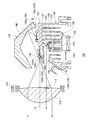
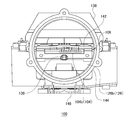
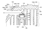
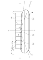
- FIG. 1 It is a figure which shows schematic structure of the vehicle lamp system which concerns on embodiment. It is a vertical sectional view of the lamp unit with which the vehicular lamp according to the embodiment is provided. It is a front view of a lamp unit. It is an expanded sectional view of the field containing the 1st light source. It is a figure which shows typically the light distribution pattern formed with the vehicle lamp which concerns on embodiment.
- FIG. 1 is a diagram showing a schematic configuration of a vehicular lamp system according to an embodiment.
- some of the components of the vehicular lamp system 1 are depicted as functional blocks. These functional blocks are realized by elements and circuits such as a CPU and a memory of a computer as a hardware configuration, and are realized by a computer program or the like as a software configuration. Those skilled in the art will understand that these functional blocks can be realized in various forms by a combination of hardware and software.
- the vehicular lamp system 1 is applied to a vehicular headlamp apparatus having a pair of headlamp units arranged on the left and right sides in front of the vehicle. Since the pair of headlamp units have a substantially symmetrical structure and have substantially the same configuration, FIG. 1 shows the structure of one headlamp unit as the vehicle lamp 2.
- the vehicular lamp system 1 includes a vehicular lamp 2, an imaging device 10, and a control device 12 as main components.
- the vehicular lamp 2 includes a lamp body 4 having an opening on the front side of the vehicle, and a translucent cover 6 attached so as to cover the opening of the lamp body 4.
- the vehicular lamp 2 includes an actuator 14 and a lamp unit 100 in a lamp chamber 8 formed by the lamp body 4 and the translucent cover 6.
- the imaging device 10 and the control device 12 are also accommodated in the lamp chamber 8.
- the imaging device 10 is a device that images the front of the vehicle.
- the imaging device 10 is configured by, for example, a conventionally known camera.
- the image data acquired by the imaging device 10 is sent to the control device 12.
- the control device 12 adjusts the optical axis of the vehicular lamp 2. Specifically, the control device 12 adjusts the optical axis O of the lamp unit 100 based on the position of the road surface drawing pattern included in the image data acquired from the imaging device 10. The road surface drawing pattern will be described in detail later. Moreover, the control apparatus 12 of this Embodiment determines the light distribution pattern which the vehicle lamp 2 forms. Note that the optical axis adjustment of the vehicular lamp 2 and the determination of the light distribution pattern may be executed by separate control devices.
- the control device 12 includes an image analysis unit 16, an optical axis displacement amount determination unit 18, an actuator control unit 20, a light distribution pattern determination unit 22, and a light source control unit 24.
- the image analysis unit 16 detects a road surface drawing pattern formed by the lamp unit 100 from the image data acquired from the imaging device 10.
- the image analysis unit 16 transmits the position information of the road surface drawing pattern to the optical axis displacement amount determination unit 18.
- the image analysis unit 16 detects a vehicle existing ahead of the host vehicle from the image data acquired from the imaging device 10.
- the image analysis unit 16 can detect the forward vehicle using a conventionally known method including algorithm recognition and deep learning.
- the image analysis unit 16 holds a feature point indicating the vehicle ahead in advance.
- the image analysis part 16 recognizes the position of a front vehicle, when the said feature point exists in image data.
- the “feature point” is, for example, a light spot of a predetermined luminous intensity or higher that appears in an estimated presence area of a headlamp of an oncoming vehicle or a tail lamp of a preceding vehicle.
- the position information of the preceding vehicle is transmitted to the light distribution pattern determination unit 22.
- the optical axis displacement amount determination unit 18 detects the amount of deviation between the predetermined initial position and the actual position with respect to the optical axis of the lamp unit 100 using the position information of the road surface drawing pattern acquired from the image analysis unit 16. Then, the amount of displacement of the lamp unit necessary for making the actual optical axis position coincide with the initial optical axis position is determined from the detected deviation amount.
- the optical axis displacement amount determining unit 18 holds ideal pattern position information in advance.
- the ideal pattern position is a position taken by the road surface drawing pattern in the image data when the lamp unit 100 takes the initial optical axis position.
- the optical axis displacement amount determination unit 18 detects the shift amount between the pattern position in the acquired image data, that is, the actual pattern position and the ideal pattern position. Then, a deviation amount between the actual optical axis position and the initial optical axis position is detected from the deviation amount of the pattern position.
- the optical axis displacement amount determination unit 18 transmits information on the amount of deviation of the optical axis position to the actuator control unit 20.
- the actuator control unit 20 determines the drive amount of the actuator 14 based on the optical axis position deviation amount acquired from the optical axis displacement amount determination unit 18. For example, the actuator control unit 20 holds in advance a conversion table in which the optical axis position deviation amount and the drive amount of the actuator 14 are associated with each other, and determines the drive amount of the actuator 14 using the conversion table. Then, the actuator control unit 20 transmits a drive signal to the actuator 14 based on the determined drive amount.
- the light distribution pattern determination unit 22 determines the light distribution pattern formed by the lamp unit 100 based on the position information of the preceding vehicle acquired from the image analysis unit 16.
- the light distribution pattern determined by the light distribution pattern determination unit 22 includes a light shielding unit or a light reduction unit that overlaps with the position where the vehicle ahead is present.
- the light distribution pattern determination unit 22 transmits a signal indicating the determined light distribution pattern to the light source control unit 24.
- the light source control unit 24 controls the lighting state of the light source of the lamp unit 100 based on the shape of the light distribution pattern determined by the light distribution pattern determination unit 22.
- the lighting state controlled by the light source control unit 24 includes not only turning on / off of the light source but also the intensity of emitted light.
- a light distribution pattern having a light shielding part or a light reducing part in the area where the vehicle is in front is formed in front of the lamp.
- a pedestrian or a road sign may be detected by the image analysis unit 16, and a light shielding unit or a light reduction unit may be formed for the pedestrian or the road sign.
- the actuator 14 is a device that changes the posture of the lamp unit 100.
- the actuator 14 is configured by a stepping motor or the like, and the motor shaft is coupled to the lamp unit 100.
- the actuator 14 is driven based on the drive signal transmitted from the actuator control unit 20, the posture of the lamp unit 100 changes. Thereby, the optical axis position of the lamp unit 100 is adjusted.
- the actuator 14 can employ a known structure.
- the lamp unit 100 is a device that forms a predetermined light distribution pattern by irradiating light in front of the vehicle.
- the lamp unit 100 is supported by the lamp body 4 via a known swing mechanism. Thereby, the lamp unit 100 can change the posture in accordance with the drive of the actuator 14.
- FIG. 2 is a vertical sectional view of the lamp unit provided in the vehicular lamp according to the embodiment.
- FIG. 3 is a front view of the lamp unit.
- FIG. 4 is an enlarged cross-sectional view of a region including the first light source.
- FIG. 3 shows a state where the projection lens is removed.
- the lamp unit 100 includes a first light source 102, a second light source 104, a first heat sink 106, a second heat sink 108, a projection lens 110, and an optical element 112 as main components.
- the first light source 102 is a light source for forming a road surface drawing pattern.
- the first light source 102 of the present embodiment is configured with a laser light source.
- the first light source 102 includes a pedestal 114, an LD (Laser diode) 116, a collimating lens 118, and a first lens holder 120.
- LD Laser diode
- the pedestal 114 is fixed to the second heat sink 108.
- the LD 116 is mounted on the pedestal 114.
- the collimating lens 118 is disposed so as to intersect the optical axis of the LD 116.
- the collimating lens 118 converts the laser light emitted from the LD 116 into parallel light.
- the first lens holder 120 is fixed to the pedestal 114 with the collimating lens 118 held on the optical axis of the LD 116.
- the first light source 102 is preferably a laser light source, but may be composed of another semiconductor light emitting element such as an LED (Light emitting diode) or an EL (Electroluminescence).
- the second light source 104 is a light source for forming a light distribution pattern for visually recognizing the front of the driver.
- the second light source 104 can be composed of, for example, a semiconductor light emitting element such as an LED, LD, or EL.
- the second light source 104 may be a light bulb, an incandescent lamp (halogen lamp), a discharge lamp (discharge lamp), or the like.
- the second light source 104 includes a low beam light source 104a and a plurality of high beam light sources 104b.
- the first heat sink 106 is a member that supports the first light source 102 and the second light source 104.
- the first heat sink 106 is made of a material having high thermal conductivity such as aluminum.
- the first heat sink 106 includes a base portion 122 and a plurality of first fins 124.
- the base portion 122 has a first surface 126 on which the second light source 104 is mounted, and a second surface 128 that faces away from the first surface 126.
- the first surface 126 includes a parallel surface 126a that extends parallel to the optical axis O of the lamp unit 100, and an inclined surface 126b that extends obliquely downward from an end of the parallel surface 126a on the lamp front side. And are included.
- a low beam light source 104a is mounted on the parallel surface 126a. In the state where the low beam light source 104a is placed on the parallel surface 126a, the light emitting surface faces upward in the vertical direction.
- a plurality of high beam light sources 104b are mounted on the inclined surface 126b. In the present embodiment, the plurality of high beam light sources 104b are mounted on the end region on the parallel surface 126a side of the inclined surface 126b. The plurality of high beam light sources 104b are arranged in the vehicle width direction. Each light source 104b for high beam is placed on the inclined surface 126b, and the light exit surface faces the projection lens 110.
- a plurality of first fins 124 are connected to the second surface 128.
- the plurality of first fins 124 protrude from the second surface 128 in a direction opposite to the light emitting direction of the low beam light source 104a.
- the second heat sink 108 is connected to the first light source 102.
- the second heat sink 108 is made of a material having high thermal conductivity such as aluminum.
- the second heat sink 108 includes a base portion 130 and a plurality of second fins 132. One surface of the base part 130 contacts the pedestal 114. A plurality of second fins 132 are connected to the surface of the base portion 130 opposite to the one surface.
- the first light source 102 and the second heat sink 108 are disposed in the extending region of the plurality of first fins 124. More specifically, the first light source 102 and the second heat sink 108 are disposed between the two first fins. Then, the first light source 102 is fixed to the first heat sink 106. In this state, the first fins 124 and the second fins 132 are arranged in parallel.
- the first lens holder 120 of the first light source 102 is fitted to the first heat sink 106, but is not particularly limited to this structure.
- the second heat sink 108 may be fitted to the first heat sink 106. In this case, the first light source 102 is supported by the first heat sink 106 via the second heat sink 108.
- the first light source 102 is disposed between the plurality of first fins 124 such that the light emission direction faces the second surface 128 side.
- the light emission surface of the first light source 102 faces the same direction as the light emission surface of the low beam light source 104a.
- a first reflector 134 is disposed between the first light source 102 and the base portion 122.
- the first reflector 134 reflects light emitted from the first light source 102 toward the front of the lamp.
- the first heat sink 106 has a through hole 136 on the front side of the lamp of the first reflector 134.
- the through hole 136 penetrates the base portion 122 and the plurality of first fins 124 and extends in the lamp front-rear direction.
- the laser beam reflected by the first reflector 134 travels through the through hole 136 toward the front side of the lamp.
- a second reflector 138 is disposed above the base portion 122 in the vertical direction.
- the second reflector 138 is fixed to the base portion 122 so as to cover the upper portion of the low beam light source 104a.
- the 2nd reflector 138 has the reflective surface 140 of the shape based on the spheroid.
- the reflective surface 140 has a first focal point and a second focal point located on the front side of the lamp relative to the first focal point.
- the positional relationship between the second reflector 138 and the low beam light source 104a is determined so that the light emission surface of the low beam light source 104a substantially coincides with the first focal point of the reflection surface 140.
- the positional relationship between the second reflector 138 and the base portion 122 is determined so that the second focal point is positioned near the boundary between the parallel surface 126a and the inclined surface 126b of the base portion 122.
- a shade portion 142 is provided at the boundary between the parallel surface 126a and the inclined surface 126b.
- the shade unit 142 selectively cuts a part of the light emitted from the low beam light source 104a.
- the shade part 142 has a ridgeline 142a having a shape corresponding to a cut-off line of a light distribution pattern described later.
- the shade portion 142 is fixed to the base portion 122 with a positional relationship with the second reflector 138 determined such that the ridge line 142 a is located in the vicinity of the second focal point of the reflecting surface 140.
- the heat generated by the low beam light source 104 a and the plurality of high beam light sources 104 b is diffused to the plurality of first fins 124 via the base portion 122 of the first heat sink 106. Further, the heat generated by the first light source 102 is diffused to the second fins 132 mainly through the base portion 130 of the second heat sink 108. Part of the heat of the first light source 102 is also diffused to the first fins 124.
- a cooling fan 146 is disposed below the plurality of first fins 124 and the plurality of second fins 132. The cooling fan 146 blows air toward the plurality of first fins 124 and the plurality of second fins 132. Thereby, dissipation of heat transmitted to the plurality of first fins 124 and the plurality of second fins 132 is promoted.
- a frame-shaped second lens holder 144 is fixed to the front side of the lamp portion of the base portion 122.
- the second lens holder 144 holds the periphery of the projection lens 110 and supports the projection lens 110.
- the projection lens 110 is an optical member that projects the light distribution pattern in front of the lamp.
- the projection lens 110 is composed of, for example, a free curved surface lens having a free curved surface on the front surface and the back surface.
- the projection lens 110 projects a light source image formed on the rear focal plane as a reverse image on a virtual vertical screen in front of the lamp.
- the projection lens 110 is disposed on the optical axis O on the front side of the lamp with respect to the base portion 122.
- the projection lens 110 is disposed at a position where the rear focal point substantially coincides with the second focal point of the reflecting surface 140.
- the optical element 112 is a member that controls the traveling direction of the light from the first light source 102 to form a road surface drawing pattern.
- the optical element 112 is composed of, for example, a diffraction grating (also referred to as a diffractive optical element (DOE)).
- DOE diffractive optical element
- the optical element 112 is configured by a transmissive diffraction grating and is provided in the projection lens 110.
- the optical element 112 is provided in a region of the rear surface of the projection lens 110 that overlaps the first reflector 134 when viewed from the front-rear direction of the lamp.
- the projection lens 110 and the optical element 112 are integrally formed.
- the light emitted from the low beam light source 104a is reflected by the reflecting surface 140 and enters the projection lens 110 through the vicinity of the ridgeline 142a.
- the light from the low beam light source 104a incident on the projection lens 110 is irradiated in front of the lamp as substantially parallel light. Part of the light from the low-beam light source 104a is selectively cut using the ridgeline 142a as a boundary line.
- each of the plurality of high beam light sources 104b is directly incident on the projection lens 110.
- a part of the light emitted from the high beam light source 104b is a first sub reflector 148a disposed above the high beam light source 104b and / or a second sub reflector 148b disposed below the high beam light source 104b. And may be incident on the projection lens 110.
- the light of each high-beam light source 104b incident on the projection lens 110 is irradiated in front of the lamp as substantially parallel light.
- the light emitted from the first light source 102 is reflected by the first reflector 134, passes through the optical element 112, and enters the projection lens 110.
- the light of the first light source 102 that has entered the projection lens 110 is irradiated in front of the lamp as substantially parallel light. Therefore, the projection lens 110 of the present embodiment projects the light from the first light source 102 and the second light source 104 in front of the lamp.
- FIG. 5 is a diagram schematically showing a light distribution pattern formed by the vehicular lamp according to the embodiment.
- FIG. 5 shows a light distribution pattern formed on a virtual vertical screen arranged at a predetermined position in front of the lamp, for example, at a position 25 m ahead of the lamp.
- a low beam light distribution pattern PL having a predetermined cutoff line is formed by the light emitted from the low beam light source 104a.
- the low beam light distribution pattern PL is a light distribution pattern for visually recognizing the front of the driver.
- the low beam light distribution pattern PL has an oncoming lane side cut-off line CL1, an own lane side cut-off line CL2, and an oblique cut-off line CL3.
- the oncoming lane side cut-off line CL1 extends in parallel to the horizon H on the oncoming lane side
- the own lane side cut off line CL2 extends parallel to the horizon H on the own lane side and at a position higher than the oncoming lane side cut off line CL1.
- the offline CL3 connects the opposite lane side cutoff line CL1 and the own lane side cutoff line CL2.
- the cut-off line of the low beam light distribution pattern PL corresponds to the shape of the ridgeline 142a.
- a high beam light distribution pattern PH is formed by light emitted from the plurality of high beam light sources 104b.
- the high beam light distribution pattern PH is a light distribution pattern for visually recognizing the front of the driver.
- the high beam light distribution pattern PH is projected on the entire plurality of individual regions R arranged in the vehicle width direction above the cut-off line of the low beam light distribution pattern PL.
- each high beam light source 104b can be adjusted independently.
- Each high beam light source 104b is assigned to each of a plurality of individual regions R arranged in front of the host vehicle, and irradiates the corresponding individual region R with light.
- the individual regions R and the high beam light sources 104b may be assigned on a one-to-one basis, or a plurality of high beam light sources 104b may be assigned to one individual region R.
- Each high beam light source 104b irradiates light, whereby a partial pattern PHa constituting a part of the high beam light distribution pattern PH is projected onto each corresponding individual region R.
- each high beam light source 104b is controlled by the light source control unit 24 in accordance with the shape of the light distribution pattern determined by the light distribution pattern determination unit 22.
- a high beam light distribution pattern PH having a light shielding part or a light reducing part is formed in the individual region R where the vehicle ahead is present.
- a road surface drawing pattern PS is formed in front of the host vehicle.
- the road surface drawing pattern PS has, for example, a cross shape.
- the shape of the road surface drawing pattern PS is not particularly limited as long as the optical axis displacement amount determination unit 18 can detect the amount of deviation of the optical axis position, and other shapes such as a straight line extending in the horizontal direction and a straight line extending in the vertical direction are available.
- the shape may also be
- the formation position of the road surface drawing pattern PS can be arbitrarily set as long as the visibility of the driver is not hindered and the imaging device 10 can capture images.
- the vehicular lamp 2 has the first light source 102 for forming the road surface drawing pattern PS and the road surface drawing pattern PS by controlling the traveling direction of the light of the first light source 102.
- An optical element 112 for forming the light source a second light source 104 for forming a light distribution pattern for visually recognizing the front of the driver, and a projection lens 110 for projecting light from the first light source 102 and the second light source 104 to the front of the lamp.
- the road surface drawing pattern PS and the forward viewing light distribution pattern are projected by the common projection lens 110.
- the vehicular lamp 2 includes a first light source 102, an optical element 112, a second light source 104, and a first heat sink 106 that supports the first light source 102 and the second light source 104. That is, in the vehicular lamp 2 of the present embodiment, the first light source 102 and the second light source 104 are supported by the common first heat sink 106. Thereby, the structure of the vehicle lamp which can form road surface drawing pattern PS and the light distribution pattern for front visual recognition can be simplified.
- the road surface drawing pattern PS and the forward viewing light distribution pattern with a single lamp unit 100.
- the simplification of the structure can be achieved as compared with the conventional vehicle lamp in which the road surface drawing pattern PS and the light distribution pattern for visually recognizing forward are formed by separate lamp units. This also makes it possible to reduce the size of the vehicular lamp.
- the vehicular lamp system 1 includes an imaging device 10 that images the front of the host vehicle, a vehicular lamp 2, and a control device 12 that adjusts the optical axis O of the vehicular lamp 2. Then, the control device 12 adjusts the optical axis O of the vehicular lamp 2 based on the position of the road surface drawing pattern PS included in the image data acquired from the imaging device 10. Thereby, the light distribution pattern for front visual recognition can be formed with high position accuracy. In addition, the structure of the vehicular lamp system 1 can be simplified.
- the second light source 104 includes a plurality of high beam light sources 104b. Each of the high beam light sources 104b is assigned to each of the plurality of individual regions R arranged in front of the host vehicle, and irradiates the corresponding individual region R with light. .
- the second light source 104 includes a low beam light source 104a for forming a low beam light distribution pattern PL having a predetermined cutoff line, and the plurality of high beam light sources 104b are arranged in the vehicle width direction above the cutoff line. Light is irradiated to each of the plurality of arranged individual regions R.
- ADB Adaptive Driving Beam
- ADB control dynamically and adaptively controls the light distribution pattern of the high beam based on the surrounding conditions of the vehicle.
- the ADB control the presence or absence of a preceding vehicle such as a preceding vehicle or an oncoming vehicle located in front of the host vehicle is detected, and a light distribution pattern having a light shielding portion or a light reducing portion is formed in the individual region R corresponding to the preceding vehicle.
- the glare given to the preceding vehicle is reduced.
- the precision of ADB control can be raised.
- the vehicular lamp 2 includes a second heat sink 108 connected to the first light source 102.
- the first heat sink 106 includes a plurality of first fins 124
- the second heat sink 108 includes a plurality of second fins 132.
- the first fins 124 and the second fins 132 are arranged in parallel.
- the cooling structure of the first heat sink 106 can be applied to the second heat sink 108.
- the first heat sink 106 and the second heat sink 108 in other words, the second light source 104 and the first light source 102 can be cooled by the common cooling fan 146. Therefore, the structure of the vehicular lamp 2 can be further simplified.
- the first heat sink 106 has a base portion 122.
- the base part 122 has a first surface 126 on which the second light source 104 is mounted and a second surface 128 to which the plurality of first fins 124 are connected.
- the first light source 102 is disposed between the plurality of first fins 124 such that the light emission direction faces the second surface 128. Thereby, the cooling efficiency of the 1st light source 102 and the 2nd light source 104 can be improved. Moreover, size reduction of the vehicle lamp 2 can be achieved.
- the optical element 112 is provided in the projection lens 110. Thereby, the number of parts of the vehicular lamp 2 can be reduced, and the structure of the vehicular lamp 2 can be simplified.
- the light emitting direction of the low beam light source 104a is set to be vertically upward, but the posture of the lamp unit 100 is not particularly limited.
- the structure for forming the light distribution pattern for visually recognizing the front is not limited to the combination of the low beam light source 104a, the high beam light source 104b, the second reflector 138, and the shade portion 142.
- a light distribution pattern for visually recognizing the front may be formed by a plurality of light sources arranged in a matrix.
- the imaging device 10 and the control device 12 are provided in the lamp chamber 8, but each may be provided outside the lamp chamber 8 as appropriate.
- an existing camera mounted in the passenger compartment may be used as the imaging device 10.
- the first light source 102 may irradiate invisible light such as infrared rays. Thereby, it can avoid that a driver
- the road surface drawing pattern PS is used as an optical axis adjustment pattern, but is not particularly limited to this configuration.
- the road surface drawing pattern PS is, for example, a character, a figure, a symbol, or the like formed for the purpose of calling attention to a pedestrian, a driver of the own vehicle, a driver of another vehicle, or presenting various information. May be.
- the present invention can be used for a vehicular lamp and a vehicular lamp system.
Landscapes
- Engineering & Computer Science (AREA)
- General Engineering & Computer Science (AREA)
- Physics & Mathematics (AREA)
- Optics & Photonics (AREA)
- Mechanical Engineering (AREA)
- Microelectronics & Electronic Packaging (AREA)
- Lighting Device Outwards From Vehicle And Optical Signal (AREA)
- Non-Portable Lighting Devices Or Systems Thereof (AREA)
Abstract
車両用灯具は、路面描画パターンを形成するための第1光源(102)と、第1光源(102)の光の進行方向を制御して路面描画パターンを形成する光学素子(112)と、運転者の前方視認用の配光パターンを形成するための第2光源(104)と、第1光源(102)および第2光源(104)の光を灯具前方に投影する投影レンズ(110)とを備える。
Description
本発明は、車両用灯具および車両用灯具システムに関し、特に自動車などの車両に用いられる車両用灯具と、この車両用灯具を用いる車両用灯具システムとに関する。
従来、道路上の歩行者や他車両のドライバーに注意を促すための所定の描画パターンを路面に描画することができる車両用灯具が知られている(例えば、特許文献1参照)。特許文献1に開示される車両用灯具は、ランプボディと前面カバーとで形成される灯室内に、路面描画用の灯具ユニットと、運転者の前方視認用の配光パターンを形成するための灯具ユニットとを収容していた。
車両用灯具の構造を簡素化したいという要求は常に存在している。本発明者は、鋭意検討した結果、路面描画パターンと前方視認用配光パターンとを形成可能な車両用灯具の構造を簡素化できる新たな灯具構造を得るに至った。
本発明はこうした状況に鑑みてなされたものであり、その目的は、路面描画パターンと前方視認用配光パターンとを形成可能な車両用灯具の構造を簡素化する技術を提供することにある。
上記課題を解決するために、本発明のある態様は車両用灯具である。当該車両用灯具は、路面描画パターンを形成するための第1光源と、第1光源の光の進行方向を制御して路面描画パターンを形成する光学素子と、運転者の前方視認用の配光パターンを形成するための第2光源と、第1光源および第2光源の光を灯具前方に投影する投影レンズとを備える。この態様によれば、車両用灯具の構造を簡素化することができる。
本発明の他の態様も車両用灯具である。当該車両用灯具は、路面描画パターンを形成するための第1光源と、第1光源の光の進行方向を制御して路面描画パターンを形成する光学素子と、運転者の前方視認用の配光パターンを形成するための第2光源と、第1光源および第2光源を支持する第1ヒートシンクとを備える。この態様によっても、車両用灯具の構造を簡素化することができる。
上記態様において、第1光源に接続される第2ヒートシンクをさらに備え、第1ヒートシンクは、複数の第1フィンを有し、第2ヒートシンクは、複数の第2フィンを有し、第1フィンと第2フィンとは平行に配列されてもよい。また、上記態様において、第1ヒートシンクは、第2光源が搭載される第1表面、および第1表面とは反対側を向き複数の第1フィンが接続される第2表面を有するベース部を有し、第1光源は、光出射方向が第2表面側を向くようにして複数の第1フィンの間に配置されてもよい。また、上記態様において、光学素子は、投影レンズに設けられてもよい。また、上記いずれかの態様において、第2光源は、複数の光源を含み、各光源は自車前方に並ぶ複数の個別領域のそれぞれに割り当てられ、対応する個別領域に光を照射してもよい。また、上記態様において、第2光源は、所定のカットオフラインを有するロービーム用配光パターンを形成するためのロービーム用光源をさらに含み、複数の光源は、カットオフラインよりも上方で車幅方向に並ぶ複数の個別領域のそれぞれに光を照射してもよい。
本発明のさらに他の態様は車両用灯具システムである。当該車両用灯具システムは、自車前方を撮像する撮像装置と、上記いずれかの態様の車両用灯具と、車両用灯具の光軸を調節する制御装置とを備える。制御装置は、撮像装置から取得する画像データに含まれる路面描画パターンの位置に基づいて、光軸を調節する。
なお、以上の構成要素の任意の組合せ、本発明の表現を方法、装置、システム等の間で変換したものもまた、本発明の態様として有効である。
本発明によれば、路面描画パターンと前方視認用配光パターンとを形成可能な車両用灯具の構造を簡素化する技術を提供することができる。
以下、本発明を好適な実施の形態をもとに図面を参照しながら説明する。実施の形態は、発明を限定するものではなく例示であって、実施の形態に記述されるすべての特徴やその組み合わせは、必ずしも発明の本質的なものであるとは限らない。各図面に示される同一または同等の構成要素、部材、処理には、同一の符号を付するものとし、適宜重複した説明は省略する。また、各図に示す各部の縮尺や形状は、説明を容易にするために便宜的に設定されており、特に言及がない限り限定的に解釈されるものではない。また、本明細書または請求項中に「第1」、「第2」等の用語が用いられる場合には、特に言及がない限りこの用語はいかなる順序や重要度を表すものでもなく、ある構成と他の構成とを区別するためのものである。
図1は、実施の形態に係る車両用灯具システムの概略構成を示す図である。図1では、車両用灯具システム1の構成要素の一部を機能ブロックとして描いている。これらの機能ブロックは、ハードウェア構成としてはコンピュータのCPUやメモリをはじめとする素子や回路で実現され、ソフトウェア構成としてはコンピュータプログラム等によって実現される。これらの機能ブロックがハードウェア、ソフトウェアの組合せによっていろいろなかたちで実現できることは、当業者には理解されるところである。
車両用灯具システム1は、車両前方の左右に配置される一対の前照灯ユニットを有する車両用前照灯装置に適用される。一対の前照灯ユニットは概ね左右対称の構造を有し、実質的に同一の構成であるため、図1には車両用灯具2として一方の前照灯ユニットの構造を示す。
車両用灯具システム1は、車両用灯具2と、撮像装置10と、制御装置12とを主な構成として備える。車両用灯具2は、車両前方側に開口部を有するランプボディ4と、ランプボディ4の開口部を覆うように取り付けられた透光カバー6とを備える。また、車両用灯具2は、ランプボディ4と透光カバー6とにより形成される灯室8内に、アクチュエータ14および灯具ユニット100を備える。本実施の形態では、撮像装置10および制御装置12も、灯室8内に収容されている。
(撮像装置)
撮像装置10は、自車前方を撮像する装置である。撮像装置10は、例えば従来公知のカメラで構成される。撮像装置10が取得した画像データは、制御装置12に送られる。
撮像装置10は、自車前方を撮像する装置である。撮像装置10は、例えば従来公知のカメラで構成される。撮像装置10が取得した画像データは、制御装置12に送られる。
(制御装置)
制御装置12は、車両用灯具2の光軸を調節する。具体的には、制御装置12は、撮像装置10から取得する画像データに含まれる路面描画パターンの位置に基づいて、灯具ユニット100の光軸Oを調節する。路面描画パターンについては後に詳細に説明する。また、本実施の形態の制御装置12は、車両用灯具2が形成する配光パターンを決定する。なお、車両用灯具2の光軸調整と配光パターンの決定とは、別々の制御装置が実行してもよい。
制御装置12は、車両用灯具2の光軸を調節する。具体的には、制御装置12は、撮像装置10から取得する画像データに含まれる路面描画パターンの位置に基づいて、灯具ユニット100の光軸Oを調節する。路面描画パターンについては後に詳細に説明する。また、本実施の形態の制御装置12は、車両用灯具2が形成する配光パターンを決定する。なお、車両用灯具2の光軸調整と配光パターンの決定とは、別々の制御装置が実行してもよい。
制御装置12は、画像解析部16と、光軸変位量決定部18と、アクチュエータ制御部20と、配光パターン決定部22と、光源制御部24とを有する。画像解析部16は、撮像装置10から取得する画像データから、灯具ユニット100により形成される路面描画パターンを検出する。画像解析部16は、路面描画パターンの位置情報を光軸変位量決定部18に送信する。
また、画像解析部16は、撮像装置10から取得する画像データから、自車前方に存在する車両を検出する。画像解析部16は、アルゴリズム認識やディープラーニング等を含む、従来公知の方法を用いて前方車両を検出することができる。例えば、画像解析部16は、前方車両を示す特徴点を予め保持している。そして、画像解析部16は、画像データの中に当該特徴点が存在する場合、前方車両の位置を認識する。前記「特徴点」とは、例えば対向車の前照灯や先行車のテールランプの推定存在領域に現れる所定光度以上の光点である。前方車両の位置情報を配光パターン決定部22に送信する。
光軸変位量決定部18は、画像解析部16から取得する路面描画パターンの位置情報を用い、灯具ユニット100の光軸について、予め定められる初期位置と実際の位置とのずれ量を検出する。そして、検出したずれ量から、実際の光軸位置を初期光軸位置に一致させるために必要な灯具ユニットの変位量を決定する。
例えば、光軸変位量決定部18は、理想パターン位置情報を予め保持している。理想パターン位置とは、灯具ユニット100が初期光軸位置をとるときに、画像データ中で路面描画パターンがとる位置である。そして、光軸変位量決定部18は、取得した画像データ中のパターン位置、つまり現実のパターン位置と、理想パターン位置とのずれ量を検出する。そして、このパターン位置のずれ量から、実施の光軸位置と初期光軸位置とのずれ量を検出する。光軸変位量決定部18は、光軸位置のずれ量に関する情報をアクチュエータ制御部20に送信する。
アクチュエータ制御部20は、光軸変位量決定部18から取得した光軸位置のずれ量に基づいて、アクチュエータ14の駆動量を決定する。例えば、アクチュエータ制御部20は、光軸位置のずれ量とアクチュエータ14の駆動量とを対応付けた変換テーブルを予め保持しており、当該変換テーブルを用いてアクチュエータ14の駆動量を決定する。そして、アクチュエータ制御部20は、決定した駆動量に基づいて、アクチュエータ14に対し駆動信号を送信する。
配光パターン決定部22は、画像解析部16から取得する前方車両の位置情報に基づいて、灯具ユニット100によって形成する配光パターンを決定する。配光パターン決定部22が決定する配光パターンは、前方車両の存在位置と重なる遮光部あるいは減光部を有する。配光パターン決定部22は、決定した配光パターンを示す信号を光源制御部24に送信する。
光源制御部24は、配光パターン決定部22が定めた配光パターンの形状に基づいて、灯具ユニット100が有する光源の点灯状態を制御する。光源制御部24により制御される点灯状態には、光源の点消灯だけでなく、出射する光の強度が含まれる。この結果、前方車両の存在領域に遮光部または減光部を有する配光パターンが灯具前方に形成される。なお、画像解析部16によって歩行者や道路標識を検出し、歩行者や道路標識に対して遮光部または減光部を形成してもよい。
(アクチュエータ)
アクチュエータ14は、灯具ユニット100の姿勢を変化させる装置である。例えば、アクチュエータ14は、ステッピングモータ等で構成され、モータ軸が灯具ユニット100に連結される。アクチュエータ制御部20から送信される駆動信号に基づいてアクチュエータ14が駆動すると、灯具ユニット100の姿勢が変化する。これにより、灯具ユニット100の光軸位置が調整される。アクチュエータ14は、公知の構造を採用することができる。
アクチュエータ14は、灯具ユニット100の姿勢を変化させる装置である。例えば、アクチュエータ14は、ステッピングモータ等で構成され、モータ軸が灯具ユニット100に連結される。アクチュエータ制御部20から送信される駆動信号に基づいてアクチュエータ14が駆動すると、灯具ユニット100の姿勢が変化する。これにより、灯具ユニット100の光軸位置が調整される。アクチュエータ14は、公知の構造を採用することができる。
(灯具ユニット)
灯具ユニット100は、自車前方に光を照射して所定の配光パターンを形成する装置である。灯具ユニット100は、公知の揺動機構を介してランプボディ4に支持される。これにより、灯具ユニット100は、アクチュエータ14の駆動に応じて姿勢を変化させることができる。
灯具ユニット100は、自車前方に光を照射して所定の配光パターンを形成する装置である。灯具ユニット100は、公知の揺動機構を介してランプボディ4に支持される。これにより、灯具ユニット100は、アクチュエータ14の駆動に応じて姿勢を変化させることができる。
図2は、実施の形態に係る車両用灯具が備える灯具ユニットの鉛直断面図である。図3は、灯具ユニットの正面図である。図4は、第1光源を含む領域の拡大断面図である。なお、図3では、投影レンズを取り外した状態を図示している。灯具ユニット100は、第1光源102と、第2光源104と、第1ヒートシンク106と、第2ヒートシンク108と、投影レンズ110と、光学素子112とを主な構成として備える。
第1光源102は、路面描画パターンを形成するための光源である。本実施の形態の第1光源102は、レーザ光源で構成される。第1光源102は、台座114と、LD(Laser diode)116と、コリメートレンズ118と、第1レンズホルダ120とを有する。
台座114は、第2ヒートシンク108に固定される。LD116は、台座114に搭載される。コリメートレンズ118は、LD116の光軸と交わるように配置される。コリメートレンズ118によって、LD116から出射されるレーザ光が平行光に変換される。第1レンズホルダ120は、コリメートレンズ118をLD116の光軸上に保持した状態で、台座114に固定される。なお、第1光源102は、レーザ光源であることが好ましいが、LED(Light emitting diode)やEL(Electroluminescence)等の他の半導体発光素子等で構成されてもよい。
第2光源104は、運転者の前方視認用の配光パターンを形成するための光源である。第2光源104は、例えばLED、LD、EL等の半導体発光素子で構成することができる。また、第2光源104は、電球、白熱灯(ハロゲンランプ)、放電灯(ディスチャージランプ)等であってもよい。第2光源104は、ロービーム用光源104aと、複数のハイビーム用光源104bとを含む。
第1ヒートシンク106は、第1光源102および第2光源104を支持する部材である。第1ヒートシンク106は、アルミニウム等の熱伝導性の高い材料で構成される。第1ヒートシンク106は、ベース部122と、複数の第1フィン124とを有する。ベース部122は、第2光源104が搭載される第1表面126と、第1表面126とは反対側を向く第2表面128を有する。
第1表面126には、灯具ユニット100の光軸Oに対して平行に延在する平行面126aと、平行面126aの灯具前方側の端部から、斜め下方に向けて延在する傾斜面126bとが含まれる。平行面126aには、ロービーム用光源104aが搭載される。ロービーム用光源104aは、平行面126aに載置された状態で、光出射面が鉛直方向上方を向く。傾斜面126bには、複数のハイビーム用光源104bが搭載される。本実施の形態では、複数のハイビーム用光源104bは、傾斜面126bにおける平行面126a側の端部領域に搭載される。また、複数のハイビーム用光源104bは、車幅方向に配列される。各ハイビーム用光源104bは、傾斜面126bに載置された状態で、光出射面が投影レンズ110に向く。
第2表面128には、複数の第1フィン124が接続される。複数の第1フィン124は、第2表面128から、ロービーム用光源104aの光出射方向とは反対方向に突出する。
第2ヒートシンク108は、第1光源102に接続される。第2ヒートシンク108は、アルミニウム等の熱伝導性の高い材料で構成される。第2ヒートシンク108は、ベース部130と、複数の第2フィン132とを有する。ベース部130は、一方の表面が台座114に当接する。ベース部130における当該一方の表面とは反対側の表面には、複数の第2フィン132が接続される。
第1光源102および第2ヒートシンク108は、複数の第1フィン124の延在領域に配置される。より具体的には、第1光源102および第2ヒートシンク108は、2つの第1フィンの間に配置される。そして、第1光源102が第1ヒートシンク106に固定される。この状態で、第1フィン124と第2フィン132とは平行に配列される。なお、本実施の形態では、第1光源102の第1レンズホルダ120が第1ヒートシンク106に嵌合しているが、特にこの構造に限定されない。例えば、第2ヒートシンク108が第1ヒートシンク106に嵌合してもよい。この場合、第1光源102は、第2ヒートシンク108を介して第1ヒートシンク106によって支持される。
第1光源102は、光出射方向が第2表面128側を向くようにして、複数の第1フィン124の間に配置される。本実施の形態では、第1光源102の光出射面は、ロービーム用光源104aの光出射面と同じ方向を向いている。
第1光源102とベース部122との間には、第1リフレクタ134が配置される。第1リフレクタ134は、第1光源102から出射される光を、灯具前方に向けて反射する。第1ヒートシンク106は、第1リフレクタ134の灯具前方側に、貫通孔136を有する。貫通孔136は、ベース部122および複数の第1フィン124を貫通して、灯具前後方向に延在する。第1リフレクタ134によって反射されたレーザ光は、灯具前方側に向かって貫通孔136内を進行する。
ベース部122の鉛直方向上方には、第2リフレクタ138が配置される。第2リフレクタ138は、ロービーム用光源104aの上方を覆うようにして、ベース部122に固定される。第2リフレクタ138は、回転楕円面を基調とした形状の反射面140を有する。反射面140は、第1焦点と、第1焦点よりも灯具前方側に位置する第2焦点とを有する。第2リフレクタ138は、ロービーム用光源104aの光出射面が反射面140の第1焦点と略一致するように、ロービーム用光源104aとの位置関係が定められる。また、第2リフレクタ138は、ベース部122の平行面126aと傾斜面126bとの境界近傍に第2焦点が位置するように、ベース部122との位置関係が定められる。
平行面126aと傾斜面126bとの境界には、シェード部142が設けられる。シェード部142は、ロービーム用光源104aから出射される光の一部を選択的にカットする。シェード部142は、後述する配光パターンのカットオフラインに対応する形状の稜線142aを有する。シェード部142は、稜線142aが反射面140の第2焦点の近傍に位置するように第2リフレクタ138との位置関係が定められて、ベース部122に固定される。
ロービーム用光源104aおよび複数のハイビーム用光源104bで生じる熱は、第1ヒートシンク106のベース部122を介して複数の第1フィン124に拡散される。また、第1光源102で生じる熱は、主に第2ヒートシンク108のベース部130を介して第2フィン132に拡散される。第1光源102の熱の一部は、第1フィン124にも拡散される。複数の第1フィン124および複数の第2フィン132の下方には、冷却ファン146が配置される。冷却ファン146は、複数の第1フィン124および複数の第2フィン132に向けて送風する。これにより、複数の第1フィン124および複数の第2フィン132に伝わった熱の放散が促進される。
ベース部122の灯具前方側には、枠状の第2レンズホルダ144が固定される。第2レンズホルダ144は、投影レンズ110の周縁部を把持して、投影レンズ110を支持する。投影レンズ110は、配光パターンを灯具前方に投影する光学部材である。投影レンズ110は、例えば、前方側表面および後方側表面が自由曲面形状を有する自由曲面レンズからなる。投影レンズ110は、後方焦点面上に形成される光源像を反転像として灯具前方の仮想鉛直スクリーン上に投影する。投影レンズ110は、ベース部122よりも灯具前方側で光軸O上に配置される。また、投影レンズ110は、後方焦点が反射面140の第2焦点と略一致する位置に配置される。
光学素子112は、第1光源102の光の進行方向を制御して路面描画パターンを形成する部材である。光学素子112は、例えば、回折格子(回折光学素子(diffractive optical element:DOE)ともいう)で構成される。本実施の形態では、光学素子112は、透過型の回折格子で構成され、投影レンズ110に設けられる。具体的には、光学素子112は、投影レンズ110の後方側表面のうち、灯具前後方向から見て第1リフレクタ134と重なる領域に設けられる。投影レンズ110と光学素子112とは、一体成形されている。
ロービーム用光源104aから出射された光は、反射面140で反射され、稜線142aの近傍を通って投影レンズ110に入射する。投影レンズ110に入射したロービーム用光源104aの光は、略平行な光として灯具前方に照射される。ロービーム用光源104aの光の一部は、稜線142aを境界線として選択的にカットされる。
また、複数のハイビーム用光源104bのそれぞれから出射された光の少なくとも一部は、直接、投影レンズ110に入射する。なお、ハイビーム用光源104bから出射された光の一部は、ハイビーム用光源104bの上側に配置される第1サブリフレクタ148aおよび/またはハイビーム用光源104bの下側に配置される第2サブリフレクタ148bで反射されて投影レンズ110に入射してもよい。投影レンズ110に入射した各ハイビーム用光源104bの光は、略平行な光として灯具前方に照射される。また、第1光源102から出射された光は、第1リフレクタ134で反射され、光学素子112を通過して投影レンズ110に入射する。投影レンズ110に入射した第1光源102の光は、略平行な光として灯具前方に照射される。したがって、本実施の形態の投影レンズ110は、第1光源102および第2光源104の光を灯具前方に投影する。
図5は、実施の形態に係る車両用灯具によって形成される配光パターンを模式的に示す図である。図5では、灯具前方の所定位置、例えば灯具前方25mの位置に配置された仮想鉛直スクリーン上に形成される配光パターンを示している。
ロービーム用光源104aから出射される光によって、所定のカットオフラインを有するロービーム用配光パターンPLが形成される。ロービーム用配光パターンPLは、運転者の前方視認用の配光パターンである。ロービーム用配光パターンPLは、対向車線側カットオフラインCL1、自車線側カットオフラインCL2および斜めカットオフラインCL3を有する。
対向車線側カットオフラインCL1は対向車線側で水平線Hと平行に延び、自車線側カットオフラインCL2は自車線側で且つ対向車線側カットオフラインCL1よりも高い位置で水平線Hと平行に延び、斜めカットオフラインCL3は対向車線側カットオフラインCL1と自車線側カットオフラインCL2との間で両者を連結する。ロービーム用配光パターンPLのカットオフラインは、稜線142aの形状に対応する。
また、複数のハイビーム用光源104bから出射される光によって、ハイビーム用配光パターンPHが形成される。ハイビーム用配光パターンPHは、運転者の前方視認用の配光パターンである。ハイビーム用配光パターンPHは、ロービーム用配光パターンPLのカットオフラインよりも上方で車幅方向に並ぶ複数の個別領域Rの全体に投影される。
各ハイビーム用光源104bは、それぞれ独立に点灯状態を調整可能である。また、各ハイビーム用光源104bは、自車前方に並ぶ複数の個別領域Rのそれぞれに割り当てられ、対応する個別領域Rに光を照射する。なお、個別領域Rとハイビーム用光源104bとが1対1で割り当てられてもよいし、1つの個別領域Rに対して複数のハイビーム用光源104bが割り当てられてもよい。各ハイビーム用光源104bが光を照射することで、ハイビーム用配光パターンPHの一部を構成する部分パターンPHaが、対応する各個別領域Rに投影される。
各ハイビーム用光源104bの点灯状態は、配光パターン決定部22が決定する配光パターンの形状に応じて、光源制御部24によって制御される。これにより、前方車両が存在する個別領域Rに遮光部または減光部を有するハイビーム用配光パターンPHが形成される。
また、第1光源102から出射される光の進行方向が光学素子112によって制御された結果、自車前方に路面描画パターンPSが形成される。路面描画パターンPSは、例えば十字形状を有する。なお、路面描画パターンPSの形状は、光軸変位量決定部18が光軸位置のずれ量を検出可能であれば特に限定されず、水平方向に延びる直線や、鉛直方向に延びる直線などの他の形状であってもよい。また、路面描画パターンPSの形成位置は、運転者の視認性が阻害されず且つ撮像装置10が撮像可能な位置であれば、任意に設定することができる。
以上説明したように、本実施の形態に係る車両用灯具2は、路面描画パターンPSを形成するための第1光源102と、第1光源102の光の進行方向を制御して路面描画パターンPSを形成する光学素子112と、運転者の前方視認用の配光パターンを形成するための第2光源104と、第1光源102および第2光源104の光を灯具前方に投影する投影レンズ110とを備える。つまり、本実施の形態の車両用灯具2では、路面描画パターンPSと前方視認用配光パターンとが、共通の投影レンズ110で投影される。これにより、路面描画パターンPSと前方視認用配光パターンとを形成可能な車両用灯具2の構造を簡素化することができる。
また、車両用灯具2は、第1光源102と、光学素子112と、第2光源104と、第1光源102および第2光源104を支持する第1ヒートシンク106とを備える。つまり、本実施の形態の車両用灯具2では、第1光源102と第2光源104とが、共通の第1ヒートシンク106で支持される。これにより、路面描画パターンPSと前方視認用配光パターンとを形成可能な車両用灯具の構造を簡素化することができる。
すなわち、本実施の形態によれば、単一の灯具ユニット100で、路面描画パターンPSと前方視認用配光パターンとを形成することができる。これにより、路面描画パターンPSと前方視認用配光パターンとを別々の灯具ユニットで形成していた従来の車両用灯具に比べて、構造の簡素化を図ることができる。また、これにより車両用灯具の小型化を図ることができる。
また、本実施の形態の車両用灯具システム1は、自車前方を撮像する撮像装置10と、車両用灯具2と、車両用灯具2の光軸Oを調節する制御装置12と、を備える。そして、制御装置12は、撮像装置10から取得する画像データに含まれる路面描画パターンPSの位置に基づいて、車両用灯具2の光軸Oを調節する。これにより、前方視認用配光パターンを高い位置精度で形成することができる。また、車両用灯具システム1の構造の簡素化を図ることができる。
また、第2光源104は、複数のハイビーム用光源104bを含み、各ハイビーム用光源104bは、自車前方に並ぶ複数の個別領域Rのそれぞれに割り当てられ、対応する個別領域Rに光を照射する。また、第2光源104は、所定のカットオフラインを有するロービーム用配光パターンPLを形成するためのロービーム用光源104aを含み、複数のハイビーム用光源104bは、カットオフラインよりも上方で車幅方向に並ぶ複数の個別領域Rのそれぞれに光を照射する。
これにより、車両の周囲の状態に基づいてハイビームの配光パターンを動的、適応的に制御するADB(Adaptive Driving Beam)制御を実現することができる。ADB制御では、自車前方に位置する先行車や対向車等の前方車両の有無が検出され、前方車両に対応する個別領域Rに遮光部または減光部を有する配光パターンが形成される。この結果、前方車両に与えるグレアが低減される。また、本実施の形態によれば、路面描画パターンPSを用いて前方視認用配光パターンの位置精度を高めることができるため、ADB制御の精度を高めることができる。
また、車両用灯具2は、第1光源102に接続される第2ヒートシンク108を備える。また、第1ヒートシンク106は複数の第1フィン124を有し、第2ヒートシンク108は複数の第2フィン132を有する。そして、各第1フィン124と各第2フィン132とは、平行に配列される。これにより、第1ヒートシンク106の冷却構造を第2ヒートシンク108にも適用することができる。具体的には、第1ヒートシンク106と第2ヒートシンク108とを、言い換えれば第2光源104と第1光源102とを、共通の冷却ファン146で冷却することができる。よって、車両用灯具2の構造をより簡素化することができる。
また、第1ヒートシンク106は、ベース部122を有する。ベース部122は、第2光源104が搭載される第1表面126と、複数の第1フィン124が接続される第2表面128とを有する。そして、第1光源102は、光出射方向が第2表面128を向くようにして複数の第1フィン124の間に配置される。これにより、第1光源102および第2光源104の冷却効率を高めることができる。また、車両用灯具2の小型化を図ることができる。
また、光学素子112は、投影レンズ110に設けられる。これにより、車両用灯具2の部品点数を削減することができ、車両用灯具2の構造の簡素化を図ることができる。
本発明は、上述の実施の形態に限定されるものではなく、当業者の知識に基づいて各種の設計変更等の変形を加えることが可能であり、そのような変形が加えられた実施の形態も本発明の範囲に含まれる。上述の実施の形態に変形が加えられた新たな実施の形態は、組み合わされる実施の形態及び変形それぞれの効果をあわせもつ。
実施の形態では、説明の便宜上、ロービーム用光源104aの光出射方向を鉛直方向上方としたが、灯具ユニット100の姿勢は特に限定されない。また、前方視認用の配光パターンを形成するための構造は、ロービーム用光源104a、ハイビーム用光源104b、第2リフレクタ138およびシェード部142の組み合わせに限定されない。例えば、マトリクス状に配列された複数の光源で、前方視認用の配光パターンを形成してもよい。
実施の形態では、撮像装置10および制御装置12が灯室8内に設けられているが、それぞれは適宜、灯室8外に設けられてもよい。例えば、車室内に搭載されている既存のカメラを撮像装置10として利用してもよい。また、第1光源102は、赤外線等の非可視光を照射してもよい。これにより、路面描画パターンPSによって運転者の視認性が阻害されることを回避することができる。よって、路面描画パターンPSの形成位置の自由度を高めることができる。
実施の形態では、路面描画パターンPSは光軸調整用のパターンとして用いられているが、特にこの構成に限定されない。路面描画パターンPSは、例えば、歩行者、自車両の運転者、他車両の運転者等に注意を促したり種々の情報を提示することを目的として形成される、文字、図形、記号等であってもよい。
本発明は、車両用灯具および車両用灯具システムに利用することができる。
1 車両用灯具システム、 2 車両用灯具、 10 撮像装置、 12 制御装置、 102 第1光源、 104 第2光源、 106 第1ヒートシンク、 108 第2ヒートシンク、 110 投影レンズ、 112 光学素子、 122 ベース部、 124 第1フィン、 126 第1表面、 128 第2表面、 132 第2フィン。
Claims (8)
- 路面描画パターンを形成するための第1光源と、
前記第1光源の光の進行方向を制御して前記路面描画パターンを形成する光学素子と、
運転者の前方視認用の配光パターンを形成するための第2光源と、
前記第1光源および前記第2光源の光を灯具前方に投影する投影レンズと、
を備えることを特徴とする車両用灯具。 - 路面描画パターンを形成するための第1光源と、
前記第1光源の光の進行方向を制御して前記路面描画パターンを形成する光学素子と、
運転者の前方視認用の配光パターンを形成するための第2光源と、
前記第1光源および前記第2光源を支持する第1ヒートシンクと、
を備えることを特徴とする車両用灯具。 - 前記第1光源に接続される第2ヒートシンクをさらに備え、
前記第1ヒートシンクは、複数の第1フィンを有し、
前記第2ヒートシンクは、複数の第2フィンを有し、
前記第1フィンと前記第2フィンとは平行に配列される請求項2に記載の車両用灯具。 - 前記第1ヒートシンクは、前記第2光源が搭載される第1表面、および前記第1表面とは反対側を向き前記複数の第1フィンが接続される第2表面を有するベース部を有し、
前記第1光源は、光出射方向が前記第2表面側を向くようにして前記複数の第1フィンの間に配置される請求項3に記載の車両用灯具。 - 前記光学素子は、前記投影レンズに設けられる請求項1に記載の車両用灯具。
- 前記第2光源は、複数の光源を含み、
各光源は自車前方に並ぶ複数の個別領域のそれぞれに割り当てられ、対応する個別領域に光を照射する請求項1乃至5のいずれか1項に記載の車両用灯具。 - 前記第2光源は、所定のカットオフラインを有するロービーム用配光パターンを形成するためのロービーム用光源をさらに含み、
前記複数の光源は、前記カットオフラインよりも上方で車幅方向に並ぶ複数の個別領域のそれぞれに光を照射する請求項6に記載の車両用灯具。 - 自車前方を撮像する撮像装置と、
請求項1乃至7のいずれか1項に記載の車両用灯具と、
前記車両用灯具の光軸を調節する制御装置と、
を備え、
前記制御装置は、前記撮像装置から取得する画像データに含まれる前記路面描画パターンの位置に基づいて、前記光軸を調節することを特徴とする車両用灯具システム。
Priority Applications (2)
| Application Number | Priority Date | Filing Date | Title |
|---|---|---|---|
| JP2020504997A JP7308184B2 (ja) | 2018-03-07 | 2019-03-01 | 車両用灯具および車両用灯具システム |
| CN201980016611.6A CN111867886B (zh) | 2018-03-07 | 2019-03-01 | 车辆用灯具及车辆用灯具系统 |
Applications Claiming Priority (2)
| Application Number | Priority Date | Filing Date | Title |
|---|---|---|---|
| JP2018041021 | 2018-03-07 | ||
| JP2018-041021 | 2018-03-07 |
Publications (1)
| Publication Number | Publication Date |
|---|---|
| WO2019172148A1 true WO2019172148A1 (ja) | 2019-09-12 |
Family
ID=67846080
Family Applications (1)
| Application Number | Title | Priority Date | Filing Date |
|---|---|---|---|
| PCT/JP2019/008230 Ceased WO2019172148A1 (ja) | 2018-03-07 | 2019-03-01 | 車両用灯具および車両用灯具システム |
Country Status (3)
| Country | Link |
|---|---|
| JP (1) | JP7308184B2 (ja) |
| CN (1) | CN111867886B (ja) |
| WO (1) | WO2019172148A1 (ja) |
Cited By (3)
| Publication number | Priority date | Publication date | Assignee | Title |
|---|---|---|---|---|
| WO2021153233A1 (ja) * | 2020-01-30 | 2021-08-05 | 株式会社小糸製作所 | 車載赤外線投光器、車両用周辺検知装置、車両用灯具 |
| JPWO2021200701A1 (ja) * | 2020-03-31 | 2021-10-07 | ||
| CN114251630A (zh) * | 2020-09-23 | 2022-03-29 | 株式会社小糸制作所 | 车辆用灯具 |
Citations (5)
| Publication number | Priority date | Publication date | Assignee | Title |
|---|---|---|---|---|
| JP2014165130A (ja) * | 2013-02-27 | 2014-09-08 | Koito Mfg Co Ltd | 車両用灯具 |
| JP2016034803A (ja) * | 2014-08-04 | 2016-03-17 | 株式会社小糸製作所 | 車両用灯具 |
| JP2016135629A (ja) * | 2015-01-23 | 2016-07-28 | 株式会社小糸製作所 | 路面描画用灯具ユニット |
| JP2017079189A (ja) * | 2015-10-22 | 2017-04-27 | 株式会社小糸製作所 | 車両用部品 |
| JP2017174737A (ja) * | 2016-03-25 | 2017-09-28 | 株式会社小糸製作所 | 車両用灯具、および当該車両用灯具を備えた車両 |
Family Cites Families (6)
| Publication number | Priority date | Publication date | Assignee | Title |
|---|---|---|---|---|
| JP4484856B2 (ja) * | 2006-10-06 | 2010-06-16 | 日立オートモティブシステムズ株式会社 | 自動車用ヘッドライト制御装置 |
| JP5212785B2 (ja) * | 2008-02-22 | 2013-06-19 | スタンレー電気株式会社 | 車両用前照灯 |
| JP6078276B2 (ja) * | 2012-09-14 | 2017-02-08 | 株式会社小糸製作所 | 灯具ユニット |
| JP6252110B2 (ja) * | 2013-11-05 | 2017-12-27 | 市光工業株式会社 | 車両用灯具 |
| JP6804213B2 (ja) * | 2016-04-15 | 2020-12-23 | 株式会社小糸製作所 | 車両用灯具、および当該車両用灯具を備えた車両 |
| FR3051884A1 (fr) * | 2016-05-27 | 2017-12-01 | Koito Mfg Co Ltd | Lampe de vehicule |
-
2019
- 2019-03-01 WO PCT/JP2019/008230 patent/WO2019172148A1/ja not_active Ceased
- 2019-03-01 CN CN201980016611.6A patent/CN111867886B/zh active Active
- 2019-03-01 JP JP2020504997A patent/JP7308184B2/ja active Active
Patent Citations (5)
| Publication number | Priority date | Publication date | Assignee | Title |
|---|---|---|---|---|
| JP2014165130A (ja) * | 2013-02-27 | 2014-09-08 | Koito Mfg Co Ltd | 車両用灯具 |
| JP2016034803A (ja) * | 2014-08-04 | 2016-03-17 | 株式会社小糸製作所 | 車両用灯具 |
| JP2016135629A (ja) * | 2015-01-23 | 2016-07-28 | 株式会社小糸製作所 | 路面描画用灯具ユニット |
| JP2017079189A (ja) * | 2015-10-22 | 2017-04-27 | 株式会社小糸製作所 | 車両用部品 |
| JP2017174737A (ja) * | 2016-03-25 | 2017-09-28 | 株式会社小糸製作所 | 車両用灯具、および当該車両用灯具を備えた車両 |
Cited By (9)
| Publication number | Priority date | Publication date | Assignee | Title |
|---|---|---|---|---|
| WO2021153233A1 (ja) * | 2020-01-30 | 2021-08-05 | 株式会社小糸製作所 | 車載赤外線投光器、車両用周辺検知装置、車両用灯具 |
| JPWO2021200701A1 (ja) * | 2020-03-31 | 2021-10-07 | ||
| WO2021200701A1 (ja) * | 2020-03-31 | 2021-10-07 | 株式会社小糸製作所 | 車両用前照灯 |
| US12059996B2 (en) | 2020-03-31 | 2024-08-13 | Koito Manufacturing Co., Ltd. | Vehicle headlight |
| JP7624434B2 (ja) | 2020-03-31 | 2025-01-30 | 株式会社小糸製作所 | 車両用前照灯 |
| CN114251630A (zh) * | 2020-09-23 | 2022-03-29 | 株式会社小糸制作所 | 车辆用灯具 |
| WO2022065162A1 (ja) * | 2020-09-23 | 2022-03-31 | 株式会社小糸製作所 | 車両用灯具 |
| JP2022052186A (ja) * | 2020-09-23 | 2022-04-04 | 株式会社小糸製作所 | 車両用灯具 |
| JP7490514B2 (ja) | 2020-09-23 | 2024-05-27 | 株式会社小糸製作所 | 車両用灯具 |
Also Published As
| Publication number | Publication date |
|---|---|
| CN111867886A (zh) | 2020-10-30 |
| JP7308184B2 (ja) | 2023-07-13 |
| JPWO2019172148A1 (ja) | 2021-03-04 |
| CN111867886B (zh) | 2024-03-15 |
Similar Documents
| Publication | Publication Date | Title |
|---|---|---|
| JP6174337B2 (ja) | 車両用灯具 | |
| EP2085264B1 (en) | Automotive headlamp apparatus and method of control | |
| JP5133861B2 (ja) | 車両用照明灯具 | |
| CN103574460B (zh) | 车辆用前照灯 | |
| JP4391870B2 (ja) | 車両用照明灯具 | |
| CN104279485B (zh) | 车辆用灯具 | |
| EP2103867B1 (en) | Vehicle headlamp apparatus | |
| JP6214446B2 (ja) | 車載用前照灯 | |
| JP5133862B2 (ja) | 車両用照明灯具 | |
| JP6905862B2 (ja) | 光学ユニット | |
| US20070041207A1 (en) | Vehicle lamp | |
| JP5394901B2 (ja) | 車両用前照灯システム | |
| JP5415237B2 (ja) | 車両用前照灯システム | |
| JP2013004167A (ja) | 車両用前照灯 | |
| JPWO2019131055A1 (ja) | 車両用灯具システム、車両用灯具の制御装置及び車両用灯具の制御方法 | |
| JP7490514B2 (ja) | 車両用灯具 | |
| JP6340206B2 (ja) | 車両用灯具 | |
| JP2010140663A (ja) | 車両用照明灯具 | |
| JP7308184B2 (ja) | 車両用灯具および車両用灯具システム | |
| JP2017111977A (ja) | 車両用灯具および車両用照射システム | |
| JP2018083533A (ja) | 車両用灯具 | |
| WO2023127428A1 (ja) | 配光制御装置および配光制御方法 | |
| JP6244614B2 (ja) | 車両用前照灯 | |
| CN112771307A (zh) | 车辆用灯具 | |
| JP6466691B2 (ja) | 車両用灯具システムおよび制御部 |
Legal Events
| Date | Code | Title | Description |
|---|---|---|---|
| 121 | Ep: the epo has been informed by wipo that ep was designated in this application |
Ref document number: 19764977 Country of ref document: EP Kind code of ref document: A1 |
|
| WWE | Wipo information: entry into national phase |
Ref document number: 2020504997 Country of ref document: JP |
|
| NENP | Non-entry into the national phase |
Ref country code: DE |
|
| 122 | Ep: pct application non-entry in european phase |
Ref document number: 19764977 Country of ref document: EP Kind code of ref document: A1 |