WO2019172019A1 - Poignée de faisceau électrique et faisceau électrique - Google Patents
Poignée de faisceau électrique et faisceau électrique Download PDFInfo
- Publication number
- WO2019172019A1 WO2019172019A1 PCT/JP2019/007324 JP2019007324W WO2019172019A1 WO 2019172019 A1 WO2019172019 A1 WO 2019172019A1 JP 2019007324 W JP2019007324 W JP 2019007324W WO 2019172019 A1 WO2019172019 A1 WO 2019172019A1
- Authority
- WO
- WIPO (PCT)
- Prior art keywords
- wire
- wire harness
- clip
- band
- holding
- Prior art date
Links
- 230000001105 regulatory effect Effects 0.000 claims description 49
- 230000002093 peripheral effect Effects 0.000 claims description 12
- 230000000694 effects Effects 0.000 description 9
- 238000012423 maintenance Methods 0.000 description 8
- 210000000078 claw Anatomy 0.000 description 7
- 230000001012 protector Effects 0.000 description 7
- 238000003780 insertion Methods 0.000 description 4
- 230000037431 insertion Effects 0.000 description 4
- 238000006073 displacement reaction Methods 0.000 description 3
- 229910000838 Al alloy Inorganic materials 0.000 description 2
- 229910000881 Cu alloy Inorganic materials 0.000 description 2
- 239000004743 Polypropylene Substances 0.000 description 2
- 239000011248 coating agent Substances 0.000 description 2
- 238000000576 coating method Methods 0.000 description 2
- 239000000463 material Substances 0.000 description 2
- 239000007769 metal material Substances 0.000 description 2
- 238000012986 modification Methods 0.000 description 2
- 230000004048 modification Effects 0.000 description 2
- 229920001155 polypropylene Polymers 0.000 description 2
- 239000011347 resin Substances 0.000 description 2
- 229920005989 resin Polymers 0.000 description 2
- 230000004308 accommodation Effects 0.000 description 1
- 229910052782 aluminium Inorganic materials 0.000 description 1
- XAGFODPZIPBFFR-UHFFFAOYSA-N aluminium Chemical compound [Al] XAGFODPZIPBFFR-UHFFFAOYSA-N 0.000 description 1
- 239000012212 insulator Substances 0.000 description 1
- 229910052751 metal Inorganic materials 0.000 description 1
- 239000002184 metal Substances 0.000 description 1
- -1 polypropylene Polymers 0.000 description 1
- 239000004800 polyvinyl chloride Substances 0.000 description 1
Images


Classifications
-
- F—MECHANICAL ENGINEERING; LIGHTING; HEATING; WEAPONS; BLASTING
- F16—ENGINEERING ELEMENTS AND UNITS; GENERAL MEASURES FOR PRODUCING AND MAINTAINING EFFECTIVE FUNCTIONING OF MACHINES OR INSTALLATIONS; THERMAL INSULATION IN GENERAL
- F16B—DEVICES FOR FASTENING OR SECURING CONSTRUCTIONAL ELEMENTS OR MACHINE PARTS TOGETHER, e.g. NAILS, BOLTS, CIRCLIPS, CLAMPS, CLIPS OR WEDGES; JOINTS OR JOINTING
- F16B2/00—Friction-grip releasable fastenings
- F16B2/02—Clamps, i.e. with gripping action effected by positive means other than the inherent resistance to deformation of the material of the fastening
- F16B2/06—Clamps, i.e. with gripping action effected by positive means other than the inherent resistance to deformation of the material of the fastening external, i.e. with contracting action
- F16B2/08—Clamps, i.e. with gripping action effected by positive means other than the inherent resistance to deformation of the material of the fastening external, i.e. with contracting action using bands
-
- F—MECHANICAL ENGINEERING; LIGHTING; HEATING; WEAPONS; BLASTING
- F16—ENGINEERING ELEMENTS AND UNITS; GENERAL MEASURES FOR PRODUCING AND MAINTAINING EFFECTIVE FUNCTIONING OF MACHINES OR INSTALLATIONS; THERMAL INSULATION IN GENERAL
- F16B—DEVICES FOR FASTENING OR SECURING CONSTRUCTIONAL ELEMENTS OR MACHINE PARTS TOGETHER, e.g. NAILS, BOLTS, CIRCLIPS, CLAMPS, CLIPS OR WEDGES; JOINTS OR JOINTING
- F16B2/00—Friction-grip releasable fastenings
- F16B2/20—Clips, i.e. with gripping action effected solely by the inherent resistance to deformation of the material of the fastening
-
- H—ELECTRICITY
- H02—GENERATION; CONVERSION OR DISTRIBUTION OF ELECTRIC POWER
- H02G—INSTALLATION OF ELECTRIC CABLES OR LINES, OR OF COMBINED OPTICAL AND ELECTRIC CABLES OR LINES
- H02G3/00—Installations of electric cables or lines or protective tubing therefor in or on buildings, equivalent structures or vehicles
- H02G3/30—Installations of cables or lines on walls, floors or ceilings
Definitions
- the present invention relates to a wire harness clip and a wire harness.
- a vehicle is provided with a protector for routing a wire harness along a predetermined routing route (see, for example, Patent Document 1).
- the protector of the literature 1 is provided with a protector body having a recess that can accommodate an electric wire, and a lid member that closes the opening of the recess.
- a protector having a shape corresponding to a predetermined routing route the route of the wire harness accommodated in the protector is regulated.
- the electric wire and the path regulating member are adhered to each other in a state where the electric wire is placed along a rod-like path regulating member (also called a splint) made of aluminum or the like bent along a predetermined wiring path.
- a rod-like path regulating member also called a splint
- fasteners fastened with tape Some have fasteners fastened with tape.
- a plurality of fastening portions are provided at intervals in the length direction of the path regulating member.
- the electric wire and the path regulating member can be fastened at each fastening part, but the path regulating member is easily twisted between the fastening parts, and the wire There is a possibility that the harness is displaced from the predetermined route.
- An object of the present invention is to provide a wire harness clip and a wire harness that can regulate a routing route with a simple configuration.
- a clip for a wire harness for achieving the above object includes an electric wire and a path regulating member that has a higher rigidity than the electric wire and regulates the path of the electric wire by fixing the electric wire along the electric wire.
- a clip for a wire harness applied to a harness comprising: a first holding part that holds the electric wire; and a second holding part that is connected to the first holding part and holds the path regulating member. Yes.
- the electric wire is held by the first holding unit, and the path regulating member is held by the second holding unit.
- maintenance part is mutually connected. Therefore, if the clip is attached to a portion where the twist of the path regulating member may occur in the wiring route of the wire harness, the path regulating member with respect to the electric wire in the circumferential direction centering on the axis of the electric wire. Can be prevented from relative displacement. Thereby, it can suppress that a wire harness shifts
- the first holding portion includes a cylindrical accommodating portion that accommodates the electric wire, and the accommodating portion has a side wall that can be opened and closed. According to this configuration, since the electric wire is accommodated in the cylindrical accommodating portion, the electric wire can be stably held. Moreover, since the accommodating part has the side wall which can be opened and closed, a clip can be easily attached or detached with respect to an electric wire through the clearance gap between the edge parts which the side walls mutually oppose. Moreover, the attachment position of a clip can be changed easily.
- the first holding portion includes a plurality of the accommodating portions, and the outer peripheral portions of the side walls of the adjacent accommodating portions are connected to each other.
- the first holding unit includes a plurality of housing units, the plurality of electric wires can be stably held by the first holding unit.
- the second holding portion includes: a band portion that tightens an outer periphery of the path regulating member; and a locking portion that locks the band portion and can adjust a tightening degree by the band portion. It is preferable to have.
- the path regulating member is tightened by the band part of the second holding part. Further, since the tightening degree by the band part can be adjusted by the locking part, the path regulating member can be stably held by adjusting the tightening degree according to the shape of the path regulating member.
- both of the first holding portion and the second holding portion are a band portion that tightens an outer periphery of the electric wire or the path regulating member, and a band portion that locks the band portion and is tightened by the band portion. It is preferable to have an engaging portion that can adjust the degree.
- the electric wire and the path regulating member are each tightened by the band portion.
- route control member by a band part can each be adjusted with a latching
- route control member can be stably hold
- a wire harness for achieving the above object includes an electric wire, a path regulating member that has a higher rigidity than the electric wire, and regulates the path of the electric wire by fixing the electric wire along the wire, And a wire harness clip.
- the wiring route of the wire harness can be regulated with a simple configuration.
- the side view which shows the wire harness of the state wired by the vehicle about 1st Embodiment of the clip for wire harnesses, and a wire harness.
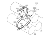
- the perspective view which expands and shows the A section of FIG.
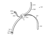
- the perspective view of the clip for wire harnesses of 1st Embodiment The perspective view which shows the structure of the wire harness of 2nd Embodiment.
- the wire harness 10 is routed in a path including the under floor of a vehicle 90 such as a hybrid vehicle or an electric vehicle, for example, and includes a motor 91 disposed in the front portion of the vehicle 90, a vehicle 90 is electrically connected to an inverter 92 disposed at the rear of the 90.
- a vehicle 90 such as a hybrid vehicle or an electric vehicle, for example, and includes a motor 91 disposed in the front portion of the vehicle 90, a vehicle 90 is electrically connected to an inverter 92 disposed at the rear of the 90.
- the wire harness 10 includes two electric wires 20, one route restricting member 30 that restricts the route of these electric wires 20, two electric wires 20, and one route restricting member 30. And a clip 40 for holding each. Note that a plurality of clips 40 are provided at intervals in the routing path of the wire harness 10.
- the electric wire 20 includes a core wire and a cylindrical insulating coating (both not shown) covering the outer periphery of the concentric wire.
- the core wire is a stranded wire formed by twisting together a plurality of metal strands made of, for example, a copper alloy.
- the insulating coating is an insulator such as polyvinyl chloride (PVC).
- the path regulating member 30 has higher rigidity than the electric wire 20, and is provided along the length direction of the electric wire 20.
- the path regulating member 30 is a round bar made of a metal material such as an aluminum alloy.
- the cross-sectional area of the cross section orthogonal to the length direction of the path regulating member 30 is substantially the same as the cross-sectional area of the cross section orthogonal to the length direction of the electric wire 20.
- the clip 40 includes a first holding unit 50 including two cylindrical accommodating portions (a first accommodating portion 51 and a second accommodating portion 52) that accommodate portions of the two electric wires 20 that extend in parallel with each other, and a first holding portion 50.
- a second holding portion 60 is provided that is connected to the holding portion 50 and holds a portion adjacent to the first holding portion 50 in one path regulating member 30.
- the clip 40 is integrally formed of a resin material such as polypropylene (PP).
- the 1st accommodating part 51 has a pair of side wall 53a, 53b which makes
- the second housing portion 52 has a pair of side walls 54a and 54b that form a halved cylindrical shape.
- the side walls 53a and 54a connected to one side of the hinge part 57 and the side walls 53b and 54b connected to the other side can be opened and closed with the hinge part 57 as a fulcrum.
- the other end in the circumferential direction of the side wall 54a of one side (the upper side in FIGS. 2 and 3) of the second storage part 52 (the end opposite to the end connected to the outer peripheral part of the side wall 53a of the first storage part 51) Part) is provided with a pair of arch parts 58 projecting from the edge part 56a of the side wall 54a along the circumferential direction at intervals in the axial direction of the second housing part 52.
- Each arch portion 58 has an engagement hole 58a.
- a first receiving recess 58b is provided in a portion of the outer peripheral surface of the side wall 54a that is continuous with each arch portion 58.
- a pair of second housing recesses 59 are provided on the outer peripheral surface of the end portion at intervals from each other in the axial direction of the second housing portion 52.
- Each second receiving recess 59 is provided with an engaging claw 59a protruding from the edge 56b of the side wall 54b along the circumferential direction.
- Edges 55a and 55b on the other end (end located close to the second storage part 52) side of the side walls 53a and 53b of the first storage part 51 are brought into contact with each other, and the side walls of the second storage part 52
- the engaging claw 59a is engaged with the engaging hole 58a in a state in which the edge portions 56a and 56b on the other end (end portion positioned away from the first accommodating portion 51) side of 54a and 54b are in contact with each other.
- the arch portion 58 is accommodated in the second accommodating recess 59, and the engaging claw 59a is accommodated in the first accommodating recess 58b.
- the arch part 58 and the engaging claw 59a do not protrude outward from the outer peripheral surfaces of the side walls 54a and 54b.
- the second holding part 60 has a band part 61 that fastens the outer periphery of the path regulating member 30, and a locking part 64 that locks the band part 61 and can adjust the tightening degree by the band part 61.
- the band part 61 has a first band part 62 extending from the outer peripheral surface of the side wall 54 a of the second storage part 52, and a second band part 63 extending from the outer peripheral surface of the side wall 53 a of the first storage part 51.
- a plurality of locking grooves 63 a (so-called serrations) extending along the width direction of the second band part 63 are provided on the surface of the second band part 63 at intervals in the length direction of the second band part 63. ing.
- the locking part 64 is provided at the tip of the first band part 62.
- the locking part 64 has an insertion port 64a through which the second band part 63 can be inserted.
- a locking claw (not shown) that is locked in the locking groove 63a of the second band portion 63 is provided on the inner surface of the insertion port 64a. The degree of tightening of the path regulating member 30 by the band part 61 can be adjusted according to the degree of insertion of the second band part 63 with respect to the locking part 64.
- the clip 40 includes a first holding unit 50 that holds the electric wire 20, and a second holding unit 60 that is connected to the first holding unit 50 and holds the path regulating member 30.
- the electric wire 20 is held by the first holding portion 50 of the clip 40, and the path regulating member 30 is held by the second holding portion 60. Moreover, the 1st holding
- the first holding unit 50 includes two cylindrical first housing parts 51 and second housing parts 52 that house the electric wires 20.
- Each accommodating part 51 (52) has side walls 53a and 53b (54a and 54b) that can be opened and closed.
- the outer peripheral parts of the side walls 53a, 53b, 54a, 54b of the adjacent accommodating parts 51, 52 are connected to each other.
- the electric wire 20 since the electric wire 20 is accommodated in the cylindrical first accommodating portion 51 and the second accommodating portion 52, the electric wire 20 having a circular cross section can be stably held. Moreover, it has the side wall 53a, 53b, 54a, 54b which the 1st accommodating part 51 and the 2nd accommodating part 52 can open and close. For this reason, the clip 40 can be easily attached to and detached from the electric wire 20 through the gaps between the edges 55a, 55b, 56a, and 56b of the side walls 53a, 53b, 54a, and 54b facing each other. Moreover, the attachment position of the clip 40 can be changed easily.
- the second holding part 60 has a band part 61 that fastens the outer periphery of the path regulating member 30, and a locking part 64 that locks the band part 61 and can adjust the tightening degree by the band part 61. Yes.
- the path regulating member 30 is fastened by the band part 61 of the second holding part 60.
- the tightening degree by the band part 61 can be adjusted by the locking part 64, the path regulation member 30 can be stably held by adjusting the tightening degree according to the shape of the path regulation member 30. .
- the wire harness 10 has a wire 20, a route restriction member 30 that has higher rigidity than the wire 20 and restricts the route of the wire 20 by fixing the wire 20 along the wire 20, and the clip 40. .
- Second Embodiment With reference to FIG.4 and FIG.5, 2nd Embodiment of the clip for wire harnesses and a wire harness is described.
- the same components as those in the first embodiment are denoted by the same reference numerals, and the components corresponding to those in the first embodiment are represented by “100” or “100” in the reference symbol “**” in the first embodiment.
- the components corresponding to those in the first embodiment are represented by “100” or “100” in the reference symbol “**” in the first embodiment.
- the wire harness 110 includes two electric wires 20, one route restricting member 30, and clips 140 that respectively hold the two electric wires 20 and one route restricting member 30.
- the clip 140 connects the first holding unit 160 that holds the two electric wires 20, the second holding unit 260 that holds the one path regulating member 30, and the first holding unit 160 and the second holding unit 260. Connecting portion 70 to be connected.
- the first holding part 160 has a band part 161 that fastens the outer periphery of the electric wire 20 and a locking part 164 that locks the band part 161 and can adjust the tightening degree by the band part 161.
- the first band portion 162 and the second band portion 163 of the band portion 161 extend from the connecting portion 70.
- the second holding part 260 has a band part 261 that tightens the outer periphery of the path regulating member 30, and a locking part 264 that locks the band part 261 and can adjust the tightening degree by the band part 261.
- the first band part 262 and the second band part 263 of the band part 261 extend from the connecting part 70.
- the total extension of the first band unit 162 and the second band unit 163 constituting the first holding unit 160 is the first band unit 262 and the second band unit 263 constituting the second holding unit 260. Has been longer than the total extension.
- the first holding portion 160 of the clip 140 includes a band portion 161 that tightens the outer periphery of the electric wire 20, and a locking portion 164 that locks the band portion 161 and can adjust the tightening degree by the band portion 161.
- the second holding part 260 includes a band part 261 that tightens the outer periphery of the path regulating member 30, and a locking part 264 that locks the band part 261 and can adjust the tightening degree by the band part 261.
- the electric wire 20 and the path regulating member 30 are tightened by the band portions 161 and 261, respectively. Further, the fastening degree of the electric wire 20 and the path regulating member 30 by the band parts 161 and 261 can be adjusted by the locking parts 164 and 264, respectively. For this reason, the electric wire 20 and the path
- the wire harness 110 includes the electric wire 20, a route restriction member 30 that restricts the route of the electric wire 20 by fixing the electric wire 20 along the electric wire 20, and the clip 140. .
- the operational effect according to the operational effect (5) can be achieved.
- This embodiment can be implemented with the following modifications.
- the present embodiment and the following modifications can be implemented in combination with each other within a technically consistent range.
- the first band portions 162 and 262 can be omitted. Such changes can also be applied to the first holding unit 50 of the first embodiment.
- a plurality of band parts 161 may be provided.
- the relative displacement of electric wires can be suppressed.
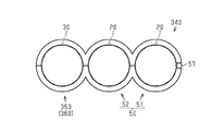
- a third storage portion 353 adjacent to the second storage portion 52 is provided, and the third storage portion What is necessary is just to let 353 be the 2nd holding
- locking part 64 are omissible.
- the arch portion 58 having the engagement hole 58a and the second accommodation recess 59 having the engagement claw 59a may be provided.
- the cross-sectional shape of the 1st accommodating part 51 and the 2nd accommodating part 52 may not be circular shape, and polygonal shape may be sufficient as it.
- the path regulating member 30 is not limited to an aluminum alloy.
- the path regulating member can be formed of another metal material such as a copper alloy.
- route control member can also be formed with a resin material. In this case, what is necessary is just to mold into a predetermined shape along the wiring path of the wire harness in advance.
- the cross-sectional area of the cross section orthogonal to the length direction of the path regulating member 30 may not be substantially the same as the cross-sectional area of the cross section orthogonal to the length direction of the electric wire 20. In short, it is sufficient that the path regulating member 30 can regulate the path of the electric wire 20.
- the cross-sectional area of the cross section orthogonal to the length direction of the path restricting member 30 is greater than the cross sectional area of the cross section orthogonal to the length direction of the electric wire 20. It may be small.
- skid member can also be interposed between the 1st holding
- FIG. -The attachment posture of the clips 40 and 140 is not particularly limited. In short, it is only necessary that the relative position of the path regulating member 30 with respect to the electric wire 20 can be maintained.
- band part 62,162,262 ... first band part, 63,163 , 263 ... second band part, 63a, 163a, 263a ... locking projection, 64, 164, 264 ... locking part, 64a, 164a, 264a ... insertion hole, 70 ... connecting part, 90 ... vehicle, 91 ... motor, 92
- the inverter, 353 ... third container portion.
Landscapes
- Engineering & Computer Science (AREA)
- General Engineering & Computer Science (AREA)
- Mechanical Engineering (AREA)
- Architecture (AREA)
- Civil Engineering (AREA)
- Structural Engineering (AREA)
- Clamps And Clips (AREA)
- Installation Of Indoor Wiring (AREA)
Abstract
Une poignée de faisceau électrique (40) comprend : une première partie de maintien (50) qui maintient un fil électrique (20) ; et une seconde partie de maintien (60) qui est reliée à la première partie de maintien (50) et maintient un élément de régulation de route (30).
Applications Claiming Priority (2)
| Application Number | Priority Date | Filing Date | Title |
|---|---|---|---|
| JP2018-042907 | 2018-03-09 | ||
| JP2018042907A JP7013954B2 (ja) | 2018-03-09 | 2018-03-09 | ワイヤハーネス用クリップ及びワイヤハーネス |
Publications (1)
| Publication Number | Publication Date |
|---|---|
| WO2019172019A1 true WO2019172019A1 (fr) | 2019-09-12 |
Family
ID=67845644
Family Applications (1)
| Application Number | Title | Priority Date | Filing Date |
|---|---|---|---|
| PCT/JP2019/007324 WO2019172019A1 (fr) | 2018-03-09 | 2019-02-26 | Poignée de faisceau électrique et faisceau électrique |
Country Status (2)
| Country | Link |
|---|---|
| JP (1) | JP7013954B2 (fr) |
| WO (1) | WO2019172019A1 (fr) |
Cited By (1)
| Publication number | Priority date | Publication date | Assignee | Title |
|---|---|---|---|---|
| CN111600241A (zh) * | 2020-05-30 | 2020-08-28 | 林浩敏 | 一种稳定走线的电缆电线走线机 |
Citations (3)
| Publication number | Priority date | Publication date | Assignee | Title |
|---|---|---|---|---|
| JPH01115089U (fr) * | 1988-01-29 | 1989-08-02 | ||
| JPH01143405U (fr) * | 1988-03-28 | 1989-10-02 | ||
| JP2004534187A (ja) * | 2001-06-21 | 2004-11-11 | ニューフレイ リミテッド ライアビリティ カンパニー | 少なくとも1つのラインを支持体に締結する保持クリップ |
Family Cites Families (5)
| Publication number | Priority date | Publication date | Assignee | Title |
|---|---|---|---|---|
| JP5479129B2 (ja) * | 2010-01-27 | 2014-04-23 | 株式会社フジクラ | ワイヤーハーネス |
| JP6180227B2 (ja) * | 2013-08-09 | 2017-08-16 | 矢崎総業株式会社 | 電線の固定部品 |
| JP6342176B2 (ja) * | 2014-02-14 | 2018-06-13 | 矢崎総業株式会社 | プロテクタ、プロテクタ連結システム、及びワイヤーハーネス |
| JP2016144288A (ja) * | 2015-01-30 | 2016-08-08 | 住友電装株式会社 | オプションコネクタ用固定具 |
| JP2017053372A (ja) * | 2015-09-07 | 2017-03-16 | 住友電装株式会社 | 結束バンド付配索具 |
-
2018
- 2018-03-09 JP JP2018042907A patent/JP7013954B2/ja active Active
-
2019
- 2019-02-26 WO PCT/JP2019/007324 patent/WO2019172019A1/fr active Application Filing
Patent Citations (3)
| Publication number | Priority date | Publication date | Assignee | Title |
|---|---|---|---|---|
| JPH01115089U (fr) * | 1988-01-29 | 1989-08-02 | ||
| JPH01143405U (fr) * | 1988-03-28 | 1989-10-02 | ||
| JP2004534187A (ja) * | 2001-06-21 | 2004-11-11 | ニューフレイ リミテッド ライアビリティ カンパニー | 少なくとも1つのラインを支持体に締結する保持クリップ |
Cited By (2)
| Publication number | Priority date | Publication date | Assignee | Title |
|---|---|---|---|---|
| CN111600241A (zh) * | 2020-05-30 | 2020-08-28 | 林浩敏 | 一种稳定走线的电缆电线走线机 |
| CN111600241B (zh) * | 2020-05-30 | 2021-07-23 | 泉州台商投资区沐鸿科技有限公司 | 一种稳定走线的电线走线机 |
Also Published As
| Publication number | Publication date |
|---|---|
| JP2019161775A (ja) | 2019-09-19 |
| JP7013954B2 (ja) | 2022-02-01 |
Similar Documents
| Publication | Publication Date | Title |
|---|---|---|
| JP4440223B2 (ja) | コルゲートチューブの固定構造 | |
| WO2014125665A1 (fr) | Structure de fixation de bande de serrage | |
| JP6015624B2 (ja) | コルゲートチューブへのバンドクリップ取付構造 | |
| JP6626070B2 (ja) | ワイヤハーネス | |
| WO2019172019A1 (fr) | Poignée de faisceau électrique et faisceau électrique | |
| JP3580201B2 (ja) | ワイヤハーネス用グロメット | |
| JP4358640B2 (ja) | 導線ホルダ | |
| WO2019172018A1 (fr) | Faisceau de fils | |
| WO2019181521A1 (fr) | Élément de restriction de trajet pour faisceau de fils, et faisceau de fils | |
| WO2019103030A1 (fr) | Dispositif de protection de faisceau de câblage et ensemble harnais | |
| JP2017079504A (ja) | ワイヤハーネス | |
| JP6873533B2 (ja) | 自動車ワイヤハーネス用のプロテクタ | |
| KR100580495B1 (ko) | 와이어 하니스의 결속용 밴드 케이블 | |
| JP6868457B2 (ja) | グロメット及びワイヤーハーネス | |
| US9825444B2 (en) | Electrical wire cover | |
| KR101872830B1 (ko) | 와이어 하네스 분리지그 | |
| JP7214526B2 (ja) | グロメットインナ及びグロメット | |
| JP2012182940A (ja) | バンドクリップ | |
| WO2022158302A1 (fr) | Faisceau de câbles | |
| JP7130376B2 (ja) | プロテクタおよびワイヤーハーネス | |
| JP7481210B2 (ja) | ボンダーキャップ | |
| JP7255470B2 (ja) | 配線部材の支持構造および配線部材 | |
| JP7359806B2 (ja) | プロテクタ、及び、ワイヤハーネス | |
| JP7469183B2 (ja) | ボンダーキャップ | |
| JP6822137B2 (ja) | 線状部品のプロテクタ構造 |
Legal Events
| Date | Code | Title | Description |
|---|---|---|---|
| 121 | Ep: the epo has been informed by wipo that ep was designated in this application |
Ref document number: 19763387 Country of ref document: EP Kind code of ref document: A1 |
|
| NENP | Non-entry into the national phase |
Ref country code: DE |
|
| 122 | Ep: pct application non-entry in european phase |
Ref document number: 19763387 Country of ref document: EP Kind code of ref document: A1 |