WO2019172019A1 - Wire harness grip and wire harness - Google Patents
Wire harness grip and wire harness Download PDFInfo
- Publication number
- WO2019172019A1 WO2019172019A1 PCT/JP2019/007324 JP2019007324W WO2019172019A1 WO 2019172019 A1 WO2019172019 A1 WO 2019172019A1 JP 2019007324 W JP2019007324 W JP 2019007324W WO 2019172019 A1 WO2019172019 A1 WO 2019172019A1
- Authority
- WO
- WIPO (PCT)
- Prior art keywords
- wire
- wire harness
- clip
- band
- holding
- Prior art date
Links
- 230000001105 regulatory effect Effects 0.000 claims description 49
- 230000002093 peripheral effect Effects 0.000 claims description 12
- 230000000694 effects Effects 0.000 description 9
- 238000012423 maintenance Methods 0.000 description 8
- 210000000078 claw Anatomy 0.000 description 7
- 230000001012 protector Effects 0.000 description 7
- 238000003780 insertion Methods 0.000 description 4
- 230000037431 insertion Effects 0.000 description 4
- 238000006073 displacement reaction Methods 0.000 description 3
- 229910000838 Al alloy Inorganic materials 0.000 description 2
- 229910000881 Cu alloy Inorganic materials 0.000 description 2
- 239000004743 Polypropylene Substances 0.000 description 2
- 239000011248 coating agent Substances 0.000 description 2
- 238000000576 coating method Methods 0.000 description 2
- 239000000463 material Substances 0.000 description 2
- 239000007769 metal material Substances 0.000 description 2
- 238000012986 modification Methods 0.000 description 2
- 230000004048 modification Effects 0.000 description 2
- 229920001155 polypropylene Polymers 0.000 description 2
- 239000011347 resin Substances 0.000 description 2
- 229920005989 resin Polymers 0.000 description 2
- 230000004308 accommodation Effects 0.000 description 1
- 229910052782 aluminium Inorganic materials 0.000 description 1
- XAGFODPZIPBFFR-UHFFFAOYSA-N aluminium Chemical compound [Al] XAGFODPZIPBFFR-UHFFFAOYSA-N 0.000 description 1
- 239000012212 insulator Substances 0.000 description 1
- 229910052751 metal Inorganic materials 0.000 description 1
- 239000002184 metal Substances 0.000 description 1
- -1 polypropylene Polymers 0.000 description 1
- 239000004800 polyvinyl chloride Substances 0.000 description 1
Images


Classifications
-
- F—MECHANICAL ENGINEERING; LIGHTING; HEATING; WEAPONS; BLASTING
- F16—ENGINEERING ELEMENTS AND UNITS; GENERAL MEASURES FOR PRODUCING AND MAINTAINING EFFECTIVE FUNCTIONING OF MACHINES OR INSTALLATIONS; THERMAL INSULATION IN GENERAL
- F16B—DEVICES FOR FASTENING OR SECURING CONSTRUCTIONAL ELEMENTS OR MACHINE PARTS TOGETHER, e.g. NAILS, BOLTS, CIRCLIPS, CLAMPS, CLIPS OR WEDGES; JOINTS OR JOINTING
- F16B2/00—Friction-grip releasable fastenings
- F16B2/02—Clamps, i.e. with gripping action effected by positive means other than the inherent resistance to deformation of the material of the fastening
- F16B2/06—Clamps, i.e. with gripping action effected by positive means other than the inherent resistance to deformation of the material of the fastening external, i.e. with contracting action
- F16B2/08—Clamps, i.e. with gripping action effected by positive means other than the inherent resistance to deformation of the material of the fastening external, i.e. with contracting action using bands
-
- F—MECHANICAL ENGINEERING; LIGHTING; HEATING; WEAPONS; BLASTING
- F16—ENGINEERING ELEMENTS AND UNITS; GENERAL MEASURES FOR PRODUCING AND MAINTAINING EFFECTIVE FUNCTIONING OF MACHINES OR INSTALLATIONS; THERMAL INSULATION IN GENERAL
- F16B—DEVICES FOR FASTENING OR SECURING CONSTRUCTIONAL ELEMENTS OR MACHINE PARTS TOGETHER, e.g. NAILS, BOLTS, CIRCLIPS, CLAMPS, CLIPS OR WEDGES; JOINTS OR JOINTING
- F16B2/00—Friction-grip releasable fastenings
- F16B2/20—Clips, i.e. with gripping action effected solely by the inherent resistance to deformation of the material of the fastening
-
- H—ELECTRICITY
- H02—GENERATION; CONVERSION OR DISTRIBUTION OF ELECTRIC POWER
- H02G—INSTALLATION OF ELECTRIC CABLES OR LINES, OR OF COMBINED OPTICAL AND ELECTRIC CABLES OR LINES
- H02G3/00—Installations of electric cables or lines or protective tubing therefor in or on buildings, equivalent structures or vehicles
- H02G3/30—Installations of cables or lines on walls, floors or ceilings
Definitions
- the present invention relates to a wire harness clip and a wire harness.
- a vehicle is provided with a protector for routing a wire harness along a predetermined routing route (see, for example, Patent Document 1).
- the protector of the literature 1 is provided with a protector body having a recess that can accommodate an electric wire, and a lid member that closes the opening of the recess.
- a protector having a shape corresponding to a predetermined routing route the route of the wire harness accommodated in the protector is regulated.
- the electric wire and the path regulating member are adhered to each other in a state where the electric wire is placed along a rod-like path regulating member (also called a splint) made of aluminum or the like bent along a predetermined wiring path.
- a rod-like path regulating member also called a splint
- fasteners fastened with tape Some have fasteners fastened with tape.
- a plurality of fastening portions are provided at intervals in the length direction of the path regulating member.
- the electric wire and the path regulating member can be fastened at each fastening part, but the path regulating member is easily twisted between the fastening parts, and the wire There is a possibility that the harness is displaced from the predetermined route.
- An object of the present invention is to provide a wire harness clip and a wire harness that can regulate a routing route with a simple configuration.
- a clip for a wire harness for achieving the above object includes an electric wire and a path regulating member that has a higher rigidity than the electric wire and regulates the path of the electric wire by fixing the electric wire along the electric wire.
- a clip for a wire harness applied to a harness comprising: a first holding part that holds the electric wire; and a second holding part that is connected to the first holding part and holds the path regulating member. Yes.
- the electric wire is held by the first holding unit, and the path regulating member is held by the second holding unit.
- maintenance part is mutually connected. Therefore, if the clip is attached to a portion where the twist of the path regulating member may occur in the wiring route of the wire harness, the path regulating member with respect to the electric wire in the circumferential direction centering on the axis of the electric wire. Can be prevented from relative displacement. Thereby, it can suppress that a wire harness shifts
- the first holding portion includes a cylindrical accommodating portion that accommodates the electric wire, and the accommodating portion has a side wall that can be opened and closed. According to this configuration, since the electric wire is accommodated in the cylindrical accommodating portion, the electric wire can be stably held. Moreover, since the accommodating part has the side wall which can be opened and closed, a clip can be easily attached or detached with respect to an electric wire through the clearance gap between the edge parts which the side walls mutually oppose. Moreover, the attachment position of a clip can be changed easily.
- the first holding portion includes a plurality of the accommodating portions, and the outer peripheral portions of the side walls of the adjacent accommodating portions are connected to each other.
- the first holding unit includes a plurality of housing units, the plurality of electric wires can be stably held by the first holding unit.
- the second holding portion includes: a band portion that tightens an outer periphery of the path regulating member; and a locking portion that locks the band portion and can adjust a tightening degree by the band portion. It is preferable to have.
- the path regulating member is tightened by the band part of the second holding part. Further, since the tightening degree by the band part can be adjusted by the locking part, the path regulating member can be stably held by adjusting the tightening degree according to the shape of the path regulating member.
- both of the first holding portion and the second holding portion are a band portion that tightens an outer periphery of the electric wire or the path regulating member, and a band portion that locks the band portion and is tightened by the band portion. It is preferable to have an engaging portion that can adjust the degree.
- the electric wire and the path regulating member are each tightened by the band portion.
- route control member by a band part can each be adjusted with a latching
- route control member can be stably hold
- a wire harness for achieving the above object includes an electric wire, a path regulating member that has a higher rigidity than the electric wire, and regulates the path of the electric wire by fixing the electric wire along the wire, And a wire harness clip.
- the wiring route of the wire harness can be regulated with a simple configuration.
- the side view which shows the wire harness of the state wired by the vehicle about 1st Embodiment of the clip for wire harnesses, and a wire harness.
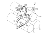
- the perspective view which expands and shows the A section of FIG.
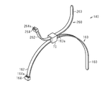
- the perspective view of the clip for wire harnesses of 1st Embodiment The perspective view which shows the structure of the wire harness of 2nd Embodiment.
- the wire harness 10 is routed in a path including the under floor of a vehicle 90 such as a hybrid vehicle or an electric vehicle, for example, and includes a motor 91 disposed in the front portion of the vehicle 90, a vehicle 90 is electrically connected to an inverter 92 disposed at the rear of the 90.
- a vehicle 90 such as a hybrid vehicle or an electric vehicle, for example, and includes a motor 91 disposed in the front portion of the vehicle 90, a vehicle 90 is electrically connected to an inverter 92 disposed at the rear of the 90.
- the wire harness 10 includes two electric wires 20, one route restricting member 30 that restricts the route of these electric wires 20, two electric wires 20, and one route restricting member 30. And a clip 40 for holding each. Note that a plurality of clips 40 are provided at intervals in the routing path of the wire harness 10.
- the electric wire 20 includes a core wire and a cylindrical insulating coating (both not shown) covering the outer periphery of the concentric wire.
- the core wire is a stranded wire formed by twisting together a plurality of metal strands made of, for example, a copper alloy.
- the insulating coating is an insulator such as polyvinyl chloride (PVC).
- the path regulating member 30 has higher rigidity than the electric wire 20, and is provided along the length direction of the electric wire 20.
- the path regulating member 30 is a round bar made of a metal material such as an aluminum alloy.
- the cross-sectional area of the cross section orthogonal to the length direction of the path regulating member 30 is substantially the same as the cross-sectional area of the cross section orthogonal to the length direction of the electric wire 20.
- the clip 40 includes a first holding unit 50 including two cylindrical accommodating portions (a first accommodating portion 51 and a second accommodating portion 52) that accommodate portions of the two electric wires 20 that extend in parallel with each other, and a first holding portion 50.
- a second holding portion 60 is provided that is connected to the holding portion 50 and holds a portion adjacent to the first holding portion 50 in one path regulating member 30.
- the clip 40 is integrally formed of a resin material such as polypropylene (PP).
- the 1st accommodating part 51 has a pair of side wall 53a, 53b which makes
- the second housing portion 52 has a pair of side walls 54a and 54b that form a halved cylindrical shape.
- the side walls 53a and 54a connected to one side of the hinge part 57 and the side walls 53b and 54b connected to the other side can be opened and closed with the hinge part 57 as a fulcrum.
- the other end in the circumferential direction of the side wall 54a of one side (the upper side in FIGS. 2 and 3) of the second storage part 52 (the end opposite to the end connected to the outer peripheral part of the side wall 53a of the first storage part 51) Part) is provided with a pair of arch parts 58 projecting from the edge part 56a of the side wall 54a along the circumferential direction at intervals in the axial direction of the second housing part 52.
- Each arch portion 58 has an engagement hole 58a.
- a first receiving recess 58b is provided in a portion of the outer peripheral surface of the side wall 54a that is continuous with each arch portion 58.
- a pair of second housing recesses 59 are provided on the outer peripheral surface of the end portion at intervals from each other in the axial direction of the second housing portion 52.
- Each second receiving recess 59 is provided with an engaging claw 59a protruding from the edge 56b of the side wall 54b along the circumferential direction.
- Edges 55a and 55b on the other end (end located close to the second storage part 52) side of the side walls 53a and 53b of the first storage part 51 are brought into contact with each other, and the side walls of the second storage part 52
- the engaging claw 59a is engaged with the engaging hole 58a in a state in which the edge portions 56a and 56b on the other end (end portion positioned away from the first accommodating portion 51) side of 54a and 54b are in contact with each other.
- the arch portion 58 is accommodated in the second accommodating recess 59, and the engaging claw 59a is accommodated in the first accommodating recess 58b.
- the arch part 58 and the engaging claw 59a do not protrude outward from the outer peripheral surfaces of the side walls 54a and 54b.
- the second holding part 60 has a band part 61 that fastens the outer periphery of the path regulating member 30, and a locking part 64 that locks the band part 61 and can adjust the tightening degree by the band part 61.
- the band part 61 has a first band part 62 extending from the outer peripheral surface of the side wall 54 a of the second storage part 52, and a second band part 63 extending from the outer peripheral surface of the side wall 53 a of the first storage part 51.
- a plurality of locking grooves 63 a (so-called serrations) extending along the width direction of the second band part 63 are provided on the surface of the second band part 63 at intervals in the length direction of the second band part 63. ing.
- the locking part 64 is provided at the tip of the first band part 62.
- the locking part 64 has an insertion port 64a through which the second band part 63 can be inserted.
- a locking claw (not shown) that is locked in the locking groove 63a of the second band portion 63 is provided on the inner surface of the insertion port 64a. The degree of tightening of the path regulating member 30 by the band part 61 can be adjusted according to the degree of insertion of the second band part 63 with respect to the locking part 64.
- the clip 40 includes a first holding unit 50 that holds the electric wire 20, and a second holding unit 60 that is connected to the first holding unit 50 and holds the path regulating member 30.
- the electric wire 20 is held by the first holding portion 50 of the clip 40, and the path regulating member 30 is held by the second holding portion 60. Moreover, the 1st holding
- the first holding unit 50 includes two cylindrical first housing parts 51 and second housing parts 52 that house the electric wires 20.
- Each accommodating part 51 (52) has side walls 53a and 53b (54a and 54b) that can be opened and closed.
- the outer peripheral parts of the side walls 53a, 53b, 54a, 54b of the adjacent accommodating parts 51, 52 are connected to each other.
- the electric wire 20 since the electric wire 20 is accommodated in the cylindrical first accommodating portion 51 and the second accommodating portion 52, the electric wire 20 having a circular cross section can be stably held. Moreover, it has the side wall 53a, 53b, 54a, 54b which the 1st accommodating part 51 and the 2nd accommodating part 52 can open and close. For this reason, the clip 40 can be easily attached to and detached from the electric wire 20 through the gaps between the edges 55a, 55b, 56a, and 56b of the side walls 53a, 53b, 54a, and 54b facing each other. Moreover, the attachment position of the clip 40 can be changed easily.
- the second holding part 60 has a band part 61 that fastens the outer periphery of the path regulating member 30, and a locking part 64 that locks the band part 61 and can adjust the tightening degree by the band part 61. Yes.
- the path regulating member 30 is fastened by the band part 61 of the second holding part 60.
- the tightening degree by the band part 61 can be adjusted by the locking part 64, the path regulation member 30 can be stably held by adjusting the tightening degree according to the shape of the path regulation member 30. .
- the wire harness 10 has a wire 20, a route restriction member 30 that has higher rigidity than the wire 20 and restricts the route of the wire 20 by fixing the wire 20 along the wire 20, and the clip 40. .
- Second Embodiment With reference to FIG.4 and FIG.5, 2nd Embodiment of the clip for wire harnesses and a wire harness is described.
- the same components as those in the first embodiment are denoted by the same reference numerals, and the components corresponding to those in the first embodiment are represented by “100” or “100” in the reference symbol “**” in the first embodiment.
- the components corresponding to those in the first embodiment are represented by “100” or “100” in the reference symbol “**” in the first embodiment.
- the wire harness 110 includes two electric wires 20, one route restricting member 30, and clips 140 that respectively hold the two electric wires 20 and one route restricting member 30.
- the clip 140 connects the first holding unit 160 that holds the two electric wires 20, the second holding unit 260 that holds the one path regulating member 30, and the first holding unit 160 and the second holding unit 260. Connecting portion 70 to be connected.
- the first holding part 160 has a band part 161 that fastens the outer periphery of the electric wire 20 and a locking part 164 that locks the band part 161 and can adjust the tightening degree by the band part 161.
- the first band portion 162 and the second band portion 163 of the band portion 161 extend from the connecting portion 70.
- the second holding part 260 has a band part 261 that tightens the outer periphery of the path regulating member 30, and a locking part 264 that locks the band part 261 and can adjust the tightening degree by the band part 261.
- the first band part 262 and the second band part 263 of the band part 261 extend from the connecting part 70.
- the total extension of the first band unit 162 and the second band unit 163 constituting the first holding unit 160 is the first band unit 262 and the second band unit 263 constituting the second holding unit 260. Has been longer than the total extension.
- the first holding portion 160 of the clip 140 includes a band portion 161 that tightens the outer periphery of the electric wire 20, and a locking portion 164 that locks the band portion 161 and can adjust the tightening degree by the band portion 161.
- the second holding part 260 includes a band part 261 that tightens the outer periphery of the path regulating member 30, and a locking part 264 that locks the band part 261 and can adjust the tightening degree by the band part 261.
- the electric wire 20 and the path regulating member 30 are tightened by the band portions 161 and 261, respectively. Further, the fastening degree of the electric wire 20 and the path regulating member 30 by the band parts 161 and 261 can be adjusted by the locking parts 164 and 264, respectively. For this reason, the electric wire 20 and the path
- the wire harness 110 includes the electric wire 20, a route restriction member 30 that restricts the route of the electric wire 20 by fixing the electric wire 20 along the electric wire 20, and the clip 140. .
- the operational effect according to the operational effect (5) can be achieved.
- This embodiment can be implemented with the following modifications.
- the present embodiment and the following modifications can be implemented in combination with each other within a technically consistent range.
- the first band portions 162 and 262 can be omitted. Such changes can also be applied to the first holding unit 50 of the first embodiment.
- a plurality of band parts 161 may be provided.
- the relative displacement of electric wires can be suppressed.
- a third storage portion 353 adjacent to the second storage portion 52 is provided, and the third storage portion What is necessary is just to let 353 be the 2nd holding
- locking part 64 are omissible.
- the arch portion 58 having the engagement hole 58a and the second accommodation recess 59 having the engagement claw 59a may be provided.
- the cross-sectional shape of the 1st accommodating part 51 and the 2nd accommodating part 52 may not be circular shape, and polygonal shape may be sufficient as it.
- the path regulating member 30 is not limited to an aluminum alloy.
- the path regulating member can be formed of another metal material such as a copper alloy.
- route control member can also be formed with a resin material. In this case, what is necessary is just to mold into a predetermined shape along the wiring path of the wire harness in advance.
- the cross-sectional area of the cross section orthogonal to the length direction of the path regulating member 30 may not be substantially the same as the cross-sectional area of the cross section orthogonal to the length direction of the electric wire 20. In short, it is sufficient that the path regulating member 30 can regulate the path of the electric wire 20.
- the cross-sectional area of the cross section orthogonal to the length direction of the path restricting member 30 is greater than the cross sectional area of the cross section orthogonal to the length direction of the electric wire 20. It may be small.
- skid member can also be interposed between the 1st holding
- FIG. -The attachment posture of the clips 40 and 140 is not particularly limited. In short, it is only necessary that the relative position of the path regulating member 30 with respect to the electric wire 20 can be maintained.
- band part 62,162,262 ... first band part, 63,163 , 263 ... second band part, 63a, 163a, 263a ... locking projection, 64, 164, 264 ... locking part, 64a, 164a, 264a ... insertion hole, 70 ... connecting part, 90 ... vehicle, 91 ... motor, 92
- the inverter, 353 ... third container portion.
Abstract
A wire harness grip (40) that comprises: a first holding part (50) that holds an electric wire (20); and a second holding part (60) that is connected to the first holding part (50) and holds a route regulation member (30).
Description
本発明は、ワイヤハーネス用クリップ及びワイヤハーネスに関する。
The present invention relates to a wire harness clip and a wire harness.
従来、車両には、所定の配索経路に沿ってワイヤハーネスを配索するためのプロテクタが設けられている(例えば、特許文献1参照)。同文献1のプロテクタは、電線を収容可能な凹部を有するプロテクタ本体と、凹部の開口を閉塞する蓋部材とを備えている。所定の配索経路に対応した形状のプロテクタを用いることにより、プロテクタ内に収容されたワイヤハーネスの経路が規制される。
Conventionally, a vehicle is provided with a protector for routing a wire harness along a predetermined routing route (see, for example, Patent Document 1). The protector of the literature 1 is provided with a protector body having a recess that can accommodate an electric wire, and a lid member that closes the opening of the recess. By using a protector having a shape corresponding to a predetermined routing route, the route of the wire harness accommodated in the protector is regulated.
また、ワイヤハーネスにおいては、所定の配索経路に沿って曲げられたアルミニウムなどからなる棒状の経路規制部材(添え木とも称される)に電線を沿わせた状態でこれら電線及び経路規制部材が粘着テープにより留められた留め部を備えたものがある。こうしたワイヤハーネスでは、経路規制部材の長さ方向において複数の留め部が互いに間隔をおいて設けられている。
In addition, in the wire harness, the electric wire and the path regulating member are adhered to each other in a state where the electric wire is placed along a rod-like path regulating member (also called a splint) made of aluminum or the like bent along a predetermined wiring path. Some have fasteners fastened with tape. In such a wire harness, a plurality of fastening portions are provided at intervals in the length direction of the path regulating member.
ところで、特許文献1に記載のワイヤハーネスにおいては、ワイヤハーネスの配索経路上にプロテクタが設けられることで、ワイヤハーネス周辺のスペースが必要となったり、ワイヤハーネスを車両に取り付ける際の作業が煩雑になったりするおそれがある。さらに、ワイヤハーネスの配索経路が変更になった場合には、プロテクタの形状を変更する必要がある。
By the way, in the wire harness of patent document 1, since the protector is provided on the wiring path of the wire harness, a space around the wire harness is required, or the work for attaching the wire harness to the vehicle is complicated. There is a risk of becoming. Furthermore, when the wiring route of the wire harness is changed, it is necessary to change the shape of the protector.
また、上述した経路規制部材を備えるワイヤハーネスの場合、各留め部においては電線と経路規制部材とを留めることができるものの、留め部同士の間においては、経路規制部材にねじれが生じやすく、ワイヤハーネスが所定の配索経路からずれるおそれがある。
Further, in the case of the wire harness provided with the above-described path regulating member, the electric wire and the path regulating member can be fastened at each fastening part, but the path regulating member is easily twisted between the fastening parts, and the wire There is a possibility that the harness is displaced from the predetermined route.
本発明の目的は、簡易な構成により配索経路を規制できるワイヤハーネス用クリップ及びワイヤハーネスを提供することにある。
An object of the present invention is to provide a wire harness clip and a wire harness that can regulate a routing route with a simple configuration.
上記目的を達成するためのワイヤハーネス用クリップは、電線と、前記電線よりも高い剛性を有し、前記電線を沿わせて固定することで前記電線の経路を規制する経路規制部材とを備えるワイヤハーネスに適用されるワイヤハーネス用クリップであって、前記電線を保持する第1保持部と、前記第1保持部に連結されるとともに前記経路規制部材を保持する第2保持部と、を備えている。
A clip for a wire harness for achieving the above object includes an electric wire and a path regulating member that has a higher rigidity than the electric wire and regulates the path of the electric wire by fixing the electric wire along the electric wire. A clip for a wire harness applied to a harness, comprising: a first holding part that holds the electric wire; and a second holding part that is connected to the first holding part and holds the path regulating member. Yes.
同構成によれば、電線が第1保持部により保持されるとともに、経路規制部材が第2保持部により保持される。また、各保持部は互いに連結されている。このため、ワイヤハーネスの配索経路において経路規制部材のねじれが生じるおそれのある部分に対して上記クリップを取り付けるようにすれば、電線の軸線を中心とした周方向において電線に対して経路規制部材が相対変位することを抑制できる。これにより、ワイヤハーネスが所定の配索経路からずれることを抑制できる。したがって、簡単な構成によりワイヤハーネスの配索経路を規制することができる。
According to the same configuration, the electric wire is held by the first holding unit, and the path regulating member is held by the second holding unit. Moreover, each holding | maintenance part is mutually connected. Therefore, if the clip is attached to a portion where the twist of the path regulating member may occur in the wiring route of the wire harness, the path regulating member with respect to the electric wire in the circumferential direction centering on the axis of the electric wire. Can be prevented from relative displacement. Thereby, it can suppress that a wire harness shifts | deviates from a predetermined wiring path | route. Therefore, the wiring route of the wire harness can be regulated with a simple configuration.
上記ワイヤハーネス用クリップにおいて、前記第1保持部は、前記電線を収容する筒状の収容部を備えており、前記収容部は、開閉可能な側壁を有していることが好ましい。
同構成によれば、筒状の収容部に電線が収容されるため、電線を安定して保持することができる。また、収容部が開閉可能な側壁を有しているため、側壁の互いに対向する縁部同士の間の隙間を通じて電線に対してクリップを容易に着脱することができる。また、クリップの取り付け位置を容易に変更することができる。 In the wire harness clip, it is preferable that the first holding portion includes a cylindrical accommodating portion that accommodates the electric wire, and the accommodating portion has a side wall that can be opened and closed.
According to this configuration, since the electric wire is accommodated in the cylindrical accommodating portion, the electric wire can be stably held. Moreover, since the accommodating part has the side wall which can be opened and closed, a clip can be easily attached or detached with respect to an electric wire through the clearance gap between the edge parts which the side walls mutually oppose. Moreover, the attachment position of a clip can be changed easily.
上記ワイヤハーネス用クリップにおいて、前記第1保持部は、複数の前記収容部を備えており、隣り合う前記収容部の前記側壁の外周部同士が互いに連結されていることが好ましい。
In the wire harness clip, it is preferable that the first holding portion includes a plurality of the accommodating portions, and the outer peripheral portions of the side walls of the adjacent accommodating portions are connected to each other.
同構成によれば、第1保持部が複数の収容部を備えているため、第1保持部によって複数の電線を安定して保持することができる。
上記ワイヤハーネス用クリップにおいて、前記第2保持部は、前記経路規制部材の外周を締め付けるバンド部と、前記バンド部を係止するとともに前記バンド部による締め付け度合を調節可能な係止部と、を有していることが好ましい。 According to this configuration, since the first holding unit includes a plurality of housing units, the plurality of electric wires can be stably held by the first holding unit.
In the wire harness clip, the second holding portion includes: a band portion that tightens an outer periphery of the path regulating member; and a locking portion that locks the band portion and can adjust a tightening degree by the band portion. It is preferable to have.
同構成によれば、経路規制部材は第2保持部のバンド部により締め付けられることとなる。また、バンド部による締め付け度合が係止部により調節可能であるため、経路規制部材の形状に合わせて上記締め付け度合を調節することにより経路規制部材を安定して保持することができる。
According to this configuration, the path regulating member is tightened by the band part of the second holding part. Further, since the tightening degree by the band part can be adjusted by the locking part, the path regulating member can be stably held by adjusting the tightening degree according to the shape of the path regulating member.
上記ワイヤハーネス用クリップにおいて、前記第1保持部及び前記第2保持部の双方は、前記電線または前記経路規制部材の外周を締め付けるバンド部と、前記バンド部を係止するとともに前記バンド部による締め付け度合を調節可能な係止部と、を有していることが好ましい。
In the wire harness clip, both of the first holding portion and the second holding portion are a band portion that tightens an outer periphery of the electric wire or the path regulating member, and a band portion that locks the band portion and is tightened by the band portion. It is preferable to have an engaging portion that can adjust the degree.
同構成によれば、電線及び経路規制部材がそれぞれバンド部により締め付けられることとなる。また、バンド部による電線及び経路規制部材の締め付け度合が係止部によりそれぞれ調節可能である。このため、電線及び経路規制部材の形状に合わせて締め付け度合を各別に調節することにより電線及び経路規制部材を安定して保持することができる。したがって、複数本の電線が配索されている箇所にワイヤハーネス用クリップを取り付ける場合や、取り付け箇所によって経路規制部材の形状が異なる場合であっても、同一のワイヤハーネス用クリップを採用することができる。
According to the same configuration, the electric wire and the path regulating member are each tightened by the band portion. Moreover, the fastening degree of the electric wire and path | route control member by a band part can each be adjusted with a latching | locking part. For this reason, an electric wire and a path | route control member can be stably hold | maintained by adjusting a fastening degree separately according to the shape of an electric wire and a path | route control member. Therefore, even when the wire harness clip is attached to a place where a plurality of electric wires are routed, or even when the shape of the path regulating member differs depending on the attachment place, the same wire harness clip can be adopted. it can.
また、上記目的を達成するためのワイヤハーネスは、電線と、前記電線よりも高い剛性を有し、前記電線を沿わせて固定することで前記電線の経路を規制する経路規制部材と、上記いずれかのワイヤハーネス用クリップと、を備える。
Further, a wire harness for achieving the above object includes an electric wire, a path regulating member that has a higher rigidity than the electric wire, and regulates the path of the electric wire by fixing the electric wire along the wire, And a wire harness clip.
同構成によれば、上記ワイヤハーネス用クリップのいずれか1つの作用効果に準じた作用効果を奏することができる。
According to the same configuration, it is possible to achieve an operational effect according to any one of the operational effects of the wire harness clip.
本発明によれば、簡易な構成によりワイヤハーネスの配索経路を規制できる。
According to the present invention, the wiring route of the wire harness can be regulated with a simple configuration.
<第1実施形態>
以下、図1~図3を参照して、ワイヤハーネス用クリップ及びワイヤハーネスの第一実施形態について説明する。 <First Embodiment>
Hereinafter, a first embodiment of the wire harness clip and the wire harness will be described with reference to FIGS. 1 to 3.
以下、図1~図3を参照して、ワイヤハーネス用クリップ及びワイヤハーネスの第一実施形態について説明する。 <First Embodiment>
Hereinafter, a first embodiment of the wire harness clip and the wire harness will be described with reference to FIGS. 1 to 3.
図1に示すように、ワイヤハーネス10は、例えばハイブリッド車や電気自動車などの車両90の床下を含む経路に配索されるものであり、車両90の前部に配置されるモータ91と、車両90の後部に配置されるインバータ92とを電気的に接続する。
As shown in FIG. 1, the wire harness 10 is routed in a path including the under floor of a vehicle 90 such as a hybrid vehicle or an electric vehicle, for example, and includes a motor 91 disposed in the front portion of the vehicle 90, a vehicle 90 is electrically connected to an inverter 92 disposed at the rear of the 90.
図2に示すように、ワイヤハーネス10は、2本の電線20と、これら電線20の経路を規制する1本の経路規制部材30と、2本の電線20と1本の経路規制部材30とをそれぞれ保持するクリップ40とを備えている。なお、クリップ40は、ワイヤハーネス10の配索経路において互いに間隔をおいて複数設けられている。
As shown in FIG. 2, the wire harness 10 includes two electric wires 20, one route restricting member 30 that restricts the route of these electric wires 20, two electric wires 20, and one route restricting member 30. And a clip 40 for holding each. Note that a plurality of clips 40 are provided at intervals in the routing path of the wire harness 10.
電線20は、芯線と同芯線の外周を覆う円筒状の絶縁被覆(いずれも図示略)とを有している。芯線は、例えば、銅合金からなる複数の金属素線を撚り合わせて形成される撚り線である。絶縁被覆は、例えば、ポリ塩化ビニル(PVC)などの絶縁体である。
The electric wire 20 includes a core wire and a cylindrical insulating coating (both not shown) covering the outer periphery of the concentric wire. The core wire is a stranded wire formed by twisting together a plurality of metal strands made of, for example, a copper alloy. The insulating coating is an insulator such as polyvinyl chloride (PVC).
経路規制部材30は、電線20よりも高い剛性を有しており、電線20の長さ方向に沿って設けられている。経路規制部材30は、例えばアルミニウム合金などの金属材料からなる丸棒である。経路規制部材30の長さ方向に直交する断面の断面積は、電線20の長さ方向に直交する断面の断面積と略同一である。
The path regulating member 30 has higher rigidity than the electric wire 20, and is provided along the length direction of the electric wire 20. The path regulating member 30 is a round bar made of a metal material such as an aluminum alloy. The cross-sectional area of the cross section orthogonal to the length direction of the path regulating member 30 is substantially the same as the cross-sectional area of the cross section orthogonal to the length direction of the electric wire 20.
クリップ40は、2本の電線20の互いに平行に延びる部分を収容する円筒状の2つの収容部(第1収容部51及び第2収容部52)を備えた第1保持部50と、第1保持部50に連結されるとともに1本の経路規制部材30のうち第1保持部50と隣り合う部分を保持する第2保持部60とを備えている。クリップ40は、例えばポリプロピレン(PP)などの樹脂材料により一体成形されている。
The clip 40 includes a first holding unit 50 including two cylindrical accommodating portions (a first accommodating portion 51 and a second accommodating portion 52) that accommodate portions of the two electric wires 20 that extend in parallel with each other, and a first holding portion 50. A second holding portion 60 is provided that is connected to the holding portion 50 and holds a portion adjacent to the first holding portion 50 in one path regulating member 30. The clip 40 is integrally formed of a resin material such as polypropylene (PP).
<第1保持部50>
図2及び図3に示すように、第1収容部51は、半割円筒状をなす一対の側壁53a,53bを有している。これら側壁53a,53bの周方向における一端は、ヒンジ部57を介して連結されている。 <First holding unit 50>
As shown in FIG.2 and FIG.3, the1st accommodating part 51 has a pair of side wall 53a, 53b which makes | forms a half cylinder shape. One end in the circumferential direction of these side walls 53a, 53b is connected via a hinge portion 57.
図2及び図3に示すように、第1収容部51は、半割円筒状をなす一対の側壁53a,53bを有している。これら側壁53a,53bの周方向における一端は、ヒンジ部57を介して連結されている。 <
As shown in FIG.2 and FIG.3, the
第2収容部52は、半割円筒状をなす一対の側壁54a,54bを有している。側壁54a,54bの周方向における一端(第1収容部51に近接して位置する端部)側の外周部と、側壁54a,54bに隣り合う第1収容部51の周方向における他端(第2収容部52に近接して位置する端部)側の外周部とが連結されている。
The second housing portion 52 has a pair of side walls 54a and 54b that form a halved cylindrical shape. The outer peripheral portion on the side of one end in the circumferential direction of the side walls 54a, 54b (the end portion located close to the first housing portion 51) and the other end in the circumferential direction of the first housing portion 51 adjacent to the side walls 54a, 54b (first 2 is connected to the outer peripheral part on the side of the end part located close to the accommodating part 52.
したがって、ヒンジ部57の一方に連なる側壁53a,54aと他方に連なる側壁53b,54bとは、ヒンジ部57を支点として開閉可能である。
第2収容部52の一方(図2及び図3の上側)の側壁54aの周方向における他端部(第1収容部51の側壁53aの外周部に連結された端部とは反対側の端部)には、周方向に沿って側壁54aの縁部56aから突出する一対のアーチ部58が、第2収容部52の軸線方向において互いに間隔をおいて設けられている。各アーチ部58は、係合孔58aを有している。側壁54aの外周面のうち各アーチ部58に連なる部分には、第1収容凹部58bが設けられている。 Therefore, the side walls 53a and 54a connected to one side of the hinge part 57 and the side walls 53b and 54b connected to the other side can be opened and closed with the hinge part 57 as a fulcrum.
The other end in the circumferential direction of theside wall 54a of one side (the upper side in FIGS. 2 and 3) of the second storage part 52 (the end opposite to the end connected to the outer peripheral part of the side wall 53a of the first storage part 51) Part) is provided with a pair of arch parts 58 projecting from the edge part 56a of the side wall 54a along the circumferential direction at intervals in the axial direction of the second housing part 52. Each arch portion 58 has an engagement hole 58a. A first receiving recess 58b is provided in a portion of the outer peripheral surface of the side wall 54a that is continuous with each arch portion 58.
第2収容部52の一方(図2及び図3の上側)の側壁54aの周方向における他端部(第1収容部51の側壁53aの外周部に連結された端部とは反対側の端部)には、周方向に沿って側壁54aの縁部56aから突出する一対のアーチ部58が、第2収容部52の軸線方向において互いに間隔をおいて設けられている。各アーチ部58は、係合孔58aを有している。側壁54aの外周面のうち各アーチ部58に連なる部分には、第1収容凹部58bが設けられている。 Therefore, the
The other end in the circumferential direction of the
第2収容部52の他方(図2及び図3の下側)の側壁54bの周方向における他端部(第1収容部51の側壁53bの外周部に連結された端部とは反対側の端部)の外周面には、一対の第2収容凹部59が、第2収容部52の軸線方向において互いに間隔をおいて設けられている。各第2収容凹部59には、周方向に沿って側壁54bの縁部56bから突出する係合爪59aが設けられている。
The other end in the circumferential direction of the other side wall 54b (the lower side of FIGS. 2 and 3) of the second storage part 52 (on the opposite side to the end connected to the outer peripheral part of the side wall 53b of the first storage part 51) A pair of second housing recesses 59 are provided on the outer peripheral surface of the end portion at intervals from each other in the axial direction of the second housing portion 52. Each second receiving recess 59 is provided with an engaging claw 59a protruding from the edge 56b of the side wall 54b along the circumferential direction.
第1収容部51の側壁53a,53bの他端(第2収容部52に近接して位置する端部)側の縁部55a,55b同士が当接されるとともに、第2収容部52の側壁54a,54bの他端(第1収容部51から離れて位置する端部)側の縁部56a,56b同士が当接された状態において、係合爪59aが係合孔58aに係合される。このとき、アーチ部58が第2収容凹部59に収容されるとともに、係合爪59aが第1収容凹部58bに収容される。これにより、アーチ部58及び係合爪59aは、側壁54a,54bの外周面よりも外周側に突出しない。
Edges 55a and 55b on the other end (end located close to the second storage part 52) side of the side walls 53a and 53b of the first storage part 51 are brought into contact with each other, and the side walls of the second storage part 52 The engaging claw 59a is engaged with the engaging hole 58a in a state in which the edge portions 56a and 56b on the other end (end portion positioned away from the first accommodating portion 51) side of 54a and 54b are in contact with each other. . At this time, the arch portion 58 is accommodated in the second accommodating recess 59, and the engaging claw 59a is accommodated in the first accommodating recess 58b. Thereby, the arch part 58 and the engaging claw 59a do not protrude outward from the outer peripheral surfaces of the side walls 54a and 54b.
<第2保持部60>
第2保持部60は、経路規制部材30の外周を締め付けるバンド部61と、バンド部61を係止するとともにバンド部61による締め付け度合を調節可能な係止部64とを有している。バンド部61は、第2収容部52の側壁54aの外周面から延びる第1バンド部62と、第1収容部51の側壁53aの外周面から延びる第2バンド部63とを有している。第2バンド部63の表面には、第2バンド部63の幅方向に沿って延びる複数の係止溝63a(所謂セレーション)が第2バンド部63の長さ方向において互いに間隔をおいて設けられている。 <Second holdingunit 60>
Thesecond holding part 60 has a band part 61 that fastens the outer periphery of the path regulating member 30, and a locking part 64 that locks the band part 61 and can adjust the tightening degree by the band part 61. The band part 61 has a first band part 62 extending from the outer peripheral surface of the side wall 54 a of the second storage part 52, and a second band part 63 extending from the outer peripheral surface of the side wall 53 a of the first storage part 51. A plurality of locking grooves 63 a (so-called serrations) extending along the width direction of the second band part 63 are provided on the surface of the second band part 63 at intervals in the length direction of the second band part 63. ing.
第2保持部60は、経路規制部材30の外周を締め付けるバンド部61と、バンド部61を係止するとともにバンド部61による締め付け度合を調節可能な係止部64とを有している。バンド部61は、第2収容部52の側壁54aの外周面から延びる第1バンド部62と、第1収容部51の側壁53aの外周面から延びる第2バンド部63とを有している。第2バンド部63の表面には、第2バンド部63の幅方向に沿って延びる複数の係止溝63a(所謂セレーション)が第2バンド部63の長さ方向において互いに間隔をおいて設けられている。 <Second holding
The
係止部64は、第1バンド部62の先端に設けられている。係止部64は、第2バンド部63が挿通可能な挿通口64aを有している。挿通口64aの内面には、第2バンド部63の係止溝63aに係止される係止爪(図示略)が設けられている。係止部64に対する第2バンド部63の挿入度合に応じて、バンド部61による経路規制部材30の締め付け度合が調整可能である。
The locking part 64 is provided at the tip of the first band part 62. The locking part 64 has an insertion port 64a through which the second band part 63 can be inserted. A locking claw (not shown) that is locked in the locking groove 63a of the second band portion 63 is provided on the inner surface of the insertion port 64a. The degree of tightening of the path regulating member 30 by the band part 61 can be adjusted according to the degree of insertion of the second band part 63 with respect to the locking part 64.
本実施形態の作用効果について説明する。
(1)クリップ40は、電線20を保持する第1保持部50と、第1保持部50に連結されるとともに経路規制部材30を保持する第2保持部60と、を備えている。 The effect of this embodiment is demonstrated.
(1) Theclip 40 includes a first holding unit 50 that holds the electric wire 20, and a second holding unit 60 that is connected to the first holding unit 50 and holds the path regulating member 30.
(1)クリップ40は、電線20を保持する第1保持部50と、第1保持部50に連結されるとともに経路規制部材30を保持する第2保持部60と、を備えている。 The effect of this embodiment is demonstrated.
(1) The
こうした構成によれば、クリップ40の第1保持部50により電線20が保持されるとともに、第2保持部60により経路規制部材30が保持される。また、第1保持部50と第2保持部60とは互いに連結されている。このため、ワイヤハーネス10の配索経路において経路規制部材30のねじれが生じるおそれのある部分に対してクリップ40を取り付けるようにすれば、電線20の軸線を中心とした周方向において電線20に対して経路規制部材30が相対変位することを抑制できる。これにより、ワイヤハーネス10が所定の配索経路からずれることを抑制できる。したがって、簡単な構成によりワイヤハーネス10の配索経路を規制することができる。
According to such a configuration, the electric wire 20 is held by the first holding portion 50 of the clip 40, and the path regulating member 30 is held by the second holding portion 60. Moreover, the 1st holding | maintenance part 50 and the 2nd holding | maintenance part 60 are mutually connected. For this reason, if the clip 40 is attached to a portion where the twisting of the path regulating member 30 may occur in the routing path of the wire harness 10, the circumferential direction around the axis of the electric wire 20 is relative to the electric wire 20. Thus, relative displacement of the path regulating member 30 can be suppressed. Thereby, it can control that wire harness 10 shifts from a predetermined wiring route. Therefore, the routing route of the wire harness 10 can be regulated with a simple configuration.
(2)第1保持部50は、電線20を収容する円筒状の2つの第1収容部51及び第2収容部52を備えている。各収容部51(52)は、開閉可能な側壁53a,53b(54a,54b)を有している。隣り合う収容部51,52の側壁53a,53b,54a,54bの外周部同士が互いに連結されている。
(2) The first holding unit 50 includes two cylindrical first housing parts 51 and second housing parts 52 that house the electric wires 20. Each accommodating part 51 (52) has side walls 53a and 53b (54a and 54b) that can be opened and closed. The outer peripheral parts of the side walls 53a, 53b, 54a, 54b of the adjacent accommodating parts 51, 52 are connected to each other.
同構成によれば、円筒状の第1収容部51及び第2収容部52に電線20が収容されるため、断面円形状の電線20を安定して保持することができる。また、第1収容部51及び第2収容部52が開閉可能な側壁53a,53b,54a,54bを有している。このため、側壁53a,53b,54a,54bの互いに対向する縁部55a,55b,56a,56b同士の隙間を通じて電線20に対してクリップ40を容易に着脱することができる。また、クリップ40の取り付け位置を容易に変更することができる。
According to this configuration, since the electric wire 20 is accommodated in the cylindrical first accommodating portion 51 and the second accommodating portion 52, the electric wire 20 having a circular cross section can be stably held. Moreover, it has the side wall 53a, 53b, 54a, 54b which the 1st accommodating part 51 and the 2nd accommodating part 52 can open and close. For this reason, the clip 40 can be easily attached to and detached from the electric wire 20 through the gaps between the edges 55a, 55b, 56a, and 56b of the side walls 53a, 53b, 54a, and 54b facing each other. Moreover, the attachment position of the clip 40 can be changed easily.
(3)第2保持部60は、経路規制部材30の外周を締め付けるバンド部61と、バンド部61を係止するとともにバンド部61による締め付け度合を調節可能な係止部64とを有している。
(3) The second holding part 60 has a band part 61 that fastens the outer periphery of the path regulating member 30, and a locking part 64 that locks the band part 61 and can adjust the tightening degree by the band part 61. Yes.
こうした構成によれば、経路規制部材30は、第2保持部60のバンド部61により締め付けられることとなる。また、バンド部61による締め付け度合が係止部64により調整可能であるため、経路規制部材30の形状に合わせて上記締め付け度合を調節することにより経路規制部材30を安定して保持することができる。
According to such a configuration, the path regulating member 30 is fastened by the band part 61 of the second holding part 60. In addition, since the tightening degree by the band part 61 can be adjusted by the locking part 64, the path regulation member 30 can be stably held by adjusting the tightening degree according to the shape of the path regulation member 30. .
(4)ワイヤハーネス10は、電線20と、電線20よりも高い剛性を有し、電線20を沿わせて固定することで電線20の経路を規制する経路規制部材30と、クリップ40とを備える。
(4) The wire harness 10 has a wire 20, a route restriction member 30 that has higher rigidity than the wire 20 and restricts the route of the wire 20 by fixing the wire 20 along the wire 20, and the clip 40. .
こうした構成によれば、上記作用効果(1)~(3)に準じた作用効果を奏することができる。
<第2実施形態>
以下、図4及び図5を参照して、ワイヤハーネス用クリップ及びワイヤハーネスの第2実施形態について説明する。 According to such a configuration, it is possible to achieve operational effects according to the operational effects (1) to (3).
Second Embodiment
Hereinafter, with reference to FIG.4 and FIG.5, 2nd Embodiment of the clip for wire harnesses and a wire harness is described.
なお、本実施形態において、第1実施形態と同一の構成については同一の符号を付すとともに、第1実施形態と対応する構成については、第1実施形態の符号「**」に「100」または「200」を加算した「1**」または「2**」を付すことにより、重複する説明を省略する。
In the present embodiment, the same components as those in the first embodiment are denoted by the same reference numerals, and the components corresponding to those in the first embodiment are represented by “100” or “100” in the reference symbol “**” in the first embodiment. By attaching “1 **” or “2 **” to which “200” is added, redundant description will be omitted.
ワイヤハーネス110は、2本の電線20と、1本の経路規制部材30と、2本の電線20と1本の経路規制部材30とをそれぞれ保持するクリップ140とを備えている。
クリップ140は、2本の電線20を保持する第1保持部160と、1本の経路規制部材30を保持する第2保持部260と、第1保持部160と第2保持部260とを連結する連結部70とを備えている。 Thewire harness 110 includes two electric wires 20, one route restricting member 30, and clips 140 that respectively hold the two electric wires 20 and one route restricting member 30.
Theclip 140 connects the first holding unit 160 that holds the two electric wires 20, the second holding unit 260 that holds the one path regulating member 30, and the first holding unit 160 and the second holding unit 260. Connecting portion 70 to be connected.
クリップ140は、2本の電線20を保持する第1保持部160と、1本の経路規制部材30を保持する第2保持部260と、第1保持部160と第2保持部260とを連結する連結部70とを備えている。 The
The
第1保持部160は、電線20の外周を締め付けるバンド部161と、バンド部161を係止するとともにバンド部161による締め付け度合を調節可能な係止部164とを有している。バンド部161の第1バンド部162及び第2バンド部163は、連結部70から延びている。
The first holding part 160 has a band part 161 that fastens the outer periphery of the electric wire 20 and a locking part 164 that locks the band part 161 and can adjust the tightening degree by the band part 161. The first band portion 162 and the second band portion 163 of the band portion 161 extend from the connecting portion 70.
第2保持部260は、経路規制部材30の外周を締め付けるバンド部261と、バンド部261を係止するとともにバンド部261による締め付け度合を調節可能な係止部264とを有している。バンド部261の第1バンド部262及び第2バンド部263は、連結部70から延びている。なお、本実施形態では、第1保持部160を構成する第1バンド部162及び第2バンド部163の総延長は、第2保持部260を構成する第1バンド部262及び第2バンド部263の総延長よりも長くされている。
The second holding part 260 has a band part 261 that tightens the outer periphery of the path regulating member 30, and a locking part 264 that locks the band part 261 and can adjust the tightening degree by the band part 261. The first band part 262 and the second band part 263 of the band part 261 extend from the connecting part 70. In the present embodiment, the total extension of the first band unit 162 and the second band unit 163 constituting the first holding unit 160 is the first band unit 262 and the second band unit 263 constituting the second holding unit 260. Has been longer than the total extension.
本実施形態の作用効果について説明する。
(5)クリップ140の第1保持部160は、電線20の外周を締め付けるバンド部161と、バンド部161を係止するとともにバンド部161による締め付け度合を調節可能な係止部164とを有する。また、第2保持部260は、経路規制部材30の外周を締め付けるバンド部261と、バンド部261を係止するとともにバンド部261による締め付け度合を調節可能な係止部264とを有する。 The effect of this embodiment is demonstrated.
(5) Thefirst holding portion 160 of the clip 140 includes a band portion 161 that tightens the outer periphery of the electric wire 20, and a locking portion 164 that locks the band portion 161 and can adjust the tightening degree by the band portion 161. Further, the second holding part 260 includes a band part 261 that tightens the outer periphery of the path regulating member 30, and a locking part 264 that locks the band part 261 and can adjust the tightening degree by the band part 261.
(5)クリップ140の第1保持部160は、電線20の外周を締め付けるバンド部161と、バンド部161を係止するとともにバンド部161による締め付け度合を調節可能な係止部164とを有する。また、第2保持部260は、経路規制部材30の外周を締め付けるバンド部261と、バンド部261を係止するとともにバンド部261による締め付け度合を調節可能な係止部264とを有する。 The effect of this embodiment is demonstrated.
(5) The
こうした構成によれば、電線20及び経路規制部材30がそれぞれバンド部161,261により締め付けられることとなる。また、バンド部161,261による電線20及び経路規制部材30の締め付け度合が係止部164,264によりそれぞれ調節可能である。このため、電線20及び経路規制部材30の形状に合わせて締め付け度合を各別に調節することにより電線20及び経路規制部材30を安定して保持することができる。したがって、複数本の電線20が配索されている箇所にクリップ140を取り付ける場合や、取り付け箇所によって経路規制部材30の形状が異なる場合であっても、同一のクリップ140を採用することができる。
According to such a configuration, the electric wire 20 and the path regulating member 30 are tightened by the band portions 161 and 261, respectively. Further, the fastening degree of the electric wire 20 and the path regulating member 30 by the band parts 161 and 261 can be adjusted by the locking parts 164 and 264, respectively. For this reason, the electric wire 20 and the path | route control member 30 can be stably hold | maintained by adjusting a fastening degree according to the shape of the electric wire 20 and the path | route control member 30 separately. Therefore, even when the clip 140 is attached to a place where the plurality of electric wires 20 are routed, or even when the shape of the path regulation member 30 is different depending on the attachment place, the same clip 140 can be employed.
(6)ワイヤハーネス110は、電線20と、電線20よりも高い剛性を有し、電線20を沿わせて固定することで電線20の経路を規制する経路規制部材30と、クリップ140とを備える。
(6) The wire harness 110 includes the electric wire 20, a route restriction member 30 that restricts the route of the electric wire 20 by fixing the electric wire 20 along the electric wire 20, and the clip 140. .
こうした構成によれば、第1実施形態の作用効果(1)及び(3)に加えて、上記作用効果(5)に準じた作用効果を奏することができる。
本実施形態は、以下のように変更して実施することができる。本実施形態及び以下の変更例は、技術的に矛盾しない範囲で互いに組み合わせて実施することができる。 According to such a configuration, in addition to the operational effects (1) and (3) of the first embodiment, the operational effect according to the operational effect (5) can be achieved.
This embodiment can be implemented with the following modifications. The present embodiment and the following modifications can be implemented in combination with each other within a technically consistent range.
・第2実施形態において、連結部70自体にバンド部161,261の係止部164,264をそれぞれ設けるようにすれば、第1バンド部162,262を省略することができる。また、こうした変更を第1実施形態の第1保持部50に対して適用することもできる。
In the second embodiment, if the locking portions 164 and 264 of the band portions 161 and 261 are provided on the connecting portion 70 itself, the first band portions 162 and 262 can be omitted. Such changes can also be applied to the first holding unit 50 of the first embodiment.
・第2実施形態において、バンド部161を複数設けるようにしてもよい。この場合、複数の電線を各別に保持することができるため、電線同士の相対変位を抑制できる。
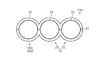
・図6に示すように、第1実施形態において、第1収容部51及び第2収容部52に加えて、第2収容部52に隣接する第3収容部353を設け、同第3収容部353を経路規制部材30を保持する第2保持部360とすればよい。これにより、バンド部61及び係止部64を省略することができる。なお図示は省略するが、この場合においても、第1実施形態と同様にして、係合孔58aを有するアーチ部58及び係合爪59aを有する第2収容凹部59を設ければよい。 In the second embodiment, a plurality ofband parts 161 may be provided. In this case, since several electric wires can be hold | maintained separately, the relative displacement of electric wires can be suppressed.
As shown in FIG. 6, in the first embodiment, in addition to thefirst storage portion 51 and the second storage portion 52, a third storage portion 353 adjacent to the second storage portion 52 is provided, and the third storage portion What is necessary is just to let 353 be the 2nd holding | maintenance part 360 holding the path | route control member 30. FIG. Thereby, the band part 61 and the latching | locking part 64 are omissible. Although illustration is omitted, in this case as well, similarly to the first embodiment, the arch portion 58 having the engagement hole 58a and the second accommodation recess 59 having the engagement claw 59a may be provided.
・図6に示すように、第1実施形態において、第1収容部51及び第2収容部52に加えて、第2収容部52に隣接する第3収容部353を設け、同第3収容部353を経路規制部材30を保持する第2保持部360とすればよい。これにより、バンド部61及び係止部64を省略することができる。なお図示は省略するが、この場合においても、第1実施形態と同様にして、係合孔58aを有するアーチ部58及び係合爪59aを有する第2収容凹部59を設ければよい。 In the second embodiment, a plurality of
As shown in FIG. 6, in the first embodiment, in addition to the
・第1実施形態において、例えば扁平な筒形状をなす収容部を有する第1保持部を採用することで、複数の電線20を一括で収容するようにしてもよい。
・第1実施形態において、第1収容部51及び第2収容部52の断面形状は円形状でなくてもよく、多角形状であってもよい。 -In 1st Embodiment, you may make it accommodate the someelectric wire 20 collectively by employ | adopting the 1st holding | maintenance part which has the accommodating part which makes a flat cylinder shape, for example.
-In 1st Embodiment, the cross-sectional shape of the1st accommodating part 51 and the 2nd accommodating part 52 may not be circular shape, and polygonal shape may be sufficient as it.
・第1実施形態において、第1収容部51及び第2収容部52の断面形状は円形状でなくてもよく、多角形状であってもよい。 -In 1st Embodiment, you may make it accommodate the some
-In 1st Embodiment, the cross-sectional shape of the
・経路規制部材30はアルミニウム合金に限定されない。他に例えば、銅合金などの他の金属材料によって経路規制部材を形成することもできる。また、樹脂材料によって経路規制部材を形成することもできる。この場合、予めワイヤハーネスの配索経路に沿った所定の形状に型成形すればよい。
· The path regulating member 30 is not limited to an aluminum alloy. In addition, for example, the path regulating member can be formed of another metal material such as a copper alloy. Moreover, a path | route control member can also be formed with a resin material. In this case, what is necessary is just to mold into a predetermined shape along the wiring path of the wire harness in advance.
・経路規制部材30の長さ方向に直交する断面の断面積は、電線20の長さ方向に直交する断面の断面積と略同一でなくてもよい。要は、経路規制部材30が電線20の経路を規制できればよく、例えば、経路規制部材30の長さ方向に直交する断面の断面積が、電線20の長さ方向に直交する断面の断面積より小さくてもよい。
The cross-sectional area of the cross section orthogonal to the length direction of the path regulating member 30 may not be substantially the same as the cross-sectional area of the cross section orthogonal to the length direction of the electric wire 20. In short, it is sufficient that the path regulating member 30 can regulate the path of the electric wire 20. For example, the cross-sectional area of the cross section orthogonal to the length direction of the path restricting member 30 is greater than the cross sectional area of the cross section orthogonal to the length direction of the electric wire 20. It may be small.
・第1保持部と電線20との間や第2保持部と経路規制部材30との間に滑り止め部材を介在させることもできる。
・クリップ40,140の取り付け姿勢は特に限定されない。要は、電線20に対する経路規制部材30の相対位置が維持できればよい。 -An anti-slip | skid member can also be interposed between the 1st holding | maintenance part and theelectric wire 20, and between a 2nd holding | maintenance part and the path | route control member 30. FIG.
-The attachment posture of the clips 40 and 140 is not particularly limited. In short, it is only necessary that the relative position of the path regulating member 30 with respect to the electric wire 20 can be maintained.
・クリップ40,140の取り付け姿勢は特に限定されない。要は、電線20に対する経路規制部材30の相対位置が維持できればよい。 -An anti-slip | skid member can also be interposed between the 1st holding | maintenance part and the
-The attachment posture of the
本発明がその技術的思想から逸脱しない範囲で他の特有の形態で具体化されてもよいということは当業者にとって明らかであろう。例えば、実施形態(あるいはその1つ又は複数の態様)において説明した部品のうちの一部を省略したり、いくつかの部品を組合せてもよい。本発明の範囲は、添付の請求の範囲を参照して、請求の範囲が権利を与えられる均等物の全範囲と共に確定されるべきである。
It will be apparent to those skilled in the art that the present invention may be embodied in other specific forms without departing from the technical concept thereof. For example, some of the parts described in the embodiment (or one or more aspects thereof) may be omitted, or some parts may be combined. The scope of the invention should be determined with reference to the appended claims, along with the full scope of equivalents to which such claims are entitled.
10,110…ワイヤハーネス、20…電線、30…経路規制部材、40,140,340…クリップ(ワイヤハーネス用クリップ)、50,160…第1保持部、51…第1収容部、52…第2収容部、53a,53b…側壁、54a,54b…側壁、55a,55b…縁部、56a,56b…縁部、57…ヒンジ部、58…アーチ部、58a…係合孔、58b…第1収容凹部、59…第2収容凹部、59a…係合爪、60,260,360…第2保持部、61,161,261…バンド部、62,162,262…第1バンド部、63,163,263…第2バンド部、63a,163a,263a…係止突起、64,164,264…係止部、64a,164a,264a…挿通孔、70…連結部、90…車両、91…モータ、92…インバータ、353…第3収容部。
DESCRIPTION OF SYMBOLS 10,110 ... Wire harness, 20 ... Electric wire, 30 ... Path control member, 40, 140, 340 ... Clip (clip for wire harness), 50, 160 ... 1st holding | maintenance part, 51 ... 1st accommodating part, 52 ... 1st 2 accommodating part, 53a, 53b ... side wall, 54a, 54b ... side wall, 55a, 55b ... edge part, 56a, 56b ... edge part, 57 ... hinge part, 58 ... arch part, 58a ... engagement hole, 58b ... first Housing recess, 59 ... second housing recess, 59a ... engaging claw, 60,260,360 ... second holding part, 61,161,261 ... band part, 62,162,262 ... first band part, 63,163 , 263 ... second band part, 63a, 163a, 263a ... locking projection, 64, 164, 264 ... locking part, 64a, 164a, 264a ... insertion hole, 70 ... connecting part, 90 ... vehicle, 91 ... motor, 92 The inverter, 353 ... third container portion.
Claims (6)
- 電線と、前記電線よりも高い剛性を有し、前記電線を沿わせて固定することで前記電線の経路を規制する経路規制部材とを備えるワイヤハーネスに適用されるワイヤハーネス用クリップであって、
前記電線を保持する第1保持部と、
前記第1保持部に連結されるとともに前記経路規制部材を保持する第2保持部と、を備えている、
ワイヤハーネス用クリップ。 A wire harness clip applied to a wire harness comprising a wire and a route restriction member that has a higher rigidity than the wire and regulates the route of the wire by fixing the wire along the wire,
A first holding part for holding the electric wire;
A second holding part connected to the first holding part and holding the path regulating member,
Clip for wire harness. - 前記第1保持部は、前記電線を収容する筒状の収容部を備えており、
前記収容部は、開閉可能な側壁を有している、
請求項1に記載のワイヤハーネス用クリップ。 The first holding part includes a cylindrical accommodating part that accommodates the electric wire,
The accommodating portion has a side wall that can be opened and closed.
The clip for wire harnesses according to claim 1. - 前記第1保持部は、複数の前記収容部を備えており、
隣り合う前記収容部の前記側壁の外周部同士が互いに連結されている、
請求項2に記載のワイヤハーネス用クリップ。 The first holding part includes a plurality of the accommodating parts,
The outer peripheral portions of the side walls of the adjacent accommodating portions are connected to each other,
The clip for wire harnesses according to claim 2. - 前記第2保持部は、前記経路規制部材の外周を締め付けるバンド部と、前記バンド部を係止するとともに前記バンド部による締め付け度合を調節可能な係止部と、を有している、
請求項2または請求項3に記載のワイヤハーネス用クリップ。 The second holding portion includes a band portion that tightens the outer periphery of the path regulating member, and a locking portion that locks the band portion and can adjust a tightening degree by the band portion.
The wire harness clip according to claim 2 or claim 3. - 前記第1保持部及び前記第2保持部の双方は、前記電線または前記経路規制部材の外周を締め付けるバンド部と、前記バンド部を係止するとともに前記バンド部による締め付け度合を調節可能な係止部と、を有している、
請求項1に記載のワイヤハーネス用クリップ。 Both the first holding part and the second holding part are a band part that tightens the outer periphery of the electric wire or the path regulating member, and a lock that locks the band part and can adjust the tightening degree by the band part. And having a part,
The clip for wire harnesses according to claim 1. - 電線と、
前記電線よりも高い剛性を有し、前記電線を沿わせて固定することで前記電線の経路を規制する経路規制部材と、
請求項1~請求項5のいずれか一項に記載のワイヤハーネス用クリップと、を備える、
ワイヤハーネス。 Electric wires,
A path regulating member that has higher rigidity than the electric wire and regulates the path of the electric wire by fixing the electric wire along the wire;
A wire harness clip according to any one of claims 1 to 5,
Wire harness.
Applications Claiming Priority (2)
| Application Number | Priority Date | Filing Date | Title |
|---|---|---|---|
| JP2018042907A JP7013954B2 (en) | 2018-03-09 | 2018-03-09 | Wire harness clips and wire harnesses |
| JP2018-042907 | 2018-03-09 |
Publications (1)
| Publication Number | Publication Date |
|---|---|
| WO2019172019A1 true WO2019172019A1 (en) | 2019-09-12 |
Family
ID=67845644
Family Applications (1)
| Application Number | Title | Priority Date | Filing Date |
|---|---|---|---|
| PCT/JP2019/007324 WO2019172019A1 (en) | 2018-03-09 | 2019-02-26 | Wire harness grip and wire harness |
Country Status (2)
| Country | Link |
|---|---|
| JP (1) | JP7013954B2 (en) |
| WO (1) | WO2019172019A1 (en) |
Cited By (1)
| Publication number | Priority date | Publication date | Assignee | Title |
|---|---|---|---|---|
| CN111600241A (en) * | 2020-05-30 | 2020-08-28 | 林浩敏 | Cable wire routing machine capable of stably routing cables |
Citations (3)
| Publication number | Priority date | Publication date | Assignee | Title |
|---|---|---|---|---|
| JPH01115089U (en) * | 1988-01-29 | 1989-08-02 | ||
| JPH01143405U (en) * | 1988-03-28 | 1989-10-02 | ||
| JP2004534187A (en) * | 2001-06-21 | 2004-11-11 | ニューフレイ リミテッド ライアビリティ カンパニー | Retaining clip for fastening at least one line to a support |
Family Cites Families (5)
| Publication number | Priority date | Publication date | Assignee | Title |
|---|---|---|---|---|
| JP5479129B2 (en) | 2010-01-27 | 2014-04-23 | 株式会社フジクラ | Wire Harness |
| JP6180227B2 (en) | 2013-08-09 | 2017-08-16 | 矢崎総業株式会社 | Wire fixing parts |
| JP6342176B2 (en) | 2014-02-14 | 2018-06-13 | 矢崎総業株式会社 | Protector, protector connection system, and wire harness |
| JP2016144288A (en) | 2015-01-30 | 2016-08-08 | 住友電装株式会社 | Option connector fixture |
| JP2017053372A (en) | 2015-09-07 | 2017-03-16 | 住友電装株式会社 | Rigging unit with binding band |
-
2018
- 2018-03-09 JP JP2018042907A patent/JP7013954B2/en active Active
-
2019
- 2019-02-26 WO PCT/JP2019/007324 patent/WO2019172019A1/en active Application Filing
Patent Citations (3)
| Publication number | Priority date | Publication date | Assignee | Title |
|---|---|---|---|---|
| JPH01115089U (en) * | 1988-01-29 | 1989-08-02 | ||
| JPH01143405U (en) * | 1988-03-28 | 1989-10-02 | ||
| JP2004534187A (en) * | 2001-06-21 | 2004-11-11 | ニューフレイ リミテッド ライアビリティ カンパニー | Retaining clip for fastening at least one line to a support |
Cited By (2)
| Publication number | Priority date | Publication date | Assignee | Title |
|---|---|---|---|---|
| CN111600241A (en) * | 2020-05-30 | 2020-08-28 | 林浩敏 | Cable wire routing machine capable of stably routing cables |
| CN111600241B (en) * | 2020-05-30 | 2021-07-23 | 泉州台商投资区沐鸿科技有限公司 | Electric wire routing machine capable of stably routing wires |
Also Published As
| Publication number | Publication date |
|---|---|
| JP7013954B2 (en) | 2022-02-01 |
| JP2019161775A (en) | 2019-09-19 |
Similar Documents
| Publication | Publication Date | Title |
|---|---|---|
| JP4440223B2 (en) | Corrugated tube fixing structure | |
| WO2014125665A1 (en) | Clamping band fixing structure | |
| JP6015624B2 (en) | Band clip mounting structure to corrugated tube | |
| JP6626070B2 (en) | Wire harness | |
| WO2019172019A1 (en) | Wire harness grip and wire harness | |
| JP3580201B2 (en) | Grommets for wire harness | |
| JP4358640B2 (en) | Conductor holder | |
| WO2019188662A1 (en) | Path regulating member for wire harness and wire harness | |
| WO2019172018A1 (en) | Wire harness | |
| WO2019181521A1 (en) | Route restriction member for wire harness, and wire harness | |
| WO2019103030A1 (en) | Wiring harness protector and harness assembly | |
| JP2017079504A (en) | Wiring harness | |
| JP6873533B2 (en) | Protector for automobile wire harness | |
| KR100580495B1 (en) | band cable for binding wire harness | |
| JP6868457B2 (en) | Grommets and wire harnesses | |
| US9825444B2 (en) | Electrical wire cover | |
| KR101872830B1 (en) | Separation jig for wire harness | |
| WO2023058471A1 (en) | Wire harness and protector | |
| JP7214526B2 (en) | Grommet inner and grommet | |
| JP2012182940A (en) | Band clip | |
| WO2022158302A1 (en) | Wire harness | |
| JP7130376B2 (en) | protector and wire harness | |
| JP7255470B2 (en) | Wiring member support structure and wiring member | |
| JP7359806B2 (en) | Protector and wire harness | |
| JP7469183B2 (en) | Bonder Cap |
Legal Events
| Date | Code | Title | Description |
|---|---|---|---|
| 121 | Ep: the epo has been informed by wipo that ep was designated in this application |
Ref document number: 19763387 Country of ref document: EP Kind code of ref document: A1 |
|
| NENP | Non-entry into the national phase |
Ref country code: DE |
|
| 122 | Ep: pct application non-entry in european phase |
Ref document number: 19763387 Country of ref document: EP Kind code of ref document: A1 |