JP5479129B2 - Wire Harness - Google Patents
Wire Harness Download PDFInfo
- Publication number
- JP5479129B2 JP5479129B2 JP2010015296A JP2010015296A JP5479129B2 JP 5479129 B2 JP5479129 B2 JP 5479129B2 JP 2010015296 A JP2010015296 A JP 2010015296A JP 2010015296 A JP2010015296 A JP 2010015296A JP 5479129 B2 JP5479129 B2 JP 5479129B2
- Authority
- JP
- Japan
- Prior art keywords
- wire harness
- bone member
- electric
- cylindrical body
- wire
- Prior art date
- Legal status (The legal status is an assumption and is not a legal conclusion. Google has not performed a legal analysis and makes no representation as to the accuracy of the status listed.)
- Expired - Fee Related
Links
Images


Landscapes
- Insulated Conductors (AREA)
- Details Of Indoor Wiring (AREA)
- Installation Of Indoor Wiring (AREA)
Description
本発明は、可撓性を備えたシールド部材及び電線を筒体に挿通させてなるワイヤーハーネスに関するものである。 The present invention relates to a wire harness formed by inserting a flexible shield member and an electric wire through a cylindrical body.
電気自動車EV、ハイブリッド自動車HEVまたは燃料電池自動車FCVなど、電動モータを走行駆動源とする車両において、バッテリとインバータ又はインバータと電動モータを接続するためにワイヤーハーネスが用いられている。特に電気自動車等に用いられるワイヤーハーネスは、床裏などの室外に配索されることがあるため、電磁波シールド性に加え、水密性や耐チッピング性(飛石防止)も要求される。 In a vehicle using an electric motor as a driving source such as an electric vehicle EV, a hybrid vehicle HEV, or a fuel cell vehicle FCV, a wire harness is used to connect the battery and the inverter or the inverter and the electric motor. In particular, a wire harness used for an electric vehicle or the like is sometimes routed outside a room such as a floor, so that watertightness and chipping resistance (prevention of flying stones) are required in addition to electromagnetic shielding properties.
この種のワイヤーハーネスとして、複数の電線を金属製パイプで一括して包囲し、この金属製パイプをワイヤーハーネスの配索経路に沿って三次元的に曲げ加工したものが知られている(特許文献1)。 As this kind of wire harness, a plurality of electric wires are collectively surrounded by a metal pipe, and the metal pipe is three-dimensionally bent along the wiring path of the wire harness (patent) Reference 1).
しかしながら、複数の電線を一括して剛性パイプで包囲するためには、電線の束よりも太い剛性パイプを用いる必要があるため、車両への組み付け作業前に、ワイヤーハーネスを配索経路に沿って三次元的に曲げ加工するにあたって、太い剛性パイプを曲げ加工可能な大規模な曲げ加工用の装置が必要となるという問題がある。 However, in order to collectively enclose a plurality of electric wires with a rigid pipe, it is necessary to use a rigid pipe that is thicker than the bundle of electric wires. Therefore, before assembling to the vehicle, connect the wire harness along the routing route. When bending three-dimensionally, there is a problem that a large-scale bending apparatus capable of bending a thick rigid pipe is required.
本発明が解決しようとする課題は、配索経路に沿って三次元的に曲げ加工がし易く、かつ、配索経路に沿った形状に保持されて車両への組み付け作業性に優れたワイヤーハーネスを提供することである。 The problem to be solved by the present invention is a wire harness that is easy to bend three-dimensionally along the routing route and that is held in a shape along the routing route and has excellent workability in assembling to a vehicle. Is to provide.
本発明では、複数の電線と、前記複数の電線を一括して包囲する可撓性を備えたシールド部材と、前記シールド部材を包囲する可撓性を備えた筒体と、前記電線が配索される経路に応じた形状に形成され、前記筒体に結束された骨部材と、を備えたことを特徴とするワイヤーハーネスを提供することにより、上記課題を解決する。 In the present invention, a plurality of electric wires, a flexible shield member that collectively surrounds the plurality of electric wires, a flexible cylinder that surrounds the shield member, and the electric wires are routed The above-mentioned problem is solved by providing a wire harness characterized by comprising a bone member that is formed in a shape according to a route to be formed and bound to the cylindrical body.
また、本発明では、複数の電線と、前記複数の電線を一括して包囲する可撓性を備えたシールド部材と、前記シールド部材を包囲する可撓性を備えた筒体と、前記電線が配索される経路に応じた形状に形成され、前記筒体に包囲された骨部材と、を備えたことを特徴とするワイヤーハーネスを提供することにより、上記課題を解決する。 In the present invention, a plurality of electric wires, a flexible shield member that collectively surrounds the plurality of electric wires, a flexible cylinder that surrounds the shield member, and the electric wires The above-mentioned problems are solved by providing a wire harness comprising a bone member formed in a shape corresponding to a route to be routed and surrounded by the cylindrical body.
上記発明において、前記骨部材は、前記筒体の径よりも細く構成することができる。 In the above invention, the bone member can be configured to be thinner than the diameter of the cylindrical body.
上記発明において、前記骨部材は、中空部を有するように構成することができる。 In the above invention, the bone member can be configured to have a hollow portion.
上記発明において、前記骨部材は、金属製の材料で構成することができる。 In the above invention, the bone member may be made of a metal material.
上記発明において、前記筒体は、着色されたコルゲート管で構成することができる。 In the above invention, the cylindrical body can be constituted by a colored corrugated tube.
上記発明において、前記電線は、自動車に搭載された機器間に接続され、前記筒体は、前記自動車の車体の床裏に配索されるように構成することができる。 In the above invention, the electric wire may be connected between devices mounted on an automobile, and the cylindrical body may be routed behind the floor of the automobile body.
本発明によれば、可撓性を備えた筒体によって複数の電線及び可撓性シールド部材を一括して包囲し、この筒体の内側又は外側に、電線の配索経路に応じた形状に形成された骨部材を配置するので、複数の電線を一括して包囲する剛性パイプを用いなくても、可撓性を備えた電線及びシールド部材を配索経路に沿った形状に保持しつつ、軽量なワイヤーハーネスを提供することができる。この結果、組み付け作業性に優れたワイヤーハーネスを提供することができる。 According to the present invention, a plurality of electric wires and a flexible shield member are collectively surrounded by a cylindrical body having flexibility, and a shape corresponding to the wiring route of the electric wires is formed inside or outside the cylindrical body. Since the formed bone member is arranged, it is possible to hold the flexible electric wire and the shield member in a shape along the routing path without using a rigid pipe that collectively surrounds a plurality of electric wires, A lightweight wire harness can be provided. As a result, the wire harness excellent in assembly workability can be provided.
また、本発明によれば、電線が配索される経路に応じた形状に形成された骨部材には、複数の電線を一括して包囲する太さが要求されないので、小規模な曲げ加工用の装置で加工することができる。この結果、配索経路に沿って三次元的に曲げ加工に要する労力及びコストを低減させることができる。 In addition, according to the present invention, the bone member formed in a shape corresponding to the route in which the electric wires are routed does not require a thickness that collectively surrounds the plurality of electric wires. It can be processed with the equipment. As a result, it is possible to reduce the labor and cost required for bending three-dimensionally along the routing path.
以下、本発明の実施形態を図面に基づいて説明する。 Hereinafter, embodiments of the present invention will be described with reference to the drawings.
図1〜図3は本発明の一実施の形態を適用した電気自動車を示す図である。図1は本発明の一実施形態のワイヤーハーネス1を適用した電気自動車2を示す底面図(床裏図)、図2は図1の電気自動車2の側面図、図3は図1の電気自動車の駆動系を示すブロック図である。
1 to 3 are diagrams showing an electric vehicle to which an embodiment of the present invention is applied. 1 is a bottom view (floor back view) showing an
本実施形態においては、電動モータを走行駆動源とする電気自動車のインバータと電動モータとを接続する電力供給ラインに本発明に係るワイヤーハーネスを適用した例について説明する。 In this embodiment, an example will be described in which the wire harness according to the present invention is applied to a power supply line that connects an electric motor and an inverter of an electric vehicle using an electric motor as a travel drive source.
ただし、本発明に係るワイヤーハーネスは電気自動車のインバータと電動モータとの間の電力供給ラインのほか、バッテリとインバータの間の電力供給ラインにも適用することができる。また、電動モータを走行駆動源とする電気自動車には、本例にて説明するもの以外に、内燃機関と電動モータの両方を走行駆動源とするハイブリッド自動車や、二次電池からなるバッテリに代えて燃料電池を電源とする燃料電池自動車が含まれる。 However, the wire harness according to the present invention can be applied not only to the power supply line between the inverter and the electric motor of the electric vehicle but also to the power supply line between the battery and the inverter. In addition to the electric vehicle using an electric motor as a travel drive source, a hybrid vehicle using both an internal combustion engine and an electric motor as a travel drive source, or a battery including a secondary battery, in addition to the one described in this example. And fuel cell vehicles powered by fuel cells.
図1および図2に示すように、本例の電気自動車2では、電動モータ24がフロントトランクルーム212(いわゆるエンジンルーム)に配置される一方で、バッテリ22(補機用バッテリ22aを含む)とインバータ23はリヤトランクルーム213に配置されている。このため、バッテリ22とインバータ23とを接続する電力供給ライン(直流)用のワイヤーハーネス28はリヤトランクルーム213内で配索されるが、インバータ23と電動モータ24とを接続する電力供給ライン(交流)用のワイヤーハーネス1はリヤトランクルーム213から車体21の床裏211を通ってフロントトランクルーム212まで配索されている。
As shown in FIGS. 1 and 2, in the
また、各種電装品のアクチュエータに電力を供給するECU(Electronic Control Unit)がフロントトランクルーム212に隣接する助手席のコンソールボックスの下に固定されており、補機用バッテリ22aがリヤトランクルーム213に配置されているので、補機用バッテリ22aとECUを接続する補機用ケーブル11Aもワイヤーハーネス1に沿って配索することができる。
In addition, an ECU (Electronic Control Unit) that supplies electric power to actuators of various electrical components is fixed under the console box of the passenger seat adjacent to the
本例の電気自動車2は、図3に示すように、リチウムイオン電池などの二次電池からなるバッテリ22と、このバッテリの直流電力を交流電力に変換するインバータ23と、走行駆動源である三相交流の電動モータ24とを備え、電動モータ24の出力軸24aに接続された変速機25およびディファレンシャルギヤ26を介して、電動モータ24の出力が駆動輪27,27に伝達される。
As shown in FIG. 3, the
なお、インバータ23は、直列に接続された2つのスイッチング素子(トランジスタTr)が3列並列に接続された回路を備え、6つのスイッチング回路を所定の駆動信号によりスイッチングさせることにより、バッテリ22からの直流電力を三相交流電力に変換する電力変換装置である。また、電動モータ24の回生時には回生された交流電力をインバータ23により直流電力に変換し、これをバッテリ22に充電することもできる。
The
また、本実施形態の電気自動車2は、図3に示すように、コンバータ23aを備えることができる。このコンバータ23aは、回生された交流電力を直流電力に変換し、12Vに降圧して補機用バッテリ22aに充電する。補機用バッテリ22aに蓄電された電力はECU(Electronic Control Unit)を介してドアの開閉やターンシグナルランプ(方向指示灯)などの電装品に供給される。
Moreover, the
これらの機器が搭載された本例の電気自動車2の車体21のアンダーボディは、図1及び図2に示すように、フロントトランクルーム212と車室内214とを仕切るダッシュパネル215と、車室内の床面を構成するフロントフロアパネル216と、リヤトランクルーム213の床面を構成するリヤフロアパネル217と、フロントフロアパネル216とリヤフロアパネル217とを繋ぐエクステンションパネル218とが溶接などにより接合されている。
As shown in FIGS. 1 and 2, the underbody of the
そして、こうした車体構造に対しインバータ23と電動モータ24とを接続する電力供給ライン(交流)用のワイヤーハーネス1が、図2に示すようにインバータ23が搭載されたリヤトランクルーム213からリヤフロアパネル217に開設された孔を介して床裏211に挿通され、ここからエクステンションパネル218の面に沿ってフロントフロアパネル216の後端に至り、さらにここからフロントフロアパネル216の床裏211の面に沿って配索されてダッシュパネル215の下端に至り、ダッシュパネル215の面に沿って立ち上がって電動モータ24まで配索されている。先述したように、補機用バッテリ22aとECUを接続する補機用ケーブル11Aも、このワイヤーハーネス1と同じ経路で配索することができる。
Then, the
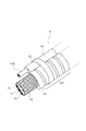
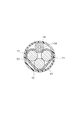
以下、図4及び図5に基づいて、本発明の実施形態に係るワイヤーハーネス1を構成する各部材について説明する。図4は図1のワイヤーハーネス1の一部を示す斜視図、図5は図1のワイヤーハーネス1のV−V線に沿う断面図である。
Hereinafter, based on FIG.4 and FIG.5, each member which comprises the
同図に示すように、本実施形態のワイヤーハーネス1は、三相交流電力(U,V,W相)用の3本の電線11と、これらの電線11を一括して包囲する可撓性のシールド部材12と、このシールド部材12を包囲する可撓性の筒体13と、この筒体13に結束部材15で結束された骨部材14とを備えている。
As shown in the figure, the
電線11を包囲するシールド部材12は、アルミニウム、ステンレス鋼、銅、アルミニウム合金または銅合金などの電磁波シールド性を有する金属で構成されている。本実施形態のシールド部材12は、導電性金属細線が網状に編み込まれた編組部材から構成されている。このように、編組部材からなるシールド部材12は可撓性を備えており、任意の方向に屈曲が可能である。また、シールド部材12は、金属製のチューブで構成することも可能であるし、電線11に巻き付けられた金属箔テープで構成することも可能である。
The
本実施形態の筒体13は、ナイロン、ポリエステル、ポリプロピレンなどの樹脂で構成されている。特に限定されないが、筒体13は耐熱性及び耐傷性を備える樹脂材料で構成されることが望ましい。また、本実施形態の筒体13は、全体が軸方向に沿って径が交互に増減する波形の、いわゆる蛇腹状に形成されている。この波形に形成された部分を蛇腹部131と称する。本例の蛇腹部131を構成する波形の形状(コルゲート形状)は特に限定されず、螺旋状の山および谷の組み合わせ、単一の山および谷の組み合わせのほか、いわゆるインターロックチューブ構造も含まれる。このような可撓性の蛇腹部131を有する筒体13で電線11及びシールド部材12を包むことにより、水密性、耐チッピング性を確保するとともに、搬送時には所望の形状に変形させて荷姿容積を小さくすることができる。
The
本実施形態の筒体13は、着色材料を含む樹脂を用いて成形された、蛇腹部131を備える有色のコルゲート管13である。特に限定されないが、コルゲート管13の色を黄色、橙色、赤色にすることにより、内部が高電圧であることを示すことができる。ちなみに、高電圧な部分に橙色を付することは日本国の法規に基づく要請であるが、金属製のシールド部材に着色する場合は、油分除去、下塗り(防錆処理、密着性向上処理)、上塗りなどを含む金属塗装工程が必要となり製造コストがかかるという問題がある。これに対し、本実施形態では、着色材料を含む樹脂を用いて筒体13を成形できるので、金属塗装をする場合よりも製造コストを低減させることができる。
The
本実施形態の骨部材14は、電線11が配索される経路に応じた形状に予め形成された金属製又は樹脂製の剛性棒状体である。骨部材14は、筒体13の延在方向に沿ってその外周面側に配置されており、結束部材15によって筒体13に結束されている。後に詳述するが、本実施形態の骨部材14は、電線11が配索される経路のほぼ全体(機器に接続される両端を除く部分)に沿って形成されている。この骨部材14は剛性を備えているため、可撓性を備えた電線11、シールド部材12及び筒体13のほぼ全体(機器に接続される両端を除く部分)を所定の形状に保つことができる。もっとも、骨部材14を経路の全体ではなく、経路の一部に沿うように形成することも可能である。
The
図5に示すように、本実施形態の骨部材14は、その直径が筒体13の径よりも細く構成されている。特に限定されないが、骨部材14は、複数の電線11を覆うシールド部材12の外接円の直径、又は複数の電線の束の外接円の直径よりも細くすることができる。このように、電線11の束を一括して包囲する場合よりも骨部材14を細く構成することができるので、ワイヤーハーネス1を軽量にすることができる。その結果、ワイヤーハーネス1を自動車2の車体21の裏側に配索する際の組み付け作業性を向上させることができる。
As shown in FIG. 5, the
このように、骨部材14を筒体13よりも細く構成することにより、骨部材14を所定の形状に形成する際に、大規模な折り曲げ装置を必要とせず、小規模な曲げ加工用の装置で加工することができる。この結果、配索経路に沿って三次元的に曲げ加工がし易く、製造コストの低減が可能なワイヤーハーネスを提供することができる。
Thus, by forming the
また、図4及び図5に示すように、本実施形態の骨部材14は、中空部を有する管構造にすることができる。このように、骨部材14を管構造にすることにより、同図のように、補機用バッテリ22aとECUを接続する補機用ケーブル11Aを骨部材14の中空部に挿通させることができる。このように、骨部材14に補機用ケーブル11Aを挿通させることにより、車体21の床裏211に配索される補機用ケーブル11Aを外傷から守り、耐チッピング性能を向上させることができる。
Moreover, as shown in FIG.4 and FIG.5, the
さらに、本実施形態の骨部材14は、アルミニウム、ステンレス鋼、銅、アルミニウム合金または銅合金などの金属から構成することができる。このように、電磁波シールド性能のある金属から骨部材14を構成することにより、本例に示すように、骨部材14に補機用ケーブル11Aを挿通させた場合に、補機用ケーブル11Aをシールドすることができる。特に高電圧の電線11と隣接して配索すると電線11からのノイズが低電圧の補機用ケーブル11Aに乗り易いが、電磁波シールド性能のある骨部材14を挿通させることでノイズの発生を抑制することができる。
Furthermore, the
なお、骨部材14の形状を中空部の無い中実な円柱形状とすることもできる。この場合は、補機用ケーブル11Aを筒体13に挿通し、補機用ケーブル11Aを筒体13に包囲させて保護することができる。
In addition, the shape of the
また、骨部材14の材料を、金属ではなく、ポリアミド系樹脂、塩化ビニリデン樹脂、エポキシ樹脂、フッ素樹脂などの耐熱性のある樹脂材料から骨部材14を構成することもできる。この場合も、骨部材14の形状を中空部の無い中実な円柱形状として、補機用ケーブル11Aを筒体13に挿通させることができる。もちろん、樹脂製の骨部材14を管構造として、補機用ケーブル11Aを骨部材14の中空部に挿通させることもできる。骨部材14を樹脂製とすることにより、金属製とした場合よりもワイヤーハーネス1を軽量にすることができる。
Alternatively, the
本実施形態の骨部材14は、同図に示すように、筒体13の外周面に、その延在方向に沿って配置されており、結束部材15によって筒体13に結束されている。特に限定されないが、結束部材14としては、樹脂製のインシュロックや、熱収縮性の樹脂バンドや、接着面を有するテープや、金属製の締結具などを用いることができる。
The
骨部材14と一体に結束することにより、可撓性を有する電線11,補機用ケーブル11A、シールド部材12及び筒体13を、電線11,11Aの配索経路に沿う三次元形状に保つことができるので、組み付け作業における取り扱いを容易にすることができる。
By tying together with the
また、図6に示すように、骨部材14を筒体13に挿通し、骨部材を筒体13によって包囲させるようにすることもできる。この場合は、筒体13の端部から骨部材14を挿入してもよいが、筒体13の延在方向に沿って形成された切れ目から骨部材14を入れ込むようにすることもできる。筒体13の延在方向に沿って切れ目が形成されている場合は、骨部材14を入れ込んでから接着面を備えるテープを筒体13の周囲に巻きつけて骨部材と筒体13等を一体に結束させることが望ましい。
In addition, as shown in FIG. 6, the
本例では、骨部材14を、中空部を有する管構造とし、その中空部に補機用ケーブル11Aを挿通させているが、骨部材14を中実な円柱状とし、補機用ケーブル11Aを筒体13の内側又は外側に配置することができる。骨部材14を管構造とした場合であっても、補機用ケーブル11Aを骨部材14の中空部に挿通させずに、筒体13の内側又は外側に配置することも可能である。
In this example, the
次に、ワイヤーハーネス1の組み立て及び取り付け手法について説明する。
Next, the assembly and attachment method of the
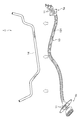
まず、骨部材14を準備する。図7に示すように、骨部材14は、電線11が配索される経路のほぼ全体(機器に接続される両端を除く部分)に沿って形成されている。
First, the
また、同図に示す筒体13には、電線11及び電線11を包囲しているシールド部材12が挿通されている。なお、電線11の一端には電動モータ24の入出力端子に接続されるコネクタ1aが取り付けられ、他端にはインバータ23の入出力端子に接続されるコネクタ1bが取り付けられている。
Further, an
ちなみに、本実施形態では、骨部材14と電線11及びシールド部材12を包囲する筒体13を別々に準備して、電気自動車の組立工場までトラックなどにより搬送することができる。本実施形態においては、シールド部材12が編組で構成され、筒体13が蛇腹部131を有するチューブ構造とされているので、電線11及びシールド部材12が挿通された筒体13は三次元的可撓性を備えている。このため、搬送時には所望の形状に変形できるため、その荷姿容積を小さくすることができる。この結果、搬送に係るコストを低減させることができる。
Incidentally, in this embodiment, the
ところで、上述したように、搬送時においてはワイヤーハーネス1が可撓性を備えることは好ましいことであるが、電気自動車2のリヤトランクルーム213からフロントトランクルーム212まで配索するとなると、ワイヤーハーネス1は3〜4m前後の長尺物になるので、車体21に組み付ける際にワイヤーハーネス1の形状が不安定になり作業性が低下するおそれがある。
By the way, as described above, it is preferable that the
本例では、搬送を終了して電気自動車2に組み付ける前に、ワイヤーハーネス1を電線11,11Aの配索経路に沿う三次元形状に形成された骨部材14に結束部材15を用いて結束し、結束後に車体21に組み付ける。
In this example, before the transportation is finished and assembled to the
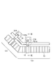
図8及び図9は、結束され車体21に組み付けられたワイヤーハーネス1を示す図である。図8は、図1のZ部を拡大して示す平面図、図9は図8のIX−IX線に沿う断面図である。
8 and 9 are diagrams showing the
本例の結束部材15は剛性を備える金属や樹脂などで構成され、筒体13と骨部材14を結束する。同図に示す結束部材15は、筒体13と骨部材14を両側面から挟み込んで保持する一対の保持部を備えており、筒体13と骨部材14を挟み込んだ状態の一対の保持部をボルト151aで締結することにより、筒体13と骨部材14を結束することができる。
The bundling
このように、骨部材14と結束されることによって、電線11、シールド部材12及び筒体13は、配索経路に沿った形状を保つことができる。
Thus, the
ワイヤーハーネス1の全体の形状が配索経路に沿って保持されたら、ワイヤーハーネス1を車体21の床裏211に接近させ、図8および図9に示すようにフロントフロアパネル216に予め溶接されたワイヤーハーネス1の固定用ブラケット219に、結束部材15をボルト151bで固定する。これにより、ワイヤーハーネス1が車体21の床裏211に固定されることになる。
When the overall shape of the
本例では、骨部材14と筒体13とを結束させる結束部材15を用いて、ワイヤーハーネス1を車体21に固定するので専用の固定部品を省略することができるというメリットもある。
In this example, since the
なお、図6に示すように骨部材14を筒体13に挿通させる場合には、図8及び図9に示す結束部材15を、車体21にワイヤーハーネス1を固定する固定部品として用いることができる。
When the
以上のように、本発明に係る本実施形態によれば、複数の電線を一括して包囲する剛性パイプを用いなくても、骨部材14により、電線11、シールド部材12及び筒体13を配索経路に沿った形状に保持できるので、軽量なワイヤーハーネスを提供することができる。この結果、組み付け作業性に優れたワイヤーハーネスを提供することができる。
As described above, according to this embodiment of the present invention, the
しかも、本実施形態では、骨部材14が電線11の配索される経路の全体に配置されているので、組み付け作業時に可撓性のある電線11、シールド部材12及び筒体13の形状が保持されるため、組み付け作業性に優れたワイヤーハーネスを提供することができる。
In addition, in the present embodiment, since the
また、本発明によれば、電線が配索される経路に応じた形状に形成された骨部材14には、複数の電線を一括して包囲する太さが要求されないので、小規模な曲げ加工用の装置で加工することができる。この結果、配索経路に沿って三次元的に曲げ加工にかかる労力及びコストを低減させることができる。
In addition, according to the present invention, the
以上説明した実施形態は、本発明の理解を容易にするために記載されたものであって、本発明を限定するために記載されたものではない。したがって、上記の実施形態に開示された各要素は、本発明の技術的範囲に属する全ての設計変更や均等物をも含む趣旨である。 The embodiment described above is described for facilitating understanding of the present invention, and is not described for limiting the present invention. Therefore, each element disclosed in the above embodiment is intended to include all design changes and equivalents belonging to the technical scope of the present invention.
たとえば、図1および図2に示すバッテリ22、インバータ23および電動モータ24のレイアウトに代えて、バッテリ22をリヤトランクルームに配置し、インバータ23をフロントトランクルームに配置することもできる。この場合は、バッテリ22とインバータ23を接続する電力供給ライン(直流)用のワイヤーハーネス28に本発明に係るワイヤーハーネスを適用することが好ましい。
For example, instead of the layout of the
1…ワイヤーハーネス
1a,1b…コネクタ
11…電線
11A…補機用ケーブル
12…シールド部材
13…筒体
131…蛇腹部
14…骨部材
15…結束部材
151a,151b…ボルト
2…電気自動車
21…車体
211…床裏
212…フロントトランクルーム
213…リヤトランクルーム
214…車室内
215…ダッシュパネル
216…フロントフロアパネル
217…リヤフロアパネル
218…エクステンションパネル
219…固定用ブラケット
22…バッテリ
23…インバータ
24…電動モータ
25…変速機
26…ディファレンシャルギヤ
27…駆動輪
28…電力供給ライン(直流)用のワイヤーハーネス
DESCRIPTION OF
Claims (7)
前記複数の電線を一括して包囲する可撓性を備えたシールド部材と、
前記シールド部材を包囲する可撓性を備えた筒体と、
前記電線が配索される経路に応じた形状に形成され、前記筒体に結束された骨部材と、を備えたことを特徴とするワイヤーハーネス。 Multiple wires,
A flexible shielding member that collectively surrounds the plurality of electric wires;
A flexible cylinder surrounding the shield member;
A wire harness comprising: a bone member formed in a shape corresponding to a route through which the electric wire is routed and bound to the cylindrical body.
前記複数の電線を一括して包囲する可撓性を備えたシールド部材と、
前記シールド部材を包囲する可撓性を備えた筒体と、
前記電線が配索される経路に応じた形状に形成され、前記筒体に包囲された骨部材と、を備えたことを特徴とするワイヤーハーネス。 Multiple wires,
A flexible shielding member that collectively surrounds the plurality of electric wires;
A flexible cylinder surrounding the shield member;
A wire harness comprising: a bone member formed in a shape corresponding to a route through which the electric wire is routed and surrounded by the cylindrical body.
前記骨部材は、前記筒体の径よりも細いことを特徴とするワイヤーハーネス。 In the wire harness according to claim 1 or 2,
The wire harness is characterized in that the bone member is thinner than the diameter of the cylindrical body.
前記骨部材は、中空部を有することを特徴とするワイヤーハーネス。 In the wire harness as described in any one of Claims 1-3,
The said bone member has a hollow part, The wire harness characterized by the above-mentioned.
前記骨部材は、金属製であることを特徴とするワイヤーハーネス。 The wire harness according to claim 4,
The wire harness is characterized in that the bone member is made of metal.
前記筒体は、着色されたコルゲート管であることを特徴とするワイヤーハーネス。 In the wire harness as described in any one of Claims 1-5,
The said wire is a colored corrugated pipe | tube, The wire harness characterized by the above-mentioned.
前記電線は、自動車に搭載された機器間に接続され、
前記筒体は、前記自動車の車体の床裏に配索されるワイヤーハーネス。 In the wire harness as described in any one of Claims 1-6,
The electric wire is connected between devices mounted on an automobile,
The said cylinder is a wire harness routed in the floor under the body of the said motor vehicle.
Priority Applications (1)
| Application Number | Priority Date | Filing Date | Title |
|---|---|---|---|
| JP2010015296A JP5479129B2 (en) | 2010-01-27 | 2010-01-27 | Wire Harness |
Applications Claiming Priority (1)
| Application Number | Priority Date | Filing Date | Title |
|---|---|---|---|
| JP2010015296A JP5479129B2 (en) | 2010-01-27 | 2010-01-27 | Wire Harness |
Publications (2)
| Publication Number | Publication Date |
|---|---|
| JP2011155763A JP2011155763A (en) | 2011-08-11 |
| JP5479129B2 true JP5479129B2 (en) | 2014-04-23 |
Family
ID=44541297
Family Applications (1)
| Application Number | Title | Priority Date | Filing Date |
|---|---|---|---|
| JP2010015296A Expired - Fee Related JP5479129B2 (en) | 2010-01-27 | 2010-01-27 | Wire Harness |
Country Status (1)
| Country | Link |
|---|---|
| JP (1) | JP5479129B2 (en) |
Cited By (1)
| Publication number | Priority date | Publication date | Assignee | Title |
|---|---|---|---|---|
| CN111344922A (en) * | 2017-11-30 | 2020-06-26 | 住友电装株式会社 | Wire harness |
Families Citing this family (18)
| Publication number | Priority date | Publication date | Assignee | Title |
|---|---|---|---|---|
| JP5434748B2 (en) * | 2009-12-24 | 2014-03-05 | 日立金属株式会社 | Conductive path for vehicles |
| JP5440446B2 (en) * | 2010-08-26 | 2014-03-12 | 日立金属株式会社 | Conductive path for vehicles |
| JP5712013B2 (en) * | 2011-03-22 | 2015-05-07 | 矢崎総業株式会社 | Wiring harness wiring structure |
| US8963366B2 (en) * | 2011-10-04 | 2015-02-24 | Hitachi, Ltd. | System for power transmission |
| JP2013180727A (en) * | 2012-03-05 | 2013-09-12 | Nissan Motor Co Ltd | Harness distribution structure of electric vehicle |
| JP5835019B2 (en) | 2012-03-05 | 2015-12-24 | 日産自動車株式会社 | Electric vehicle harness arrangement structure |
| JP2013180728A (en) * | 2012-03-05 | 2013-09-12 | Nissan Motor Co Ltd | Harness wiring structure of electric vehicle |
| JP6187876B2 (en) * | 2014-12-03 | 2017-08-30 | 株式会社オートネットワーク技術研究所 | Shield conductive path |
| JP6556513B2 (en) * | 2015-06-18 | 2019-08-07 | 矢崎総業株式会社 | Connection structure and wire harness |
| JP6569603B2 (en) * | 2016-06-09 | 2019-09-04 | 株式会社オートネットワーク技術研究所 | Wire Harness |
| JP6744580B2 (en) | 2017-03-30 | 2020-08-19 | 株式会社オートネットワーク技術研究所 | Clamp and wire harness |
| JP6744585B2 (en) | 2017-03-30 | 2020-08-19 | 株式会社オートネットワーク技術研究所 | Protective member and wire harness |
| DE102017209998A1 (en) * | 2017-06-14 | 2018-12-20 | Bombardier Transportation Gmbh | Arrangement of cable bundles, vehicle and method for the production of the arrangement |
| JP7013954B2 (en) * | 2018-03-09 | 2022-02-01 | 住友電装株式会社 | Wire harness clips and wire harnesses |
| JP7409124B2 (en) * | 2020-02-04 | 2024-01-09 | 住友電装株式会社 | wire harness |
| JP7421751B2 (en) | 2020-03-30 | 2024-01-25 | 住友電装株式会社 | wire harness |
| US20230382321A1 (en) * | 2020-10-22 | 2023-11-30 | Sumitomo Wiring Systems, Ltd. | Composite wire harness |
| GB2604138A (en) * | 2021-02-25 | 2022-08-31 | Airbus Operations Ltd | Aircraft wing with fuel tank and fuel cell |
Family Cites Families (7)
| Publication number | Priority date | Publication date | Assignee | Title |
|---|---|---|---|---|
| JPH07264747A (en) * | 1994-03-16 | 1995-10-13 | Safety Denki:Kk | Flexible conduit tube |
| JP2004172476A (en) * | 2002-11-21 | 2004-06-17 | Auto Network Gijutsu Kenkyusho:Kk | Conductive path with shield function |
| JP2005323480A (en) * | 2004-05-11 | 2005-11-17 | Yazaki Corp | Pipe cable and pipe cable connection jig |
| JP4407518B2 (en) * | 2005-01-05 | 2010-02-03 | 住友電装株式会社 | Wiring structure for automobile |
| JP2007209120A (en) * | 2006-02-02 | 2007-08-16 | Yazaki Corp | Power supply harness wiring structure |
| JP2009123635A (en) * | 2007-11-19 | 2009-06-04 | Nissan Diesel Motor Co Ltd | Harness assembly |
| JP5434748B2 (en) * | 2009-12-24 | 2014-03-05 | 日立金属株式会社 | Conductive path for vehicles |
-
2010
- 2010-01-27 JP JP2010015296A patent/JP5479129B2/en not_active Expired - Fee Related
Cited By (2)
| Publication number | Priority date | Publication date | Assignee | Title |
|---|---|---|---|---|
| CN111344922A (en) * | 2017-11-30 | 2020-06-26 | 住友电装株式会社 | Wire harness |
| CN111344922B (en) * | 2017-11-30 | 2021-08-24 | 住友电装株式会社 | wiring harness |
Also Published As
| Publication number | Publication date |
|---|---|
| JP2011155763A (en) | 2011-08-11 |
Similar Documents
| Publication | Publication Date | Title |
|---|---|---|
| JP5479129B2 (en) | Wire Harness | |
| US7497284B2 (en) | Power cable holding structure for vehicle and method of assembling power cable assembly for vehicle | |
| US9524811B2 (en) | Wire harness | |
| US20160217886A1 (en) | Wiring harness having protection member | |
| JP2011028892A (en) | Wire harness | |
| JP7136542B2 (en) | wire harness | |
| JP6014910B2 (en) | High voltage conductive path and wire harness | |
| JP5175897B2 (en) | Electrical cable and electrical connector | |
| JP2012022777A (en) | Wiring harness, conveyance method of wiring harness and apparatus, and connection method between apparatus by wiring harness | |
| CN104737399B (en) | Wire harness exterior part, wire harness and method for forming wire harness exterior part | |
| JP2012059395A (en) | Conducting path structure and wire harness | |
| JP5817627B2 (en) | Electric vehicle | |
| JP2012142105A (en) | Wiring harness and method of manufacturing wiring harness | |
| JP5957781B2 (en) | Sliding clamp and clamped member mounting structure | |
| US9888618B2 (en) | Shielded harness and manufacturing method therefor | |
| JP2015201284A (en) | wire harness | |
| EP2738775B1 (en) | High-voltage conduction path and wiring harness | |
| JP2016032388A (en) | Wire harness | |
| JP5584652B2 (en) | Electric vehicle | |
| JP2013026015A (en) | Wire harness | |
| JP2012143029A (en) | Wire harness | |
| CN107499253A (en) | Wire harness | |
| JP4823559B2 (en) | Shield conductive path | |
| JP2009099356A (en) | Cable structure | |
| JP3754053B2 (en) | In-vehicle structure of high-voltage equipment box |
Legal Events
| Date | Code | Title | Description |
|---|---|---|---|
| A621 | Written request for application examination |
Free format text: JAPANESE INTERMEDIATE CODE: A621 Effective date: 20121206 |
|
| A977 | Report on retrieval |
Free format text: JAPANESE INTERMEDIATE CODE: A971007 Effective date: 20130930 |
|
| TRDD | Decision of grant or rejection written | ||
| A01 | Written decision to grant a patent or to grant a registration (utility model) |
Free format text: JAPANESE INTERMEDIATE CODE: A01 Effective date: 20140204 |
|
| A61 | First payment of annual fees (during grant procedure) |
Free format text: JAPANESE INTERMEDIATE CODE: A61 Effective date: 20140212 |
|
| R151 | Written notification of patent or utility model registration |
Ref document number: 5479129 Country of ref document: JP Free format text: JAPANESE INTERMEDIATE CODE: R151 |
|
| R250 | Receipt of annual fees |
Free format text: JAPANESE INTERMEDIATE CODE: R250 |
|
| R250 | Receipt of annual fees |
Free format text: JAPANESE INTERMEDIATE CODE: R250 |
|
| R250 | Receipt of annual fees |
Free format text: JAPANESE INTERMEDIATE CODE: R250 |
|
| R250 | Receipt of annual fees |
Free format text: JAPANESE INTERMEDIATE CODE: R250 |
|
| R250 | Receipt of annual fees |
Free format text: JAPANESE INTERMEDIATE CODE: R250 |
|
| LAPS | Cancellation because of no payment of annual fees |