WO2019171560A1 - Procédé d'affichage et dispositif d'affichage pour code bidimensionnel - Google Patents
Procédé d'affichage et dispositif d'affichage pour code bidimensionnel Download PDFInfo
- Publication number
- WO2019171560A1 WO2019171560A1 PCT/JP2018/009109 JP2018009109W WO2019171560A1 WO 2019171560 A1 WO2019171560 A1 WO 2019171560A1 JP 2018009109 W JP2018009109 W JP 2018009109W WO 2019171560 A1 WO2019171560 A1 WO 2019171560A1
- Authority
- WO
- WIPO (PCT)
- Prior art keywords
- display
- dimensional code
- defect
- light emitting
- emitting element
- Prior art date
Links
Images


Classifications
-
- G—PHYSICS
- G09—EDUCATION; CRYPTOGRAPHY; DISPLAY; ADVERTISING; SEALS
- G09F—DISPLAYING; ADVERTISING; SIGNS; LABELS OR NAME-PLATES; SEALS
- G09F9/00—Indicating arrangements for variable information in which the information is built-up on a support by selection or combination of individual elements
- G09F9/30—Indicating arrangements for variable information in which the information is built-up on a support by selection or combination of individual elements in which the desired character or characters are formed by combining individual elements
- G09F9/33—Indicating arrangements for variable information in which the information is built-up on a support by selection or combination of individual elements in which the desired character or characters are formed by combining individual elements being semiconductor devices, e.g. diodes
-
- G—PHYSICS
- G06—COMPUTING; CALCULATING OR COUNTING
- G06K—GRAPHICAL DATA READING; PRESENTATION OF DATA; RECORD CARRIERS; HANDLING RECORD CARRIERS
- G06K19/00—Record carriers for use with machines and with at least a part designed to carry digital markings
- G06K19/06—Record carriers for use with machines and with at least a part designed to carry digital markings characterised by the kind of the digital marking, e.g. shape, nature, code
- G06K19/06009—Record carriers for use with machines and with at least a part designed to carry digital markings characterised by the kind of the digital marking, e.g. shape, nature, code with optically detectable marking
- G06K19/06046—Constructional details
- G06K19/06075—Constructional details the marking containing means for error correction
-
- G—PHYSICS
- G06—COMPUTING; CALCULATING OR COUNTING
- G06K—GRAPHICAL DATA READING; PRESENTATION OF DATA; RECORD CARRIERS; HANDLING RECORD CARRIERS
- G06K19/00—Record carriers for use with machines and with at least a part designed to carry digital markings
- G06K19/06—Record carriers for use with machines and with at least a part designed to carry digital markings characterised by the kind of the digital marking, e.g. shape, nature, code
- G06K19/06009—Record carriers for use with machines and with at least a part designed to carry digital markings characterised by the kind of the digital marking, e.g. shape, nature, code with optically detectable marking
- G06K19/06037—Record carriers for use with machines and with at least a part designed to carry digital markings characterised by the kind of the digital marking, e.g. shape, nature, code with optically detectable marking multi-dimensional coding
-
- G—PHYSICS
- G06—COMPUTING; CALCULATING OR COUNTING
- G06K—GRAPHICAL DATA READING; PRESENTATION OF DATA; RECORD CARRIERS; HANDLING RECORD CARRIERS
- G06K19/00—Record carriers for use with machines and with at least a part designed to carry digital markings
- G06K19/06—Record carriers for use with machines and with at least a part designed to carry digital markings characterised by the kind of the digital marking, e.g. shape, nature, code
- G06K19/06009—Record carriers for use with machines and with at least a part designed to carry digital markings characterised by the kind of the digital marking, e.g. shape, nature, code with optically detectable marking
- G06K19/06046—Constructional details
- G06K19/06112—Constructional details the marking being simulated using a light source, e.g. a barcode shown on a display or a laser beam with time-varying intensity profile
-
- G—PHYSICS
- G09—EDUCATION; CRYPTOGRAPHY; DISPLAY; ADVERTISING; SEALS
- G09F—DISPLAYING; ADVERTISING; SIGNS; LABELS OR NAME-PLATES; SEALS
- G09F11/00—Indicating arrangements for variable information in which the complete information is permanently attached to a movable support which brings it to the display position
-
- G—PHYSICS
- G09—EDUCATION; CRYPTOGRAPHY; DISPLAY; ADVERTISING; SEALS
- G09F—DISPLAYING; ADVERTISING; SIGNS; LABELS OR NAME-PLATES; SEALS
- G09F9/00—Indicating arrangements for variable information in which the information is built-up on a support by selection or combination of individual elements
- G09F9/30—Indicating arrangements for variable information in which the information is built-up on a support by selection or combination of individual elements in which the desired character or characters are formed by combining individual elements
Definitions
- the present invention relates to a display method and a display device for displaying a two-dimensional code on a light emitting element matrix in which a thin layer made of a natural material or the like is incorporated on the outer peripheral surface of a casing.
- two-dimensional codes such as QR codes are often used (see, for example, Patent Document 1).
- a two-dimensional code is printed on a paper medium such as a newspaper or magazine in order to be guided to an Internet site that introduces the product, and is read by a portable terminal owned by the user.
- a display medium for the two-dimensional code not only a print medium such as paper but also a display such as a personal computer can be used.
- the two-dimensional code displayed on the display is a camera provided on a mobile phone or the like. Many methods such as reading are used.
- the two-dimensional code is used in various fields and variously, there is a case where display on a paper medium or a liquid crystal display is not suitable depending on the usage scene.
- a two-dimensional code is displayed beside an exhibit, the visitor can be easily guided to a Web site on which more detailed information on the exhibit is placed.
- visitors can not only appreciate the work but also touch the information about the author and the story behind the work, and enjoy the work even more. Therefore, it is conceivable to print a two-dimensional code on a paper medium and paste it on the side of each work.
- this method in order to update the display contents, there is a problem that the paper medium has to be pasted again, which is complicated.
- a liquid crystal display or the like is installed near the work and a two-dimensional code is displayed on the display, the display contents can be easily updated.
- a liquid crystal display has an inorganic form, so it cannot always be adapted to the atmosphere of the exhibition place.
- the surface of the display device is made of a natural material such as wood, it will be easy to become familiar with the atmosphere of the place and not to hinder the appreciation of artworks. .
- a natural material such as wood
- an object of the present invention is to provide a display method and a display device capable of improving the display performance of a two-dimensional code in a display panel that can be used without impairing the texture of the space.
- the two-dimensional code display method of the present invention is a natural wood, natural fiber, natural leather, or natural stone, or a synthetic material that is generated by imitating natural appearance and touch.
- the two-dimensional code is a code having information in the horizontal direction and the vertical direction.
- a QR code registered trademark
- NFC near field communication
- display failure is unclear display due to variations in materials constituting the thin layer, and correction is performed by the following steps. 1) a step (display step) of displaying a two-dimensional code on the display unit of the display panel; 2) a step of detecting unclear display (detection step); 3) A step of adjusting the display by moving or rotating the two-dimensional code (adjustment step).
- the material variation is the wood grain, fiber thickness, leather thickness, and the like.
- a two-dimensional code has an error correction capability.
- an error correction capability in the case of a QR code is about 7 to 30%.
- the step of detecting unclear display is performed when there is a display error that exceeds the range of the error correction capability.
- a method of displaying the two-dimensional code for example, a method of touching the display unit, a method of data transmission from the outside, a method of operating a switch provided on the operation display panel built-in article, or an external And a method using an infrared sensor or the like.
- the success or failure of reading is judged by the user himself.
- a method of operating a switch provided on the operation display panel built-in article is used.
- the adjustment step is performed when the error correction capability is exceeded and the reading is not completed, and the display is performed by moving or rotating the display position of the two-dimensional code.
- the movement and rotation can be performed not only once but a plurality of times, and the movement and rotation are not limited to either one, and both may be used together.
- the reason why the rotation is performed for correction is that, for example, in the case of a QR code, three cutout symbols are provided so that the QR code can be read even if it is rotated and displayed. .
- the success or failure of reading in the adjustment step for example, when the user himself / herself makes a reading error as in the detection step, there is a method of operating a switch provided on the operation display panel built-in article. Used.
- the light may be automatically turned off after a certain period of time.
- a method of operating a switch provided in the display device, an external infrared sensor, or the like may be used as a trigger in addition to a method of automatically turning off the light with time.
- the display failure is a failure of a light emitting element provided in the display panel, and correction is performed by the following steps.
- a bulb of an LED light source used for a display panel is cut.
- monitoring may be constantly performed in a state where the display panel is activated, but a method of starting monitoring by using a user operation or detection by the sensor as a trigger may be used. Since the display error becomes a problem when the error correction capability of the two-dimensional code is exceeded, the detection step detects a defective light emitting element only when it is determined that the error correction capability has been exceeded after receiving a display request. Detected. Detection of a defect of the light emitting element in the detection step and adjustment of display by moving or rotating the two-dimensional code are performed inside the apparatus provided with the display panel, not by a user operation or the like.
- the display position is adjusted so as not to exceed the error correction capability of the two-dimensional code to be displayed from the respective coordinates and the coordinates that require light emission.
- the display request may be based on a user operation, or may be performed automatically by detecting the user with an infrared sensor or the like, for example.
- the display failure is at least one of display blur due to variations in the material constituting the thin layer, or a failure of the light emitting element provided in the display panel
- the correction is performed by the following steps. a) a step of monitoring a defect of the light emitting element (monitoring step); b) receiving a display request and detecting a defect of the light emitting element (light emitting element defect detecting step); c) a first adjustment step for adjusting the display by moving or rotating the two-dimensional code; d) a step of displaying the two-dimensional code on the display unit of the display panel (display step); e) a step of detecting display blur (display blur detection step); f) A second adjustment step for adjusting the display by moving or rotating the two-dimensional code.
- the display failure can be corrected regardless of whether the display is unclear due to variations in the material constituting the thin layer or the light emitting element provided in the display panel is defective. Display performance can be improved.
- the two-dimensional code display method according to the third aspect uses both the two-dimensional code display method according to the first aspect and the two-dimensional code display method according to the second aspect.
- the two-dimensional code display method according to the first aspect may be used after the two-dimensional code display method according to the second aspect.
- the two-dimensional code display method of the present invention in order to move the two-dimensional code, 40 to 60% of the height or width of the two-dimensional code is provided on at least one of the top and bottom or the left and right of the display unit. It is preferable that a movable area is provided. Depending on the type of the two-dimensional code, it is essential that a predetermined blank area is provided. Therefore, the height or width of the two-dimensional code here is the height or width of the entire two-dimensional code including the blank area when a blank area is provided, and when the blank area is not provided. , Which means the height or width of a two-dimensional code without a blank area.
- the two-dimensional code display device of the present invention is a natural-derived wood, natural fiber, natural leather or natural stone material, or a synthetic fiber, synthetic leather or artificial stone which is a material generated by imitating natural appearance and touch
- a display failure occurs on the display panel arranged on the outer peripheral surface of the housing so that the thin layer consisting of the touches the front of the panel, the display is corrected and moved by moving or rotating the two-dimensional code.
- Means are provided.
- the two-dimensional code display device of the present invention may be provided with means for updating the two-dimensional code displayed by the display device communicating with the outside, writing by short-range wireless communication, or the like.
- display failure is unclear display due to variations in the material constituting the thin layer
- the correcting means displays the two-dimensional code on the display unit of the display panel.
- the display defect is a defect of a light emitting element provided in the display panel
- the correction means receives a display request and means for monitoring the defect of the light emitting element.
- the display failure is at least one of display blur due to variations in the material constituting the thin layer, or a failure of the light emitting element provided in the display panel
- the correcting means is means for monitoring the defect of the light emitting element, means for detecting the defect of the light emitting element in response to the display request, and a first adjusting means for adjusting the display by moving or rotating the two-dimensional code.
- the display unit of the display panel includes means for displaying a two-dimensional code, means for detecting unclear display, and second adjustment means for adjusting display by moving or rotating the two-dimensional code.
- the two-dimensional code display device is 40 to 60% of the height or width of the two-dimensional code on at least one of the top and bottom or the left and right of the display unit in order to move the two-dimensional code. It is preferable that a movable area is provided.
- the two-dimensional code display method and display device of the present invention since a naturally-derived material or the like is used for the surface, there is an effect that it can be used without damaging the texture of the space. In addition, since display defects can be corrected, there is an effect that display performance can be improved.
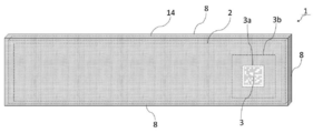
- FIG. 1 is an external view of an operation display panel built-in article on which the display device of Example 1 is mounted.
- the operation display panel built-in article 1 is covered with the protruding plate 8 in a front view, and thus has a shape as if it is a single wooden board.
- An operation display panel unit 14 is provided inside the operation display panel built-in article 1.
- the display unit 2 displays information necessary for the user (not shown) such as characters and graphics.
- a two-dimensional code display area 3a is provided in the display unit 2, and the two-dimensional code 3 is displayed in the two-dimensional code display area 3a.
- the two-dimensional code display area 3a is not fixed at the substantially right end in the display unit 2, but can be set at a free position depending on the usage form within the display unit 2. Therefore, for example, as long as the two-dimensional code 3 is displayed when the user touches any part of the display unit 2, the two-dimensional code 3 may be displayed at a part touched by the user.
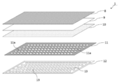
- FIG. 2 shows a configuration image diagram of an operation display panel built-in article equipped with the display device of the first embodiment.
- the operation display panel built-in article 1 includes a projecting plate 8, a transparent base material 9, a touch panel sheet 10 as a transparent conductive film, a light guide 11, and an LED array 12 as a light emitting element array. They are stacked in order.
- the projecting plate 8 is positioned on the outer surface of the operation display panel built-in article 1, and the LED array 12 is configured to be positioned inside the article.
- a Sycamore material having a high transmittance of about 10% and a good appearance is used.
- a number of LED light sources 13 are two-dimensionally arranged in the LED array 12.
- the light guide 11 guides the light emission direction of each LED light source 13 in a direction perpendicular to the substrate of the LED array 12, and is provided with the same guide holes 11 a as the number of LED light sources 13.
- the LED array 12 is composed of, for example, a total of 6400 LED light sources 13 of 32 vertically and 200 horizontally.
- One LED light source is composed of a planar mounting type LED.
- a point light source is realized by the light of one LED light source, and this is regarded as one dot, and one character or design can be expressed by 8 ⁇ 8 dots or 16 ⁇ 16 dots.
- the LED light source 13 has a size of 2 mm ⁇ 2 mm and has a size of 700 to 1000 mcd (Milli Candela), for example.
- the light guide 11 plays a role of making a character or a pattern constituted by light emitted from the LED light source 13 clearly visible through the protruding plate 8. That is, when the light guides 11 are stacked on the LED array 12, a large number of guide holes 11a are arranged in accordance with the arrangement of the LED light sources 13 so that the guide holes 11a are arranged immediately above the LED light sources 13. Is provided.
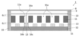
- FIG. 3 is a schematic cross-sectional view of an operation display panel built-in article on which the display device of Example 1 is mounted.
- the protruding plate 8, the transparent base material 9, the touch panel sheet 10, the light guide 11, and the LED array 12 are stacked in order from the top by the housing 15. It is glued.
- the light (16b, 16c) emitted obliquely is blocked by the light guide 11, and is projected as a straight light like the light 16a. Will reach 8.
- the housing 15 is mainly formed of ABS resin.
- the protruding plate 8 and the transparent substrate 9 or the transparent substrate 9 and the touch panel sheet 10 are bonded together without providing a gap.
- a gap G 1 is provided between the touch panel sheet 10 and the light guide 11. This is because the light guide 11 is provided with a guide hole 11a, and if the touch panel sheet 10 and the light guide 11 are bonded, the stress varies when the touch panel is operated, which may cause a malfunction. .
- a gap G 2 is also provided between the light guide 11 and the LED light source 13. Since the number of the LED light sources 13 provided in the LED array 12 and the guide holes 11a provided in the light guide 11 reaches several thousand, when the light guide 11 and the LED array 12 are stacked, an arrangement error occurs. Can occur. If the light guide 11 and the LED array 12 are bonded in a state where an error has occurred, the light emitted from the LED light source 13 does not pass through the guide hole 11a, and an accurate display is not performed. Therefore by providing the gap G 2, it is possible to prevent deterioration in display quality due to the error in arrangement of the LED light source 13 and the guide hole 11a. In addition, since the display quality is maintained even if there is some error, the manufacturing becomes easy.
- the two-dimensional code 3 shown in FIG. 1 is, for example, a QR code, and is composed of two types of cells having different colors, densities, or luminances.
- a QR code When the two-dimensional code 3 is a QR code, a blank area for four cells, three cut-out symbols, and the like are provided around the two-dimensional code. However, in the following description, these are omitted for convenience of explanation. . Also, the number of display cells differs from the actual one, and will be described in a simplified manner as shown below.
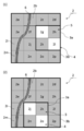
- the configuration of the display area, the movable area, and the display cell of the two-dimensional code in this embodiment will be described with reference to FIG.
- FIG. 4 is an explanatory diagram of the two-dimensional code display area and the movable area.
- the display unit 2 is provided with display cells (2a to 2p).
- the two-dimensional code display area 3a is composed of 2 ⁇ 2 in the vertical direction, and is set in the range of display cells (2f, 2g, 2j, 2k) here.
- a movable area 3b is provided with a height or width of about 50% of the two-dimensional code display area 3a in any direction, up, down, left, or right.
- a two-dimensional code display about 50% of the height H 2 of the height H 1 of the region 3a, on the two-dimensional code display region 3a, movable corresponding to display cells (2a ⁇ 2d) region 3b is provided at about 50% of the height H 3 of the height H 1 of the two-dimensional code display region 3a, under the two-dimensional code display region 3a, movable corresponding to the display cell (2m ⁇ 2p) region 3b is provided.
- each of the display cells (2a to 2p) is provided with a light emitting element, that is, an LED light source 13.
- the display cells (2a to 2p) are in the light emitting state 4 shown in white or the non-light emitting state 5 shown in gray depending on the two-dimensional code to be displayed.
- the display cell (2f, 2k) is in the light emitting state 4 and the display cell (2g, 2j) is in the non-light emitting state 5.
- the display cell (2f, 2k) in the light emitting state 4 is recognized as white
- the display cell (2g, 2j) in the non-light emitting state 5 is recognized as black.
- the configurations of the two-dimensional code display area and the movable area shown in FIG. 4 are the same in the second embodiment described later.
- FIG. 5 is a flowchart of the display method according to the first embodiment.
- the user contacts the display unit 2 (step S01), and the two-dimensional code 3 is displayed on the display unit 2 (step S02).
- a method of displaying the two-dimensional code 3 in addition to the method of contacting the display unit 2, a method of transmitting data from the outside, a method of operating a switch provided on the operation display panel built-in article 1, or an external An infrared sensor or the like may be used.
- the user reads the displayed two-dimensional code 3 using a camera-equipped mobile phone or the like (not shown) (step S03). Whether the reading is successful or not is judged by the user himself, and when a reading error occurs, a method of operating a switch provided on the operation display panel built-in article 1 is used. Even if a slight error occurs during reading, reading is possible as long as it is within the range of error correction capability. Even in such a case, when the reading is completed, the display is not changed, and the light emitting element dot matrix is turned off after a predetermined time (step S07).
- FIG. 6 shows a display image diagram of the two-dimensional code before using the display method of the first embodiment.
- the display cells (2f, 2k) are in the light emitting state 4, and the display cells (2g, 2j) are in the non-light emitting state 5.
- the grain 6 of the protruding plate 8 overlaps the display cell of the display unit 2.
- the display cell 2f It becomes difficult to read the light emission state 4 with a user terminal or the like. In such a case, the display is adjusted by movement or rotation.
- FIG. 7 and 8 are two-dimensional code display image diagrams when the display method of the first embodiment is used.
- FIG. 7A shows a state in which the two-dimensional code display area is moved rightward
- FIG. 8 shows a state rotated 90 ° to the right.
- the two-dimensional code display area 3a moves rightward from the range of the display cells (2f, 2g, 2j, 2k) to the range of the display cells (2g, 2h, 2k, 2l). doing.
- the two-dimensional code display area 3a does not overlap with the grain 6, and the state in which it is difficult to read the light emission state 4 of the display cell 2f is eliminated. Further, as shown in FIG.
- the two-dimensional code display area 3a is moved downward from the range of the display cells (2f, 2g, 2j, 2k) to the range of the display cells (2j, 2k, 2n, 2o). Has moved to.
- the two-dimensional code display area 3a does not overlap with the grain 6, and the state in which it is difficult to read the light emission state 4 of the display cell 2f is eliminated. In this way, it is possible to make a readable state even when moving rightward or downward.
- an arbitrary method can be used, such as selecting a position in advance, but it is preferable that the moving direction is displayed at any position within the movable region 3b. This is because as the number of display patterns increases, the reading accuracy improves.
- the two-dimensional code display area 3a remains in the range of the display cells (2f, 2g, 2j, 2k), but the display cell 2f Since the non-light-emitting state 5 is set, the state where it is difficult to read the light-emitting state 4 of the display cell 2f without overlapping the grain 6 is eliminated.
- the rotation of the two-dimensional code 3 may be used together with the movement of the two-dimensional code 3.
- the light emitting element dot matrix is turned off after a predetermined time has elapsed (step S07).
- a predetermined time By turning off the light after a certain period of time, it is possible to minimize the deterioration of the atmosphere of the place where the display is performed.
- the method of operating a switch provided on the operation display panel built-in article 1 or an external infrared sensor may be used as a trigger.
- FIG. 9 shows a flowchart of the display method of the second embodiment.
- the defect of the light emitting element dot matrix is monitored by measuring the amount of current (step S11). In such a state, the user contacts the display unit 2 (step S12). Even if the LED light source 13 is partially broken, reading is possible as long as it is within the range of error correction capability. If there is no ball break exceeding the error correction capability range (step S13), the displayed two-dimensional code is within the error correction capability range (step S16), so the two-dimensional code is displayed on the display unit. (Step S17), read by a portable terminal or the like (Step S18), and after a predetermined time elapses, the light emitting element dot matrix is turned off (Step S19).
- FIG. 10 shows a display image diagram of a two-dimensional code before using the display method of the second embodiment.
- the display cell (2f, 2k) is in the light emitting state 4, and the display cell (2g, 2g, 2j) needs to be in the non-light emitting state 5.
- the display cell (2f, 2k) is in the light emitting state 4, and the display cell (2g, 2g, 2j) needs to be in the non-light emitting state 5.
- FIG. 4 (2) in order to display the two-dimensional code 3 originally, in the two-dimensional code display area 3a, the display cell (2f, 2k) is in the light emitting state 4, and the display cell (2g, 2g, 2j) needs to be in the non-light emitting state 5.
- FIG. 4 (2) in order to display the two-dimensional code 3 originally, in the two-dimensional code display area 3a, the display cell (2f, 2k) is in the light emitting state 4, and the display cell (2g, 2g, 2j) needs to be in the non-light emitting
- the display cell 2 f is in a broken ball state 7 in the two-dimensional code display region 3 a. Therefore, the display cell 2 f is substantially in the same state as the non-light emitting state 5. Even in such a case, it is possible to read the two-dimensional code 3 within the range of the error correction capability of the two-dimensional code. However, if the error correction capability of the two-dimensional code is exceeded, the display cell 2f It becomes difficult to read the light emission state 4 with a user terminal or the like. In such a case, the display is adjusted by movement or rotation.
- FIG. 11 and 12 are two-dimensional code display image diagrams when the display method of the first embodiment is used.
- FIG. 11 (1) shows a state in which the two-dimensional code display area is moved rightward
- FIG. 11 (2) Indicates a state of moving leftward
- FIG. 12 shows a state rotated 90 ° to the right.
- the two-dimensional code display area 3a moves rightward from the range of the display cells (2f, 2g, 2j, 2k) to the range of the display cells (2g, 2h, 2k, 2l). doing.
- the two-dimensional code display area 3a is out of the area of the display cell 2f that is in the ball-out state 7, and the state in which the light emission state 4 is difficult to read is eliminated.
- the two-dimensional code display area 3a is moved leftward from the display cell (2f, 2g, 2j, 2k) to the display cell (2e, 2f, 2i, 2j). Has moved to.
- the display cell (2e, 2j) is in the light emitting state 4
- the display cell 2i is in the non-light emitting state 5
- the display cell 2f is in the out-of-bulb state 7, which is substantially the same as the non-light emitting state 5.
- the difficult situation has been resolved. In this way, it is possible to obtain a readable state even when moving in either the left or right direction.
- the two-dimensional code display area 3a remains in the range of the display cells (2f, 2g, 2j, 2k), but the display cell 2f Even in the out-of-sphere state 7, since it is the same as the non-light-emitting state 5, the state in which the light-emitting state 4 is difficult to read is eliminated.
- the movement and rotation of the two-dimensional code 3 can be performed a plurality of times, and may be used together.
- the two-dimensional code 3 is placed at any position and orientation within the movable region 3b. By changing and displaying, a display pattern increases and reading accuracy improves.
- step S15 By moving or rotating the display position of the two-dimensional code 3, it is possible to minimize the influence of the ball break (step S15), and when the two-dimensional code to be displayed is within the error correction capability range (step S16).
- the two-dimensional code 3 is displayed on the display unit 2 (step S17), read by a portable terminal or the like (step S18), and the light emitting element dot matrix is extinguished after a predetermined time has elapsed (step S19).
- step S16 when the two-dimensional code to be displayed exceeds the range of the error correction capability (step S16), it is displayed on the display unit 2 that the two-dimensional code cannot be displayed (step S20).
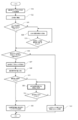
- FIG. 13 is a flowchart of the display method according to the third embodiment. As shown in FIG. 13, first, the defect of the light emitting element dot matrix is monitored by measuring the amount of current (step S21). In such a state, the user contacts the display unit 2 (step S22).
- step S23 If there is no ball break exceeding the range of error correction capability (step S23), it can be said that the two-dimensional code to be displayed is within the range of error correction capability (step S26), so the two-dimensional code is displayed on the display unit. (Step S27), read by a portable terminal or the like (Step S28).
- step S23 if there is a ball break exceeding the range of the error correction capability (step S23), the display position is adjusted by moving or rotating the display position of the two-dimensional code 3 (step S24). The movement or rotation of the display position of the two-dimensional code 3 can minimize the influence due to the ball break (step S25). If the two-dimensional code to be displayed is within the error correction capability (step S26). The two-dimensional code 3 is displayed on the display unit 2 (step S27), and is read by a portable terminal or the like (step S28). On the other hand, when the two-dimensional code to be displayed exceeds the range of the error correction capability (step S26), it is displayed on the display unit 2 that the two-dimensional code cannot be displayed (step S33). ).
- Reading is performed with a portable terminal or the like (step S28), and when the reading is completed (step S29), no further display change is performed, and the light emitting element dot matrix is turned off after a predetermined time has elapsed (step S32).
- the display position of the two-dimensional code 3 is moved or rotated to display (step S30).
- the movement / rotation here may be performed a plurality of times, or may be performed in combination with the movement / rotation. However, the movement / rotation is performed within the range of the error correction capability for the above-described ball breakage.
- step S23 The determination as to whether it is within the range of the error correction capability is made at step S23, step S26, and step S29.
- the determination in step S29 is a reading device such as a mobile phone, whereas the determination is made inside the operation display panel built-in article 1 without using a reading device such as a mobile phone.
- the user himself or herself determines whether the reading is successful or not, and the user operates a switch provided on the operation display panel built-in article 1.
- the present invention is useful as a method for displaying a two-dimensional code that is harmonized with buildings and furniture and does not impair the texture of the space. It can also be used in a payment system using a two-dimensional code.
Landscapes
- Physics & Mathematics (AREA)
- General Physics & Mathematics (AREA)
- Engineering & Computer Science (AREA)
- Theoretical Computer Science (AREA)
- Optics & Photonics (AREA)
- Control Of Indicators Other Than Cathode Ray Tubes (AREA)
- Illuminated Signs And Luminous Advertising (AREA)
Abstract
L'invention concerne un procédé d'affichage et un dispositif d'affichage avec lesquels les performances d'affichage d'un code bidimensionnel peuvent être améliorées dans un panneau d'affichage qui peut être utilisé sans endommager la texture d'un espace. Lorsqu'un défaut d'affichage se produit dans un panneau d'affichage dans lequel une couche mince, comprenant un bois d'origine naturelle, une fibre naturelle, un cuir naturel, ou une pierre naturelle, ou comprenant une fibre synthétique, un cuir synthétique, ou une pierre synthétique qui est une matière première produite en imitant un aspect naturel et un toucher naturel, est disposée sur la surface périphérique d'un boîtier de façon à être en contact avec la surface avant de panneau, un code bidimensionnel est corrigé en étant déplacé ou tourné et est affiché.
Priority Applications (5)
| Application Number | Priority Date | Filing Date | Title |
|---|---|---|---|
| JP2018526600A JP6435078B1 (ja) | 2018-03-08 | 2018-03-08 | 二次元コードの表示方法及び表示装置 |
| US16/626,155 US11275980B2 (en) | 2018-03-08 | 2018-03-08 | Display method and display device for two-dimensional code |
| CN201880042225.XA CN111788579B (zh) | 2018-03-08 | 2018-03-08 | 二维码的显示方法及显示装置 |
| PCT/JP2018/009109 WO2019171560A1 (fr) | 2018-03-08 | 2018-03-08 | Procédé d'affichage et dispositif d'affichage pour code bidimensionnel |
| EP18908741.4A EP3633554A4 (fr) | 2018-03-08 | 2018-03-08 | Procédé d'affichage et dispositif d'affichage pour code bidimensionnel |
Applications Claiming Priority (1)
| Application Number | Priority Date | Filing Date | Title |
|---|---|---|---|
| PCT/JP2018/009109 WO2019171560A1 (fr) | 2018-03-08 | 2018-03-08 | Procédé d'affichage et dispositif d'affichage pour code bidimensionnel |
Publications (1)
| Publication Number | Publication Date |
|---|---|
| WO2019171560A1 true WO2019171560A1 (fr) | 2019-09-12 |
Family
ID=64560737
Family Applications (1)
| Application Number | Title | Priority Date | Filing Date |
|---|---|---|---|
| PCT/JP2018/009109 WO2019171560A1 (fr) | 2018-03-08 | 2018-03-08 | Procédé d'affichage et dispositif d'affichage pour code bidimensionnel |
Country Status (5)
| Country | Link |
|---|---|
| US (1) | US11275980B2 (fr) |
| EP (1) | EP3633554A4 (fr) |
| JP (1) | JP6435078B1 (fr) |
| CN (1) | CN111788579B (fr) |
| WO (1) | WO2019171560A1 (fr) |
Citations (3)
| Publication number | Priority date | Publication date | Assignee | Title |
|---|---|---|---|---|
| JPH07254037A (ja) | 1994-03-14 | 1995-10-03 | Nippondenso Co Ltd | 二次元コード |
| JP2006099150A (ja) * | 2004-08-31 | 2006-04-13 | Kokolink:Kk | テレビモニタと携帯端末を用いた通信販売システム |
| JP6141567B1 (ja) * | 2016-09-06 | 2017-06-07 | 株式会社 バートン | 可視像単位識別コード構造 |
Family Cites Families (6)
| Publication number | Priority date | Publication date | Assignee | Title |
|---|---|---|---|---|
| US5295089A (en) * | 1992-05-28 | 1994-03-15 | Emilio Ambasz | Soft, foldable consumer electronic products |
| US7995178B2 (en) | 2003-12-24 | 2011-08-09 | Citizen Holdings Co., Ltd. | Liquid-crystal-display panel and barcode reading system using the same |
| WO2007127385A2 (fr) * | 2006-04-27 | 2007-11-08 | Codebroker Llc | personnalisation d'images de codes à barres pour des affichages particuliers |
| JP4900877B2 (ja) | 2007-10-18 | 2012-03-21 | 株式会社デンソー | 車両用表示装置 |
| JP2015118398A (ja) | 2013-12-16 | 2015-06-25 | 田中木材工業株式会社 | 発光機能付き筐体 |
| CN103761062B (zh) * | 2014-01-24 | 2016-06-22 | 孔阳 | 一种在二维码区域显示对应素材的方法及移动终端 |
-
2018
- 2018-03-08 EP EP18908741.4A patent/EP3633554A4/fr active Pending
- 2018-03-08 WO PCT/JP2018/009109 patent/WO2019171560A1/fr unknown
- 2018-03-08 US US16/626,155 patent/US11275980B2/en active Active
- 2018-03-08 JP JP2018526600A patent/JP6435078B1/ja active Active
- 2018-03-08 CN CN201880042225.XA patent/CN111788579B/zh active Active
Patent Citations (3)
| Publication number | Priority date | Publication date | Assignee | Title |
|---|---|---|---|---|
| JPH07254037A (ja) | 1994-03-14 | 1995-10-03 | Nippondenso Co Ltd | 二次元コード |
| JP2006099150A (ja) * | 2004-08-31 | 2006-04-13 | Kokolink:Kk | テレビモニタと携帯端末を用いた通信販売システム |
| JP6141567B1 (ja) * | 2016-09-06 | 2017-06-07 | 株式会社 バートン | 可視像単位識別コード構造 |
Non-Patent Citations (1)
| Title |
|---|
| See also references of EP3633554A4 |
Also Published As
| Publication number | Publication date |
|---|---|
| US20210295126A1 (en) | 2021-09-23 |
| EP3633554A1 (fr) | 2020-04-08 |
| CN111788579A (zh) | 2020-10-16 |
| US11275980B2 (en) | 2022-03-15 |
| JP6435078B1 (ja) | 2018-12-05 |
| CN111788579B (zh) | 2024-02-27 |
| JPWO2019171560A1 (ja) | 2020-04-16 |
| EP3633554A4 (fr) | 2020-12-30 |
Similar Documents
| Publication | Publication Date | Title |
|---|---|---|
| KR101837714B1 (ko) | 표시 장치 | |
| US7841791B2 (en) | Keyboard, lighting module for keyboard and electronic apparatus | |
| JP2008134764A (ja) | 非接触入力装置 | |
| US7214897B2 (en) | Illuminated keyboard with illuminated patterns displayed on top surface of keyboard | |
| US10210698B2 (en) | Game machine pushbutton | |
| JP2010198614A (ja) | 照明指紋センサと方法 | |
| US9437379B2 (en) | Key plate and illuminated keyboard having the same | |
| JP2008513080A (ja) | ゲームボードでポーンを検知するためのゲームボード、ポーン、シール及びシステム | |
| JP2010225480A (ja) | スイッチモジュール | |
| JP6435078B1 (ja) | 二次元コードの表示方法及び表示装置 | |
| TWI601171B (zh) | 鍵盤裝置 | |
| WO2010024137A1 (fr) | Dispositif de saisie | |
| JP2006216087A (ja) | 情報表示入力装置 | |
| JP2008053050A (ja) | 操作パネル | |
| JP2009076293A (ja) | キー入力装置 | |
| JP4582012B2 (ja) | 操作パネル装置及び表示器 | |
| WO2014017039A1 (fr) | Dispositif de lecture d'informations | |
| CN210245365U (zh) | 一种按键结构及显示装置 | |
| JP2009180832A (ja) | 操作キー表示装置及び電子機器 | |
| JP6580019B2 (ja) | 発光玩具 | |
| JP6049230B1 (ja) | 発光玩具 | |
| KR20220130554A (ko) | 화소별 출몰구조를 갖는 입체 스크린 장치 | |
| JP2016142923A (ja) | 照光表示装置 | |
| TWI390435B (zh) | 顯示裝置及光感測系統 | |
| JP2005339220A (ja) | 表示シート及びこれを用いた入力装置 |
Legal Events
| Date | Code | Title | Description |
|---|---|---|---|
| ENP | Entry into the national phase |
Ref document number: 2018526600 Country of ref document: JP Kind code of ref document: A |
|
| 121 | Ep: the epo has been informed by wipo that ep was designated in this application |
Ref document number: 18908741 Country of ref document: EP Kind code of ref document: A1 |
|
| ENP | Entry into the national phase |
Ref document number: 2018908741 Country of ref document: EP Effective date: 20200103 |
|
| NENP | Non-entry into the national phase |
Ref country code: DE |