WO2019171560A1 - Display method and display device for two-dimensional code - Google Patents
Display method and display device for two-dimensional code Download PDFInfo
- Publication number
- WO2019171560A1 WO2019171560A1 PCT/JP2018/009109 JP2018009109W WO2019171560A1 WO 2019171560 A1 WO2019171560 A1 WO 2019171560A1 JP 2018009109 W JP2018009109 W JP 2018009109W WO 2019171560 A1 WO2019171560 A1 WO 2019171560A1
- Authority
- WO
- WIPO (PCT)
- Prior art keywords
- display
- dimensional code
- defect
- light emitting
- emitting element
- Prior art date
Links
Images


Classifications
-
- G—PHYSICS
- G09—EDUCATION; CRYPTOGRAPHY; DISPLAY; ADVERTISING; SEALS
- G09F—DISPLAYING; ADVERTISING; SIGNS; LABELS OR NAME-PLATES; SEALS
- G09F9/00—Indicating arrangements for variable information in which the information is built-up on a support by selection or combination of individual elements
- G09F9/30—Indicating arrangements for variable information in which the information is built-up on a support by selection or combination of individual elements in which the desired character or characters are formed by combining individual elements
- G09F9/33—Indicating arrangements for variable information in which the information is built-up on a support by selection or combination of individual elements in which the desired character or characters are formed by combining individual elements being semiconductor devices, e.g. diodes
-
- G—PHYSICS
- G06—COMPUTING; CALCULATING OR COUNTING
- G06K—GRAPHICAL DATA READING; PRESENTATION OF DATA; RECORD CARRIERS; HANDLING RECORD CARRIERS
- G06K19/00—Record carriers for use with machines and with at least a part designed to carry digital markings
- G06K19/06—Record carriers for use with machines and with at least a part designed to carry digital markings characterised by the kind of the digital marking, e.g. shape, nature, code
- G06K19/06009—Record carriers for use with machines and with at least a part designed to carry digital markings characterised by the kind of the digital marking, e.g. shape, nature, code with optically detectable marking
- G06K19/06046—Constructional details
- G06K19/06075—Constructional details the marking containing means for error correction
-
- G—PHYSICS
- G06—COMPUTING; CALCULATING OR COUNTING
- G06K—GRAPHICAL DATA READING; PRESENTATION OF DATA; RECORD CARRIERS; HANDLING RECORD CARRIERS
- G06K19/00—Record carriers for use with machines and with at least a part designed to carry digital markings
- G06K19/06—Record carriers for use with machines and with at least a part designed to carry digital markings characterised by the kind of the digital marking, e.g. shape, nature, code
- G06K19/06009—Record carriers for use with machines and with at least a part designed to carry digital markings characterised by the kind of the digital marking, e.g. shape, nature, code with optically detectable marking
- G06K19/06037—Record carriers for use with machines and with at least a part designed to carry digital markings characterised by the kind of the digital marking, e.g. shape, nature, code with optically detectable marking multi-dimensional coding
-
- G—PHYSICS
- G06—COMPUTING; CALCULATING OR COUNTING
- G06K—GRAPHICAL DATA READING; PRESENTATION OF DATA; RECORD CARRIERS; HANDLING RECORD CARRIERS
- G06K19/00—Record carriers for use with machines and with at least a part designed to carry digital markings
- G06K19/06—Record carriers for use with machines and with at least a part designed to carry digital markings characterised by the kind of the digital marking, e.g. shape, nature, code
- G06K19/06009—Record carriers for use with machines and with at least a part designed to carry digital markings characterised by the kind of the digital marking, e.g. shape, nature, code with optically detectable marking
- G06K19/06046—Constructional details
- G06K19/06112—Constructional details the marking being simulated using a light source, e.g. a barcode shown on a display or a laser beam with time-varying intensity profile
-
- G—PHYSICS
- G09—EDUCATION; CRYPTOGRAPHY; DISPLAY; ADVERTISING; SEALS
- G09F—DISPLAYING; ADVERTISING; SIGNS; LABELS OR NAME-PLATES; SEALS
- G09F11/00—Indicating arrangements for variable information in which the complete information is permanently attached to a movable support which brings it to the display position
-
- G—PHYSICS
- G09—EDUCATION; CRYPTOGRAPHY; DISPLAY; ADVERTISING; SEALS
- G09F—DISPLAYING; ADVERTISING; SIGNS; LABELS OR NAME-PLATES; SEALS
- G09F9/00—Indicating arrangements for variable information in which the information is built-up on a support by selection or combination of individual elements
- G09F9/30—Indicating arrangements for variable information in which the information is built-up on a support by selection or combination of individual elements in which the desired character or characters are formed by combining individual elements
Definitions
- the present invention relates to a display method and a display device for displaying a two-dimensional code on a light emitting element matrix in which a thin layer made of a natural material or the like is incorporated on the outer peripheral surface of a casing.
- two-dimensional codes such as QR codes are often used (see, for example, Patent Document 1).
- a two-dimensional code is printed on a paper medium such as a newspaper or magazine in order to be guided to an Internet site that introduces the product, and is read by a portable terminal owned by the user.
- a display medium for the two-dimensional code not only a print medium such as paper but also a display such as a personal computer can be used.
- the two-dimensional code displayed on the display is a camera provided on a mobile phone or the like. Many methods such as reading are used.
- the two-dimensional code is used in various fields and variously, there is a case where display on a paper medium or a liquid crystal display is not suitable depending on the usage scene.
- a two-dimensional code is displayed beside an exhibit, the visitor can be easily guided to a Web site on which more detailed information on the exhibit is placed.
- visitors can not only appreciate the work but also touch the information about the author and the story behind the work, and enjoy the work even more. Therefore, it is conceivable to print a two-dimensional code on a paper medium and paste it on the side of each work.
- this method in order to update the display contents, there is a problem that the paper medium has to be pasted again, which is complicated.
- a liquid crystal display or the like is installed near the work and a two-dimensional code is displayed on the display, the display contents can be easily updated.
- a liquid crystal display has an inorganic form, so it cannot always be adapted to the atmosphere of the exhibition place.
- the surface of the display device is made of a natural material such as wood, it will be easy to become familiar with the atmosphere of the place and not to hinder the appreciation of artworks. .
- a natural material such as wood
- an object of the present invention is to provide a display method and a display device capable of improving the display performance of a two-dimensional code in a display panel that can be used without impairing the texture of the space.
- the two-dimensional code display method of the present invention is a natural wood, natural fiber, natural leather, or natural stone, or a synthetic material that is generated by imitating natural appearance and touch.
- the two-dimensional code is a code having information in the horizontal direction and the vertical direction.
- a QR code registered trademark
- NFC near field communication
- display failure is unclear display due to variations in materials constituting the thin layer, and correction is performed by the following steps. 1) a step (display step) of displaying a two-dimensional code on the display unit of the display panel; 2) a step of detecting unclear display (detection step); 3) A step of adjusting the display by moving or rotating the two-dimensional code (adjustment step).
- the material variation is the wood grain, fiber thickness, leather thickness, and the like.
- a two-dimensional code has an error correction capability.
- an error correction capability in the case of a QR code is about 7 to 30%.
- the step of detecting unclear display is performed when there is a display error that exceeds the range of the error correction capability.
- a method of displaying the two-dimensional code for example, a method of touching the display unit, a method of data transmission from the outside, a method of operating a switch provided on the operation display panel built-in article, or an external And a method using an infrared sensor or the like.
- the success or failure of reading is judged by the user himself.
- a method of operating a switch provided on the operation display panel built-in article is used.
- the adjustment step is performed when the error correction capability is exceeded and the reading is not completed, and the display is performed by moving or rotating the display position of the two-dimensional code.
- the movement and rotation can be performed not only once but a plurality of times, and the movement and rotation are not limited to either one, and both may be used together.
- the reason why the rotation is performed for correction is that, for example, in the case of a QR code, three cutout symbols are provided so that the QR code can be read even if it is rotated and displayed. .
- the success or failure of reading in the adjustment step for example, when the user himself / herself makes a reading error as in the detection step, there is a method of operating a switch provided on the operation display panel built-in article. Used.
- the light may be automatically turned off after a certain period of time.
- a method of operating a switch provided in the display device, an external infrared sensor, or the like may be used as a trigger in addition to a method of automatically turning off the light with time.
- the display failure is a failure of a light emitting element provided in the display panel, and correction is performed by the following steps.
- a bulb of an LED light source used for a display panel is cut.
- monitoring may be constantly performed in a state where the display panel is activated, but a method of starting monitoring by using a user operation or detection by the sensor as a trigger may be used. Since the display error becomes a problem when the error correction capability of the two-dimensional code is exceeded, the detection step detects a defective light emitting element only when it is determined that the error correction capability has been exceeded after receiving a display request. Detected. Detection of a defect of the light emitting element in the detection step and adjustment of display by moving or rotating the two-dimensional code are performed inside the apparatus provided with the display panel, not by a user operation or the like.
- the display position is adjusted so as not to exceed the error correction capability of the two-dimensional code to be displayed from the respective coordinates and the coordinates that require light emission.
- the display request may be based on a user operation, or may be performed automatically by detecting the user with an infrared sensor or the like, for example.
- the display failure is at least one of display blur due to variations in the material constituting the thin layer, or a failure of the light emitting element provided in the display panel
- the correction is performed by the following steps. a) a step of monitoring a defect of the light emitting element (monitoring step); b) receiving a display request and detecting a defect of the light emitting element (light emitting element defect detecting step); c) a first adjustment step for adjusting the display by moving or rotating the two-dimensional code; d) a step of displaying the two-dimensional code on the display unit of the display panel (display step); e) a step of detecting display blur (display blur detection step); f) A second adjustment step for adjusting the display by moving or rotating the two-dimensional code.
- the display failure can be corrected regardless of whether the display is unclear due to variations in the material constituting the thin layer or the light emitting element provided in the display panel is defective. Display performance can be improved.
- the two-dimensional code display method according to the third aspect uses both the two-dimensional code display method according to the first aspect and the two-dimensional code display method according to the second aspect.
- the two-dimensional code display method according to the first aspect may be used after the two-dimensional code display method according to the second aspect.
- the two-dimensional code display method of the present invention in order to move the two-dimensional code, 40 to 60% of the height or width of the two-dimensional code is provided on at least one of the top and bottom or the left and right of the display unit. It is preferable that a movable area is provided. Depending on the type of the two-dimensional code, it is essential that a predetermined blank area is provided. Therefore, the height or width of the two-dimensional code here is the height or width of the entire two-dimensional code including the blank area when a blank area is provided, and when the blank area is not provided. , Which means the height or width of a two-dimensional code without a blank area.
- the two-dimensional code display device of the present invention is a natural-derived wood, natural fiber, natural leather or natural stone material, or a synthetic fiber, synthetic leather or artificial stone which is a material generated by imitating natural appearance and touch
- a display failure occurs on the display panel arranged on the outer peripheral surface of the housing so that the thin layer consisting of the touches the front of the panel, the display is corrected and moved by moving or rotating the two-dimensional code.
- Means are provided.
- the two-dimensional code display device of the present invention may be provided with means for updating the two-dimensional code displayed by the display device communicating with the outside, writing by short-range wireless communication, or the like.
- display failure is unclear display due to variations in the material constituting the thin layer
- the correcting means displays the two-dimensional code on the display unit of the display panel.
- the display defect is a defect of a light emitting element provided in the display panel
- the correction means receives a display request and means for monitoring the defect of the light emitting element.
- the display failure is at least one of display blur due to variations in the material constituting the thin layer, or a failure of the light emitting element provided in the display panel
- the correcting means is means for monitoring the defect of the light emitting element, means for detecting the defect of the light emitting element in response to the display request, and a first adjusting means for adjusting the display by moving or rotating the two-dimensional code.
- the display unit of the display panel includes means for displaying a two-dimensional code, means for detecting unclear display, and second adjustment means for adjusting display by moving or rotating the two-dimensional code.
- the two-dimensional code display device is 40 to 60% of the height or width of the two-dimensional code on at least one of the top and bottom or the left and right of the display unit in order to move the two-dimensional code. It is preferable that a movable area is provided.
- the two-dimensional code display method and display device of the present invention since a naturally-derived material or the like is used for the surface, there is an effect that it can be used without damaging the texture of the space. In addition, since display defects can be corrected, there is an effect that display performance can be improved.
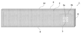
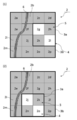
- FIG. 1 is an external view of an operation display panel built-in article on which the display device of Example 1 is mounted.
- the operation display panel built-in article 1 is covered with the protruding plate 8 in a front view, and thus has a shape as if it is a single wooden board.
- An operation display panel unit 14 is provided inside the operation display panel built-in article 1.
- the display unit 2 displays information necessary for the user (not shown) such as characters and graphics.
- a two-dimensional code display area 3a is provided in the display unit 2, and the two-dimensional code 3 is displayed in the two-dimensional code display area 3a.
- the two-dimensional code display area 3a is not fixed at the substantially right end in the display unit 2, but can be set at a free position depending on the usage form within the display unit 2. Therefore, for example, as long as the two-dimensional code 3 is displayed when the user touches any part of the display unit 2, the two-dimensional code 3 may be displayed at a part touched by the user.
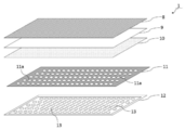
- FIG. 2 shows a configuration image diagram of an operation display panel built-in article equipped with the display device of the first embodiment.
- the operation display panel built-in article 1 includes a projecting plate 8, a transparent base material 9, a touch panel sheet 10 as a transparent conductive film, a light guide 11, and an LED array 12 as a light emitting element array. They are stacked in order.
- the projecting plate 8 is positioned on the outer surface of the operation display panel built-in article 1, and the LED array 12 is configured to be positioned inside the article.
- a Sycamore material having a high transmittance of about 10% and a good appearance is used.
- a number of LED light sources 13 are two-dimensionally arranged in the LED array 12.
- the light guide 11 guides the light emission direction of each LED light source 13 in a direction perpendicular to the substrate of the LED array 12, and is provided with the same guide holes 11 a as the number of LED light sources 13.
- the LED array 12 is composed of, for example, a total of 6400 LED light sources 13 of 32 vertically and 200 horizontally.
- One LED light source is composed of a planar mounting type LED.
- a point light source is realized by the light of one LED light source, and this is regarded as one dot, and one character or design can be expressed by 8 ⁇ 8 dots or 16 ⁇ 16 dots.
- the LED light source 13 has a size of 2 mm ⁇ 2 mm and has a size of 700 to 1000 mcd (Milli Candela), for example.
- the light guide 11 plays a role of making a character or a pattern constituted by light emitted from the LED light source 13 clearly visible through the protruding plate 8. That is, when the light guides 11 are stacked on the LED array 12, a large number of guide holes 11a are arranged in accordance with the arrangement of the LED light sources 13 so that the guide holes 11a are arranged immediately above the LED light sources 13. Is provided.
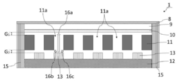
- FIG. 3 is a schematic cross-sectional view of an operation display panel built-in article on which the display device of Example 1 is mounted.
- the protruding plate 8, the transparent base material 9, the touch panel sheet 10, the light guide 11, and the LED array 12 are stacked in order from the top by the housing 15. It is glued.
- the light (16b, 16c) emitted obliquely is blocked by the light guide 11, and is projected as a straight light like the light 16a. Will reach 8.
- the housing 15 is mainly formed of ABS resin.
- the protruding plate 8 and the transparent substrate 9 or the transparent substrate 9 and the touch panel sheet 10 are bonded together without providing a gap.
- a gap G 1 is provided between the touch panel sheet 10 and the light guide 11. This is because the light guide 11 is provided with a guide hole 11a, and if the touch panel sheet 10 and the light guide 11 are bonded, the stress varies when the touch panel is operated, which may cause a malfunction. .
- a gap G 2 is also provided between the light guide 11 and the LED light source 13. Since the number of the LED light sources 13 provided in the LED array 12 and the guide holes 11a provided in the light guide 11 reaches several thousand, when the light guide 11 and the LED array 12 are stacked, an arrangement error occurs. Can occur. If the light guide 11 and the LED array 12 are bonded in a state where an error has occurred, the light emitted from the LED light source 13 does not pass through the guide hole 11a, and an accurate display is not performed. Therefore by providing the gap G 2, it is possible to prevent deterioration in display quality due to the error in arrangement of the LED light source 13 and the guide hole 11a. In addition, since the display quality is maintained even if there is some error, the manufacturing becomes easy.
- the two-dimensional code 3 shown in FIG. 1 is, for example, a QR code, and is composed of two types of cells having different colors, densities, or luminances.
- a QR code When the two-dimensional code 3 is a QR code, a blank area for four cells, three cut-out symbols, and the like are provided around the two-dimensional code. However, in the following description, these are omitted for convenience of explanation. . Also, the number of display cells differs from the actual one, and will be described in a simplified manner as shown below.
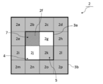
- the configuration of the display area, the movable area, and the display cell of the two-dimensional code in this embodiment will be described with reference to FIG.
- FIG. 4 is an explanatory diagram of the two-dimensional code display area and the movable area.
- the display unit 2 is provided with display cells (2a to 2p).
- the two-dimensional code display area 3a is composed of 2 ⁇ 2 in the vertical direction, and is set in the range of display cells (2f, 2g, 2j, 2k) here.
- a movable area 3b is provided with a height or width of about 50% of the two-dimensional code display area 3a in any direction, up, down, left, or right.
- a two-dimensional code display about 50% of the height H 2 of the height H 1 of the region 3a, on the two-dimensional code display region 3a, movable corresponding to display cells (2a ⁇ 2d) region 3b is provided at about 50% of the height H 3 of the height H 1 of the two-dimensional code display region 3a, under the two-dimensional code display region 3a, movable corresponding to the display cell (2m ⁇ 2p) region 3b is provided.
- each of the display cells (2a to 2p) is provided with a light emitting element, that is, an LED light source 13.
- the display cells (2a to 2p) are in the light emitting state 4 shown in white or the non-light emitting state 5 shown in gray depending on the two-dimensional code to be displayed.
- the display cell (2f, 2k) is in the light emitting state 4 and the display cell (2g, 2j) is in the non-light emitting state 5.
- the display cell (2f, 2k) in the light emitting state 4 is recognized as white
- the display cell (2g, 2j) in the non-light emitting state 5 is recognized as black.
- the configurations of the two-dimensional code display area and the movable area shown in FIG. 4 are the same in the second embodiment described later.
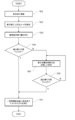
- FIG. 5 is a flowchart of the display method according to the first embodiment.
- the user contacts the display unit 2 (step S01), and the two-dimensional code 3 is displayed on the display unit 2 (step S02).
- a method of displaying the two-dimensional code 3 in addition to the method of contacting the display unit 2, a method of transmitting data from the outside, a method of operating a switch provided on the operation display panel built-in article 1, or an external An infrared sensor or the like may be used.
- the user reads the displayed two-dimensional code 3 using a camera-equipped mobile phone or the like (not shown) (step S03). Whether the reading is successful or not is judged by the user himself, and when a reading error occurs, a method of operating a switch provided on the operation display panel built-in article 1 is used. Even if a slight error occurs during reading, reading is possible as long as it is within the range of error correction capability. Even in such a case, when the reading is completed, the display is not changed, and the light emitting element dot matrix is turned off after a predetermined time (step S07).
- FIG. 6 shows a display image diagram of the two-dimensional code before using the display method of the first embodiment.
- the display cells (2f, 2k) are in the light emitting state 4, and the display cells (2g, 2j) are in the non-light emitting state 5.
- the grain 6 of the protruding plate 8 overlaps the display cell of the display unit 2.
- the display cell 2f It becomes difficult to read the light emission state 4 with a user terminal or the like. In such a case, the display is adjusted by movement or rotation.
- FIG. 7 and 8 are two-dimensional code display image diagrams when the display method of the first embodiment is used.
- FIG. 7A shows a state in which the two-dimensional code display area is moved rightward
- FIG. 8 shows a state rotated 90 ° to the right.
- the two-dimensional code display area 3a moves rightward from the range of the display cells (2f, 2g, 2j, 2k) to the range of the display cells (2g, 2h, 2k, 2l). doing.
- the two-dimensional code display area 3a does not overlap with the grain 6, and the state in which it is difficult to read the light emission state 4 of the display cell 2f is eliminated. Further, as shown in FIG.
- the two-dimensional code display area 3a is moved downward from the range of the display cells (2f, 2g, 2j, 2k) to the range of the display cells (2j, 2k, 2n, 2o). Has moved to.
- the two-dimensional code display area 3a does not overlap with the grain 6, and the state in which it is difficult to read the light emission state 4 of the display cell 2f is eliminated. In this way, it is possible to make a readable state even when moving rightward or downward.
- an arbitrary method can be used, such as selecting a position in advance, but it is preferable that the moving direction is displayed at any position within the movable region 3b. This is because as the number of display patterns increases, the reading accuracy improves.
- the two-dimensional code display area 3a remains in the range of the display cells (2f, 2g, 2j, 2k), but the display cell 2f Since the non-light-emitting state 5 is set, the state where it is difficult to read the light-emitting state 4 of the display cell 2f without overlapping the grain 6 is eliminated.
- the rotation of the two-dimensional code 3 may be used together with the movement of the two-dimensional code 3.
- the light emitting element dot matrix is turned off after a predetermined time has elapsed (step S07).
- a predetermined time By turning off the light after a certain period of time, it is possible to minimize the deterioration of the atmosphere of the place where the display is performed.
- the method of operating a switch provided on the operation display panel built-in article 1 or an external infrared sensor may be used as a trigger.
- FIG. 9 shows a flowchart of the display method of the second embodiment.
- the defect of the light emitting element dot matrix is monitored by measuring the amount of current (step S11). In such a state, the user contacts the display unit 2 (step S12). Even if the LED light source 13 is partially broken, reading is possible as long as it is within the range of error correction capability. If there is no ball break exceeding the error correction capability range (step S13), the displayed two-dimensional code is within the error correction capability range (step S16), so the two-dimensional code is displayed on the display unit. (Step S17), read by a portable terminal or the like (Step S18), and after a predetermined time elapses, the light emitting element dot matrix is turned off (Step S19).
- FIG. 10 shows a display image diagram of a two-dimensional code before using the display method of the second embodiment.
- the display cell (2f, 2k) is in the light emitting state 4, and the display cell (2g, 2g, 2j) needs to be in the non-light emitting state 5.
- the display cell (2f, 2k) is in the light emitting state 4, and the display cell (2g, 2g, 2j) needs to be in the non-light emitting state 5.
- FIG. 4 (2) in order to display the two-dimensional code 3 originally, in the two-dimensional code display area 3a, the display cell (2f, 2k) is in the light emitting state 4, and the display cell (2g, 2g, 2j) needs to be in the non-light emitting state 5.
- FIG. 4 (2) in order to display the two-dimensional code 3 originally, in the two-dimensional code display area 3a, the display cell (2f, 2k) is in the light emitting state 4, and the display cell (2g, 2g, 2j) needs to be in the non-light emitting
- the display cell 2 f is in a broken ball state 7 in the two-dimensional code display region 3 a. Therefore, the display cell 2 f is substantially in the same state as the non-light emitting state 5. Even in such a case, it is possible to read the two-dimensional code 3 within the range of the error correction capability of the two-dimensional code. However, if the error correction capability of the two-dimensional code is exceeded, the display cell 2f It becomes difficult to read the light emission state 4 with a user terminal or the like. In such a case, the display is adjusted by movement or rotation.
- FIG. 11 and 12 are two-dimensional code display image diagrams when the display method of the first embodiment is used.
- FIG. 11 (1) shows a state in which the two-dimensional code display area is moved rightward
- FIG. 11 (2) Indicates a state of moving leftward
- FIG. 12 shows a state rotated 90 ° to the right.
- the two-dimensional code display area 3a moves rightward from the range of the display cells (2f, 2g, 2j, 2k) to the range of the display cells (2g, 2h, 2k, 2l). doing.
- the two-dimensional code display area 3a is out of the area of the display cell 2f that is in the ball-out state 7, and the state in which the light emission state 4 is difficult to read is eliminated.
- the two-dimensional code display area 3a is moved leftward from the display cell (2f, 2g, 2j, 2k) to the display cell (2e, 2f, 2i, 2j). Has moved to.
- the display cell (2e, 2j) is in the light emitting state 4
- the display cell 2i is in the non-light emitting state 5
- the display cell 2f is in the out-of-bulb state 7, which is substantially the same as the non-light emitting state 5.
- the difficult situation has been resolved. In this way, it is possible to obtain a readable state even when moving in either the left or right direction.
- the two-dimensional code display area 3a remains in the range of the display cells (2f, 2g, 2j, 2k), but the display cell 2f Even in the out-of-sphere state 7, since it is the same as the non-light-emitting state 5, the state in which the light-emitting state 4 is difficult to read is eliminated.
- the movement and rotation of the two-dimensional code 3 can be performed a plurality of times, and may be used together.
- the two-dimensional code 3 is placed at any position and orientation within the movable region 3b. By changing and displaying, a display pattern increases and reading accuracy improves.
- step S15 By moving or rotating the display position of the two-dimensional code 3, it is possible to minimize the influence of the ball break (step S15), and when the two-dimensional code to be displayed is within the error correction capability range (step S16).
- the two-dimensional code 3 is displayed on the display unit 2 (step S17), read by a portable terminal or the like (step S18), and the light emitting element dot matrix is extinguished after a predetermined time has elapsed (step S19).
- step S16 when the two-dimensional code to be displayed exceeds the range of the error correction capability (step S16), it is displayed on the display unit 2 that the two-dimensional code cannot be displayed (step S20).
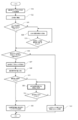
- FIG. 13 is a flowchart of the display method according to the third embodiment. As shown in FIG. 13, first, the defect of the light emitting element dot matrix is monitored by measuring the amount of current (step S21). In such a state, the user contacts the display unit 2 (step S22).
- step S23 If there is no ball break exceeding the range of error correction capability (step S23), it can be said that the two-dimensional code to be displayed is within the range of error correction capability (step S26), so the two-dimensional code is displayed on the display unit. (Step S27), read by a portable terminal or the like (Step S28).
- step S23 if there is a ball break exceeding the range of the error correction capability (step S23), the display position is adjusted by moving or rotating the display position of the two-dimensional code 3 (step S24). The movement or rotation of the display position of the two-dimensional code 3 can minimize the influence due to the ball break (step S25). If the two-dimensional code to be displayed is within the error correction capability (step S26). The two-dimensional code 3 is displayed on the display unit 2 (step S27), and is read by a portable terminal or the like (step S28). On the other hand, when the two-dimensional code to be displayed exceeds the range of the error correction capability (step S26), it is displayed on the display unit 2 that the two-dimensional code cannot be displayed (step S33). ).
- Reading is performed with a portable terminal or the like (step S28), and when the reading is completed (step S29), no further display change is performed, and the light emitting element dot matrix is turned off after a predetermined time has elapsed (step S32).
- the display position of the two-dimensional code 3 is moved or rotated to display (step S30).
- the movement / rotation here may be performed a plurality of times, or may be performed in combination with the movement / rotation. However, the movement / rotation is performed within the range of the error correction capability for the above-described ball breakage.
- step S23 The determination as to whether it is within the range of the error correction capability is made at step S23, step S26, and step S29.
- the determination in step S29 is a reading device such as a mobile phone, whereas the determination is made inside the operation display panel built-in article 1 without using a reading device such as a mobile phone.
- the user himself or herself determines whether the reading is successful or not, and the user operates a switch provided on the operation display panel built-in article 1.
- the present invention is useful as a method for displaying a two-dimensional code that is harmonized with buildings and furniture and does not impair the texture of the space. It can also be used in a payment system using a two-dimensional code.
Abstract
Provided are a display method and a display device with which the display performance of a two-dimensional code can be improved in a display panel that can be used without damaging the texture of a space. When a display fault occurs in a display panel in which a thin layer, comprising a naturally-derived wood, a natural fiber, a natural leather, or a natural stone, or comprising a synthetic fiber, a synthetic leather, or a synthetic stone that is a raw material produced by imitating a natural appearance and feel, is provided on the peripheral surface of a housing so as to be in contact with the panel front surface, a two-dimensional code is corrected by being moved or rotated and is displayed.
Description
本発明は、自然由来の素材等から成る薄層が筐体の外周面に組込まれた発光素子マトリクス上に、二次元コードを表示させる表示方法及び表示装置に関するものである。
The present invention relates to a display method and a display device for displaying a two-dimensional code on a light emitting element matrix in which a thin layer made of a natural material or the like is incorporated on the outer peripheral surface of a casing.
近年、QRコードをはじめとする二次元コードが多く用いられている(例えば、特許文献1を参照。)。例えば、ある商品を宣伝する際に、その商品を紹介するインターネットサイトへの誘導を行うために、新聞や雑誌といった紙媒体に二次元コードを印刷し、ユーザの所持する携帯端末でこれを読み取らせるといった利用方法がある。
二次元コードの表示媒体としては、紙などの印刷媒体のみならず、パーソナルコンピュータ等のディスプレイを利用することも可能であり、ディスプレイに表示された二次元コードを携帯電話等に設けられたカメラで読み取らせるといった方法が多く用いられている。 In recent years, two-dimensional codes such as QR codes are often used (see, for example, Patent Document 1). For example, when a product is advertised, a two-dimensional code is printed on a paper medium such as a newspaper or magazine in order to be guided to an Internet site that introduces the product, and is read by a portable terminal owned by the user. There are usage methods.
As a display medium for the two-dimensional code, not only a print medium such as paper but also a display such as a personal computer can be used. The two-dimensional code displayed on the display is a camera provided on a mobile phone or the like. Many methods such as reading are used.
このように、二次元コードは多方面で、多種多様に利用されていることから、その利用シーンによっては、紙媒体や液晶ディスプレイでの表示が適さない場合も存在する。
例えば、美術館において、展示物の傍に二次元コードが表示されていれば、来場者に対して展示物のより詳細な情報を載せたWebサイトへの誘導を容易に行うことができる。これにより、来場者は、単に作品を鑑賞するだけではなく、作者に関する情報や、その作品の背後にあるストーリーなどに触れることもでき、より一層その作品を楽しめることとなる。
そこで、紙媒体に二次元コードを印刷し、それぞれの作品の傍に貼り付けておくといった方法が考えられる。
しかしながら、かかる方法では、表示内容を更新するためには、紙媒体を貼り直さなければならず、煩雑であるといった問題がある。 As described above, since the two-dimensional code is used in various fields and variously, there is a case where display on a paper medium or a liquid crystal display is not suitable depending on the usage scene.
For example, in a museum, if a two-dimensional code is displayed beside an exhibit, the visitor can be easily guided to a Web site on which more detailed information on the exhibit is placed. As a result, visitors can not only appreciate the work but also touch the information about the author and the story behind the work, and enjoy the work even more.
Therefore, it is conceivable to print a two-dimensional code on a paper medium and paste it on the side of each work.
However, in this method, in order to update the display contents, there is a problem that the paper medium has to be pasted again, which is complicated.
これに対して、作品の傍に液晶ディスプレイ等を設置して、ディスプレイ上に二次元コードを表示する方式を採れば、表示内容の更新は容易にできることとなる。しかしながら、液晶ディスプレイの表示では、読み取りのためにある程度の輝度を確保する必要があるところ、美術館内の照明の方法や程度は展示内容によって異なるため、展示場所の雰囲気を考慮すると、十分な輝度を確保できない恐れがある。また、一般に液晶ディスプレイは無機質な形態を呈しているため、必ずしも展示場所の雰囲気に馴染むとはいえない。
On the other hand, if a liquid crystal display or the like is installed near the work and a two-dimensional code is displayed on the display, the display contents can be easily updated. However, when displaying on a liquid crystal display, it is necessary to ensure a certain level of brightness for reading.However, the lighting method and level in the museum vary depending on the contents of the exhibition. There is a fear that it cannot be secured. In general, a liquid crystal display has an inorganic form, so it cannot always be adapted to the atmosphere of the exhibition place.
そこで、液晶ディスプレイ等とは異なり、表示装置の表面が、木材などの自然由来の素材で形成されていれば、その場の雰囲気に馴染みやすく、美術品等の鑑賞の妨げにはなりにくいといえる。しかしながら、例えば、木材の場合には木目があるように、自然由来の素材は材質にばらつきが多いため、二次元コードの表示が不鮮明や不正確になりやすく、読み取りエラーが生じやすいといった問題がある。
Therefore, unlike a liquid crystal display or the like, if the surface of the display device is made of a natural material such as wood, it will be easy to become familiar with the atmosphere of the place and not to hinder the appreciation of artworks. . However, for example, in the case of wood, there are many variations in materials of naturally derived materials, so that there is a problem that the display of the two-dimensional code tends to be unclear or inaccurate, and reading errors are likely to occur. .
また、二次元コードに限らず、自然由来の素材を表面に用いた表示装置においては、文字等の表示についても不鮮明になる場合が考えられる。
In addition, not only the two-dimensional code but also a display device using a naturally-derived material on the surface may display characters and the like unclearly.
かかる状況に鑑みて、本発明は、空間の質感を損なうことなく利用できる表示パネルにおいて、二次元コードの表示性能を向上させることができる表示方法及び表示装置を提供することを目的とする。
In view of such a situation, an object of the present invention is to provide a display method and a display device capable of improving the display performance of a two-dimensional code in a display panel that can be used without impairing the texture of the space.
上記課題を解決すべく、本発明の二次元コードの表示方法は、自然由来の木材、天然繊維、天然皮革もしくは天然石材、又は、自然の外観と手触りを模倣して生成された素材である合成繊維、合成皮革もしくは人工石から成る薄層が、パネル前面に当接するように、筐体の外周面に配設された表示パネルの表示方法であって、表示不良が生じた場合に、二次元コードを移動又は回転させることで補正を行い表示するものである。
In order to solve the above problems, the two-dimensional code display method of the present invention is a natural wood, natural fiber, natural leather, or natural stone, or a synthetic material that is generated by imitating natural appearance and touch. A display method for a display panel arranged on the outer peripheral surface of a housing so that a thin layer made of fiber, synthetic leather, or artificial stone is in contact with the front surface of the panel. The code is corrected and displayed by moving or rotating the code.
自然由来の素材等を用いることで、その場の空間に調和し、雰囲気を損ねることなく、二次元コードを表示させることができ、表示の必要がない場合には、消灯しておくことも可能である。また、表示不良が生じた場合に、二次元コードを移動又は回転させて補正することにより、表示性能を向上させることができる。
ここで、二次元コードとは、水平方向と垂直方向に情報を持つコードのことである。二次元コードの例としては、QRコード(登録商標)が好適である。
なお、表示する二次元コードの更新方法については、表示装置が外部と通信する、近距離無線通信(NFC:Near Field Communication)で書き込む等の方法が考えられる。 By using naturally derived materials, etc., it is possible to display 2D codes in harmony with the space of the place, without damaging the atmosphere, and it is also possible to turn off the lights when there is no need for display It is. In addition, when a display defect occurs, display performance can be improved by correcting by moving or rotating the two-dimensional code.
Here, the two-dimensional code is a code having information in the horizontal direction and the vertical direction. As an example of the two-dimensional code, a QR code (registered trademark) is suitable.
As a method for updating the two-dimensional code to be displayed, a method in which the display device communicates with the outside or a method of writing by near field communication (NFC) can be considered.
第1の観点の二次元コードの表示方法において、表示不良とは、薄層を構成する素材のばらつきによる表示の不鮮明であり、補正は、下記ステップにより行われる。
1)表示パネルの表示部に、二次元コードを表示するステップ(表示ステップ)、
2)表示の不鮮明を検出するステップ(検出ステップ)、
3)二次元コードを移動又は回転させて表示の調整を行うステップ(調整ステップ)。 In the two-dimensional code display method according to the first aspect, display failure is unclear display due to variations in materials constituting the thin layer, and correction is performed by the following steps.
1) a step (display step) of displaying a two-dimensional code on the display unit of the display panel;
2) a step of detecting unclear display (detection step);
3) A step of adjusting the display by moving or rotating the two-dimensional code (adjustment step).
素材のばらつきとは、木材の木目や、繊維の太さ、皮革の厚みなどのことである。
補正については、一般に二次元コードにはエラー訂正能力が備わっており、例えば、QRコードの場合のエラー訂正能力は約7~30%である。エラー訂正能力を高めると、その分、データサイズも大きくなるという問題がある。表示の不鮮明を検出するステップは、上記のエラー訂正能力の範囲を超えた表示エラーが存在する場合に行われる。
表示ステップにおいて、二次元コードを表示させる方法としては、例えば、表示部に接触する方法、外部からのデータ送信による方法、操作表示パネル組込物品に設けられたスイッチを操作する方法、又は、外部の赤外線センサ等を利用する方法などが挙げられる。
検出ステップにおいて、読み取りの成否は、例えば、ユーザ自身が判断し、読み取りエラーとなった場合には、操作表示パネル組込物品に設けられたスイッチを操作する方法が用いられる。
調整ステップは、エラー訂正能力の範囲を超え、読み取りが完了しなかった場合に行うものであり、二次元コードの表示位置を移動又は回転して表示を行う。移動及び回転は一度だけではなく、複数回行うことができ、また、移動及び回転は何れか一方のみに限られず、両者を併用することでもよい。なお、補正のために回転を行うのは、例えば、QRコードの場合には、3つの切り出しシンボルが設けられることにより、QRコードが回転して表示されても読み取り可能となっているからである。
なお、調整ステップにおける読み取りの成否についても、検出ステップと同様に、例えば、ユーザ自身が判断し、読み取りエラーとなった場合には、操作表示パネル組込物品に設けられたスイッチを操作する方法が用いられる。 The material variation is the wood grain, fiber thickness, leather thickness, and the like.
As for correction, generally, a two-dimensional code has an error correction capability. For example, an error correction capability in the case of a QR code is about 7 to 30%. When the error correction capability is increased, there is a problem that the data size increases accordingly. The step of detecting unclear display is performed when there is a display error that exceeds the range of the error correction capability.
In the display step, as a method of displaying the two-dimensional code, for example, a method of touching the display unit, a method of data transmission from the outside, a method of operating a switch provided on the operation display panel built-in article, or an external And a method using an infrared sensor or the like.
In the detection step, the success or failure of reading is judged by the user himself. For example, when a reading error occurs, a method of operating a switch provided on the operation display panel built-in article is used.
The adjustment step is performed when the error correction capability is exceeded and the reading is not completed, and the display is performed by moving or rotating the display position of the two-dimensional code. The movement and rotation can be performed not only once but a plurality of times, and the movement and rotation are not limited to either one, and both may be used together. The reason why the rotation is performed for correction is that, for example, in the case of a QR code, three cutout symbols are provided so that the QR code can be read even if it is rotated and displayed. .
As for the success or failure of reading in the adjustment step, for example, when the user himself / herself makes a reading error as in the detection step, there is a method of operating a switch provided on the operation display panel built-in article. Used.
なお、補正後については、一定時間の経過により、自動的に消灯することでもよい。これにより、表示を行う場所の雰囲気を損ねることを最小限に留めることが可能となる。その場合、消灯方法としては、時間経過により自動的に消灯する方式の他、表示装置に設けられたスイッチを操作する方法や外部の赤外線センサ等をトリガーとしてもよい。
In addition, after the correction, the light may be automatically turned off after a certain period of time. As a result, it is possible to minimize the deterioration of the atmosphere of the place where the display is performed. In that case, as a light-off method, a method of operating a switch provided in the display device, an external infrared sensor, or the like may be used as a trigger in addition to a method of automatically turning off the light with time.
第2の観点の二次元コードの表示方法において、表示不良とは、表示パネルに設けられた発光素子の不良であり、補正は、下記ステップにより行われる。
A)発光素子の不良を監視するステップ(監視ステップ)、
B)表示要求を受けて、発光素子の不良を検出するステップ(検出ステップ)、
C)二次元コードを移動又は回転させて表示の調整を行うステップ(調整ステップ)、
D)表示パネルの表示部に、二次元コードを表示するステップ(表示ステップ)。 In the two-dimensional code display method according to the second aspect, the display failure is a failure of a light emitting element provided in the display panel, and correction is performed by the following steps.
A) a step of monitoring a defect of the light emitting element (monitoring step),
B) Upon receiving a display request, detecting a defect of the light emitting element (detection step),
C) a step of adjusting the display by moving or rotating the two-dimensional code (adjustment step),
D) A step of displaying the two-dimensional code on the display unit of the display panel (display step).
発光素子の不良としては、表示パネルに用いられるLED光源の球切れなどが挙げられる。
監視ステップは、表示パネルが起動している状態で常時監視してもよいが、ユーザによる操作やセンサによるユーザの検知等をトリガーとして監視を始める方式でもよい。
表示エラーは、二次元コードのエラー訂正能力を超えた場合に問題となるため、検出ステップでは、表示要求を受けた後、エラー訂正能力を超えたと判断された場合にのみ、発光素子の不良が検出される。
検出ステップにおける発光素子の不良の検出や、二次元コードを移動又は回転させての表示の調整は、ユーザによる操作等ではなく、表示パネルが設けられた装置内部で行われる。
なお、複数の素子が不良状態であった場合には、それぞれの座標と発光が必要な座標から、表示する二次元コードのエラー訂正能力を超えないように表示位置を調整する。
表示要求は、ユーザの操作によるものでもよいし、例えば、赤外線センサ等によりユーザを検知して自動で行うといったものでもよい。 As a defect of the light emitting element, a bulb of an LED light source used for a display panel is cut.
In the monitoring step, monitoring may be constantly performed in a state where the display panel is activated, but a method of starting monitoring by using a user operation or detection by the sensor as a trigger may be used.
Since the display error becomes a problem when the error correction capability of the two-dimensional code is exceeded, the detection step detects a defective light emitting element only when it is determined that the error correction capability has been exceeded after receiving a display request. Detected.
Detection of a defect of the light emitting element in the detection step and adjustment of display by moving or rotating the two-dimensional code are performed inside the apparatus provided with the display panel, not by a user operation or the like.
If a plurality of elements are in a defective state, the display position is adjusted so as not to exceed the error correction capability of the two-dimensional code to be displayed from the respective coordinates and the coordinates that require light emission.
The display request may be based on a user operation, or may be performed automatically by detecting the user with an infrared sensor or the like, for example.
第3の観点の二次元コードの表示方法において、表示不良とは、薄層を構成する素材のばらつきによる表示の不鮮明、又は、表示パネルに設けられた発光素子の不良の少なくとも何れかであり、補正は、下記ステップにより行われる。
a)発光素子の不良を監視するステップ(監視ステップ)、
b)表示要求を受けて、発光素子の不良を検出するステップ(発光素子不良検出ステップ)、
c)二次元コードを移動又は回転させて表示の調整を行う第1の調整ステップ、
d)表示パネルの表示部に、二次元コードを表示するステップ(表示ステップ)、
e)表示の不鮮明を検出するステップ(表示不鮮明検出ステップ)、
f)二次元コードを移動又は回転させて表示の調整を行う第2の調整ステップ。 In the display method of the two-dimensional code of the third aspect, the display failure is at least one of display blur due to variations in the material constituting the thin layer, or a failure of the light emitting element provided in the display panel, The correction is performed by the following steps.
a) a step of monitoring a defect of the light emitting element (monitoring step);
b) receiving a display request and detecting a defect of the light emitting element (light emitting element defect detecting step);
c) a first adjustment step for adjusting the display by moving or rotating the two-dimensional code;
d) a step of displaying the two-dimensional code on the display unit of the display panel (display step);
e) a step of detecting display blur (display blur detection step);
f) A second adjustment step for adjusting the display by moving or rotating the two-dimensional code.
上記方法によれば、表示不良が、薄層を構成する素材のばらつきによる表示の不鮮明と、表示パネルに設けられた発光素子の不良の何れの原因によるものであっても補正することができ、表示性能を向上させることができる。
第3の観点の二次元コードの表示方法は、第1の観点の二次元コードの表示方法と第2の観点の二次元コードの表示方法を併用するものであるが、用いる順序はこの限りでなく、第2の観点の二次元コードの表示方法を用いた後に、第1の観点の二次元コードの表示方法を用いるものでもよい。 According to the above method, the display failure can be corrected regardless of whether the display is unclear due to variations in the material constituting the thin layer or the light emitting element provided in the display panel is defective. Display performance can be improved.
The two-dimensional code display method according to the third aspect uses both the two-dimensional code display method according to the first aspect and the two-dimensional code display method according to the second aspect. Alternatively, the two-dimensional code display method according to the first aspect may be used after the two-dimensional code display method according to the second aspect.
本発明の二次元コードの表示方法は、二次元コードの移動を行うために、表示部の上下又は左右の少なくとも何れかに、二次元コードの高さ又は幅に対して、それぞれ40~60%の移動可能領域が設けられたことが好ましい。
二次元コードは、その種類によっては、既定の余白領域が設けられることが必須となっている。したがって、ここでの二次元コードの高さ又は幅とは、余白領域が設けられる場合には、余白領域を含む二次元コード全体の高さ又は幅であり、余白領域が設けられない場合には、余白領域のない二次元コードの高さ又は幅を意味する。 According to the two-dimensional code display method of the present invention, in order to move the two-dimensional code, 40 to 60% of the height or width of the two-dimensional code is provided on at least one of the top and bottom or the left and right of the display unit. It is preferable that a movable area is provided.
Depending on the type of the two-dimensional code, it is essential that a predetermined blank area is provided. Therefore, the height or width of the two-dimensional code here is the height or width of the entire two-dimensional code including the blank area when a blank area is provided, and when the blank area is not provided. , Which means the height or width of a two-dimensional code without a blank area.
本発明の二次元コードの表示装置は、自然由来の木材、天然繊維、天然皮革もしくは天然石材、又は、自然の外観と手触りを模倣して生成された素材である合成繊維、合成皮革もしくは人工石から成る薄層が、パネル前面に当接するように、筐体の外周面に配設された表示パネルにおいて、表示不良が生じた場合に、二次元コードを移動又は回転させることで補正を行い表示する手段を備える。
本発明の二次元コードの表示装置には、表示装置が外部と通信する、近距離無線通信で書き込む等により表示する二次元コードを更新する手段が設けられてもよい。 The two-dimensional code display device of the present invention is a natural-derived wood, natural fiber, natural leather or natural stone material, or a synthetic fiber, synthetic leather or artificial stone which is a material generated by imitating natural appearance and touch When a display failure occurs on the display panel arranged on the outer peripheral surface of the housing so that the thin layer consisting of the touches the front of the panel, the display is corrected and moved by moving or rotating the two-dimensional code. Means are provided.
The two-dimensional code display device of the present invention may be provided with means for updating the two-dimensional code displayed by the display device communicating with the outside, writing by short-range wireless communication, or the like.
第1の観点の二次元コードの表示装置において、表示不良とは、薄層を構成する素材のばらつきによる表示の不鮮明であり、補正手段は、表示パネルの表示部に、二次元コードを表示する手段と、表示の不鮮明を検出する手段と、二次元コードを移動又は回転させて表示の調整を行う手段から成る。
In the two-dimensional code display device according to the first aspect, display failure is unclear display due to variations in the material constituting the thin layer, and the correcting means displays the two-dimensional code on the display unit of the display panel. Means for detecting blurring of display, and means for adjusting display by moving or rotating the two-dimensional code.
第2の観点の二次元コードの表示装置において、表示不良とは、表示パネルに設けられた発光素子の不良であり、補正手段は、発光素子の不良を監視する手段と、表示要求を受けて、発光素子の不良を検出する手段と、二次元コードを移動又は回転させて表示の調整を行う手段と、表示パネルの表示部に、二次元コードを表示する手段から成る。
In the two-dimensional code display device according to the second aspect, the display defect is a defect of a light emitting element provided in the display panel, and the correction means receives a display request and means for monitoring the defect of the light emitting element. , A means for detecting a defect of the light emitting element, a means for adjusting the display by moving or rotating the two-dimensional code, and a means for displaying the two-dimensional code on the display unit of the display panel.
第3の観点の二次元コードの表示装置において、表示不良とは、薄層を構成する素材のばらつきによる表示の不鮮明、又は、表示パネルに設けられた発光素子の不良の少なくとも何れかであり、補正手段は、発光素子の不良を監視する手段と、表示要求を受けて、発光素子の不良を検出する手段と、二次元コードを移動又は回転させて表示の調整を行う第1の調整手段と、表示パネルの表示部に、二次元コードを表示する手段と、表示の不鮮明を検出する手段と、二次元コードを移動又は回転させて表示の調整を行う第2の調整手段から成る。
In the display device of the two-dimensional code of the third aspect, the display failure is at least one of display blur due to variations in the material constituting the thin layer, or a failure of the light emitting element provided in the display panel, The correcting means is means for monitoring the defect of the light emitting element, means for detecting the defect of the light emitting element in response to the display request, and a first adjusting means for adjusting the display by moving or rotating the two-dimensional code. The display unit of the display panel includes means for displaying a two-dimensional code, means for detecting unclear display, and second adjustment means for adjusting display by moving or rotating the two-dimensional code.
本発明の二次元コードの表示装置は、二次元コードの移動を行うために、表示部の上下又は左右の少なくとも何れかに、二次元コードの高さ又は幅に対して、それぞれ40~60%の移動可能領域が設けられたことが好ましい。
The two-dimensional code display device according to the present invention is 40 to 60% of the height or width of the two-dimensional code on at least one of the top and bottom or the left and right of the display unit in order to move the two-dimensional code. It is preferable that a movable area is provided.
本発明の二次元コードの表示方法及び表示装置によれば、自然由来の素材等を表面に用いることから、空間内に溶け込み、その空間の質感を損なうことなく利用できるといった効果がある。また、表示不良を補正できるため、表示性能を向上させることができるといった効果がある。
According to the two-dimensional code display method and display device of the present invention, since a naturally-derived material or the like is used for the surface, there is an effect that it can be used without damaging the texture of the space. In addition, since display defects can be corrected, there is an effect that display performance can be improved.
以下、本発明の実施形態の一例を、図面を参照しながら詳細に説明していく。なお、本発明の範囲は、以下の実施例や図示例に限定されるものではなく、幾多の変更及び変形が可能である。
Hereinafter, an example of an embodiment of the present invention will be described in detail with reference to the drawings. The scope of the present invention is not limited to the following examples and illustrated examples, and many changes and modifications can be made.
(操作表示パネル組込物品の構造について)
図1は、実施例1の表示装置を搭載した操作表示パネル組込物品の外観図を示している。図1に示すように、操作表示パネル組込物品1は、正面視上では、突板8に覆われているため、あたかも1枚の木板であるかのような形状を呈している。操作表示パネル組込物品1の内部には、操作表示パネルユニット14が設けられている。
表示部2には、文字や図形等、ユーザ(図示せず)にとって必要となる情報が表示される。表示部2内には、二次元コード表示領域3aが設けられており、二次元コード表示領域3aには、二次元コード3が表示されている。二次元コード表示領域3aは、表示部2内の略右端に固定されるわけではなく、表示部2内であれば、利用形態によって自由な位置に設定することが可能である。したがって、例えば、ユーザが表示部2の任意の箇所をタッチすることで二次元コード3が表示される方式であれば、ユーザがタッチした箇所に二次元コード3が表示されてもよい。 (About the structure of the operation display panel built-in article)
FIG. 1 is an external view of an operation display panel built-in article on which the display device of Example 1 is mounted. As shown in FIG. 1, the operation display panel built-inarticle 1 is covered with the protruding plate 8 in a front view, and thus has a shape as if it is a single wooden board. An operation display panel unit 14 is provided inside the operation display panel built-in article 1.
Thedisplay unit 2 displays information necessary for the user (not shown) such as characters and graphics. A two-dimensional code display area 3a is provided in the display unit 2, and the two-dimensional code 3 is displayed in the two-dimensional code display area 3a. The two-dimensional code display area 3a is not fixed at the substantially right end in the display unit 2, but can be set at a free position depending on the usage form within the display unit 2. Therefore, for example, as long as the two-dimensional code 3 is displayed when the user touches any part of the display unit 2, the two-dimensional code 3 may be displayed at a part touched by the user.
図1は、実施例1の表示装置を搭載した操作表示パネル組込物品の外観図を示している。図1に示すように、操作表示パネル組込物品1は、正面視上では、突板8に覆われているため、あたかも1枚の木板であるかのような形状を呈している。操作表示パネル組込物品1の内部には、操作表示パネルユニット14が設けられている。
表示部2には、文字や図形等、ユーザ(図示せず)にとって必要となる情報が表示される。表示部2内には、二次元コード表示領域3aが設けられており、二次元コード表示領域3aには、二次元コード3が表示されている。二次元コード表示領域3aは、表示部2内の略右端に固定されるわけではなく、表示部2内であれば、利用形態によって自由な位置に設定することが可能である。したがって、例えば、ユーザが表示部2の任意の箇所をタッチすることで二次元コード3が表示される方式であれば、ユーザがタッチした箇所に二次元コード3が表示されてもよい。 (About the structure of the operation display panel built-in article)
FIG. 1 is an external view of an operation display panel built-in article on which the display device of Example 1 is mounted. As shown in FIG. 1, the operation display panel built-in
The
次に、操作表示パネル組込物品の内部構造について説明する。図2は、実施例1の表示装置を搭載した操作表示パネル組込物品の構成イメージ図を示している。図2に示すように、操作表示パネル組込物品1は、突板8、透明基材9、透明導電膜としてタッチパネルシート10、ライトガイド11及び発光素子アレイとしてLEDアレイ12から構成され、それぞれ上から順に積層されている。
突板8は、操作表示パネル組込物品1の外表面に位置し、LEDアレイ12は物品内部に位置するように構成される。突板8の材質としては、透過率が10%程度と高く、しかも見栄えが良いシカモア材を用いている。
LEDアレイ12には多数のLED光源13が二次元に配列されている。ライトガイド11は、各LED光源13の光の射出方向をLEDアレイ12の基板と垂直方向に導くものであり、LED光源13の個数と同じガイド孔11aが設けられている。 Next, the internal structure of the operation display panel built-in article will be described. FIG. 2 shows a configuration image diagram of an operation display panel built-in article equipped with the display device of the first embodiment. As shown in FIG. 2, the operation display panel built-inarticle 1 includes a projecting plate 8, a transparent base material 9, a touch panel sheet 10 as a transparent conductive film, a light guide 11, and an LED array 12 as a light emitting element array. They are stacked in order.
The projectingplate 8 is positioned on the outer surface of the operation display panel built-in article 1, and the LED array 12 is configured to be positioned inside the article. As the material of the protruding plate 8, a Sycamore material having a high transmittance of about 10% and a good appearance is used.
A number ofLED light sources 13 are two-dimensionally arranged in the LED array 12. The light guide 11 guides the light emission direction of each LED light source 13 in a direction perpendicular to the substrate of the LED array 12, and is provided with the same guide holes 11 a as the number of LED light sources 13.
突板8は、操作表示パネル組込物品1の外表面に位置し、LEDアレイ12は物品内部に位置するように構成される。突板8の材質としては、透過率が10%程度と高く、しかも見栄えが良いシカモア材を用いている。
LEDアレイ12には多数のLED光源13が二次元に配列されている。ライトガイド11は、各LED光源13の光の射出方向をLEDアレイ12の基板と垂直方向に導くものであり、LED光源13の個数と同じガイド孔11aが設けられている。 Next, the internal structure of the operation display panel built-in article will be described. FIG. 2 shows a configuration image diagram of an operation display panel built-in article equipped with the display device of the first embodiment. As shown in FIG. 2, the operation display panel built-in
The projecting
A number of
図2においては、説明の都合上、全てのLED光源を図示していないが、例えば、縦32個横200個の計6400個のLED光源13でLEDアレイ12が構成される。1つのLED光源は平面実装タイプのLEDで構成される。1つのLED光源の光で点光源を実現し、これを1ドットと見て、8×8ドット、或は、16×16ドットで1つの文字や図柄を表現することができる。例えば、6400個のLED光源を有するLEDアレイ12の場合、22文字×3行の文章を表現させることができる。ここで、LED光源13は、例えば、2mm×2mmのサイズで、700~1000mcd(ミリカンデラ)のものを用いる。このようなLEDアレイ12を使って二次元コードを表示する。
ライトガイド11は、LED光源13から発せられる光で構成される文字や図柄を、突板8を通して鮮明に視認させる役割を担っている。すなわち、LEDアレイ12の上にライトガイド11が積層された際に、各LED光源13の直上にガイド孔11aが配置されるように、LED光源13の配置に合わせて、多数のガイド孔11aが設けられている。 In FIG. 2, for convenience of explanation, not all LED light sources are shown, but theLED array 12 is composed of, for example, a total of 6400 LED light sources 13 of 32 vertically and 200 horizontally. One LED light source is composed of a planar mounting type LED. A point light source is realized by the light of one LED light source, and this is regarded as one dot, and one character or design can be expressed by 8 × 8 dots or 16 × 16 dots. For example, in the case of the LED array 12 having 6400 LED light sources, a sentence of 22 characters × 3 lines can be expressed. Here, the LED light source 13 has a size of 2 mm × 2 mm and has a size of 700 to 1000 mcd (Milli Candela), for example. A two-dimensional code is displayed using such an LED array 12.
Thelight guide 11 plays a role of making a character or a pattern constituted by light emitted from the LED light source 13 clearly visible through the protruding plate 8. That is, when the light guides 11 are stacked on the LED array 12, a large number of guide holes 11a are arranged in accordance with the arrangement of the LED light sources 13 so that the guide holes 11a are arranged immediately above the LED light sources 13. Is provided.
ライトガイド11は、LED光源13から発せられる光で構成される文字や図柄を、突板8を通して鮮明に視認させる役割を担っている。すなわち、LEDアレイ12の上にライトガイド11が積層された際に、各LED光源13の直上にガイド孔11aが配置されるように、LED光源13の配置に合わせて、多数のガイド孔11aが設けられている。 In FIG. 2, for convenience of explanation, not all LED light sources are shown, but the
The
次に、操作表示パネル組込物品の組み立て後の構造について図3を参照しながら説明する。図3は、実施例1の表示装置を搭載した操作表示パネル組込物品の断面模式図を示している。図3に示すように、操作表示パネル組込物品1において、突板8、透明基材9、タッチパネルシート10、ライトガイド11及びLEDアレイ12は、筐体15によって、上から順に積層された状態で接着されている。LEDアレイ12上に設けられたLED光源13から発せられた光の内、斜めに発せられた光(16b,16c)は、ライトガイド11によって遮られ、光16aのように真っ直ぐな光として、突板8に届くこととなる。なお、筐体15は、主にABS樹脂で形成されている。
突板8と透明基材9、又は、透明基材9とタッチパネルシート10は、間隙を設けることなく、貼り合わされている。これに対して、タッチパネルシート10とライトガイド11の間には、ギャップG1が設けられている。これは、ライトガイド11にはガイド孔11aが設けられているため、タッチパネルシート10とライトガイド11を接着すると、タッチパネルを操作した際に、応力にばらつきが生じ、誤動作の原因となるためである。 Next, the structure after assembling the operation display panel built-in article will be described with reference to FIG. FIG. 3 is a schematic cross-sectional view of an operation display panel built-in article on which the display device of Example 1 is mounted. As shown in FIG. 3, in the operation display panel built-inarticle 1, the protruding plate 8, the transparent base material 9, the touch panel sheet 10, the light guide 11, and the LED array 12 are stacked in order from the top by the housing 15. It is glued. Of the light emitted from the LED light source 13 provided on the LED array 12, the light (16b, 16c) emitted obliquely is blocked by the light guide 11, and is projected as a straight light like the light 16a. Will reach 8. The housing 15 is mainly formed of ABS resin.
The protrudingplate 8 and the transparent substrate 9 or the transparent substrate 9 and the touch panel sheet 10 are bonded together without providing a gap. On the other hand, a gap G 1 is provided between the touch panel sheet 10 and the light guide 11. This is because the light guide 11 is provided with a guide hole 11a, and if the touch panel sheet 10 and the light guide 11 are bonded, the stress varies when the touch panel is operated, which may cause a malfunction. .
突板8と透明基材9、又は、透明基材9とタッチパネルシート10は、間隙を設けることなく、貼り合わされている。これに対して、タッチパネルシート10とライトガイド11の間には、ギャップG1が設けられている。これは、ライトガイド11にはガイド孔11aが設けられているため、タッチパネルシート10とライトガイド11を接着すると、タッチパネルを操作した際に、応力にばらつきが生じ、誤動作の原因となるためである。 Next, the structure after assembling the operation display panel built-in article will be described with reference to FIG. FIG. 3 is a schematic cross-sectional view of an operation display panel built-in article on which the display device of Example 1 is mounted. As shown in FIG. 3, in the operation display panel built-in
The protruding
また、ライトガイド11とLED光源13の間にも、ギャップG2が設けられている。LEDアレイ12に設けられるLED光源13や、ライトガイド11に設けられるガイド孔11aの数は、数千個にも及ぶことから、ライトガイド11とLEDアレイ12を積層した場合に、配置の誤差が生じる可能性がある。誤差が生じた状態で、ライトガイド11とLEDアレイ12を接着すると、LED光源13から発せられた光がガイド孔11aに通らず、正確な表示がなされないこととなる。そこでギャップG2を設けることにより、LED光源13とガイド孔11aの配置の誤差による表示品質の低下を防止することができる。また、多少の誤差があっても表示品質が保たれるため、製造が容易となる。
A gap G 2 is also provided between the light guide 11 and the LED light source 13. Since the number of the LED light sources 13 provided in the LED array 12 and the guide holes 11a provided in the light guide 11 reaches several thousand, when the light guide 11 and the LED array 12 are stacked, an arrangement error occurs. Can occur. If the light guide 11 and the LED array 12 are bonded in a state where an error has occurred, the light emitted from the LED light source 13 does not pass through the guide hole 11a, and an accurate display is not performed. Therefore by providing the gap G 2, it is possible to prevent deterioration in display quality due to the error in arrangement of the LED light source 13 and the guide hole 11a. In addition, since the display quality is maintained even if there is some error, the manufacturing becomes easy.
(二次元コードの表示方法について)
図1に示す二次元コード3は、例えば、QRコードであって、色彩、濃度又は輝度の異なる2種類のセルにより構成される。二次元コード3がQRコードである場合には、二次元コードの周りに4セル分の余白領域や3つの切り出しシンボルなどが設けられるが、以下では、説明の便宜上、これらを省略して説明する。また、表示セルの数についても実際のものとは異なり、以下に示すように、簡略化して説明する。本実施例における二次元コードの表示領域、移動可能領域及び表示セルの構成について、図4を参照しながら説明する。
図4は、二次元コード表示領域と移動可能領域の説明図を示している。図4(1)に示すように、表示部2には、表示セル(2a~2p)が設けられている。
二次元コード表示領域3aは、縦2×横2で構成され、ここでは表示セル(2f,2g,2j,2k)の範囲に設定されている。二次元コード表示領域3aの周りには、上下左右いずれの方向にも二次元コード表示領域3aの約50%の高さ又は幅で、移動可能領域3bが設けられている。具体的には、二次元コード表示領域3aの高さH1の約50%の高さH2で、二次元コード表示領域3aの上に、表示セル(2a~2d)に該当する移動可能領域3bが設けられ、二次元コード表示領域3aの高さH1の約50%の高さH3で、二次元コード表示領域3aの下に、表示セル(2m~2p)に該当する移動可能領域3bが設けられている。
また、二次元コード表示領域3aの幅W1の約50%の幅W2で、二次元コード表示領域3aの左に、表示セル(2a,2e,2i,2m)に該当する移動可能領域3bが設けられ、二次元コード表示領域3aの幅W1の約50%の幅W3で、二次元コード表示領域3aの右に、表示セル(2d,2h,2l,2p)に該当する移動可能領域3bが設けられている。
表示セル(2a~2p)にはそれぞれ発光素子すなわちLED光源13が設けられていることとする。したがって、表示セル(2a~2p)は、表示する二次元コードに応じて、白色で示す発光状態4又は灰色で示す非発光状態5となる。図4(2)に示す二次元コード3では、表示セル(2f,2k)は発光状態4となり、表示セル(2g,2j)は非発光状態5となっている。例えば、QRコードでは、発光状態4である表示セル(2f,2k)は白色、非発光状態5である表示セル(2g,2j)は黒色として認識されることとなる。
なお、図4に示す二次元コード表示領域と移動可能領域の構成については、後述する実施例2においても同様である。 (2D code display method)
The two-dimensional code 3 shown in FIG. 1 is, for example, a QR code, and is composed of two types of cells having different colors, densities, or luminances. When the two-dimensional code 3 is a QR code, a blank area for four cells, three cut-out symbols, and the like are provided around the two-dimensional code. However, in the following description, these are omitted for convenience of explanation. . Also, the number of display cells differs from the actual one, and will be described in a simplified manner as shown below. The configuration of the display area, the movable area, and the display cell of the two-dimensional code in this embodiment will be described with reference to FIG.
FIG. 4 is an explanatory diagram of the two-dimensional code display area and the movable area. As shown in FIG. 4A, thedisplay unit 2 is provided with display cells (2a to 2p).
The two-dimensionalcode display area 3a is composed of 2 × 2 in the vertical direction, and is set in the range of display cells (2f, 2g, 2j, 2k) here. Around the two-dimensional code display area 3a, a movable area 3b is provided with a height or width of about 50% of the two-dimensional code display area 3a in any direction, up, down, left, or right. Specifically, a two-dimensional code display about 50% of the height H 2 of the height H 1 of the region 3a, on the two-dimensional code display region 3a, movable corresponding to display cells (2a ~ 2d) region 3b is provided at about 50% of the height H 3 of the height H 1 of the two-dimensional code display region 3a, under the two-dimensional code display region 3a, movable corresponding to the display cell (2m ~ 2p) region 3b is provided.
Further, about 50% of the width W 2 of width W 1 of the two-dimensionalcode display area 3a, the left of the two-dimensional code display area 3a, the movable area 3b corresponding to display cells (2a, 2e, 2i, 2m ) is provided, at about 50% of the width W 3 of the width W 1 of the two-dimensional code display area 3a, the right of the two-dimensional code display region 3a, movable corresponding to display cells (2d, 2h, 2l, 2p ) Region 3b is provided.
It is assumed that each of the display cells (2a to 2p) is provided with a light emitting element, that is, anLED light source 13. Accordingly, the display cells (2a to 2p) are in the light emitting state 4 shown in white or the non-light emitting state 5 shown in gray depending on the two-dimensional code to be displayed. In the two-dimensional code 3 shown in FIG. 4B, the display cell (2f, 2k) is in the light emitting state 4 and the display cell (2g, 2j) is in the non-light emitting state 5. For example, in the QR code, the display cell (2f, 2k) in the light emitting state 4 is recognized as white, and the display cell (2g, 2j) in the non-light emitting state 5 is recognized as black.
The configurations of the two-dimensional code display area and the movable area shown in FIG. 4 are the same in the second embodiment described later.
図1に示す二次元コード3は、例えば、QRコードであって、色彩、濃度又は輝度の異なる2種類のセルにより構成される。二次元コード3がQRコードである場合には、二次元コードの周りに4セル分の余白領域や3つの切り出しシンボルなどが設けられるが、以下では、説明の便宜上、これらを省略して説明する。また、表示セルの数についても実際のものとは異なり、以下に示すように、簡略化して説明する。本実施例における二次元コードの表示領域、移動可能領域及び表示セルの構成について、図4を参照しながら説明する。
図4は、二次元コード表示領域と移動可能領域の説明図を示している。図4(1)に示すように、表示部2には、表示セル(2a~2p)が設けられている。
二次元コード表示領域3aは、縦2×横2で構成され、ここでは表示セル(2f,2g,2j,2k)の範囲に設定されている。二次元コード表示領域3aの周りには、上下左右いずれの方向にも二次元コード表示領域3aの約50%の高さ又は幅で、移動可能領域3bが設けられている。具体的には、二次元コード表示領域3aの高さH1の約50%の高さH2で、二次元コード表示領域3aの上に、表示セル(2a~2d)に該当する移動可能領域3bが設けられ、二次元コード表示領域3aの高さH1の約50%の高さH3で、二次元コード表示領域3aの下に、表示セル(2m~2p)に該当する移動可能領域3bが設けられている。
また、二次元コード表示領域3aの幅W1の約50%の幅W2で、二次元コード表示領域3aの左に、表示セル(2a,2e,2i,2m)に該当する移動可能領域3bが設けられ、二次元コード表示領域3aの幅W1の約50%の幅W3で、二次元コード表示領域3aの右に、表示セル(2d,2h,2l,2p)に該当する移動可能領域3bが設けられている。
表示セル(2a~2p)にはそれぞれ発光素子すなわちLED光源13が設けられていることとする。したがって、表示セル(2a~2p)は、表示する二次元コードに応じて、白色で示す発光状態4又は灰色で示す非発光状態5となる。図4(2)に示す二次元コード3では、表示セル(2f,2k)は発光状態4となり、表示セル(2g,2j)は非発光状態5となっている。例えば、QRコードでは、発光状態4である表示セル(2f,2k)は白色、非発光状態5である表示セル(2g,2j)は黒色として認識されることとなる。
なお、図4に示す二次元コード表示領域と移動可能領域の構成については、後述する実施例2においても同様である。 (2D code display method)
The two-
FIG. 4 is an explanatory diagram of the two-dimensional code display area and the movable area. As shown in FIG. 4A, the
The two-dimensional
Further, about 50% of the width W 2 of width W 1 of the two-dimensional
It is assumed that each of the display cells (2a to 2p) is provided with a light emitting element, that is, an
The configurations of the two-dimensional code display area and the movable area shown in FIG. 4 are the same in the second embodiment described later.
本実施例では、突板8の木目6がLED光源13からの光と重なることによる表示エラーを回避する表示方法について説明する。
図5は、実施例1の表示方法のフロー図を示している。図5に示すように、まず、ユーザが表示部2に接触し(ステップS01)、表示部2上に二次元コード3を表示させる(ステップS02)。二次元コード3を表示させる方法としては、表示部2に接触する方法以外にも、外部からのデータ送信による方法、操作表示パネル組込物品1に設けられたスイッチを操作する方法、又は、外部の赤外線センサ等を利用するものでもよい。
ユーザは、表示された二次元コード3をカメラ付きの携帯電話等(図示せず)を用いて読み取りを行う(ステップS03)。読み取りの成否は、ユーザ自身が判断し、読み取りエラーとなった場合には、操作表示パネル組込物品1に設けられたスイッチを操作する方法などが用いられる。なお、読み取りの際に僅かなエラーが発生したとしても、エラー訂正能力の範囲内であれば、読み取りは可能である。このような場合も含めて、読み取りが完了した場合には表示の変更は行われず、一定時間経過後に発光素子ドットマトリクスを消灯する(ステップS07)。 In this embodiment, a display method for avoiding a display error due to thegrain 6 of the protruding plate 8 overlapping the light from the LED light source 13 will be described.
FIG. 5 is a flowchart of the display method according to the first embodiment. As shown in FIG. 5, first, the user contacts the display unit 2 (step S01), and the two-dimensional code 3 is displayed on the display unit 2 (step S02). As a method of displaying the two-dimensional code 3, in addition to the method of contacting the display unit 2, a method of transmitting data from the outside, a method of operating a switch provided on the operation display panel built-in article 1, or an external An infrared sensor or the like may be used.
The user reads the displayed two-dimensional code 3 using a camera-equipped mobile phone or the like (not shown) (step S03). Whether the reading is successful or not is judged by the user himself, and when a reading error occurs, a method of operating a switch provided on the operation display panel built-in article 1 is used. Even if a slight error occurs during reading, reading is possible as long as it is within the range of error correction capability. Even in such a case, when the reading is completed, the display is not changed, and the light emitting element dot matrix is turned off after a predetermined time (step S07).
図5は、実施例1の表示方法のフロー図を示している。図5に示すように、まず、ユーザが表示部2に接触し(ステップS01)、表示部2上に二次元コード3を表示させる(ステップS02)。二次元コード3を表示させる方法としては、表示部2に接触する方法以外にも、外部からのデータ送信による方法、操作表示パネル組込物品1に設けられたスイッチを操作する方法、又は、外部の赤外線センサ等を利用するものでもよい。
ユーザは、表示された二次元コード3をカメラ付きの携帯電話等(図示せず)を用いて読み取りを行う(ステップS03)。読み取りの成否は、ユーザ自身が判断し、読み取りエラーとなった場合には、操作表示パネル組込物品1に設けられたスイッチを操作する方法などが用いられる。なお、読み取りの際に僅かなエラーが発生したとしても、エラー訂正能力の範囲内であれば、読み取りは可能である。このような場合も含めて、読み取りが完了した場合には表示の変更は行われず、一定時間経過後に発光素子ドットマトリクスを消灯する(ステップS07)。 In this embodiment, a display method for avoiding a display error due to the
FIG. 5 is a flowchart of the display method according to the first embodiment. As shown in FIG. 5, first, the user contacts the display unit 2 (step S01), and the two-
The user reads the displayed two-
これに対して、エラー訂正能力の範囲を超え、読み取りが完了しなかった場合には、二次元コード3の表示位置を移動又は回転して表示を行う(ステップS05)。ここで、表示位置の移動又は回転方法について、図6~8を参照しながら説明する。
図6は、実施例1の表示方法の使用前の二次元コードの表示イメージ図を示している。図6に示すように、二次元コード表示領域3aにおいて、表示セル(2f,2k)は発光状態4となり、表示セル(2g,2j)は非発光状態5となっている。しかしながら、表示部2の表示セル上には突板8の木目6が重なっている。このような場合でも、二次元コードのエラー訂正能力の範囲内であれば、二次元コード3を読み取ることは可能であるが、二次元コードのエラー訂正能力を超える場合には、表示セル2fの発光状態4をユーザの端末等で読み取ることが困難な状態となる。そこでかかる場合には、移動や回転による表示の調整を行う。 On the other hand, when the error correction capability is exceeded and reading is not completed, display is performed by moving or rotating the display position of the two-dimensional code 3 (step S05). Here, a method of moving or rotating the display position will be described with reference to FIGS.
FIG. 6 shows a display image diagram of the two-dimensional code before using the display method of the first embodiment. As shown in FIG. 6, in the two-dimensionalcode display area 3a, the display cells (2f, 2k) are in the light emitting state 4, and the display cells (2g, 2j) are in the non-light emitting state 5. However, the grain 6 of the protruding plate 8 overlaps the display cell of the display unit 2. Even in such a case, it is possible to read the two-dimensional code 3 within the range of the error correction capability of the two-dimensional code. However, if the error correction capability of the two-dimensional code is exceeded, the display cell 2f It becomes difficult to read the light emission state 4 with a user terminal or the like. In such a case, the display is adjusted by movement or rotation.
図6は、実施例1の表示方法の使用前の二次元コードの表示イメージ図を示している。図6に示すように、二次元コード表示領域3aにおいて、表示セル(2f,2k)は発光状態4となり、表示セル(2g,2j)は非発光状態5となっている。しかしながら、表示部2の表示セル上には突板8の木目6が重なっている。このような場合でも、二次元コードのエラー訂正能力の範囲内であれば、二次元コード3を読み取ることは可能であるが、二次元コードのエラー訂正能力を超える場合には、表示セル2fの発光状態4をユーザの端末等で読み取ることが困難な状態となる。そこでかかる場合には、移動や回転による表示の調整を行う。 On the other hand, when the error correction capability is exceeded and reading is not completed, display is performed by moving or rotating the display position of the two-dimensional code 3 (step S05). Here, a method of moving or rotating the display position will be described with reference to FIGS.
FIG. 6 shows a display image diagram of the two-dimensional code before using the display method of the first embodiment. As shown in FIG. 6, in the two-dimensional
図7及び8は、実施例1の表示方法の使用時の二次元コードの表示イメージ図であり、二次元コード表示領域につき、図7(1)は右方向に移動した状態、図7(2)は下方向に移動した状態を示している。また、図8は、右に90°回転した状態を示している。
図7(1)に示すように、二次元コード表示領域3aは、表示セル(2f,2g,2j,2k)の範囲から表示セル(2g,2h,2k,2l)の範囲に右方向に移動している。これにより、二次元コード表示領域3aは、木目6と重ならず、表示セル2fの発光状態4の読み取りが困難な状態は解消されている。
また、図7(2)に示すように、二次元コード表示領域3aは、表示セル(2f,2g,2j,2k)の範囲から表示セル(2j,2k,2n,2o)の範囲に下方向に移動している。これにより、二次元コード表示領域3aは、木目6と重ならず、表示セル2fの発光状態4の読み取りが困難な状態は解消されている。
このように、右方向又は下方向のいずれに移動した場合でも読み取り可能な状態とすることが可能である。かかる移動方向の選択については、予め順位を設けて選択する等、任意の方法が利用可能であるが、移動可能領域3bの範囲内で、あらゆる位置に変更して表示されることが好ましい。表示パターンが多くなればなるほど、読み取り精度が向上するからである。 7 and 8 are two-dimensional code display image diagrams when the display method of the first embodiment is used. FIG. 7A shows a state in which the two-dimensional code display area is moved rightward, and FIG. Indicates a state of moving downward. FIG. 8 shows a state rotated 90 ° to the right.
As shown in FIG. 7 (1), the two-dimensionalcode display area 3a moves rightward from the range of the display cells (2f, 2g, 2j, 2k) to the range of the display cells (2g, 2h, 2k, 2l). doing. As a result, the two-dimensional code display area 3a does not overlap with the grain 6, and the state in which it is difficult to read the light emission state 4 of the display cell 2f is eliminated.
Further, as shown in FIG. 7 (2), the two-dimensionalcode display area 3a is moved downward from the range of the display cells (2f, 2g, 2j, 2k) to the range of the display cells (2j, 2k, 2n, 2o). Has moved to. As a result, the two-dimensional code display area 3a does not overlap with the grain 6, and the state in which it is difficult to read the light emission state 4 of the display cell 2f is eliminated.
In this way, it is possible to make a readable state even when moving rightward or downward. For the selection of the moving direction, an arbitrary method can be used, such as selecting a position in advance, but it is preferable that the moving direction is displayed at any position within themovable region 3b. This is because as the number of display patterns increases, the reading accuracy improves.
図7(1)に示すように、二次元コード表示領域3aは、表示セル(2f,2g,2j,2k)の範囲から表示セル(2g,2h,2k,2l)の範囲に右方向に移動している。これにより、二次元コード表示領域3aは、木目6と重ならず、表示セル2fの発光状態4の読み取りが困難な状態は解消されている。
また、図7(2)に示すように、二次元コード表示領域3aは、表示セル(2f,2g,2j,2k)の範囲から表示セル(2j,2k,2n,2o)の範囲に下方向に移動している。これにより、二次元コード表示領域3aは、木目6と重ならず、表示セル2fの発光状態4の読み取りが困難な状態は解消されている。
このように、右方向又は下方向のいずれに移動した場合でも読み取り可能な状態とすることが可能である。かかる移動方向の選択については、予め順位を設けて選択する等、任意の方法が利用可能であるが、移動可能領域3bの範囲内で、あらゆる位置に変更して表示されることが好ましい。表示パターンが多くなればなるほど、読み取り精度が向上するからである。 7 and 8 are two-dimensional code display image diagrams when the display method of the first embodiment is used. FIG. 7A shows a state in which the two-dimensional code display area is moved rightward, and FIG. Indicates a state of moving downward. FIG. 8 shows a state rotated 90 ° to the right.
As shown in FIG. 7 (1), the two-dimensional
Further, as shown in FIG. 7 (2), the two-dimensional
In this way, it is possible to make a readable state even when moving rightward or downward. For the selection of the moving direction, an arbitrary method can be used, such as selecting a position in advance, but it is preferable that the moving direction is displayed at any position within the
また、図8に示すように、右に90°回転した状態においても、二次元コード表示領域3aは、表示セル(2f,2g,2j,2k)の範囲のままではあるが、表示セル2fは非発光状態5となるため、木目6と重ならず、表示セル2fの発光状態4の読み取りが困難な状態は解消されている。
二次元コード3の回転は、二次元コード3の移動と併用してもよい。移動可能領域3bの範囲内で、あらゆる位置や向きに二次元コード3を変更して表示することで、更に表示パターンが多くなり、読み取り精度が向上する。 Further, as shown in FIG. 8, even in the state rotated 90 ° to the right, the two-dimensionalcode display area 3a remains in the range of the display cells (2f, 2g, 2j, 2k), but the display cell 2f Since the non-light-emitting state 5 is set, the state where it is difficult to read the light-emitting state 4 of the display cell 2f without overlapping the grain 6 is eliminated.
The rotation of the two-dimensional code 3 may be used together with the movement of the two-dimensional code 3. By changing and displaying the two-dimensional code 3 at any position and orientation within the movable region 3b, the display pattern is further increased and the reading accuracy is improved.
二次元コード3の回転は、二次元コード3の移動と併用してもよい。移動可能領域3bの範囲内で、あらゆる位置や向きに二次元コード3を変更して表示することで、更に表示パターンが多くなり、読み取り精度が向上する。 Further, as shown in FIG. 8, even in the state rotated 90 ° to the right, the two-dimensional
The rotation of the two-
二次元コード3の表示位置の移動又は回転により、読み取りが完了した場合は、一定時間経過後に発光素子ドットマトリクスを消灯する(ステップS07)。一定時間の経過後に消灯することにより、表示を行う場所の雰囲気を損ねることを最小限に留めることが可能となる。
なお、消灯についても、時間経過により自動的に消灯する方式の他、操作表示パネル組込物品1に設けられたスイッチを操作する方法や外部の赤外線センサ等をトリガーとしてもよい。 When the reading is completed due to the movement or rotation of the display position of the two-dimensional code 3, the light emitting element dot matrix is turned off after a predetermined time has elapsed (step S07). By turning off the light after a certain period of time, it is possible to minimize the deterioration of the atmosphere of the place where the display is performed.
In addition to the method of turning off automatically with the passage of time, the method of operating a switch provided on the operation display panel built-inarticle 1 or an external infrared sensor may be used as a trigger.
なお、消灯についても、時間経過により自動的に消灯する方式の他、操作表示パネル組込物品1に設けられたスイッチを操作する方法や外部の赤外線センサ等をトリガーとしてもよい。 When the reading is completed due to the movement or rotation of the display position of the two-
In addition to the method of turning off automatically with the passage of time, the method of operating a switch provided on the operation display panel built-in
本実施例では、LED光源13の球切れによるエラーを回避する表示方法について説明する。
図9は、実施例2の表示方法のフロー図を示している。図9に示すように、まず、発光素子ドットマトリクスの不良を電流量の測定により監視する(ステップS11)。かかる状態で、ユーザが表示部2に接触する(ステップS12)。仮にLED光源13の球切れが一部生じていたとしても、エラー訂正能力の範囲内であれば、読み取りは可能である。エラー訂正能力の範囲を超える球切れ(ステップS13)がない場合には、表示する二次元コードはエラー訂正能力の範囲内(ステップS16)であるといえるので、表示部に二次元コードを表示し(ステップS17)、携帯端末等で読み取り(ステップS18)、一定時間経過後に発光素子ドットマトリクスを消灯する(ステップS19)。 In the present embodiment, a display method for avoiding an error due to a broken ball of theLED light source 13 will be described.
FIG. 9 shows a flowchart of the display method of the second embodiment. As shown in FIG. 9, first, the defect of the light emitting element dot matrix is monitored by measuring the amount of current (step S11). In such a state, the user contacts the display unit 2 (step S12). Even if theLED light source 13 is partially broken, reading is possible as long as it is within the range of error correction capability. If there is no ball break exceeding the error correction capability range (step S13), the displayed two-dimensional code is within the error correction capability range (step S16), so the two-dimensional code is displayed on the display unit. (Step S17), read by a portable terminal or the like (Step S18), and after a predetermined time elapses, the light emitting element dot matrix is turned off (Step S19).
図9は、実施例2の表示方法のフロー図を示している。図9に示すように、まず、発光素子ドットマトリクスの不良を電流量の測定により監視する(ステップS11)。かかる状態で、ユーザが表示部2に接触する(ステップS12)。仮にLED光源13の球切れが一部生じていたとしても、エラー訂正能力の範囲内であれば、読み取りは可能である。エラー訂正能力の範囲を超える球切れ(ステップS13)がない場合には、表示する二次元コードはエラー訂正能力の範囲内(ステップS16)であるといえるので、表示部に二次元コードを表示し(ステップS17)、携帯端末等で読み取り(ステップS18)、一定時間経過後に発光素子ドットマトリクスを消灯する(ステップS19)。 In the present embodiment, a display method for avoiding an error due to a broken ball of the
FIG. 9 shows a flowchart of the display method of the second embodiment. As shown in FIG. 9, first, the defect of the light emitting element dot matrix is monitored by measuring the amount of current (step S11). In such a state, the user contacts the display unit 2 (step S12). Even if the
これに対して、エラー訂正能力の範囲を超える球切れ(ステップS13)がある場合には、二次元コード3の表示位置を移動又は回転して表示を調整する(ステップS14)。ここで、表示位置の移動又は回転方法について、図10~12を参照しながら説明する。
図10は、実施例2の表示方法の使用前の二次元コードの表示イメージ図を示している。図4(2)で示したように、本来、二次元コード3を表示するためには、二次元コード表示領域3aにおいて、表示セル(2f,2k)は発光状態4となり、表示セル(2g,2j)は非発光状態5となる必要がある。しかしながら、図10に示すように、二次元コード表示領域3aにおいて、表示セル2fは球切れ状態7となっている。そのため、表示セル2fは実質的には非発光状態5と同様の状態となっている。このような場合でも、二次元コードのエラー訂正能力の範囲内であれば、二次元コード3を読み取ることは可能であるが、二次元コードのエラー訂正能力を超える場合には、表示セル2fの発光状態4をユーザの端末等で読み取ることが困難な状態となる。そこでかかる場合には、移動や回転による表示の調整を行う。 On the other hand, when there is a ball break exceeding the range of the error correction capability (step S13), the display position is adjusted by moving or rotating the display position of the two-dimensional code 3 (step S14). Here, a method of moving or rotating the display position will be described with reference to FIGS.
FIG. 10 shows a display image diagram of a two-dimensional code before using the display method of the second embodiment. As shown in FIG. 4 (2), in order to display the two-dimensional code 3 originally, in the two-dimensional code display area 3a, the display cell (2f, 2k) is in the light emitting state 4, and the display cell (2g, 2g, 2j) needs to be in the non-light emitting state 5. However, as shown in FIG. 10, the display cell 2 f is in a broken ball state 7 in the two-dimensional code display region 3 a. Therefore, the display cell 2 f is substantially in the same state as the non-light emitting state 5. Even in such a case, it is possible to read the two-dimensional code 3 within the range of the error correction capability of the two-dimensional code. However, if the error correction capability of the two-dimensional code is exceeded, the display cell 2f It becomes difficult to read the light emission state 4 with a user terminal or the like. In such a case, the display is adjusted by movement or rotation.
図10は、実施例2の表示方法の使用前の二次元コードの表示イメージ図を示している。図4(2)で示したように、本来、二次元コード3を表示するためには、二次元コード表示領域3aにおいて、表示セル(2f,2k)は発光状態4となり、表示セル(2g,2j)は非発光状態5となる必要がある。しかしながら、図10に示すように、二次元コード表示領域3aにおいて、表示セル2fは球切れ状態7となっている。そのため、表示セル2fは実質的には非発光状態5と同様の状態となっている。このような場合でも、二次元コードのエラー訂正能力の範囲内であれば、二次元コード3を読み取ることは可能であるが、二次元コードのエラー訂正能力を超える場合には、表示セル2fの発光状態4をユーザの端末等で読み取ることが困難な状態となる。そこでかかる場合には、移動や回転による表示の調整を行う。 On the other hand, when there is a ball break exceeding the range of the error correction capability (step S13), the display position is adjusted by moving or rotating the display position of the two-dimensional code 3 (step S14). Here, a method of moving or rotating the display position will be described with reference to FIGS.
FIG. 10 shows a display image diagram of a two-dimensional code before using the display method of the second embodiment. As shown in FIG. 4 (2), in order to display the two-
図11及び12は、実施例1の表示方法の使用時の二次元コードの表示イメージ図であり、二次元コード表示領域につき、図11(1)は右方向に移動した状態、図11(2)は左方向に移動した状態を示している。また、図12は、右に90°回転した状態を示している。
図11(1)に示すように、二次元コード表示領域3aは、表示セル(2f,2g,2j,2k)の範囲から表示セル(2g,2h,2k,2l)の範囲に右方向に移動している。これにより、二次元コード表示領域3aは、球切れ状態7となっている表示セル2fの領域から外れ、発光状態4の読み取りが困難な状態は解消されている。
また、図11(2)に示すように、二次元コード表示領域3aは、表示セル(2f,2g,2j,2k)の範囲から表示セル(2e,2f,2i,2j)の範囲に左方向に移動している。これにより、表示セル(2e,2j)は発光状態4、表示セル2iは非発光状態5、表示セル2fは球切れ状態7であり実質的に非発光状態5と同様となり、発光状態4の読み取りが困難な状態は解消されている。
このように、左右いずれの方向に移動した場合でも読み取り可能な状態とすることが可能である。 11 and 12 are two-dimensional code display image diagrams when the display method of the first embodiment is used. FIG. 11 (1) shows a state in which the two-dimensional code display area is moved rightward, and FIG. 11 (2). Indicates a state of moving leftward. FIG. 12 shows a state rotated 90 ° to the right.
As shown in FIG. 11 (1), the two-dimensionalcode display area 3a moves rightward from the range of the display cells (2f, 2g, 2j, 2k) to the range of the display cells (2g, 2h, 2k, 2l). doing. As a result, the two-dimensional code display area 3a is out of the area of the display cell 2f that is in the ball-out state 7, and the state in which the light emission state 4 is difficult to read is eliminated.
Further, as shown in FIG. 11 (2), the two-dimensionalcode display area 3a is moved leftward from the display cell (2f, 2g, 2j, 2k) to the display cell (2e, 2f, 2i, 2j). Has moved to. Thus, the display cell (2e, 2j) is in the light emitting state 4, the display cell 2i is in the non-light emitting state 5, and the display cell 2f is in the out-of-bulb state 7, which is substantially the same as the non-light emitting state 5. The difficult situation has been resolved.
In this way, it is possible to obtain a readable state even when moving in either the left or right direction.
図11(1)に示すように、二次元コード表示領域3aは、表示セル(2f,2g,2j,2k)の範囲から表示セル(2g,2h,2k,2l)の範囲に右方向に移動している。これにより、二次元コード表示領域3aは、球切れ状態7となっている表示セル2fの領域から外れ、発光状態4の読み取りが困難な状態は解消されている。
また、図11(2)に示すように、二次元コード表示領域3aは、表示セル(2f,2g,2j,2k)の範囲から表示セル(2e,2f,2i,2j)の範囲に左方向に移動している。これにより、表示セル(2e,2j)は発光状態4、表示セル2iは非発光状態5、表示セル2fは球切れ状態7であり実質的に非発光状態5と同様となり、発光状態4の読み取りが困難な状態は解消されている。
このように、左右いずれの方向に移動した場合でも読み取り可能な状態とすることが可能である。 11 and 12 are two-dimensional code display image diagrams when the display method of the first embodiment is used. FIG. 11 (1) shows a state in which the two-dimensional code display area is moved rightward, and FIG. 11 (2). Indicates a state of moving leftward. FIG. 12 shows a state rotated 90 ° to the right.
As shown in FIG. 11 (1), the two-dimensional
Further, as shown in FIG. 11 (2), the two-dimensional
In this way, it is possible to obtain a readable state even when moving in either the left or right direction.
また、図12に示すように、右に90°回転した状態においても、二次元コード表示領域3aは、表示セル(2f,2g,2j,2k)の範囲のままではあるが、表示セル2fは球切れ状態7であっても、非発光状態5と同様となるため、発光状態4の読み取りが困難な状態は解消されている。
実施例1と同様に、二次元コード3の移動及び回転は、複数回行うことができ、また併用してもよく、移動可能領域3bの範囲内で、あらゆる位置や向きに二次元コード3を変更して表示することで、表示パターンが多くなり、読み取り精度が向上する。 Also, as shown in FIG. 12, even in the state rotated 90 ° to the right, the two-dimensionalcode display area 3a remains in the range of the display cells (2f, 2g, 2j, 2k), but the display cell 2f Even in the out-of-sphere state 7, since it is the same as the non-light-emitting state 5, the state in which the light-emitting state 4 is difficult to read is eliminated.
As in the first embodiment, the movement and rotation of the two-dimensional code 3 can be performed a plurality of times, and may be used together. The two-dimensional code 3 is placed at any position and orientation within the movable region 3b. By changing and displaying, a display pattern increases and reading accuracy improves.
実施例1と同様に、二次元コード3の移動及び回転は、複数回行うことができ、また併用してもよく、移動可能領域3bの範囲内で、あらゆる位置や向きに二次元コード3を変更して表示することで、表示パターンが多くなり、読み取り精度が向上する。 Also, as shown in FIG. 12, even in the state rotated 90 ° to the right, the two-dimensional
As in the first embodiment, the movement and rotation of the two-
二次元コード3の表示位置の移動又は回転により、球切れによる影響を最小限に留めることができ(ステップS15)、表示する二次元コードがエラー訂正能力の範囲内にある場合には(ステップS16)、表示部2に二次元コード3を表示し(ステップS17)、携帯端末等で読み取り(ステップS18)、一定時間経過後に発光素子ドットマトリクスを消灯する(ステップS19)。
これに対して、表示する二次元コードがエラー訂正能力の範囲を超えている場合には(ステップS16)、表示部2に、二次元コードの表示が不可能であることを表示する(ステップS20)。 By moving or rotating the display position of the two-dimensional code 3, it is possible to minimize the influence of the ball break (step S15), and when the two-dimensional code to be displayed is within the error correction capability range (step S16). The two-dimensional code 3 is displayed on the display unit 2 (step S17), read by a portable terminal or the like (step S18), and the light emitting element dot matrix is extinguished after a predetermined time has elapsed (step S19).
On the other hand, when the two-dimensional code to be displayed exceeds the range of the error correction capability (step S16), it is displayed on thedisplay unit 2 that the two-dimensional code cannot be displayed (step S20). ).
これに対して、表示する二次元コードがエラー訂正能力の範囲を超えている場合には(ステップS16)、表示部2に、二次元コードの表示が不可能であることを表示する(ステップS20)。 By moving or rotating the display position of the two-
On the other hand, when the two-dimensional code to be displayed exceeds the range of the error correction capability (step S16), it is displayed on the
本実施例では、突板8の木目6がLED光源13からの光と重なることによる表示エラーを回避する表示方法と、LED光源13の球切れによるエラーを回避する表示方法を併用する実施形態について説明する。
図13は、実施例3の表示方法のフロー図を示している。図13に示すように、まず、発光素子ドットマトリクスの不良を電流量の測定により監視する(ステップS21)。かかる状態で、ユーザが表示部2に接触する(ステップS22)。エラー訂正能力の範囲を超える球切れ(ステップS23)がない場合には、表示する二次元コードはエラー訂正能力の範囲内(ステップS26)であるといえるので、表示部に二次元コードを表示し(ステップS27)、携帯端末等で読み取る(ステップS28)。 In the present embodiment, an embodiment in which a display method for avoiding a display error due to thegrain 6 of the projecting plate 8 overlapping with light from the LED light source 13 and a display method for avoiding an error due to a broken bulb of the LED light source 13 will be described. To do.
FIG. 13 is a flowchart of the display method according to the third embodiment. As shown in FIG. 13, first, the defect of the light emitting element dot matrix is monitored by measuring the amount of current (step S21). In such a state, the user contacts the display unit 2 (step S22). If there is no ball break exceeding the range of error correction capability (step S23), it can be said that the two-dimensional code to be displayed is within the range of error correction capability (step S26), so the two-dimensional code is displayed on the display unit. (Step S27), read by a portable terminal or the like (Step S28).
図13は、実施例3の表示方法のフロー図を示している。図13に示すように、まず、発光素子ドットマトリクスの不良を電流量の測定により監視する(ステップS21)。かかる状態で、ユーザが表示部2に接触する(ステップS22)。エラー訂正能力の範囲を超える球切れ(ステップS23)がない場合には、表示する二次元コードはエラー訂正能力の範囲内(ステップS26)であるといえるので、表示部に二次元コードを表示し(ステップS27)、携帯端末等で読み取る(ステップS28)。 In the present embodiment, an embodiment in which a display method for avoiding a display error due to the
FIG. 13 is a flowchart of the display method according to the third embodiment. As shown in FIG. 13, first, the defect of the light emitting element dot matrix is monitored by measuring the amount of current (step S21). In such a state, the user contacts the display unit 2 (step S22). If there is no ball break exceeding the range of error correction capability (step S23), it can be said that the two-dimensional code to be displayed is within the range of error correction capability (step S26), so the two-dimensional code is displayed on the display unit. (Step S27), read by a portable terminal or the like (Step S28).
これに対して、エラー訂正能力の範囲を超える球切れ(ステップS23)がある場合には、二次元コード3の表示位置を移動又は回転して表示を調整する(ステップS24)。二次元コード3の表示位置の移動又は回転により、球切れによる影響を最小限に留めることができ(ステップS25)、表示する二次元コードがエラー訂正能力の範囲内にある場合には(ステップS26)、表示部2に二次元コード3を表示し(ステップS27)、携帯端末等で読み取る(ステップS28)。
これに対して、表示する二次元コードがエラー訂正能力の範囲を超えている場合には(ステップS26)、表示部2に、二次元コードの表示が不可能であることを表示する(ステップS33)。 On the other hand, if there is a ball break exceeding the range of the error correction capability (step S23), the display position is adjusted by moving or rotating the display position of the two-dimensional code 3 (step S24). The movement or rotation of the display position of the two-dimensional code 3 can minimize the influence due to the ball break (step S25). If the two-dimensional code to be displayed is within the error correction capability (step S26). The two-dimensional code 3 is displayed on the display unit 2 (step S27), and is read by a portable terminal or the like (step S28).
On the other hand, when the two-dimensional code to be displayed exceeds the range of the error correction capability (step S26), it is displayed on thedisplay unit 2 that the two-dimensional code cannot be displayed (step S33). ).
これに対して、表示する二次元コードがエラー訂正能力の範囲を超えている場合には(ステップS26)、表示部2に、二次元コードの表示が不可能であることを表示する(ステップS33)。 On the other hand, if there is a ball break exceeding the range of the error correction capability (step S23), the display position is adjusted by moving or rotating the display position of the two-dimensional code 3 (step S24). The movement or rotation of the display position of the two-
On the other hand, when the two-dimensional code to be displayed exceeds the range of the error correction capability (step S26), it is displayed on the
携帯端末等で読み取りを行い(ステップS28)、読み取りが完了した場合(ステップS29)には更なる表示の変更は行われず、一定時間経過後に発光素子ドットマトリクスを消灯する(ステップS32)。
これに対して、エラー訂正能力の範囲を超え、読み取りが完了しなかった場合には、二次元コード3の表示位置を移動又は回転して表示を行う(ステップS30)。ここでの移動・回転についても、複数回行ったり、移動と回転を組み合わせて行ったりしてもよいが、上述した球切れについてのエラー訂正能力の範囲内で行われる。
二次元コード3の表示位置の移動又は回転により、読み取りが完了した場合は(ステップS31)、一定時間経過後に発光素子ドットマトリクスを消灯する(ステップS32)。 Reading is performed with a portable terminal or the like (step S28), and when the reading is completed (step S29), no further display change is performed, and the light emitting element dot matrix is turned off after a predetermined time has elapsed (step S32).
On the other hand, when the error correction capability is exceeded and reading is not completed, the display position of the two-dimensional code 3 is moved or rotated to display (step S30). The movement / rotation here may be performed a plurality of times, or may be performed in combination with the movement / rotation. However, the movement / rotation is performed within the range of the error correction capability for the above-described ball breakage.
When reading is completed due to the movement or rotation of the display position of the two-dimensional code 3 (step S31), the light emitting element dot matrix is turned off after a predetermined time has elapsed (step S32).
これに対して、エラー訂正能力の範囲を超え、読み取りが完了しなかった場合には、二次元コード3の表示位置を移動又は回転して表示を行う(ステップS30)。ここでの移動・回転についても、複数回行ったり、移動と回転を組み合わせて行ったりしてもよいが、上述した球切れについてのエラー訂正能力の範囲内で行われる。
二次元コード3の表示位置の移動又は回転により、読み取りが完了した場合は(ステップS31)、一定時間経過後に発光素子ドットマトリクスを消灯する(ステップS32)。 Reading is performed with a portable terminal or the like (step S28), and when the reading is completed (step S29), no further display change is performed, and the light emitting element dot matrix is turned off after a predetermined time has elapsed (step S32).
On the other hand, when the error correction capability is exceeded and reading is not completed, the display position of the two-
When reading is completed due to the movement or rotation of the display position of the two-dimensional code 3 (step S31), the light emitting element dot matrix is turned off after a predetermined time has elapsed (step S32).
なお、エラー訂正能力の範囲内であるかの判断は、ステップS23、ステップS26及びステップS29においてなされるが、ステップS23及びステップS26におけるエラー訂正能力の範囲内であるかの判断は、球切れについての判断であり、携帯電話等の読み取り装置を用いずに、操作表示パネル組込物品1の内部にて判断されるものであるのに対して、ステップS29における判断は、携帯電話等の読み取り装置を用いた上で、ユーザ自身により読み取りの成否が判断されるものであり、操作表示パネル組込物品1に設けられたスイッチをユーザが操作するなどの方法が採られる。
The determination as to whether it is within the range of the error correction capability is made at step S23, step S26, and step S29. The determination in step S29 is a reading device such as a mobile phone, whereas the determination is made inside the operation display panel built-in article 1 without using a reading device such as a mobile phone. The user himself or herself determines whether the reading is successful or not, and the user operates a switch provided on the operation display panel built-in article 1.
本発明は、建造物や家具との調和が図られ、空間の質感を損なうことのない二次元コードの表示方法として有用である。また、二次元コードを用いた決済システムにも利用可能である。
The present invention is useful as a method for displaying a two-dimensional code that is harmonized with buildings and furniture and does not impair the texture of the space. It can also be used in a payment system using a two-dimensional code.
1 操作表示パネル組込物品
2 表示部
2a~2p 表示セル
3 二次元コード
3a 二次元コード表示領域
3b 移動可能領域
4 発光状態
5 非発光状態
6 木目
7 球切れ状態
8 突板
9 透明基材
10 タッチパネルシート
11 ライトガイド
11a ガイド孔
12 LEDアレイ
13 LED光源
14 操作表示パネルユニット
15 筐体
16a~16c 光
G ギャップ
H 高さ
W 幅
DESCRIPTION OFSYMBOLS 1 Operation display panel built-in article 2 Display part 2a-2p Display cell 3 Two-dimensional code 3a Two-dimensional code display area 3b Movable area 4 Light emission state 5 Non-light emission state 6 Grain 7 Ball-out state 8 Veneer 9 Transparent base material 10 Touch panel Sheet 11 Light guide 11a Guide hole 12 LED array 13 LED light source 14 Operation display panel unit 15 Case 16a to 16c Light G Gap H Height W Width
2 表示部
2a~2p 表示セル
3 二次元コード
3a 二次元コード表示領域
3b 移動可能領域
4 発光状態
5 非発光状態
6 木目
7 球切れ状態
8 突板
9 透明基材
10 タッチパネルシート
11 ライトガイド
11a ガイド孔
12 LEDアレイ
13 LED光源
14 操作表示パネルユニット
15 筐体
16a~16c 光
G ギャップ
H 高さ
W 幅
DESCRIPTION OF
Claims (10)
- 自然由来の木材、天然繊維、天然皮革もしくは天然石材、又は、自然の外観と手触りを模倣して生成された素材である合成繊維、合成皮革もしくは人工石から成る薄層が、パネル前面に当接するように、筐体の外周面に配設された表示パネルの表示方法であって、
表示不良が生じた場合に、二次元コードを移動又は回転させることで補正を行い表示することを特徴とする二次元コードの表示方法。 A thin layer of natural wood, natural fiber, natural leather or natural stone, or synthetic fiber, synthetic leather or artificial stone, which is a material that mimics the natural appearance and feel, abuts the front of the panel. As described above, the display method of the display panel disposed on the outer peripheral surface of the housing,
A display method of a two-dimensional code, wherein when a display defect occurs, correction is performed by moving or rotating the two-dimensional code. - 前記表示不良とは、前記薄層を構成する素材のばらつきによる表示の不鮮明であり、
前記補正は、
前記表示パネルの表示部に、前記二次元コードを表示するステップと、
前記表示の不鮮明を検出するステップと、
前記二次元コードを移動又は回転させて表示の調整を行うステップ、
から成ることを特徴とする請求項1に記載の二次元コードの表示方法。 The display defect is unclear display due to variations in the material constituting the thin layer,
The correction is
Displaying the two-dimensional code on a display unit of the display panel;
Detecting blurring of the display;
Adjusting the display by moving or rotating the two-dimensional code;
The method for displaying a two-dimensional code according to claim 1, comprising: - 前記表示不良とは、前記表示パネルに設けられた発光素子の不良であり、
前記補正は、
前記発光素子の不良を監視するステップと、
表示要求を受けて、前記発光素子の不良を検出するステップと、
前記二次元コードを移動又は回転させて表示の調整を行うステップと、
前記表示パネルの表示部に、前記二次元コードを表示するステップ、
から成ることを特徴とする請求項1に記載の二次元コードの表示方法。 The display defect is a defect of a light emitting element provided in the display panel,
The correction is
Monitoring defects in the light emitting element;
Receiving a display request, detecting a defect of the light emitting element;
Adjusting the display by moving or rotating the two-dimensional code;
Displaying the two-dimensional code on a display unit of the display panel;
The method for displaying a two-dimensional code according to claim 1, comprising: - 前記表示不良とは、前記薄層を構成する素材のばらつきによる表示の不鮮明、又は、前記表示パネルに設けられた発光素子の不良の少なくとも何れかであり、
前記補正は、
前記発光素子の不良を監視するステップと、
表示要求を受けて、前記発光素子の不良を検出するステップと、
前記二次元コードを移動又は回転させて表示の調整を行う第1の調整ステップと、
前記表示パネルの表示部に、前記二次元コードを表示するステップと、
前記表示の不鮮明を検出するステップと、
前記二次元コードを移動又は回転させて表示の調整を行う第2の調整ステップ、
から成ることを特徴とする請求項1に記載の二次元コードの表示方法。 The display defect is at least one of display blur due to variations in the material constituting the thin layer, or a defect of a light emitting element provided in the display panel,
The correction is
Monitoring defects in the light emitting element;
Receiving a display request, detecting a defect of the light emitting element;
A first adjustment step of adjusting the display by moving or rotating the two-dimensional code;
Displaying the two-dimensional code on a display unit of the display panel;
Detecting blurring of the display;
A second adjustment step of adjusting the display by moving or rotating the two-dimensional code;
The method for displaying a two-dimensional code according to claim 1, comprising: - 前記二次元コードの移動を行うために、表示部の上下又は左右の少なくとも何れかに、該二次元コードの高さ又は幅に対して、それぞれ40~60%の移動可能領域が設けられたことを特徴とする請求項1~4の何れかに記載の二次元コードの表示方法。 In order to move the two-dimensional code, 40 to 60% of a movable area is provided on each of the height and width of the two-dimensional code on at least one of the upper and lower sides and the left and right sides of the display unit. The method for displaying a two-dimensional code according to any one of claims 1 to 4, wherein:
- 自然由来の木材、天然繊維、天然皮革もしくは天然石材、又は、自然の外観と手触りを模倣して生成された素材である合成繊維、合成皮革もしくは人工石から成る薄層が、パネル前面に当接するように、筐体の外周面に配設された表示パネルにおいて、
表示不良が生じた場合に、二次元コードを移動又は回転させることで補正を行い表示する手段を備えたことを特徴とする二次元コードの表示装置。 A thin layer of natural wood, natural fiber, natural leather or natural stone, or synthetic fiber, synthetic leather or artificial stone, which is a material that mimics the natural appearance and feel, abuts the front of the panel. In the display panel disposed on the outer peripheral surface of the housing,
An apparatus for displaying a two-dimensional code, comprising: means for correcting and displaying the display by moving or rotating the two-dimensional code when a display defect occurs. - 前記表示不良とは、前記薄層を構成する素材のばらつきによる表示の不鮮明であり、
前記補正手段は、
前記表示パネルの表示部に、前記二次元コードを表示する手段と、
前記表示の不鮮明を検出する手段と、
前記二次元コードを移動又は回転させて表示の調整を行う手段、
から成ることを特徴とする請求項6に記載の二次元コードの表示装置。 The display defect is unclear display due to variations in the material constituting the thin layer,
The correction means includes
Means for displaying the two-dimensional code on a display unit of the display panel;
Means for detecting blurring of the display;
Means for adjusting the display by moving or rotating the two-dimensional code;
The two-dimensional code display device according to claim 6, comprising: - 前記表示不良とは、前記表示パネルに設けられた発光素子の不良であり、
前記補正手段は、
前記発光素子の不良を監視する手段と、
表示要求を受けて、前記発光素子の不良を検出する手段と、
前記二次元コードを移動又は回転させて表示の調整を行う手段と、
前記表示パネルの表示部に、前記二次元コードを表示する手段、
から成ることを特徴とする請求項6に記載の二次元コードの表示装置。 The display defect is a defect of a light emitting element provided in the display panel,
The correction means includes
Means for monitoring defects of the light emitting element;
Means for receiving a display request and detecting a defect of the light emitting element;
Means for adjusting the display by moving or rotating the two-dimensional code;
Means for displaying the two-dimensional code on a display unit of the display panel;
The two-dimensional code display device according to claim 6, comprising: - 前記表示不良とは、前記薄層を構成する素材のばらつきによる表示の不鮮明、又は、前記表示パネルに設けられた発光素子の不良の少なくとも何れかであり、
前記補正手段は、
前記発光素子の不良を監視する手段と、
表示要求を受けて、前記発光素子の不良を検出する手段と、
前記二次元コードを移動又は回転させて表示の調整を行う第1の調整手段と、
前記表示パネルの表示部に、前記二次元コードを表示する手段と、
前記表示の不鮮明を検出する手段と、
前記二次元コードを移動又は回転させて表示の調整を行う第2の調整手段、
から成ることを特徴とする請求項6に記載の二次元コードの表示装置。 The display defect is at least one of display blur due to variations in the material constituting the thin layer, or a defect of a light emitting element provided in the display panel,
The correction means includes
Means for monitoring defects of the light emitting element;
Means for receiving a display request and detecting a defect of the light emitting element;
First adjusting means for adjusting display by moving or rotating the two-dimensional code;
Means for displaying the two-dimensional code on a display unit of the display panel;
Means for detecting blurring of the display;
A second adjusting means for adjusting display by moving or rotating the two-dimensional code;
The two-dimensional code display device according to claim 6, comprising: - 前記二次元コードの移動を行うために、表示部の上下又は左右の少なくとも何れかに、該二次元コードの高さ又は幅に対して、それぞれ40~60%の移動可能領域が設けられたことを特徴とする請求項6~8の何れかに記載の二次元コードの表示装置。
In order to move the two-dimensional code, 40 to 60% of a movable area is provided on each of the height and width of the two-dimensional code on at least one of the upper and lower sides and the left and right sides of the display unit. The two-dimensional code display device according to any one of claims 6 to 8.
Priority Applications (5)
| Application Number | Priority Date | Filing Date | Title |
|---|---|---|---|
| CN201880042225.XA CN111788579B (en) | 2018-03-08 | 2018-03-08 | Display method and display device for two-dimensional code |
| JP2018526600A JP6435078B1 (en) | 2018-03-08 | 2018-03-08 | Two-dimensional code display method and display device |
| PCT/JP2018/009109 WO2019171560A1 (en) | 2018-03-08 | 2018-03-08 | Display method and display device for two-dimensional code |
| EP18908741.4A EP3633554A4 (en) | 2018-03-08 | 2018-03-08 | Display method and display device for two-dimensional code |
| US16/626,155 US11275980B2 (en) | 2018-03-08 | 2018-03-08 | Display method and display device for two-dimensional code |
Applications Claiming Priority (1)
| Application Number | Priority Date | Filing Date | Title |
|---|---|---|---|
| PCT/JP2018/009109 WO2019171560A1 (en) | 2018-03-08 | 2018-03-08 | Display method and display device for two-dimensional code |
Publications (1)
| Publication Number | Publication Date |
|---|---|
| WO2019171560A1 true WO2019171560A1 (en) | 2019-09-12 |
Family
ID=64560737
Family Applications (1)
| Application Number | Title | Priority Date | Filing Date |
|---|---|---|---|
| PCT/JP2018/009109 WO2019171560A1 (en) | 2018-03-08 | 2018-03-08 | Display method and display device for two-dimensional code |
Country Status (5)
| Country | Link |
|---|---|
| US (1) | US11275980B2 (en) |
| EP (1) | EP3633554A4 (en) |
| JP (1) | JP6435078B1 (en) |
| CN (1) | CN111788579B (en) |
| WO (1) | WO2019171560A1 (en) |
Citations (3)
| Publication number | Priority date | Publication date | Assignee | Title |
|---|---|---|---|---|
| JPH07254037A (en) | 1994-03-14 | 1995-10-03 | Nippondenso Co Ltd | Two-dimensional code |
| JP2006099150A (en) * | 2004-08-31 | 2006-04-13 | Kokolink:Kk | Mail-order sale system using television monitor and portable terminal |
| JP6141567B1 (en) * | 2016-09-06 | 2017-06-07 | 株式会社 バートン | Visible image unit identification code structure |
Family Cites Families (6)
| Publication number | Priority date | Publication date | Assignee | Title |
|---|---|---|---|---|
| US5295089A (en) * | 1992-05-28 | 1994-03-15 | Emilio Ambasz | Soft, foldable consumer electronic products |
| WO2005062109A1 (en) | 2003-12-24 | 2005-07-07 | Citizen Watch Co., Ltd. | Liquid crystal display panel and bar code reading system using same |
| US8736615B2 (en) | 2006-04-27 | 2014-05-27 | Codebroker, Llc | Customizing barcode images for particular displays |
| JP4900877B2 (en) * | 2007-10-18 | 2012-03-21 | 株式会社デンソー | Vehicle display device |
| JP2015118398A (en) | 2013-12-16 | 2015-06-25 | 田中木材工業株式会社 | Casing with light emission function |
| CN103761062B (en) * | 2014-01-24 | 2016-06-22 | 孔阳 | A kind of method at the corresponding material of two-dimension code area display and mobile terminal |
-
2018
- 2018-03-08 WO PCT/JP2018/009109 patent/WO2019171560A1/en unknown
- 2018-03-08 JP JP2018526600A patent/JP6435078B1/en active Active
- 2018-03-08 EP EP18908741.4A patent/EP3633554A4/en active Pending
- 2018-03-08 US US16/626,155 patent/US11275980B2/en active Active
- 2018-03-08 CN CN201880042225.XA patent/CN111788579B/en active Active
Patent Citations (3)
| Publication number | Priority date | Publication date | Assignee | Title |
|---|---|---|---|---|
| JPH07254037A (en) | 1994-03-14 | 1995-10-03 | Nippondenso Co Ltd | Two-dimensional code |
| JP2006099150A (en) * | 2004-08-31 | 2006-04-13 | Kokolink:Kk | Mail-order sale system using television monitor and portable terminal |
| JP6141567B1 (en) * | 2016-09-06 | 2017-06-07 | 株式会社 バートン | Visible image unit identification code structure |
Non-Patent Citations (1)
| Title |
|---|
| See also references of EP3633554A4 |
Also Published As
| Publication number | Publication date |
|---|---|
| CN111788579B (en) | 2024-02-27 |
| US11275980B2 (en) | 2022-03-15 |
| US20210295126A1 (en) | 2021-09-23 |
| EP3633554A4 (en) | 2020-12-30 |
| CN111788579A (en) | 2020-10-16 |
| JPWO2019171560A1 (en) | 2020-04-16 |
| JP6435078B1 (en) | 2018-12-05 |
| EP3633554A1 (en) | 2020-04-08 |
Similar Documents
| Publication | Publication Date | Title |
|---|---|---|
| KR101837714B1 (en) | Display device | |
| US7841791B2 (en) | Keyboard, lighting module for keyboard and electronic apparatus | |
| US20100208953A1 (en) | Illuminated Fingerprint Sensor and Method | |
| JP2008134764A (en) | Noncontact input device | |
| US7214897B2 (en) | Illuminated keyboard with illuminated patterns displayed on top surface of keyboard | |
| US9437379B2 (en) | Key plate and illuminated keyboard having the same | |
| US20180075691A1 (en) | Game machine pushbutton | |
| JP2008513080A (en) | Game board, pawn, seal and system for detecting pawns on game boards | |
| JP2010225480A (en) | Switch module | |
| JP6435078B1 (en) | Two-dimensional code display method and display device | |
| WO2010024137A1 (en) | Input device | |
| JP2006216087A (en) | Information display input device | |
| TWI526900B (en) | Optical touch apparatus, and light source unit and display module for the same | |
| TWI601171B (en) | Keyboard device | |
| JP2008053050A (en) | Operation panel | |
| JP2009076293A (en) | Key input device | |
| JP4582012B2 (en) | Operation panel device and display | |
| WO2014017039A1 (en) | Information reading device | |
| CN210245365U (en) | Key structure and display device | |
| JP2005235671A (en) | Key button and portable radio with the same | |
| JP6049230B1 (en) | Luminous toys | |
| KR20220130554A (en) | A three-dimensional screen device having a lifting structure for each pixel | |
| JP2016142923A (en) | Illumination light display device | |
| TWI390435B (en) | Display device and light sensing system | |
| JP2005339220A (en) | Display sheet, and input device using it |
Legal Events
| Date | Code | Title | Description |
|---|---|---|---|
| ENP | Entry into the national phase |
Ref document number: 2018526600 Country of ref document: JP Kind code of ref document: A |
|
| 121 | Ep: the epo has been informed by wipo that ep was designated in this application |
Ref document number: 18908741 Country of ref document: EP Kind code of ref document: A1 |
|
| ENP | Entry into the national phase |
Ref document number: 2018908741 Country of ref document: EP Effective date: 20200103 |
|
| NENP | Non-entry into the national phase |
Ref country code: DE |