WO2019167999A1 - Embrayage à griffes - Google Patents
Embrayage à griffes Download PDFInfo
- Publication number
- WO2019167999A1 WO2019167999A1 PCT/JP2019/007468 JP2019007468W WO2019167999A1 WO 2019167999 A1 WO2019167999 A1 WO 2019167999A1 JP 2019007468 W JP2019007468 W JP 2019007468W WO 2019167999 A1 WO2019167999 A1 WO 2019167999A1
- Authority
- WO
- WIPO (PCT)
- Prior art keywords
- dog
- transmission body
- low
- engagement
- dogs
- Prior art date
Links
Images


Classifications
-
- F—MECHANICAL ENGINEERING; LIGHTING; HEATING; WEAPONS; BLASTING
- F16—ENGINEERING ELEMENTS AND UNITS; GENERAL MEASURES FOR PRODUCING AND MAINTAINING EFFECTIVE FUNCTIONING OF MACHINES OR INSTALLATIONS; THERMAL INSULATION IN GENERAL
- F16D—COUPLINGS FOR TRANSMITTING ROTATION; CLUTCHES; BRAKES
- F16D11/00—Clutches in which the members have interengaging parts
- F16D11/08—Clutches in which the members have interengaging parts actuated by moving a non-rotating part axially
- F16D11/10—Clutches in which the members have interengaging parts actuated by moving a non-rotating part axially with clutching members movable only axially
-
- F—MECHANICAL ENGINEERING; LIGHTING; HEATING; WEAPONS; BLASTING
- F16—ENGINEERING ELEMENTS AND UNITS; GENERAL MEASURES FOR PRODUCING AND MAINTAINING EFFECTIVE FUNCTIONING OF MACHINES OR INSTALLATIONS; THERMAL INSULATION IN GENERAL
- F16D—COUPLINGS FOR TRANSMITTING ROTATION; CLUTCHES; BRAKES
- F16D11/00—Clutches in which the members have interengaging parts
- F16D11/14—Clutches in which the members have interengaging parts with clutching members movable only axially
Definitions
- the present invention relates to a dog clutch for switching connection / disconnection of a transmission path between a rotary shaft and a transmission body arranged to be rotatable relative to the rotary shaft.
- a relay member that is supported by the rotary shaft so as to be slidable in the axial direction and not relatively rotatable, and a transmission body that is disposed so as to face the side surface of one side of the relay member in the axial direction and is rotatable relative to the rotary shaft.
- an engagement dog projecting from the relay member so as to project toward the transmission body, and a plurality of engagement recesses provided in the transmission body at intervals in the circumferential direction so that the engagement dog can be engaged with and disengaged from the engagement dog.
- the engagement dog and the engagement recess can be easily engaged with each other, and there is an advantage that the engagement efficiency is increased.
- the backlash of the part becomes large, the time until the power is actually transmitted at the time of acceleration / deceleration or torque fluctuation becomes long and the drive feeling is lowered.
- the dog clutch of Patent Document 1 in order to mitigate the impact when the engagement dog 46a and the engagement recess 43f are engaged with each other, the dog clutch is supported by the transmission body (gear 43) so as to be relatively rotatable and biased by the spring (49).
- the contact piece 48a of the shock absorbing plate 48 thus arranged is arranged so as to face the engaging recess 43f. Then, by engaging the engagement dog 46a with the contact piece 48a (that is, applying a spring force) before the engagement dog 46a meshes with the engagement recess 43f, the impact at the time of engagement can be absorbed and reduced.
- the substantial opening width of the engagement recess becomes narrow, and there is a disadvantage that the above-described meshing efficiency is lowered.
- the present invention has been proposed in view of the above, and an object of the present invention is to provide a dog clutch capable of increasing the meshing efficiency while increasing the impact absorbing effect at the time of dog meshing and reducing the backlash after meshing.
- the present invention provides a relay member that is axially movable and relatively non-rotatable on a rotary shaft, and is disposed so as to face a side surface on one axial side of the relay member.
- a first transmission body that can rotate relative to the relay member
- a second transmission body that is disposed to face the side surface of the relay member and that can rotate relative to the first transmission body, and at least that protrudes from the relay member
- a plurality of high dogs projecting from the second transmission body at intervals in the circumferential direction and disposed between the low dogs adjacent in the circumferential direction and projecting toward the relay member side from the low dogs; The high dog and the low dog are not engaged with the engaging dog.
- an elastic member capable of holding the high dog at a predetermined position between the adjacent low dogs, and the relay member in the relative rotation state between the first transmission body and the rotating shaft is the first and second rotation dogs.
- the high dog engaged with the engagement dog before the low dog resists the elastic member against one of the adjacent low dogs.
- a first feature is that, when engaged, a circumferential gap is formed between the other low dog and the high dog so that the engagement dog can enter.
- the present invention provides a predetermined intermediate position between the adjacent low dogs when the high dog and the low dog are disengaged from the engagement dog.
- the second feature is that the high dog is held at the second position.
- the elastic member is arranged on the opposite side of the first transmission body from the relay member, and both ends thereof are the first and second transmissions.
- the third feature is that each body is locked.
- the second transmission body is supported by the first transmission body in a state where axial relative movement is restricted, and the first and first A fourth feature is that the elastic member is interposed between the two transmission bodies.
- the first transmission body includes a first transmission body having the low dog, and is connected to the first transmission body and is opposite to the relay member.
- a mounting boss extending to the mounting boss, the second transmission body being rotatably fitted to the mounting boss, and an output member or an input member being fitted so as not to be relatively rotatable.
- the boss portion is provided with a retaining means for sandwiching the second transmission body and the output member or the input member between the first transmission body and the first transmission body.
- the “axial direction” refers to a direction along the axis of the rotating shaft
- the “circumferential direction” refers to a circumferential direction around the axis of the rotating shaft.
- the relay member when the relay member is moved closer to the first and second transmission bodies in order to switch the dog clutch from the disconnected state to the connected state in the relative rotation state of the first transmission body and the rotary shaft, Engages the high dog before the low dog.
- the high dog receives the elastic resistance of the elastic member and engages one of the adjacent low dogs, the engagement dog is interposed between the other low dog and the high dog. Since a circumferential gap is formed, the engagement dog enters and engages with this gap.
- the wide gap between the high dogs adjacent in the circumferential direction becomes a substantial engagement recess for the engagement dog
- the meshing efficiency can be effectively increased as compared with the case where the dog having a circumferential width including the high dog and the low dog is meshed with the engagement dog.
- the engagement dog is inserted into the circumferentially wide gap formed between the other low dog and the high dog.
- the high dog and the low dog are disengaged from the engagement dog, and the elastic member holds the high dog at a predetermined intermediate position between adjacent low dogs in the circumferential direction. Therefore, even when the direction of relative rotation between the rotating shaft and the first transmission body is in one direction or the other direction, the impact at the time of dog engagement can be effectively absorbed and reduced.
- the elastic member is disposed on the opposite side of the first transmission body from the relay member, and both ends are respectively locked to the first and second transmission bodies.
- the elastic member can be arranged with a high degree of freedom and can be locked to the first and second transmission members without restricting the shapes of the high dog and the low dog.
- the second transmission body is supported by the first transmission body in a state where axial relative movement is restricted, and an elastic member is interposed between the first and second transmission bodies.
- the small assembly unit including at least the first and second transmission members and the elastic member can be configured, whereby the handling becomes simple and the assembling workability to the rotating shaft is also improved.
- the second transmission body is rotatably fitted to the mounting boss portion of the first transmission body, and the output member (or input member) is fitted so as not to be relatively rotatable.
- a retaining means for sandwiching the transmission body and the output member (or input member) between the first transmission body and the output member (or input member) as well as the first and second transmission bodies and the elastic member.
- a small assembly unit that also includes can be configured, and the assembly workability to the rotating shaft is further improved.
- the common retaining means can be used to prevent the second transmission body and the output member (or input member) from coming off from the mounting boss portion, the structure can be simplified accordingly.
- FIG. 1 is an overall longitudinal sectional view showing a dog clutch according to an embodiment of the present invention.
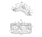
- FIG. 2 is a single product diagram illustrating an example of the first transmission body, where (a) is a front view of the first transmission body, and (b) is a cross-sectional view taken along the line bb of FIG. 2 (a).
- FIG. 3 is a single-piece view showing an example of the second transmission body, (c) is a front view of the second transmission body, and (d) is a sectional view taken along the line dd of FIG. 3 (c).
- FIG. 1 is an overall longitudinal sectional view showing a dog clutch according to an embodiment of the present invention.
- FIG. 2 is a single product diagram illustrating an example of the first transmission body, where (a) is a front view of the first transmission body, and (b) is a cross-sectional view taken along the line bb of FIG. 2 (a).
- FIG. 3 is a single-piece view showing an example of the second transmission body,
- FIG. 4 is a single-piece view showing an example of a relay member, where (e) is a front view of the relay member, and (f) is a cross-sectional view taken along line ff of FIG. 4 (e).
- FIG. 5 shows the disengaged state of the dog clutch, where (g) is a cross-sectional view taken along line 5 (g) -5 (g) in FIG. 1, and (h) is a cross-sectional view taken along line hh in FIG. It is line sectional drawing.
- FIG. 6 shows the state of the start of engagement of the dog clutch (that is, the initial engagement of the engagement dog with the high dog), where (i) is a diagram corresponding to FIG. 5 (g), and (j) is FIG. FIG.
- FIG. 6 is a cross-sectional view taken along line ij of i) (corresponding to FIG. 5H).
- FIG. 7 shows a state in the middle of engagement of the dog clutch (that is, the engagement dog has driven the high dog to the contact position with one of the low dogs), and (k) is a diagram corresponding to FIG. (L) is a cross-sectional view taken along the line l-l in FIG. 7 (k) (corresponding to FIG. 6 (j)).
- FIG. 8 shows a state in which the dog clutch is completely connected (that is, the engagement dog enters and engages in the gap between the high dog and the other low dog), and (m) is a diagram corresponding to FIG. Further, (n) is a cross-sectional view taken along the line nn of FIG. 8 (m) (corresponding to FIG. 7 (l)).
- a dog clutch D of the present invention is included as one of the power connection / disconnection means in a power transmission path between a power source E (for example, an in-vehicle engine) and a load W (for example, a wheel) in a vehicle, for example, an automobile.
- a transmission device for example, a constantly meshing transmission
- the dog clutch D includes a rotating shaft 3, a relay member 4 that is axially movable and relatively non-rotatably fitted to and supported by the outer peripheral surface of the rotating shaft 3 (spline fitting S ⁇ b> 1 in the embodiment), and the relay member 4.
- the first transmission member 1 that is disposed so as to face the side surface 4s on one side (left side in FIG. 1) in the axial direction and that is fitted and supported on the outer peripheral surface of the rotary shaft 3 so as to be relatively rotatable, and the relay member 4 described above.
- a second transmission body 2 that is arranged to face the side surface 4s and is rotatable relative to the first transmission body 1, and a twist as an elastic member interposed between the first and second transmission bodies 1 and 2.
- a spring 6 is provided.
- the rotating shaft 3 is connected to the power source E via a not-shown interlocking mechanism.
- the 1st transmission body 1 is connected to the load W via the output gearwheel 7 which rotates integrally with this, and the interlocking mechanism not shown.
- the output gear 7 is an example of an output member.
- a plurality of engagement dogs 4d protruding toward the first and second transmission bodies 1 and 2 are provided at regular intervals in the circumferential direction.
- An annular engagement groove 4g is formed in the outer peripheral surface of the relay member 4 on the back side of the engagement dogs 4d.
- An operation member 5 for example, a shift fork for driving the relay member 4 in the axial direction (that is, a forward / backward operation with respect to the first and second transmission bodies 1 and 2) engages with the engagement groove 4g.
- the first transmission body 1 includes a disc-shaped first transmission body main body 1m in which a rotation shaft 3 passes through a central portion of the first transmission body 1 and a first transmission body main body 1m that is connected to the opposite side of the relay member 4.
- An extending mounting boss 1b is integrally formed, and the inner peripheral surface of the mounting boss 1b is also fitted to the rotary shaft 3 so as to be rotatable.
- On the outer periphery of the first transmission body 1m there are a plurality of radially outwardly detachable low dogs 1d (the same number as the engagement dogs 4d in this embodiment) that can be engaged with and disengaged from the engagement dogs 4d. Projected at intervals.
- the outer peripheral surface of the mounting boss 1b has a small-diameter portion 1b1 on the distal end side, a medium-diameter portion 1b2 connected to the small-diameter portion 1b1 via the first step portion 1bs1, and a second step portion 1bs2 connected to the medium-diameter portion 1b2. And a stepped cylindrical surface having a large-diameter portion 1b3. Then, the inner peripheral portion of the output gear 7 is fitted to the small diameter portion 1b1 so as not to be relatively rotatable (in the embodiment, spline fitting S2), and the inner peripheral portion of the second transmission body 2 is rotatable to the middle diameter portion 1b2. Mated.
- a retaining ring 8 (for example, a circlip) that sandwiches the second transmission body 2 and the output gear 7 with the first transmission body 1m is provided at the front end of the small-diameter portion 1b1 of the mounting boss 1b.
- the retaining ring 8 is an example of retaining means, and instead of this, for example, a nut that is screwed to the tip of the mounting boss 1b (particularly, the small diameter portion 1b1) or a split pin that is locked to the tip.
- a crimped portion obtained by crimping the tip portion may be used as a retaining means.
- the outer periphery of the rotating shaft 3 is engaged with a restricting means (for example, a retaining ring 9 such as a circlip) that engages with the tip of the mounting boss 1b to restrict the movement of the first transmission body 1 in the axial direction.
- a restricting means for example, a retaining ring 9 such as a circlip
- the second transmission body 2 is disposed in an offset manner in the axial direction (particularly opposite to the relay member 4) with respect to the ring-shaped second transmission body 2m and the second transmission body 2m, and the second transmission body A ring-shaped small-diameter base portion 2b having a diameter smaller than 2 m and a plurality of connecting arm portions 2c arranged at equal intervals in the circumferential direction so as to integrally connect the second transmission body 2m and the small-diameter base portion 2b.
- the outer surface of each connecting arm portion 2c is formed as a slope inclined outward in the radial direction from the small diameter base portion 2b toward the second transmission body 2m.
- the inner peripheral surface of the small-diameter base portion 2b is rotatably fitted and supported on the middle-diameter portion 1b2 of the mounting boss portion 1b of the first transmission body 1.
- High dogs 2d are projected at equal intervals in the circumferential direction. Each of the high dogs 2d is disposed between the low dogs 1d and 1d adjacent in the circumferential direction, and protrudes closer to the relay member 4 than the low dog 1d in the axial direction.
- the torsion spring 6 is configured so that the high dog 2d and the low dog 1d are not engaged with the engaging dog 4d (for example, the dog clutch D is disengaged as shown in FIG. 5), and between the adjacent low dogs 1d and 1d.
- the high dog 2d is held by its own elasticity at a predetermined position (in this embodiment, an intermediate position between the low dogs 1d, that is, substantially in the middle).
- the high dog 2d is constituted by a torsion coil spring. Is done.
- the torsion spring 6 is disposed adjacent to the side surface 1 ms of the first transmission body 1 m opposite to the relay member 4, and both terminals 61 and 62 are connected to the first and second transmission bodies 1 and 2. It is latched by two mutually opposing side surfaces.
- the torsion spring 6 of the present embodiment has a coiled spring body portion 6m fitted into the large diameter portion 1b3 of the mounting boss portion 1b with a gap, and one end side of the spring body portion 6m.
- the first terminal portion 61 is locked in a first locking hole h1 that is recessed in the side surface 1ms of the first transmission body 1m.
- the second terminal portion 62 on the other end side of the spring main body portion 6m is recessed in the side surface 2bs of the second transmission body 2 (particularly the small diameter base portion 2b) facing the side surface 1ms of the first transmission body main body 1m. Locked in the locking hole h2.
- the small-diameter base portion 2b of the second transmission member 2 and the inner peripheral portion of the output gear 7 are fitted to the medium-diameter portion 1b2 and the small-diameter portion 1b1 of the mounting boss portion 1b of the first transmission member 1, respectively.
- a retaining ring 8 that sandwiches the small-diameter base portion 2b and the output gear 7 with the first transmission body 1m is attached to the tip of the small-diameter portion 1b1. Therefore, the 2nd transmission body 2 is supported by the attachment boss
- the spring body portion 6m of the torsion spring 6 is loosely fitted to the mounting boss portion 1b (large diameter portion 1b3) of the first transmission 1, and the first terminal portion of the spring 6 is engaged.
- the torsion spring 6 is temporarily fixed to the first transmission body 1 by locking 61 in the locking hole h1 of the first transmission body 1m.
- the small-diameter base portion 2b of the second transmission body 2 is fitted to the mounting boss portion 1b (medium-diameter portion 1b2) of the first transmission body 1, and the second terminal portion 62 of the torsion spring 6 is connected to the small-diameter base portion 2b.
- the second transmission body 2 and the torsion spring 6 are temporarily fixed to the first transmission body 1 by being locked in the locking holes h2.
- the output gear 7 is spline-fitted S2 to the mounting boss 1b (small-diameter portion 1b1), and then the retaining ring 8 is engaged with the small-diameter portion 1b1, so that between the retaining ring 8 and the first transmission body 1m.
- one subassembly is assembled by sandwiching the output gear 7, the second transmission body 2, and the torsion spring 6.
- the subassembly is fitted from one of the rotating shafts 3 (left side in FIG. 1), and the fitting state is held by a retaining ring 9 such as a circlip that is locked to the outer periphery of the rotating shaft 3.
- the relay member 4 is spline-fitted S1, and the operating member 5 is engaged with the engaging groove 4g on the outer periphery of the relay member 4, and this operating member 5
- the relay member 4 can be advanced and retracted at any time with respect to the first and second transmission members 1 and 2.
- the assembly procedure is not limited to the above.
- the dog clutch D assembled in this way and incorporated in a predetermined power transmission path is in the disconnected state (see FIG. 5), and the first transmission body 1 and the rotating shaft 3 are in relative rotation (for example, the rotating shaft 3). Is relayed to switch the dog clutch D to the connected state at a higher speed than the first transmission body 1 while rotating in the same direction as the first transmission body 1 or when the first transmission body 1 is stopped and only the rotating shaft 3 is rotating. A process of operating the member 4 to approach the first and second transmission bodies 1 and 2 is assumed.
- the high dog 2d having a protruding height higher than the low dog 1d is engaged with the engaging dog 4d in the rotational direction before the low dog 1d. Until the engagement, the engagement dog 4d and the low dog 1d can slide relative to each other in the rotational direction.
- the high dog 2d follows the engagement dog 4d rotating at a higher speed than this, and is elastically deforming the torsion spring 6 while surrounding the two low dogs 1d on both sides of the high dog 2d.
- it is finally engaged with one of the low dogs 1d (that is, the front side in the rotational direction of the rotating shaft 3).
- the other side ie, the rear side in the rotation direction
- the low dog 1d and the high dog 2d is relatively wide in the circumferential direction (ie, between the high dog 2d and the low dog 1d when the dog clutch D is disconnected).
- a gap 20 that is sufficiently wider than this gap 10 (in this embodiment, approximately twice as wide) is formed.
- the gap 20 is set to be substantially the same as or slightly wider than the circumferential width of the engagement dog 4d. Therefore, as shown in FIG. 8, the engagement dog 4d smoothly enters and engages in the gap 20, and the relay member 4 and the first transmission body 1 are connected so as not to be relatively rotatable. That is, the dog clutch D is switched to the connected state.
- the engagement dog 4d enters and engages with the wide gap 20 in the direction, the engagement dog 4d and the high dog 2d have a width of the low dog 1d as compared with the case where the engagement dog 4d engages with the high dog 2d alone. It is possible to reduce the backlash of the meshing portion, and an appropriate meshing state can be obtained.
- the dog clutch D is an extremely high performance dog clutch that can achieve both conflicting problems such as improvement of meshing efficiency and reduction of looseness of the meshing part while absorbing and mitigating impact during dog meshing.
- the high dog 2d and the low dog 1d are disengaged from the engaging dog 4d (that is, the clutch disengaged state), and the torsion spring 6 is adjacent to the low dog 1d,
- the high dog 2d is set to be held at a predetermined intermediate position between 1d (that is, substantially in the middle).
- the torsion spring 6 is disposed adjacent to the side surface 1 ms of the first transmission body 1 m opposite to the relay member 4, and both terminal portions 61, 62 are the first and second transmission bodies 1, 2. It is the installation mode latched by each. As a result, the torsion spring 6 can be arranged with a high degree of freedom without restricting the shapes of the relay member 4, the high dog 2d, and the low dog 1d, and is associated with the first and second transmission members 1 and 2, respectively. It can be stopped.
- the second transmission body 2 is supported by the first transmission body 1 so as to be slidable within a predetermined limited sliding range in the axial direction, and the first and second transmission bodies 1 are supported.
- 2 is provided with a torsion spring 6.
- the second transmission body 2 is rotatably fitted to the mounting boss 1b of the first transmission body 1 and the output gear 7 is fitted so as not to be relatively rotatable (spline fitting S2). Further, a retaining ring 8 is provided to sandwich the second transmission body 2 and the output gear 7 with the first transmission body 1m.
- a small assembly unit including the output gear 7 as well as the first and second transmission bodies 1 and 2 and the torsion spring 6, that is, a subassembly can be configured. Can be assembled to the rotary shaft 3 as a whole, so that the assembly workability is further improved.
- the common retaining means that is, the retaining ring 8 can be used to prevent the second transmission body 2 and the output gear 7 from coming off from the mounting boss 1b, the structure can be simplified accordingly.
- the rotary shaft 3 is the input side, that is, the side that is connected to the power source E (for example, an engine), and the first transmission body 1 is the output side, that is, the side that is connected to the load W (for example, a wheel).
- the dog clutch of the present invention may be arranged in the power transmission path with the first transmission body 1 as the input side and the rotating shaft 3 as the output side. In that case, instead of the output gear 7 (output member) of the first embodiment, an input gear (input member) interlocking with the load W is fitted to the mounting boss 1b of the first transmission body 1 so as not to be relatively rotatable. Fixed.
- the torsion spring 6 of the above embodiment has an intermediate position between the adjacent low dogs 1d and 1d (ie, substantially the middle) when the high dog 2d and the low dog 1d are not engaged with the engaging dog 4d.
- FIG. 2 shows the one that holds the high dog 2d, the position where the high dog 2d abuts against one of the adjacent low dogs 1d and 1d by the elastic force of the torsion spring 6, or the middle. You may make it hold
- the dog clutch D is applied to a transmission of an automobile.
- the application object of the dog clutch of the present invention is not limited to the embodiment. That is, the dog clutch of the present invention can be applied to various transmission mechanical devices, and the use thereof is not limited to vehicles and transmissions.
Landscapes
- Engineering & Computer Science (AREA)
- General Engineering & Computer Science (AREA)
- Mechanical Engineering (AREA)
- Mechanical Operated Clutches (AREA)
Abstract
L'invention concerne un embrayage à griffes (D), lequel embrayage comprend : un élément de relais (4) qui est supporté sur un arbre rotatif (3) de manière à être mobile dans la direction axiale et de manière à être incapable d'une rotation relative ; un premier corps de transmission (1) qui est apte à une rotation relative par rapport à l'arbre rotatif ; un second corps de transmission (2) qui est apte à tourner par rapport au premier corps de transmission ; et un élément élastique (6) qui peut maintenir une griffe haute (2d) du second corps de transmission dans une position prescrite entre des griffes basses adjacentes (1d, 1d) du premier corps de transmission. Dans un procédé dans lequel l'élément de relais est amené à s'approcher des premier et second corps de transmission pendant un état de rotation relative entre le premier corps de transmission et l'arbre rotatif, si une griffe haute, qui vient en prise avec une griffe de prise (4d) avant les griffes basses, vient en prise contre l'élément élastique sur l'une des griffes basses parmi les griffes basses adjacentes, un espace de direction périphérique (20) est formé entre l'autre griffe basse et la griffe haute, les griffes de prise pouvant pénétrer dans cet espace. Par cette configuration, il est procuré un embrayage à griffes qui peut accroître l'efficacité d'engrènement et réduire le jeu après l'engrènement tout en augmentant les effets d'absorption d'impact pendant l'engrènement d'une griffe.
Applications Claiming Priority (2)
| Application Number | Priority Date | Filing Date | Title |
|---|---|---|---|
| JP2018-036622 | 2018-03-01 | ||
| JP2018036622A JP2019152249A (ja) | 2018-03-01 | 2018-03-01 | ドグクラッチ |
Publications (1)
| Publication Number | Publication Date |
|---|---|
| WO2019167999A1 true WO2019167999A1 (fr) | 2019-09-06 |
Family
ID=67806262
Family Applications (1)
| Application Number | Title | Priority Date | Filing Date |
|---|---|---|---|
| PCT/JP2019/007468 WO2019167999A1 (fr) | 2018-03-01 | 2019-02-27 | Embrayage à griffes |
Country Status (2)
| Country | Link |
|---|---|
| JP (1) | JP2019152249A (fr) |
| WO (1) | WO2019167999A1 (fr) |
Citations (3)
| Publication number | Priority date | Publication date | Assignee | Title |
|---|---|---|---|---|
| JP2014152879A (ja) * | 2013-02-12 | 2014-08-25 | Fuji Heavy Ind Ltd | 動力伝達装置 |
| JP2015105697A (ja) * | 2013-11-29 | 2015-06-08 | 武蔵精密工業株式会社 | ドグクラッチ |
| US20150300417A1 (en) * | 2012-10-31 | 2015-10-22 | Daimler Ag | Form-Fitting Switching Unit for a Motor Vehicle Drive Train |
-
2018
- 2018-03-01 JP JP2018036622A patent/JP2019152249A/ja active Pending
-
2019
- 2019-02-27 WO PCT/JP2019/007468 patent/WO2019167999A1/fr active Application Filing
Patent Citations (3)
| Publication number | Priority date | Publication date | Assignee | Title |
|---|---|---|---|---|
| US20150300417A1 (en) * | 2012-10-31 | 2015-10-22 | Daimler Ag | Form-Fitting Switching Unit for a Motor Vehicle Drive Train |
| JP2014152879A (ja) * | 2013-02-12 | 2014-08-25 | Fuji Heavy Ind Ltd | 動力伝達装置 |
| JP2015105697A (ja) * | 2013-11-29 | 2015-06-08 | 武蔵精密工業株式会社 | ドグクラッチ |
Also Published As
| Publication number | Publication date |
|---|---|
| JP2019152249A (ja) | 2019-09-12 |
Similar Documents
| Publication | Publication Date | Title |
|---|---|---|
| CN108350952B (zh) | 动力传动系统快速断开装置 | |
| KR101945432B1 (ko) | 차량의 회전축의 지지 구조 | |
| US6378677B1 (en) | Power transmission device having electromagnetic clutch | |
| US9156351B2 (en) | Power transfer device with low effort mode shift system | |
| US10220702B2 (en) | Motive force transmission device and production method therefor | |
| US20150045171A1 (en) | Axle differential transmission for an engageably driven vehicle of a motor vehicle | |
| CN109642654B (zh) | 用于机动车辆的差速器 | |
| US9897186B2 (en) | Vehicular differential apparatus | |
| JP6277895B2 (ja) | トルク伝達部材及び駆動軸と被駆動軸との結合部 | |
| JP2007040424A (ja) | 電動リニアアクチュエータ | |
| WO2019167999A1 (fr) | Embrayage à griffes | |
| US10988022B2 (en) | Electro-mechanical on demand (EMOD) transfer case—dual drive gear and shift fork consolidation | |
| JP3226587U (ja) | 双安定型ラッチ機構及びそれを用いて作られた駆動系高速接続解除装置 | |
| JP6696295B2 (ja) | 動力伝達装置 | |
| JP2016088406A (ja) | 四輪駆動車の差動制限装置 | |
| EP3055587B1 (fr) | Transmission automatique | |
| JP2686187B2 (ja) | 動力伝達用緩衝ギヤ | |
| JP7476873B2 (ja) | 動力伝達装置 | |
| US11796043B1 (en) | Differential device | |
| EP3851705A1 (fr) | Differentiel pour une vehicule | |
| CN110962590A (zh) | 电驱动桥及车辆 | |
| JP5915375B2 (ja) | トルク伝達用継手及び電動式パワーステアリング装置 | |
| WO2022074958A1 (fr) | Transmission à deux vitesses | |
| JP4582055B2 (ja) | スタータ | |
| JP6187608B2 (ja) | トルク伝達用継手及び電動式パワーステアリング装置 |
Legal Events
| Date | Code | Title | Description |
|---|---|---|---|
| 121 | Ep: the epo has been informed by wipo that ep was designated in this application |
Ref document number: 19759984 Country of ref document: EP Kind code of ref document: A1 |
|
| NENP | Non-entry into the national phase |
Ref country code: DE |
|
| 122 | Ep: pct application non-entry in european phase |
Ref document number: 19759984 Country of ref document: EP Kind code of ref document: A1 |