WO2019167232A1 - 冷却装置および冷却水の処理方法 - Google Patents
冷却装置および冷却水の処理方法 Download PDFInfo
- Publication number
- WO2019167232A1 WO2019167232A1 PCT/JP2018/007811 JP2018007811W WO2019167232A1 WO 2019167232 A1 WO2019167232 A1 WO 2019167232A1 JP 2018007811 W JP2018007811 W JP 2018007811W WO 2019167232 A1 WO2019167232 A1 WO 2019167232A1
- Authority
- WO
- WIPO (PCT)
- Prior art keywords
- cooling water
- flow rate
- metal member
- conductivity
- main pipe
- Prior art date
- Legal status (The legal status is an assumption and is not a legal conclusion. Google has not performed a legal analysis and makes no representation as to the accuracy of the status listed.)
- Ceased
Links
Images


Classifications
-
- H—ELECTRICITY
- H05—ELECTRIC TECHNIQUES NOT OTHERWISE PROVIDED FOR
- H05K—PRINTED CIRCUITS; CASINGS OR CONSTRUCTIONAL DETAILS OF ELECTRIC APPARATUS; MANUFACTURE OF ASSEMBLAGES OF ELECTRICAL COMPONENTS
- H05K7/00—Constructional details common to different types of electric apparatus
- H05K7/20—Modifications to facilitate cooling, ventilating, or heating
Definitions
- Embodiments of the present invention relate to a cooling device and a cooling water treatment method.
- a cooling device that circulates cooling water between a metal member included in the electric device and a heat exchanger that cools the cooling water is known as one of cooling devices that cool the electric device.
- the cooling water used in such a cooling device for example, cooling water having a conductivity equal to or lower than a predetermined value (hereinafter referred to as “predetermined cooling water”) is used in order to prevent a short circuit in an electric device.
- the predetermined cooling water when the predetermined cooling water is obtained by lowering the conductivity of the cooling water such as tap water, it may take a certain time or more to lower the conductivity.
- the problem to be solved by the present invention is to provide a cooling device and a cooling water treatment method capable of efficiently reducing the conductivity of the cooling water.
- the cooling device is a cooling device that cools an electric device using cooling water, and includes a main pipe, a branch pipe, an ion removing unit, a flow rate adjusting unit, and a control unit.
- the main pipe circulates the cooling water between the inside of a metal member included in the electric device and a heat exchanger that cools the cooling water.
- the branch pipe branches from the main pipe and returns a part of the cooling water flowing through the main pipe to the main pipe without passing through the inside of the metal member.
- the ion removing unit is provided in the branch pipe.
- the flow rate adjusting unit is provided in the main pipe, the branch pipe, or another branch pipe branched from the main pipe, and can adjust the flow rate of the cooling water flowing into the metal member from the main pipe. is there.
- the control unit switches the setting of the flow rate adjustment unit so that the cooling water flows in the metal member at a rated flow rate or higher during steady operation, and the value related to the conductivity of the cooling water does not satisfy a predetermined condition.
- the setting of the flow rate adjustment unit is switched so that the cooling water has a flow rate that flows in the metal member at a second flow rate that is slower than the first flow rate that is the flow rate at the rated flow rate.
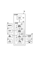
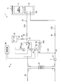
- FIG. 1 is a diagram illustrating an example of a drive system according to a first embodiment.
- the block diagram which shows the function structure of the control apparatus of 1st Embodiment.
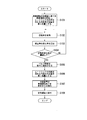
- the flowchart which shows an example of the flow of a process of 1st Embodiment.
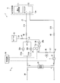
- FIG. 1 is a diagram illustrating an example of a drive system 1 (electric motor control system) including a cooling device 6.
- the drive system 1 includes, for example, a power conversion device 5 and a cooling device 6.
- the power conversion device 5 is an example of an “electric device”.
- the power conversion device 5 includes a power conversion circuit 11 and a heat sink 12.
- the power conversion circuit 11 includes, for example, a plurality of switching elements and diodes, and converts power between AC power and DC power.
- the power conversion circuit 11 supplies the converted power to a load (not shown) (for example, an electric motor).
- the power conversion circuit 11 generates heat each time the switching element is switched, for example.
- the power conversion circuit 11 is an example of a “heat generating component”.
- the heat sink 12 is attached with one or more modules constituting the power conversion circuit 11 and receives heat from the power conversion circuit 11. Inside the heat sink 12, a flow path 12a through which cooling water flows is provided.
- the heat sink 12 is made of metal and is an example of a “metal member”.
- the heat sink 12 is made of, for example, a metal having a higher ionization tendency than copper or an alloy of the metal.
- the heat sink 12 is formed of aluminum or an aluminum alloy.
- the material of the heat sink 12 is not limited to the above example.
- the drive system 1 described above is merely an example of a device or system in which the cooling device 6 is used.
- the cooling device 6 is not limited to the above example, and can be widely used in various devices and systems that require cooling.
- the cooling device 6 includes, for example, a main pipe 21, pumps 22A and 22B, a tank 23, a tank pipe 24, a heat exchanger 25, a heat exchanger cooling pipe 26, a branch pipe 27, an ion removal unit 28, and a first flow meter. 31, a second flow meter 32, a conductivity meter 33, a thermometer 34, a flow rate adjustment valve 35, and a control device 36.
- the main pipe 21 is provided so as to connect the heat sink 12 of the power converter 5 and the heat exchanger 25, and circulates cooling water between the inside of the heat sink 12 and the heat exchanger 25. More specifically, the main pipe 21 has a first pipe part 21A and a second pipe part 21B.
- the first piping portion 21 ⁇ / b> A extends between the heat sink 12 and the heat exchanger 25, and guides the cooling water heated by passing through the heat sink 12 to the heat exchanger 25.
- the first piping portion 21A includes, for example, a first portion 21Aa and a second portion 21Ab that branch into two in the middle of the first piping portion 21A and merge again. However, 21 A of 1st piping parts do not need to have such a branch part.
- the second piping portion 21B extends between the heat exchanger 25 and the heat sink 12 at a position different from the first piping portion 21A, and the cooling water cooled by passing through the heat exchanger 25 is transferred to the heat sink 12.
- the main pipe 21 and a branch pipe 27 described later are made of stainless steel, for example.
- the two pumps 22A and 22B are provided in the first piping portion 21A.
- one pump 22A is provided in the first portion 21Aa of the first piping portion 21A.
- the other pump 22B is provided in the second portion 21Ab of the first piping portion 21A.
- the two pumps 22A and 22B are provided for redundancy, for example. For this reason, either one of the two pumps 22A and 22B may be omitted.
- the tank 23 is connected to the first piping portion 21 ⁇ / b> A via the tank piping 24.
- a portion where the first piping portion 21A and the tank piping 24 are connected is referred to as a “connecting portion c1”.
- the tank 23 is supplied with cooling water (for example, tap water) before the electrical conductivity is lowered to a predetermined value or less.
- a valve 41 is provided in the middle of the tank pipe 24. By opening the valve 41, the cooling water in the tank 23 is supplied to the first piping portion 21A.
- the main pipe 21 is provided with two valves 42 and 43.
- One valve 42 is provided between the connection part c1 and the heat sink 12 in the first piping part 21A. From another viewpoint, the valve 42 is provided between the heat sink 12 and the portion of the first piping portion 21A where the branch piping 27 merges with the first piping portion 21A (a merging portion c3 described later). Yes.
- the other valve 43 is provided between the heat sink 12 and a portion of the second piping portion 21B where the branch piping 27 branches from the second piping portion 21B (a branching portion c2 described later). By opening the valves 42 and 43, the cooling water can circulate through the main pipe 21.
- the heat exchanger 25 cools the cooling water flowing from the heat sink 12 through the main pipe 21 into the heat exchanger 25.
- a heat exchanger cooling pipe 26 is connected to the heat exchanger 25.
- the heat exchanger 25 cools the cooling water circulating in the main pipe 21 by supplying secondary cooling water from the outside through the heat exchanger cooling pipe 26.
- the heat exchanger 25 may cool the cooling water circulating through the main pipe 21 by forced air cooling with a fan.
- the branch pipe 27 branches off from the middle of the second pipe portion 21B.
- a portion where the branch piping 27 branches from the second piping portion 21B is referred to as a “branching portion c2.”
- the branch pipe 27 joins in the middle of the first pipe portion 21A.
- 21 A of 1st piping parts the part where branch piping 27 merged with 21 A of 1st piping parts is called "merging part c3.”
- an ion removing unit 28 described later is provided in the middle of the branch pipe 27, an ion removing unit 28 described later is provided.
- the branch pipe 27 passes a part of the cooling water flowing through the second pipe part 21B through the ion removing part 28 and returns it to the first pipe part 21A without passing through the inside of the heat sink 12.
- the ion removing unit 28 removes at least a part of the ions contained in the cooling water flowing through the branch pipe 27.
- the ion removing unit 28 includes an ion exchange resin 28a.
- the ion exchange resin 28a takes in ions contained in the cooling water (for example, metal ions dissolved from the metal material forming the heat sink 12), and discharges ions (H + and OH ⁇ ) held by the ion exchange resin 28a instead.
- H + and OH ⁇ released from the ion exchange resin 28a react with each other to form water. Thereby, the ions contained in the cooling water are removed.
- the ion removing unit 28 reduces the conductivity of the cooling water by removing ions contained in the cooling water.
- the cooling water whose conductivity has been reduced by passing through the ion removing section 28 is returned to the first piping section 21 ⁇ / b> A and merges with the cooling water that has passed through the heat sink 12.
- the cooling device 6 guides a part of the cooling water flowing through the main pipe 21 to the ion removing unit 28 via the branch pipe 27 by adjusting the opening degree of a flow rate adjusting valve 35 described later during the steady operation. . Thereby, ions contained in the cooling water are removed, and the conductivity of the cooling water is kept below the threshold value.
- the 1st flow meter 31 is provided in the 2nd piping part 21B.
- the first flow meter 31 is provided between the branch part c2 and the heat exchanger 25 in the second piping part 21B.
- the first flow meter 31 measures the flow rate of the cooling water flowing through the second piping part 21B on the upstream side of the branch part c2.
- the 1st flow meter 31 measures the total flow volume of the cooling water which flows into the inside of the heat sink 12 from the 2nd piping part 21B, and the cooling water which flows into the branch piping 27 from the 2nd piping part 21B.
- the first flow meter 31 may be provided between the branch part c2 and the heat sink 12 in the second piping part 21B.
- the second piping part 21B measures the flow rate of the cooling water that flows into the heat sink 12 from the second piping part 21B without flowing into the branch pipe 27 in the cooling water flowing through the second piping part 21B.
- the 1st flow meter 31 may be provided in 21 A of 1st piping parts instead of the 2nd piping part 21B. The measurement result of the first flow meter 31 is output to the control device 36.
- the second flow meter 32 is provided in the branch pipe 27.
- the second flow meter 32 measures the flow rate of the cooling water flowing through the branch pipe 27.
- the 2nd flow meter 32 may be provided between the branch part c2 and the ion removal part 28 in the branch piping 27, and may be provided between the ion removal part 28 and the junction part c3.
- the measurement result of the second flow meter 32 is output to the control device 36.
- the conductivity meter 33 is provided in the branch pipe 27, for example, and measures the conductivity of the cooling water flowing through the branch pipe 27.
- the conductivity meter 33 is provided between the branch part c ⁇ b> 2 and the ion removing unit 28 in the branch pipe 27, and measures the conductivity of the cooling water before flowing into the ion removing unit 28.
- the conductivity meter 33 may be provided in the main pipe 21 instead of the branch pipe 27.
- the measurement result of the conductivity meter 33 is output to the control device 36.
- “conductivity of cooling water” is an example of “value related to conductivity of cooling water”.
- the “value relating to the conductivity of the cooling water” is not limited to the conductivity, but may be, for example, the electrical resistivity of the cooling water, the conductivity or the rate of change of the electrical resistivity per unit time, It may be the amount of change in resistivity per unit time.
- the cooling device 6 may be provided with a measurement unit that measures the electrical resistivity of the cooling water instead of the conductivity meter 33.
- thermometer 34 is disposed near the conductivity meter 33, and the conductivity meter 33 measures the temperature of the cooling water at which the conductivity is measured.
- the thermometer 34 may be provided inside the conductivity meter 33.
- the measurement result of the thermometer 34 is output to the control device 36.
- the temperature measured by the thermometer 34 is used for temperature correction of the conductivity measured by the conductivity meter 33.
- the flow rate adjustment valve 35 is provided in the main pipe 21, for example.
- the flow rate adjustment valve 35 is provided between the merging portion c3 and the heat sink 12 in the first piping portion 21A.
- the installation position of the flow rate adjustment valve 35 is not limited to the above example.
- the flow rate adjusting valve 35 may be provided between the branch portion c2 and the heat sink 12 in the second piping portion 21B, or may be provided in the branch piping 27.
- An example in which the flow rate adjusting valve 35 is provided in the branch pipe 27 will be described later in detail as the second embodiment.
- the flow rate adjustment valve 35 is, for example, an electromagnetic valve.
- the flow rate adjusting valve 35 includes a valve body provided inside the flow rate adjusting valve 35 and an actuator (for example, a motor or a solenoid) that changes the position or angle of the valve body.
- the flow rate adjusting valve 35 operates an actuator based on a control command from the control device 36 to change the position or angle of the valve body.
- the flow rate adjustment valve 35 can change the opening degree of the flow rate adjustment valve 35 by changing the position or angle of the valve body.
- the flow rate adjustment valve 35 can adjust the flow rate of the cooling water flowing into the heat sink 12 from the main pipe 21 by changing the opening degree of the flow rate adjustment valve 35.
- the flow rate adjustment valve 35 reduces the flow rate of the cooling water flowing into the heat sink 12 from the main pipe 21 by reducing the opening degree of the flow rate adjustment valve 35. In this case, the flow rate of the cooling water flowing into the branch pipe 27 from the second pipe portion 21B increases.
- the flow rate adjustment valve 35 increases the flow rate of the cooling water flowing into the heat sink 12 from the main pipe 21 by increasing the opening degree of the flow rate adjustment valve 35. In this case, the flow rate of the cooling water flowing into the branch pipe 27 from the second pipe portion 21B decreases.
- the cross-sectional area (cross-sectional area along the direction orthogonal to the flow direction) of the flow path 12a inside the heat sink 12 is always constant regardless of time.
- the flow rate adjustment valve 35 is an example of a “flow rate adjustment unit”.
- the control device 36 controls the cooling device 6 based on the measurement results of the first flow meter 31, the second flow meter 32, the conductivity meter 33, and the thermometer 34.
- the control device 36 performs a predetermined operation for efficiently reducing the conductivity of the cooling water by controlling the flow rate adjustment valve 35 based on at least the measurement results of the conductivity meter 33 and the thermometer 34. This is realized in the cooling device 6.
- this content will be described in detail.
- FIG. 2 is a block diagram showing a functional configuration of the control device 36.
- the control device 36 includes a control unit 51 and a storage unit 52.
- the control unit 51 includes, for example, a conductivity correction unit 511, a conductivity determination unit 512, a flow rate control unit 513, and an information output unit 514.
- At least a part of the conductivity correction unit 511, the conductivity determination unit 512, the flow rate control unit 513, and the information output unit 514 is stored in the storage unit 52 as a hardware processor such as a CPU (Central Processing Unit). This is realized by executing a computer program (software). Some or all of these functional units are hardware (including a circuit unit; circuit) such as LSI (Large Scale Integration), ASIC (Application Specific Integrated Circuit), or FPGA (Field-Programmable Gate Array). It may be realized by cooperation of software and hardware.
- LSI Large Scale Integration
- ASIC Application Specific Integrated Circuit
- FPGA Field-Programmable Gate Array
- the storage unit 52 is realized by, for example, a RAM (Random Access Memory), a ROM (Read Only Memory), an HDD (Hard Disk Drive), a flash memory, or a hybrid storage device in which a plurality of these are combined.
- a RAM Random Access Memory
- ROM Read Only Memory
- HDD Hard Disk Drive
- flash memory or a hybrid storage device in which a plurality of these are combined.
- calculation formulas and coefficients relating to the temperature correction of the conductivity, various threshold values, a target flow rate value of the cooling water flowing in the heat sink 12 during the steady operation and the preparation operation of the cooling device 6 (or Information indicating the target opening degree of the flow rate adjusting valve 35 and the like is stored.
- the conductivity correction unit 511 receives the measurement result of the conductivity meter 33 from the conductivity meter 33.
- the conductivity correction unit 511 receives the measurement result of the thermometer 34 from the thermometer 34.
- the conductivity varies with temperature. Therefore, the conductivity correction unit 511 performs temperature correction of the conductivity detected by the conductivity meter 33 based on the temperature of the cooling water measured by the thermometer 34.
- the conductivity correction unit 511 performs the temperature correction of the conductivity based on a temperature correction formula such as the following formula (1).
- the conductivity correction unit 511 outputs the conductivity value corrected by the temperature correction to the conductivity determination unit 512.
- K 25 K t / [1 + ⁇ (t ⁇ 25)] (1)
- K 25 is the conductivity at 25 ° C.
- K t is the conductivity at t ° C.
- ⁇ is the temperature coefficient (for example, 2.0% / ° C.).
- the conductivity determination unit 512 determines whether or not the conductivity satisfies a predetermined condition based on the conductivity whose temperature has been corrected by the conductivity correction unit 511 (hereinafter sometimes simply referred to as “conductivity”). .
- the “predetermined condition” refers to, for example, the conductivity of the cooling water is low enough to allow the cooling water to flow through the heat sink 12 during the steady operation of the cooling device 6 (during steady operation of the power conversion device 5). This is a condition to show.
- the conductivity determination unit 512 calculates a rate of change per unit time for the conductivity measured by the conductivity meter 33 and subjected to temperature correction.
- the conductivity determination unit 512 compares the change rate of the conductivity per unit time with the threshold value stored in advance in the storage unit 52, and the change rate of the conductivity per unit time is equal to or less than the threshold value (for example, 1%). In the case of the following), it is determined that the value related to the electrical conductivity satisfies a predetermined condition.
- the conductivity determination unit 512 outputs a determination result regarding conductivity to the flow rate control unit 513 and the information output unit 514.
- the value relating to the electrical conductivity satisfies a predetermined condition is not limited to the rate of change of the electrical conductivity per unit time falling below a threshold value. “The value related to the electrical conductivity satisfies a predetermined condition” means that the electrical conductivity of the cooling water falls below the threshold, the electrical resistivity of the cooling water rises above the threshold, and the unit of electrical resistivity of the cooling water It may be that the rate of change per hour falls below a threshold, or the amount of change per unit time in the conductivity or electrical resistivity of cooling water falls below a threshold.
- the flow rate control unit 513 controls the flow rate adjustment valve 35 based on the determination result of the conductivity determination unit 512. For example, the flow rate control unit 513 switches the setting of the flow rate adjustment valve 35 so that the cooling water flows in the heat sink 12 at a rated flow rate (first flow rate) or more during the steady operation of the cooling device 6. “Setting so that the cooling water flows at a rated flow rate or higher” includes a case where the cooling water is set to flow at a rated flow rate.
- the flow rate control unit 513 is slower than the first flow rate that is the flow rate at the rated flow rate inside the heat sink 12. The setting of the flow rate adjustment valve 35 is switched so that the flow rate (second flow rate) flows at two flow rates.
- flow velocity means the flow velocity on the inner surface (contact surface with cooling water) of the flow path 12a of the heat sink 12.
- control of the flow rate of the cooling water can be performed by controlling the flow rate of the cooling water (for example, switching the setting of the flow rate).
- changing the flow rate of the cooling water as a result of controlling the flow rate of the cooling water may be referred to as “controlling the flow rate of the cooling water”.
- the “first flow rate” is the flow rate of the cooling water on the inner surface (contact surface with the cooling water) of the flow path 12a of the heat sink 12 when the cooling water is supplied to the power converter 5 at the rated flow rate (first flow rate). is there.
- the “rated flow rate (first flow rate)” is a flow rate set with a predetermined margin with respect to the flow rate of cooling water required for cooling the power conversion device 5 when the power conversion device 5 performs rated operation.
- the “second flow velocity” is the inner surface of the flow path 12a of the heat sink 12 (contact surface with the cooling water) when the flow rate of the cooling water flowing through the power conversion device 5 is a second flow rate lower than the first flow rate.
- the flow rate control unit 513 reduces the flow rate of the cooling water flowing from the main pipe 21 into the heat sink 12 by reducing the opening of the flow rate adjustment valve 35 as compared with that during the steady operation, The flow rate of the cooling water flowing inside the heat sink 12 is set to the second flow rate.
- the flow rate control unit 513 reduces the opening degree of the flow rate adjustment valve 35 as compared with that in the steady operation, so that the cooling water flows from the main pipe 21 into the branch pipe 27 and passes through the ion removal unit 28. Increase the rate compared to steady operation.
- the flow rate control unit 513 reduces the flow rate of the cooling water flowing into the heat sink 12 from the main pipe 21 as compared with that in the steady operation, and sets the flow rate of the cooling water flowing inside the heat sink 12 to the second flow rate. .
- a passive film in the heat sink 12 and fluid corrosion due to cooling water will be described.
- metal ions contained in the cooling water react with oxygen, and a passive film (oxide film) such as Al 2 O 3 is formed on the inner surface of the flow path 12 a in the heat sink 12.
- a passive film oxide film
- the passive film becomes stable, and metal ions are less likely to dissolve into the cooling water from the metal material forming the heat sink 12.
- the ion concentration of the cooling water is difficult to increase.
- the speed of the cooling water flowing inside the heat sink 12 is large, the rate of progress of fluid corrosion by the cooling water increases, and the passive film flows through the cooling water before the passive film grows to the predetermined thickness. An event that occurs due to corrosion occurs. As a result, the metal ions that form the heat sink 12 may continue to melt into the cooling water.
- the second flow rate is a flow rate at which the speed at which the passive film grows on the inner surface of the flow path 12a in the heat sink 12 is greater than the speed at which the passive film is scraped by the flow corrosion of cooling water.
- a flow velocity is obtained in advance according to the material of the heat sink 12, the usage environment of the cooling device 6, and the like by a preliminary test. Note that the relationship between the flow velocity and the flow rate can be obtained in advance by a preliminary test.
- the flow control unit 513 receives the measurement result of the first flow meter 31 from the first flow meter 31.
- the flow controller 513 receives the measurement result of the second flow meter 32 from the second flow meter 32.
- the flow control unit 513 calculates the flow rate of the cooling water flowing into the heat sink 12 from the main pipe 21 by subtracting the measurement result of the second flow meter 32 from the measurement result of the first flow meter 31, for example.
- the flow rate controller 513 controls the flow rate adjustment valve 35 based on the flow rate calculated from the measurement results of the first and second flow meters 31 and 32. For example, the flow rate control unit 513 controls the flow rate adjustment valve 35 so that the flow rate of the cooling water flowing into the heat sink 12 from the main pipe 21 approaches the first target flow rate value set in advance.
- the flow rate of the cooling water flowing inside is controlled to the first flow rate.
- the flow rate control unit 513 controls the flow rate adjustment valve 35 so that the flow rate of the cooling water flowing into the heat sink 12 from the main pipe 21 approaches the preset second target flow rate value.
- the flow rate of the cooling water flowing inside is controlled to the second flow rate.
- the flow rate control unit 513 controls the flow rate adjustment valve 35 so as to bring the opening degree of the flow rate adjustment valve 35 close to the first target opening degree set in advance, thereby flowing inside the heat sink 12.
- the flow rate of the cooling water may be controlled to the first flow rate.
- the flow rate control unit 513 controls the flow rate adjustment valve 35 so that the opening degree of the flow rate adjustment valve 35 approaches the preset second target opening degree, so that the cooling water flowing inside the heat sink 12 is controlled.
- the flow rate may be controlled to the second flow rate.
- the flow rate control unit 513 outputs information related to control of the flow rate adjustment valve 35 (for example, information indicating the opening degree of the flow rate adjustment valve 35) to the information output unit 514.
- the information output unit 514 generates predetermined information or a signal based on at least one of the determination result regarding the conductivity received from the conductivity determination unit 512 and the information regarding the control of the flow rate adjustment valve 35 received from the flow rate control unit 513.
- the generated information or signal is output to the outside of the cooling device 6.
- the information or signal output from the information output unit 514 is information or a signal for displaying or notifying a predetermined state of the cooling device 6 on a user interface device U (for example, a display device) that is an external device. .
- the “predetermined state” is, for example, that the value related to the conductivity of the cooling water satisfies a predetermined condition (that the operation at the second flow rate may be terminated), or the rated flow rate (first flow rate).
- the switching of the flow rate of the cooling water to is completed.
- FIG. 3 is a flowchart showing an example of a process flow for obtaining cooling water having a conductivity equal to or lower than a threshold value from tap water. Such processing is performed, for example, when newly installing the power conversion device 5 or during regular maintenance.
- the cooling device 6 is assembled, and the main pipe 21 is connected to the heat sink 12.
- the tap water is filled in the inside of the cooling device 6 and the flow path 12a of the heat sink 12 through the tank 23, for example. At this stage, the conductivity of tap water is higher than the threshold value.
- the controller 51 performs a preparatory operation for reducing the conductivity of tap water prior to the steady operation of the cooling device 6.
- the control unit 51 switches the setting of the flow rate adjustment valve 35 based on the second target flow rate value (or the second target opening) set in advance as the initial value of the preparatory operation.
- the control part 51 starts a preparatory operation, and controls the flow volume of the cooling water which flows through the inside of the heat sink 12 to the 2nd flow volume smaller than the time of a steady operation (S101).
- the flow rate of the cooling water flowing inside the heat sink 12 becomes the second flow rate.
- a part of the cooling water flowing through the main pipe 21 flows into the branch pipe 27 from the second pipe portion 21B.
- ions are exchanged by the ion removing unit 28, and the conductivity is lowered.
- the electrical conductivity of the cooling water circulating through the main pipe 21 gradually decreases.
- the control unit 51 acquires the conductivity from the measurement result of the conductivity meter 33 every unit time, and performs temperature correction based on the detection result of the thermometer 34 for the acquired conductivity (S102).
- the “unit time” is, for example, 10 minutes, but may be several seconds or several minutes.
- the control unit 51 calculates the rate of change of the conductivity per unit time based on the conductivity after temperature correction obtained at the previous sampling and the conductivity after temperature correction obtained at the current sampling. Is calculated (S103).
- control unit 51 compares the change rate of the conductivity per unit time with a preset threshold value, and determines whether or not the change rate of the conductivity per unit time is equal to or less than the threshold value ( S104).
- the control unit 51 returns to before S102 and repeats the processes of S102 to S104 every unit time.
- control unit 51 controls the flow rate adjustment valve 35 so that the opening degree of the flow rate adjustment valve 35 is gradually increased when the rate of change of conductivity per unit time is equal to or less than the threshold (S105). Thereby, the control unit 51 gradually increases the flow rate of the cooling water flowing from the main pipe 21 into the heat sink 12.
- the control unit 51 switches the setting of the flow rate adjustment valve 35 based on the first target flow rate value (or the first target opening degree) set in advance as the target flow rate value for steady operation, so that the inside of the heat sink 12 is changed.
- the flow rate of the flowing cooling water is set to the first flow rate (or a flow rate larger than the first flow rate) (S106).
- control unit 51 gradually increases the opening degree of the flow rate adjustment valve 35 until the flow rate of the cooling water flowing inside the heat sink 12 becomes the first flow rate that is the flow rate during steady operation. As a result, the flow rate of the cooling water flowing inside the heat sink 12 becomes the first flow rate.
- the control unit 51 causes the external device 6 to display or notify information indicating that the preparation operation of the cooling device 6 has been completed (S107). ). Then, the control unit 51 shifts the cooling device 6 from the preparation operation to the steady operation (S108). Thereafter, the control unit 51 continues the steady operation in a state where the cooling water flows in the heat sink 12 at the first flow rate (or faster than the first flow rate).
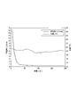
- FIG. 4 shows an example of an experimental result using the cooling device 6 described in the present embodiment.
- FIG. 4 shows an experimental example in which the conductivity of the tap water is lowered by supplying the tap water to the cooling device 6 and preliminarily operating the cooling device 6.
- the heat sink 12 used in this experimental example is made of an aluminum alloy.
- the conductivity of the cooling water decreases from the start of the preparation operation, and the conductivity becomes a low value close to the target value without waiting for one hour. Then, in about 2 to 3 hours from the start of the preparatory operation, the rate of change of the conductivity per unit time becomes equal to or less than a preset threshold value, and the state can be shifted to the steady operation.
- the conductivity of the cooling water can be efficiently reduced.
- a device including a cooling device is newly installed or when cooling water is extracted from the cooling device in a periodic inspection or the like, it is necessary to newly procure cooling water having a conductivity equal to or lower than a predetermined value.
- tap water that can be procured relatively easily is supplied to the cooling device, and the cooling device is operated, so that the conductivity of the cooling water is gradually lowered by the action of the ion removing unit provided in the cooling device.
- Work to be done. By such work, necessary cooling water can be prepared. However, such work may require a long time (for example, a full day). While this operation is being performed, it becomes difficult to use the electrical device.
- the cooling device 6 of the present embodiment controls the flow rate adjustment valve 35 so that the cooling water flows through the heat sink 12 at the first flow rate during the steady operation, and the value regarding the conductivity of the cooling water is a predetermined value.
- the control unit 51 controls the flow rate adjusting valve 35 so that the cooling water flows through the heat sink 12 at a second flow rate slower than the first flow rate.
- the metal ions are dissolved in the cooling water by the flow corrosion of the cooling water by suppressing the flow velocity of the cooling water flowing inside the heat sink 12 as compared with that in the steady operation.
- the ions contained in the cooling water can be removed by the ion removing unit 28 in a state where the release is suppressed. Thereby, the ion removal part 28 can be functioned more effectively, and the electrical conductivity of cooling water can be reduced efficiently.
- the second flow rate is such that when the cooling water flows inside the heat sink 12, the speed at which the passive film grows on the inner surface of the flow path 12 a of the heat sink 12 is the passive state due to the flow corrosion of the cooling water. It is a flow rate that is greater than the rate at which the coating is scraped. According to such a configuration, the progress of fluid corrosion of the cooling water can be suppressed, and the passive film can be grown to a predetermined thickness on the inner surface of the flow path 12a of the heat sink 12. When the passive film grows to a predetermined thickness on the inner surface of the flow path of the heat sink 12, the amount of ions dissolved into the cooling water from the metal material forming the heat sink 12 can be greatly reduced. Thereby, the ion removal part 28 can be functioned more effectively, and the electrical conductivity of cooling water can be reduced further efficiently.
- the control unit 51 controls the flow rate adjustment valve unit 35 so that the cooling water flows through the heat sink 12 at the second flow rate in the preparation operation prior to the steady operation. After that, the control unit 51 gradually increases the flow rate of the cooling water flowing into the heat sink 12 from the main pipe 21 when the value related to the conductivity of the cooling water satisfies the predetermined condition.
- the flow rate adjustment valve 35 is controlled so as to flow through the heat sink 12 at the first flow rate. According to such a configuration, even when a device including the cooling device 6 is newly installed or when the cooling water is removed from the cooling device 6 in a periodic inspection or the like, the conductivity is predetermined from tap water in a short time. Conductivity below the value can be obtained. Thereby, the work burden of the new installation of the apparatus containing the cooling device 6 and an inspection work can be reduced.
- the control unit 51 determines that the conductivity of the cooling water or the rate of change of the electrical resistivity is when the electrical conductivity of the cooling water is reduced to a threshold value or lower, or the electrical resistivity of the cooling water is increased to a threshold value or higher. It is determined that the predetermined condition is satisfied when the threshold value falls below the threshold value or when the amount of change in the conductivity or electrical resistivity of the cooling water falls below the threshold value. According to such a structure, the value regarding electrical conductivity can be easily monitored by the control part 51, and the determination which transfers the cooling device 6 from the said preparation operation to a normal operation can be performed automatically.
- the flow rate control unit 513 increases the proportion of cooling water that flows from the main pipe 21 into the branch pipe 27 and passes through the ion removal unit 28 as compared to during steady operation, thereby cooling the heat flow through the heat sink 12.
- the water flow rate is set to the second flow rate. According to such a configuration, the flow rate of the cooling water flowing inside the heat sink 12 is made slower than that in the steady operation to suppress the dissolution of ions, and more cooling water is supplied from the main pipe 21 to the ion removing unit 28. By guiding, the amount of ions removed by the ion removing unit 28 can be increased. Thereby, the ion removal part 28 can be functioned more effectively, and the electrical conductivity of cooling water can be reduced further efficiently.
- the heat sink 12 when the heat sink 12 is formed of a metal having a higher ionization tendency than copper or an alloy of the metal, the rate of dissolution of ions with respect to the cooling water is high, and tap water is supplied to the cooling device during steady operation. Even if it is circulated in the cooling device at a flow rate of 2 mm, the conductivity of the cooling water may not easily decrease. However, by setting the flow rate at which the cooling water flows through the heat sink 12 as the second flow rate, which is lower than that during steady operation, as in the present embodiment, the heat sink 12 has a higher ionization tendency than copper or an alloy of the metal. Even if it is formed by, the electrical conductivity of cooling water can be reduced.
- FIG. 5 is a diagram illustrating an example of the drive system 1 including the cooling device 6 of the present embodiment.
- the flow rate adjustment valve 35 is provided in the branch pipe 27.
- the flow rate adjusting valve 35 is provided between the branch part c ⁇ b> 2 and the ion removing part 28 in the branch pipe 27.
- the flow rate adjusting valve 35 adjusts the flow rate of the cooling water flowing from the main pipe 21 to the branch pipe 27 by changing the opening degree. As a result, the flow rate of the cooling water flowing from the main pipe 21 to the heat sink 12 is adjusted. Can be adjusted.
- the control device 36 controls the flow rate adjustment valve 35 based on the determination result of the conductivity determination unit 512. For example, the control device 36 increases the flow rate of the cooling water flowing from the main pipe 21 into the branch pipe 27 by increasing the opening degree of the flow rate adjustment valve 35 as compared with that in the steady operation. The flow rate of the cooling water flowing into the heat sink 12 is reduced. When the value related to the conductivity of the cooling water satisfies a predetermined condition, the control device 36 gradually decreases the opening degree of the flow rate adjusting valve 35 to thereby reduce the cooling water flowing into the branch pipe 27 from the main pipe 21. The flow rate is gradually decreased, and as a result, the flow rate of the cooling water flowing from the main pipe 21 into the heat sink 12 is gradually increased.
- FIG. 6 is a diagram illustrating an example of the drive system 1 including the cooling device 6 of the present embodiment.
- Each of the pumps 22A and 22B includes, for example, a driving body (for example, a rotating body or a reciprocating body) that pushes out cooling water.
- the control device 36 sends a control command to an inverter (for example, a VVVF (VariableBVariable Frequency) inverter) that supplies driving power to the pumps 22A and 22B, thereby driving the driving amount (for example, rotation) of the pumps 22A and 22B.
- the rotational speed of the body, or the moving amount or moving speed of the reciprocating body can be changed.
- the control apparatus 36 can change the flow velocity of the cooling water flowing through the main pipe 21.
- Each of the pumps 22A and 22B is an example of a “flow rate adjusting unit”.
- the control device 36 controls the pumps 22A and 22B based on the determination result of the conductivity determination unit 512. For example, the control device 36 reduces the flow rate of the cooling water flowing into the heat sink 12 from the main pipe 21 by reducing the drive amount of the drive bodies of the pumps 22A and 22B as compared with that in the steady operation. When the value related to the conductivity of the cooling water satisfies a predetermined condition, the control device 36 gradually increases the driving amount of the driving body of the pumps 22A and 22B to flow into the heat sink 12 from the main pipe 21. Gradually increase the flow rate of cooling water.
- FIG. 7 is a diagram illustrating an example of the drive system 1 including the cooling device 6 of the present embodiment.
- the cooling device 6 includes a bypass pipe 61 and a flow rate adjustment valve 35 provided in the bypass pipe 61.
- the bypass pipe 61 is branched from the main pipe 21.
- the bypass pipe 61 branches from the second pipe part 21B at a position between the branch part c2 and the heat sink 12 in the second pipe part 21B.
- the bypass pipe 61 joins the first pipe part 21A at a position between the joining part c3 and the heat sink 12 in the first pipe part 21A.
- the bypass pipe 61 returns a part of the cooling water passing through the second pipe part 21 ⁇ / b> B to the first pipe part 21 ⁇ / b> A without passing through the inside of the heat sink 12.
- the position of the bypass pipe 61 is not limited to the above example.
- the bypass pipe 61 is not provided with the ion removing unit 28.
- the bypass pipe 61 is an example of “another branch pipe”.
- the flow rate adjusting valve 35 adjusts the flow rate of the cooling water flowing into the bypass piping 61 from the main piping 21 by changing the opening degree. As a result, the cooling water flowing into the heat sink 12 from the main piping 21. The flow rate can be adjusted.
- the control device 36 controls the flow rate adjustment valve 35 based on the determination result of the conductivity determination unit 512. For example, the control device 36 increases the flow rate of the cooling water flowing from the main pipe 21 into the bypass pipe 61 by increasing the opening degree of the flow rate adjustment valve 35 as compared with that in the steady operation. The flow rate of the cooling water flowing into the heat sink 12 is reduced. When the value related to the conductivity of the cooling water satisfies a predetermined condition, the control device 36 gradually decreases the opening degree of the flow rate adjustment valve 35 so that the cooling water flowing into the bypass pipe 61 from the main pipe 21. The flow rate is gradually decreased, and as a result, the flow rate of the cooling water flowing from the main pipe 21 into the heat sink 12 is gradually increased.
- the embodiments are not limited to the above examples.
- the example in which the flow rate adjusting valve 35 and the pumps 22A and 22B adjust the flow rate according to the control command from the control device 36 has been described.
- the flow rate adjustment by the flow rate adjustment valve 35 and the pumps 22A and 22B may be performed manually.
- the flow rate of the cooling water flowing into the heat sink 12 from the main pipe 21 is adjusted by the operator manually opening the valve, or by the operator performing an input operation on the valve control device or the pump control device. May be.
- the cooling water flows through the metal member at a rated flow rate or higher during steady operation, and the value regarding the conductivity of the cooling water does not satisfy a predetermined condition,
- the conductivity of the cooling water can be efficiently reduced. it can.
Landscapes
- Physics & Mathematics (AREA)
- Thermal Sciences (AREA)
- Engineering & Computer Science (AREA)
- Microelectronics & Electronic Packaging (AREA)
- Cooling Or The Like Of Electrical Apparatus (AREA)
- Cooling Or The Like Of Semiconductors Or Solid State Devices (AREA)
Abstract
実施形態の冷却装置は、主配管と、分岐配管と、イオン除去部と、流量調整部と、制御部とを備える。前記主配管は、電気装置が有する金属部材の内部と、前記冷却水を冷却する熱交換器との間で前記冷却水を循環させる。前記流量調整部は、前記主配管から前記金属部材の内部に流入する前記冷却水の流量を調整可能である。前記制御部は、定常運転時に前記冷却水が前記金属部材の内部を定格流量以上で流れるように前記流量調整部の設定を切り替え、前記冷却水の導電率に関する値が所定の条件を満たさない場合に、前記冷却水が前記金属部材の内部を前記定格流量時の流速である第1流速よりも遅い第2流速で流れる流量になるように前記流量調整部の設定を切り替える。
Description
本発明の実施形態は、冷却装置および冷却水の処理方法に関する。
電気装置を冷却する冷却装置の一つとして、電気装置が有する金属部材の内部と、冷却水を冷却する熱交換器との間で冷却水を循環させる冷却装置が知られている。このような冷却装置に用いられる冷却水は、例えば電気装置での短絡を防止するため、導電率が所定値以下の冷却水(以下、「所定の冷却水」と称する)が用いられる。
ところで、水道水のような冷却水の導電率を下げることで上記所定の冷却水を得ようとする場合、導電率を下げるために一定以上の時間がかかる場合があった。
本発明が解決しようとする課題は、冷却水の導電率を効率的に低下させることができる冷却装置および冷却水の処理方法を提供することである。
実施形態の冷却装置は、冷却水を用いて電気装置を冷却する冷却装置であって、主配管と、分岐配管と、イオン除去部と、流量調整部と、制御部とを備える。前記主配管は、前記電気装置が有する金属部材の内部と、前記冷却水を冷却する熱交換器との間で前記冷却水を循環させる。前記分岐配管は、前記主配管から分岐し、前記主配管を流れる前記冷却水の一部を前記金属部材の内部を通さずに前記主配管に戻す。前記イオン除去部は、前記分岐配管に設けられている。前記流量調整部は、前記主配管、前記分岐配管、または前記主配管から分岐した別の分岐配管に設けられ、前記主配管から前記金属部材の内部に流入する前記冷却水の流量を調整可能である。前記制御部は、定常運転時に前記冷却水が前記金属部材の内部を定格流量以上で流れるように前記流量調整部の設定を切り替え、前記冷却水の導電率に関する値が所定の条件を満たさない場合に、前記冷却水が前記金属部材の内部を前記定格流量時の流速である第1流速よりも遅い第2流速で流れる流量になるように前記流量調整部の設定を切り替える。
以下、実施形態の冷却装置および冷却水の処理方法を、図面を参照して説明する。なお以下の説明では、略同じまたは類似の機能を有する構成に同一の符号を付す。そして、それら構成の重複する説明は省略する場合がある。なお、図面において各種のバルブは、説明の便宜上、全て仕切弁の記号を用いて図示している。言い換えると、図面において仕切弁の記号で図示されているバルブは、仕切弁に限らず、ニードル弁またはボール弁のような他の種類のバルブでもよい。また、説明の便宜上、以下に説明する技術事項と関係が薄いバルブの図示は省略している。
(第1の実施形態)
図1から図4を参照し、第1の実施形態の冷却装置6について説明する。図1は、冷却装置6を含むドライブシステム1(電動機制御システム)の一例を示す図である。ドライブシステム1は、例えば、電力変換装置5と、冷却装置6とを含む。電力変換装置5は、「電気装置」の一例である。
図1から図4を参照し、第1の実施形態の冷却装置6について説明する。図1は、冷却装置6を含むドライブシステム1(電動機制御システム)の一例を示す図である。ドライブシステム1は、例えば、電力変換装置5と、冷却装置6とを含む。電力変換装置5は、「電気装置」の一例である。
電力変換装置5は、電力変換回路11と、ヒートシンク12とを含む。電力変換回路11は、例えば、複数のスイッチング素子およびダイオードを有し、交流電力と直流電力との間で電力を変換する。電力変換回路11は、変換した電力を不図示の負荷(例えば電動機)に供給する。電力変換回路11は、例えばスイッチング素子がスイッチングするたびに発熱する。電力変換回路11は、「発熱部品」の一例である。
ヒートシンク12は、電力変換回路11を構成する1つ以上のモジュールが取り付けられ、電力変換回路11から熱を受け取る。ヒートシンク12の内部には、冷却水が流れる流路12aが設けられている。ヒートシンク12は、金属で形成されており、「金属部材」の一例である。ヒートシンク12は、例えば、銅よりもイオン化傾向が大きい金属またはその金属の合金で形成されている。本実施形態では、ヒートシンク12は、アルミニウムまたはアルミニウム合金で形成されている。ただし、ヒートシンク12の材質は、上記例には限定されない。
なお、上述したドライブシステム1は、冷却装置6が利用される装置またはシステムのあくまで一例である。冷却装置6は、上記例に限定されず、冷却が必要な種々の装置やシステムに幅広く利用可能である。
次に、冷却装置6について詳しく説明する。冷却装置6は、例えば、主配管21、ポンプ22A,22B、タンク23、タンク用配管24、熱交換器25、熱交換器冷却用配管26、分岐配管27、イオン除去部28、第1流量計31、第2流量計32、導電率計33、温度計34、流量調整バルブ35、および制御装置36を有する。
主配管21は、電力変換装置5のヒートシンク12と、熱交換器25とを繋ぐように設けられ、ヒートシンク12の内部と熱交換器25との間で冷却水を循環させる。詳しく述べると、主配管21は、第1配管部21Aと、第2配管部21Bとを有する。第1配管部21Aは、ヒートシンク12と熱交換器25との間に延びており、ヒートシンク12の内部を通ることで暖められた冷却水を熱交換器25に導く。第1配管部21Aは、例えば、第1配管部21Aの途中で2つに分岐して再び合流する第1部分21Aaと第2部分21Abとを有する。ただし、第1配管部21Aは、このような分岐部を有しなくてもよい。第2配管部21Bは、第1配管部21Aとは別の位置で熱交換器25とヒートシンク12との間に延びており、熱交換器25を通ることで冷却された冷却水をヒートシンク12に導く。主配管21および後述する分岐配管27は、例えばステンレス鋼で形成されている。
2つのポンプ22A,22Bは、第1配管部21Aに設けられている。例えば、一方のポンプ22Aは、第1配管部21Aの第1部分21Aaに設けられている。他方のポンプ22Bは、第1配管部21Aの第2部分21Abに設けられている。ポンプ22A,22Bが駆動されることで、冷却水が主配管21を通ってヒートシンク12の内部と熱交換器25との間で循環する。その結果、ヒートシンク12の冷却が促進される。2つのポンプ22A,22Bは、例えば冗長化のため設けられている。このため、2つのポンプ22A,22Bのうちいずれか一方は、省略されてもよい。
タンク23は、タンク用配管24を介して第1配管部21Aに接続されている。以下では、第1配管部21Aにおいて、第1配管部21Aとタンク用配管24とが接続された部分を「接続部c1」と称する。タンク23には、導電率が所定値以下に下げられる前の冷却水(例えば水道水)が供給される。タンク用配管24の途中には、バルブ41が設けられている。バルブ41が開かれることで、タンク23内の冷却水が第1配管部21Aに供給される。
主配管21には、2つのバルブ42,43が設けられている。一方のバルブ42は、第1配管部21Aにおいて、上記接続部c1と、ヒートシンク12との間に設けられている。また別の観点で見ると、バルブ42は、第1配管部21Aにおいて、第1配管部21Aに分岐配管27が合流した部分(後述する合流部c3)と、ヒートシンク12との間に設けられている。他方のバルブ43は、第2配管部21Bにおいて、第2配管部21Bから分岐配管27が分岐した部分(後述する分岐部c2)と、ヒートシンク12との間に設けられている。バルブ42,43が開かれることで、冷却水が主配管21を循環可能になる。
熱交換器25は、ヒートシンク12から主配管21を通って熱交換器25の内部に流入する冷却水を冷却する。例えば、熱交換器25には、熱交換器冷却用配管26が接続されている。熱交換器25は、熱交換器冷却用配管26を介して外部から二次的な冷却水が供給されることで、主配管21を循環する冷却水を冷却する。これに代えて、熱交換器25は、ファンによって強制空冷されることで、主配管21を循環する冷却水を冷却してもよい。
分岐配管27は、第2配管部21Bの途中から分岐している。以下では、第2配管部21Bにおいて、第2配管部21Bから分岐配管27が分岐した部分を「分岐部c2」と称する。また、分岐配管27は、第1配管部21Aの途中に合流している。以下では、第1配管部21Aにおいて、第1配管部21Aに分岐配管27が合流した部分を「合流部c3」と称する。分岐配管27の途中には、後述するイオン除去部28が設けられている。分岐配管27は、第2配管部21Bを流れる冷却水の一部を、イオン除去部28を通すとともに、ヒートシンク12の内部を通さずに第1配管部21Aに戻す。
イオン除去部28は、分岐配管27を流れる冷却水に含まれるイオンの少なくとも一部を除去する。例えば、イオン除去部28は、イオン交換樹脂28aを有する。イオン交換樹脂28aは、冷却水に含まれるイオン(例えば、ヒートシンク12を形成する金属材料から溶け出した金属イオン)を取り込み、代わりに自身が持つイオン(H+やOH-)を放出することで、イオン交換を行う。イオン交換樹脂28aから放出されたH+およびOH-は、互いに反応して水を形成する。これにより、冷却水に含まれるイオンが除去される。イオン除去部28は、冷却水に含まれるイオンを除去することで、冷却水の導電率を低下させる。イオン除去部28を通過することで導電率が低下した冷却水は、第1配管部21Aに戻され、ヒートシンク12を通過した冷却水と合流する。
ここで、冷却装置6の定常運転時では、冷却水がヒートシンク12の内部を通過する過程で、ヒートシンク12を形成する金属材料から冷却水に金属イオンが溶け出す。そのため、冷却装置6は、定常運転時において後述する流量調整バルブ35の開度を調整することで、主配管21を流れる冷却水の一部を、分岐配管27を介してイオン除去部28に導く。これにより、冷却水に含まれるイオンが取り除かれ、冷却水の導電率が閾値以下に保たれる。
次に、第1流量計31および第2流量計32について説明する。第1流量計31は、第2配管部21Bに設けられている。例えば、第1流量計31は、第2配管部21Bにおいて、分岐部c2と熱交換器25との間に設けられている。第1流量計31は、分岐部c2の上流側において第2配管部21Bを流れる冷却水の流量を測定する。これにより、第1流量計31は、第2配管部21Bからヒートシンク12の内部に流入する冷却水と、第2配管部21Bから分岐配管27に流入する冷却水との合計の流量を測定する。なお、第1流量計31は、第2配管部21Bにおいて、分岐部c2とヒートシンク12との間に設けられてもよい。この場合、第2配管部21Bは、第2配管部21Bを流れる冷却水のなかで、分岐配管27に流入せずに第2配管部21Bからヒートシンク12の内部に流入する冷却水の流量を測定する。また、第1流量計31は、第2配管部21Bに代えて、第1配管部21Aに設けられてもよい。第1流量計31の測定結果は、制御装置36に出力される。
第2流量計32は、分岐配管27に設けられている。第2流量計32は、分岐配管27を流れる冷却水の流量を測定する。なお、第2流量計32は、分岐配管27において、分岐部c2とイオン除去部28との間に設けられてもよく、イオン除去部28と合流部c3との間に設けられてもよい。第2流量計32の測定結果は、制御装置36に出力される。
導電率計33は、例えば分岐配管27に設けられ、分岐配管27を流れる冷却水の導電率を測定する。例えば、導電率計33は、分岐配管27において、分岐部c2とイオン除去部28との間に設けられ、イオン除去部28に流入する前の冷却水の導電率を測定する。なお、導電率計33は、分岐配管27に代えて、主配管21に設けられてもよい。導電率計33の測定結果は、制御装置36に出力される。ここで、「冷却水の導電率」は、「冷却水の導電率に関する値」の一例である。ただし、「冷却水の導電率に関する値」は、導電率に限らず、例えば、冷却水の電気抵抗率でもよく、導電率または電気抵抗率の単位時間当たりの変化率でもよく、導電率または電気抵抗率の単位時間当たりの変化量でもよい。言い換えると、冷却装置6は、導電率計33に代えて、冷却水の電気抵抗率を測定する測定部が設けられてもよい。
温度計34は、導電率計33の近くに配置され、導電率計33が導電率を測定する冷却水の温度を測定する。本実施形態では、説明の便宜上、温度計34が導電率計33の外部に設けられた例を示すが、温度計34は、導電率計33の内部に設けられてもよい。温度計34の測定結果は、制御装置36に出力される。温度計34により測定された温度は、導電率計33で測定された導電率の温度補正に用いられる。
流量調整バルブ35は、例えば、主配管21に設けられている。本実施形態では、流量調整バルブ35は、第1配管部21Aにおいて、合流部c3とヒートシンク12との間に設けられている。なお、流量調整バルブ35の設置位置は、上記例に限定されない。流量調整バルブ35は、例えば、第2配管部21Bにおいて、分岐部c2とヒートシンク12との間に設けられてもよく、分岐配管27に設けられてもよい。なお、流量調整バルブ35が分岐配管27に設けられた例は、第2の実施形態として詳しく後述する。
流量調整バルブ35は、例えば電磁バルブである。流量調整バルブ35は、当該流量調整バルブ35の内部に設けられた弁体と、弁体の位置または角度を変更するアクチュエータ(例えばモータまたはソレノイド)とを有する。流量調整バルブ35は、制御装置36からの制御指令に基づき、アクチュエータを動作させ、弁体の位置または角度を変更する。流量調整バルブ35は、弁体の位置または角度を変更することで、流量調整バルブ35の開度を変更可能である。流量調整バルブ35は、流量調整バルブ35の開度を変更することで、主配管21からヒートシンク12の内部に流入する冷却水の流量を調整可能である。
例えば、流量調整バルブ35は、流量調整バルブ35の開度を小さくすることで、主配管21からヒートシンク12の内部に流入する冷却水の流量を減少させる。この場合、第2配管部21Bから分岐配管27に流入する冷却水の流量が増加する。一方で、流量調整バルブ35は、流量調整バルブ35の開度を大きくすることで、主配管21からヒートシンク12の内部に流入する冷却水の流量を増加させる。この場合、第2配管部21Bから分岐配管27に流入する冷却水の流量が減少する。ここで、ヒートシンク12の内部の流路12aの断面積(流れ方向とは直交する方向に沿う断面積)は、時間に関係なく常に一定である。このため、主配管21からヒートシンク12の内部に流入する冷却水の流量が増加すると、ヒートシンク12の内部を流れる冷却水の流速が増加する。一方で、主配管21からヒートシンク12の内部に流入する冷却水の流量が減少すると、ヒートシンク12の内部を流れる冷却水の流速が低下する。流量調整バルブ35は、「流量調整部」の一例である。
制御装置36は、第1流量計31、第2流量計32、導電率計33、および温度計34の測定結果に基づき、冷却装置6を制御する。本実施形態では、制御装置36は、少なくとも導電率計33および温度計34の測定結果に基づいて流量調整バルブ35を制御することで、冷却水の導電率を効率的に低下させる所定の動作を冷却装置6において実現する。以下、この内容について詳しく説明する。
図2は、制御装置36の機能構成を示すブロック図である。制御装置36は、制御部51と、記憶部52とを有する。制御部51は、例えば、導電率補正部511、導電率判定部512、流量制御部513、および情報出力部514を有する。
導電率補正部511、導電率判定部512、流量制御部513、および情報出力部514のうち少なくとも一部は、例えば、CPU(Central Processing Unit)のようなハードウェアプロセッサが記憶部52に格納されたコンピュータプログラム(ソフトウェア)を実行することにより実現される。また、これらの機能部のうち一部または全部は、LSI(Large Scale Integration)、ASIC(Application Specific Integrated Circuit)、またはFPGA(Field-Programmable Gate Array)などのハードウェア(回路部;circuitryを含む)によって実現されてもよいし、ソフトウェアとハードウェアの協働によって実現されてもよい。
記憶部52は、例えば、RAM(Random Access Memory)、ROM(Read Only Memory)、HDD(Hard Disk Drive)、フラッシュメモリ、またはこれらのうち複数が組み合わされたハイブリッド型記憶装置などにより実現される。記憶部52には、導電率の温度補正に関する計算式および係数、各種の閾値、冷却装置6の定常運転時および準備運転時の各々においてヒートシンク12の内部を流れる冷却水の目標流量値(または、流量調整バルブ35の目標開度)などを示す情報が記憶されている。
次に、制御部51の各機能部について詳しく説明する。導電率補正部511は、導電率計33の測定結果を、導電率計33から受け取る。導電率補正部511は、温度計34の測定結果を、温度計34から受け取る。ここで、導電率は、温度によって変化する。そのため、導電率補正部511は、温度計34により測定された冷却水の温度に基づき、導電率計33により検出された導電率の温度補正を行う。例えば、導電率補正部511は、下記の式(1)のような温度補正式に基づいて導電率の温度補正を行う。導電率補正部511は、温度補正により補正された導電率の値を、導電率判定部512に出力する。
K25=Kt/[1+α(t-25)]… (1)
ここで、K25は25℃における導電率、Ktはt℃における導電率、αは温度係数(例えば、2.0%/℃)である。
ここで、K25は25℃における導電率、Ktはt℃における導電率、αは温度係数(例えば、2.0%/℃)である。
導電率判定部512は、導電率補正部511により温度補正された導電率(以下、単に「導電率」と称する場合がある)に基づき、導電率が所定の条件を満たすか否かを判定する。「所定の条件」とは、例えば、冷却装置6の定常運転時(電力変換装置5の定常運転時)に、ヒートシンク12の内部に冷却水を流すことができるレベルまで冷却水の導電率が低いこと示す条件である。例えば、導電率判定部512は、導電率計33によって測定されて温度補正された導電率について、単位時間当たりの変化率を算出する。そして、導電率判定部512は、導電率の単位時間当たりの変化率と、記憶部52に予め記憶された閾値とを比較し、導電率の単位時間当たりの変化率が閾値以下(例えば1%以下)の場合に、導電率に関する値が所定の条件を満たすと判定する。導電率判定部512は、導電率に関する判定結果を、流量制御部513、および情報出力部514に出力する。
なお、「導電率に関する値が所定の条件を満たす」とは、導電率の単位時間当たりの変化率が閾値以下に低下することに限定されない。「導電率に関する値が所定の条件を満たす」とは、冷却水の導電率が閾値以下に低下すること、冷却水の電気抵抗率が閾値以上に上昇すること、冷却水の電気抵抗率の単位時間当たりの変化率が閾値以下に低下すること、または、冷却水の導電率もしくは電気抵抗率の単位時間当たりの変化量が閾値以下に低下することなどでもよい。
流量制御部513は、導電率判定部512の判定結果に基づき、流量調整バルブ35を制御する。例えば、流量制御部513は、冷却装置6の定常運転時に、冷却水がヒートシンク12の内部を定格流量(第1流量)以上で流れるように流量調整バルブ35の設定を切り替える。「冷却水が定格流量以上で流れるように設定する」とは、冷却水が定格流量で流れるように設定される場合も含む。例えば、冷却水の定格流量が100L/minの場合、「冷却水が定格流量以上で流れるように設定する」とは、冷却水が100L/minの流量で流れるように設定される場合と、冷却水が110L/minの流量で流れるように設定される場合とのいずれの場合も含む。一方で、流量制御部513は、冷却水の導電率に関する値が前記所定の条件を満たさない場合に、冷却水がヒートシンク12の内部を前記定格流量時の流速である第1流速よりも遅い第2流速で流れる流量(第2流量)になるように流量調整バルブ35の設定を切り替える。
ここで、「流速」とは、ヒートシンク12の流路12aの内表面(冷却水との接触面)での流速を意味する。また一般的に、冷却水の流速と流量との間には相関関係がある。すなわち、電力変換装置5に流れる流量とヒートシンク12の流路12aの内表面(冷却水との接触面)での流速との間には相関関係がある。このため、冷却水の流速の制御は、冷却水の流量を制御する(例えば流量の設定を切り替える)ことで行うことができる。なお以下の説明では、冷却水の流量を制御することで結果的に冷却水の流速が変更されることを、「冷却水の流速を制御する」と述べる場合がある。
「第1流速」は、電力変換装置5に冷却水を定格流量(第1流量)供給した場合におけるヒートシンク12の流路12aの内表面(冷却水との接触面)での冷却水の流速である。「定格流量(第1流量)」とは、電力変換装置5が定格運転をする場合に電力変換装置5を冷却するために必要な冷却水の流量に対し所定のマージンをもって設定される流量である。一方で、「第2流速」は、電力変換装置5に流れる冷却水の流量が第1流量よりも少ない第2流量の場合におけるヒートシンク12の流路12aの内表面(冷却水との接触面)での冷却水の流速である。
例えば、流量制御部513は、流量調整バルブ35の開度を定常運転時に比べて小さくすることで、主配管21からヒートシンク12の内部に流入する冷却水の流量を定常運転時に比べて少なくし、ヒートシンク12の内部を流れる冷却水の流速を前記第2流速にする。本実施形態の場合、流量制御部513は、流量調整バルブ35の開度を定常運転時に比べて小さくすることで、主配管21から分岐配管27に流入してイオン除去部28を通る冷却水の割合を定常運転時に比べて高くする。これにより、流量制御部513は、主配管21からヒートシンク12の内部に流入する冷却水の流量を定常運転時に比べて少なくし、ヒートシンク12の内部を流れる冷却水の流速を前記第2流速にする。
ここで、ヒートシンク12の内部における不働態皮膜の形成と、冷却水による流動腐食について説明する。ヒートシンク12の内部では、冷却水に含まれる金属イオンと酸素とが反応し、ヒートシンク12内の流路12aの内面にAl2O3のような不働態皮膜(酸化膜)が形成される。このような不働態皮膜がヒートシンク12の流路12aの内面で所定の厚さまで成長すると、不働態皮膜が安定し、ヒートシンク12を形成する金属材料から冷却水に金属イオンが溶け出しにくくなる。その結果、冷却水のイオン濃度が上がりにくくなる。一方で、ヒートシンク12の内部を流れる冷却水の速度が大きいと、冷却水による流動腐食の進行速度が大きくなり、不働態皮膜が前記所定の厚さまで成長する前に不働態皮膜が冷却水の流動腐食によって削られる事象が生じる。その結果、ヒートシンク12を形成する金属材料から冷却水に金属イオンが溶け出しやすい状態が続く場合がある。
本実施形態では、前記第2流速は、ヒートシンク12内の流路12aの内面で不働態皮膜が成長する速度が、冷却水の流動腐食によって前記不働態皮膜が削られる速度よりも大きくなる流速に設定される。このような流速は、事前の試験により、ヒートシンク12の材質や冷却装置6の使用環境などに応じて予め求められている。なお、流速と流量との関係は、事前の試験により予め求めておくことができる。
本実施形態では、流量制御部513は、第1流量計31の測定結果を、第1流量計31から受け取る。流量制御部513は、第2流量計32の測定結果を、第2流量計32から受け取る。流量制御部513は、例えば、第1流量計31の測定結果から第2流量計32の測定結果を差し引くことで、主配管21からヒートシンク12の内部に流入する冷却水の流量を算出する。流量制御部513は、第1および第2の流量計31,32の測定結果から算出された流量に基づき、流量調整バルブ35を制御する。例えば、流量制御部513は、主配管21からヒートシンク12の内部に流入する冷却水の流量を予め設定された第1目標流量値に近付けるように流量調整バルブ35を制御することで、ヒートシンク12の内部を流れる冷却水の流速を第1流速に制御する。一方で、流量制御部513は、主配管21からヒートシンク12に流入する冷却水の流量を、予め設定された第2目標流量値に近付けるように流量調整バルブ35を制御することで、ヒートシンク12の内部を流れる冷却水の流速を第2流速に制御する。
なおこれに代えて、流量制御部513は、流量調整バルブ35の開度を、予め設定された第1目標開度に近付けるように流量調整バルブ35を制御することで、ヒートシンク12の内部を流れる冷却水の流速を第1流速に制御してもよい。一方で、流量制御部513は、流量調整バルブ35の開度を、予め設定された第2目標開度に近付けるように流量調整バルブ35を制御することで、ヒートシンク12の内部を流れる冷却水の流速を第2流速に制御してもよい。
また、流量制御部513は、流量調整バルブ35の制御に関する情報(例えば流量調整バルブ35の開度を示す情報など)を情報出力部514に出力する。
情報出力部514は、導電率判定部512から受け取る導電率に関する判定結果と、流量制御部513から受け取る流量調整バルブ35の制御に関する情報とのうち少なくとも一方に基づき、所定の情報または信号を生成し、生成した情報または信号を冷却装置6の外部に出力する。例えば、情報出力部514から出力される情報または信号は、冷却装置6の所定の状態を、外部装置であるユーザインターフェイス装置U(例えば表示装置)に表示させるまたは通知するための情報または信号である。「所定の状態」は、例えば、冷却水の導電率に関する値が所定の条件を満たしたこと(第2流量での運転を終了して良い状態であること)や、定格流量(第1流量)への冷却水の流量の切り替えが完了したこと(冷却装置6の準備運転を完了したこと)などである。
次に、本実施形態の制御部51により実行される処理の流れの一例について説明する。図3は、導電率が閾値以下の冷却水を水道水から得るための処理の流れの一例を示すフローチャートである。このような処理は、例えば、電力変換装置5を新しく設置する時、または定期保守時などにおいて行われる。
説明の前提として、冷却装置6は組み立てられており、主配管21がヒートシンク12に接続されている。水道水は、例えばタンク23を介して冷却装置6の内部およびヒートシンク12の流路12aに充填されている。この段階では、水道水の導電率は、前記閾値よりも高い。
まず、制御部51は、冷却装置6の定常運転に先立ち、水道水の導電率を低下させるための準備運転を行う。例えば、制御部51は、準備運転の初期値として予め設定された前記第2目標流量値(または第2目標開度)に基づいて流量調整バルブ35の設定を切り替える。これにより、制御部51は、準備運転を開始し、ヒートシンク12の内部を流れる冷却水の流量を定常運転時に比べて少ない第2流量に制御する(S101)。その結果、ヒートシンク12の内部を流れる冷却水の流速が第2流速になる。このとき、主配管21を流れる冷却水の一部は、第2配管部21Bから分岐配管27に流入する。分岐配管27に流入した冷却水は、イオン除去部28によりイオンが交換され、導電率が下がる。これにより、主配管21を循環する冷却水の導電率は、徐々に低下する。
制御部51は、単位時間毎に、導電率計33の測定結果から導電率を取得し、取得した導電率に対して温度計34の検出結果に基づく温度補正を行う(S102)。「単位時間」は、例えば10分であるが、数秒でもよく、数分でもよい。そして、制御部51は、1つ前のサンプリング時に得られて温度補正後の導電率と、今回のサンプリング時に得られた温度補正後の導電率とに基づき、導電率の単位時間当たりの変化率を算出する(S103)。
次に、制御部51は、導電率の単位時間当たりの変化率と、予め設定された閾値とを比較し、導電率の単位時間当たりの変化率が閾値以下であるか否かを判定する(S104)。制御部51は、導電率の単位時間当たりの変化率が閾値以下でない場合(S104のNO)、S102の前に戻り、S102~S104の処理を、単位時間毎に繰り返す。
一方で、制御部51は、導電率の単位時間当たりの変化率が閾値以下である場合、流量調整バルブ35の開度を徐々に大きくするように、流量調整バルブ35を制御する(S105)。これにより、制御部51は、主配管21からヒートシンク12の内部に流入する冷却水の流量を徐々に増加させる。制御部51は、定常運転の目標流量値として予め設定された前記第1目標流量値(または前記第1目標開度)に基づいて流量調整バルブ35の設定を切り替えることで、ヒートシンク12の内部を流れる冷却水の流量を第1流量(または第1流量よりも大きな流量)にする(S106)。例えば、制御部51は、ヒートシンク12の内部を流れる冷却水の流量が定常運転時の流量である第1流量になるまで流量調整バルブ35の開度を徐々に大きくする。その結果、ヒートシンク12の内部を流れる冷却水の流速が第1流速になる。制御部51は、ヒートシンク12の内部を流れる冷却水の流量が第1流量に達した場合、冷却装置6の準備運転が完了したことを示す情報を、外部装置6に表示させるまたは通知する(S107)。そして、制御部51は、冷却装置6を準備運転から定常運転に移行させる(S108)。その後、制御部51は、ヒートシンク12の内部を冷却水が第1流速(または第1流速よりも早い速度)で流れる状態で定常運転を続ける。
図4は、本実施形態で説明した冷却装置6を用いた実験結果の一例を示す。図4は、水道水を冷却装置6に供給して冷却装置6を準備運転することで、水道水の導電率を低下させる実験例を示す。なお、本実験例で用いられたヒートシンク12は、アルミニウム合金製である。図4に示すように、本冷却装置6では、準備運転の開始から冷却水の導電率が低下し、1時間を待たずして導電率が目標値に近い低い値となる。そして、準備運転の開始から約2~3時間で、導電率の単位時間当たりの変化率が予め設定された閾値以下になり、定常運転に移行することができる状態になる。
以上のような構成の冷却装置6によれば、冷却水の導電率を効率的に低下させることができる。ここで、冷却装置を含む装置を新規に設置する場合や定期点検などで冷却装置から冷却水を抜いた場合、導電率が所定値以下の冷却水を新たに調達する必要がある。しかしながら、このような冷却水の調達は容易でないことが多い。このような場合は、比較的容易に調達できる水道水を冷却装置に供給し、冷却装置を運転することで、冷却装置に設けられたイオン除去部の作用によって冷却水の導電率を徐々に低下させる作業が行われる。このような作業により、必要な冷却水を準備することができる。しかしながら、このような作業は、長時間(例えば丸1日)を要することがある。この作業を行っている間は、電気装置を使用することが困難になる。
一方で、本実施形態の冷却装置6は、定常運転時では、冷却水がヒートシンク12の内部を第1流速で流れるように流量調整バルブ35を制御し、冷却水の導電率に関する値が所定の条件を満たさない場合には、冷却水がヒートシンク12の内部を前記第1流速よりも遅い第2流速で流れるように流量調整バルブ35を制御する制御部51を有する。このような構成によれば、導電率を低下させたい場合に、ヒートシンク12の内部を流れる冷却水の流速を定常運転時に比べて抑えることで、冷却水の流動腐食によって金属イオンが冷却水に溶け出すことを抑制した状態で、イオン除去部28により冷却水に含まれるイオンを取り除くことができる。これにより、イオン除去部28をより有効に機能させることができ、冷却水の導電率を効率的に低下させることができる。
本実施形態では、前記第2流速は、冷却水がヒートシンク12の内部を流れる場合に、ヒートシンク12の流路12aの内面で不働態皮膜が成長する速度が、冷却水の流動腐食によって前記不働態皮膜が削られる速度よりも大きくなる流速である。このような構成によれば、冷却水の流動腐食の進行を抑え、ヒートシンク12の流路12aの内面で不働態皮膜を所定の厚さまで成長させることができる。ヒートシンク12の流路の内面で不働態皮膜が所定の厚さまで成長すると、ヒートシンク12を形成する金属材料から冷却水に溶け出すイオンの量を大きく減少させることができる。これにより、イオン除去部28をさらに有効に機能させることができ、冷却水の導電率をさらに効率的に低下させることができる。
本実施形態では、制御部51は、定常運転に先立つ準備運転において冷却水がヒートシンク12の内部を前記第2流速で流れるように流量調整バルブ部35を制御する。そして、その後、制御部51は、冷却水の導電率に関する値が前記所定の条件を満たした場合に、主配管21からヒートシンク12の内部に流入する冷却水の流量を徐々に増やして冷却水がヒートシンク12の内部を前記第1流速で流れるように流量調整バルブ35を制御する。このような構成によれば、冷却装置6を含む装置を新規に設置する場合や定期点検などで冷却装置6から冷却水を抜いた場合であっても、水道水から短時間で導電率が所定値以下の導電率を得ることができる。これにより、冷却装置6を含む装置の新設や点検作業の作業負担を低減することができる。
本実施形態では、制御部51は、冷却水の導電率が閾値以下に低下した場合、冷却水の電気抵抗率が閾値以上に上昇した場合、冷却水の導電率若しくは電気抵抗率の変化率が閾値以下に低下した場合、または、冷却水の導電率若しくは電気抵抗率の変化量が閾値以下に低下した場合に、前記所定の条件が満たされたと判定する。このような構成によれば、導電率に関する値を制御部51によって容易に監視し、冷却装置6を上記準備運転から平常運転に移行させる判定を自動で行うことができる。
本実施形態では、流量制御部513は、定常運転時に比べて主配管21から分岐配管27に流入してイオン除去部28を通る冷却水の割合を多くすることで、ヒートシンク12の内部を流れる冷却水の流速を前記第2流速にする。このような構成によれば、ヒートシンク12の内部を流れる冷却水の流速を定常運転時に比べて遅くしてイオンの溶け出しを抑制するとともに、主配管21からイオン除去部28により多くの冷却水を導くことで、イオン除去部28によるイオンの除去量を増加させることができる。これにより、イオン除去部28をさらに有効に機能させることができ、冷却水の導電率をさらに効率的に低下させることができる。
ここで、ヒートシンク12が銅よりもイオン化傾向が大きい金属またはその金属の合金で形成されている場合、冷却水に対するイオンの溶け出しの速度が大きく、水道水を冷却装置に供給して定常運転時の流速で冷却装置内を循環させても、冷却水の導電率が低下しにくい場合がある。しかしながら、本実施形態のように冷却水がヒートシンク12の内部を流れる流速を定常運転時に比べて低速な第2流速にすることで、ヒートシンク12が銅よりもイオン化傾向が大きい金属またはその金属の合金で形成されている場合であっても、冷却水の導電率を低下させることができる。
(第2の実施形態)
次に、第2の実施形態について説明する。本実施形態は、流量調整バルブ35が主配管21に代えて分岐配管27に設けられた点で第1の実施形態とは異なる。なお以下に説明する以外の構成は、第1の実施形態と同様である。
次に、第2の実施形態について説明する。本実施形態は、流量調整バルブ35が主配管21に代えて分岐配管27に設けられた点で第1の実施形態とは異なる。なお以下に説明する以外の構成は、第1の実施形態と同様である。
図5は、本実施形態の冷却装置6を含むドライブシステム1の一例を示す図である。本実施形態では、流量調整バルブ35は、分岐配管27に設けられている。例えば、流量調整バルブ35は、分岐配管27において、分岐部c2とイオン除去部28の間に設けられている。流量調整バルブ35は、その開度を変更することで、主配管21から分岐配管27に流入する冷却水の流量を調整し、その結果として、主配管21からヒートシンク12に流入する冷却水の流量を調整可能である。
本実施形態では、制御装置36は、導電率判定部512の判定結果に基づき、流量調整バルブ35を制御する。例えば、制御装置36は、流量調整バルブ35の開度を定常運転時に比べて大きくすることで、主配管21から分岐配管27に流入する冷却水の流量を多くし、その結果として、主配管21からヒートシンク12の内部に流入する冷却水の流量を少なくする。制御装置36は、冷却水の導電率に関する値が所定の条件を満たした場合に、流量調整バルブ35の開度を徐々に小さくすることで、主配管21から分岐配管27に流入する冷却水の流量を徐々に少なくし、その結果として、主配管21からヒートシンク12の内部に流入する冷却水の流量を徐々に多くする。
このような構成によっても、冷却水の導電率を効率的に低下させることができる。
(第3の実施形態)
次に、第3の実施形態について説明する。本実施形態は、流量調整バルブ35の開度に代えてポンプ22A,22Bの回転数が制御されることで冷却水の流速が調整される点で第1の実施形態とは異なる。なお以下に説明する以外の構成は、第1の実施形態と同様である。
次に、第3の実施形態について説明する。本実施形態は、流量調整バルブ35の開度に代えてポンプ22A,22Bの回転数が制御されることで冷却水の流速が調整される点で第1の実施形態とは異なる。なお以下に説明する以外の構成は、第1の実施形態と同様である。
図6は、本実施形態の冷却装置6を含むドライブシステム1の一例を示す図である。ポンプ22A,22Bの各々は、例えば、冷却水を押し出す駆動体(例えば回転体または往復移動体)を有する。例えば、制御装置36は、ポンプ22A,22Bに駆動電力を供給するインバータ(例えばVVVF(Variable Voltage Variable Frequency)インバータ)に制御指令を送ることで、ポンプ22A,22Bの駆動体の駆動量(例えば回転体の回転速度、または往復移動体の移動量もしくは移動速度)を変更することができる。これにより、制御装置36は、主配管21を流れる冷却水の流速を変更可能である。ポンプ22A,22Bの各々は、「流量調整部」の一例である。
本実施形態では、制御装置36は、導電率判定部512の判定結果に基づき、ポンプ22A,22Bを制御する。例えば、制御装置36は、ポンプ22A,22Bの駆動体の駆動量を定常運転時に比べて小さくすることで、主配管21からヒートシンク12の内部に流入する冷却水の流量を小さくする。制御装置36は、冷却水の導電率に関する値が所定の条件を満たした場合に、ポンプ22A,22Bの駆動体の駆動量を徐々に大きくすることで、主配管21からヒートシンク12の内部に流入する冷却水の流量を徐々に多くする。
このような構成によっても、冷却水の導電率を効率的に低下させることができる。
(第4の実施形態)
次に、第4の実施形態について説明する。本実施形態は、流量調整バルブ35が主配管21に代えてバイパス配管61に設けられた点で第1の実施形態とは異なる。なお以下に説明する以外の構成は、第1の実施形態と同様である。
次に、第4の実施形態について説明する。本実施形態は、流量調整バルブ35が主配管21に代えてバイパス配管61に設けられた点で第1の実施形態とは異なる。なお以下に説明する以外の構成は、第1の実施形態と同様である。
図7は、本実施形態の冷却装置6を含むドライブシステム1の一例を示す図である。本実施形態では、冷却装置6は、バイパス配管61と、バイパス配管61に設けられた流量調整バルブ35とを有する。
バイパス配管61は、主配管21から分岐している。例えば、バイパス配管61は、第2配管部21Bにおいて、分岐部c2とヒートシンク12との間の位置で第2配管部21Bから分岐している。一方で、バイパス配管61は、第1配管部21Aにおいて、合流部c3とヒートシンク12との間の位置で第1配管部21Aに合流している。バイパス配管61は、第2配管部21Bを通る冷却水の一部を、ヒートシンク12の内部を通さずに、第1配管部21Aに戻す。ただし、バイパス配管61の位置は、上記例に限定されない。バイパス配管61には、イオン除去部28は設けられていない。バイパス配管61は、「別の分岐配管」の一例である。
流量調整バルブ35は、その開度を変更することで、主配管21からバイパス配管61に流入する冷却水の流量を調整し、その結果として、主配管21からヒートシンク12の内部に流入する冷却水の流量を調整可能である。
本実施形態では、制御装置36は、導電率判定部512の判定結果に基づき、流量調整バルブ35を制御する。例えば、制御装置36は、流量調整バルブ35の開度を定常運転時に比べて大きくすることで、主配管21からバイパス配管61に流入する冷却水の流量を多くし、その結果として、主配管21からヒートシンク12の内部に流入する冷却水の流量を少なくする。制御装置36は、冷却水の導電率に関する値が所定の条件を満たした場合に、流量調整バルブ35の開度を徐々に小さくすることで、主配管21からバイパス配管61に流入する冷却水の流量を徐々に少なくし、その結果として、主配管21からヒートシンク12の内部に流入する冷却水の流量を徐々に多くする。
このような構成によっても、冷却水の導電率を効率的に低下させることができる。
以上、いくつかの実施形態について説明したが、実施形態は、上記例に限定されない。例えば、第1から第4の実施形態では、制御装置36からの制御指令によって流量調整バルブ35やポンプ22A,22Bが流量を調整する例について説明した。ただし、流量調整バルブ35やポンプ22A,22Bによる流量の調整は、手動で行われてもよい。例えば、オペレータが手動でバルブを開くことや、バルブの制御装置またはポンプの制御装置に対してオペレータが入力操作を行うことで、主配管21からヒートシンク12の内部に流入する冷却水の流量が調整されてもよい。
以上説明した少なくともひとつの実施形態によれば、定常運転時に冷却水が金属部材の内部を定格流量以上で流れるようにし、前記冷却水の導電率に関する値が所定の条件を満たさない場合に、前記冷却水が前記金属部材の内部を前記定格流量時の流速である第1流速よりも遅い第2流速で流れる流量になるようにすることで、冷却水の導電率を効率的に低下させることができる。
本発明のいくつかの実施形態を説明したが、これらの実施形態は、例として提示したものであり、発明の範囲を限定することは意図していない。これら実施形態は、その他の様々な形態で実施されることが可能であり、発明の要旨を逸脱しない範囲で、種々の省略、置き換え、変更を行うことができる。これら実施形態やその変形は、発明の範囲や要旨に含まれると同様に、特許請求の範囲に記載された発明とその均等の範囲に含まれるものである。
1…ドライブシステム、5…電力変換装置、6…冷却装置、11…電力変換回路、12…ヒートシンク(金属部材)、21…主配管、22A,22B…ポンプ(流量調整部)、25…熱交換器、27…分岐配管、28…イオン除去部、35…流量調整バルブ(流量調整部)、36…制御装置、51…制御部、61…バイパス配管(別の分岐配管)。
Claims (12)
- 冷却水を用いて電気装置を冷却する冷却装置であって、
前記電気装置が有する金属部材の内部と、前記冷却水を冷却する熱交換器との間で前記冷却水を循環させる主配管と、
前記主配管から分岐し、前記主配管を流れる前記冷却水の一部を前記金属部材の内部を通さずに前記主配管に戻す分岐配管と、
前記分岐配管に設けられたイオン除去部と、
前記主配管、前記分岐配管、または前記主配管から分岐した別の分岐配管に設けられ、前記主配管から前記金属部材の内部に流入する前記冷却水の流量を調整可能な流量調整部と、
定常運転時に前記冷却水が前記金属部材の内部を定格流量以上で流れるように前記流量調整部の設定を切り替え、前記冷却水の導電率に関する値が所定の条件を満たさない場合に、前記冷却水が前記金属部材の内部を前記定格流量時の流速である第1流速よりも遅い第2流速で流れる流量になるように前記流量調整部の設定を切り替える制御部と、
を備えた冷却装置。 - 前記第2流速は、前記冷却水が前記金属部材の内部を流れる状態で、前記金属部材内の流路の内面で不働態皮膜が成長する速度が、前記冷却水の流動腐食によって前記不働態皮膜が削られる速度よりも大きくなる流速である、
請求項1に記載の冷却装置。 - 前記制御部は、前記定常運転に先立つ準備運転において、前記金属部材の内部を流れる前記冷却水の流量が、前記冷却水が前記金属部材の内部を前記第2流速で流れる流量になるように前記流量調整部を設定し、その後、前記冷却水の導電率に関する値が前記所定の条件を満たした場合に、前記主配管から前記金属部材の内部に流入する前記冷却水の流量を徐々に増やして前記冷却水が前記金属部材の内部を前記定格流量以上で流れるように前記流量調整部の設定を切り替える、
請求項1に記載の冷却装置。 - 前記制御部は、前記冷却水の導電率が閾値以下に低下した場合、前記冷却水の電気抵抗率が閾値以上に上昇した場合、前記冷却水の導電率若しくは電気抵抗率の単位時間当たりの変化率が閾値以下に低下した場合、または、前記冷却水の導電率若しくは電気抵抗率の単位時間当たりの変化量が閾値以下に低下した場合に、前記所定の条件が満たされたと判定する、
請求項3に記載の冷却装置。 - 前記流量調整部は、前記主配管から前記分岐配管に流入して前記イオン除去部を通る前記冷却水の割合を定常運転時に比べて高くすることで、前記金属部材の内部を流れる前記冷却水の流量を前記冷却水が前記金属部材の内部を前記第2流速で流れる流量にする、
請求項1に記載の冷却装置。 - 前記金属部材は、銅よりもイオン化傾向が大きい金属またはその金属の合金で形成されている、
請求項1に記載の冷却装置。 - 電気装置が有する金属部材の内部と冷却水を冷却する熱交換器との間で前記冷却水を循環させる主配管と、前記主配管から分岐し、前記主配管を流れる前記冷却水の一部を前記金属部材の内部を通さず前記主配管に戻す分岐配管と、前記分岐配管に設けられたイオン除去部とを有し、定常運転時に前記冷却水が前記金属部材の内部を定格流量以上で流れる冷却装置において、冷却水の導電率を低下させる冷却水の処理方法であって、
前記冷却水の導電率に関する値が所定の条件を満たさない場合に、前記金属部材の内部を前記定格流量時の流速である第1流速よりも遅い第2流速で前記冷却水が流れるように前記冷却水の流量を設定する、
冷却水の処理方法。 - 前記第2流速は、前記冷却水が前記金属部材の内部を流れる状態で、前記金属部材内の流路の内面で不働態皮膜が成長する速度が、前記冷却水の流動腐食によって前記不働態皮膜が削られる速度よりも大きくなる流速である、
請求項7に記載の冷却水の処理方法。 - 前記定常運転に先立つ準備運転において、前記金属部材の内部を前記冷却水が前記第2流速で流れるように前記冷却水の流量を設定し、その後、前記冷却水の導電率に関する値が前記所定の条件を満たした場合に、前記主配管から前記金属部材の内部に流入する前記冷却水の流量を徐々に増やして前記金属部材の内部を前記冷却水が前記定格流量以上で流れるように前記冷却水の流量を変更する、
請求項7に記載の冷却水の処理方法。 - 前記冷却水の導電率が閾値以下に低下した場合、前記冷却水の電気抵抗率が閾値以上に上昇した場合、前記冷却水の導電率若しくは電気抵抗率の単位時間当たりの変化率が閾値以下に低下した場合、または、前記冷却水の導電率若しくは電気抵抗率の単位時間当たりの変化量が閾値以下に低下した場合に、前記所定の条件が満たされたと判定する、
請求項9に記載の冷却水の処理方法。 - 前記主配管から前記分岐配管に流入して前記イオン除去部を通る前記冷却水の割合を定常運転時に比べて高くすることで、前記金属部材の内部を流れる前記冷却水の流量を前記冷却水が前記金属部材の内部を前記第2流速で流れる流量にする、
請求項7に記載の冷却水の処理方法。 - 前記金属部材は、銅よりもイオン化傾向が大きい金属またはその金属の合金で形成されている、
請求項7に記載の冷却水の処理方法。
Priority Applications (2)
| Application Number | Priority Date | Filing Date | Title |
|---|---|---|---|
| PCT/JP2018/007811 WO2019167232A1 (ja) | 2018-03-01 | 2018-03-01 | 冷却装置および冷却水の処理方法 |
| JP2019542250A JP6832442B2 (ja) | 2018-03-01 | 2018-03-01 | 冷却装置および冷却水の処理方法 |
Applications Claiming Priority (1)
| Application Number | Priority Date | Filing Date | Title |
|---|---|---|---|
| PCT/JP2018/007811 WO2019167232A1 (ja) | 2018-03-01 | 2018-03-01 | 冷却装置および冷却水の処理方法 |
Publications (1)
| Publication Number | Publication Date |
|---|---|
| WO2019167232A1 true WO2019167232A1 (ja) | 2019-09-06 |
Family
ID=67805191
Family Applications (1)
| Application Number | Title | Priority Date | Filing Date |
|---|---|---|---|
| PCT/JP2018/007811 Ceased WO2019167232A1 (ja) | 2018-03-01 | 2018-03-01 | 冷却装置および冷却水の処理方法 |
Country Status (2)
| Country | Link |
|---|---|
| JP (1) | JP6832442B2 (ja) |
| WO (1) | WO2019167232A1 (ja) |
Cited By (2)
| Publication number | Priority date | Publication date | Assignee | Title |
|---|---|---|---|---|
| CN113757756A (zh) * | 2021-08-18 | 2021-12-07 | 杭州向正科技有限公司 | 一种用于展厅设备的线路转接装置 |
| WO2025134365A1 (ja) * | 2023-12-22 | 2025-06-26 | ファナック株式会社 | 流体吐出システム |
Citations (2)
| Publication number | Priority date | Publication date | Assignee | Title |
|---|---|---|---|---|
| JPH0776786A (ja) * | 1993-09-10 | 1995-03-20 | Hitachi Ltd | 貫流型ボイラの防食方法 |
| JP2009164522A (ja) * | 2008-01-10 | 2009-07-23 | Fujitsu Ltd | 電子装置用冷却システム |
Family Cites Families (7)
| Publication number | Priority date | Publication date | Assignee | Title |
|---|---|---|---|---|
| JPS5918666A (ja) * | 1982-07-22 | 1984-01-31 | Mitsubishi Electric Corp | 水冷機器の冷却装置 |
| JPH0793397B2 (ja) * | 1987-04-08 | 1995-10-09 | 株式会社日立製作所 | 電子計算機の冷却装置 |
| JPH01281194A (ja) * | 1988-05-07 | 1989-11-13 | Fujitsu Ltd | 循環冷却水の自動水処理方式 |
| JPH07117330B2 (ja) * | 1989-12-19 | 1995-12-18 | 株式会社日立製作所 | 電子計算機の冷却装置 |
| JP2002172391A (ja) * | 2000-12-06 | 2002-06-18 | Japan Organo Co Ltd | イオン交換システム |
| JP2003185321A (ja) * | 2001-12-14 | 2003-07-03 | Tada Denki Kk | 純水冷却装置 |
| JP2017037775A (ja) * | 2015-08-10 | 2017-02-16 | 三菱自動車工業株式会社 | バッテリ冷却装置 |
-
2018
- 2018-03-01 WO PCT/JP2018/007811 patent/WO2019167232A1/ja not_active Ceased
- 2018-03-01 JP JP2019542250A patent/JP6832442B2/ja not_active Expired - Fee Related
Patent Citations (2)
| Publication number | Priority date | Publication date | Assignee | Title |
|---|---|---|---|---|
| JPH0776786A (ja) * | 1993-09-10 | 1995-03-20 | Hitachi Ltd | 貫流型ボイラの防食方法 |
| JP2009164522A (ja) * | 2008-01-10 | 2009-07-23 | Fujitsu Ltd | 電子装置用冷却システム |
Cited By (2)
| Publication number | Priority date | Publication date | Assignee | Title |
|---|---|---|---|---|
| CN113757756A (zh) * | 2021-08-18 | 2021-12-07 | 杭州向正科技有限公司 | 一种用于展厅设备的线路转接装置 |
| WO2025134365A1 (ja) * | 2023-12-22 | 2025-06-26 | ファナック株式会社 | 流体吐出システム |
Also Published As
| Publication number | Publication date |
|---|---|
| JPWO2019167232A1 (ja) | 2020-04-09 |
| JP6832442B2 (ja) | 2021-02-24 |
Similar Documents
| Publication | Publication Date | Title |
|---|---|---|
| JP5854862B2 (ja) | 熱源機制御システム | |
| US9581392B2 (en) | Arrangement for cooling a plasma-based radiation source with a metal cooling liquid and method for starting up a cooling arrangement of this type | |
| US9887092B2 (en) | Etching method, etching apparatus, and storage medium | |
| US20200158356A1 (en) | Heat source system and control method therefor | |
| WO2019167232A1 (ja) | 冷却装置および冷却水の処理方法 | |
| CN105609808A (zh) | 燃料电池系统 | |
| JP2017212093A (ja) | 冷却システム | |
| CN109891162B (zh) | 流体加热装置 | |
| JP6458869B2 (ja) | 燃料電池システム及び燃料電池システムの制御方法 | |
| CN110635151B (zh) | 燃料电池系统 | |
| JP6367069B2 (ja) | 混合装置、基板処理装置および混合方法 | |
| JP5562806B2 (ja) | 原子炉水位制御システム | |
| JP6074440B2 (ja) | プラズマガン用の水冷システム及びプラズマガンを冷却するための方法 | |
| US11910579B2 (en) | Determining the flow velocity in a coolant circuit | |
| JP2006086014A (ja) | 燃料電池システム | |
| JP2010091178A (ja) | 冷凍装置 | |
| US7744699B2 (en) | Substrate treating apparatus and method | |
| US20210076457A1 (en) | Liquid heating device and cleaning system | |
| CN119847252B (zh) | 温控方法及恒温系统 | |
| CN217536221U (zh) | 用于控制阳极氧化槽液温度的装置 | |
| JP5657441B2 (ja) | 原子炉再循環流量制御装置および制御方法 | |
| JP2009224140A (ja) | 電磁誘導流体加熱装置の制御方法および電磁誘導流体加熱システム | |
| JP6303953B2 (ja) | X線管装置 | |
| JP2008016487A (ja) | 基板温度制御装置および半導体検査装置 | |
| TW202538217A (zh) | 製冷劑迴圈裝置 |
Legal Events
| Date | Code | Title | Description |
|---|---|---|---|
| ENP | Entry into the national phase |
Ref document number: 2019542250 Country of ref document: JP Kind code of ref document: A |
|
| 121 | Ep: the epo has been informed by wipo that ep was designated in this application |
Ref document number: 18907510 Country of ref document: EP Kind code of ref document: A1 |
|
| NENP | Non-entry into the national phase |
Ref country code: DE |
|
| 122 | Ep: pct application non-entry in european phase |
Ref document number: 18907510 Country of ref document: EP Kind code of ref document: A1 |