WO2019167150A1 - 像解析装置、解析装置、形状測定装置、像解析方法、測定条件決定方法、形状測定方法及びプログラム - Google Patents
像解析装置、解析装置、形状測定装置、像解析方法、測定条件決定方法、形状測定方法及びプログラム Download PDFInfo
- Publication number
- WO2019167150A1 WO2019167150A1 PCT/JP2018/007381 JP2018007381W WO2019167150A1 WO 2019167150 A1 WO2019167150 A1 WO 2019167150A1 JP 2018007381 W JP2018007381 W JP 2018007381W WO 2019167150 A1 WO2019167150 A1 WO 2019167150A1
- Authority
- WO
- WIPO (PCT)
- Prior art keywords
- image
- measurement
- inappropriate
- unit
- light
- Prior art date
Links
- 238000005259 measurement Methods 0.000 title claims abstract description 966
- 238000010191 image analysis Methods 0.000 title claims abstract description 136
- 238000004458 analytical method Methods 0.000 title claims description 142
- 238000000034 method Methods 0.000 title claims description 48
- 238000003703 image analysis method Methods 0.000 title claims description 18
- 238000000691 measurement method Methods 0.000 title claims description 4
- 238000001514 detection method Methods 0.000 claims abstract description 408
- 238000013461 design Methods 0.000 claims abstract description 71
- 238000003384 imaging method Methods 0.000 claims description 232
- 230000008859 change Effects 0.000 claims description 153
- 238000011156 evaluation Methods 0.000 claims description 124
- 230000003287 optical effect Effects 0.000 claims description 102
- 239000000523 sample Substances 0.000 claims description 91
- 238000009826 distribution Methods 0.000 claims description 10
- 238000012795 verification Methods 0.000 description 30
- 238000003860 storage Methods 0.000 description 29
- 238000012986 modification Methods 0.000 description 23
- 230000004048 modification Effects 0.000 description 23
- 238000011161 development Methods 0.000 description 20
- 238000010586 diagram Methods 0.000 description 19
- 238000007689 inspection Methods 0.000 description 17
- 230000008569 process Effects 0.000 description 17
- 238000004519 manufacturing process Methods 0.000 description 14
- 238000012545 processing Methods 0.000 description 14
- 238000004364 calculation method Methods 0.000 description 13
- 230000008439 repair process Effects 0.000 description 11
- 238000000465 moulding Methods 0.000 description 9
- 238000012360 testing method Methods 0.000 description 9
- 230000002950 deficient Effects 0.000 description 7
- 230000006870 function Effects 0.000 description 7
- 238000005520 cutting process Methods 0.000 description 6
- 230000007246 mechanism Effects 0.000 description 5
- 238000012790 confirmation Methods 0.000 description 4
- 238000005286 illumination Methods 0.000 description 4
- 239000000463 material Substances 0.000 description 4
- 230000003252 repetitive effect Effects 0.000 description 4
- 230000000007 visual effect Effects 0.000 description 4
- 230000002238 attenuated effect Effects 0.000 description 3
- 238000007493 shaping process Methods 0.000 description 3
- 238000004891 communication Methods 0.000 description 2
- 239000000470 constituent Substances 0.000 description 2
- 238000009792 diffusion process Methods 0.000 description 2
- 238000005242 forging Methods 0.000 description 2
- 230000001678 irradiating effect Effects 0.000 description 2
- 230000003746 surface roughness Effects 0.000 description 2
- 230000003321 amplification Effects 0.000 description 1
- 102220352372 c.148T>G Human genes 0.000 description 1
- 238000005266 casting Methods 0.000 description 1
- 230000006872 improvement Effects 0.000 description 1
- 238000003199 nucleic acid amplification method Methods 0.000 description 1
- 238000002310 reflectometry Methods 0.000 description 1
- 230000035945 sensitivity Effects 0.000 description 1
- 238000004088 simulation Methods 0.000 description 1
- 239000007787 solid Substances 0.000 description 1
- 238000003892 spreading Methods 0.000 description 1
- 230000007480 spreading Effects 0.000 description 1
- 238000011144 upstream manufacturing Methods 0.000 description 1
- 238000004383 yellowing Methods 0.000 description 1
Images


Classifications
-
- G—PHYSICS
- G01—MEASURING; TESTING
- G01B—MEASURING LENGTH, THICKNESS OR SIMILAR LINEAR DIMENSIONS; MEASURING ANGLES; MEASURING AREAS; MEASURING IRREGULARITIES OF SURFACES OR CONTOURS
- G01B11/00—Measuring arrangements characterised by the use of optical techniques
- G01B11/24—Measuring arrangements characterised by the use of optical techniques for measuring contours or curvatures
- G01B11/25—Measuring arrangements characterised by the use of optical techniques for measuring contours or curvatures by projecting a pattern, e.g. one or more lines, moiré fringes on the object
- G01B11/2518—Projection by scanning of the object
-
- G—PHYSICS
- G01—MEASURING; TESTING
- G01B—MEASURING LENGTH, THICKNESS OR SIMILAR LINEAR DIMENSIONS; MEASURING ANGLES; MEASURING AREAS; MEASURING IRREGULARITIES OF SURFACES OR CONTOURS
- G01B11/00—Measuring arrangements characterised by the use of optical techniques
- G01B11/24—Measuring arrangements characterised by the use of optical techniques for measuring contours or curvatures
- G01B11/2416—Measuring arrangements characterised by the use of optical techniques for measuring contours or curvatures of gears
-
- G—PHYSICS
- G01—MEASURING; TESTING
- G01B—MEASURING LENGTH, THICKNESS OR SIMILAR LINEAR DIMENSIONS; MEASURING ANGLES; MEASURING AREAS; MEASURING IRREGULARITIES OF SURFACES OR CONTOURS
- G01B11/00—Measuring arrangements characterised by the use of optical techniques
- G01B11/24—Measuring arrangements characterised by the use of optical techniques for measuring contours or curvatures
- G01B11/25—Measuring arrangements characterised by the use of optical techniques for measuring contours or curvatures by projecting a pattern, e.g. one or more lines, moiré fringes on the object
- G01B11/254—Projection of a pattern, viewing through a pattern, e.g. moiré
-
- G—PHYSICS
- G01—MEASURING; TESTING
- G01B—MEASURING LENGTH, THICKNESS OR SIMILAR LINEAR DIMENSIONS; MEASURING ANGLES; MEASURING AREAS; MEASURING IRREGULARITIES OF SURFACES OR CONTOURS
- G01B11/00—Measuring arrangements characterised by the use of optical techniques
- G01B11/14—Measuring arrangements characterised by the use of optical techniques for measuring distance or clearance between spaced objects or spaced apertures
Definitions
- the present invention relates to an image analysis device, an analysis device, a shape measurement device, an image analysis method, a measurement condition determination method, a shape measurement method, and a program.
- the shape measuring apparatus captures an irradiation unit that projects measurement light toward the object to be measured, an image of the measurement light projected onto the object to be measured, and outputs image data.
- a shape measuring device that includes an imaging unit and measures the shape of a test object using a light cutting method based on the position of an image of measurement light in image data.
- the image of the measurement light imaged by the imaging unit changes according to measurement conditions such as the relative position of the imaging unit with respect to the object to be measured. Therefore, when imaging the measurement light, the imaging is performed after setting the measurement conditions in advance. And it is required to be able to easily set measurement conditions that allow accurate shape measurement.
- the image analysis apparatus captures an image inappropriate for measuring the shape of the object to be measured when the image is captured by the light projected on the object to be measured.
- An image analysis unit that detects based on design information and measurement conditions, and an output unit that outputs detection result information that is information based on the detection result of the image analysis unit.
- the analysis apparatus includes the image analysis apparatus according to the first aspect and a display device that displays the detection result information.
- a shape measuring device includes an analysis device according to the second aspect, an input unit that receives an input from an operator, a projection unit that projects measurement light onto the object to be measured, and An optical probe having an imaging unit that captures an image of the measurement light projected on the object to be measured, and a condition setting unit that sets the measurement condition by input to the input unit.
- an image inappropriate for measuring the shape of the object to be measured is obtained when an image by light projected onto the object to be measured is captured.
- An image analysis step for detecting based on the design information and the measurement conditions, and an output step for outputting detection result information that is information based on the detection result in the image analysis step.
- a measurement condition determination method wherein the measurement condition is determined based on the image analysis method according to the third aspect and the detection result information output in the output step. Determining step.
- the program causes a computer to execute the image analysis method according to the fourth aspect.
- an XYZ orthogonal coordinate system is set, and the positional relationship of each part will be described with reference to this XYZ orthogonal coordinate system.
- the Z-axis direction is set, for example, in the vertical direction
- the X-axis direction and the Y-axis direction are set, for example, in directions that are parallel to the horizontal direction and orthogonal to each other.
- the rotation (inclination) directions around the X, Y, and Z axes are the ⁇ X, ⁇ Y, and ⁇ Z axis directions, respectively.
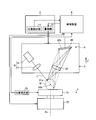
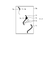
- FIG. 1 is a diagram illustrating an appearance of a shape measuring apparatus 1 according to the first embodiment.
- FIG. 2 is a schematic diagram showing a schematic configuration of the shape measuring apparatus 1 of the present embodiment.
- the optical probe 3 includes a projection device 8 and an imaging device 9 described later. Therefore, it can be said that the relative position between the object to be measured M and the optical probe 3 is the relative position between the object to be measured M and the projection device 8 or the relative position between the object to be measured M and the imaging device 9. Similarly, the relative posture between the object to be measured M and the optical probe 3 may be the relative posture between the object to be measured M and the projection device 8 or the relative posture between the object to be measured M and the imaging device 9. . Further, the device under test M is arranged on the table 71 as described later.
- the first rotating unit 53 and the second rotating unit 54 constitute a moving mechanism that allows the optical probe 3 to rotate, and changes the relative position between the optical probe 3 and the object M to be measured.
- the holding and rotating device 7 constitutes a moving mechanism that allows the object to be measured M held on the table 71 to rotate, and changes the relative position between the optical probe 3 and the object to be measured M.
- the relative posture is changed by rotating the optical probe 3 by the first rotating unit 53 and the second rotating unit 54 and rotating the object to be measured M by the holding rotating device 7.
- the shape measuring apparatus 1 may rotate only the optical probe 3 or the object to be measured M as long as it changes the relative posture.
- the shape measuring apparatus 1 may change the relative posture by rotating at least one of the optical probe 3 and the object M to be measured.
- the rotation axis for rotating the optical probe 3 and the rotation axis for rotating the measurement object M are not limited to the above description. Can be set arbitrarily.
- the longitudinal direction of the linear measurement light L can be changed by the second rotating unit 54 described above. By changing the longitudinal direction of the linear measurement light L according to the spreading direction of the surface of the object to be measured M, the measurement can be performed efficiently.
- the measurement light L irradiated to the measurement object M from the projection device 8 is projected onto the surface of the measurement object M.
- the imaging device 9 as an imaging unit captures an image of the measurement light L projected on the surface of the measurement object M.
- the imaging device 9 includes an imaging element 20 and an imaging optical system 21.
- the illumination light beam that is, the measurement light L irradiated to the measurement object M from the projection device 8 is diffusely reflected on the surface of the measurement object M, and at least a part of the diffuse reflection measurement light L is directed to the imaging optical system 21.
- the imaging optical system 21 connects the image of the measurement light L projected on the surface of the object M to be measured by the projection device 8 to the image sensor 20 by the imaging optical system 21.
- the image sensor 20 outputs an image signal corresponding to the image formed by the imaging optical system 21.
- the measurement region is a region (range) in which the image of the measurement light L is included in the imaging region.
- the shape of the object to be measured M is measured by generating a point cloud from the image of the measurement light L included in this measurement region. That is, the point group is a point on the image for calculating the coordinate value of the photographed image, and the shape of the object to be measured M is measured based on the coordinate value for each point group. Therefore, it can be said that the measurement region is a region (range) used for generating a point cloud.
- the measurement region can be restated as a point group region.
- the measurement area can be referred to as the imaging area.
- the measurement conditions may include a scan start position and a scan end position of the measurement light L irradiated by the optical probe 3.
- the measurement conditions include the relative position between the imaging device 9 (imaging unit) or the projection device 8 (projection unit) and the measurement object M, the relative orientation between the imaging device 9 or the projection device 8 and the measurement object M, and It may be at least one of the intensity of the measurement light L, the exposure and exposure time of the imaging device 9, and the measurement region.
- the condition setting unit 42 sets the measurement condition determined by the teaching of the shape measuring apparatus 1 performed by the operator operating the input unit 32 as the measurement condition, and stores the measurement condition in the storage unit 34.
- the condition setting unit 42 may read the measurement conditions stored in advance in the storage unit 34, set the measurement conditions based on the measurement conditions, or set the measurement conditions by calculation.
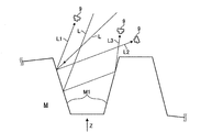
- the shape measuring apparatus 1 detects the image of the measurement light L projected on the location M1 displayed in the captured image, generates a point cloud from the detected image of the measurement light L, and determines the coordinates of the point cloud. By calculating, the shape of the object M to be measured at the location M1 is measured. Furthermore, when measuring the shape of the location M1, the shape measuring device 1 measures the object to be measured so that the diffuse reflected light L1 of the measurement light L projected onto the location M1 enters the imaging device 9. It is required to set measurement conditions such as the relative position and relative attitude between M and the optical probe 3. The reason will be described below.
- the diffuse reflected light L1 is diffusely reflected light in which the measurement light L irradiated from the projection device 8 is reflected only once at the location M1 of the object M to be measured. That is, when the measurement light L emitted from the projection device 8 is applied to the location M1, the reflected light that is diffusely reflected at the location M1 and that reaches the imaging device 9 without being reflected by other locations.
- the diffusely reflected light L1 is diffusely reflected light that is reflected only once at the location M1 and reaches the imaging device 9.
- the dimming conditions such as the intensity of the measurement light L when the imaging device 9 performs imaging are set based on the intensity of the regular reflection light L2, the dimming conditions are set based on the intensity of the diffuse reflection light L1.
- the brightness of the image of the diffuse reflected light L1 may be about 1/1000.
- the image of the measurement light L incident on the imaging device 9 is expressed by a pixel value having only a few hundred gradations, the brightness of the image of the diffuse reflection light L1 becomes too small in the captured image, and the diffuse reflection There is a possibility that the image of the light L1 cannot be detected.
- the image of the regular reflection light L2 is included in the image of the measurement light L captured by the imaging device 9, the image of the diffuse reflection light L1 cannot be detected and the point cloud of the image of the diffuse reflection light L1 is detected. May not be generated properly. Since the image of the diffuse reflected light L1 is an image representing the shape of the object M to be measured at the location M1 in the captured image, if the point cloud of the image of the diffuse reflected light L1 cannot be generated, the shape of the location M1 is measured. It cannot be done properly.
- the light diffusely reflected by the object to be measured M is incident on the other part of the object to be measured M, and the light diffusely reflected by the part may be used as the multiple reflected light L3. Since the position of the multiple reflected light L3 incident on the light receiving surface 20a of the imaging device 9 is different from the diffuse reflected light L1, the image of the multiple reflected light L3 displayed in the captured image is different from the image of the diffuse reflected light L1. Displayed in position. That is, in the captured image, the image of the diffuse reflected light L1 is an image representing the shape of the object M to be measured at the location M1, whereas the image of the multiple reflected light L3 is the image of the object M to be measured M1.
- the luminance of the image can be said to be the intensity of the light that forms the image, and thus the luminance of the image of the diffusely reflected light L1 can be said to be the intensity of the light that forms the image of the diffusely reflected light L1.
- the image of the regular reflection light L2, the image of the multiple reflection light L3, and the case where vignetting occurs are respectively relative to the object to be measured M (location M1). It was explained by changing the position and relative posture.
- the image of the regular reflection light L2, the image of the multiple reflection light L3, the vignetting, and the image In some cases, only one kind of image is captured from the diffuse reflected light L1 image with low intensity of the light, the regular reflected light L2, the multiple reflected light L3 image, the vignetting, There may be a case where two or more types of images are picked up from the diffuse reflected light L1 image having low intensity of the light that forms the image.
- the image of the regular reflection light L2 the image of the multiple reflection light L3, the vignetting, and the diffusion of the light forming the image is low
- the image of the reflected light L1 may be captured all at once.
- FIG. 5C is a diagram illustrating an example of a captured image T actually captured by the imaging device 9.
- the captured image T in FIG. 5C is an image showing an image of light captured by the imaging device 9 as described above, and is an image of light in the imaging region TR.
- the diffuse reflected light image T1 is an image of the diffuse reflected light L1 incident on the imaging device 9.
- the regular reflection light image T ⁇ b> 2 is an image of the regular reflection light L ⁇ b> 2 incident on the imaging device 9.
- the multiple reflected light image T3 is an image of the multiple reflected light L3 incident on the imaging device 9.
- FIG. 5C is a diagram illustrating an example of a captured image T actually captured by the imaging device 9.
- the captured image T in FIG. 5C is an image showing an image of light captured by the imaging device 9 as described above, and is an image of light in the imaging region TR.
- the diffuse reflected light image T1 is an image of the diffuse reflected light L1 incident on the imaging device 9.
- the vignetting image T4 is shown in the image TB.
- the vignetting image T4 is an image by vignetting. In other words, it can be said that it is an image of the diffusely reflected light L1 that is partially missing due to vignetting.
- the dotted line portion is a portion lacking due to vignetting, and the dotted line portion is not actually captured.
- the vignetting image T4 is an image of the diffusely reflected light L1 that is partially missing, it is difficult to measure the shape of the missing portion, that is, to detect a point group. Even when the brightness of the diffuse reflection light image T1 is low, the imaging device 9 cannot capture the diffuse reflection light image T1, so that it is difficult to measure the shape using the diffuse reflection light image T1.
- the diffuse reflected light image T1 having a low luminance is referred to as an inappropriate luminance image T5.
- the inappropriate luminance image T5 is, for example, a diffuse reflected light image T1 whose luminance is lower than a predetermined value.
- the predetermined value here may be set by the operator in consideration of the influence of the inappropriate luminance image T5 on the measurement accuracy of the object M to be measured, or calculated based on the design tolerance of the object M to be measured. It may be a value obtained. That is, the regular reflection light image T2, the multiple reflection light image T3, the vignetting image T4, and the inappropriate luminance image T5 may be images inappropriate for shape measurement. Moreover, it can be said that among the reflected light of the measurement light L, an image other than an image that may be an inappropriate image for shape measurement is an image suitable for shape measurement.
- the image suitable for the shape measurement is an image that is not the vignetting image T4 in the diffuse reflected light image T1 (that is, an image that has no missing portions or few missing portions due to vignetting) and has an inappropriate luminance. It can be said that the image is not the image T5.
- the vignetting image T4 is an image of the diffusely reflected light L1 that is partially lost due to vignetting.
- the missing portion (region), that is, the dotted line portion itself, is referred to as the vignetting image T4. You may call it.
- the imaging device 9 may be irradiated with light other than the measurement light L from a light source other than the projection device 8.
- Light irradiated from a light source other than the projection device 8 is also reflected by the object to be measured M, diffusely reflected light (including diffusely reflected light and multiple reflected light reflected only once by the object to be measured M), and specularly reflected light.
- the light is incident on the imaging device 9 and captured by the imaging device 9.
- These diffuse reflection light image and regular reflection light image captured by the imaging device 9 are also unsuitable for shape measurement.
- the light source other than the projection device 8 is the sun or illumination in a factory, and various light sources other than the projection device 8 may be used.
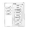
- the analysis unit 40 can easily set measurement conditions that allow the operator to accurately perform shape measurement by executing processing to be described later. To do. Hereinafter, the analysis unit 40 will be specifically described.
- the analysis unit 40 includes a design information acquisition unit 80, a condition acquisition unit 82, an image analysis unit 83, and an output unit 88.
- the analysis unit 40 uses the image analysis unit 83 to detect an image inappropriate for shape measurement from the image of the measurement light L under the measurement conditions acquired by the condition acquisition unit 82, and based on the detection result by the output unit 88.
- the detection result information is displayed on the display unit 33. The operator can easily set measurement conditions that allow accurate shape measurement by checking the display on the display unit 33.
- the design information acquisition unit 80 acquires design information of the object M to be measured.
- the design information acquisition unit 80 acquires the design information of the device under test M by reading the design information of the device under test M from the storage unit 34.
- the design information of the object M to be measured is information necessary for analysis in the image analysis unit 83 described later.
- the design information of the object M to be measured may be stored in the storage unit 34 in advance, may be acquired by communication during the process, or may be acquired by input of the input unit 32 by the operator.
- the design information includes shape data of the measurement object M and reflectance data of the measurement object M.
- the shape data is data indicating the design shape of the DUT M.
- the shape data is, for example, CAD data, mesh data, point cloud data, and the like.
- the design information acquisition unit 80 may acquire a design value indicating the shape (for example, specification values of the object M to be measured such as a gear or a turbine blade), and obtain shape data by calculation based on the design value.
- the reflectance data is data indicating the design reflectance of the object M to be measured.
- the reflectance data may be data actually measured by a separate measuring machine, or may be a value based on a material or material.
- the object to be measured M may have a plurality of regions having different surface roughnesses or materials, for example, and in this case, the reflectivity is different for each region. In such a case, the reflectance data may be a different value for each of a plurality of regions having different surface roughness and material.
- the condition acquisition unit 82 acquires measurement conditions.
- the condition acquisition unit 82 acquires the determination measurement condition, that is, the measurement condition determined by the teaching of the shape measurement apparatus 1 performed by the operator operating the input unit 32.
- the measurement conditions acquired by the condition acquisition unit 82 are used for analysis by the image analysis unit 83 described later.
- the condition acquisition unit 82 is not limited to acquiring the determined measurement condition as the measurement condition.
- the condition acquisition unit 82 may include information on light other than the measurement light L emitted from a light source other than the projection device 8 in addition to the determination measurement condition as a measurement condition used for the analysis of the image analysis unit 83.
- Information on light other than the measurement light L emitted from a light source other than the projection device 8 is referred to as other light source information.
- the other light source information includes the relative position between the light source other than the projection device 8 and the measurement object M, the relative posture between the light source other than the projection device 8 and the measurement object M, and the intensity of light from the light source other than the projection device 8.
- the other light source information may be input by the operator operating the input unit 32, the other light source information may be stored in the storage unit 34 in advance, or the other light source information may be set by calculation.
- the measurement conditions acquired by the condition acquisition unit 82 other than the other light source information may be, for example, the measurement conditions stored in advance in the storage unit 34, or the measurement conditions set by the condition acquisition unit 82 by calculation. Also good.
- the image analysis unit 83 captures an image that is inappropriate for measuring the shape of the measurement object M when the image of the light projected on the measurement object M is captured based on the design information and measurement conditions of the measurement object M. To detect. In addition, the image analysis unit 83 uses the design information and the measurement conditions of the measurement object M for an image suitable for measuring the shape of the measurement object M when an image of light projected onto the measurement object M is captured. Detect based on. That is, the image analysis unit 83 performs analysis based on the design information of the object to be measured M and the measurement conditions, and detects an image inappropriate for shape measurement and an appropriate image. The image captured by the device 9 is not analyzed.
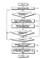
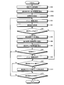
- the image analysis execution unit 84 determines whether or not the intersection of the light beam and the object to be measured M exists by calculating which position of the object to be measured M is irradiated with the light beam.
- the image analysis execution unit 84 can calculate from which direction the light beam is incident according to the measurement conditions, and also knows the shape of the object M to be measured from the design information of the object M to be measured. Whether there is an intersection with the measurement object M can be calculated. That is, the case where there is an intersection between the light beam and the object to be measured M refers to a case where the light beam is irradiated (projected) to a location where the shape of the object to be measured M is measured.
- step S12 When there is no intersection (step S12; No), that is, when the light beam is not irradiated onto the object M, the image analysis execution unit 84 ends the calculation for the light beam and proceeds to step S20 described later.
- the image analysis execution unit 84 calculates the traveling direction of the regular reflected light and the traveling direction of the diffuse reflected light based on the emission angle of the light beam at the intersection.
- the specularly reflected light is a light beam that has been specularly reflected at the intersection point with the measurement object M when the light beam has entered the intersection point with the measurement object M.
- the diffusely reflected light here is a light beam that is diffusely reflected by the light beam incident on the intersection with the object to be measured M at the intersection with the object to be measured M. Then, the image analysis execution unit 84 calculates the intensity of the regular reflection light and the diffuse reflection light based on the reflectance of the measurement object M in the design information.
- step S22 the regular reflection light and the diffuse reflection light incident on the imaging device 9 are extracted from the regular reflection light and the diffuse reflection light whose traveling direction and intensity are calculated in step S22.
- the image analysis execution unit 84 calculates the position of the imaging device 9 from the measurement conditions, and based on the position of the imaging device 9 and the traveling directions of the regular reflection light and the diffuse reflection light calculated in step S16. The regular reflection light and diffuse reflection light incident on the light are extracted. Then, the image analysis execution unit 84 calculates the incident position (coordinates) on the light receiving surface 20a for each of the regular reflection light and diffuse reflection light incident on the imaging device 9, and calculates analysis result data (step). S24).
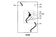
- the detection unit 86 evaluates the diffuse reflected light image P1 that has been detected as an appropriate image, thereby determining whether the diffuse reflected light image P1 includes the vignetting image P4 and the inappropriate luminance image P5.
- evaluation determination
- the vignetting image P4 and the inappropriate luminance image P5 are evaluated (determined) as being inappropriate images.
- U1 is the intensity of the light that formed the specularly reflected light image P2, more specifically, the intensity of the light of the specularly reflected light L2 that is reflected at the intersection and incident on the imaging device 9 in the analysis of the image analysis execution unit 84.
- D1 is a position (coordinates) of the light beam 20a on the light receiving surface 20a of the regular reflection light L2 reflected at the intersection and incident on the imaging device 9, and the light beam of the diffuse reflection light L1 reflected on the intersection and incident on the imaging device 9. The distance from the position (coordinates) on the light receiving surface 20a.
- the detection unit 86 calculates a diffuse reflection light image P1 in the measurement area PL used for measurement in the calculation of D1 (a diffuse reflection light image PA in FIG. 8 described later). It is preferable to calculate the distance between the light beam of the diffusely reflected light L1 and the regular reflected light image P2.
- D2 is the position of the light beam of the multiple reflected light L3 that is reflected at the intersection and incident on the imaging device 9 on the light receiving surface 20a, and the diffuse reflected light L1 that is reflected at the intersection and incident on the measurement region PL.
- the distance between the light beam and the position on the light receiving surface 20a may include the image in the calculation of the influence level V2.
- the detection unit 86 calculates an influence level V3 of the brightness of the detected diffuse reflected light image P1 (the intensity of the light that formed the diffuse reflected light image P1) (step S36), thereby causing inappropriate brightness as described later. It is evaluated whether the image P5 exists.
- the diffuse reflection light image P1 is also formed by collecting a plurality of images formed by the light of the diffuse reflection light L1 that is reflected at the intersection and incident on the imaging device 9. In this case, as shown in the following equation (3), the detection unit 86 sums up the intensities of the light beams of the diffuse reflected light L1 reflected at the intersection and incident on the imaging device 9, and the brightness of the diffuse reflected light image P1.
- U3 is the intensity of one light beam of the diffuse reflected light L1 reflected at the intersection and incident on the imaging device 9, and is reflected by one light beam of the diffuse reflected light L1 reflected at the intersection and incident on the imaging device 9. It can also be said that it is the brightness of the diffuse reflection light image P1 to be formed.
- the detection unit 86 reflects the intensity of light that forms the image of the diffuse reflection light L1 in the measurement region PL, that is, the diffuse reflection that is reflected at the intersection and enters the measurement region PL. It is preferable to calculate the influence V3 by summing up the intensities of the light rays of the light L1.
- the detection unit 86 evaluates whether or not the vignetting image P4 exists as will be described later by calculating the influence V4 of the area of the diffuse reflected light image P1 (step S38). As shown in the following equation (4), the detection unit 86 calculates a measurement range that is an area occupied by the diffuse reflected light image P1 in the imaging region PL, and sets the calculated measurement range as an influence level V4. .
- R1 is the area of the imaging region PL
- R2 is the area of the diffuse reflected light image P1 in the imaging region PL.
- the vignetting image P4 is a diffusely reflected light image P1 that is partially missing.
- the value of influence degree V0 changes by changing the measurement conditions. For example, if the intensity of the measurement light L is increased as the measurement condition with respect to the determined measurement condition, the intensity of the regular reflection light L2 becomes higher than the intensity of the regular reflection light L2 under the determined measurement condition. The degree of influence V1 becomes larger than the measured condition. Therefore, the detection unit 86 calculates the influence level V1 when the intensity of the measurement light L is increased, for example, and the influence level V1 increases, so that the luminance of the image of the diffuse reflected light L1 becomes too small and diffuses. It can be evaluated that there is a high possibility that the reflected light image P1 cannot be detected and the shape measurement cannot be appropriately performed.
- the detection unit 86 When detecting the vignetting image P4, the detection unit 86 performs detection based on the analysis result data. When detecting the vignetting image P4, the detection unit 86 calculates, as the number of incident light beams, the number of light beams of the diffusely reflected light L1 that is extracted at step S22 in FIG. . Then, the detection unit 86 calculates a value obtained by dividing the number of incident light rays by the total number of light rays divided in step S10 in FIG. 6 as an incidence ratio value. This incident ratio value can be said to be a value indicating the ratio of the light incident on the imaging device 9 as diffuse reflected light in the measurement light L.
- the detection unit 86 determines in advance the intensity of the diffusely reflected light L1 reflected at the intersection and incident on the imaging device 9, that is, U3 in Expression (3). You may detect whether it is more than predetermined intensity. Then, the detection unit 86 reflects an image of which the intensity of the light beam is greater than or equal to a predetermined intensity among the images formed by the light beam of the diffuse reflection light L1 that is reflected at the intersection and incident on the imaging device 9, and the diffuse reflection light image P1, That is, an image is detected as an appropriate image, and an image whose light intensity is smaller than a predetermined intensity is detected as an inappropriate luminance image P5, that is, an inappropriate image.
- the detection unit 86 detects the inappropriate luminance image P5 when the luminance of the diffuse reflected light image P1 is small. In other words, the detection unit 86 detects the inappropriate luminance image P5 when the luminance of the diffuse reflected light image P1 is low, in other words, when the intensity of the light beam of the diffuse reflected light L1 is small.
- the light intensity of the diffusely reflected light L1 is also reflected by, for example, the light of the diffusely reflected light L1 re-reflected in the imaging optical system 21 (lens) of the imaging device 9 and imaged as a flare. The shape measurement may not be performed properly.
- the detection part 86 detects the inappropriate image at the time of setting it as another measurement condition using the analysis result data of another measurement condition. And the detection part 86 evaluates an inappropriate image based on the detection result of the inappropriate image in another measurement condition. That is, the detection unit 86 calculates the degree of influence V0 for the inappropriate image and the appropriate image detected under different measurement conditions by the same method as the evaluation under the acquisition measurement condition.
- the detection unit 86 detects how the influence degree V0 under the different measurement conditions changes from the influence degree V0 under the acquisition measurement conditions. That is, the detection unit 86 calculates how the influence level V0 under the different measurement conditions changes with respect to the influence level V0 under the acquired measurement conditions.
- the detection unit 86 determines that the influence degree V1 is increased when the measurement condition is changed to another measurement condition when the influence degree V1 in the different measurement condition is larger than the influence degree V1 in the acquired measurement condition. For example, when the influence level V1 under the acquisition measurement condition is smaller than the threshold value (when the regular reflection light image P2 is not an inappropriate image), the influence degree V1 under another measurement condition is the influence degree V1 under the acquisition measurement condition. If it becomes larger, it can be said that the other measurement condition is a measurement condition that increases the possibility that the specularly reflected light image P2 is an inappropriate image.
- the degree of influence V1 under the acquisition measurement condition is equal to or greater than the threshold value (when the regular reflection light image P2 is an inappropriate image)
- the degree of influence V1 under another measurement condition is greater than the degree of influence V1 under the acquisition measurement condition.
- the separate measurement condition is a measurement condition that reduces the possibility that the specularly reflected light image P2 is an appropriate image. That is, when the influence level V1 under another measurement condition is larger than the influence degree V1 under the acquisition measurement condition, the possibility that the specularly reflected light image P2 becomes an improper image is high, It can be said that the possibility that the reflected light image P2 is an appropriate image is low.
- the detection unit 86 determines that the influence degree V2 is reduced when the measurement condition is changed to another measurement condition. For example, when the influence level V2 under the acquisition measurement condition is smaller than the threshold value (when the multiple reflected light image P3 is not an inappropriate image), the influence degree V2 under another measurement condition is the influence degree V2 under the acquisition measurement condition. If it becomes smaller, the influence V2 becomes smaller with respect to the threshold value under the separate measurement condition, and the separate measurement condition is a measurement condition that further reduces the possibility that the multiple reflected light image P3 is an inappropriate image. It can be said.
- the influence degree V2 under another measurement condition is smaller than the influence degree V2 under the acquisition measurement condition.
- the separate measurement condition is a measurement condition that increases the possibility that the multiple reflected light image P3 is an appropriate image. That is, when the influence V2 under the different measurement conditions is smaller than the influence V2 under the acquisition measurement conditions, the separate measurement conditions may reduce the possibility that the multiple reflected light image P3 will be an inappropriate image or multiple It can be said that there is a high possibility that the reflected light image P3 is an appropriate image.
- the detection unit 86 determines that the influence degree V3 increases when the measurement condition is changed to another measurement condition when the influence degree V3 under the different measurement condition is larger than the influence degree V3 under the acquired measurement condition. For example, when the influence level V3 under the acquisition measurement condition is smaller than the threshold value (when the inappropriate luminance image P5 is an inappropriate image), the influence degree V3 under another measurement condition is the influence degree V3 under the acquisition measurement condition. When it becomes larger, it can be said that the other measurement condition is a measurement condition that increases the possibility that the inappropriate luminance image P5 is an appropriate image (that is, it is evaluated that there is no inappropriate luminance image P5).
- the separate measurement condition is likely to cause the inappropriate luminance image P5 to be an appropriate image or inappropriate. It can be said that the possibility that the luminance image P5 is an inappropriate image is low.
- the detection unit 86 determines that the influence degree V3 becomes smaller when the measurement condition is changed to another measurement condition when the influence degree V3 under the different measurement condition is smaller than the influence degree V3 under the acquired measurement condition. For example, when the influence level V3 under the acquisition measurement condition is smaller than the threshold value (when the inappropriate luminance image P5 is an inappropriate image), the influence degree V3 under another measurement condition is the influence degree V3 under the acquisition measurement condition. If it becomes smaller, the influence level V3 is further reduced with respect to the threshold value under the separate measurement condition. Therefore, the inappropriate brightness image P5 is regarded as an appropriate image (that is, it is evaluated that there is no inappropriate brightness image P5). It can be said that this is a measurement condition with a lower possibility.
- the degree of influence under another measurement condition When V3 becomes smaller than the influence level V3 in the acquisition measurement condition, another measurement condition is a measurement in which there is a high possibility that there is an inappropriate luminance image P5 (the inappropriate luminance image P5 is regarded as an inappropriate image). It can be said that it is a condition. That is, when the influence level V3 under another measurement condition is smaller than the influence degree V3 under the acquisition measurement condition, the possibility that the inappropriate luminance image P5 is an appropriate image is low or inappropriate. It can be said that there is a high possibility that the luminance image P5 is an inappropriate image.
- the detection unit 86 determines that the influence degree V4 is increased when the measurement condition is changed to another measurement condition when the influence degree V4 under the different measurement condition is larger than the influence degree V4 under the acquired measurement condition. For example, when the influence level V4 under the acquisition measurement condition is smaller than the threshold value (when the vignetting image P4 is an inappropriate image), the influence degree V4 under another measurement condition is greater than the influence level V4 under the acquisition measurement condition. Then, it can be said that the other measurement conditions are measurement conditions that increase the possibility that the vignetting image P4 is an appropriate image (that is, it is evaluated that there is no vignetting image P4).
- the influence level V4 under the acquisition measurement condition is equal to or greater than the threshold value (when the vignetting image P4 is not an inappropriate image and is evaluated as having no vignetting image P4)
- the influence level V4 under another measurement condition is acquired and measured.
- the influence level V4 exceeds the condition, the influence level V4 is further increased with respect to the threshold value in the separate measurement condition. Therefore, the separate measurement condition includes the vignetting image P4 (the vignetting image P4 is an inappropriate image).
- this is a measurement condition that further reduces the possibility of That is, when the influence level V4 under the different measurement conditions is larger than the influence level V4 under the acquired measurement conditions, the possibility of the vignetting image P4 being an appropriate image is high or the vignetting image P4 It can be said that the possibility of being inappropriate is low.
- the detection unit 86 determines that the influence degree V4 becomes smaller when the measurement condition is changed to another measurement condition when the influence degree V4 under the different measurement condition is smaller than the influence degree V4 under the acquired measurement condition. For example, when the influence level V4 under the acquisition measurement condition is smaller than the threshold value (when the vignetting image P4 is an inappropriate image), the influence degree V4 under another measurement condition is smaller than the influence level V4 under the acquisition measurement condition. In this case, the influence V4 is further smaller than the threshold value under the separate measurement condition, and it is unlikely that the vignetting image P4 is an appropriate image (that is, it is evaluated that there is no vignetting image P4). It can be said that the measurement conditions are as follows.
- the influence level V4 under the acquisition measurement condition is equal to or greater than the threshold (when the vignetting image P4 is not an inappropriate image and it is evaluated that there is no vignetting image P4)
- the influence level V4 under another measurement condition is acquired and measured.
- the other measurement condition is a measurement condition that increases the possibility that the vignetting image P4 is present (the vignetting image P4 is an inappropriate image). That is, when the influence level V4 under the different measurement conditions is smaller than the influence level V4 under the acquired measurement conditions, the possibility of the vignetting image P4 being an appropriate image is low, or the vignetting image P4 is low. It can be said that the possibility of being considered inappropriate is high.
- the detection unit 86 calculates how the influence degree V0 when the measurement condition is changed changes. Since the evaluation result of the detection unit 86 in this embodiment evaluates an inappropriate image and an appropriate image based on a comparison between the influence level V0 and a threshold value, the detection unit 86 changes how the influence level V0 changes. By calculating this, it can also be said that the change in the evaluation result of the detection unit 86 is calculated. That is, as described above, for example, when the influence level V4 increases, the evaluation result of the detection unit 86 is less likely to cause the vignetting image P4 to be an appropriate image, or the vignetting image P4 may be an inappropriate image. It changes as if the sex becomes higher.
- change information information on the change in the influence degree V0 detected by the detection unit 86 when the measurement condition is changed is referred to as change information.
- the change information can also be referred to as change information of the evaluation result when the measurement condition is changed.
- the output unit 88 causes the display unit 33 to display an image by outputting detection result information, which is information based on the detection result of the image analysis unit 83, to the display unit 33.
- detection result information which is information based on the detection result of the image analysis unit 83.
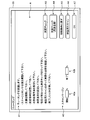
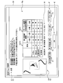
- FIG. 9A is a diagram showing an example of the menu image A.
- the output unit 88 outputs information for displaying the menu image A on the display unit 33 and causes the display unit 33 to display the menu image A when the operator sets measurement conditions for shape measurement.
- the menu image A displayed by the display unit 33 includes an instruction image A1, a scan margin setting image A2, measurement check images A3 and A4, an initial condition image A5, a verification scan image A6, and an OK image A7. .
- the analysis unit 40 performs a measurement check.
- the measurement control unit 38 performs the verification scan.
- the measurement check refers to an analysis by the image analysis unit 83.
- the image analysis execution unit 84 analyzes based on the design information acquired by the design information acquisition unit 80 and the measurement conditions acquired by the condition acquisition unit 82.
- the result data is calculated
- the detection unit 86 refers to a process of deriving a detection result by detecting an inappropriate image and an appropriate image and deriving an evaluation result by performing an evaluation based on the detection result.
- the measurement condition acquired by the condition acquisition unit 82 that is, the measurement condition for performing the analysis is the measurement condition (determined measurement condition) determined by teaching by the operator.
- the verification scan is a measurement condition (determined measurement condition) determined by teaching by the operator.
- the measurement light L from the projection device 8 is projected onto the measurement object M, and the measurement light L projected onto the measurement object M is measured.
- This refers to processing for generating a point cloud from a captured image T captured by the imaging device 9 and captured by the imaging device 9.
- each image of the menu image A will be described.
- the instruction image A1 is an image on which contents for notifying an operation to be performed by the operator in the future are displayed.
- the instruction image A1 includes information “Teaching is performed.” This is information for allowing the operator to recognize that teaching is performed.
- the instruction image A1 includes information that “please perform measurement check when setting is completed”, and is information for allowing the operator to recognize that the measurement check is performed when the measurement condition is set.
- the instruction image A1 includes information that “please check the actual point cloud by performing a verification scan”, and after the measurement check is completed, the verification scan is performed and the generated point cloud This is information for urging to confirm whether there is no problem.
- the instruction image A1 includes information “Please press OK when completed”. This completes the determination of the measurement condition and completes the verification scan. If there is no problem, the actual image is OK. This information prompts to start shape measurement.
- the menu image A may not include the instruction image A1.
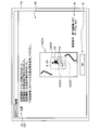
- FIG. 9B is a diagram for explaining the scan margin.
- the scan margin setting image A2 is an image that can be selected by the input unit 32 by the operation of the input unit 32 by the operator, and is an image that allows the operator to determine the scan margin.
- the scan margin is the scan start position SC1 and the scan end position SC4 of the measurement light L, that is, the position where the scan of the measurement light L starts and the position where the scan ends. This is the margin for the measurement position. That is, when measuring, the measurement light L is moved (scanned) on the locus from the scan start position SC1 to the scan end position SC4. However, the object to be measured M actually exists between the measurement start position SC2 and the measurement end position SC3.
- the scan margin is a value indicating how far the scan start position SC1 is on the upstream side of the trajectory with respect to the measurement start position SC2, and how much the scan end position SC4 is on the downstream side of the trajectory with respect to the measurement end position SC3. It is.
- the scan margin setting image A2 has a start setting image A2a and an end setting image A2b.
- the input unit 32 includes a mouse and a keyboard
- the operator operates the mouse of the input unit 32 to place the mouse cursor on the screen of the display unit 33, that is, on the menu image A, and to set the scan margin setting image. It is superimposed on the start setting image A2a or the end setting image A2b of A2.
- the start setting image A2a is an image in which it is possible to set the percentage of the scan margin at the scan start position SC1, that is, how much the scan start position SC1 is set before the measurement start position SC2.
- the end setting image A2b is an image for setting the percentage of the scan margin at the scan end position SC4, that is, how much the scan end position SC4 is behind the measurement end position SC3.
- the operator clicks a mouse button with the cursor superimposed on the start setting image A2a, and operates a keyboard included in the input unit 32 to input, for example, a numerical value, and a scan start position.
- the scan margin at SC4 can be set.
- the display unit 33 is a touch panel
- the operator touches the position where the start setting image A2a or the end setting image A2b on the display screen of the display unit 33 is displayed, so that the start setting image A2a or the end setting image is displayed.
- the scan margin may be set by selecting A2b and touching the operation panel displayed on the display screen of the display unit 33 to input a numerical value.
- the menu image A may not include the scan margin setting image A2.
- the operator touches the position where the measurement check image A3 or the measurement check image A4 is displayed on the display screen of the display unit 33, so that the measurement check image A3 or the measurement check image is displayed.
- Select A4 Note that, as an example, the measurement check image A3 is a display for executing an analysis under the measurement condition of scanning one tooth at a time as shown in FIG. 9B.
- the measurement check image A4 is a display for executing an analysis under the condition that the object to be measured M is rotated and all teeth are scanned to measure at high speed.
- the menu image A only needs to include at least one of the measurement check images A3 and A4.
- the initial condition image A5 is a display for returning the measurement conditions to the initial settings.
- the input unit 32 includes a mouse
- the operator operates the mouse of the input unit 32 to superimpose the mouse cursor on the initial condition image A5 on the screen of the display unit 33.
- the operator selects the initial condition image A5 by clicking the mouse button while the cursor is superimposed on the initial condition image A5.
- the display unit 33 is a touch panel
- the operator selects the initial condition image A5 by touching the position where the initial condition image A5 is displayed on the display screen of the display unit 33.
- the measurement condition returns to the initially set measurement condition (initial condition).
- the verification scan image A6 is a display for performing a verification scan.
- the input unit 32 includes a mouse
- the operator operates the input unit 32 to superimpose the mouse cursor on the verification scan image A6 on the screen of the display unit 33.
- the operator selects the verification scan image A6 by clicking the mouse button while the cursor is superimposed on the verification scan image A6.
- the display unit 33 is a touch panel
- the operator selects the verification scan image A6 by touching the position where the verification scan image A6 is displayed on the display screen of the display unit 33.
- the measurement control unit 38 executes the verification scan under the determined measurement conditions.
- the measurement control unit 38 causes the projection device 8 to project the measurement light L onto the measurement object M, and causes the imaging device 9 to capture an image of the measurement light L projected onto the measurement object M. And the measurement control part 38 produces
- OK image A7 is a display for ending teaching and moving to actual measurement.
- the input unit 32 includes a mouse
- the operator operates the input unit 32 to superimpose the mouse cursor on the OK image A7 on the screen of the display unit 33.
- the operator selects the OK image A7 by clicking the mouse button while the cursor is superimposed on the OK image A7.
- the display unit 33 is a touch panel
- the operator selects the OK image A7 by touching the position where the OK image A7 is displayed on the display screen of the display unit 33.
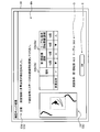
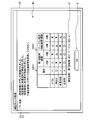
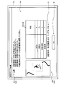
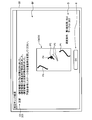
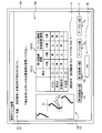
- FIG. 10 and 11 are diagrams illustrating an example of the measurement check result screen B.
- FIG. As described above, for example, the operator operates the mouse of the input unit 32 to click the measurement check images A3 and A4 by clicking the mouse button in a state where the cursor is superimposed on the measurement check images A3 and A4. select.
- the image analysis unit 83 starts the measurement check when the measurement check images A3 and A4 are selected in this way. That is, in the image analysis unit 83, the image analysis execution unit 84 performs analysis and generates analysis result data.
- the detection unit 86 detects an inappropriate image and an appropriate image based on the analysis result data, and evaluates the inappropriate image and the appropriate image based on the detection result.
- the output unit 88 outputs detection result information to the display unit 33 to display the measurement check result screen B shown in FIG.
- the detection result information is information based on the detection result of the detection unit 86.
- the measurement check result screen B displayed by the display unit 33 is a screen for displaying an image (detection result image C described later) indicating detection result information.
- the operator visually recognizes that there is an inappropriate image or an appropriate image under the measurement conditions in the measurement check by checking the detection result image C on the measurement check result screen B. be able to.
- the operator confirms the contents of the detection result image C, and adjusts the measurement conditions again, for example, when there is an inappropriate image.
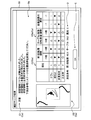
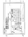
- FIG. 10 shows an example of a measurement check result screen B when an inappropriate image is detected.
- FIG. 10 shows an example in which a specularly reflected light image P2, a multiple reflected light image P3, and a vignetting image P4 are detected as inappropriate images.
- the measurement check result screen B displays a detection result image C, a measurement condition image D, and an OK image E.
- the detection result image C is an image that displays the contents of detection result information based on the detection result of the detection unit 86, in other words, an image that displays information on an inappropriate image detected by the detection unit 86.
- the output unit 88 displays the detection result image C on the display unit 33 by outputting the detection result information to the display unit 33.
- the detection result information is information based on the detection result of the detection unit 86.
- the detection result of the detection unit 86 includes the detected diffuse reflection light image P1 (detected appropriate image), the detected regular reflection light image P2 and the multiple reflection light image P3 (detected inappropriate image). Point to.
- the detection result information includes the evaluation result of the detection unit 86 as information based on the detection result.
- the evaluation result is information indicating evaluation (determination) that the image is inappropriate or appropriate, in other words, information indicating whether there is an image evaluated as inappropriate and appropriate It can be said that it is information on whether there is an image and an evaluated image.
- the evaluation result also includes information indicating what kind of inappropriate image has been evaluated, that is, the type of image that has been determined to be inappropriate by the evaluation. Therefore, the information indicating the type of the image determined to be an inappropriate image by the evaluation is that the image evaluated as the inappropriate image is the specular reflection light image P2, the multiple reflection light image P3, the vignetting image P4, and the inappropriate luminance image.
- the evaluation result includes information indicating whether or not the specular reflection light image P2 is evaluated, information indicating whether or not the multiple reflection light image P3 is evaluated, and the vignetting image P4. It has information indicating whether or not it has been evaluated, and information indicating whether or not there is an inappropriate luminance image P5.
- the evaluation result also includes information indicating whether or not an inappropriate image is not evaluated, that is, whether or not an inappropriate image is evaluated (only an appropriate image is present).
- the detection result information includes change information indicating a change in the degree of influence V0 when the measurement condition is changed.
- the detection result information also includes image data for displaying the redevelopment C0 on the display unit 33, that is, information based on analysis result data for each position on the light receiving surface 20a.
- the image data for displaying the redevelopment C0 on the display unit 33 is image data of an inappropriate image evaluated as an inappropriate image by the detection unit 86 and an appropriate image for the detection unit 86. And image data of an appropriate image evaluated. Therefore, the redevelopment C0 displayed by the image data is the redevelopment C0 including the inappropriate image and the appropriate image.
- the re-development C0 can be said to be information based on the evaluation result including the evaluated inappropriate image and the evaluated appropriate image.
- the image data for displaying the redevelopment C0 on the display unit 33 may be image data of an inappropriate image detected by the detection unit 86 and image data of an appropriate image detected by the detection unit 86. Good.
- the re-development C0 may be information based on the detection result including the detected inappropriate image and the detected appropriate image.
- the detection result information may include a detection result.
- the detection result included in the detection result information is information indicating the inappropriate image detected by the detection unit 86 and the detected appropriate image.
- the detection results included in the detection result information can be said to be information on whether there is an inappropriate image and a detected image and information on whether there is an appropriate image and a detected image.
- the detection result included in the detection result information includes information indicating what kind of inappropriate image is detected, that is, information indicating the type of image determined to be an inappropriate image by detection.
- the information indicating the type of image determined to be an inappropriate image by detection is information indicating whether the image detected as an inappropriate image is the regular reflection light image P2 or the multiple reflection light image P3. It can be said.
- the detection result included in the detection result information includes information indicating whether or not the regular reflection light image P2 is detected and information indicating whether or not the multiple reflection light image P3 is detected. .
- the detection result included in the detection result information also includes information indicating that an inappropriate image is not detected, that is, whether an inappropriate image is detected.
- the above-described evaluation result is information that evaluates whether there is an inappropriate image and an appropriate image, and there is a possibility of overlapping with this detection result. Therefore, when the evaluation result is included in the detection result information, the detection result may not be included in the detection result information. Conversely, when the detection result includes the detection result, the evaluation result does not need to be included in the detection result information. That is, the detection result information only needs to include at least one of the evaluation result and the detection result. In the following description, it is assumed that the detection result information includes the evaluation result and does not include the detection result.
- the detection result image C displayed by the display unit 33 based on the detection result information includes a redevelopment C0, a detection result notification image C1, an evaluation result image C2, and a change image C3.
- the output unit 88 outputs image data for displaying the redevelopment C0 on the display unit 33 to the display unit 33 as detection result information, and causes the display unit 33 to display the redevelopment C0.
- the redevelopment C0 in FIG. 10 includes a regular reflection light image P2, a multiple reflection light image P3, and a vignetting image P4 as inappropriate images.
- the redevelopment C0 is displayed adjacent to the evaluation result image C2 and the change image C3, but the display position is arbitrary.
- the output unit 88 outputs the evaluation result as detection result information to the display unit 33, and causes the display unit 33 to display the detection result notification image C1.
- the detection result notification image C1 is an image indicating the presence or absence of an inappropriate image.
- the image data for displaying the redevelopment C0 is also information indicating the presence or absence of an inappropriate image. Therefore, it can be said that the re-development C0 and the evaluation result image C2 described later are images indicating information on the presence or absence of inappropriate images. Therefore, in other words, it can be said that the detection result image C is an image indicating information on the presence or absence of an inappropriate image.
- the output unit 88 When the output unit 88 is evaluated as having an inappropriate image, as an evaluation result, information indicating that there is an image that has been evaluated as an inappropriate image and what inappropriate image has been evaluated. , That is, information on the evaluated inappropriate image type is output to the display unit 33.
- the detection result notification image C1 indicates that the type of inappropriate image is the vignetting image P4 and “the vignetting image P4 has been evaluated as an inappropriate image.
- the detection result notification image C1 also includes information that prompts the user to adjust the measurement conditions, such as “Please change the position and orientation of the stage with reference to the table below”.
- the detection result notification image C1 is not limited to the display using the above-described character example, and may be a display using another character string.
- the display is not limited to characters, and information indicating that an inappropriate image has been detected and information on the type of the detected inappropriate image may be displayed using, for example, a picture or a symbol.
- the detection result notification image C1 may display only information indicating the presence or absence of an inappropriate image. As shown in FIG. 10, the detection result image C is displayed in the upper area of the measurement check result screen B, but the display position is arbitrary.
- the output unit 88 outputs the evaluation result to the display unit 33 as detection result information, and causes the display unit 33 to display the evaluation result image C2.
- the evaluation result image C2 is an image indicating the evaluation result of the inappropriate image.
- the evaluation result for displaying the evaluation result image C2 is information including evaluation by the detection unit 86 for each image evaluated as an inappropriate image.
- the vignetting image P4, the regular reflection light image P2, and the multiple reflection light image P3 are evaluated as inappropriate images, and the inappropriate luminance image P5 is not evaluated as an inappropriate image. That is, it is evaluated that there is no inappropriate luminance image P5. Therefore, in the example of FIG.
- the evaluation result for displaying the evaluation result image C2 includes information indicating that the vignetting image P4, the regular reflection light image P2, and the multiple reflection light image P3 are evaluated as inappropriate images
- the inappropriate luminance image P5 includes information indicating that it is not evaluated as an inappropriate image (there is no inappropriate luminance image P5).
- the evaluation result image C2 includes the vignetting image P4 (“vignetting” in FIG. 10), the inappropriate luminance image P5 (“brightness” in FIG. 10), and the specular reflected light image P2 (FIG. 10). 10, “regular reflection”) and the multiple reflected light image P ⁇ b> 3 (“multiple reflection” in FIG. 10) are displayed as images.
- the vignetting image P4, the specular reflection light image P2, and the multiple reflection light image P3 are inappropriate images in the evaluation by the detection unit 86, and therefore, x is displayed.
- the inappropriate luminance image P5 is not indicated as an inappropriate image in the evaluation by the detection unit 86, and is displayed as “ ⁇ ” because there is no problem.
- the types of images evaluated as inappropriate images are displayed in the first column, and the images evaluated as inappropriate images displayed in the first column are displayed in the second column. It is a table on which the evaluation results (here, ⁇ or ⁇ ) are displayed.
- the evaluation result image C2 is an image indicating the evaluation by the detection unit 86 for each image evaluated as an inappropriate image
- the display method is not limited to the form of the table as shown in FIG. is there.
- the evaluation result image C2 is not limited to symbols such as ⁇ and X, but may be other symbols as long as the evaluation result by the detection unit 86 can be notified to the operator. Moreover, not only a symbol but a character string may be sufficient. In this case, for example, “OK” may be displayed if it is not evaluated as an inappropriate image, and “NG” may be displayed if it is evaluated as an inappropriate image. Further, the evaluation result image C2 may be a color display. In this case, for example, if it is not evaluated as an inappropriate image, green is displayed on the target portion of the evaluation result image C2, and if it is evaluated as an inappropriate image, red is displayed on the target portion of the evaluation result image C2. Display may be performed.
- the evaluation result is not limited to being notified to the operator by visual information as the evaluation result image C2.
- the evaluation result may be audio information that informs the operator of the presence or absence of the evaluated inappropriate image by voice. In this case, for example, sound is output to the operator through a speaker (not shown).
- the output unit 88 outputs the change information as detection result information to the display unit 33 and causes the display unit 33 to display the change image C3.
- the change image C3 is an image indicating change information.
- the change information is information on a change in the degree of influence V0 when the measurement condition is changed. More specifically, the change information for displaying the change image C3 includes the influence degree V0 of the image evaluated as an inappropriate image when the value of the measurement condition of the apparatus included in the shape measuring apparatus 1 is changed. The information indicates the tendency of change.
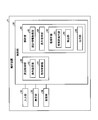
- the apparatus included in the shape measuring apparatus 1 includes a first rotating part 53, a second rotating part 54, and a table 71 (holding rotating apparatus 7) that change the relative posture, and an X moving part 50X and a Y moving that change the relative position.
- the change information includes information on how the degree of influence V0 changes when the angle of the first rotating unit 53 is changed, and how the degree of influence V0 changes when the angle of the table 71 is changed. Information about whether the image changes is included for each image evaluated as inappropriate. In addition, change information is good also as an apparatus which the shape measuring apparatus 1 has apparatuses other than the 1st rotation part 53 and the table 71.
- the change image C3 includes a case where the angle of the first rotation unit 53 is changed by +5 degrees and a case where the angle of the first rotation unit 53 is changed by -5 degrees from the current measurement conditions.
- the change tendency of each degree of influence V0 when the table 71 is changed by +5 degrees and when the table 71 is changed by -5 degrees is shown.
- the information indicating the change tendency of the influence level V4 is that the influence level V4 for the vignetting image P4 (“vignetting” in FIG. 10) is +5 degrees for the first rotation unit 53.
- the change image C3 displays a symbol indicating the upward direction as information indicating the tendency of the change in the degree of influence V4. Further, the degree of influence V4 on the vignetting image P4 becomes small when the first rotating portion 53 is changed by -5 degrees and when the table 71 is changed by -5 degrees, that is, the vignetting image P4 is appropriate. The possibility of being an image is low. Therefore, the change image C3 displays a symbol indicating the downward direction as information indicating the tendency of the change in the influence degree V4.
- the information indicating the change tendency of the influence level V3 includes the case where the influence level V3 for the inappropriate luminance image P5 (“brightness” in FIG. 10) changes the first rotating unit 53 by ⁇ 5 degrees.
- the change image C3 displays a symbol indicating an upward direction as information indicating a change tendency of the influence degree V3.
- the influence level V3 for the inappropriate luminance image P5 becomes small when the first rotating unit 53 is changed by +5 degrees and when the table 71 is changed by -5 degrees, that is, the inappropriate luminance image. P5 is likely to be an inappropriate image. Therefore, the change image C3 displays a symbol indicating a downward direction as information indicating a tendency of change in the influence degree V3.
- the information indicating the tendency of the change in the influence degree V2 includes the case where the influence degree V2 for the multiple reflected light image P3 (“multiple reflection” in FIG. 10) changes the first rotating unit 53 by ⁇ 5 degrees.
- the table 71 becomes smaller, that is, the possibility that the multiple reflected light image P3 becomes an appropriate image is increased. Therefore, the change image C3 displays a symbol indicating the upward direction as information indicating the tendency of change in the influence degree V2.
- the influence V2 on the multiple reflected light image P3 increases when the first rotating unit 53 is changed by +5 degrees and when the table 71 is changed by +5 degrees, that is, the multiple reflected light image P3. Is even less likely to be an appropriate image. Therefore, the change image C3 displays a symbol indicating a downward direction as information indicating a tendency of change in the influence degree V2.
- the information indicating the change tendency of the influence degree V1 includes the case where the influence degree V1 of the regular reflection light image P2 (“regular reflection” in FIG. 10) changes the first rotating unit 53 by +5 degrees,
- the influence V1 is low both when the first rotating unit 53 is changed by -5 degrees, when the table 71 is changed by +5 degrees, and when the table 71 is changed by -5 degrees. Therefore, the possibility that the regular reflection light image P2 is an appropriate image is high.
- the influence degree V1 is zero.
- the detection unit 86 determines that the regular reflection light image P2 is an appropriate image. Therefore, the change image C3 shown in FIG. 10 displays ⁇ as information indicating the tendency of change in the influence degree V1. Further, the change image C3 has zero influence V1 under the current measurement conditions (determined as an appropriate image), and when the measurement condition is changed, the influence V1 becomes high. Good. However, the change image C3 may display a symbol indicating an upward direction when the influence level V1 is greater than zero under the current measurement condition and the value of the influence degree V1 becomes zero when the measurement condition is changed.
- the change image C3 may display a symbol indicating a downward direction when the influence level V1 is zero under the current measurement condition and the value of the influence degree V1 increases when the measurement condition is changed. Further, the change image C3 may display a symbol indicating a downward direction when the influence level V1 is larger than zero under the current measurement condition and the value of the influence degree V1 does not change when the measurement condition is changed.
- the change image C3 is displayed in the same table as the evaluation result image C2. That is, in the example of FIG. 10, as described above, the types of images evaluated as inappropriate images are displayed in the first column of the table, and the inappropriate images displayed in the first column are displayed in the second column. The evaluation of the image to be evaluated is displayed. Then, the change image C3 displays information indicating the change tendency of each influence V0 when the first rotation unit 53 is changed by +5 degrees in the third column of the table, and in the fourth column of the table, Information indicating the tendency of change in each degree of influence V0 when the first rotating unit 53 is changed by -5 degrees is displayed, and each influence when the table 71 is changed by +5 degrees is displayed in the fifth column of the table.
- the result of the change image C3 illustrated in FIG. 10 is an example.
- the change image C3 is the same table as the evaluation result image C2, and is displayed at the center of the measurement check result screen B (below the detection result notification image C1).
- the display method and the display position of the evaluation result image C2 and the change image C3 are not limited thereto and are arbitrary.
- the evaluation result image C2 and the change image C3 may be in different tables.
- the change information may be information indicating whether the evaluation result of the inappropriate image changes when the measurement condition is changed, and is information indicating the change in the degree of influence V0 for each image evaluated as an inappropriate image. It is not limited to being.
- the change information may be information indicating whether the presence or absence of an inappropriate image changes in the evaluation result when the measurement condition is changed. For example, in the change image C3, an image that is a candidate for an inappropriate image under the current measurement condition is evaluated as an inappropriate image, and the image that is a candidate for the inappropriate image is inappropriate when the measurement condition is changed. When it is evaluated that the image is not an image, a symbol indicating an upward direction is displayed on the assumption that an inappropriate image is eliminated.
- an image that is a candidate for an inappropriate image under the current measurement conditions is not an inappropriate image. If the measurement condition is changed, the image that is a candidate for the inappropriate image is an inappropriate image. If it is evaluated, a symbol indicating a downward direction is displayed on the assumption that an inappropriate image appears.
- the change information is not limited to a symbol indicating an upward direction and a symbol indicating a downward direction, and may be displayed with another symbol if the operator can be notified of a change in the degree of influence V0 or a change in the presence or absence of an inappropriate image. May be.
- the change information may be displayed as an up arrow or a down arrow.
- the change information is not limited to a symbol but may be a character string.
- the change information may be displayed as “improvement” if the value of the influence degree V0 is improved, and “deteriorated” if the value of the influence degree V0 is deteriorated.
- the change information may be displayed as a color.
- the change information is not limited to visual information, and may be output as audio information that informs the operator of a change in the degree of influence V0 or a change in the presence or absence of an inappropriate image. In this case, the change information is output as sound to the operator through a speaker (not shown), for example.
- the change in the influence level V0 is within a predetermined threshold, visual information such as a symbol, a character string, and a color indicating that the influence level V0 does not change is displayed on the target portion of the change image C3. good.
- a symbol such as-or / indicating that the degree of influence does not change, or a character such as "no change” may be displayed.
- the operator may be notified by voice that the degree of influence V0 does not change.
- the detection result notification image C1 and the evaluation result image C2 are information displayed based on the evaluation result.
- the detection result notification image C1 and the evaluation result image C2 may be displayed based on the detection result instead of the evaluation result. Since the evaluation result is evaluated based on the influence degree V0, when the evaluation result is used, the inappropriate image and the appropriate image can be separated with high accuracy.
- the detection result is detected based on the analysis result data, that is, the intensity distribution of the image, and does not use the influence level V0. Therefore, when the detection result is used, the inappropriate image and the appropriate image can be easily separated.
- the detection result notification image C1 based on the detection result is detected as information indicating that there is an inappropriate image and a detected image (information indicating the presence or absence of the detected inappropriate image) and what inappropriate image is present. Displays information indicating whether or not Further, the evaluation result image C2 based on the detection result is information including a detection result by the detection unit 86 for each candidate image regarded as an inappropriate image. For example, when the multiple reflected light image P3 is detected, x is If the multiple reflected light image P3 is not detected, a circle is displayed. Further, when the regular reflection light image P2 is detected, x is displayed, and when the regular reflection light image P2 is not detected, ⁇ is displayed.
- the change image C3 may also be displayed based on the detection result.
- the detection result changes if the measurement conditions change. For example, consider a case where the multiple reflected light image P3 is detected as an inappropriate image under the current measurement conditions. In this case, the optical probe 3 and the measurement target are measured so that the multiple reflected light L3 is incident on the direction side outside the range of the light receiving surface 20a (imaging region PL) (the direction side away from the center of the light receiving surface 20a). When the relative position of the object M changes, the multiple reflected light L3 is less likely to enter the light receiving surface 20a, and more likely not to enter the imaging region PL. Therefore, there is a high possibility that the multiple reflected light image P3 is not detected as an inappropriate image.
- the change image C3 can also be displayed based on the detection result.
- the change information for displaying the change image C3 indicates whether the detection result of the inappropriate image changes in the detection result when the value of the measurement condition of the apparatus included in the shape measuring apparatus 1 is changed.
- Information For example, in the change image C3, an image that is a candidate for an inappropriate image under the current measurement conditions is detected as an inappropriate image, and the image that is a candidate for the inappropriate image is inappropriate when the measurement condition is changed.
- a symbol indicating the upward direction is displayed as an increased possibility that the inappropriate image will disappear.
- an image that is a candidate for an inappropriate image is not detected as an inappropriate image under the current measurement conditions, and the image that is a candidate for the inappropriate image is inappropriate when the measurement conditions are changed.
- a symbol indicating a downward direction is displayed on the assumption that an inappropriate image is likely to be detected.
- the output unit 88 outputs the current measurement condition information to the display unit 33, and causes the display unit 33 to display the measurement condition image D indicating the current measurement information information.
- the measurement condition image D is displayed below the evaluation result image C2 and the change image C3, and is an image showing information on the current measurement conditions, that is, measurement conditions set when analysis is performed.
- the measurement condition image D is an image that displays only the measurement conditions of the apparatus included in the shape measurement apparatus 1 shown in the change image C3 among the measurement conditions of each apparatus for adjusting the measurement conditions. In other words, in the example of FIG. 10, the measurement condition image D shows the current angle (60.5) of the first rotating unit 53 and the current angle (30.0) of the table 71. However, the measurement condition image D may further display the measurement conditions of apparatuses other than the apparatuses that adjust the measurement conditions shown in the change image C3.
- the OK image E is displayed below the measurement condition image D and is a display for returning the display image of the display unit 33 to the menu image A.
- the input unit 32 includes a mouse
- the operator operates the input unit 32 to superimpose the mouse cursor on the OK image E on the screen of the display unit 33.
- the operator selects the OK image E by clicking the mouse button while the cursor is superimposed on the OK image E.
- the display unit 33 is a touch panel, the operator selects the OK image E by touching the position where the OK image E is displayed on the display screen of the display unit 33.
- the output unit 88 switches the display of the display unit 33 from the measurement check result screen B to the menu image A.
- the display position of the OK image E is arbitrary.
- FIG. 11 shows an example of the measurement check result screen B when it is not evaluated that there is an inappropriate image.
- the output unit 88 notifies the detection result notification information that there is no inappropriate image. Output as information.
- the detection result notification image C ⁇ b> 1 indicates that an inappropriate image such as “Please confirm that there is no problem with the point cloud in the verification scan and complete teaching” is not detected.
- the image prompts the user to confirm the actual captured image by scanning.
- the evaluation result image C2 is evaluated as having no inappropriate image, all items are indicated by ⁇ .
- the re-development C0 is also displayed, and the image does not include an inappropriate image.
- the change image C3 is displayed even when it is evaluated that there is no inappropriate image, but it is not necessarily displayed.
- the degree of influence V1 on the specularly reflected light image P2 is obtained when the first rotating unit 53 is changed by +5 degrees, when the first rotating unit 53 is changed by -5 degrees, it is zero, and there is no possibility that the regular reflection light image P2 is an inappropriate image. Even under the current measurement conditions, the influence level V1 is zero, so it does not change.
- the change image C3 in FIG. 11 displays ⁇ for the degree of influence V1 (“regular reflection” in FIG. 11) of the regular reflection light image P2.
- the change image C3 may display a circle instead of-in this case.
- the display of the change image C3 in FIG. 11 is the same as that in FIG. 10 in other points.
- FIG. 12 is a flowchart illustrating a flow when setting measurement conditions according to the present embodiment.
- the control unit 36 acquires the design information of the object M to be measured by the design information acquisition unit 80 (step S50).
- the output unit 88 causes the display unit 33 to display the menu image A (step S52).
- the design information of the object to be measured M may be acquired at any time before the analysis.
- the operator refers to, for example, the instruction image A1, etc., performs teaching, adjusts the measurement condition by operating the input unit 32 and inputting the measurement condition, and performs measurement. Determine the conditions.
- the analysis unit 40 acquires the measurement condition determined by the adjustment by the condition acquisition unit 82 (step S54), and determines whether the measurement check execution is instructed (step S56).
- the control unit 36 determines that the measurement check execution has been instructed (step S56; Yes), and the image analysis execution unit 84
- the analysis result data is calculated (step S58), and the detection unit 86 derives the detection result and the evaluation result (step S60).
- the image analysis execution unit 84 calculates the analysis result data by executing the process shown in FIG. Then, the detection unit 86 derives a detection result by detecting an inappropriate image and an appropriate image based on the analysis result data. Moreover, the detection part 86 derives an evaluation result by performing evaluation based on a detection result.
- the output unit 88 may display an image indicating that the analysis is being performed by switching the image from the menu image A while the processing of the image analysis execution unit 84 and the detection unit 86 is being performed. An image indicating that the analysis is being executed may be displayed so as to be superimposed on A.
- step S56 when the measurement check image A3 (or A4) on the menu image A is not selected by the operator, that is, when the measurement check is not executed (step S56; No), the analysis unit 40 proceeds to step S68 to be described later for verification. It is determined whether or not an instruction for executing the scan is instructed.
- the control unit 36 determines whether or not the verification scan execution is instructed when the measurement check is not executed on the menu image A, but is not limited thereto. That is, the control unit 36 may perform the determination whether the measurement check is instructed and the determination whether the verification scan is instructed in parallel. In other words, the control unit 36 executes the measurement check when the measurement check image A3 (or A4) is selected by the operator, and performs the verification when the verification scan image A6 is selected by the operator. A scan may be executed.
- the control unit 36 causes the output unit 88 to output the detection result information to the display unit 33 and display the measurement check result screen B on the display unit 33 (step S62).
- the operator confirms the detection result image C on the measurement check result screen B and determines whether the determined measurement condition needs to be further changed.
- the analysis unit 40 determines whether a confirmation end instruction has been given in a state where the measurement check result screen B is displayed (step S64).
- the control unit 36 determines that the confirmation end instruction has been given (step S64; Yes), and the output unit 88 causes the measurement check result screen B to be determined.
- step S66 Is switched to the menu image A, and the menu image A is displayed on the display unit 33 (step S66).
- the operator operates the input unit 32 to determine a new measurement condition.
- the operator evaluates that there is no inappropriate image in the detection result image C, for example, the operator does not determine a new measurement condition.
- whether to determine new measurement conditions depends on the operator's judgment, so if it is evaluated that there is an inappropriate image, it is not necessary to determine new measurement conditions, and if there is no inappropriate image. When evaluated, new measurement conditions may be determined.
- step S64 determines that the confirmation end instruction has not been given (step S64; No), and the operator still has the measurement check result. Assuming that the screen B is being confirmed, a confirmation end instruction is awaited in step S64.
- control unit 36 determines whether a new measurement condition has been determined by the operator (step S67). For example, when the measurement condition determined by the operator is newly stored in the storage unit 34, the control unit 36 determines that the new measurement condition has been determined.
- the determination method that the new measurement condition is determined is not limited to this, and is arbitrary. For example, when the operator inputs the determination of the new measurement condition to the input unit 32, the control unit 36 It may be determined that a new measurement condition has been determined.
- the control unit 36 returns to step S54, acquires the new measurement condition by the condition acquisition unit 82, and continues the subsequent processing. That is, when the operator selects the measurement check image A3 (or A4) after determining a new measurement condition, the control unit 36 performs analysis under the new measurement condition and displays the measurement result check image B.
- step S67; Yes the control unit 36 determines whether there is a verification scan execution instruction with the menu image A displayed (step S68), and the operator When the verification scan image A6 is selected, it is determined that the verification scan execution instruction has been received (step S68; Yes), and the measurement control unit 38 executes the verification scan and performs the actual measurement under the set measurement conditions.
- the captured image T is captured, and the shape measurement of the object M to be measured is executed. That is, a point cloud of the device under test M is generated (step S70). The operator confirms the result (point group) of the shape measurement and determines whether the set measurement condition is appropriate.
- control unit 36 determines whether the determination of the measurement conditions has been completed, that is, whether teaching has been completed (step S72).
- the control unit 36 proceeds to step S72.
- the OK image A7 is selected on the menu image A by the operator
- the control unit 36 determines that the measurement conditions have been determined, that is, teaching has been completed (step S72; Yes)
- the measurement condition setting process ends.
- the OK image A7 is not selected by the operator on the menu image A
- the control unit 36 determines that the measurement condition is determined, that is, teaching is not completed (step S72; No) returns to step S52, and returns to the menu image. Continue to display A.
- step S54 the control unit 36 acquires a new measurement condition in step S54, and repeats the subsequent processing.
- the control unit 36 may not necessarily execute the verification scan, and thus may omit steps S68 and S70.
- the step after step S66 is step S72.
- the control unit 36 displays information based on the detection result on the measurement check result screen B as the detection result image C. It can be said that the information based on the detection result is information derived by analysis as to whether an inappropriate image is included when the captured image T is actually captured under the measurement conditions acquired by the condition acquisition unit 82. Therefore, the operator can easily determine whether the measurement condition is appropriate by confirming the detection result image C, and easily set the measurement condition that allows accurate shape measurement. Can do.
- control unit 36 can execute a measurement check in the analysis unit 40 and a verification scan in the measurement control unit 38. Therefore, in addition to confirming information based on the detection result, the operator confirms the point cloud generated from the actual captured image T under the determined measurement condition, thereby further confirming whether the measurement condition is appropriate. It can be judged with accuracy.
- the control unit 36 also displays a change image C3.
- the change image C3 is information indicating how the evaluation result changes when the measurement condition is changed. This trend of change is likely to be consistent with actual measurements. Therefore, the operator can easily and accurately determine how to change the measurement conditions by checking the change image C3.
- the control unit 36 (image analysis apparatus) according to the present embodiment includes the image analysis unit 83 and the output unit 88.
- the image analysis unit 83 measures the design information of the object to be measured M and the image inappropriate for measuring the shape of the object to be measured M when the image by the light projected onto the object to be measured M is captured. Detect based on conditions.
- the output unit 88 outputs detection result information that is information based on the detection result of the image analysis unit 83.
- the control unit 36 outputs detection result information, that is, information based on the inappropriate image detection result. Therefore, according to the control unit 36, the output detection result information is displayed on another device, for example, the display unit 33, so that the operator can check the detection result information, that is, the detection result image C.
- the operator can confirm whether there is a possibility that an inappropriate image is included or whether an appropriate image is included. Therefore, according to the control unit 36, the operator can easily determine whether the set measurement conditions are appropriate, and can easily set the measurement conditions that can accurately perform the shape measurement. it can.
- the analysis device 4 includes the display unit 33, and the output unit 88 outputs the detection result information to the display unit 33.
- the output unit 88 may output detection result information to a storage unit (for example, the storage unit 34) provided in the analysis devices 4 and 4A, and the storage unit may store the output detection result information.
- the storage unit may be accessed from an operator's PC (personal computer) or a terminal such as a tablet connected to the analysis apparatuses 4 and 4A via a network, and the detection result information may be acquired via the network. And you may display the acquired detection result information on the display part (display) of PC.
- the image analysis unit 83 evaluates the detected inappropriate image.
- the output part 88 outputs the evaluation result of the detected inappropriate image to the display part 33 as detection result information. Therefore, according to this control unit 36, the operator can confirm the evaluation result of the inappropriate image under the set measurement conditions by confirming the detection result image C, and can more easily determine whether the set conditions are appropriate. Can be judged.
- the image analysis unit 83 detects an image (appropriate image) suitable for measuring the shape of the measurement object M from the image of the measurement light L projected on the measurement object M based on the design information and the measurement conditions. To do. Then, the image analysis unit 83 evaluates the detected inappropriate image based on at least one of the relative distance between the detected inappropriate image and the detected appropriate image and the luminance of the detected inappropriate image. Since the control unit 36 evaluates the inappropriate image based on the intensity of light that forms the inappropriate image and the relative distance from the appropriate image, the controller 36 preferably calculates the influence of the inappropriate image on the appropriate image. By displaying the evaluation result on the display unit 33, it is possible to inform the operator and to make it easier for the operator to determine whether the setting condition is appropriate.
- the image analysis unit 83 preferably evaluates the detected inappropriate image based on both the relative distance between the detected inappropriate image and the detected appropriate image and the luminance of the detected inappropriate image. By performing the evaluation in this way, the control unit 36 can evaluate the inappropriate image with high accuracy and appropriately calculate the influence of the inappropriate image on the appropriate image.
- the image analysis unit 83 calculates a change in the evaluation result of the inappropriate image when the measurement condition is changed.
- the output unit 88 outputs change information indicating the change in the inappropriate image evaluation result when the measurement condition is changed to the display unit 33 as detection result information.
- the control unit 36 can transmit to the operator by displaying on the display unit 33 whether the evaluation result of the inappropriate image changes when the measurement condition is changed. Therefore, according to the control unit 36, the operator can obtain a guideline on how to adjust the measurement conditions by checking the change in the evaluation result, so that the shape measurement can be accurately performed. It is possible to easily set the measurement conditions that can be used.
- the output unit 88 further displays the redevelopment C0 reproduced from the image analysis result data on the screen on which the detection result information is displayed, that is, the measurement check result screen B.
- the output unit 88 displays the actual measurement light L projected on the measurement object M, which is imaged by the imaging device 9 under the measurement conditions used for detection of the detection result information, on the screen on which the detection result information is displayed.
- An image, that is, a captured image T may be displayed.
- the control unit 36 captures an actual image of the measurement light L under the same measurement condition as that of the detection result image C, and uses this to detect the detection result image C. Is displayed on the same screen.
- the operator can confirm the actual captured image T together with the detection result image C, and thus can more easily recognize that there is an inappropriate image.
- the output unit 88 may display the captured image T instead of the redevelopment C0, or may display the captured image T so as to be superimposed on the redevelopment C0.
- the measurement conditions include the relative position between the imaging device 9 or the projection device 8 (irradiation unit) that irradiates the measurement light L and the measurement object M, the projection device 8 that irradiates the imaging device 9 or the measurement light L, and the measurement target. It includes at least one of the relative posture with the object M, the intensity of the measurement light L irradiated to the object M, and the measurement region.
- region is an area
- the measurement conditions include the relative position between the imaging device 9 or the projection device 8 (irradiation unit) that irradiates the measurement light L and the measurement object M, the projection device 8 that irradiates the imaging device 9 or the measurement light L, and the measurement target. It is preferable to include both of the relative posture with the object M. According to the control unit 36, the operator can appropriately set these measurement conditions.
- the image analysis unit 83 as inappropriate images, an image generated by multiple reflection (multiple reflection light image P3), an image generated by regular reflection (regular reflection light image P2), and an image by vignetting (vignetting). At least one of the image P4) and the inappropriate luminance image P5 is detected.
- the inappropriate luminance image P5 is an image in which the intensity of light forming the image (or the luminance of the image) is lower than a predetermined value among the diffusely reflected light L1 image (diffuse reflected light image P1) reflected once.
- the image forming light intensity may be an image outside a predetermined range.
- the control unit 36 can appropriately detect an inappropriate image by setting such an image as an inappropriate image, and can cause the operator to appropriately set measurement conditions.
- the predetermined value here may be set by the operator in consideration of the influence of the inappropriate luminance image T5 on the measurement accuracy of the measurement object M, or based on the design tolerance of the measurement object M. It may be a value calculated by
- the detection unit 86 evaluates the image as the inappropriate luminance image P5 when the luminance of the diffuse reflected light image P1 is low, in other words, when the intensity of the light beam of the diffuse reflected light L1 is small.
- the light intensity of the diffusely reflected light L1 is also reflected by, for example, the light of the diffusely reflected light L1 re-reflected in the imaging optical system 21 (lens) of the imaging device 9 and imaged as a flare. The shape measurement may not be performed properly.
- the detection unit 86 may use the inappropriate luminance image P5 even when the intensity of the diffuse reflected light L1 is too high (the luminance of the diffuse reflected light image P1 is too high). In this case, when the influence V3, which is the total value of the intensity of the diffuse reflected light L1 (or the brightness of the diffuse reflected light image P1), is outside the predetermined range, the detection unit 86 detects the light of the diffuse reflected light L1.
- the image (diffuse reflected light image P1) formed in (1) is evaluated as an inappropriate luminance image P5.
- the detection unit 86 performs diffusion when the influence degree V3, which is the total value of the intensity of the diffuse reflected light L1 (or the brightness of the diffuse reflected light image P1) in the formula (3), is within a predetermined range.
- the image (diffuse reflected light image P1) formed by the reflected light L1 is evaluated as having no inappropriate luminance image P5, that is, the inappropriate luminance image P5 is not an inappropriate image.
- the predetermined range is a numerical range between the predetermined upper limit value and the predetermined lower limit value.
- the upper limit value and the lower limit value affect the measurement accuracy of the object M to be measured by the inappropriate luminance image P5. May be set by the operator.
- the image analysis unit 83 calculates image analysis result data (intensity distribution) when the image of the measurement light L projected onto the measurement object M is captured by the imaging unit (imaging device 9) under the measurement conditions. By doing so, an inappropriate image is detected. Then, the image analysis unit 83 generates an inappropriate image from an image other than the image of the measurement light L (diffuse reflected light image P1) reflected only once on the measurement object M based on the analysis result data (intensity distribution). To detect.
- image analysis result data intensity distribution
- the analysis device 4 includes a control unit 36 and a display unit 33 (display device) that displays the detection result image C.
- a control unit 36 controls the analysis device 4 to display the detection result image C.
- a display unit 33 displays the detection result image C.
- the shape measuring apparatus 1 includes a control unit 36, an input unit 32 that receives an input from an operator, a projection device 8 (projection unit) that projects the measurement light L onto the object to be measured M, and An optical probe 3 having an imaging device 9 (imaging unit) that captures an image of the measurement light L projected on the measurement object M, and a condition setting unit 42 that sets measurement conditions by input to the input unit 32.
- a control unit 36 an input unit 32 that receives an input from an operator
- a projection device 8 projection unit
- An optical probe 3 having an imaging device 9 (imaging unit) that captures an image of the measurement light L projected on the measurement object M
- condition setting unit 42 that sets measurement conditions by input to the input unit 32.
- the image analysis method includes an image analysis step by the image analysis unit 83 and an output step by the output unit 88.
- an inappropriate image is detected based on design information of the object to be measured M and measurement conditions.
- the output step outputs detection result information that is information based on the detection result in the image analysis step. According to this method, it is possible to easily set measurement conditions that allow accurate shape measurement.
- the program according to the present embodiment causes a computer such as the analysis device 4 to execute this image analysis method.
- the measurement condition determination method includes the image analysis method described above and a measurement condition determination step that determines the measurement condition based on the detection result information output in the output step. According to this measurement condition determination method, it is possible to easily set measurement conditions that allow accurate shape measurement.
- the shape measuring method includes the above-described measurement condition determining method and a shape measuring step for measuring the shape of the measurement object M under the measurement conditions determined in the measurement condition determining step. According to this shape measuring method, it is possible to perform shape measurement under appropriately set measurement conditions, and therefore it is possible to suppress a decrease in measurement accuracy.
- control unit 36 may realize the functions of the measurement control unit 38 and the analysis unit 40 by hardware, or may realize these functions by software.
- the control unit 36 may realize part of the functions of the measurement control unit 38 and the analysis unit 40 by hardware, and other part of these functions by software.
- the control part 36 may be implement
- the control unit 36 may be realized by integrating all the functions of the measurement control unit 38 and the analysis unit 40 or may be realized without integrating some of them.
- the output unit 88 causes the display unit 33 to display the detection result image Ca on the measurement check result screen Ba according to the modification shown in FIG.
- the detection result image Ca includes a change image C3a.
- the change image C3a is different from the change image C3 of the first embodiment in the parameters of the measurement conditions. That is, the output unit 88 may change the parameter of the measurement condition in the change information from the first embodiment.
- the change image C3a has the imaging device 9 as an apparatus which the shape measuring apparatus 1 has. Then, the exposure is changed as a measurement condition of the imaging device 9.
- the exposure here is an EV (Exposure value) value.
- the information indicating the change in the influence level V3 (“brightness” in FIG. 13) displayed by the change image C3a indicates the upward direction because the influence level V3 increases when the exposure becomes +1.
- the influence level V3 is low, and the symbol indicates the downward direction.
- the information indicating the change in the degree of influence V2 (“multiple reflection” in FIG. 13) displayed by the change image C3a is a symbol indicating the downward direction because the degree of influence V2 is high when the exposure is +1.
- the influence degree V2 becomes low, and thus becomes a symbol indicating the upward direction.
- the influence degree V4 (“vignetting” in FIG.
- the output unit 88 is different from the first embodiment in that the redevelopment C0 is not displayed on the measurement check result screen Bc according to the modification shown in FIG. That is, the output unit 88 may not include image data for displaying the redevelopment C0 in the detection result information. Thus, even when the redevelopment C0 is not displayed, the other detection result image C is displayed, so that the operator can recognize whether there is an inappropriate image.
- the output unit 88 displays the detection result image Ce on the measurement check result screen Be according to the modification shown in FIG.
- the detection result image Ce is different from the first embodiment in that it includes an identification image C4. That is, the output unit 88 may include identification information for displaying the identification image C4 in the detection result information.
- the identification information is information for identifying an inappropriate image in the redevelopment C0. Furthermore, the identification information is information for identifying an inappropriate image and an appropriate image. When there are a plurality of types of inappropriate images, the identification information is information for identifying inappropriate images. For example, when the specular reflection light image P2, the multiple reflection light image P3, and the vignetting image P4 are detected as inappropriate images, the information for identifying the inappropriate images is any of the inappropriate reflection images.
- P2 is information indicating which inappropriate image is the multiple reflected light image P3.
- the control unit 36 may derive in advance the detection result and the evaluation result when the measurement condition is changed, or performs analysis to detect the detection result and the evaluation each time an instruction to change the measurement condition is received.
- the result may be derived. Note that the modified examples shown in FIGS. 13 to 20 described above can also be applied to second and third embodiments described later.
- the repair device 205 performs reworking of the structure (Step S107), and the process of Step S103 is performed. Return to processing.
- the inspection unit 211 determines that the created structure cannot be repaired (No in step S106)
- the structure manufacturing system 200 ends the process.
- the structure manufacturing system 200 ends the process of the flowchart shown in FIG.
- the shape measuring device 1 is a device that measures the three-dimensional shape of the object M using the light cutting method.
- the shape measuring device 1 uses the light cutting method.
- the present invention is not limited to the device used, and can be applied to a shape measuring device that receives light from the device under test M (for example, from an image of the device under test M) and measures the shape of the device under test M.
- a shape measuring device that measures the three-dimensional shape of the object to be measured M from an image obtained by projecting striped or dot pattern light onto the object to be measured M, or an object to be measured from the image of the object to be measured M.
- the present invention can be applied to an existing shape measuring apparatus such as an existing image measuring apparatus that measures the two-dimensional shape (size) of M. Further, the present invention can be applied to existing inspection devices and measuring devices other than the shape measuring device.
Landscapes
- Physics & Mathematics (AREA)
- General Physics & Mathematics (AREA)
- Engineering & Computer Science (AREA)
- Computer Vision & Pattern Recognition (AREA)
- Length Measuring Devices By Optical Means (AREA)
- Image Processing (AREA)
- Image Analysis (AREA)
Priority Applications (7)
| Application Number | Priority Date | Filing Date | Title |
|---|---|---|---|
| US16/976,054 US20210072019A1 (en) | 2018-02-27 | 2018-02-27 | Image analysis device, analyis device, shape measurement device, image analysis method, measurement condition determination method, shape measurement method, and program |
| CN201880092731.XA CN112055803B (zh) | 2018-02-27 | 2018-02-27 | 像解析装置、解析装置、形状测定装置、像解析方法、测定条件决定方法、形状测定方法及程序 |
| CN202311327865.4A CN117419657A (zh) | 2018-02-27 | 2018-02-27 | 像解析装置、解析装置、形状测定装置、像解析方法、测定条件决定方法、形状测定方法及程序 |
| PCT/JP2018/007381 WO2019167150A1 (ja) | 2018-02-27 | 2018-02-27 | 像解析装置、解析装置、形状測定装置、像解析方法、測定条件決定方法、形状測定方法及びプログラム |
| EP18907727.4A EP3760970A4 (en) | 2018-02-27 | 2018-02-27 | IMAGE ANALYSIS DEVICE, ANALYSIS DEVICE, SHAPE MEASUREMENT DEVICE, IMAGE ANALYSIS METHOD, MEASUREMENT CONDITION DETERMINATION METHOD, SHAPE MEASUREMENT METHOD AND PROGRAM |
| JP2020503145A JP7367668B2 (ja) | 2018-02-27 | 2018-02-27 | 像解析装置、解析装置、形状測定装置、像解析方法、測定条件決定方法、形状測定方法及びプログラム |
| JP2023176918A JP2023176008A (ja) | 2018-02-27 | 2023-10-12 | 像解析装置、解析装置、形状測定装置、像解析方法、測定条件決定方法、形状測定方法及びプログラム |
Applications Claiming Priority (1)
| Application Number | Priority Date | Filing Date | Title |
|---|---|---|---|
| PCT/JP2018/007381 WO2019167150A1 (ja) | 2018-02-27 | 2018-02-27 | 像解析装置、解析装置、形状測定装置、像解析方法、測定条件決定方法、形状測定方法及びプログラム |
Publications (1)
| Publication Number | Publication Date |
|---|---|
| WO2019167150A1 true WO2019167150A1 (ja) | 2019-09-06 |
Family
ID=67806117
Family Applications (1)
| Application Number | Title | Priority Date | Filing Date |
|---|---|---|---|
| PCT/JP2018/007381 WO2019167150A1 (ja) | 2018-02-27 | 2018-02-27 | 像解析装置、解析装置、形状測定装置、像解析方法、測定条件決定方法、形状測定方法及びプログラム |
Country Status (5)
| Country | Link |
|---|---|
| US (1) | US20210072019A1 (zh) |
| EP (1) | EP3760970A4 (zh) |
| JP (2) | JP7367668B2 (zh) |
| CN (2) | CN112055803B (zh) |
| WO (1) | WO2019167150A1 (zh) |
Families Citing this family (1)
| Publication number | Priority date | Publication date | Assignee | Title |
|---|---|---|---|---|
| JP2022191675A (ja) * | 2021-06-16 | 2022-12-28 | 株式会社ミツトヨ | 光学式プローブ及び形状測定装置 |
Citations (7)
| Publication number | Priority date | Publication date | Assignee | Title |
|---|---|---|---|---|
| US6075605A (en) | 1997-09-09 | 2000-06-13 | Ckd Corporation | Shape measuring device |
| US20100165346A1 (en) * | 2008-12-26 | 2010-07-01 | Hermes Microvision, Inc. | Apparatus for detecting a sample |
| JP2014106099A (ja) * | 2012-11-27 | 2014-06-09 | Keyence Corp | 形状測定装置、形状測定方法および形状測定プログラム |
| JP2014145735A (ja) * | 2013-01-30 | 2014-08-14 | Nikon Corp | 形状測定装置、構造物製造システム、評価装置、形状測定方法、構造物製造方法、及び形状測定プログラム |
| JP2015068654A (ja) | 2013-09-26 | 2015-04-13 | 株式会社ニコン | 形状測定装置、構造物製造システム及び形状測定用コンピュータプログラム |
| JP2015197312A (ja) * | 2014-03-31 | 2015-11-09 | キヤノン株式会社 | 情報処理装置、情報処理装置の制御方法、把持システムおよびプログラム |
| JP2017173063A (ja) * | 2016-03-23 | 2017-09-28 | 日立オートモティブシステムズ株式会社 | 検査装置及び検査方法 |
Family Cites Families (17)
| Publication number | Priority date | Publication date | Assignee | Title |
|---|---|---|---|---|
| JP3765061B2 (ja) * | 1995-05-19 | 2006-04-12 | 株式会社ニコン | 多次元形状の座標計測機用オフライン・ティーチング・システム |
| JP4797593B2 (ja) * | 2005-03-10 | 2011-10-19 | 富士ゼロックス株式会社 | 光沢測定装置及びプログラム |
| JP2010256253A (ja) | 2009-04-27 | 2010-11-11 | Topcon Corp | 三次元計測用画像撮影装置及びその方法 |
| US9179106B2 (en) * | 2009-12-28 | 2015-11-03 | Canon Kabushiki Kaisha | Measurement system, image correction method, and computer program |
| JP6004851B2 (ja) * | 2012-09-11 | 2016-10-12 | 株式会社キーエンス | 形状測定装置、形状測定方法および形状測定プログラム |
| JP5956911B2 (ja) | 2012-11-05 | 2016-07-27 | 株式会社キーエンス | 形状測定装置、形状測定方法および形状測定プログラム |
| JP5956932B2 (ja) | 2013-01-08 | 2016-07-27 | 株式会社キーエンス | 形状測定装置、形状測定方法および形状測定プログラム |
| WO2014156723A1 (ja) * | 2013-03-27 | 2014-10-02 | 株式会社ニコン | 形状測定装置、構造物製造システム、形状測定方法、構造物製造方法、及び形状測定プログラム |
| JP6128219B2 (ja) * | 2013-07-19 | 2017-05-17 | 株式会社ニコン | 形状測定装置、構造物製造システム、形状測定方法、構造物製造方法、形状測定プログラム、及び記録媒体 |
| WO2015025403A1 (ja) | 2013-08-22 | 2015-02-26 | 富士機械製造株式会社 | 基板の生産作業方法、基板の撮像条件決定方法、および基板の生産作業装置 |
| JP6364777B2 (ja) * | 2014-01-10 | 2018-08-01 | 凸版印刷株式会社 | 画像データ取得システム及び画像データ取得方法 |
| US10482592B2 (en) * | 2014-06-13 | 2019-11-19 | Nikon Corporation | Shape measuring device, structured object manufacturing system, shape measuring method, structured object manufacturing method, shape measuring program, and recording medium |
| JP6377582B2 (ja) | 2015-08-06 | 2018-08-22 | 株式会社リガク | X線分析の操作ガイドシステム、操作ガイド方法、及び操作ガイドプログラム |
| WO2017162777A1 (de) * | 2016-03-22 | 2017-09-28 | Fraunhofer-Gesellschaft zur Förderung der angewandten Forschung e.V. | Vorrichtung zur 3-dimensionalen vermessung eines objekts, verfahren und computerprogramm |
| JP6894672B2 (ja) * | 2016-05-18 | 2021-06-30 | キヤノン株式会社 | 情報処理装置、情報処理方法、プログラム |
| JP6161775B2 (ja) * | 2016-09-06 | 2017-07-12 | 株式会社キーエンス | 形状測定装置、形状測定方法および形状測定プログラム |
| EP3441712A1 (de) * | 2017-08-08 | 2019-02-13 | Klingelnberg AG | Koordinaten-messvorrichtung mit optischem sensor und entsprechendes verfahren |
-
2018
- 2018-02-27 JP JP2020503145A patent/JP7367668B2/ja active Active
- 2018-02-27 EP EP18907727.4A patent/EP3760970A4/en active Pending
- 2018-02-27 US US16/976,054 patent/US20210072019A1/en active Pending
- 2018-02-27 CN CN201880092731.XA patent/CN112055803B/zh active Active
- 2018-02-27 WO PCT/JP2018/007381 patent/WO2019167150A1/ja unknown
- 2018-02-27 CN CN202311327865.4A patent/CN117419657A/zh active Pending
-
2023
- 2023-10-12 JP JP2023176918A patent/JP2023176008A/ja active Pending
Patent Citations (7)
| Publication number | Priority date | Publication date | Assignee | Title |
|---|---|---|---|---|
| US6075605A (en) | 1997-09-09 | 2000-06-13 | Ckd Corporation | Shape measuring device |
| US20100165346A1 (en) * | 2008-12-26 | 2010-07-01 | Hermes Microvision, Inc. | Apparatus for detecting a sample |
| JP2014106099A (ja) * | 2012-11-27 | 2014-06-09 | Keyence Corp | 形状測定装置、形状測定方法および形状測定プログラム |
| JP2014145735A (ja) * | 2013-01-30 | 2014-08-14 | Nikon Corp | 形状測定装置、構造物製造システム、評価装置、形状測定方法、構造物製造方法、及び形状測定プログラム |
| JP2015068654A (ja) | 2013-09-26 | 2015-04-13 | 株式会社ニコン | 形状測定装置、構造物製造システム及び形状測定用コンピュータプログラム |
| JP2015197312A (ja) * | 2014-03-31 | 2015-11-09 | キヤノン株式会社 | 情報処理装置、情報処理装置の制御方法、把持システムおよびプログラム |
| JP2017173063A (ja) * | 2016-03-23 | 2017-09-28 | 日立オートモティブシステムズ株式会社 | 検査装置及び検査方法 |
Non-Patent Citations (1)
| Title |
|---|
| See also references of EP3760970A4 |
Also Published As
| Publication number | Publication date |
|---|---|
| EP3760970A1 (en) | 2021-01-06 |
| JPWO2019167150A1 (ja) | 2021-02-18 |
| CN112055803B (zh) | 2024-02-13 |
| US20210072019A1 (en) | 2021-03-11 |
| EP3760970A4 (en) | 2021-10-06 |
| CN117419657A (zh) | 2024-01-19 |
| JP7367668B2 (ja) | 2023-10-24 |
| JP2023176008A (ja) | 2023-12-12 |
| CN112055803A (zh) | 2020-12-08 |
Similar Documents
| Publication | Publication Date | Title |
|---|---|---|
| JP6350657B2 (ja) | 形状測定装置、構造物製造システム、形状測定方法、構造物製造方法、形状測定プログラム、及び記録媒体 | |
| JP6044705B2 (ja) | 形状測定装置、構造物製造システム、形状測定方法、構造物製造方法、及び形状測定プログラム | |
| JP5217221B2 (ja) | 溶接部の表面欠陥形状検出方法及びコンピュータプログラム | |
| JP2021177186A (ja) | 三次元画像処理装置及び三次元画像処理方法 | |
| JP5758090B2 (ja) | 形状検査装置及び形状検査方法 | |
| JP6649802B2 (ja) | 三次元画像検査装置、三次元画像検査方法、三次元画像検査プログラム及びコンピュータで読み取り可能な記録媒体並びに記録した機器 | |
| US20160261791A1 (en) | Optical Displacement Measurement System, Imaging Condition Optimization Method, And Imaging Condition Optimization Program | |
| JP2016130663A (ja) | 検査装置及び検査装置の制御方法 | |
| WO2022050279A1 (ja) | 三次元計測装置 | |
| WO2012057284A1 (ja) | 三次元形状測定装置、三次元形状測定方法、構造物の製造方法および構造物製造システム | |
| JP2023176008A (ja) | 像解析装置、解析装置、形状測定装置、像解析方法、測定条件決定方法、形状測定方法及びプログラム | |
| JP2009192332A (ja) | 3次元処理装置における3次元データの表示制御方法および3次元処理装置 | |
| JP7516219B2 (ja) | 測定装置、制御装置、制御方法及びプログラム | |
| JP6248510B2 (ja) | 形状測定装置、構造物製造システム、形状測定方法、構造物製造方法、形状測定プログラム、及び記録媒体 | |
| JP2023176008A5 (zh) | ||
| JP2014102243A (ja) | 形状測定装置、構造物製造システム、形状測定方法、構造物製造方法、及びそのプログラム | |
| JP6781969B1 (ja) | 測定装置及び測定方法 | |
| WO2020107336A1 (zh) | 焊接轨迹跟踪方法、装置及系统 | |
| WO2023170814A1 (ja) | 三次元計測用演算装置、三次元計測用プログラム、記録媒体、三次元計測装置および三次元計測用演算方法 | |
| TWI818349B (zh) | 工件高度計測裝置及使用其之安裝基板檢查裝置 | |
| JP7247032B2 (ja) | 検査装置 | |
| JP6840590B2 (ja) | 校正用システム、校正治具、校正方法、及び校正用プログラム | |
| JP2018141810A (ja) | 形状測定装置、構造物製造システム、形状測定方法、構造物製造方法、形状測定プログラム、及び記録媒体 | |
| JP5509035B2 (ja) | 印刷はんだ検査装置および印刷はんだ検査方法 |
Legal Events
| Date | Code | Title | Description |
|---|---|---|---|
| 121 | Ep: the epo has been informed by wipo that ep was designated in this application |
Ref document number: 18907727 Country of ref document: EP Kind code of ref document: A1 |
|
| ENP | Entry into the national phase |
Ref document number: 2020503145 Country of ref document: JP Kind code of ref document: A |
|
| NENP | Non-entry into the national phase |
Ref country code: DE |
|
| ENP | Entry into the national phase |
Ref document number: 2018907727 Country of ref document: EP Effective date: 20200928 |