WO2019167150A1 - 像解析装置、解析装置、形状測定装置、像解析方法、測定条件決定方法、形状測定方法及びプログラム - Google Patents
像解析装置、解析装置、形状測定装置、像解析方法、測定条件決定方法、形状測定方法及びプログラム Download PDFInfo
- Publication number
- WO2019167150A1 WO2019167150A1 PCT/JP2018/007381 JP2018007381W WO2019167150A1 WO 2019167150 A1 WO2019167150 A1 WO 2019167150A1 JP 2018007381 W JP2018007381 W JP 2018007381W WO 2019167150 A1 WO2019167150 A1 WO 2019167150A1
- Authority
- WO
- WIPO (PCT)
- Prior art keywords
- image
- measurement
- inappropriate
- unit
- light
- Prior art date
Links
- 238000005259 measurement Methods 0.000 title claims abstract description 966
- 238000010191 image analysis Methods 0.000 title claims abstract description 136
- 238000004458 analytical method Methods 0.000 title claims description 142
- 238000000034 method Methods 0.000 title claims description 48
- 238000003703 image analysis method Methods 0.000 title claims description 18
- 238000000691 measurement method Methods 0.000 title claims description 4
- 238000001514 detection method Methods 0.000 claims abstract description 408
- 238000013461 design Methods 0.000 claims abstract description 71
- 238000003384 imaging method Methods 0.000 claims description 232
- 230000008859 change Effects 0.000 claims description 153
- 238000011156 evaluation Methods 0.000 claims description 124
- 230000003287 optical effect Effects 0.000 claims description 102
- 239000000523 sample Substances 0.000 claims description 91
- 238000009826 distribution Methods 0.000 claims description 10
- 238000012795 verification Methods 0.000 description 30
- 238000003860 storage Methods 0.000 description 29
- 238000012986 modification Methods 0.000 description 23
- 230000004048 modification Effects 0.000 description 23
- 238000011161 development Methods 0.000 description 20
- 238000010586 diagram Methods 0.000 description 19
- 238000007689 inspection Methods 0.000 description 17
- 230000008569 process Effects 0.000 description 17
- 238000004519 manufacturing process Methods 0.000 description 14
- 238000012545 processing Methods 0.000 description 14
- 238000004364 calculation method Methods 0.000 description 13
- 230000008439 repair process Effects 0.000 description 11
- 238000000465 moulding Methods 0.000 description 9
- 238000012360 testing method Methods 0.000 description 9
- 230000002950 deficient Effects 0.000 description 7
- 230000006870 function Effects 0.000 description 7
- 238000005520 cutting process Methods 0.000 description 6
- 230000007246 mechanism Effects 0.000 description 5
- 238000012790 confirmation Methods 0.000 description 4
- 238000005286 illumination Methods 0.000 description 4
- 239000000463 material Substances 0.000 description 4
- 230000003252 repetitive effect Effects 0.000 description 4
- 230000000007 visual effect Effects 0.000 description 4
- 230000002238 attenuated effect Effects 0.000 description 3
- 238000007493 shaping process Methods 0.000 description 3
- 238000004891 communication Methods 0.000 description 2
- 239000000470 constituent Substances 0.000 description 2
- 238000009792 diffusion process Methods 0.000 description 2
- 238000005242 forging Methods 0.000 description 2
- 230000001678 irradiating effect Effects 0.000 description 2
- 230000003746 surface roughness Effects 0.000 description 2
- 230000003321 amplification Effects 0.000 description 1
- 102220352372 c.148T>G Human genes 0.000 description 1
- 238000005266 casting Methods 0.000 description 1
- 230000006872 improvement Effects 0.000 description 1
- 238000003199 nucleic acid amplification method Methods 0.000 description 1
- 238000002310 reflectometry Methods 0.000 description 1
- 230000035945 sensitivity Effects 0.000 description 1
- 238000004088 simulation Methods 0.000 description 1
- 239000007787 solid Substances 0.000 description 1
- 238000003892 spreading Methods 0.000 description 1
- 230000007480 spreading Effects 0.000 description 1
- 238000011144 upstream manufacturing Methods 0.000 description 1
- 238000004383 yellowing Methods 0.000 description 1
Images


Classifications
-
- G—PHYSICS
- G01—MEASURING; TESTING
- G01B—MEASURING LENGTH, THICKNESS OR SIMILAR LINEAR DIMENSIONS; MEASURING ANGLES; MEASURING AREAS; MEASURING IRREGULARITIES OF SURFACES OR CONTOURS
- G01B11/00—Measuring arrangements characterised by the use of optical techniques
- G01B11/24—Measuring arrangements characterised by the use of optical techniques for measuring contours or curvatures
- G01B11/25—Measuring arrangements characterised by the use of optical techniques for measuring contours or curvatures by projecting a pattern, e.g. one or more lines, moiré fringes on the object
- G01B11/254—Projection of a pattern, viewing through a pattern, e.g. moiré
-
- G—PHYSICS
- G01—MEASURING; TESTING
- G01B—MEASURING LENGTH, THICKNESS OR SIMILAR LINEAR DIMENSIONS; MEASURING ANGLES; MEASURING AREAS; MEASURING IRREGULARITIES OF SURFACES OR CONTOURS
- G01B11/00—Measuring arrangements characterised by the use of optical techniques
- G01B11/24—Measuring arrangements characterised by the use of optical techniques for measuring contours or curvatures
- G01B11/25—Measuring arrangements characterised by the use of optical techniques for measuring contours or curvatures by projecting a pattern, e.g. one or more lines, moiré fringes on the object
- G01B11/2518—Projection by scanning of the object
-
- G—PHYSICS
- G01—MEASURING; TESTING
- G01B—MEASURING LENGTH, THICKNESS OR SIMILAR LINEAR DIMENSIONS; MEASURING ANGLES; MEASURING AREAS; MEASURING IRREGULARITIES OF SURFACES OR CONTOURS
- G01B11/00—Measuring arrangements characterised by the use of optical techniques
- G01B11/24—Measuring arrangements characterised by the use of optical techniques for measuring contours or curvatures
- G01B11/2416—Measuring arrangements characterised by the use of optical techniques for measuring contours or curvatures of gears
-
- G—PHYSICS
- G01—MEASURING; TESTING
- G01B—MEASURING LENGTH, THICKNESS OR SIMILAR LINEAR DIMENSIONS; MEASURING ANGLES; MEASURING AREAS; MEASURING IRREGULARITIES OF SURFACES OR CONTOURS
- G01B11/00—Measuring arrangements characterised by the use of optical techniques
- G01B11/14—Measuring arrangements characterised by the use of optical techniques for measuring distance or clearance between spaced objects or spaced apertures
Definitions
- the present invention relates to an image analysis device, an analysis device, a shape measurement device, an image analysis method, a measurement condition determination method, a shape measurement method, and a program.
- the shape measuring apparatus captures an irradiation unit that projects measurement light toward the object to be measured, an image of the measurement light projected onto the object to be measured, and outputs image data.
- a shape measuring device that includes an imaging unit and measures the shape of a test object using a light cutting method based on the position of an image of measurement light in image data.
- the image of the measurement light imaged by the imaging unit changes according to measurement conditions such as the relative position of the imaging unit with respect to the object to be measured. Therefore, when imaging the measurement light, the imaging is performed after setting the measurement conditions in advance. And it is required to be able to easily set measurement conditions that allow accurate shape measurement.
- the image analysis apparatus captures an image inappropriate for measuring the shape of the object to be measured when the image is captured by the light projected on the object to be measured.
- An image analysis unit that detects based on design information and measurement conditions, and an output unit that outputs detection result information that is information based on the detection result of the image analysis unit.
- the analysis apparatus includes the image analysis apparatus according to the first aspect and a display device that displays the detection result information.
- a shape measuring device includes an analysis device according to the second aspect, an input unit that receives an input from an operator, a projection unit that projects measurement light onto the object to be measured, and An optical probe having an imaging unit that captures an image of the measurement light projected on the object to be measured, and a condition setting unit that sets the measurement condition by input to the input unit.
- an image inappropriate for measuring the shape of the object to be measured is obtained when an image by light projected onto the object to be measured is captured.
- An image analysis step for detecting based on the design information and the measurement conditions, and an output step for outputting detection result information that is information based on the detection result in the image analysis step.
- a measurement condition determination method wherein the measurement condition is determined based on the image analysis method according to the third aspect and the detection result information output in the output step. Determining step.
- the program causes a computer to execute the image analysis method according to the fourth aspect.
- an XYZ orthogonal coordinate system is set, and the positional relationship of each part will be described with reference to this XYZ orthogonal coordinate system.
- the Z-axis direction is set, for example, in the vertical direction
- the X-axis direction and the Y-axis direction are set, for example, in directions that are parallel to the horizontal direction and orthogonal to each other.
- the rotation (inclination) directions around the X, Y, and Z axes are the ⁇ X, ⁇ Y, and ⁇ Z axis directions, respectively.
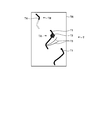
- FIG. 1 is a diagram illustrating an appearance of a shape measuring apparatus 1 according to the first embodiment.
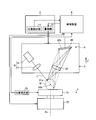
- FIG. 2 is a schematic diagram showing a schematic configuration of the shape measuring apparatus 1 of the present embodiment.
- the optical probe 3 includes a projection device 8 and an imaging device 9 described later. Therefore, it can be said that the relative position between the object to be measured M and the optical probe 3 is the relative position between the object to be measured M and the projection device 8 or the relative position between the object to be measured M and the imaging device 9. Similarly, the relative posture between the object to be measured M and the optical probe 3 may be the relative posture between the object to be measured M and the projection device 8 or the relative posture between the object to be measured M and the imaging device 9. . Further, the device under test M is arranged on the table 71 as described later.
- the first rotating unit 53 and the second rotating unit 54 constitute a moving mechanism that allows the optical probe 3 to rotate, and changes the relative position between the optical probe 3 and the object M to be measured.
- the holding and rotating device 7 constitutes a moving mechanism that allows the object to be measured M held on the table 71 to rotate, and changes the relative position between the optical probe 3 and the object to be measured M.
- the relative posture is changed by rotating the optical probe 3 by the first rotating unit 53 and the second rotating unit 54 and rotating the object to be measured M by the holding rotating device 7.
- the shape measuring apparatus 1 may rotate only the optical probe 3 or the object to be measured M as long as it changes the relative posture.
- the shape measuring apparatus 1 may change the relative posture by rotating at least one of the optical probe 3 and the object M to be measured.
- the rotation axis for rotating the optical probe 3 and the rotation axis for rotating the measurement object M are not limited to the above description. Can be set arbitrarily.
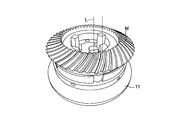
- the longitudinal direction of the linear measurement light L can be changed by the second rotating unit 54 described above. By changing the longitudinal direction of the linear measurement light L according to the spreading direction of the surface of the object to be measured M, the measurement can be performed efficiently.
- the measurement light L irradiated to the measurement object M from the projection device 8 is projected onto the surface of the measurement object M.
- the imaging device 9 as an imaging unit captures an image of the measurement light L projected on the surface of the measurement object M.
- the imaging device 9 includes an imaging element 20 and an imaging optical system 21.
- the illumination light beam that is, the measurement light L irradiated to the measurement object M from the projection device 8 is diffusely reflected on the surface of the measurement object M, and at least a part of the diffuse reflection measurement light L is directed to the imaging optical system 21.
- the imaging optical system 21 connects the image of the measurement light L projected on the surface of the object M to be measured by the projection device 8 to the image sensor 20 by the imaging optical system 21.
- the image sensor 20 outputs an image signal corresponding to the image formed by the imaging optical system 21.
- the measurement region is a region (range) in which the image of the measurement light L is included in the imaging region.
- the shape of the object to be measured M is measured by generating a point cloud from the image of the measurement light L included in this measurement region. That is, the point group is a point on the image for calculating the coordinate value of the photographed image, and the shape of the object to be measured M is measured based on the coordinate value for each point group. Therefore, it can be said that the measurement region is a region (range) used for generating a point cloud.
- the measurement region can be restated as a point group region.
- the measurement area can be referred to as the imaging area.
- the measurement conditions may include a scan start position and a scan end position of the measurement light L irradiated by the optical probe 3.
- the measurement conditions include the relative position between the imaging device 9 (imaging unit) or the projection device 8 (projection unit) and the measurement object M, the relative orientation between the imaging device 9 or the projection device 8 and the measurement object M, and It may be at least one of the intensity of the measurement light L, the exposure and exposure time of the imaging device 9, and the measurement region.
- the condition setting unit 42 sets the measurement condition determined by the teaching of the shape measuring apparatus 1 performed by the operator operating the input unit 32 as the measurement condition, and stores the measurement condition in the storage unit 34.
- the condition setting unit 42 may read the measurement conditions stored in advance in the storage unit 34, set the measurement conditions based on the measurement conditions, or set the measurement conditions by calculation.
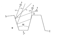
- the shape measuring apparatus 1 detects the image of the measurement light L projected on the location M1 displayed in the captured image, generates a point cloud from the detected image of the measurement light L, and determines the coordinates of the point cloud. By calculating, the shape of the object M to be measured at the location M1 is measured. Furthermore, when measuring the shape of the location M1, the shape measuring device 1 measures the object to be measured so that the diffuse reflected light L1 of the measurement light L projected onto the location M1 enters the imaging device 9. It is required to set measurement conditions such as the relative position and relative attitude between M and the optical probe 3. The reason will be described below.
- the diffuse reflected light L1 is diffusely reflected light in which the measurement light L irradiated from the projection device 8 is reflected only once at the location M1 of the object M to be measured. That is, when the measurement light L emitted from the projection device 8 is applied to the location M1, the reflected light that is diffusely reflected at the location M1 and that reaches the imaging device 9 without being reflected by other locations.
- the diffusely reflected light L1 is diffusely reflected light that is reflected only once at the location M1 and reaches the imaging device 9.
- the dimming conditions such as the intensity of the measurement light L when the imaging device 9 performs imaging are set based on the intensity of the regular reflection light L2, the dimming conditions are set based on the intensity of the diffuse reflection light L1.
- the brightness of the image of the diffuse reflected light L1 may be about 1/1000.
- the image of the measurement light L incident on the imaging device 9 is expressed by a pixel value having only a few hundred gradations, the brightness of the image of the diffuse reflection light L1 becomes too small in the captured image, and the diffuse reflection There is a possibility that the image of the light L1 cannot be detected.
- the image of the regular reflection light L2 is included in the image of the measurement light L captured by the imaging device 9, the image of the diffuse reflection light L1 cannot be detected and the point cloud of the image of the diffuse reflection light L1 is detected. May not be generated properly. Since the image of the diffuse reflected light L1 is an image representing the shape of the object M to be measured at the location M1 in the captured image, if the point cloud of the image of the diffuse reflected light L1 cannot be generated, the shape of the location M1 is measured. It cannot be done properly.
- the light diffusely reflected by the object to be measured M is incident on the other part of the object to be measured M, and the light diffusely reflected by the part may be used as the multiple reflected light L3. Since the position of the multiple reflected light L3 incident on the light receiving surface 20a of the imaging device 9 is different from the diffuse reflected light L1, the image of the multiple reflected light L3 displayed in the captured image is different from the image of the diffuse reflected light L1. Displayed in position. That is, in the captured image, the image of the diffuse reflected light L1 is an image representing the shape of the object M to be measured at the location M1, whereas the image of the multiple reflected light L3 is the image of the object M to be measured M1.
- the luminance of the image can be said to be the intensity of the light that forms the image, and thus the luminance of the image of the diffusely reflected light L1 can be said to be the intensity of the light that forms the image of the diffusely reflected light L1.
- the image of the regular reflection light L2, the image of the multiple reflection light L3, and the case where vignetting occurs are respectively relative to the object to be measured M (location M1). It was explained by changing the position and relative posture.
- the image of the regular reflection light L2, the image of the multiple reflection light L3, the vignetting, and the image In some cases, only one kind of image is captured from the diffuse reflected light L1 image with low intensity of the light, the regular reflected light L2, the multiple reflected light L3 image, the vignetting, There may be a case where two or more types of images are picked up from the diffuse reflected light L1 image having low intensity of the light that forms the image.
- the image of the regular reflection light L2 the image of the multiple reflection light L3, the vignetting, and the diffusion of the light forming the image is low
- the image of the reflected light L1 may be captured all at once.
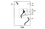
- FIG. 5C is a diagram illustrating an example of a captured image T actually captured by the imaging device 9.
- the captured image T in FIG. 5C is an image showing an image of light captured by the imaging device 9 as described above, and is an image of light in the imaging region TR.
- the diffuse reflected light image T1 is an image of the diffuse reflected light L1 incident on the imaging device 9.
- the regular reflection light image T ⁇ b> 2 is an image of the regular reflection light L ⁇ b> 2 incident on the imaging device 9.
- the multiple reflected light image T3 is an image of the multiple reflected light L3 incident on the imaging device 9.
- FIG. 5C is a diagram illustrating an example of a captured image T actually captured by the imaging device 9.
- the captured image T in FIG. 5C is an image showing an image of light captured by the imaging device 9 as described above, and is an image of light in the imaging region TR.
- the diffuse reflected light image T1 is an image of the diffuse reflected light L1 incident on the imaging device 9.
- the vignetting image T4 is shown in the image TB.
- the vignetting image T4 is an image by vignetting. In other words, it can be said that it is an image of the diffusely reflected light L1 that is partially missing due to vignetting.
- the dotted line portion is a portion lacking due to vignetting, and the dotted line portion is not actually captured.
- the vignetting image T4 is an image of the diffusely reflected light L1 that is partially missing, it is difficult to measure the shape of the missing portion, that is, to detect a point group. Even when the brightness of the diffuse reflection light image T1 is low, the imaging device 9 cannot capture the diffuse reflection light image T1, so that it is difficult to measure the shape using the diffuse reflection light image T1.
- the diffuse reflected light image T1 having a low luminance is referred to as an inappropriate luminance image T5.
- the inappropriate luminance image T5 is, for example, a diffuse reflected light image T1 whose luminance is lower than a predetermined value.
- the predetermined value here may be set by the operator in consideration of the influence of the inappropriate luminance image T5 on the measurement accuracy of the object M to be measured, or calculated based on the design tolerance of the object M to be measured. It may be a value obtained. That is, the regular reflection light image T2, the multiple reflection light image T3, the vignetting image T4, and the inappropriate luminance image T5 may be images inappropriate for shape measurement. Moreover, it can be said that among the reflected light of the measurement light L, an image other than an image that may be an inappropriate image for shape measurement is an image suitable for shape measurement.
- the image suitable for the shape measurement is an image that is not the vignetting image T4 in the diffuse reflected light image T1 (that is, an image that has no missing portions or few missing portions due to vignetting) and has an inappropriate luminance. It can be said that the image is not the image T5.
- the vignetting image T4 is an image of the diffusely reflected light L1 that is partially lost due to vignetting.
- the missing portion (region), that is, the dotted line portion itself, is referred to as the vignetting image T4. You may call it.
- the imaging device 9 may be irradiated with light other than the measurement light L from a light source other than the projection device 8.
- Light irradiated from a light source other than the projection device 8 is also reflected by the object to be measured M, diffusely reflected light (including diffusely reflected light and multiple reflected light reflected only once by the object to be measured M), and specularly reflected light.
- the light is incident on the imaging device 9 and captured by the imaging device 9.
- These diffuse reflection light image and regular reflection light image captured by the imaging device 9 are also unsuitable for shape measurement.
- the light source other than the projection device 8 is the sun or illumination in a factory, and various light sources other than the projection device 8 may be used.
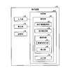
- the analysis unit 40 can easily set measurement conditions that allow the operator to accurately perform shape measurement by executing processing to be described later. To do. Hereinafter, the analysis unit 40 will be specifically described.
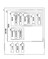
- the analysis unit 40 includes a design information acquisition unit 80, a condition acquisition unit 82, an image analysis unit 83, and an output unit 88.
- the analysis unit 40 uses the image analysis unit 83 to detect an image inappropriate for shape measurement from the image of the measurement light L under the measurement conditions acquired by the condition acquisition unit 82, and based on the detection result by the output unit 88.
- the detection result information is displayed on the display unit 33. The operator can easily set measurement conditions that allow accurate shape measurement by checking the display on the display unit 33.
- the design information acquisition unit 80 acquires design information of the object M to be measured.
- the design information acquisition unit 80 acquires the design information of the device under test M by reading the design information of the device under test M from the storage unit 34.
- the design information of the object M to be measured is information necessary for analysis in the image analysis unit 83 described later.
- the design information of the object M to be measured may be stored in the storage unit 34 in advance, may be acquired by communication during the process, or may be acquired by input of the input unit 32 by the operator.
- the design information includes shape data of the measurement object M and reflectance data of the measurement object M.
- the shape data is data indicating the design shape of the DUT M.
- the shape data is, for example, CAD data, mesh data, point cloud data, and the like.
- the design information acquisition unit 80 may acquire a design value indicating the shape (for example, specification values of the object M to be measured such as a gear or a turbine blade), and obtain shape data by calculation based on the design value.
- the reflectance data is data indicating the design reflectance of the object M to be measured.
- the reflectance data may be data actually measured by a separate measuring machine, or may be a value based on a material or material.
- the object to be measured M may have a plurality of regions having different surface roughnesses or materials, for example, and in this case, the reflectivity is different for each region. In such a case, the reflectance data may be a different value for each of a plurality of regions having different surface roughness and material.
- the condition acquisition unit 82 acquires measurement conditions.
- the condition acquisition unit 82 acquires the determination measurement condition, that is, the measurement condition determined by the teaching of the shape measurement apparatus 1 performed by the operator operating the input unit 32.
- the measurement conditions acquired by the condition acquisition unit 82 are used for analysis by the image analysis unit 83 described later.
- the condition acquisition unit 82 is not limited to acquiring the determined measurement condition as the measurement condition.
- the condition acquisition unit 82 may include information on light other than the measurement light L emitted from a light source other than the projection device 8 in addition to the determination measurement condition as a measurement condition used for the analysis of the image analysis unit 83.
- Information on light other than the measurement light L emitted from a light source other than the projection device 8 is referred to as other light source information.
- the other light source information includes the relative position between the light source other than the projection device 8 and the measurement object M, the relative posture between the light source other than the projection device 8 and the measurement object M, and the intensity of light from the light source other than the projection device 8.
- the other light source information may be input by the operator operating the input unit 32, the other light source information may be stored in the storage unit 34 in advance, or the other light source information may be set by calculation.
- the measurement conditions acquired by the condition acquisition unit 82 other than the other light source information may be, for example, the measurement conditions stored in advance in the storage unit 34, or the measurement conditions set by the condition acquisition unit 82 by calculation. Also good.
- the image analysis unit 83 captures an image that is inappropriate for measuring the shape of the measurement object M when the image of the light projected on the measurement object M is captured based on the design information and measurement conditions of the measurement object M. To detect. In addition, the image analysis unit 83 uses the design information and the measurement conditions of the measurement object M for an image suitable for measuring the shape of the measurement object M when an image of light projected onto the measurement object M is captured. Detect based on. That is, the image analysis unit 83 performs analysis based on the design information of the object to be measured M and the measurement conditions, and detects an image inappropriate for shape measurement and an appropriate image. The image captured by the device 9 is not analyzed.
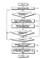
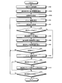
- the image analysis execution unit 84 determines whether or not the intersection of the light beam and the object to be measured M exists by calculating which position of the object to be measured M is irradiated with the light beam.
- the image analysis execution unit 84 can calculate from which direction the light beam is incident according to the measurement conditions, and also knows the shape of the object M to be measured from the design information of the object M to be measured. Whether there is an intersection with the measurement object M can be calculated. That is, the case where there is an intersection between the light beam and the object to be measured M refers to a case where the light beam is irradiated (projected) to a location where the shape of the object to be measured M is measured.
- step S12 When there is no intersection (step S12; No), that is, when the light beam is not irradiated onto the object M, the image analysis execution unit 84 ends the calculation for the light beam and proceeds to step S20 described later.
- the image analysis execution unit 84 calculates the traveling direction of the regular reflected light and the traveling direction of the diffuse reflected light based on the emission angle of the light beam at the intersection.
- the specularly reflected light is a light beam that has been specularly reflected at the intersection point with the measurement object M when the light beam has entered the intersection point with the measurement object M.
- the diffusely reflected light here is a light beam that is diffusely reflected by the light beam incident on the intersection with the object to be measured M at the intersection with the object to be measured M. Then, the image analysis execution unit 84 calculates the intensity of the regular reflection light and the diffuse reflection light based on the reflectance of the measurement object M in the design information.
- step S22 the regular reflection light and the diffuse reflection light incident on the imaging device 9 are extracted from the regular reflection light and the diffuse reflection light whose traveling direction and intensity are calculated in step S22.
- the image analysis execution unit 84 calculates the position of the imaging device 9 from the measurement conditions, and based on the position of the imaging device 9 and the traveling directions of the regular reflection light and the diffuse reflection light calculated in step S16. The regular reflection light and diffuse reflection light incident on the light are extracted. Then, the image analysis execution unit 84 calculates the incident position (coordinates) on the light receiving surface 20a for each of the regular reflection light and diffuse reflection light incident on the imaging device 9, and calculates analysis result data (step). S24).
- the detection unit 86 evaluates the diffuse reflected light image P1 that has been detected as an appropriate image, thereby determining whether the diffuse reflected light image P1 includes the vignetting image P4 and the inappropriate luminance image P5.
- evaluation determination
- the vignetting image P4 and the inappropriate luminance image P5 are evaluated (determined) as being inappropriate images.
- U1 is the intensity of the light that formed the specularly reflected light image P2, more specifically, the intensity of the light of the specularly reflected light L2 that is reflected at the intersection and incident on the imaging device 9 in the analysis of the image analysis execution unit 84.
- D1 is a position (coordinates) of the light beam 20a on the light receiving surface 20a of the regular reflection light L2 reflected at the intersection and incident on the imaging device 9, and the light beam of the diffuse reflection light L1 reflected on the intersection and incident on the imaging device 9. The distance from the position (coordinates) on the light receiving surface 20a.
- the detection unit 86 calculates a diffuse reflection light image P1 in the measurement area PL used for measurement in the calculation of D1 (a diffuse reflection light image PA in FIG. 8 described later). It is preferable to calculate the distance between the light beam of the diffusely reflected light L1 and the regular reflected light image P2.
- D2 is the position of the light beam of the multiple reflected light L3 that is reflected at the intersection and incident on the imaging device 9 on the light receiving surface 20a, and the diffuse reflected light L1 that is reflected at the intersection and incident on the measurement region PL.
- the distance between the light beam and the position on the light receiving surface 20a may include the image in the calculation of the influence level V2.
- the detection unit 86 calculates an influence level V3 of the brightness of the detected diffuse reflected light image P1 (the intensity of the light that formed the diffuse reflected light image P1) (step S36), thereby causing inappropriate brightness as described later. It is evaluated whether the image P5 exists.
- the diffuse reflection light image P1 is also formed by collecting a plurality of images formed by the light of the diffuse reflection light L1 that is reflected at the intersection and incident on the imaging device 9. In this case, as shown in the following equation (3), the detection unit 86 sums up the intensities of the light beams of the diffuse reflected light L1 reflected at the intersection and incident on the imaging device 9, and the brightness of the diffuse reflected light image P1.
- U3 is the intensity of one light beam of the diffuse reflected light L1 reflected at the intersection and incident on the imaging device 9, and is reflected by one light beam of the diffuse reflected light L1 reflected at the intersection and incident on the imaging device 9. It can also be said that it is the brightness of the diffuse reflection light image P1 to be formed.
- the detection unit 86 reflects the intensity of light that forms the image of the diffuse reflection light L1 in the measurement region PL, that is, the diffuse reflection that is reflected at the intersection and enters the measurement region PL. It is preferable to calculate the influence V3 by summing up the intensities of the light rays of the light L1.
- the detection unit 86 evaluates whether or not the vignetting image P4 exists as will be described later by calculating the influence V4 of the area of the diffuse reflected light image P1 (step S38). As shown in the following equation (4), the detection unit 86 calculates a measurement range that is an area occupied by the diffuse reflected light image P1 in the imaging region PL, and sets the calculated measurement range as an influence level V4. .
- R1 is the area of the imaging region PL
- R2 is the area of the diffuse reflected light image P1 in the imaging region PL.
- the vignetting image P4 is a diffusely reflected light image P1 that is partially missing.
- the value of influence degree V0 changes by changing the measurement conditions. For example, if the intensity of the measurement light L is increased as the measurement condition with respect to the determined measurement condition, the intensity of the regular reflection light L2 becomes higher than the intensity of the regular reflection light L2 under the determined measurement condition. The degree of influence V1 becomes larger than the measured condition. Therefore, the detection unit 86 calculates the influence level V1 when the intensity of the measurement light L is increased, for example, and the influence level V1 increases, so that the luminance of the image of the diffuse reflected light L1 becomes too small and diffuses. It can be evaluated that there is a high possibility that the reflected light image P1 cannot be detected and the shape measurement cannot be appropriately performed.
- the detection unit 86 When detecting the vignetting image P4, the detection unit 86 performs detection based on the analysis result data. When detecting the vignetting image P4, the detection unit 86 calculates, as the number of incident light beams, the number of light beams of the diffusely reflected light L1 that is extracted at step S22 in FIG. . Then, the detection unit 86 calculates a value obtained by dividing the number of incident light rays by the total number of light rays divided in step S10 in FIG. 6 as an incidence ratio value. This incident ratio value can be said to be a value indicating the ratio of the light incident on the imaging device 9 as diffuse reflected light in the measurement light L.
- the detection unit 86 determines in advance the intensity of the diffusely reflected light L1 reflected at the intersection and incident on the imaging device 9, that is, U3 in Expression (3). You may detect whether it is more than predetermined intensity. Then, the detection unit 86 reflects an image of which the intensity of the light beam is greater than or equal to a predetermined intensity among the images formed by the light beam of the diffuse reflection light L1 that is reflected at the intersection and incident on the imaging device 9, and the diffuse reflection light image P1, That is, an image is detected as an appropriate image, and an image whose light intensity is smaller than a predetermined intensity is detected as an inappropriate luminance image P5, that is, an inappropriate image.
- the detection unit 86 detects the inappropriate luminance image P5 when the luminance of the diffuse reflected light image P1 is small. In other words, the detection unit 86 detects the inappropriate luminance image P5 when the luminance of the diffuse reflected light image P1 is low, in other words, when the intensity of the light beam of the diffuse reflected light L1 is small.
- the light intensity of the diffusely reflected light L1 is also reflected by, for example, the light of the diffusely reflected light L1 re-reflected in the imaging optical system 21 (lens) of the imaging device 9 and imaged as a flare. The shape measurement may not be performed properly.
- the detection part 86 detects the inappropriate image at the time of setting it as another measurement condition using the analysis result data of another measurement condition. And the detection part 86 evaluates an inappropriate image based on the detection result of the inappropriate image in another measurement condition. That is, the detection unit 86 calculates the degree of influence V0 for the inappropriate image and the appropriate image detected under different measurement conditions by the same method as the evaluation under the acquisition measurement condition.
- the detection unit 86 detects how the influence degree V0 under the different measurement conditions changes from the influence degree V0 under the acquisition measurement conditions. That is, the detection unit 86 calculates how the influence level V0 under the different measurement conditions changes with respect to the influence level V0 under the acquired measurement conditions.
- the detection unit 86 determines that the influence degree V1 is increased when the measurement condition is changed to another measurement condition when the influence degree V1 in the different measurement condition is larger than the influence degree V1 in the acquired measurement condition. For example, when the influence level V1 under the acquisition measurement condition is smaller than the threshold value (when the regular reflection light image P2 is not an inappropriate image), the influence degree V1 under another measurement condition is the influence degree V1 under the acquisition measurement condition. If it becomes larger, it can be said that the other measurement condition is a measurement condition that increases the possibility that the specularly reflected light image P2 is an inappropriate image.
- the degree of influence V1 under the acquisition measurement condition is equal to or greater than the threshold value (when the regular reflection light image P2 is an inappropriate image)
- the degree of influence V1 under another measurement condition is greater than the degree of influence V1 under the acquisition measurement condition.
- the separate measurement condition is a measurement condition that reduces the possibility that the specularly reflected light image P2 is an appropriate image. That is, when the influence level V1 under another measurement condition is larger than the influence degree V1 under the acquisition measurement condition, the possibility that the specularly reflected light image P2 becomes an improper image is high, It can be said that the possibility that the reflected light image P2 is an appropriate image is low.
- the detection unit 86 determines that the influence degree V2 is reduced when the measurement condition is changed to another measurement condition. For example, when the influence level V2 under the acquisition measurement condition is smaller than the threshold value (when the multiple reflected light image P3 is not an inappropriate image), the influence degree V2 under another measurement condition is the influence degree V2 under the acquisition measurement condition. If it becomes smaller, the influence V2 becomes smaller with respect to the threshold value under the separate measurement condition, and the separate measurement condition is a measurement condition that further reduces the possibility that the multiple reflected light image P3 is an inappropriate image. It can be said.
- the influence degree V2 under another measurement condition is smaller than the influence degree V2 under the acquisition measurement condition.
- the separate measurement condition is a measurement condition that increases the possibility that the multiple reflected light image P3 is an appropriate image. That is, when the influence V2 under the different measurement conditions is smaller than the influence V2 under the acquisition measurement conditions, the separate measurement conditions may reduce the possibility that the multiple reflected light image P3 will be an inappropriate image or multiple It can be said that there is a high possibility that the reflected light image P3 is an appropriate image.
- the detection unit 86 determines that the influence degree V3 increases when the measurement condition is changed to another measurement condition when the influence degree V3 under the different measurement condition is larger than the influence degree V3 under the acquired measurement condition. For example, when the influence level V3 under the acquisition measurement condition is smaller than the threshold value (when the inappropriate luminance image P5 is an inappropriate image), the influence degree V3 under another measurement condition is the influence degree V3 under the acquisition measurement condition. When it becomes larger, it can be said that the other measurement condition is a measurement condition that increases the possibility that the inappropriate luminance image P5 is an appropriate image (that is, it is evaluated that there is no inappropriate luminance image P5).
- the separate measurement condition is likely to cause the inappropriate luminance image P5 to be an appropriate image or inappropriate. It can be said that the possibility that the luminance image P5 is an inappropriate image is low.
- the detection unit 86 determines that the influence degree V3 becomes smaller when the measurement condition is changed to another measurement condition when the influence degree V3 under the different measurement condition is smaller than the influence degree V3 under the acquired measurement condition. For example, when the influence level V3 under the acquisition measurement condition is smaller than the threshold value (when the inappropriate luminance image P5 is an inappropriate image), the influence degree V3 under another measurement condition is the influence degree V3 under the acquisition measurement condition. If it becomes smaller, the influence level V3 is further reduced with respect to the threshold value under the separate measurement condition. Therefore, the inappropriate brightness image P5 is regarded as an appropriate image (that is, it is evaluated that there is no inappropriate brightness image P5). It can be said that this is a measurement condition with a lower possibility.
- the degree of influence under another measurement condition When V3 becomes smaller than the influence level V3 in the acquisition measurement condition, another measurement condition is a measurement in which there is a high possibility that there is an inappropriate luminance image P5 (the inappropriate luminance image P5 is regarded as an inappropriate image). It can be said that it is a condition. That is, when the influence level V3 under another measurement condition is smaller than the influence degree V3 under the acquisition measurement condition, the possibility that the inappropriate luminance image P5 is an appropriate image is low or inappropriate. It can be said that there is a high possibility that the luminance image P5 is an inappropriate image.
- the detection unit 86 determines that the influence degree V4 is increased when the measurement condition is changed to another measurement condition when the influence degree V4 under the different measurement condition is larger than the influence degree V4 under the acquired measurement condition. For example, when the influence level V4 under the acquisition measurement condition is smaller than the threshold value (when the vignetting image P4 is an inappropriate image), the influence degree V4 under another measurement condition is greater than the influence level V4 under the acquisition measurement condition. Then, it can be said that the other measurement conditions are measurement conditions that increase the possibility that the vignetting image P4 is an appropriate image (that is, it is evaluated that there is no vignetting image P4).
- the influence level V4 under the acquisition measurement condition is equal to or greater than the threshold value (when the vignetting image P4 is not an inappropriate image and is evaluated as having no vignetting image P4)
- the influence level V4 under another measurement condition is acquired and measured.
- the influence level V4 exceeds the condition, the influence level V4 is further increased with respect to the threshold value in the separate measurement condition. Therefore, the separate measurement condition includes the vignetting image P4 (the vignetting image P4 is an inappropriate image).
- this is a measurement condition that further reduces the possibility of That is, when the influence level V4 under the different measurement conditions is larger than the influence level V4 under the acquired measurement conditions, the possibility of the vignetting image P4 being an appropriate image is high or the vignetting image P4 It can be said that the possibility of being inappropriate is low.
- the detection unit 86 determines that the influence degree V4 becomes smaller when the measurement condition is changed to another measurement condition when the influence degree V4 under the different measurement condition is smaller than the influence degree V4 under the acquired measurement condition. For example, when the influence level V4 under the acquisition measurement condition is smaller than the threshold value (when the vignetting image P4 is an inappropriate image), the influence degree V4 under another measurement condition is smaller than the influence level V4 under the acquisition measurement condition. In this case, the influence V4 is further smaller than the threshold value under the separate measurement condition, and it is unlikely that the vignetting image P4 is an appropriate image (that is, it is evaluated that there is no vignetting image P4). It can be said that the measurement conditions are as follows.
- the influence level V4 under the acquisition measurement condition is equal to or greater than the threshold (when the vignetting image P4 is not an inappropriate image and it is evaluated that there is no vignetting image P4)
- the influence level V4 under another measurement condition is acquired and measured.
- the other measurement condition is a measurement condition that increases the possibility that the vignetting image P4 is present (the vignetting image P4 is an inappropriate image). That is, when the influence level V4 under the different measurement conditions is smaller than the influence level V4 under the acquired measurement conditions, the possibility of the vignetting image P4 being an appropriate image is low, or the vignetting image P4 is low. It can be said that the possibility of being considered inappropriate is high.
- the detection unit 86 calculates how the influence degree V0 when the measurement condition is changed changes. Since the evaluation result of the detection unit 86 in this embodiment evaluates an inappropriate image and an appropriate image based on a comparison between the influence level V0 and a threshold value, the detection unit 86 changes how the influence level V0 changes. By calculating this, it can also be said that the change in the evaluation result of the detection unit 86 is calculated. That is, as described above, for example, when the influence level V4 increases, the evaluation result of the detection unit 86 is less likely to cause the vignetting image P4 to be an appropriate image, or the vignetting image P4 may be an inappropriate image. It changes as if the sex becomes higher.
- change information information on the change in the influence degree V0 detected by the detection unit 86 when the measurement condition is changed is referred to as change information.
- the change information can also be referred to as change information of the evaluation result when the measurement condition is changed.
- the output unit 88 causes the display unit 33 to display an image by outputting detection result information, which is information based on the detection result of the image analysis unit 83, to the display unit 33.
- detection result information which is information based on the detection result of the image analysis unit 83.
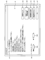
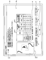
- FIG. 9A is a diagram showing an example of the menu image A.
- the output unit 88 outputs information for displaying the menu image A on the display unit 33 and causes the display unit 33 to display the menu image A when the operator sets measurement conditions for shape measurement.
- the menu image A displayed by the display unit 33 includes an instruction image A1, a scan margin setting image A2, measurement check images A3 and A4, an initial condition image A5, a verification scan image A6, and an OK image A7. .
- the analysis unit 40 performs a measurement check.
- the measurement control unit 38 performs the verification scan.
- the measurement check refers to an analysis by the image analysis unit 83.
- the image analysis execution unit 84 analyzes based on the design information acquired by the design information acquisition unit 80 and the measurement conditions acquired by the condition acquisition unit 82.
- the result data is calculated
- the detection unit 86 refers to a process of deriving a detection result by detecting an inappropriate image and an appropriate image and deriving an evaluation result by performing an evaluation based on the detection result.
- the measurement condition acquired by the condition acquisition unit 82 that is, the measurement condition for performing the analysis is the measurement condition (determined measurement condition) determined by teaching by the operator.
- the verification scan is a measurement condition (determined measurement condition) determined by teaching by the operator.
- the measurement light L from the projection device 8 is projected onto the measurement object M, and the measurement light L projected onto the measurement object M is measured.
- This refers to processing for generating a point cloud from a captured image T captured by the imaging device 9 and captured by the imaging device 9.
- each image of the menu image A will be described.
- the instruction image A1 is an image on which contents for notifying an operation to be performed by the operator in the future are displayed.
- the instruction image A1 includes information “Teaching is performed.” This is information for allowing the operator to recognize that teaching is performed.
- the instruction image A1 includes information that “please perform measurement check when setting is completed”, and is information for allowing the operator to recognize that the measurement check is performed when the measurement condition is set.
- the instruction image A1 includes information that “please check the actual point cloud by performing a verification scan”, and after the measurement check is completed, the verification scan is performed and the generated point cloud This is information for urging to confirm whether there is no problem.
- the instruction image A1 includes information “Please press OK when completed”. This completes the determination of the measurement condition and completes the verification scan. If there is no problem, the actual image is OK. This information prompts to start shape measurement.
- the menu image A may not include the instruction image A1.
- FIG. 9B is a diagram for explaining the scan margin.
- the scan margin setting image A2 is an image that can be selected by the input unit 32 by the operation of the input unit 32 by the operator, and is an image that allows the operator to determine the scan margin.
- the scan margin is the scan start position SC1 and the scan end position SC4 of the measurement light L, that is, the position where the scan of the measurement light L starts and the position where the scan ends. This is the margin for the measurement position. That is, when measuring, the measurement light L is moved (scanned) on the locus from the scan start position SC1 to the scan end position SC4. However, the object to be measured M actually exists between the measurement start position SC2 and the measurement end position SC3.
- the scan margin is a value indicating how far the scan start position SC1 is on the upstream side of the trajectory with respect to the measurement start position SC2, and how much the scan end position SC4 is on the downstream side of the trajectory with respect to the measurement end position SC3. It is.
- the scan margin setting image A2 has a start setting image A2a and an end setting image A2b.
- the input unit 32 includes a mouse and a keyboard
- the operator operates the mouse of the input unit 32 to place the mouse cursor on the screen of the display unit 33, that is, on the menu image A, and to set the scan margin setting image. It is superimposed on the start setting image A2a or the end setting image A2b of A2.
- the start setting image A2a is an image in which it is possible to set the percentage of the scan margin at the scan start position SC1, that is, how much the scan start position SC1 is set before the measurement start position SC2.
- the end setting image A2b is an image for setting the percentage of the scan margin at the scan end position SC4, that is, how much the scan end position SC4 is behind the measurement end position SC3.
- the operator clicks a mouse button with the cursor superimposed on the start setting image A2a, and operates a keyboard included in the input unit 32 to input, for example, a numerical value, and a scan start position.
- the scan margin at SC4 can be set.
- the display unit 33 is a touch panel
- the operator touches the position where the start setting image A2a or the end setting image A2b on the display screen of the display unit 33 is displayed, so that the start setting image A2a or the end setting image is displayed.
- the scan margin may be set by selecting A2b and touching the operation panel displayed on the display screen of the display unit 33 to input a numerical value.
- the menu image A may not include the scan margin setting image A2.
- the operator touches the position where the measurement check image A3 or the measurement check image A4 is displayed on the display screen of the display unit 33, so that the measurement check image A3 or the measurement check image is displayed.
- Select A4 Note that, as an example, the measurement check image A3 is a display for executing an analysis under the measurement condition of scanning one tooth at a time as shown in FIG. 9B.
- the measurement check image A4 is a display for executing an analysis under the condition that the object to be measured M is rotated and all teeth are scanned to measure at high speed.
- the menu image A only needs to include at least one of the measurement check images A3 and A4.
- the initial condition image A5 is a display for returning the measurement conditions to the initial settings.
- the input unit 32 includes a mouse
- the operator operates the mouse of the input unit 32 to superimpose the mouse cursor on the initial condition image A5 on the screen of the display unit 33.
- the operator selects the initial condition image A5 by clicking the mouse button while the cursor is superimposed on the initial condition image A5.
- the display unit 33 is a touch panel
- the operator selects the initial condition image A5 by touching the position where the initial condition image A5 is displayed on the display screen of the display unit 33.
- the measurement condition returns to the initially set measurement condition (initial condition).
- the verification scan image A6 is a display for performing a verification scan.
- the input unit 32 includes a mouse
- the operator operates the input unit 32 to superimpose the mouse cursor on the verification scan image A6 on the screen of the display unit 33.
- the operator selects the verification scan image A6 by clicking the mouse button while the cursor is superimposed on the verification scan image A6.
- the display unit 33 is a touch panel
- the operator selects the verification scan image A6 by touching the position where the verification scan image A6 is displayed on the display screen of the display unit 33.
- the measurement control unit 38 executes the verification scan under the determined measurement conditions.
- the measurement control unit 38 causes the projection device 8 to project the measurement light L onto the measurement object M, and causes the imaging device 9 to capture an image of the measurement light L projected onto the measurement object M. And the measurement control part 38 produces
- OK image A7 is a display for ending teaching and moving to actual measurement.
- the input unit 32 includes a mouse
- the operator operates the input unit 32 to superimpose the mouse cursor on the OK image A7 on the screen of the display unit 33.
- the operator selects the OK image A7 by clicking the mouse button while the cursor is superimposed on the OK image A7.
- the display unit 33 is a touch panel
- the operator selects the OK image A7 by touching the position where the OK image A7 is displayed on the display screen of the display unit 33.
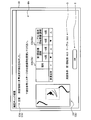
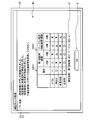
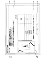
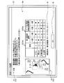
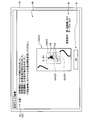
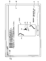
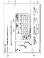
- FIG. 10 and 11 are diagrams illustrating an example of the measurement check result screen B.
- FIG. As described above, for example, the operator operates the mouse of the input unit 32 to click the measurement check images A3 and A4 by clicking the mouse button in a state where the cursor is superimposed on the measurement check images A3 and A4. select.
- the image analysis unit 83 starts the measurement check when the measurement check images A3 and A4 are selected in this way. That is, in the image analysis unit 83, the image analysis execution unit 84 performs analysis and generates analysis result data.
- the detection unit 86 detects an inappropriate image and an appropriate image based on the analysis result data, and evaluates the inappropriate image and the appropriate image based on the detection result.
- the output unit 88 outputs detection result information to the display unit 33 to display the measurement check result screen B shown in FIG.
- the detection result information is information based on the detection result of the detection unit 86.
- the measurement check result screen B displayed by the display unit 33 is a screen for displaying an image (detection result image C described later) indicating detection result information.
- the operator visually recognizes that there is an inappropriate image or an appropriate image under the measurement conditions in the measurement check by checking the detection result image C on the measurement check result screen B. be able to.
- the operator confirms the contents of the detection result image C, and adjusts the measurement conditions again, for example, when there is an inappropriate image.
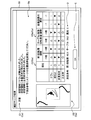
- FIG. 10 shows an example of a measurement check result screen B when an inappropriate image is detected.
- FIG. 10 shows an example in which a specularly reflected light image P2, a multiple reflected light image P3, and a vignetting image P4 are detected as inappropriate images.
- the measurement check result screen B displays a detection result image C, a measurement condition image D, and an OK image E.
- the detection result image C is an image that displays the contents of detection result information based on the detection result of the detection unit 86, in other words, an image that displays information on an inappropriate image detected by the detection unit 86.
- the output unit 88 displays the detection result image C on the display unit 33 by outputting the detection result information to the display unit 33.
- the detection result information is information based on the detection result of the detection unit 86.
- the detection result of the detection unit 86 includes the detected diffuse reflection light image P1 (detected appropriate image), the detected regular reflection light image P2 and the multiple reflection light image P3 (detected inappropriate image). Point to.
- the detection result information includes the evaluation result of the detection unit 86 as information based on the detection result.
- the evaluation result is information indicating evaluation (determination) that the image is inappropriate or appropriate, in other words, information indicating whether there is an image evaluated as inappropriate and appropriate It can be said that it is information on whether there is an image and an evaluated image.
- the evaluation result also includes information indicating what kind of inappropriate image has been evaluated, that is, the type of image that has been determined to be inappropriate by the evaluation. Therefore, the information indicating the type of the image determined to be an inappropriate image by the evaluation is that the image evaluated as the inappropriate image is the specular reflection light image P2, the multiple reflection light image P3, the vignetting image P4, and the inappropriate luminance image.
- the evaluation result includes information indicating whether or not the specular reflection light image P2 is evaluated, information indicating whether or not the multiple reflection light image P3 is evaluated, and the vignetting image P4. It has information indicating whether or not it has been evaluated, and information indicating whether or not there is an inappropriate luminance image P5.
- the evaluation result also includes information indicating whether or not an inappropriate image is not evaluated, that is, whether or not an inappropriate image is evaluated (only an appropriate image is present).
- the detection result information includes change information indicating a change in the degree of influence V0 when the measurement condition is changed.
- the detection result information also includes image data for displaying the redevelopment C0 on the display unit 33, that is, information based on analysis result data for each position on the light receiving surface 20a.
- the image data for displaying the redevelopment C0 on the display unit 33 is image data of an inappropriate image evaluated as an inappropriate image by the detection unit 86 and an appropriate image for the detection unit 86. And image data of an appropriate image evaluated. Therefore, the redevelopment C0 displayed by the image data is the redevelopment C0 including the inappropriate image and the appropriate image.
- the re-development C0 can be said to be information based on the evaluation result including the evaluated inappropriate image and the evaluated appropriate image.
- the image data for displaying the redevelopment C0 on the display unit 33 may be image data of an inappropriate image detected by the detection unit 86 and image data of an appropriate image detected by the detection unit 86. Good.
- the re-development C0 may be information based on the detection result including the detected inappropriate image and the detected appropriate image.
- the detection result information may include a detection result.
- the detection result included in the detection result information is information indicating the inappropriate image detected by the detection unit 86 and the detected appropriate image.
- the detection results included in the detection result information can be said to be information on whether there is an inappropriate image and a detected image and information on whether there is an appropriate image and a detected image.
- the detection result included in the detection result information includes information indicating what kind of inappropriate image is detected, that is, information indicating the type of image determined to be an inappropriate image by detection.
- the information indicating the type of image determined to be an inappropriate image by detection is information indicating whether the image detected as an inappropriate image is the regular reflection light image P2 or the multiple reflection light image P3. It can be said.
- the detection result included in the detection result information includes information indicating whether or not the regular reflection light image P2 is detected and information indicating whether or not the multiple reflection light image P3 is detected. .
- the detection result included in the detection result information also includes information indicating that an inappropriate image is not detected, that is, whether an inappropriate image is detected.
- the above-described evaluation result is information that evaluates whether there is an inappropriate image and an appropriate image, and there is a possibility of overlapping with this detection result. Therefore, when the evaluation result is included in the detection result information, the detection result may not be included in the detection result information. Conversely, when the detection result includes the detection result, the evaluation result does not need to be included in the detection result information. That is, the detection result information only needs to include at least one of the evaluation result and the detection result. In the following description, it is assumed that the detection result information includes the evaluation result and does not include the detection result.
- the detection result image C displayed by the display unit 33 based on the detection result information includes a redevelopment C0, a detection result notification image C1, an evaluation result image C2, and a change image C3.
- the output unit 88 outputs image data for displaying the redevelopment C0 on the display unit 33 to the display unit 33 as detection result information, and causes the display unit 33 to display the redevelopment C0.
- the redevelopment C0 in FIG. 10 includes a regular reflection light image P2, a multiple reflection light image P3, and a vignetting image P4 as inappropriate images.
- the redevelopment C0 is displayed adjacent to the evaluation result image C2 and the change image C3, but the display position is arbitrary.
- the output unit 88 outputs the evaluation result as detection result information to the display unit 33, and causes the display unit 33 to display the detection result notification image C1.
- the detection result notification image C1 is an image indicating the presence or absence of an inappropriate image.
- the image data for displaying the redevelopment C0 is also information indicating the presence or absence of an inappropriate image. Therefore, it can be said that the re-development C0 and the evaluation result image C2 described later are images indicating information on the presence or absence of inappropriate images. Therefore, in other words, it can be said that the detection result image C is an image indicating information on the presence or absence of an inappropriate image.
- the output unit 88 When the output unit 88 is evaluated as having an inappropriate image, as an evaluation result, information indicating that there is an image that has been evaluated as an inappropriate image and what inappropriate image has been evaluated. , That is, information on the evaluated inappropriate image type is output to the display unit 33.
- the detection result notification image C1 indicates that the type of inappropriate image is the vignetting image P4 and “the vignetting image P4 has been evaluated as an inappropriate image.
- the detection result notification image C1 also includes information that prompts the user to adjust the measurement conditions, such as “Please change the position and orientation of the stage with reference to the table below”.
- the detection result notification image C1 is not limited to the display using the above-described character example, and may be a display using another character string.
- the display is not limited to characters, and information indicating that an inappropriate image has been detected and information on the type of the detected inappropriate image may be displayed using, for example, a picture or a symbol.
- the detection result notification image C1 may display only information indicating the presence or absence of an inappropriate image. As shown in FIG. 10, the detection result image C is displayed in the upper area of the measurement check result screen B, but the display position is arbitrary.
- the output unit 88 outputs the evaluation result to the display unit 33 as detection result information, and causes the display unit 33 to display the evaluation result image C2.
- the evaluation result image C2 is an image indicating the evaluation result of the inappropriate image.
- the evaluation result for displaying the evaluation result image C2 is information including evaluation by the detection unit 86 for each image evaluated as an inappropriate image.
- the vignetting image P4, the regular reflection light image P2, and the multiple reflection light image P3 are evaluated as inappropriate images, and the inappropriate luminance image P5 is not evaluated as an inappropriate image. That is, it is evaluated that there is no inappropriate luminance image P5. Therefore, in the example of FIG.
- the evaluation result for displaying the evaluation result image C2 includes information indicating that the vignetting image P4, the regular reflection light image P2, and the multiple reflection light image P3 are evaluated as inappropriate images
- the inappropriate luminance image P5 includes information indicating that it is not evaluated as an inappropriate image (there is no inappropriate luminance image P5).
- the evaluation result image C2 includes the vignetting image P4 (“vignetting” in FIG. 10), the inappropriate luminance image P5 (“brightness” in FIG. 10), and the specular reflected light image P2 (FIG. 10). 10, “regular reflection”) and the multiple reflected light image P ⁇ b> 3 (“multiple reflection” in FIG. 10) are displayed as images.
- the vignetting image P4, the specular reflection light image P2, and the multiple reflection light image P3 are inappropriate images in the evaluation by the detection unit 86, and therefore, x is displayed.
- the inappropriate luminance image P5 is not indicated as an inappropriate image in the evaluation by the detection unit 86, and is displayed as “ ⁇ ” because there is no problem.
- the types of images evaluated as inappropriate images are displayed in the first column, and the images evaluated as inappropriate images displayed in the first column are displayed in the second column. It is a table on which the evaluation results (here, ⁇ or ⁇ ) are displayed.
- the evaluation result image C2 is an image indicating the evaluation by the detection unit 86 for each image evaluated as an inappropriate image
- the display method is not limited to the form of the table as shown in FIG. is there.
- the evaluation result image C2 is not limited to symbols such as ⁇ and X, but may be other symbols as long as the evaluation result by the detection unit 86 can be notified to the operator. Moreover, not only a symbol but a character string may be sufficient. In this case, for example, “OK” may be displayed if it is not evaluated as an inappropriate image, and “NG” may be displayed if it is evaluated as an inappropriate image. Further, the evaluation result image C2 may be a color display. In this case, for example, if it is not evaluated as an inappropriate image, green is displayed on the target portion of the evaluation result image C2, and if it is evaluated as an inappropriate image, red is displayed on the target portion of the evaluation result image C2. Display may be performed.
- the evaluation result is not limited to being notified to the operator by visual information as the evaluation result image C2.
- the evaluation result may be audio information that informs the operator of the presence or absence of the evaluated inappropriate image by voice. In this case, for example, sound is output to the operator through a speaker (not shown).
- the output unit 88 outputs the change information as detection result information to the display unit 33 and causes the display unit 33 to display the change image C3.
- the change image C3 is an image indicating change information.
- the change information is information on a change in the degree of influence V0 when the measurement condition is changed. More specifically, the change information for displaying the change image C3 includes the influence degree V0 of the image evaluated as an inappropriate image when the value of the measurement condition of the apparatus included in the shape measuring apparatus 1 is changed. The information indicates the tendency of change.
- the apparatus included in the shape measuring apparatus 1 includes a first rotating part 53, a second rotating part 54, and a table 71 (holding rotating apparatus 7) that change the relative posture, and an X moving part 50X and a Y moving that change the relative position.
- the change information includes information on how the degree of influence V0 changes when the angle of the first rotating unit 53 is changed, and how the degree of influence V0 changes when the angle of the table 71 is changed. Information about whether the image changes is included for each image evaluated as inappropriate. In addition, change information is good also as an apparatus which the shape measuring apparatus 1 has apparatuses other than the 1st rotation part 53 and the table 71.
- the change image C3 includes a case where the angle of the first rotation unit 53 is changed by +5 degrees and a case where the angle of the first rotation unit 53 is changed by -5 degrees from the current measurement conditions.
- the change tendency of each degree of influence V0 when the table 71 is changed by +5 degrees and when the table 71 is changed by -5 degrees is shown.
- the information indicating the change tendency of the influence level V4 is that the influence level V4 for the vignetting image P4 (“vignetting” in FIG. 10) is +5 degrees for the first rotation unit 53.
- the change image C3 displays a symbol indicating the upward direction as information indicating the tendency of the change in the degree of influence V4. Further, the degree of influence V4 on the vignetting image P4 becomes small when the first rotating portion 53 is changed by -5 degrees and when the table 71 is changed by -5 degrees, that is, the vignetting image P4 is appropriate. The possibility of being an image is low. Therefore, the change image C3 displays a symbol indicating the downward direction as information indicating the tendency of the change in the influence degree V4.
- the information indicating the change tendency of the influence level V3 includes the case where the influence level V3 for the inappropriate luminance image P5 (“brightness” in FIG. 10) changes the first rotating unit 53 by ⁇ 5 degrees.
- the change image C3 displays a symbol indicating an upward direction as information indicating a change tendency of the influence degree V3.
- the influence level V3 for the inappropriate luminance image P5 becomes small when the first rotating unit 53 is changed by +5 degrees and when the table 71 is changed by -5 degrees, that is, the inappropriate luminance image. P5 is likely to be an inappropriate image. Therefore, the change image C3 displays a symbol indicating a downward direction as information indicating a tendency of change in the influence degree V3.
- the information indicating the tendency of the change in the influence degree V2 includes the case where the influence degree V2 for the multiple reflected light image P3 (“multiple reflection” in FIG. 10) changes the first rotating unit 53 by ⁇ 5 degrees.
- the table 71 becomes smaller, that is, the possibility that the multiple reflected light image P3 becomes an appropriate image is increased. Therefore, the change image C3 displays a symbol indicating the upward direction as information indicating the tendency of change in the influence degree V2.
- the influence V2 on the multiple reflected light image P3 increases when the first rotating unit 53 is changed by +5 degrees and when the table 71 is changed by +5 degrees, that is, the multiple reflected light image P3. Is even less likely to be an appropriate image. Therefore, the change image C3 displays a symbol indicating a downward direction as information indicating a tendency of change in the influence degree V2.
- the information indicating the change tendency of the influence degree V1 includes the case where the influence degree V1 of the regular reflection light image P2 (“regular reflection” in FIG. 10) changes the first rotating unit 53 by +5 degrees,
- the influence V1 is low both when the first rotating unit 53 is changed by -5 degrees, when the table 71 is changed by +5 degrees, and when the table 71 is changed by -5 degrees. Therefore, the possibility that the regular reflection light image P2 is an appropriate image is high.
- the influence degree V1 is zero.
- the detection unit 86 determines that the regular reflection light image P2 is an appropriate image. Therefore, the change image C3 shown in FIG. 10 displays ⁇ as information indicating the tendency of change in the influence degree V1. Further, the change image C3 has zero influence V1 under the current measurement conditions (determined as an appropriate image), and when the measurement condition is changed, the influence V1 becomes high. Good. However, the change image C3 may display a symbol indicating an upward direction when the influence level V1 is greater than zero under the current measurement condition and the value of the influence degree V1 becomes zero when the measurement condition is changed.
- the change image C3 may display a symbol indicating a downward direction when the influence level V1 is zero under the current measurement condition and the value of the influence degree V1 increases when the measurement condition is changed. Further, the change image C3 may display a symbol indicating a downward direction when the influence level V1 is larger than zero under the current measurement condition and the value of the influence degree V1 does not change when the measurement condition is changed.
- the change image C3 is displayed in the same table as the evaluation result image C2. That is, in the example of FIG. 10, as described above, the types of images evaluated as inappropriate images are displayed in the first column of the table, and the inappropriate images displayed in the first column are displayed in the second column. The evaluation of the image to be evaluated is displayed. Then, the change image C3 displays information indicating the change tendency of each influence V0 when the first rotation unit 53 is changed by +5 degrees in the third column of the table, and in the fourth column of the table, Information indicating the tendency of change in each degree of influence V0 when the first rotating unit 53 is changed by -5 degrees is displayed, and each influence when the table 71 is changed by +5 degrees is displayed in the fifth column of the table.
- the result of the change image C3 illustrated in FIG. 10 is an example.
- the change image C3 is the same table as the evaluation result image C2, and is displayed at the center of the measurement check result screen B (below the detection result notification image C1).
- the display method and the display position of the evaluation result image C2 and the change image C3 are not limited thereto and are arbitrary.
- the evaluation result image C2 and the change image C3 may be in different tables.
- the change information may be information indicating whether the evaluation result of the inappropriate image changes when the measurement condition is changed, and is information indicating the change in the degree of influence V0 for each image evaluated as an inappropriate image. It is not limited to being.
- the change information may be information indicating whether the presence or absence of an inappropriate image changes in the evaluation result when the measurement condition is changed. For example, in the change image C3, an image that is a candidate for an inappropriate image under the current measurement condition is evaluated as an inappropriate image, and the image that is a candidate for the inappropriate image is inappropriate when the measurement condition is changed. When it is evaluated that the image is not an image, a symbol indicating an upward direction is displayed on the assumption that an inappropriate image is eliminated.
- an image that is a candidate for an inappropriate image under the current measurement conditions is not an inappropriate image. If the measurement condition is changed, the image that is a candidate for the inappropriate image is an inappropriate image. If it is evaluated, a symbol indicating a downward direction is displayed on the assumption that an inappropriate image appears.
- the change information is not limited to a symbol indicating an upward direction and a symbol indicating a downward direction, and may be displayed with another symbol if the operator can be notified of a change in the degree of influence V0 or a change in the presence or absence of an inappropriate image. May be.
- the change information may be displayed as an up arrow or a down arrow.
- the change information is not limited to a symbol but may be a character string.
- the change information may be displayed as “improvement” if the value of the influence degree V0 is improved, and “deteriorated” if the value of the influence degree V0 is deteriorated.
- the change information may be displayed as a color.
- the change information is not limited to visual information, and may be output as audio information that informs the operator of a change in the degree of influence V0 or a change in the presence or absence of an inappropriate image. In this case, the change information is output as sound to the operator through a speaker (not shown), for example.
- the change in the influence level V0 is within a predetermined threshold, visual information such as a symbol, a character string, and a color indicating that the influence level V0 does not change is displayed on the target portion of the change image C3. good.
- a symbol such as-or / indicating that the degree of influence does not change, or a character such as "no change” may be displayed.
- the operator may be notified by voice that the degree of influence V0 does not change.
- the detection result notification image C1 and the evaluation result image C2 are information displayed based on the evaluation result.
- the detection result notification image C1 and the evaluation result image C2 may be displayed based on the detection result instead of the evaluation result. Since the evaluation result is evaluated based on the influence degree V0, when the evaluation result is used, the inappropriate image and the appropriate image can be separated with high accuracy.
- the detection result is detected based on the analysis result data, that is, the intensity distribution of the image, and does not use the influence level V0. Therefore, when the detection result is used, the inappropriate image and the appropriate image can be easily separated.
- the detection result notification image C1 based on the detection result is detected as information indicating that there is an inappropriate image and a detected image (information indicating the presence or absence of the detected inappropriate image) and what inappropriate image is present. Displays information indicating whether or not Further, the evaluation result image C2 based on the detection result is information including a detection result by the detection unit 86 for each candidate image regarded as an inappropriate image. For example, when the multiple reflected light image P3 is detected, x is If the multiple reflected light image P3 is not detected, a circle is displayed. Further, when the regular reflection light image P2 is detected, x is displayed, and when the regular reflection light image P2 is not detected, ⁇ is displayed.
- the change image C3 may also be displayed based on the detection result.
- the detection result changes if the measurement conditions change. For example, consider a case where the multiple reflected light image P3 is detected as an inappropriate image under the current measurement conditions. In this case, the optical probe 3 and the measurement target are measured so that the multiple reflected light L3 is incident on the direction side outside the range of the light receiving surface 20a (imaging region PL) (the direction side away from the center of the light receiving surface 20a). When the relative position of the object M changes, the multiple reflected light L3 is less likely to enter the light receiving surface 20a, and more likely not to enter the imaging region PL. Therefore, there is a high possibility that the multiple reflected light image P3 is not detected as an inappropriate image.
- the change image C3 can also be displayed based on the detection result.
- the change information for displaying the change image C3 indicates whether the detection result of the inappropriate image changes in the detection result when the value of the measurement condition of the apparatus included in the shape measuring apparatus 1 is changed.
- Information For example, in the change image C3, an image that is a candidate for an inappropriate image under the current measurement conditions is detected as an inappropriate image, and the image that is a candidate for the inappropriate image is inappropriate when the measurement condition is changed.
- a symbol indicating the upward direction is displayed as an increased possibility that the inappropriate image will disappear.
- an image that is a candidate for an inappropriate image is not detected as an inappropriate image under the current measurement conditions, and the image that is a candidate for the inappropriate image is inappropriate when the measurement conditions are changed.
- a symbol indicating a downward direction is displayed on the assumption that an inappropriate image is likely to be detected.
- the output unit 88 outputs the current measurement condition information to the display unit 33, and causes the display unit 33 to display the measurement condition image D indicating the current measurement information information.
- the measurement condition image D is displayed below the evaluation result image C2 and the change image C3, and is an image showing information on the current measurement conditions, that is, measurement conditions set when analysis is performed.
- the measurement condition image D is an image that displays only the measurement conditions of the apparatus included in the shape measurement apparatus 1 shown in the change image C3 among the measurement conditions of each apparatus for adjusting the measurement conditions. In other words, in the example of FIG. 10, the measurement condition image D shows the current angle (60.5) of the first rotating unit 53 and the current angle (30.0) of the table 71. However, the measurement condition image D may further display the measurement conditions of apparatuses other than the apparatuses that adjust the measurement conditions shown in the change image C3.
- the OK image E is displayed below the measurement condition image D and is a display for returning the display image of the display unit 33 to the menu image A.
- the input unit 32 includes a mouse
- the operator operates the input unit 32 to superimpose the mouse cursor on the OK image E on the screen of the display unit 33.
- the operator selects the OK image E by clicking the mouse button while the cursor is superimposed on the OK image E.
- the display unit 33 is a touch panel, the operator selects the OK image E by touching the position where the OK image E is displayed on the display screen of the display unit 33.
- the output unit 88 switches the display of the display unit 33 from the measurement check result screen B to the menu image A.
- the display position of the OK image E is arbitrary.
- FIG. 11 shows an example of the measurement check result screen B when it is not evaluated that there is an inappropriate image.
- the output unit 88 notifies the detection result notification information that there is no inappropriate image. Output as information.
- the detection result notification image C ⁇ b> 1 indicates that an inappropriate image such as “Please confirm that there is no problem with the point cloud in the verification scan and complete teaching” is not detected.
- the image prompts the user to confirm the actual captured image by scanning.
- the evaluation result image C2 is evaluated as having no inappropriate image, all items are indicated by ⁇ .
- the re-development C0 is also displayed, and the image does not include an inappropriate image.
- the change image C3 is displayed even when it is evaluated that there is no inappropriate image, but it is not necessarily displayed.
- the degree of influence V1 on the specularly reflected light image P2 is obtained when the first rotating unit 53 is changed by +5 degrees, when the first rotating unit 53 is changed by -5 degrees, it is zero, and there is no possibility that the regular reflection light image P2 is an inappropriate image. Even under the current measurement conditions, the influence level V1 is zero, so it does not change.
- the change image C3 in FIG. 11 displays ⁇ for the degree of influence V1 (“regular reflection” in FIG. 11) of the regular reflection light image P2.
- the change image C3 may display a circle instead of-in this case.
- the display of the change image C3 in FIG. 11 is the same as that in FIG. 10 in other points.
- FIG. 12 is a flowchart illustrating a flow when setting measurement conditions according to the present embodiment.
- the control unit 36 acquires the design information of the object M to be measured by the design information acquisition unit 80 (step S50).
- the output unit 88 causes the display unit 33 to display the menu image A (step S52).
- the design information of the object to be measured M may be acquired at any time before the analysis.
- the operator refers to, for example, the instruction image A1, etc., performs teaching, adjusts the measurement condition by operating the input unit 32 and inputting the measurement condition, and performs measurement. Determine the conditions.
- the analysis unit 40 acquires the measurement condition determined by the adjustment by the condition acquisition unit 82 (step S54), and determines whether the measurement check execution is instructed (step S56).
- the control unit 36 determines that the measurement check execution has been instructed (step S56; Yes), and the image analysis execution unit 84
- the analysis result data is calculated (step S58), and the detection unit 86 derives the detection result and the evaluation result (step S60).
- the image analysis execution unit 84 calculates the analysis result data by executing the process shown in FIG. Then, the detection unit 86 derives a detection result by detecting an inappropriate image and an appropriate image based on the analysis result data. Moreover, the detection part 86 derives an evaluation result by performing evaluation based on a detection result.
- the output unit 88 may display an image indicating that the analysis is being performed by switching the image from the menu image A while the processing of the image analysis execution unit 84 and the detection unit 86 is being performed. An image indicating that the analysis is being executed may be displayed so as to be superimposed on A.
- step S56 when the measurement check image A3 (or A4) on the menu image A is not selected by the operator, that is, when the measurement check is not executed (step S56; No), the analysis unit 40 proceeds to step S68 to be described later for verification. It is determined whether or not an instruction for executing the scan is instructed.
- the control unit 36 determines whether or not the verification scan execution is instructed when the measurement check is not executed on the menu image A, but is not limited thereto. That is, the control unit 36 may perform the determination whether the measurement check is instructed and the determination whether the verification scan is instructed in parallel. In other words, the control unit 36 executes the measurement check when the measurement check image A3 (or A4) is selected by the operator, and performs the verification when the verification scan image A6 is selected by the operator. A scan may be executed.
- the control unit 36 causes the output unit 88 to output the detection result information to the display unit 33 and display the measurement check result screen B on the display unit 33 (step S62).
- the operator confirms the detection result image C on the measurement check result screen B and determines whether the determined measurement condition needs to be further changed.
- the analysis unit 40 determines whether a confirmation end instruction has been given in a state where the measurement check result screen B is displayed (step S64).
- the control unit 36 determines that the confirmation end instruction has been given (step S64; Yes), and the output unit 88 causes the measurement check result screen B to be determined.
- step S66 Is switched to the menu image A, and the menu image A is displayed on the display unit 33 (step S66).
- the operator operates the input unit 32 to determine a new measurement condition.
- the operator evaluates that there is no inappropriate image in the detection result image C, for example, the operator does not determine a new measurement condition.
- whether to determine new measurement conditions depends on the operator's judgment, so if it is evaluated that there is an inappropriate image, it is not necessary to determine new measurement conditions, and if there is no inappropriate image. When evaluated, new measurement conditions may be determined.
- step S64 determines that the confirmation end instruction has not been given (step S64; No), and the operator still has the measurement check result. Assuming that the screen B is being confirmed, a confirmation end instruction is awaited in step S64.
- control unit 36 determines whether a new measurement condition has been determined by the operator (step S67). For example, when the measurement condition determined by the operator is newly stored in the storage unit 34, the control unit 36 determines that the new measurement condition has been determined.
- the determination method that the new measurement condition is determined is not limited to this, and is arbitrary. For example, when the operator inputs the determination of the new measurement condition to the input unit 32, the control unit 36 It may be determined that a new measurement condition has been determined.
- the control unit 36 returns to step S54, acquires the new measurement condition by the condition acquisition unit 82, and continues the subsequent processing. That is, when the operator selects the measurement check image A3 (or A4) after determining a new measurement condition, the control unit 36 performs analysis under the new measurement condition and displays the measurement result check image B.
- step S67; Yes the control unit 36 determines whether there is a verification scan execution instruction with the menu image A displayed (step S68), and the operator When the verification scan image A6 is selected, it is determined that the verification scan execution instruction has been received (step S68; Yes), and the measurement control unit 38 executes the verification scan and performs the actual measurement under the set measurement conditions.
- the captured image T is captured, and the shape measurement of the object M to be measured is executed. That is, a point cloud of the device under test M is generated (step S70). The operator confirms the result (point group) of the shape measurement and determines whether the set measurement condition is appropriate.
- control unit 36 determines whether the determination of the measurement conditions has been completed, that is, whether teaching has been completed (step S72).
- the control unit 36 proceeds to step S72.
- the OK image A7 is selected on the menu image A by the operator
- the control unit 36 determines that the measurement conditions have been determined, that is, teaching has been completed (step S72; Yes)
- the measurement condition setting process ends.
- the OK image A7 is not selected by the operator on the menu image A
- the control unit 36 determines that the measurement condition is determined, that is, teaching is not completed (step S72; No) returns to step S52, and returns to the menu image. Continue to display A.
- step S54 the control unit 36 acquires a new measurement condition in step S54, and repeats the subsequent processing.
- the control unit 36 may not necessarily execute the verification scan, and thus may omit steps S68 and S70.
- the step after step S66 is step S72.
- the control unit 36 displays information based on the detection result on the measurement check result screen B as the detection result image C. It can be said that the information based on the detection result is information derived by analysis as to whether an inappropriate image is included when the captured image T is actually captured under the measurement conditions acquired by the condition acquisition unit 82. Therefore, the operator can easily determine whether the measurement condition is appropriate by confirming the detection result image C, and easily set the measurement condition that allows accurate shape measurement. Can do.
- control unit 36 can execute a measurement check in the analysis unit 40 and a verification scan in the measurement control unit 38. Therefore, in addition to confirming information based on the detection result, the operator confirms the point cloud generated from the actual captured image T under the determined measurement condition, thereby further confirming whether the measurement condition is appropriate. It can be judged with accuracy.
- the control unit 36 also displays a change image C3.
- the change image C3 is information indicating how the evaluation result changes when the measurement condition is changed. This trend of change is likely to be consistent with actual measurements. Therefore, the operator can easily and accurately determine how to change the measurement conditions by checking the change image C3.
- the control unit 36 (image analysis apparatus) according to the present embodiment includes the image analysis unit 83 and the output unit 88.
- the image analysis unit 83 measures the design information of the object to be measured M and the image inappropriate for measuring the shape of the object to be measured M when the image by the light projected onto the object to be measured M is captured. Detect based on conditions.
- the output unit 88 outputs detection result information that is information based on the detection result of the image analysis unit 83.
- the control unit 36 outputs detection result information, that is, information based on the inappropriate image detection result. Therefore, according to the control unit 36, the output detection result information is displayed on another device, for example, the display unit 33, so that the operator can check the detection result information, that is, the detection result image C.
- the operator can confirm whether there is a possibility that an inappropriate image is included or whether an appropriate image is included. Therefore, according to the control unit 36, the operator can easily determine whether the set measurement conditions are appropriate, and can easily set the measurement conditions that can accurately perform the shape measurement. it can.
- the analysis device 4 includes the display unit 33, and the output unit 88 outputs the detection result information to the display unit 33.
- the output unit 88 may output detection result information to a storage unit (for example, the storage unit 34) provided in the analysis devices 4 and 4A, and the storage unit may store the output detection result information.
- the storage unit may be accessed from an operator's PC (personal computer) or a terminal such as a tablet connected to the analysis apparatuses 4 and 4A via a network, and the detection result information may be acquired via the network. And you may display the acquired detection result information on the display part (display) of PC.
- the image analysis unit 83 evaluates the detected inappropriate image.
- the output part 88 outputs the evaluation result of the detected inappropriate image to the display part 33 as detection result information. Therefore, according to this control unit 36, the operator can confirm the evaluation result of the inappropriate image under the set measurement conditions by confirming the detection result image C, and can more easily determine whether the set conditions are appropriate. Can be judged.
- the image analysis unit 83 detects an image (appropriate image) suitable for measuring the shape of the measurement object M from the image of the measurement light L projected on the measurement object M based on the design information and the measurement conditions. To do. Then, the image analysis unit 83 evaluates the detected inappropriate image based on at least one of the relative distance between the detected inappropriate image and the detected appropriate image and the luminance of the detected inappropriate image. Since the control unit 36 evaluates the inappropriate image based on the intensity of light that forms the inappropriate image and the relative distance from the appropriate image, the controller 36 preferably calculates the influence of the inappropriate image on the appropriate image. By displaying the evaluation result on the display unit 33, it is possible to inform the operator and to make it easier for the operator to determine whether the setting condition is appropriate.
- the image analysis unit 83 preferably evaluates the detected inappropriate image based on both the relative distance between the detected inappropriate image and the detected appropriate image and the luminance of the detected inappropriate image. By performing the evaluation in this way, the control unit 36 can evaluate the inappropriate image with high accuracy and appropriately calculate the influence of the inappropriate image on the appropriate image.
- the image analysis unit 83 calculates a change in the evaluation result of the inappropriate image when the measurement condition is changed.
- the output unit 88 outputs change information indicating the change in the inappropriate image evaluation result when the measurement condition is changed to the display unit 33 as detection result information.
- the control unit 36 can transmit to the operator by displaying on the display unit 33 whether the evaluation result of the inappropriate image changes when the measurement condition is changed. Therefore, according to the control unit 36, the operator can obtain a guideline on how to adjust the measurement conditions by checking the change in the evaluation result, so that the shape measurement can be accurately performed. It is possible to easily set the measurement conditions that can be used.
- the output unit 88 further displays the redevelopment C0 reproduced from the image analysis result data on the screen on which the detection result information is displayed, that is, the measurement check result screen B.
- the output unit 88 displays the actual measurement light L projected on the measurement object M, which is imaged by the imaging device 9 under the measurement conditions used for detection of the detection result information, on the screen on which the detection result information is displayed.
- An image, that is, a captured image T may be displayed.
- the control unit 36 captures an actual image of the measurement light L under the same measurement condition as that of the detection result image C, and uses this to detect the detection result image C. Is displayed on the same screen.
- the operator can confirm the actual captured image T together with the detection result image C, and thus can more easily recognize that there is an inappropriate image.
- the output unit 88 may display the captured image T instead of the redevelopment C0, or may display the captured image T so as to be superimposed on the redevelopment C0.
- the measurement conditions include the relative position between the imaging device 9 or the projection device 8 (irradiation unit) that irradiates the measurement light L and the measurement object M, the projection device 8 that irradiates the imaging device 9 or the measurement light L, and the measurement target. It includes at least one of the relative posture with the object M, the intensity of the measurement light L irradiated to the object M, and the measurement region.
- region is an area
- the measurement conditions include the relative position between the imaging device 9 or the projection device 8 (irradiation unit) that irradiates the measurement light L and the measurement object M, the projection device 8 that irradiates the imaging device 9 or the measurement light L, and the measurement target. It is preferable to include both of the relative posture with the object M. According to the control unit 36, the operator can appropriately set these measurement conditions.
- the image analysis unit 83 as inappropriate images, an image generated by multiple reflection (multiple reflection light image P3), an image generated by regular reflection (regular reflection light image P2), and an image by vignetting (vignetting). At least one of the image P4) and the inappropriate luminance image P5 is detected.
- the inappropriate luminance image P5 is an image in which the intensity of light forming the image (or the luminance of the image) is lower than a predetermined value among the diffusely reflected light L1 image (diffuse reflected light image P1) reflected once.
- the image forming light intensity may be an image outside a predetermined range.
- the control unit 36 can appropriately detect an inappropriate image by setting such an image as an inappropriate image, and can cause the operator to appropriately set measurement conditions.
- the predetermined value here may be set by the operator in consideration of the influence of the inappropriate luminance image T5 on the measurement accuracy of the measurement object M, or based on the design tolerance of the measurement object M. It may be a value calculated by
- the detection unit 86 evaluates the image as the inappropriate luminance image P5 when the luminance of the diffuse reflected light image P1 is low, in other words, when the intensity of the light beam of the diffuse reflected light L1 is small.
- the light intensity of the diffusely reflected light L1 is also reflected by, for example, the light of the diffusely reflected light L1 re-reflected in the imaging optical system 21 (lens) of the imaging device 9 and imaged as a flare. The shape measurement may not be performed properly.
- the detection unit 86 may use the inappropriate luminance image P5 even when the intensity of the diffuse reflected light L1 is too high (the luminance of the diffuse reflected light image P1 is too high). In this case, when the influence V3, which is the total value of the intensity of the diffuse reflected light L1 (or the brightness of the diffuse reflected light image P1), is outside the predetermined range, the detection unit 86 detects the light of the diffuse reflected light L1.
- the image (diffuse reflected light image P1) formed in (1) is evaluated as an inappropriate luminance image P5.
- the detection unit 86 performs diffusion when the influence degree V3, which is the total value of the intensity of the diffuse reflected light L1 (or the brightness of the diffuse reflected light image P1) in the formula (3), is within a predetermined range.
- the image (diffuse reflected light image P1) formed by the reflected light L1 is evaluated as having no inappropriate luminance image P5, that is, the inappropriate luminance image P5 is not an inappropriate image.
- the predetermined range is a numerical range between the predetermined upper limit value and the predetermined lower limit value.
- the upper limit value and the lower limit value affect the measurement accuracy of the object M to be measured by the inappropriate luminance image P5. May be set by the operator.
- the image analysis unit 83 calculates image analysis result data (intensity distribution) when the image of the measurement light L projected onto the measurement object M is captured by the imaging unit (imaging device 9) under the measurement conditions. By doing so, an inappropriate image is detected. Then, the image analysis unit 83 generates an inappropriate image from an image other than the image of the measurement light L (diffuse reflected light image P1) reflected only once on the measurement object M based on the analysis result data (intensity distribution). To detect.
- image analysis result data intensity distribution
- the analysis device 4 includes a control unit 36 and a display unit 33 (display device) that displays the detection result image C.
- a control unit 36 controls the analysis device 4 to display the detection result image C.
- a display unit 33 displays the detection result image C.
- the shape measuring apparatus 1 includes a control unit 36, an input unit 32 that receives an input from an operator, a projection device 8 (projection unit) that projects the measurement light L onto the object to be measured M, and An optical probe 3 having an imaging device 9 (imaging unit) that captures an image of the measurement light L projected on the measurement object M, and a condition setting unit 42 that sets measurement conditions by input to the input unit 32.
- a control unit 36 an input unit 32 that receives an input from an operator
- a projection device 8 projection unit
- An optical probe 3 having an imaging device 9 (imaging unit) that captures an image of the measurement light L projected on the measurement object M
- condition setting unit 42 that sets measurement conditions by input to the input unit 32.
- the image analysis method includes an image analysis step by the image analysis unit 83 and an output step by the output unit 88.
- an inappropriate image is detected based on design information of the object to be measured M and measurement conditions.
- the output step outputs detection result information that is information based on the detection result in the image analysis step. According to this method, it is possible to easily set measurement conditions that allow accurate shape measurement.
- the program according to the present embodiment causes a computer such as the analysis device 4 to execute this image analysis method.
- the measurement condition determination method includes the image analysis method described above and a measurement condition determination step that determines the measurement condition based on the detection result information output in the output step. According to this measurement condition determination method, it is possible to easily set measurement conditions that allow accurate shape measurement.
- the shape measuring method includes the above-described measurement condition determining method and a shape measuring step for measuring the shape of the measurement object M under the measurement conditions determined in the measurement condition determining step. According to this shape measuring method, it is possible to perform shape measurement under appropriately set measurement conditions, and therefore it is possible to suppress a decrease in measurement accuracy.
- control unit 36 may realize the functions of the measurement control unit 38 and the analysis unit 40 by hardware, or may realize these functions by software.
- the control unit 36 may realize part of the functions of the measurement control unit 38 and the analysis unit 40 by hardware, and other part of these functions by software.
- the control part 36 may be implement
- the control unit 36 may be realized by integrating all the functions of the measurement control unit 38 and the analysis unit 40 or may be realized without integrating some of them.
- the output unit 88 causes the display unit 33 to display the detection result image Ca on the measurement check result screen Ba according to the modification shown in FIG.
- the detection result image Ca includes a change image C3a.
- the change image C3a is different from the change image C3 of the first embodiment in the parameters of the measurement conditions. That is, the output unit 88 may change the parameter of the measurement condition in the change information from the first embodiment.
- the change image C3a has the imaging device 9 as an apparatus which the shape measuring apparatus 1 has. Then, the exposure is changed as a measurement condition of the imaging device 9.
- the exposure here is an EV (Exposure value) value.
- the information indicating the change in the influence level V3 (“brightness” in FIG. 13) displayed by the change image C3a indicates the upward direction because the influence level V3 increases when the exposure becomes +1.
- the influence level V3 is low, and the symbol indicates the downward direction.
- the information indicating the change in the degree of influence V2 (“multiple reflection” in FIG. 13) displayed by the change image C3a is a symbol indicating the downward direction because the degree of influence V2 is high when the exposure is +1.
- the influence degree V2 becomes low, and thus becomes a symbol indicating the upward direction.
- the influence degree V4 (“vignetting” in FIG.
- the output unit 88 is different from the first embodiment in that the redevelopment C0 is not displayed on the measurement check result screen Bc according to the modification shown in FIG. That is, the output unit 88 may not include image data for displaying the redevelopment C0 in the detection result information. Thus, even when the redevelopment C0 is not displayed, the other detection result image C is displayed, so that the operator can recognize whether there is an inappropriate image.
- the output unit 88 displays the detection result image Ce on the measurement check result screen Be according to the modification shown in FIG.
- the detection result image Ce is different from the first embodiment in that it includes an identification image C4. That is, the output unit 88 may include identification information for displaying the identification image C4 in the detection result information.
- the identification information is information for identifying an inappropriate image in the redevelopment C0. Furthermore, the identification information is information for identifying an inappropriate image and an appropriate image. When there are a plurality of types of inappropriate images, the identification information is information for identifying inappropriate images. For example, when the specular reflection light image P2, the multiple reflection light image P3, and the vignetting image P4 are detected as inappropriate images, the information for identifying the inappropriate images is any of the inappropriate reflection images.
- P2 is information indicating which inappropriate image is the multiple reflected light image P3.
- the control unit 36 may derive in advance the detection result and the evaluation result when the measurement condition is changed, or performs analysis to detect the detection result and the evaluation each time an instruction to change the measurement condition is received.
- the result may be derived. Note that the modified examples shown in FIGS. 13 to 20 described above can also be applied to second and third embodiments described later.
- the repair device 205 performs reworking of the structure (Step S107), and the process of Step S103 is performed. Return to processing.
- the inspection unit 211 determines that the created structure cannot be repaired (No in step S106)
- the structure manufacturing system 200 ends the process.
- the structure manufacturing system 200 ends the process of the flowchart shown in FIG.
- the shape measuring device 1 is a device that measures the three-dimensional shape of the object M using the light cutting method.
- the shape measuring device 1 uses the light cutting method.
- the present invention is not limited to the device used, and can be applied to a shape measuring device that receives light from the device under test M (for example, from an image of the device under test M) and measures the shape of the device under test M.
- a shape measuring device that measures the three-dimensional shape of the object to be measured M from an image obtained by projecting striped or dot pattern light onto the object to be measured M, or an object to be measured from the image of the object to be measured M.
- the present invention can be applied to an existing shape measuring apparatus such as an existing image measuring apparatus that measures the two-dimensional shape (size) of M. Further, the present invention can be applied to existing inspection devices and measuring devices other than the shape measuring device.
Landscapes
- Physics & Mathematics (AREA)
- General Physics & Mathematics (AREA)
- Engineering & Computer Science (AREA)
- Computer Vision & Pattern Recognition (AREA)
- Length Measuring Devices By Optical Means (AREA)
- Image Processing (AREA)
- Image Analysis (AREA)
Abstract
形状測定を正確に行うことができる測定条件を、容易に設定可能とする。 像解析装置は、被測定物に投影される光による像を撮像した場合において被測定物の形状測定に不適切な像を、被測定物の設計情報と測定条件とに基づいて検出する像解析部83と、像解析部83の検出結果に基づく情報である検出結果情報を出力する出力部88と、を備える。
Description
本発明は、像解析装置、解析装置、形状測定装置、像解析方法、測定条件決定方法、形状測定方法及びプログラムに関する。
例えば特許文献1に示すように、形状測定装置には、被測定物に向けて測定光を投影する照射部と、被測定物に投影される測定光の像を撮像し、画像データを出力する撮像部とを備え、画像データの測定光の像の位置に基づいて、光切断法を利用して被検物の形状を測定する形状測定装置がある。撮像部により撮像される測定光の像は、撮像部の被測定物に対する相対位置などの測定条件に応じて変化する。従って、測定光を撮像する際には、測定条件を予め設定した上で、撮像を行う。そして、形状測定を正確に行うことができる測定条件を容易に設定可能とすることが求められている。
本発明の第1の態様によれば、像解析装置は、被測定物に投影される光による像を撮像した場合において前記被測定物の形状測定に不適切な像を、前記被測定物の設計情報と測定条件とに基づいて検出する像解析部と、前記像解析部の検出結果に基づく情報である検出結果情報を出力する出力部と、を備える。
本発明の第2の態様によれば、解析装置は、第1の態様による像解析装置と、前記検出結果情報を表示する表示装置と、を有する。
本発明の第3の態様によれば、形状測定装置は、第2の態様による解析装置と、操作者からの入力を受け付ける入力部と、前記被測定物に測定光を投影させる投影部、及び、前記被測定物に投影された前記測定光の像を撮像する撮像部を有する光学プローブと、前記入力部への入力により、前記測定条件を設定する条件設定部と、を有する。
本発明の第4の態様によれば、像解析方法は、被測定物に投影される光による像を撮像した場合において前記被測定物の形状測定に不適切な像を、前記被測定物の設計情報と測定条件とに基づいて検出する像解析ステップと、前記像解析ステップでの検出結果に基づく情報である検出結果情報を出力する出力ステップと、を備える。
本発明の第5の態様によれば、測定条件決定方法は、第3の態様による像解析方法と、前記出力ステップで出力された前記検出結果情報に基づき、前記測定条件を決定する、測定条件決定ステップと、を有する。
本発明の第6の態様によれば、形状測定方法は、第3の態様による測定条件決定方法と、前記測定条件ステップで決定した前記測定条件で、前記被測定物の形状測定を行う形状測定ステップと、を有する。
本発明の第6の態様によれば、プログラムは、第4の態様による像解析方法をコンピュータに実行させる。
以下、本開示の実施形態について、図面を参照しつつ詳細に説明する。また、下記実施形態における構成要素には、当業者が容易に想定できるもの、実質的に同一のもの、いわゆる均等の範囲のものが含まれる。さらに、下記実施形態で開示した構成要素は適宜組み合わせることが可能である。
以下の説明においては、XYZ直交座標系を設定し、このXYZ直交座標系を参照しつつ各部の位置関係について説明する。Z軸方向は、例えば鉛直方向に設定され、X軸方向及びY軸方向は、例えば、水平方向に平行で互いに直交する方向に設定される。また、X軸、Y軸、及びZ軸まわりの回転(傾斜)方向をそれぞれ、θX、θY、及びθZ軸方向とする。
(第1実施形態)
図1は、第1実施形態に係る形状測定装置1の外観を示す図である。図2は、本実施形態の形状測定装置1の概略構成を示す模式図である。
図1は、第1実施形態に係る形状測定装置1の外観を示す図である。図2は、本実施形態の形状測定装置1の概略構成を示す模式図である。
形状測定装置1は、例えば光切断法を利用して、測定対象の物体(被測定物M)の三次元的な形状を測定するものである。形状測定装置1は、プローブ移動装置2と、光学プローブ3と、解析装置4と、保持回転装置7と、を備える。形状測定装置1は、ベースBSに設けられた保持回転装置7に保持されている被測定物Mを光学プローブ3が撮像するものである。また、本実施形態では、プローブ移動装置2と保持回転装置7とが、光学プローブ3と被測定物Mとを相対的に移動させる移動機構となる。
プローブ移動装置2は、光学プローブ3を移動させることで、被測定物Mと光学プローブ3との相対位置及び相対姿勢を調整するためのものである。
相対位置とは、被測定物Mに対する、光学プローブ3の位置であり、言い換えれば、被測定物Mと光学プローブ3との相対位置である。相対位置は、光学プローブ3が備える装置の位置(座標)が、被測定物Mの位置(座標)に対し、X軸方向、Y軸方向、及びZ軸方向の少なくともいずれかにおいて変化した場合に、変化する。
相対姿勢とは、被測定物Mに対する、光学プローブ3の相対角度であり、言い換えれば、被測定物Mと光学プローブ3との相対姿勢(相対角度)である。相対姿勢は、光学プローブ3が備える装置の姿勢が、被測定物Mの姿勢に対し、θX軸方向、θY軸方向、及びθZ軸方向の少なくともいずれかにおいて変化した場合に、変化する。
なお、光学プローブ3は、後述する投影装置8及び撮像装置9を備えている。従って、被測定物Mと光学プローブ3との相対位置は、被測定物Mと投影装置8との相対位置、又は、被測定物Mと撮像装置9との相対位置であるということもできる。同様に、被測定物Mと光学プローブ3との相対姿勢は、被測定物Mと投影装置8との相対姿勢、又は、被測定物Mと撮像装置9との相対姿勢であるということもできる。また、被測定物Mは、後述のようにテーブル71に配置される。従って、被測定物Mと光学プローブ3との相対位置は、テーブル71と光学プローブ3との相対位置、テーブル71と投影装置8との相対位置、又はテーブル71と撮像装置9との相対位置であるということもできる。同様に、被測定物Mと光学プローブ3との相対姿勢は、テーブル71と光学プローブとの相対姿勢、テーブル71と投影装置8との相対姿勢、又はテーブル71と撮像装置9との相対姿勢であるということもできる。
プローブ移動装置2は、図2に示すように、駆動部10、位置検出部11を備えている。駆動部10は、X移動部50X、Y移動部50Y、Z移動部50Z、第1回転部53及び第2回転部54を備えている。
X移動部50Xは、ベースBSに対して矢印62の方向、つまりX軸方向に移動自在に設けられている。X移動部50Xは、光学プローブ3をX軸方向に移動させることで、光学プローブ3と被測定物MとのX軸方向に沿った相対位置を変化させる。Y移動部50Yは、X移動部50Xに対して矢印63の方向、つまりY軸方向に移動自在に設けられている。Y移動部50Yは、光学プローブ3をY軸方向に移動させることで、光学プローブ3と被測定物MとのY軸方向に沿った相対位置を変化させる。Y移動部50Yには、Z軸方向に延在する保持体52が設けられている。Z移動部50Zは、保持体52に対して、矢印64の方向、つまりZ軸方向に移動自在に設けられている。Z移動部50Zは、光学プローブ3をZ軸方向に移動させることで、光学プローブ3と被測定物MとのZ軸方向に沿った相対位置を変化させる。これらX移動部50X、Y移動部50Y、Z移動部50Zは、光学プローブ3をX軸方向、Y軸方向及びZ軸方向に移動可能にする移動機構を構成しており、光学プローブ3と被測定物Mとの相対位置を変化させる。X移動部50XとY移動部50YとZ移動部50Zとは、光学プローブ3を移動させることで、被測定物Mと後述の投影装置8との相対位置と、被測定物Mと後述の撮像装置9との相対位置との、少なくとも一方を変化させる。
このように、本実施形態では、X移動部50Xと、Y移動部50Y、Z移動部50Zとにより光学プローブ3を移動させることで、被測定物Mと光学プローブ3との相対位置を変化させる。ただし、形状測定装置1は、X軸方向、Y軸方向、Z軸方向の少なくとも一方向について、被測定物Mを移動させることで、被測定物Mと光学プローブ3との相対位置を変化させてもよい。
第1回転部53は、後述する保持部材(保持部)55に支持される光学プローブ3をX軸と平行な回転軸線(回転軸)53a回り、つまり矢印65の方向に回転して光学プローブ3の姿勢を変えるものである。すなわち、第1回転部53は、光学プローブ3と被測定物Mとの相対姿勢を変化させる。第2回転部54は、保持部材55に支持される光学プローブ3を後述する第1保持部55Aが延在する方向と平行な軸線回り、つまり矢印66の方向に回転して光学プローブ3の姿勢を変えるものである。すなわち、第2回転部54は、光学プローブ3と被測定物Mとの相対姿勢を変化させる。形状測定装置1は、光学プローブ3と光学プローブ3を保持している保持部材55との相対位置の補正に用いる基準球73aまたは基準球73bを有する。
これら、X移動部50X、Y移動部50Y、Z移動部50Z、第1回転部53、第2回転部54の駆動は、エンコーダ装置等によって構成される位置検出部11の検出の結果に基づいて、解析装置4により制御される。
光学プローブ3は、投影装置8及び撮像装置9を備えており、保持部材55に支持されている。投影装置8と撮像装置9とは、保持部材56に保持されることで、所定の位置関係、すなわち所定の基線長で固定されている。ただし、投影装置8と撮像装置9との位置関係は、可変であってもよい。保持部材55は、回転軸線53aと直交する方向に延び、第1回転部53に支持される第1保持部(第1部分、第1部材)55Aと、第1保持部55Aの被測定物Mに対して遠い側の端部に設けられ回転軸線53aと平行に延びる第2保持部(第2部分、第2部材)55Bとが直交する略L字状に形成されており、第2保持部55Bの+X側の端部に光学プローブ3が支持されている。第1回転部53の回転軸線53aの位置は、光学プローブ3よりも、被測定物Mに近い側に配置されている。また、第1保持部55Aの被測定物Mに対して近い側の端部には、カウンターバランス55cが設けられている。したがって、第1回転部53に駆動力が発生しないときには、図1で図示されているように第1保持部55Aの延出方向がZ軸方向に沿うような姿勢となる。
このように、投影装置8と撮像装置9とは、保持部材56により位置関係が固定されているため、光学プローブ3と被測定物Mとの相対位置を変化させることが、投影装置8と被測定物Mとの相対位置、又は撮像装置9と被測定物Mとの相対位置を変化させることを意味することになる。同様に、投影装置8と撮像装置9とは、保持部材56により位置関係が固定されているため、光学プローブ3と被測定物Mとの相対姿勢を変化させることが、投影装置8と被測定物Mとの相対姿勢、又は撮像装置9と被測定物Mとの相対姿勢を変化させることを意味することになる。
保持回転装置7は、図1および図2に示すように、被測定物Mを保持するテーブル71と、テーブル71をθZ軸方向、つまり矢印68の方向に回転させる回転駆動部72と、テーブル71の回転方向の位置を検出する位置検出部73と、を有する。位置検出部73は、テーブル71または回転駆動部72の回転軸の回転を検出するエンコーダ装置である。保持回転装置7は、位置検出部73で検出した結果に基づいて、回転駆動部72によってテーブル71を回転させる。保持回転装置7は、テーブル71を回転させることで、回転軸中心AXを中心として被測定物Mを矢印68の方向に回転させる。すなわち、回転駆動部72は、光学プローブ3と被測定物Mとの相対姿勢を変化させる。
第1回転部53と第2回転部54とは、光学プローブ3を回転可能にする移動機構を構成しており、光学プローブ3と被測定物Mとの相対位置を変化させる。保持回転装置7は、テーブル71に保持された被測定物Mを回転可能にする移動機構を構成しており、光学プローブ3と被測定物Mとの相対位置を変化させる。第1回転部53と第2回転部54とが光学プローブ3の姿勢を変え、保持回転装置7がテーブル71に保持された被測定物Mの姿勢を変えることで、光学プローブ3(後述の投影装置8)によって投影される測定光Lの被測定物Mへの投影方向と、光学プローブ3(後述の撮像装置9)が被測定物Mを撮像する撮像方向との少なくとも一方を変化させる。保持回転装置7は、被測定物Mの姿勢を変えることで、光学プローブ3(後述の投影装置8)によって投影される測定光Lの被測定物Mへの投影方向と、光学プローブ3(後述の撮像装置9)が被測定物Mを撮像する撮像方向との少なくとも一方を変化させる。
このように、本実施形態では、第1回転部53と第2回転部54とにより光学プローブ3を回転させ、保持回転装置7により被測定物Mを回転させることで、相対姿勢を変化させる。ただし、形状測定装置1は、相対姿勢を変化させるものであれば、光学プローブ3と被測定物Mとのいずれかのみを回転させてもよい。すなわち、形状測定装置1は、光学プローブ3と被測定物Mとの少なくともいずれかを回転させることで、相対姿勢を変化させればよい。形状測定装置1は、光学プローブ3と被測定物Mとの両方を回転させる場合、光学プローブ3を回転させる回転軸と、被測定物Mを回転させる回転軸とは、上記説明に限られず、任意に設定できる。
投影部としての投影装置8は、解析装置4によって制御され、保持回転装置7に保持された被測定物Mの少なくとも一部に光を照射するものであり、光源12、投影光学系13を備える。本実施形態の光源12は、例えば、レーザーダイオードを含む。なお、光源12は、レーザーダイオード以外の発光ダイオード(LED)等の固体光源を含んでいてもよい。
投影光学系13は、光源12から発せられた光の空間的な光強度分布を調整する。本実施形態の投影光学系13は、例えば、シリンドリカルレンズを含む。投影光学系13は、1つの光学素子であってもよいし、複数の光学素子を含んでいてもよい。光源12から発せられた光は、シリンドリカルレンズが正のパワーを有する方向にスポットが広げられて、投影装置8から被測定物Mに向く第1方向に沿って、測定光Lとして出射する。図2に示したように、投影装置8から出射し、被測定物Mに投影した場合、投影装置8からの出射方向に対して直交する面を有する被測定物Mに投影されたときには、測定光Lは、回転軸線53aと平行な方向を長手方向とし、回転軸線53aに平行なライン状になる。また、このライン状の測定光Lは、被測定物M上では長手方向に所定の長さを持つ。
なお、このライン状の測定光Lの長手方向は、先に説明した第2回転部54により方向を変えられる。被測定物Mの面の広がり方向に応じて、ライン状の測定光Lの長手方向を変えることで、効率的に測定することができる。
なお、投影光学系13は、CGH等の回折光学素子を含み、光源12から発せられた測定光Lの空間的な光強度分布を回折光学素子によって調整してもよい。また、本実施形態において、空間的な光強度分布が調整された投影光をパターン光ということがある。測定光Lは、パターン光の一例である。ところで、本明細書ではパターンの向きと称しているときは、このライン状の測定光Lの長手方向の方向を示している。
投影装置8から被測定物Mに照射された測定光Lは、被測定物Mの表面に投影される。撮像部としての撮像装置9は、被測定物Mの表面に投影された測定光Lの像を撮像する。具体的には、撮像装置9は、撮像素子20、及び結像光学系21を備える。投影装置8から被測定物Mに照射された照明光束、すなわち測定光Lは、被測定物Mの表面で拡散反射して、拡散反射した測定光Lの少なくとも一部が結像光学系21へ入射する。結像光学系21は、投影装置8によって被測定物Mの表面に投影された測定光Lの像を結像光学系21により撮像素子20に結ぶ。撮像素子20は、この結像光学系21が形成する像に応じた画像信号を出力する。
結像光学系21は、投影装置8からの測定光Lの出射方向(進行方向)と被測定物Mに投影された測定光Lの長手方向とを含む面上の物体面21aと、撮像素子20の受光面20a(像面)とが共役な関係になっている。なお、投影装置8からの測定光Lの出射方向と被測定物Mに投影された測定光Lの長手方向とを含む面は、測定光Lの伝播方向にほぼ平行である。測定光Lの伝搬方向に沿って、撮像素子20の受光面20aと共役な面を形成するようにすることで、被測定物Mの表面がどの位置にあっても、合焦した像が得られる。
解析装置4は、形状測定装置1の各部を制御して形状測定を行う。さらに、本実施形態の解析装置4は、光学プローブ3の投影装置8から被測定物Mに投影される測定光Lの像を撮像装置9によって撮像した場合の、像の解析結果データを算出する。
図3Aは、本実施形態に係る解析装置4のブロック図である。図3Bは、本実施形態に係る形状測定のフローを示すフローチャートである。解析装置4は、本実施形態ではコンピュータであり、図3Aに示すように、ハードウェアとして、入力部32と、表示部33と、記憶部34と、制御部36とを有する。形状測定装置1は、解析装置4が、例えば、形状測定装置1に接続されるコンピュータでも構わないし、形状測定装置1が設置される建物が備えるホストコンピュータなどでも構わないし、形状測定装置1が設置される建物に限られず、形状測定装置1とは離れた位置にあり、コンピュータでインターネットなどの通信手段を用いて、形状測定装置1と接続されても構わない。また、形状測定装置1は、入力部32と表示部33と記憶部34と制御部36とが、それぞれ別々の場所に配置されても構わない。
入力部32は、操作者からの情報が入力可能な装置であり、例えばマウス、キーボード、又はタッチパネル等である。操作者は、入力部32を操作して、後述する形状測定装置1の測定条件を入力することで、測定条件を調整する。また、プローブ移動装置2及び保持回転装置7を手動で動かす場合は、入力部32は、プローブ移動装置2及び保持回転装置7を動かす移動機構を有してもよい。表示部33は、制御部36の制御結果や操作者からの入力内容などを表示する表示装置であり、本実施形態では、ディスプレイやタッチパネルである。記憶部34は、制御部36の演算内容やプログラムの情報などを記憶するメモリであり、例えば、RAM(Random Access Memory)と、ROM(Read Only Memory)と、フラッシュメモリ(Flash Memory)などの外部記憶装置とのうち、少なくとも1つ含む。制御装置としての制御部36は、演算装置、すなわちCPU(Central Processing Unit)である。
制御部36は、測定制御部38と、像解析装置としての解析部40とを有する。測定制御部38と解析部40とは、記憶部16に記憶されたソフトウェア(プログラム)を読み出すことで、後述する処理を実行する。被測定物Mの形状測定の際には、図3Bに示すように、操作者による形状測定装置1のティーチング実施し(ステップS2)、ティーチングで形状測定装置1の測定条件を決定した後、決定した形状測定装置1の測定条件で被測定物Mの形状測定を実行する(ステップS4)ように構成されている。ここで、ティーチングとは、被測定物Mの三次元形状を正確に測定するために、後述するような解析部40の解析に基づき形状測定装置1の測定条件を調整及び決定する作業を指す。すなわち、ティーチングとは、形状測定装置1の測定条件出しの作業である。ティーチングは、操作者が入力部32を操作することで行われる。
図3Aに示すように、測定制御部38は、条件設定部42と動作制御部44とを有する。条件設定部42は、操作者が入力部32を操作することで行った形状測定装置1のティーチングで決定された、形状測定装置1の測定条件に基づき、図3BのステップS2に示す形状測定装置1の測定条件を設定する。形状測定装置1の測定条件とは、形状測定装置1によって被測定物Mの形状測定を行う際の各種条件である。形状測定装置1の測定条件としては、例えば、光学プローブ3と被測定物Mとの相対位置と、光学プローブ3と被測定物Mとの相対姿勢と、測定光Lの強度と、撮像装置9の露出及び露光時間と、測定領域と、などが挙げられる。以下、形状測定装置1の測定条件を、単に、測定条件と記載する。
ここで、測定領域の説明のために、先に撮像領域について説明する。撮像領域とは、撮像装置9による撮像領域、すなわち、撮像装置9によって撮像される範囲であり、被測定物Mに投影された光による像が撮像される領域である。言い換えれば、撮像領域とは、撮像装置9が、測定条件で設定された光学プローブ3の位置及び姿勢において被測定物Mの表面に投影された測定光Lの像を撮像した場合に、撮像された測定光Lの像を含む範囲である。この撮像領域は、上述の被測定物Mと光学プローブ3との相対位置、及び被測定物Mと光学プローブ3との相対姿勢に応じて、範囲の大きさが変化する。また、測定領域とは、撮像領域のうち、被測定物Mの形状測定に用いる領域(範囲)である。より詳しくは、測定領域とは、撮像領域のうち、測定光Lの像が含まれる領域(範囲)である。この測定領域に含まれる測定光Lの像から点群を生成することで、被測定物Mの形状測定が行われる。すなわち、点群とは、撮影した画像の座標値を算出するための画像上の点であり、この点群毎の座標値に基づき、被測定物Mの形状が測定される。従って、測定領域は、点群を生成するために用いる領域(範囲)であるともいえる。このように、本実施形態では、測定領域内で点群が生成されるため、測定領域は、点群領域と言い換えることができる。なお、撮像領域に対して、測定領域の広さや位置が同様の場合は、測定領域を撮像領域と言い換えることもできる。
また、測定条件は、光学プローブ3が照射する測定光Lのスキャン開始位置とスキャン終了位置とを含んでもよい。ただし、測定条件は、撮像装置9(撮像部)又は投影装置8(投影部)と被測定物Mとの相対位置と、撮像装置9又は投影装置8と被測定物Mとの相対姿勢と、測定光Lの強度と、撮像装置9の露出及び露光時間と、測定領域との少なくとも1つであればよい。本実施形態では、条件設定部42は、操作者が入力部32を操作することで行った形状測定装置1のティーチングで決定された測定条件を、測定条件として設定し、記憶部34に記憶させる。ただし、条件設定部42は、記憶部34に予め記憶されていた測定条件を読み出して、その測定条件に基づき測定条件を設定してもよいし、演算により測定条件を設定してもよい。
ここで、操作者が入力部32を操作することで行った形状測定装置1のティーチングで決定された測定条件を、決定測定条件と記載する。決定測定条件は、操作者が入力部32を操作することで行った形状測定装置1のティーチングで決定された、撮像装置9(撮像部)又は投影装置8(投影部)と被測定物Mとの相対位置と、撮像装置9又は投影装置8と被測定物Mとの相対姿勢と、測定光Lの強度と、撮像装置9の露出及び露光時間と、測定領域との少なくとも1つを含む。条件設定部42は、決定測定条件を、動作制御部44によって行われる測定条件として設定し、設定した測定条件を記憶部34に記憶させる。すなわち、条件設定部42は、決定測定条件における、光学プローブ3と被測定物Mとの相対位置、及び、光学プローブ3と被測定物Mとの相対姿勢を、光学プローブ3と被測定物Mとの相対位置、及び、光学プローブ3と被測定物Mとの相対姿勢として設定して、記憶部34に記憶させる。また、条件設定部42は、決定測定条件における、投影装置8から被測定物Mに照射される測定光Lの強度を、投影装置8から被測定物Mに照射される測定光Lの強度として設定して、記憶部34に記憶させる。また、条件設定部42は、決定測定条件における撮像装置9の露出及び露光時間を、撮像装置9の露出及び露光時間として設定して、記憶部34に記憶させる。条件設定部42は、決定測定条件における測定条件を、測定領域として設定して、記憶部34に記憶させる。
図4は、形状測定装置1により被測定物Mの形状を測定する動作の例を説明する図である。動作制御部44は、条件設定部42が設定した測定条件で形状測定装置1の各部を制御することにより、図3BのステップS4に示した被測定物Mの形状測定を行う。すなわち、動作制御部44は、記憶部34から、条件設定部42が設定した測定条件を読み出し、その読み出した測定条件で、被測定物Mの形状測定を行う。動作制御部44は、光学プローブ3と被測定物Mとの相対位置及び相対位置が、条件設定部42が設定した光学プローブ3と被測定物Mとの相対位置及び相対姿勢になるように、X移動部50X、Y移動部50Y、Z移動部50Z、第1回転部53、第2回転部54、及び保持回転装置7の少なくとも1つを制御する。また、動作制御部44は、投影装置8から被測定物Mに照射される測定光Lの強度が、条件設定部42が設定した、投影装置8から被測定物Mに照射される測定光Lの強度になるように、投影装置8の絞りなどを制御する。また、動作制御部44は、撮像装置9の露出及び露光時間が、条件設定部42が設定した撮像装置9の露出及び露光時間になるように、撮像装置9のシャッターが開放される時間を制御する。
動作制御部44は、図4に示すように、条件設定部42が設定した光学プローブ3と被測定物Mとの相対位置及び相対位置で、測定光Lを被測定物Mに投影させる。動作制御部44は、光学プローブ3と被測定物Mを相対的に移動させ、測定光Lが投影される位置を移動(走査)させ、撮像領域内で測定光Lが投影される位置を検出し、被測定物Mの各部位の座標値、すなわち点群を生成することで、被測定物Mの形状を測定する。動作制御部44は、撮像装置9に、所定のフレームレートで撮影を繰り返させる。動作制御部44は、撮影された画像のデータから調光範囲に含まれる各画素列の最大画素値を取得し、投影装置8や撮像装置9に調光制御の情報を出力する。次に、その調光条件に基づき、撮像装置9は被測定物Mに投影された測定光Lの像、より詳しくは後述する拡散反射光像T1を撮像し、そのときの画像のデータを解析装置4に送出する。次に、動作制御部44は、条件設定部42に設定された測定領域に基づき、画像のデータの中から拡散反射光像T1の位置を求め、かつプローブ移動装置2の位置情報と拡散反射光像T1の位置情報から被測定物Mの測定光Lが投影された部分の三次元座標値を算出する。これにより、被測定物Mの形状が測定される。
なお、図4の例では、被測定物Mは、設計上は略同一形状となる歯が円周方向に所定の間隔で形成された、かさ歯車である。本実施形態の形状測定装置1は、被測定物Mをかさ歯車としたが、種々の形状の物体を被測定物Mとして形状を計測することができる。もちろん、被測定物Mを歯車とした場合、歯車の種類は特に限定されない。例えば、かさ歯車以外に、平歯車、はすば歯車、やまば歯車、ウォームギア、ピニオン、ハイポイドギアなども測定対象となる。また、被測定物Mは、歯車だけでなく、凹凸が所定の間隔で形成されたいずれの物体であってもよく、例えば、タービンブレードであってもよい。
図5A及び図5Bは、撮像装置9に入射する光を説明する模式図である。図5A及び図5Bは、被測定物Mの箇所M1の形状測定を行う場合を例にした図となっている。形状測定装置1は、形状測定を行う際、測定制御部38が設定した測定条件の条件下で、投影装置8に、被測定物Mの箇所M1に測定光Lを投影させ、撮像装置9に、被測定物Mに投影された測定光Lの像を撮像させる。ここで、撮像装置9が撮像した光の像を表示する画像を、撮像画像(図5Cの例に示す撮像画像T)とする。撮像画像は、撮像装置9が撮像した光の像として、箇所M1に投影された測定光Lの像を含む。形状測定装置1は、撮像画像に表示された、箇所M1に投影された測定光Lの像を検出して、検出した測定光Lの像から点群を生成して、その点群の座標を算出することで被測定物Mの箇所M1における形状測定を行う。さらに言えば、形状測定装置1は、箇所M1の形状測定の際には、箇所M1に投影された測定光Lのうちの拡散反射光L1が、撮像装置9に入射するように、被測定物Mと光学プローブ3との相対位置や相対姿勢などの測定条件を設定することが求められる。以下、その理由を説明する。
図5Aに示すように、拡散反射光L1は、投影装置8から照射された測定光Lが、被測定物Mの箇所M1で一度だけ反射された拡散反射光である。すなわち、投影装置8から照射された測定光Lが箇所M1に照射された場合に、箇所M1で拡散反射された反射光であって、他の部位に反射されず撮像装置9に到達した光が、拡散反射光L1である。換言すれば、拡散反射光L1は、箇所M1で一度だけ反射されて撮像装置9に到達した拡散反射光である。拡散反射光L1が撮像装置9に入射した場合、撮像画像に表示された、箇所M1に投影された測定光Lの像は、拡散反射光L1の像となる。形状測定装置1は、この撮像画像に表示された拡散反射光L1の像から点群を生成して、形状測定を行う。すなわち、形状測定装置1は、撮像画像に表示された拡散反射光L1の像を、被測定物Mの箇所M1での形状を表す像であるとして、撮像画像に表示された拡散反射光L1の像から点群生成を行う。
しかし、例えば被測定物Mの撮像装置9に対する相対位置や相対姿勢などの測定条件や、被測定物Mの形状によっては、撮像装置9に、拡散反射光L1以外の反射光、すなわち正反射光L2や多重反射光L3が入射して、撮像画像に、拡散反射光L1以外の光の像、すなわち正反射光L2の像や多重反射光L3の像が含まれる場合がある。この場合、形状測定装置1は、箇所M1の形状測定を適切に行うことができなくなるおそれがある。以下、具体的に説明する。
図5Aは、正反射光L2が、撮像装置9に入射する例を示している。正反射光L2が撮像装置9に入射すると、撮像装置9が撮像した測定光Lの像に正反射光L2の像が含まれて、撮像画像には、正反射光L2の像が含まれることになる。正反射光L2は、測定光Lの反射光のうち、被測定物Mで正反射した光である。正反射光L2は、拡散反射光L1よりも光の強度が極めて高い。正反射光L2は、一例として、同じ強度の測定光Lの拡散反射光L1に対し、光の強度が10倍から1000倍程度となる。従って、撮像装置9が撮像を行う際の測定光Lの強度などの調光条件を、正反射光L2の強度を基準に設定すると、拡散反射光L1の強度に基づいて調光条件を設定した場合に比べると、拡散反射光L1の像の輝度が、1000分の1程度になってしまう場合がある。この場合、撮像装置9に入射する測定光Lの像を、数100階調しかない画素値で表現してしまうと、撮像画像において、拡散反射光L1の像の輝度が小さくなりすぎ、拡散反射光L1の像が検出できなくなるおそれがある。従って、撮像画像において、撮像装置9が撮像した測定光Lの像に正反射光L2の像が含まれると、拡散反射光L1の像が検出できずに、拡散反射光L1の像の点群を適切に生成することができなくなるおそれがある。拡散反射光L1の像は、撮像画像においては、被測定物Mの箇所M1での形状を表す像であるため、拡散反射光L1の像の点群が生成できないと、箇所M1の形状測定を適切に行うことができなくなる。なお、調光条件とは、投影装置8からの測定光Lの強度の他、撮像装置9の露光量、撮像装置9の入出力特性(撮像素子20の感度又は撮像素子20で検出した信号に対する増幅率など)など、撮像装置9によって測定光Lの像を撮像する場合の各種条件である。また、正反射光L2は、撮像装置9の結像光学系21(レンズ)内で再反射して撮像装置9の受光面20aに入射し、この再反射して受光面20aに入射した光の像が、撮像画像に含まれる場合がある。この再反射して受光面20aに入射した光の像は、撮像画像において、フレアと呼ばれる輝度の高い像として表示される。撮像画像において、拡散反射光L1の像とフレアとが重畳した場合、フレアに重畳した拡散反射光L1の像が、輝度の高いフレアによって白飛びしてしまい、検出できなくなるおそれがある。この場合、フレアと重畳した箇所の拡散反射光L1の像の点群の生成ができなくなるため、形状測定を適切に行うことができなくなる。
また、図5Aは、多重反射光L3が撮像装置9に入射する例を示している。多重反射光L3が撮像装置9に入射すると、撮像装置9が撮像した測定光Lの像に多重反射光L3の像が含まれて、撮像画像には、多重反射光L3の像が含まれることになる。多重反射光L3は、測定光Lの反射光のうち、被測定物Mに複数回反射された後、撮像装置9に入射する反射光である。具体的には、被測定物Mに正反射された光が、被測定物Mの他の箇所に入射し、その箇所で拡散反射された光が、多重反射光L3である。ただし、被測定物Mで拡散反射された光が、被測定物Mの他の箇所に入射し、その箇所で拡散反射された光についても、多重反射光L3としてもよい。多重反射光L3は、撮像装置9の受光面20aに入射する位置が、拡散反射光L1と異なるため、撮像画像に表示される多重反射光L3の像は、拡散反射光L1の像とは異なる位置に表示される。すなわち、撮像画像においては、拡散反射光L1の像が、被測定物Mの箇所M1での形状を表す像であるのに対し、多重反射光L3の像は、被測定物Mの箇所M1での形状を表した像ではないといえる。しかし、形状測定の際には、拡散反射光L1の像と多重反射光L3の像とを区別できずに、多重反射光L3の像から点群を生成してしまうおそれがある。多重反射光L3の像から生成した点群に基づき形状測定を行った場合、被測定物Mの箇所M1での形状でない像に基づき形状測定を行うこととなるため、箇所M1の形状測定を適切に行うことができなくなる。
また、図5Bに示すように、測定条件、すなわち相対位置及び相対姿勢の条件によっては、ケラレが生じるおそれがある。すなわち、図5Bに示すように、測定光Lの一部が、箇所M1でなく箇所M2に照射されてしまう場合がある。ここで、箇所M2は、被測定物Mの箇所M1以外の箇所を指し、形状測定を行わない箇所である。この場合、箇所M1に照射された測定光Lの光線の拡散反射光L1は、撮像装置9に入射するが、箇所M2に照射された測定光Lの光線の拡散反射光L1は、撮像装置9に入射されない。従って、この場合、箇所M2に照射された測定光Lの光線の分だけ、撮像装置9が撮像する像の一部が欠けてしまう。この現象を、ケラレと呼ぶ。すなわち、図5Bの例では、実線の矢印の光線(拡散反射光L1)は撮像装置9に入射するが、破線の矢印の分は、実際には撮像装置9には入射されない。また、例えば投影装置8から照射される測定光Lの光の強度が低い場合などの測定条件によっては、拡散反射光L1の像の輝度が低くなり、拡散反射光L1の像を適切に認識できなくなるおそれもある。なお、像の輝度とは、像を形成した光の強度であるということもできるため、拡散反射光L1の像の輝度とは、拡散反射光L1の像を形成する光の強度ということができる。また、図5A及び図5Bでは、説明の便宜上、正反射光L2の像、多重反射光L3の像、及びケラレが生じるケースを、それぞれ、被測定物M(箇所M1)に対する撮像装置9の相対位置や相対姿勢を変えて、説明していた。ただし、被測定物M(箇所M1)に対する撮像装置9の相対位置や相対姿勢などの測定条件を固定した場合でも、正反射光L2の像と、多重反射光L3の像と、ケラレと、像を形成した光の強度が低い拡散反射光L1の像とのうち1種類の像のみが撮像される場合もあれば、正反射光L2の像と、多重反射光L3の像と、ケラレと、像を形成した光の強度が低い拡散反射光L1の像とのうち2種類以上の像が撮像される場合もある。例えば、撮像装置9の相対位置や相対姿勢などの測定条件を固定した場合でも、正反射光L2の像と、多重反射光L3の像と、ケラレと、像を形成した光の強度が低い拡散反射光L1の像とは、全てが一度に撮像される場合もある。
図5Cは、撮像装置9に実際に撮像された撮像画像Tの例を示す図である。図5Cの撮像画像Tは、上述のように撮像装置9が撮像した光の像を示す画像であり、撮像領域TR内における光の像である。そして、拡散反射光像T1は、撮像装置9に入射した拡散反射光L1の像である。また、正反射光像T2は、撮像装置9に入射した正反射光L2の像である。また、多重反射光像T3は、撮像装置9に入射した多重反射光L3の像である。図5Cの例では、像TAにおいて、正反射光像T2と多重反射光像T3とが存在しているため、上述の理由で、拡散反射光像T1を用いて形状測定を行うことが、困難となるおそれがある。また、図5Cの例では、像TBに、ケラレ像T4が写っている。ケラレ像T4は、ケラレによる像であり、言い換えれば、ケラレによって一部が欠けてしまった拡散反射光L1の像であると言える。なお、ケラレ像T4のうち、点線部分が、ケラレによって欠けた部分であり、実際には点線部分は写らない。ケラレ像T4は、一部が欠けてしまった拡散反射光L1の像であるため、欠けた部分の形状測定、すなわち点群検出を行う事が困難となる。また、拡散反射光像T1の輝度が低い場合も、撮像装置9で拡散反射光像T1を撮像できなくなるため、拡散反射光像T1を用いた形状測定が、困難となる。輝度が低い拡散反射光像T1を、以下、不適切輝度像T5と記載する。不適切輝度像T5は、例えば輝度が所定値より低い拡散反射光像T1である。ここでの所定値は、例えば、不適切輝度像T5による被測定物Mの測定精度への影響を考慮し、操作者が設定しても良いし、被測定物Mの設計公差に基づいて算出された値であってもよい。すなわち、正反射光像T2と、多重反射光像T3と、ケラレ像T4と、不適切輝度像T5とは、形状測定に不適切な像となる可能性がある。また、測定光Lの反射光のうち、形状測定に不適切な像となる可能性のある像以外の像が、形状測定に適切な像であるといえる。言い換えれば、形状測定に適切な像は、拡散反射光像T1のうち、ケラレ像T4でない像(すなわち、ケラレによって欠けた部分が無い、又は欠けた部分が少ない像)であって、不適切輝度像T5でない像であるといえる。なお、本実施形態では、ケラレ像T4を、ケラレによって一部が欠けてしまった拡散反射光L1の像としているが、欠けてしまった部分(領域)、すなわち点線部分自体を、ケラレ像T4と呼んでもよい。
さらに言えば、撮像装置9は、測定光L以外の光が、投影装置8以外の光源から照射される場合がある。投影装置8以外の光源から照射された光も、被測定物Mで反射し、拡散反射光(被測定物Mで一回だけ反射した拡散反射光と多重反射光とを含む)と正反射光として、撮像装置9に入射され、撮像装置9に撮像される場合がある。撮像装置9に撮像された、これらの拡散反射光の像や正反射光の像も、形状測定に不適切な像となる。なお、投影装置8以外の光源としては、太陽や工場内の照明などであり、投影装置8以外の光源であれば様々なものが挙げられる。
従って、適切に形状測定するためには、形状測定に適切な像となる拡散反射光像T1を適切に撮像できるような測定条件を設定することが必要となる。従来は、操作者が、測定条件を調整しつつ撮像装置9が撮像した像を確認することで、形状測定に適切な像が適切に撮像しているかを視認していた。しかし、例えば熟練していない操作者などは、拡散反射光L1の像であるか、正反射光L2や多重反射光L3の像であるかなどを認識できず、どれが適切な像であるかを認識することが困難な場合がある。また、ティーチングにおいてどのように測定条件を調整すれば、適切な像を撮像できるかを認識することが困難な場合もある。このような問題に対し、本実施形態に係る解析部40は、後述する処理を実行することにより、操作者が、形状測定を正確に行うことができる測定条件を容易に設定することを可能とする。以下、解析部40について具体的に説明する。
図3Aに戻り、解析部40は、設計情報取得部80と、条件取得部82と、像解析部83と、出力部88とを有する。解析部40は、像解析部83により、条件取得部82が取得した測定条件における測定光Lの像から形状測定に不適切な像を解析により検出して、出力部88によってその検出結果に基づく検出結果情報を表示部33に表示させる。操作者は、この表示部33の表示を確認することで、形状測定を正確に行うことができる測定条件を容易に設定することができる。
具体的には、設計情報取得部80は、被測定物Mの設計情報を取得する。設計情報取得部80は、記憶部34から被測定物Mの設計情報を読み出すことで、被測定物Mの設計情報を取得する。被測定物Mの設計情報は、後述する像解析部83での解析に必要となる情報である。被測定物Mの設計情報は、予め記憶部34に記憶されていてもよいし、本処理の際に通信により取得してもよいし、操作者による入力部32の入力により取得してもよい。また、設計情報は、被測定物Mの形状データと、被測定物Mの反射率のデータとを含む。形状データは、被測定物Mの設計上の形状を示すデータである。形状データは、例えば、CADデータ、メッシュデータ、点群データなどである。また、設計情報取得部80が、形状を示す設計値(例えば歯車やタービンブレードなどの被測定物Mの諸元値)を取得してその設計値に基づき、形状データを計算で求めてもよい。また、反射率データは、被測定物Mの設計上の反射率を示すデータである。反射率データは、別途測定機で実測されたデータであってもよいし、材料や材質に基づく値であってもよい。また、被測定物Mは、例えば表面粗さや材質が異なる複数の領域を有する場合があり、この場合、反射率は、領域毎に異なる。このような場合、反射率データは、表面粗さや材質が異なる複数の領域毎に異なる値とされていてもよい。ただし、設計情報取得部80は、設計情報として、被測定物Mの公差、線膨張率、熱膨張率など、他のデータを取得してもよい。また、設計情報取得部80は、設計情報として、少なくとも形状データを取得すればよく、反射率データを取得しなくてもよい。
条件取得部82は、測定条件を取得する。本実施形態では、条件取得部82は、決定測定条件、すなわち、操作者が入力部32を操作することで行った形状測定装置1のティーチングで決定された測定条件を取得する。条件取得部82が取得した測定条件は、後述する像解析部83の解析に用いられる。なお、条件取得部82は、決定測定条件を測定条件として取得することに限られない。条件取得部82は、像解析部83の解析に用いる測定条件として、決定測定条件以外に、投影装置8以外の光源から照射される測定光L以外の光の情報も、含めてよい。投影装置8以外の光源から照射される測定光L以外の光の情報を、他光源情報とする。他光源情報は、投影装置8以外の光源と被測定物Mとの相対位置と、投影装置8以外の光源と被測定物Mとの相対姿勢と、投影装置8以外の光源からの光の強度とを含む。他光源情報は、操作者が入力部32を操作することで入力してもよいし、記憶部34に他光源情報を予め記憶させていてもよいし、演算により他光源情報を設定してもよい。また、他光源情報以外の条件取得部82が取得する測定条件についても、例えば記憶部34に予め記憶されていた測定条件としてもよいし、条件取得部82が演算により設定した測定条件であってもよい。
像解析部83は、被測定物Mに投影された光による像を撮像した場合において被測定物Mの形状測定に不適切な像を、被測定物Mの設計情報と測定条件とに基づいて検出する。また、像解析部83は、被測定物Mに投影された光による像を撮像した場合において被測定物Mの形状測定に適切な像についても、被測定物Mの設計情報と測定条件とに基づいて検出する。すなわち、像解析部83は、被測定物Mの設計情報と測定条件とに基づいて解析を実行して、形状測定に不適切な像と適切な像とを検出するものであり、実際に撮像装置9で撮像した画像を解析するものではない。
図3Aに示すように、像解析部83は、像解析実行部84と、検出部86とを有する。像解析実行部84は、設計情報取得部80が取得した被測定物Mの設計情報と、条件取得部82が取得した測定条件とを取得する。像解析実行部84は、取得した設計情報と測定条件とに基づき解析を実行して、測定光Lの像の解析結果データを算出する。測定光Lの像の解析結果データとは、予め定めた測定条件、すなわち条件取得部82が取得した測定条件で、被測定物Mに測定光Lを照射させて、被測定物Mに投影された測定光Lの像を撮像装置9によって撮像したと仮定した場合に、解析によって算出される測定光Lの像の情報である。より詳しくは、解析結果データは、被測定物Mに投影された測定光Lの像を撮像装置9によって撮像したと仮定した場合に、撮像素子20の受光面20a上の位置毎の、像の輝度を示す情報であるといえる。言い換えれば、解析結果データは、被測定物Mに投影された測定光Lの像を撮像装置9によって撮像したと仮定した場合に、撮像素子20の受光面20a上の位置毎の、受光面20aに入射した測定光Lの強度を示す情報であるといえる。このように、解析結果データは、像の輝度の情報と、その解析結果データの受光面20a上での位置(座標)を示す位置情報とを含むといえる。像解析部83は、受光面20a上の測定光Lが入射する全ての位置について、解析結果データを算出する。なお、解析結果データは、被測定物Mに投影された測定光Lの像を撮像装置9によって撮像したと仮定した場合に、撮像画像T上の位置毎の輝度の情報という事も出来、撮像領域TR上の位置毎の像の輝度の情報とも言える。また、解析結果データは、受光面20a上、撮像領域TR上、又は撮像画像T上の、像の強度分布(輝度分布)であるともいえる。検出部86は、この解析結果データにより、後述するように不適切な像を検出する。
解析部40は、後述する出力部88により、受光面20a上の位置毎の解析結果データを、画像データとして表示部33に出力することで、表示部33に再現像C0を表示させることができる。すなわち、解析部40は、解析結果データが有する位置情報における受光面20a上の座標と、表示部33の画面上の座標とを対応させて、表示部33の画面上の座標毎、すなわち画素毎に、解析結果データが有する輝度の情報で指定される輝度の光を点灯させる。これにより、表示部33は、画面状に再現像C0を表示させる。再現像C0は、解析条件を、条件取得部82が取得した測定条件で被測定物Mに投影された測定光Lの像を撮像装置9によって撮像するとした場合に、解析によって生成される、撮像装置9によって撮像されることとなる撮像画像Tであるといえる。すなわち、再現像C0は、実際に撮像装置9に撮像された撮像画像Tではなく、設定した測定条件における撮像画像Tを、解析により再現した像であるといえる。なお、解析部40は、解析結果データを算出すればよく、必ずしも再現像C0までは生成しなくてもよい。
図6は、像解析実行部84による解析の方法を示すフローチャートである。本実施形態における像解析実行部84は、解析として、光線追跡シミュレーションを実行して、解析結果データを取得する。像解析実行部84は、図6に示す解析の前に、被測定物Mの設計情報と、測定条件とを取得する。そして、図6に示すように、像解析実行部84は、条件取得部82が取得した測定条件において、投影装置8から照射されることとなる測定光Lを、所定の間隔で複数の光線に分割する(ステップS10)。そして、像解析実行部84は、分割した複数の光線のうちの1つの光線と被測定物Mとの交点が存在するかを判断する(ステップS12)。像解析実行部84は、光線が被測定物Mのどの位置に照射されるかを算出することで、光線と被測定物Mとの交点が存在するかを判断する。像解析実行部84は、測定条件により、光線がどの方向から入射されるかを算出可能であり、被測定物Mの設計情報により被測定物Mの形状も把握しているため、光線と被測定物Mとの交点があるかを算出可能である。すなわち、光線と被測定物Mとの交点がある場合とは、光線が被測定物Mの形状測定する箇所に照射(投影)される場合を指し、光線と被測定物Mとの交点が無い場合とは、光線が、測定物Mの形状測定する箇所に照射(投影)されない場合を指す。以下、光線と被測定物Mとの交点を、単に、交点と記載する。
像解析実行部84は、交点が存在しない場合(ステップS12;No)、すなわち光線が被測定物Mに照射されない場合は、この光線についての計算を終了して、後述するステップS20に進む。
像解析実行部84は、交点が存在する場合(ステップS12;Yes)、交点での被測定物Mの法線方向と、交点での光線の入射角と、交点での光線の出射角とを算出する(ステップS14)。像解析実行部84は、法線方向と光線の方向により、交点での光線の入射角を算出し、反射の法則に従って、交点での光線の出射角を算出する。そして、像解析実行部84は、交点で反射した光線の正反射光と拡散反射光との進行方向と強度とを算出する(ステップS16)。具体的には、像解析実行部84は、交点における光線の出射角に基づき、正反射光の進行方向と拡散反射光の進行方向とを算出する。ここでの正反射光は、被測定物Mとの交点に入射した光線が被測定物Mとの交点で正反射した光線である。また、ここでの拡散反射光は、被測定物Mとの交点に入射した光線が被測定物Mとの交点で拡散反射した光線である。そして、像解析実行部84は、設計情報での被測定物Mの反射率に基づき、正反射光と拡散反射光との強度を算出する。
そして、像解析実行部84は、算出した正反射光の強度が、予め定めた強度閾値以下であるかを判定し(ステップS18)、強度閾値以下でない場合(ステップS18;No)、すなわち強度閾値より大きい場合、ステップS12に戻り、その正反射光を光線として、交点の算出を続ける。正反射光は、反射する毎に強度が減衰する。像解析実行部84は、正反射光の強度が、交点での反射によって強度閾値以下に減衰するまで、ステップS12からステップS18を繰り返す。一方、正反射光の強度が強度閾値以下である場合(ステップS18;Yes)、像解析実行部84は、この光線の反射光が、反射により検出不可能な程度にまで減衰したと判断し、この光線についての解析を終了して、ステップS10で分割した複数の光線のうち、まだステップS12からステップS18における計算を行っていない光線、すなわち他の光線が無いかを判断する(ステップS20)。ここでの強度閾値は、例えば被測定物Mの測定精度への影響などを考慮し、操作者が設定しても良いし、被測定物Mの設計などに基づいて算出された値であってもよい。像解析実行部84は、他の光線、すなわちステップS10で分割した複数の光線のうち、まだステップS12からステップS18における計算を行っていない光線がある場合(ステップS20;No)、ステップS12に戻り、その光線と被測定物Mとの交点の算出を行い、ステップS12以降の処理を続ける。像解析実行部84は、他の光線が無い場合(ステップS20;Yes)、すなわちステップS10で分割した複数の光線のうち、ステップS12からステップS18における計算を行っていない光線が無い場合、ステップS16で進行方向及び強度が算出された正反射光と拡散反射光とのうち、撮像装置9に入射する正反射光と拡散反射光とを抽出する(ステップS22)。像解析実行部84は、測定条件から撮像装置9の位置を算出して、撮像装置9の位置と、ステップS16で算出した正反射光と拡散反射光との進行方向とに基づき、撮像装置9に入射する正反射光と拡散反射光とを抽出する。そして、像解析実行部84は、撮像装置9に入射する正反射光と拡散反射光とのそれぞれについて、受光面20aへの入射位置(座標)を算出して、解析結果データを算出する(ステップS24)。すなわち、像解析実行部84は、撮像装置9に入射する正反射光と拡散反射光との進行方向と、撮像装置9の位置とに基づき、正反射光と拡散反射光との、受光面20a上における位置(座標)を算出する。像解析実行部84は、このように算出した正反射光と拡散反射光との受光面20a上における位置を、解析結果データの位置情報とし、ステップS16で算出した正反射光と拡散反射光との強度を、解析結果データの輝度の情報として、解析結果データを算出する。なお、像解析実行部84は、撮像装置9に入射する正反射光と拡散反射光との進行方向と、撮像装置9の位置とに基づき、正反射光と拡散反射光との、撮像領域TR上における位置(座標)を算出し、算出した正反射光と拡散反射光との撮像領域TR上における位置を、解析結果データの位置情報としてもよい。なお、像解析実行部84は、他光源情報に基づき、測定光L以外の光、すなわち投影装置8以外の光源からの光についても、ステップS10からの処理を実行してもよい。この場合、解析結果データは、投影装置8以外の光源からの光の位置情報と輝度の情報とも含むデータとすることができる。
像解析実行部84は、このようにして解析結果データを算出する。検出部86は、解析結果データに基づき、形状測定に不適切な像を検出する。また、検出部86は、解析結果データに基づき、形状測定に適切な像を検出する。そして、検出部86は、この検出した不適切な像と適切な像とを、評価する。すなわち、以降の説明では、解析結果データに基づき不適切な像と適切な像とを検出する処理を、検出と称し、検出した不適切な像と適切な像とを評価する処理を、評価と称する。最初に、検出部86による適切な像と不適切な像との検出について説明する。なお、検出部86は、不適切な像だけを検出してよいし、適切な像だけを検出してよい。すなわち、検出部86は、不適切な像と適切な像との少なくとも一方を検出すればよい。以下、形状測定に不適切な像を、不適切像とし、形状測定に適切な像を適切像とする。
検出部86は、以下に説明する拡散反射光像P1と、正反射光像P2と、多重反射光像P3とを検出することで、不適切像と適切像とを検出する。以下、その検出方法について説明する。
検出部86は、交点で反射して撮像装置9へ入射する光線が拡散反射光L1である場合、その光線によって形成される像を、拡散反射光像P1として検出する。拡散反射光像P1は、拡散反射光L1の像、すなわち拡散反射光像T1を、解析上で再現した像である。なお、ここでの拡散反射光L1は、投影装置8から照射されて被測定物Mで一度も反射していない光線が、交点(光線と被測定物Mとの交点)で拡散反射した光である。
また、検出部86は、被測定物Mとの交点で反射して撮像装置9へ入射する光線が正反射光L2である場合、その光線によって形成される像を、正反射光像P2として検出する。正反射光像P2は、正反射光L2の像、すなわち正反射光像T2を、解析上で再現した像である。なお、ここでの正反射光L2は、被測定物Mとの交点で正反射した光である。
また、検出部86は、被測定物Mとの交点で反射して撮像装置9へ入射する光線が多重反射光L3である場合、その光線によって形成された像を、多重反射光像P3として検出する。多重反射光像P3は、多重反射光L3の像、すなわち多重反射光像T3を、解析上で再現した像である。なお、ここでの多重反射光L3は正反射光が、被測定物Mとの交点で拡散反射した光である。
なお、検出部86は、被測定物Mとの交点で反射して撮像装置9へ入射する光線が、投影装置8以外の光源から照射された光である場合、その光線によって形成された像を、投影装置8以外の光源からの光による像として検出し、その検出した投影装置8以外の光源からの光による像を、不適切像としてもよい。
上述のように、撮像画像Tのうち、正反射光像T2と、多重反射光像T3と、投影装置8以外の光源からの光による像とは、形状測定に不適切な像となる場合がある。また、拡散反射光像T1は、形状測定に適切な像となる場合がある。従って、検出部86は、正反射光像T2に対応する正反射光像P2と、多重反射光像T3に対応する多重反射光像P3と、投影装置8以外の光源からの光の像とを、不適切像として検出する。また、検出部86は、拡散反射光像P1を、適切像として検出する。言い換えれば、検出部86は、測定光Lの像を、正反射光像P2と、多重反射光像P3と、拡散反射光像P1とに区分する。
ただし、拡散反射光像P1には、ケラレ像P4と不適切輝度像P5とが含まれる場合がある。ケラレ像P4は、ケラレによって一部が欠けてしまった拡散反射光L1の像、すなわちケラレ像T4を、解析上で再現した像である。不適切輝度像P5は、不適切輝度像T5を、解析上で再現した像である。上述のように、撮像画像Tのうち、ケラレ像T4と輝度が低い拡散反射光像T1とも、形状測定に不適切な像となる場合がある。本実施形態において、検出部86は、検出で適切像とされた拡散反射光像P1を評価することで、拡散反射光像P1に、ケラレ像P4と不適切輝度像P5とが含まれるかを評価(判定)し、ケラレ像P4と不適切輝度像P5とが含まれる場合、そのケラレ像P4と不適切輝度像P5とを不適切像であると評価(判定)する。
図7は、本実施形態に係る検出部86の評価方法を示すフローチャートである。検出部86は、検出結果に基づき評価を行うことで、不適切像であるか適切像であるかの評価(判定)を行う。検出結果とは、検出部86が検出した不適切像と検出部86が検出した適切像との少なくともいずれかを指す。言い換えれば、検出結果とは、検出部86が検出した拡散反射光像P1と、検出部86が検出した正反射光像P2と、検出部86が検出した多重反射光像P3とを指す。検出部86は、検出した拡散反射光像P1、すなわち検出した適切像を評価して、その拡散反射光像P1にケラレ像P4と不適切輝度像P5とが含まれるかを評価し、ケラレ像P4と不適切輝度像P5とが含まれる場合、ケラレ像P4と不適切輝度像P5とを不適切像であると評価(判定)する。また、検出部86は、正反射光像P2及び多重反射光像P3、すなわち検出した不適切像を評価して、正反射光像P2及び多重反射光像Pが実際に不適切像であるかを評価(判定)する。
図7に示すように、検出部86は、検出した正反射光像P2が、拡散反射光像P1に与える影響度V1を算出する(ステップS32)。検出部86は、正反射光像P2の輝度(正反射光像P2を形成した光の強度)が高いほど、また、正反射光像P2が拡散反射光像P1の位置に近いほど、影響度V1が高くなるように算出する。具体的には、検出部86は、次の式(1)により影響度V1を算出する。
V1=Σ(U1/exp(D12/s) ・・・(1)
ここで、U1は、正反射光像P2を形成した光の強度、より詳しくは、像解析実行部84の解析において、交点で反射して撮像装置9へ入射する正反射光L2の光線の強度である。また、D1は、交点で反射して撮像装置9へ入射する正反射光L2の光線の受光面20aにおける位置(座標)と、交点で反射して撮像装置9へ入射する拡散反射光L1の光線の受光面20aにおける位置(座標)との距離である。また、D1は、交点で反射して撮像装置9へ入射する正反射光L2の光線の撮像領域PLにおける位置(座標)と、交点で反射して撮像装置9へ入射する拡散反射光L1の光線の撮像領域PLにおける位置(座標)との距離であるともいえる。像解析実行部84の解析では、測定光Lを複数の光線に分割しているため、交点で反射して撮像装置9へ入射する拡散反射光L1の光線も、複数ある場合がある。この場合、検出部86は、交点で反射して撮像装置9へ入射する正反射光L2の光線の受光面20aにおける位置と、交点で反射して撮像装置9へ入射する拡散反射光L1の光線の受光面20aにおける位置との距離を、それぞれの拡散反射光L1の光線について算出して、それぞれ拡散反射光L1の光線について算出した距離のうち、最も短い距離を、D1として算出する。また、sは予め定めた定数である。ここで、正反射光像P2は、交点で反射して撮像装置9へ入射する正反射光L2の光線で形成される像が、複数集まって形成される。この場合、検出部86は、交点で反射して撮像装置9へ入射する正反射光L2の光線毎に、光の強度と拡散反射光L1の光線までの距離との積、より詳しくは(U1/exp(D12/s))の値を算出して、それを全ての正反射光L2の光線について合計することで、影響度V1を算出する。正反射光L2の光線の強度は、その正反射光L2の光線で形成される像の輝度に対応する。従って、影響度V1は、交点で反射して撮像装置9へ入射する正反射光L2の光線で形成される像毎に、像の輝度と、受光面20aにおける像と拡散反射光L1の光線との積を算出し、それを正反射光L2の光線で形成される像の全てについて合計することで、算出してもよい。すなわち、この場合、式(1)のU1が、交点で反射して撮像装置9へ入射する正反射光L2の光線で形成される像の輝度となり、D1が、正反射光L2の光線で形成される像の受光面20aにおける位置(座標)と、交点で反射して撮像装置9へ入射する拡散反射光L1の光線の受光面20aにおける位置(座標)との距離となる。また、検出部86は、測定領域PLが設定されている場合には、D1の算出において、測定に使用される測定領域PL内の拡散反射光像P1(後述の図8では拡散反射光像PA)を形成する拡散反射光L1の光線と、正反射光像P2との距離を算出することが好ましい。すなわち、この場合、D1は、交点で反射して撮像装置9へ入射する正反射光L2の光線の受光面20aにおける位置と、交点で反射して測定領域PL内に入射する拡散反射光L1の光線の受光面20aにおける位置との距離とする。なお、検出部86は、投影装置8以外の光源からの光の正反射光の像が含まれる場合は、その像も影響度V1の算出に含めてもよい。また、D1は、撮像装置9へ入射する正反射光L2の光線の受光面20aにおける位置と、交点で反射して撮像装置9へ入射する拡散反射光L1の光線の受光面20aにおける位置とのうち、最も短い距離でなくてもよい。この場合、例えば、正反射光像P2による被測定物Mの測定精度への影響を考慮し、操作者がD1を設定してもよい。
そして、検出部86は、検出した多重反射光像P3が、拡散反射光像P1に与える影響度V2を算出する(ステップS34)。検出部86は、多重反射光像P3の輝度(多重反射光像P3を形成した光の強度)が高いほど、また、多重反射光像P3が拡散反射光像P1の位置に近いほど、影響度V2が高くなるように算出する。具体的には、検出部86は、次の式(2)により、影響度V1と同様の方法で、影響度V2を算出する。
V2=Σ(U2/exp(D22/s) ・・・(2)
ここで、U2は、多重反射光像P3を形成した光の強度、より詳しくは、像解析実行部84の解析において、交点で反射して撮像装置9へ入射する多重反射光L3の光線の強度である。D2は、交点で反射して撮像装置9へ入射する多重反射光L3の光線の受光面20aにおける位置(座標)と、交点で反射して撮像装置9へ入射する拡散反射光L1の光線の受光面20aにおける位置(座標)との距離である。また、D2は、交点で反射して撮像装置9へ入射する多重反射光L3の光線の撮像領域PLにおける位置(座標)と、交点で反射して撮像装置9へ入射する拡散反射光L1の光線の撮像領域PLにおける位置(座標)との距離であるともいえる。像解析実行部84の解析では、測定光Lを複数の光線に分割しているため、交点で反射して撮像装置9へ入射する拡散反射光L1の光線も、複数ある場合がある。この場合、検出部86は、交点で反射して撮像装置9へ入射する多重反射光L3の光線の受光面20aにおける位置と、交点で反射して撮像装置9へ入射する拡散反射光L1の光線の受光面20aにおける位置との距離を、それぞれの拡散反射光L1の光線について算出して、それぞれ拡散反射光L1の光線について算出した距離のうち、最も短い距離を、D2として算出する。ここで、多重反射光像P3も、交点で反射して撮像装置9へ入射する多重反射光L3の光線で形成される像が、複数集まって形成される。この場合、検出部86は、交点で反射して撮像装置9へ入射する多重反射光L3の光線毎に、光の強度と拡散反射光像P1までの距離との積、より詳しくは(U2/exp(D22/s))の値を算出して、それを全ての多重反射光L3の光線について合計することで、影響度V2を算出する。多重反射光L3の光線の強度は、その多重反射光L3の光線で形成される像の輝度に対応する。従って、影響度V2は、交点で反射して撮像装置9へ入射する多重反射光L3の光線で形成される像毎に、像の輝度と、受光面20aにおける像と拡散反射光L1の光線との積を算出し、それを多重反射光L3の光線で形成される像の全てについて合計することで、算出してもよい。すなわち、この場合、式(2)のU2が、交点で反射して撮像装置9へ入射する多重反射光L3の光線で形成される像の輝度となり、D2が、多重反射光L3の光線で形成される像の受光面20aにおける位置(座標)と、交点で反射して撮像装置9へ入射する拡散反射光L1の光線の受光面20aにおける位置(座標)との距離となる。また、検出部86は、測定領域PLが設定されている場合には、D2の算出において、測定に使用される測定領域PL内の拡散反射光像P1(後述の図8では拡散反射光像PA)を形成する拡散反射光L1の光線と、多重反射光像P3との距離を算出することが好ましい。すなわち、この場合、D2は、交点で反射して撮像装置9へ入射する多重反射光L3の光線の受光面20aにおける位置と、交点で反射して測定領域PL内に入射する拡散反射光L1の光線の受光面20aにおける位置との距離とする。なお、検出部86は、投影装置8以外の光源からの光の多重反射光や拡散反射光の像が含まれる場合は、その像も影響度V2の算出に含めてもよい。なお、D2は、撮像装置9へ入射する多重反射光L3の光線の受光面20aにおける位置と、交点で反射して撮像装置9へ入射する拡散反射光L1の光線の受光面20aにおける位置とのうち、最も短い距離でなくてもよい。この場合、例えば、多重反射光像P3による被測定物Mの測定精度への影響を考慮し、操作者がD2を設定してもよい。また、影響度V1、V2の算出方法は、上記の式(1)、(2)に限られない。影響度V1は、正反射光像P2と拡散反射光像P1との相対距離と、正反射光像P2の輝度(正反射光像P2を形成する光の強度)とに基づいて、算出されればよい。また、影響度V2は、多重反射光像P3と拡散反射光像P1との相対距離と、多重反射光像P3の輝度(正反射光像P2を形成する光の強度)とに基づいて、算出されればよい。
このように、検出部86は、検出した正反射光像P2及び多重反射光像P3(検出した不適切像)が、検出した拡散反射光像P1(検出した適切像)に与える影響度V1、V2を算出する。
そして、検出部86は、検出した拡散反射光像P1の輝度(拡散反射光像P1を形成した光の強度)の影響度V3を算出する(ステップS36)ことで、後述するように不適切輝度像P5が存在するかを評価する。拡散反射光像P1も、交点で反射して撮像装置9へ入射する拡散反射光L1の光線で形成される像が、複数集まって形成される。この場合、検出部86は、次の式(3)に示すように、交点で反射して撮像装置9へ入射する拡散反射光L1の光線の強度を合計して、拡散反射光像P1の明るさ(輝度)、すなわち拡散反射光L1の像を形成した光の合計強度を算出し、その合計強度を、影響度V3とする。ここで、U3は、交点で反射して撮像装置9へ入射する拡散反射光L1の1つの光線の強度であり、交点で反射して撮像装置9へ入射する拡散反射光L1の1つの光線によって形成される拡散反射光像P1の輝度であるということもできる。なお、検出部86は、測定領域PLが設定されている場合、測定領域PL内の拡散反射光L1の像を形成する光の強度、すなわち、交点で反射して測定領域PLへ入射する拡散反射光L1の光線の強度を合計して、影響度V3を算出することが好ましい。
V3=Σ(U3) ・・・(3)
そして、検出部86は、拡散反射光像P1の面積の影響度V4を算出する(ステップS38)ことで、後述するようにケラレ像P4が存在するかを評価する。検出部86は、次の式(4)に示すように、撮像領域PLのうち拡散反射光像P1が占める面積である測定範囲を算出して、その算出した測定範囲を、影響度V4とする。ここで、R1が、撮像領域PLの面積であり、R2が、撮像領域PL内の拡散反射光像P1の面積である。ケラレ像P4は、一部が欠けた拡散反射光像P1である。従って、ケラレ像P4、すなわち一部が欠けた拡散反射光像P1は、欠けていない拡散反射光像P1に対して、面積が小さくなる。従って、このように影響度V4を算出することで、ケラレ像P4があるかを評価することができる。なお、検出部86は、測定領域PLが設定されている場合、測定範囲を、測定領域PLのうち拡散反射光像P1が占める面積として算出してもよい。
V4=R2/R1 ・・・(4)
このように、検出部86は、検出した拡散反射光像P1(検出した適切像)の影響度V3、V4を算出する。
検出部86は、以上のように、影響度V1、V2、V3、V4を算出する。影響度V1、V2、V3、V4の算出順は、上記説明の順番に限られず任意である。影響度V1、V2、V3、V4を算出したら、検出部86は、それぞれの影響度V1、V2、V3、V4が閾値以上であるかを評価(判定)して、不適切像が有るか適切像があるかを評価(判定)する(ステップS40)。検出部86は、影響度V1、V2、V3、V4のそれぞれについて、判定のための閾値を予め設定している。検出部86は、影響度が閾値以上、又は閾値より小さくなった場合に、その像が不適切像であると評価(判定)する。すなわち、不適切像、又は適切像であるとの評価(判定)を示す情報が、評価結果(判定結果)であるといえる。さらに言えば、評価結果は、不適切像であると評価された像の情報と、適切像であると評価された像の情報であるともいえる。ただし、評価結果は、不適切像であると評価された像の情報と、適切像であると評価された像の情報の少なくとも一方であればよい。すなわち、検出部86は、不適切像が有るかだけを評価して、不適切像の評価結果を導出してもよいし、適切像が有るかだけを評価して、適切像の評価結果を導出してもよい。言い換えれば、すなわち、検出部86は、不適切な像が有るかの評価と適切な像が有るかの評価との、少なくとも一方を行えばよい。また、影響度V1、V2、V3、V4の判定のためのそれぞれの閾値は、例えば、正反射光像P2、多重反射光像P3、拡散反射光像P1の輝度(拡散反射光像P1を形成した光の強度)、ケラレ像P4による被測定物Mの測定精度への影響を考慮し、操作者が設定する。なお、影響度V1、V2、V3、V4の判定のためのそれぞれの閾値は、被測定物Mの設計公差に基づいて算出された値であってもよい。なお、影響度V1、V2、V3、V4の判定のためのそれぞれの閾値は異なる値であってもよいし、同じ値であってもよい。
例えば、検出部86は、影響度V1が閾値以上であった場合に、正反射光像P2が不適切像であると評価(判定)する。影響度V1が閾値以上である場合、正反射光像P2の輝度が高かったり、正反射光像P2が拡散反射光像P1の位置に近かったりする。正反射光像P2の輝度が高い場合、拡散反射光L1の像の輝度が小さくなりすぎ、拡散反射光像P1が検出できなくなるおそれがある。また、正反射光像P2が拡散反射光像P1の位置に近い場合、拡散反射光像P1と輝度が高い正反射光像P2とが重畳する可能性が高くなり、拡散反射光像P1が白飛びしてしまい、検出できなくなるおそれがある。すなわち、検出部86は、影響度V1が閾値以上である場合に、拡散反射光像P1が検出できなくなる可能性が高くなると評価して、検出した正反射光像P2が不適切像であると評価する。検出部86は、影響度V1が閾値以上でない、すなわち閾値より小さい場合、正反射光像P2が不適切な像でない(適切な像である)と評価する。
また、検出部86は、影響度V2が閾値以上であった場合に、多重反射光像P3が不適切像であると評価(判定)する。影響度V2が閾値以上である場合、多重反射光像P3の輝度が高かったり、多重反射光像P3が拡散反射光像P1の位置に近かったりする。多重反射光像P3の輝度が高い場合、多重反射光像P3が検出されやすくなり、多重反射光像P3から点群を生成されるおそれが高くなり、被測定物Mの形状測定を適切に行うことができなくなるおそれが高くなる。多重反射光像P3が拡散反射光像P1の位置に近い場合、多重反射光像P3が、点群を生成するための測定領域PL内に位置する可能性が高くなるため、多重反射光像P3から点群を生成されるおそれが高くなり、被測定物Mの形状測定を適切に行うことができなくなるおそれが高くなる。すなわち、検出部86は、影響度V2が閾値以上である場合に、多重反射光像P3から点群を生成されるおそれが高くなって被測定物Mの形状測定を適切に行うことができなくなるおそれが高くなると判断して、検出した多重反射光像P3が不適切像であると評価する。検出部86は、影響度V2が閾値以上でない、すなわち閾値より小さい場合、多重反射光像P3が不適切な像でない(適切な像である)と評価する。
このように、検出部86は、影響度V1、V2によって評価を行うことで、検出した不適切像(正反射光像P2と多重反射光像P3)と検出した適切像(拡散反射光像P1)との相対距離と、検出した不適切像の輝度(又は検出した不適切像を形成する光の強度)とに基づいて、検出した不適切像を評価しているといえる。ただし、検出部86は、検出した不適切像と適切像とに基づき検出した不適切像の評価を行うものであれば、検出した不適切像の評価に、影響度V1、V2を用いなくてもよい。例えば、検出部86は、検出した不適切像と検出した適切像との相対距離と、検出した不適切像の輝度とに基づいて、検出した不適切像を評価するものであればよい。
また、検出部86は、影響度V3が閾値より小さい場合に、拡散反射光像P1が暗くなっており(輝度が低くなっており)測定に不適切であると判断して、その暗くなった拡散反射光像P1が、不適切輝度像P5であると評価(判定)して、その不適切輝度像P5を、不適切像であると評価(判定)する。検出部86は、影響度V3が閾値より小さくない、すなわち閾値以上である場合、不適切輝度像P5が不適切な像でない、すなわち不適切輝度像P5が無いと評価する。
また、検出部86は、影響度V4が閾値より小さい場合に、ケラレにより拡散反射光像P1の面積が小さくなっていると評価(判定)して、その面積が小さくなっている拡散反射光像P1を、ケラレ像P4であると評価(判定)して、そのケラレ像P4を、不適切像であると評価(判定)する。検出部86は、影響度V4が閾値より小さくない、すなわち閾値以上である場合、ケラレ像P4が不適切な像でない、すなわちケラレ像P4が無いと評価する。すなわち、検出部86は、検出した拡散反射光像P1のうち、ケラレ像P4と不適切輝度像P5とに該当しない拡散反射光像P1、すなわち不適切像と評価されなかった拡散反射光像P1を、適切像であると評価する。
このように、検出部86は、影響度V3によって評価を行うことで、検出した適切像(拡散反射光像P1)の輝度に基づき、検出した適切像を評価し、影響度V4によって評価を行うことで、検出した適切像(拡散反射光像P1)の受光面20aにおける面積に基づき、検出した適切像を評価しているといえる。ただし、検出部86は、検出した適切像に基づき検出した適切像の評価を行うものであれば、検出した適切像の評価、すなわちケラレ像P4と不適切輝度像P5とがあるかの評価に、影響度V3、V4を用いなくてもよい。例えば、検出部86は、検出した適切像の輝度と、検出した適切像の面積とに基づき、検出した適切像を評価するものであればよい。
検出部86は、以上のようにして、影響度V1、V2、V3、V4の値を評価(判定)することで、拡散反射光像P1、正反射光像P2、多重反射光像P3が不適切像であるかの評価を行う。影響度V1、V2、V3、V4は、不適切像が拡散反射光像P1に与える影響度であるといえる。検出部86は、検出部86の検出結果を評価しているということもでき、さらに言えば、検出した不適切像(正反射光像P2、多重反射光像P3)を評価し、検出した適切像(拡散反射光像P1)を評価しているということもできる。そして、検出部86は、正反射光像P2、多重反射光像P3、ケラレ像P4、不適切輝度像P5を、不適切像であると評価し、ケラレ像P4及び不適切輝度像P5でないと評価した拡散反射光像P1を、適切像であると評価する。以下、影響度V1、V2、V3、V4を互いに区別しない場合は、影響度V0と記載する。
影響度V0は、測定条件を変更することで値が変化する。例えば、決定された測定条件に対し、測定条件として測定光Lの強度を高くすると、決定された測定条件での正反射光L2の強度よりも、正反射光L2の強度が高くなるため、決定された測定条件よりも、影響度V1が大きくなる。従って、検出部86は、例えば測定光Lの強度を高くした場合の影響度V1を算出することで、影響度V1が大きくなることにより、拡散反射光L1の像の輝度が小さくなりすぎて拡散反射光像P1が検出できなくなるなどして、形状測定を適切に行うことができなくなるおそれが高くなることを評価することができる。このように、測定条件を変化させると影響度V0が変化するため、検出部86は、測定条件を変化させた場合の影響度V0の値を算出することで、測定条件を変化させた場合に被測定物Mの形状測定を適切に行うことにできるようになるか、被測定物Mの形状測定を適切に行うことにできなくなるか、を評価することができる。
図8は、再現像C0の一例を示す図である。再現像C0は、評価された不適切像と適切像とについての受光面20a上の位置毎の解析結果データに基づき、表示部33に表示される画像であり、撮像装置9によって撮像されると予測される測定光Lの像である。ここで、再現像C0の撮像領域PRは、条件取得部82が取得した測定条件のうち、被測定物Mと光学プローブ3との相対位置、及び被測定物Mと光学プローブ3との相対姿勢に基づき、範囲が設定される。再現像C0は、このように範囲が設定された撮像領域PR内における光の像の再現像ともいえる。図8の例に示すように、再現像C0は、拡散反射光像P1と、正反射光像P2と、多重反射光像P3と、ケラレ像P4とを含む場合がある。また、図8では示していないが、再現像C0は、投影装置8以外の光源からの光の像を、解析上で再現した像も含む場合がある。また、図8では示していないが、再現像C0は、不適切輝度像P5を含む場合がある。また、測定条件で測定領域PLが設定されている場合には、測定領域PLが、再現像C0に重ねて表示されてもよい。なお、図8に示す再現像C0は、一例であり、測定条件を変更すると、再現像C0は、変化する。すなわち、測定条件を変更した場合、拡散反射光像P1と正反射光像P2と多重反射光像P3とケラレ像P4とを形成する光の強度やそれらの像の位置が変化したり消失したりする。
ここで、検出部86は、解析結果データに基づき、不適切像(正反射光像P2と多重反射光像P3)について検出している。検出部86は、これらの検出した不適切像については評価を行わなくてよく、検出した適切像(拡散反射光像P1)についてのみ評価を行って、ケラレ像P4と不適切輝度像P5との有無を評価(判定)により導出してもよい。さらに言えば、検出部86は、適切像と不適切像との検出のみを行い、検出した不適切像と適切像との両方の評価を行わなくてもよい。このように評価を行わない場合であっても、検出部86は、適切像と不適切像との検出を行っているため、操作者は、検出結果を参照することにより、測定条件を適切に設定することができる。
また、検出部86は、解析結果データに基づき、拡散反射光像P1を適切像として検出し、拡散反射光像P1以外の像から、不適切像を検出しているといえる。本実施形態では、拡散反射光像P1以外の像とは、正反射光像P2と、多重反射光像P3とである。ただし、検出部86は、解析結果データに基づく検出において、ケラレ像P4と、不適切輝度像P5とを、不適切像として検出してもよい。
ケラレ像P4を検出する場合、検出部86は、解析結果データに基づいて検出を行う。検出部86は、ケラレ像P4を検出する場合、図6のステップS22で抽出された、交点で反射して撮像装置9に入射する拡散反射光L1の光線の数を、入射光線数として算出する。そして、検出部86は、この入射光線数を、図6のステップS10で分割された光線の総数で除した値を、入射割合値として算出する。この入射割合値は、測定光Lのうち、拡散反射光として撮像装置9に入射した光の割合を指す値といえる。検出部86は、この入射割合値が所定の閾値より小さい場合、撮像装置9に入射する拡散反射光L1の光線によって形成される像を、ケラレ像P4として検出して、ケラレ像P4を、不適切像として検出する。検出部86は、この入射割合値が所定の閾値以上である場合、ケラレ像P4を検出せず(ケラレ像P4が無いと検出して)、撮像装置9に入射する拡散反射光L1の光線によって形成される像を、拡散反射光像P1、すなわち適切像として検出する。この閾値は、例えば、ケラレ像P4による被測定物Mの測定精度への影響を考慮し、操作者が設定してよい。ケラレ像P4が検出された場合、検出部86は、ケラレ像P4の評価において、図7のステップS38での影響度V4の算出に、検出したケラレ像P4の面積を、R1として用いる。また、ケラレ像P4が検出された場合、検出部86は、ケラレ像P4の評価において、図7のステップS38での影響度V4の算出に、検出したケラレ像P4の面積を、R1として用いる。また、ケラレ像P4が検出されなかった場合、検出部86は、ケラレ像P4の評価において、上述と同様に、検出した拡散反射光像P1を、R1として用いる。なお、ケラレ像P4の検出は、ケラレ像P4であると評価した方法(図7のステップS38)と同じ方法を用いてもよい。ケラレ像P4の評価と同じ方法を用いてケラレ像P4を検出する場合、ケラレ像P4の検出とケラレ像P4の評価とを合わせて行う必要はなく、少なくともいずれか一方だけ行えばよい。
また、不適切輝度像P5を検出する場合、検出部86は、解析結果データに基づいて検出を行う。不適切輝度像P5の検出において、検出部86は、交点で反射して撮像装置9へ入射する拡散反射光L1の光線の強度を、撮像装置9へ入射する拡散反射光L1の光線の全てについて平均して、平均強度を算出する。平均強度は、撮像装置9へ入射する拡散反射光L1の光線の強度を、撮像装置9へ入射する拡散反射光L1の光線の全てについて合計して、その合計値を、撮像装置9へ入射する拡散反射光L1の光線の数で除することで算出される、相加平均値であるが、例えば相乗平均値などであってもよい。検出部86は、この平均強度が所定の閾値より小さい場合、撮像装置9に入射する拡散反射光L1の光線によって形成される像を、不適切輝度像P5として検出して、不適切輝度像P5を、不適切像として検出する。検出部86は、この平均強度が所定の閾値以上である場合、不適切輝度像P5を検出せず(不適切輝度像P5が無いと検出して)、撮像装置9に入射する拡散反射光L1の光線によって形成される像を、拡散反射光像P1、すなわち適切像として検出する。この閾値は、例えば、不適切輝度像P5による被測定物Mの測定精度への影響を考慮し、操作者が設定してよい。不適切輝度像P5が検出された場合、検出部86は、不適切輝度像P5の評価において、検出部86は、検出した不適切輝度像P5を形成する光線の強度を、式(3)のU3として合計し、影響度V3を算出する。不適切輝度像P5が検出されなかった場合、検出部86は、不適切輝度像P5の評価において、上述と同様に、検出した拡散反射光像P1を形成する光線の強度を、式(3)のU3として合計し、影響度V3を算出する。
また、不適切輝度像P5の検出において、検出部86は、交点で反射して撮像装置9へ入射する拡散反射光L1の光線の強度、すなわち式(3)のU3のそれぞれについて、予め定めた所定強度以上であるかを検出してもよい。そして、検出部86は、交点で反射して撮像装置9へ入射する拡散反射光L1の光線で形成される像のうち、光線の強度が所定強度以上である像を、拡散反射光像P1、すなわち適切像として検出し、光線の強度が所定強度より小さい像を、不適切輝度像P5、すなわち不適切像として検出する。そして、検出部86は、検出した不適切輝度像P5を形成する光線の強度を、式(3)のU3として合計し、影響度V3を算出する。このような場合、検出部86は、1つの光線の強度は低い(不適切輝度像P5であると検出された)が、像全体として輝度が高い像については、不適切輝度像P5でないと評価することができる。
このように、検出部86は、拡散反射光像P1の輝度が小さい場合に、不適切輝度像P5であると検出する。すなわち、検出部86は、拡散反射光像P1の輝度が低い場合に、言い換えれば、拡散反射光L1の光線の強度が小さい場合に、不適切輝度像P5として検出していた。ただし、拡散反射光L1の光線の強度にも、例えば拡散反射光L1の光線が、撮像装置9の結像光学系21(レンズ)内で再反射してフレアとして結像するなどの理由により、形状測定が適切に出来なくなる場合がある。従って、検出部86は、拡散反射光L1の光線の強度が高すぎる(拡散反射光像P1の輝度が高すぎる)場合にも、不適切輝度像P5を検出してもよい。この場合、検出部86は、上述の平均強度又は式(3)のU3が、所定範囲外となる場合に、拡散反射光L1の光線で形成される像(拡散反射光像P1)を、不適切輝度像P5として検出する。そして、検出部86は、上述の平均強度又は式(3)のU3が、所定範囲内である場合に、拡散反射光L1の光線で形成される像(拡散反射光像P1)を、不適切輝度像P5が無い、すなわち不適切輝度像P5が不適切像ではない、と検出する。なお、この所定範囲は、所定の上限値と所定の下限値との間の数値範囲であるが、上限値と下限値とは、不適切輝度像P5による被測定物Mの測定精度への影響を考慮し、操作者が設定してよい。
なお、不適切輝度像P5の検出は、不適切輝度像P5であると評価した方法(図7のステップS36)と同じ方法を用いてもよい。従って、不適切輝度像P5を検出した場合は、不適切輝度像P5の評価を合わせて行う必要はない。ケラレ像P4の評価と同じ方法を用いてケラレ像P4を検出する場合、ケラレ像P4の検出とケラレ像P4の評価とを合わせて行う必要はなく、少なくともいずれか一方だけ行えばよい。
このように、検出部86は、正反射光像P2、多重反射光像P3、ケラレ像P4、不適切輝度像P5を、不適切像として検出し、ケラレ像P4及び不適切輝度像P5でないと評価した拡散反射光像P1を、適切像として検出してもよい。また、検出部86は、解析結果データに基づいて、正反射光像P2、多重反射光像P3、ケラレ像P4、及び輝度が所定強度以下の拡散反射光像P1(不適切輝度像P5)が、測定領域PL内にあるかを判断して、測定領域PL内にあれば、それらを不適切像として検出してもよい。また、検出部86は、解析結果データに基づいて、正反射光像P2、多重反射光像P3、ケラレ像P4、及び輝度が所定強度以下の拡散反射光像P1(不適切輝度像P5)が、撮像領域PR内にあるかを判断して、撮像領域PR内にあれば、それらを不適切像として検出してもよい。
また、本実施形態において、像解析実行部84は、条件取得部82が取得した測定条件以外の測定条件でも、解析を実行し、その場合の解析結果データも取得する。以下、条件取得部82が取得した測定条件以外の測定条件を、別測定条件と記載し、条件取得部82が取得した測定条件を、取得測定条件と記載する。像解析実行部84は、取得測定条件のうちの少なくとも1つ(光学プローブ3に対する被測定物Mの相対位置と、光学プローブ3に対する被測定物Mの相対姿勢と、測定光Lの強度と、撮像装置9の露出及び露光時間と、測定領域との少なくとも1つ)を、予め定めた値だけ変化させることで、別測定条件を設定する。そして、検出部86は、別測定条件の解析結果データを用いて、別測定条件とした場合の不適切像の検出を行う。そして、検出部86は、別測定条件における不適切像の検出結果に基づき、不適切像について評価を行う。すなわち、検出部86は、別測定条件において検出した不適切像と適切像とについて、取得測定条件での評価と同じ方法で、各影響度V0を算出する。
検出部86は、別測定条件での影響度V0が、取得測定条件での影響度V0からどのように変化するかを検出する。すなわち、検出部86は、別測定条件での影響度V0が、取得測定条件での影響度V0に対してどのように変化するかを算出する。
検出部86は、別測定条件での影響度V1が取得測定条件での影響度V1より大きくなる場合、測定条件を別測定条件に変更したら影響度V1が大きくなると判断する。例えば、取得測定条件での影響度V1が閾値より小さい場合(正反射光像P2が不適切像とされていない場合)において、別測定条件での影響度V1が取得測定条件での影響度V1より大きくなると、その別測定条件は、正反射光像P2が不適切像とされる可能性が高くなる測定条件であるといえる。取得測定条件での影響度V1が閾値以上である場合(正反射光像P2が不適切像とされた場合)において、別測定条件での影響度V1が取得測定条件での影響度V1より大きくなると、その別測定条件では影響度V1が閾値に対してさらに大きくなるため、その別測定条件は、正反射光像P2が適切像とされる可能性が低くなる測定条件であるといえる。すなわち、別測定条件での影響度V1が取得測定条件での影響度V1より大きくなる場合、その別測定条件は、正反射光像P2が不適切像とされる可能性が高くなるか、正反射光像P2が適切像とされる可能性が低くなるか、のいずれかであるといえる。
検出部86は、別測定条件での影響度V1が取得測定条件での影響度V1より小さくなる場合、測定条件を別測定条件に変更したら影響度V1が小さくなると判断する。例えば、取得測定条件での影響度V1が閾値より小さい場合(正反射光像P2が不適切像とされていない場合)において、別測定条件での影響度V1が取得測定条件での影響度V1より小さくなると、その別測定条件では影響度V1が閾値に対してさらに小さくなるため、その別測定条件は、正反射光像P2が不適切像とされる可能性がさらに低くなる測定条件であるといえる。取得測定条件での影響度V1が閾値以上である場合(正反射光像P2が不適切像とされた場合)において、別測定条件での影響度V1が取得測定条件での影響度V1より小さくなると、その別測定条件は、正反射光像P2が適切像とされる可能性が高くなる測定条件であるといえる。すなわち、別測定条件での影響度V1が取得測定条件での影響度V1より小さい場合、その別測定条件は、正反射光像P2が不適切像とされる可能性がさらに高くなるか、正反射光像P2が適切像とされる可能性が高くなるか、のいずれかであるといえる。
検出部86は、別測定条件での影響度V2が取得測定条件での影響度V2より大きくなる場合、測定条件を別測定条件に変更したら影響度V2が大きくなると判断する。例えば、取得測定条件での影響度V2が閾値より小さい場合(多重反射光像P3が不適切像とされていない場合)において、別測定条件での影響度V2が取得測定条件での影響度V2より大きくなると、その別測定条件は、多重反射光像P3が不適切像とされる可能性の高くなる測定条件であるといえる。取得測定条件での影響度V2が閾値以上である場合(多重反射光像P3が不適切像とされた場合)において、別測定条件での影響度V2が取得測定条件での影響度V2より大きくなると、その別測定条件では影響度V2が閾値に対してさらに大きくなるため、その別測定条件は、多重反射光像P3が適切像とされる可能性がさらに低くなる測定条件であるといえる。すなわち、別測定条件での影響度V2が取得測定条件での影響度V2より大きくなる場合、その別測定条件は、多重反射光像P3が不適切像とされる可能性が高くなるか、多重反射光像P3が適切像とされる可能性が低くなるか、のいずれかであるといえる。
同様に、検出部86は、別測定条件での影響度V2が取得測定条件での影響度V2より小さくなる場合、測定条件を別測定条件に変更したら影響度V2が小さくなると判断する。例えば、取得測定条件での影響度V2が閾値より小さい場合(多重反射光像P3が不適切像とされていない場合)において、別測定条件での影響度V2が取得測定条件での影響度V2より小さくなると、その別測定条件では影響度V2が閾値に対してさらに小さくなるため、その別測定条件は、多重反射光像P3が不適切像とされる可能性がさらに低くなる測定条件であるといえる。取得測定条件での影響度V2が閾値以上である場合(多重反射光像P3が不適切像とされた場合)において、別測定条件での影響度V2が取得測定条件での影響度V2より小さくなると、その別測定条件は、多重反射光像P3が適切像とされる可能性が高くなる測定条件であるといえる。すなわち、別測定条件での影響度V2が取得測定条件での影響度V2より小さくなる場合、その別測定条件は、多重反射光像P3が不適切像とされる可能性が低くなるか、多重反射光像P3が適切像とされる可能性が高くなるか、のいずれかであるといえる。
検出部86は、別測定条件での影響度V3が取得測定条件での影響度V3より大きくなる場合、測定条件を別測定条件に変更したら影響度V3が大きくなると判断する。例えば、取得測定条件での影響度V3が閾値より小さい場合(不適切輝度像P5が不適切像とされている場合)において、別測定条件での影響度V3が取得測定条件での影響度V3より大きくなると、その別測定条件は、不適切輝度像P5が適切像とされる(すなわち不適切輝度像P5が無いと評価される)可能性の高くなる測定条件であるといえる。取得測定条件での影響度V3が閾値以上である場合(不適切輝度像P5が不適切像とされず、不適切輝度像P5が無いと評価される場合)において、別測定条件での影響度V3が取得測定条件での影響度V3より大きくなると、その別測定条件では影響度V3が閾値に対してさらに大きくなるため、その別測定条件は、不適切輝度像P5がある(不適切輝度像P5が不適切像とされる)とされる可能性がさらに低くなる測定条件であるといえる。すなわち、別測定条件での影響度V3が取得測定条件での影響度V3より大きくなる場合、その別測定条件は、不適切輝度像P5が適切像とされる可能性が高くなるか、不適切輝度像P5が不適切像とされる可能性が低くなるか、のいずれかであるといえる。
検出部86は、別測定条件での影響度V3が取得測定条件での影響度V3より小さくなる場合、測定条件を別測定条件に変更したら影響度V3が小さくなると判断する。例えば、取得測定条件での影響度V3が閾値より小さい場合(不適切輝度像P5が不適切像とされている場合)において、別測定条件での影響度V3が取得測定条件での影響度V3より小さくなると、その別測定条件では影響度V3が閾値に対してさらに小さくなるため、その別測定条件は、不適切輝度像P5が適切像とされる(すなわち不適切輝度像P5が無いと評価される)可能性がさらに低くなる測定条件であるといえる。取得測定条件での影響度V3が閾値以上である場合(不適切輝度像P5が不適切像とされず、不適切輝度像P5が無いと評価される場合)において、別測定条件での影響度V3が取得測定条件での影響度V3より小さくなると、その別測定条件は、不適切輝度像P5がある(不適切輝度像P5が不適切像とされる)とされる可能性が高くなる測定条件であるといえる。すなわち、別測定条件での影響度V3が取得測定条件での影響度V3より小さくなる場合、その別測定条件は、不適切輝度像P5が適切像とされる可能性が低くなるか、不適切輝度像P5が不適切像とされる可能性が高くなるか、のいずれかであるといえる。
検出部86は、別測定条件での影響度V4が取得測定条件での影響度V4より大きくなる場合、測定条件を別測定条件に変更したら影響度V4が大きくなると判断する。例えば、取得測定条件での影響度V4が閾値より小さい場合(ケラレ像P4が不適切像とされている場合)において、別測定条件での影響度V4が取得測定条件での影響度V4より大きくなると、その別測定条件は、ケラレ像P4が適切像とされる(すなわちケラレ像P4が無いと評価される)可能性の高くなる測定条件であるといえる。取得測定条件での影響度V4が閾値以上である場合(ケラレ像P4が不適切像とされず、ケラレ像P4が無いと評価される場合)において、別測定条件での影響度V4が取得測定条件での影響度V4より大きくなると、その別測定条件では影響度V4が閾値に対してさらに大きくなるため、その別測定条件は、ケラレ像P4がある(ケラレ像P4が不適切像とされる)とされる可能性がさらに低くなる測定条件であるといえる。すなわち、別測定条件での影響度V4が取得測定条件での影響度V4より大きくなる場合、その別測定条件は、ケラレ像P4が適切像とされる可能性が高くなるか、ケラレ像P4が不適切像とされる可能性が低くなるか、のいずれかであるといえる。
検出部86は、別測定条件での影響度V4が取得測定条件での影響度V4より小さくなる場合、測定条件を別測定条件に変更したら影響度V4が小さくなると判断する。例えば、取得測定条件での影響度V4が閾値より小さい場合(ケラレ像P4が不適切像とされている場合)において、別測定条件での影響度V4が取得測定条件での影響度V4より小さくなると、その別測定条件では影響度V4が閾値に対してさらに小さくなり、その別測定条件は、ケラレ像P4が適切像とされる(すなわちケラレ像P4が無いと評価される)可能性が低くなる測定条件であるといえる。取得測定条件での影響度V4が閾値以上である場合(ケラレ像P4が不適切像とされず、ケラレ像P4が無いと評価される場合)において、別測定条件での影響度V4が取得測定条件での影響度V4より小さくなると、その別測定条件は、ケラレ像P4がある(ケラレ像P4が不適切像とされる)と可能性が高くなる測定条件であるといえる。すなわち、別測定条件での影響度V4が取得測定条件での影響度V4より小さくなる場合、その別測定条件は、ケラレ像P4が適切像とされる可能性が低くなるか、ケラレ像P4が不適切像とされる可能性が高くなるか、のいずれかであるといえる。
このように、検出部86は、測定条件を変化させた場合の影響度V0がどのように変化するかを算出する。本実施形態における検出部86の評価結果は、影響度V0と閾値との比較に基づき、不適切像と適切像とを評価するものなので、検出部86は、影響度V0がどのように変化するかを算出することで、検出部86の評価結果の変化を算出しているということもできる。すなわち、上述のように、例えば影響度V4が大きくなると、検出部86の評価結果は、ケラレ像P4が適切像とされる可能性が低くなるか、ケラレ像P4が不適切像とされる可能性が高くなるかというように変化する。検出部86が検出した、測定条件を変化させた場合の影響度V0の変化の情報を、以下、変化情報とする。変化情報は、測定条件を変化させた場合の評価結果の変化の情報ということもできる。
図3Aに戻り、出力部88は、像解析部83の検出結果に基づく情報である検出結果情報を表示部33に出力することで、表示部33に画像を表示させる。以下、出力部88が表示部33に表示させる画像について説明する。
図9Aは、メニュー画像Aの一例を示す図である。出力部88は、操作者が形状測定の測定条件を設定する際に、表示部33に、メニュー画像Aを表示させるための情報を出力して、表示部33に、メニュー画像Aを表示させる。表示部33が表示するメニュー画像Aは、指示画像A1と、スキャンマージン設定画像A2と、測定チェック画像A3、A4と、初期条件画像A5と、検証用スキャン画像A6と、OK画像A7とを含む。メニュー画像Aにおいて、操作者が入力部32により測定チェック画像A3、A4を選択すると、解析部40が測定チェックを行う。また、メニュー画像Aにおいて、操作者が入力部32により検証用スキャン画像A6を選択すると、測定制御部38が検証用スキャンを行う。測定チェックとは、像解析部83による解析を指し、具体的には、設計情報取得部80が取得した設計情報と条件取得部82が取得した測定条件とに基づき、像解析実行部84が解析結果データを算出し、検出部86が、不適切像と適切像とを検出することで検出結果を導出し、その検出結果に基づき評価を行うことで評価結果を導出する処理を指す。なお、上述のように、本実施形態では、条件取得部82が取得した測定条件、すなわち解析を行う測定条件は、操作者がティーチングで決定した測定条件(決定測定条件)である。検証用スキャンとは、操作者がティーチングで決定した測定条件(決定測定条件)で、投影装置8からの測定光Lを被測定物Mに投影させ、被測定物Mに投影した測定光Lを撮像装置9で撮像させ、撮像装置9が撮像した撮像画像Tから、点群の生成を行う処理を指す。以下、メニュー画像Aの各画像について説明する。
指示画像A1は、操作者が今後行うべき操作を報知する内容が表示された画像である。図9Aの例では、指示画像A1は、「ティーチングを実施します。」という情報を含んでおり、これは、ティーチングを行うことを操作者に認識させるための情報である。また、指示画像A1は、「ステージとセンサ位置を調整して下さい。」、「光量を調整して下さい。」、「測定領域を調整して下さい。」、「測定速度を設定して下さい。」、という情報を含んでおり、これは、ティーチングの際にどのような測定条件を調整するかを操作者に認識させるための情報である。また、指示画像A1は、「設定が終わったら測定チェックを行って下さい。」という情報を含んでおり、測定条件を設定したら、測定チェックを行うことを操作者に認識させるための情報である。また、指示画像A1は、「検証用スキャンを行って実際の点群を確認して下さい。」という情報を含んでおり、測定チェックが終わったら、検証用スキャンを行って、生成された点群に問題が無いかを確認することを促すための情報である。また、指示画像A1は、「完了したらOKを押して下さい。」という情報を含んでおり、これは、測定条件を決定し終わって検証用スキャンまで完了して、問題が無ければ、OKとして実際の形状測定を始めることを促す情報である。ただし、指示画像A1が表示する情報はこれらに限られない。また、メニュー画像Aは、指示画像A1を含んでいなくてもよい。
図9Bは、スキャンマージンを説明するための図である。スキャンマージン設定画像A2は、操作者による入力部32の操作により、入力部32によって選択可能となっている画像であり、操作者にスキャンマージンを決定可能とさせる画像である。図9Bに示すように、スキャンマージンとは、測定光Lのスキャン開始位置SC1とスキャン終了位置SC4、すなわち測定光Lの走査を開始する位置と走査を終了する位置との、被測定物Mの測定位置に対するマージンである。すなわち、測定する際には、測定光Lを、スキャン開始位置SC1からスキャン終了位置SC4までの軌跡上で動かす(走査する)。ただし、実際に被測定物Mがあるのは、測定開始位置SC2から測定終了位置SC3までの間である。スキャンマージンとは、スキャン開始位置SC1が、測定開始位置SC2よりもどれだけ軌跡の上流側にあるのか、スキャン終了位置SC4が、測定終了位置SC3よりもどれだけ軌跡の下流側にあるのか、を指す値である。図9Aに示すように、スキャンマージン設定画像A2は、開始設定画像A2aと終了設定画像A2bとを有している。入力部32にマウスとキーボードとが含まれる場合、操作者は、入力部32のマウスを操作して、表示部33の画面上、すなわちメニュー画像A上で、マウスのカーソルを、スキャンマージン設定画像A2の開始設定画像A2a、又は終了設定画像A2bに重畳させる。開始設定画像A2aは、スキャン開始位置SC1でのスキャンマージンを何%とするか、すなわちスキャン開始位置SC1を測定開始位置SC2よりもどれだけ前側にするのかを設定させるかを設定可能な画像である。終了設定画像A2bは、スキャン終了位置SC4でのスキャンマージンを何%とするか、すなわちスキャン終了位置SC4を測定終了位置SC3よりもどれだけ後ろ側にするのかを設定させる画像である。操作者は、開始設定画像A2aにカーソルを重畳させた状態で、マウスのボタンをクリックして、キーボードを操作することで、例えば数値を入力して、スキャン開始位置SC1でのスキャンマージンを設定することができる。また、操作者は、開始設定画像A2aにカーソルを重畳させた状態で、マウスのボタンをクリックして、入力部32に含まれるキーボードを操作することで、例えば数値を入力して、スキャン開始位置SC4でのスキャンマージンを設定することができる。なお、表示部33がタッチパネルである場合、操作者は、表示部33の表示画面の開始設定画像A2aや終了設定画像A2bが表示された位置をタッチすることで、開始設定画像A2aや終了設定画像A2bを選択し、表示部33の表示画面に表示される操作パネルをタッチして数値入力することで、スキャンマージンを設定してよい。ただし、メニュー画像Aは、スキャンマージン設定画像A2を含んでいなくてもよい。
図9Aに示すように、測定チェック画像A3、A4は、測定チェックを行わせるための表示である。入力部32にマウスが含まれる場合、操作者は、入力部32のマウスを操作して、表示部33の画面上、すなわちメニュー画像A上で、マウスのカーソルを、測定チェック画像A3又は測定チェック画像A4に重畳させる。操作者は、測定チェック画像A3又は測定チェック画像A4にカーソルを重畳させた状態で、マウスのボタンをクリックすることで、測定チェック画像A3又は測定チェック画像A4を選択する。解析部40は、測定チェック画像A3又は測定チェック画像A4が選択されたら、測定チェックを実行する。また、表示部33がタッチパネルである場合、操作者は、表示部33の表示画面の測定チェック画像A3又は測定チェック画像A4が表示された位置をタッチすることで、測定チェック画像A3又は測定チェック画像A4を選択する。なお、一例として、測定チェック画像A3は、図9Bに示したような一歯ずつ走査することを測定条件とした解析を実行させるための表示である。一方、測定チェック画像A4は、被測定物Mを回転させて全歯を走査して、高速で測定することを測定条件とした解析を実行するための表示である。なお、メニュー画像Aは、測定チェック画像A3、A4のうち少なくともいずれかを有していればよい。
初期条件画像A5は、測定条件を初期設定に戻すための表示である。入力部32にマウスが含まれる場合、操作者は、入力部32のマウスを操作して、表示部33の画面上で、マウスのカーソルを、初期条件画像A5に重畳させる。操作者は、初期条件画像A5にカーソルを重畳させた状態で、マウスのボタンをクリックすることで、初期条件画像A5を選択する。また、表示部33がタッチパネルである場合、操作者は、表示部33の表示画面の初期条件画像A5が表示された位置をタッチすることで、初期条件画像A5を選択する。操作者がこの初期条件画像A5を選択したら、測定条件が、最初に設定した測定条件(初期条件)に戻る。
検証用スキャン画像A6は、検証用スキャンを行うための表示である。入力部32にマウスが含まれる場合、操作者は、入力部32を操作して、表示部33の画面上で、マウスのカーソルを、検証用スキャン画像A6に重畳させる。操作者は、検証用スキャン画像A6にカーソルを重畳させた状態で、マウスのボタンをクリックすることで、検証用スキャン画像A6を選択する。また、表示部33がタッチパネルである場合、操作者は、表示部33の表示画面の検証用スキャン画像A6が表示された位置をタッチすることで、検証用スキャン画像A6を選択する。操作者が検証用スキャン画像A6を選択したら、測定制御部38は、決定された測定条件で、検証用スキャンを実行する。すなわち、測定制御部38は、投影装置8によって測定光Lを被測定物Mに投影させ、被測定物Mに投影された測定光Lの像を撮像装置9に撮像させる。そして、測定制御部38は、撮像装置9が撮像した撮像画像Tから点群を生成する。操作者は、生成された点群を確認することで、その測定条件が適切なものかを判断する。
OK画像A7は、ティーチングを終了し、実際の測定に移るための表示である。入力部32にマウスが含まれる場合、操作者は、入力部32を操作して、表示部33の画面上で、マウスのカーソルを、OK画像A7に重畳させる。操作者は、OK画像A7にカーソルを重畳させた状態で、マウスのボタンをクリックすることで、OK画像A7を選択する。また、表示部33がタッチパネルである場合、操作者は、表示部33の表示画面のOK画像A7が表示された位置をタッチすることで、OK画像A7を選択する。操作者がこのOK画像A7を選択したら、ティーチングでの測定条件の決定は終了し、決定した測定条件での形状測定を開始させることとなる。
図10及び図11は、測定チェック結果画面Bの一例を示す図である。上述のように、操作者は、例えば入力部32のマウスを操作して測定チェック画像A3、A4にカーソルを重畳させた状態で、マウスのボタンをクリックすることにより、測定チェック画像A3、A4を選択する。像解析部83は、測定チェック画像A3、A4がこのように選択されることにより、測定チェックを開始する。すなわち、像解析部83は、像解析実行部84が、解析を行って解析結果データを生成する。そして、像解析部83は、検出部86が、その解析結果データに基づき、不適切像と適切像とを検出し、その検出結果に基づき、不適切像と適切像とを評価する。出力部88は、測定チェックが終了したら、表示部33に、検出結果情報を出力して、図10に示す測定チェック結果画面Bを表示させる。詳しくは後述するが、検出結果情報は、検出部86の検出結果に基づく情報である。表示部33が表示する測定チェック結果画面Bは、検出結果情報を示す画像(後述する検出結果画像C)を表示する画面である。操作者は、測定チェック結果画面Bの検出結果画像Cを確認することで、測定チェックにおける測定条件においては、不適切像があるとされたり、適切像があるとされたりすることを、視認することができる。操作者は、検出結果画像Cの内容を確認し、例えば不適切像があるとされた場合に、測定条件を再調整する。
図10は、不適切像が検出された場合の測定チェック結果画面Bの例を示している。図10は、不適切像として、正反射光像P2と多重反射光像P3とケラレ像P4とが検出された例を示している。図10に示すように、測定チェック結果画面Bは、検出結果画像Cと、測定条件画像Dと、OK画像Eとを表示する。検出結果画像Cは、検出部86の検出結果に基づく検出結果情報の内容を表示する画像であり、言い換えれば、検出部86が検出した不適切像の情報を表示する画像である。
出力部88は、検出結果情報を表示部33に出力することで、表示部33に検出結果画像Cを表示させる。上述のように、検出結果情報は、検出部86の検出結果に基づく情報である。検出部86の検出結果とは、上述のように、検出した拡散反射光像P1(検出した適切像)と、検出した正反射光像P2及び多重反射光像P3(検出した不適切像)とを指す。
また、検出結果情報は、検出結果に基づく情報として、検出部86の評価結果を含む。評価結果とは、上述のように、不適切像、又は適切像であるとの評価(判定)を示す情報であり、言い換えれば、不適切像と評価された像があるかの情報と、適切像と評価された像があるかの情報とであるといえる。また、評価結果は、どのような不適切像が有ると評価されたのか、すなわち、評価により不適切像であるとされた像の種類を示す情報も含む。従って、評価により不適切像であるとされた像の種類を示す情報は、不適切像と評価された像が、正反射光像P2と多重反射光像P3とケラレ像P4と不適切輝度像P5とのいずれであるかについてを示す情報であるといえる。さらに言い換えれば、評価結果は、正反射光像P2があると評価されたか否かを示す情報と、多重反射光像P3があると評価されたか否かを示す情報と、ケラレ像P4があると評価されたか否かを示す情報と、不適切輝度像P5があると評価されたか否かを示す情報とを有している。また、評価結果は、不適切像があると評価されない、すなわち不適切像が無い(適切像だけがある)と評価されたかを示す情報も含む。
また、検出結果情報は、測定条件を変化させた場合の影響度V0の変化を示す変化情報も含む。また、検出結果情報は、再現像C0を表示部33に表示させるための画像データ、すなわち受光面20a上の位置毎の解析結果データに基づいた情報も含む。本実施形態において、再現像C0を表示部33に表示させるための画像データは、検出部86に不適切像であると評価された不適切像の画像データと、検出部86に適切像であると評価された適切像の画像データとの、両方を含んでいる。従って、この画像データにより表示される再現像C0は、不適切像と適切像とを含んだ再現像C0となる。このように、再現像C0は、評価された不適切像と評価された適切像とを含んだ、評価結果に基づく情報であるといえる。なお、再現像C0を表示部33に表示させるための画像データは、検出部86に検出された不適切像の画像データと、検出部86に検出された適切像の画像データとであってもよい。すわなち、再現像C0は、検出された不適切像と検出された適切像とを含んだ、検出結果に基づく情報であってもよい。
なお、検出結果情報は、検出結果を含んでよい。検出結果情報に含まれる検出結果は、検出部86が検出した不適切像と検出した適切像とを示す情報である。また、検出結果情報に含まれる検出結果は、不適切像と検出された像があるかの情報と、適切像と検出された像が有るかの情報とであるといえる。また、検出結果情報に含まれる検出結果は、どのような不適切像が有ると検出されたのかを示す情報、すなわち検出により不適切像であるとされた像の種類を示す情報も含む。検出により不適切像であるとされた像の種類を示す情報は、不適切像として検出された像が、正反射光像P2と多重反射光像P3とのいずれであるかについて示す情報であるといえる。さらに言い換えれば、検出結果情報に含まれる検出結果は、正反射光像P2が検出されたか否かを示す情報と、多重反射光像P3が検出されたか否かを示す情報とを有している。また、検出結果情報に含まれる検出結果は、不適切像があると検出されない、すなわち不適切像が無いと検出されたかを示す情報も含む。なお、上述の評価結果は、不適切像と適切像とがあるかを評価した情報であり、この検出結果と重複する可能性がある。従って、検出結果情報に評価結果が含まれる場合、検出結果は、検出結果情報に含まれなくてよい。また逆に、検出結果情報に検出結果が含まれる場合、評価結果は、検出結果情報に含まれなくてよい。すなわち、検出結果情報は、評価結果と検出結果との少なくともいずれかが含まれればよい。以降においては、検出結果情報が、評価結果を含み検出結果を含まないものとして、説明する。
図10に示すように、表示部33が検出結果情報に基づき表示する検出結果画像Cは、再現像C0と、検出結果報知画像C1と、評価結果画像C2と、変化画像C3とを含む。出力部88は、再現像C0を表示部33に表示させるための画像データを、検出結果情報として表示部33に出力して、表示部33に再現像C0を表示させる。図10における再現像C0は、不適切像として、正反射光像P2と多重反射光像P3とケラレ像P4とを含んでいる。再現像C0は、評価結果画像C2と変化画像C3とに隣接して表示されているが、その表示位置は任意である。
また、出力部88は、評価結果を、検出結果情報として表示部33に出力して、表示部33に検出結果報知画像C1を表示させる。検出結果報知画像C1は、不適切像の有無を示す画像である。ただし、再現像C0を表示させるための画像データも、不適切像の有無を示す情報であるといえる。従って、再現像C0と、後述の評価結果画像C2とも、不適切像の有無の情報を示す画像であるといえる。従って、言い換えれば、検出結果画像Cが、不適切像の有無の情報を示す画像であるといえる。
出力部88は、不適切像があると評価されたされた場合、評価結果として、不適切像と評価された像がある旨の情報と、どのような不適切像が有ると評価されたのかを示す情報、すなわち評価された不適切像の種類の情報とを、表示部33に出力する。この場合、検出結果報知画像C1は、「測定領域にケラレが検出されました。」という、不適切像の種類がケラレ像P4であり、ケラレ像P4が不適切像として評価された旨の表示と、「測定領域に多重反射が検出されました。」という、不適切像の種類が多重反射光像P3であり、多重反射光像P3が不適切像として評価された旨の表示と、「測定領域に正反射が検出されました。」という、不適切像の種類が正反射光像P2であり、正反射光像P2が不適切像として評価された旨の表示とを、含む。また、検出結果報知画像C1は、「下表を参考にステージの位置姿勢を変更してください。」という、測定条件を調整することを促す情報も含む。なお、検出結果報知画像C1は、上述の文字例による表示に限られず、その他の文字列による表示であってもよい。また、文字による表示に限られず、例えば絵や記号などで、不適切像が検出された旨の情報と、検出された不適切像の種類の情報とを、表示するものであってもよい。また、検出結果報知画像C1は、不適切像の有無を示す情報のみを表示するものであってもよい。また、図10に示すように、検出結果画像Cは、測定チェック結果画面Bの上部の領域に表示されているが、表示される位置は任意である。
出力部88は、評価結果を、検出結果情報として表示部33に出力して、表示部33に評価結果画像C2を表示させる。評価結果画像C2は、不適切像の評価結果を示す画像である。評価結果画像C2を表示させるための評価結果は、不適切像と評価される像毎の、検出部86による評価を含む情報である。図10の例では、ケラレ像P4と、正反射光像P2と、多重反射光像P3とは、不適切像と評価され、不適切輝度像P5は、不適切像として評価されていない。すなわち、不適切輝度像P5は無いと評価されている。従って、図10の例では、評価結果画像C2を表示させるための評価結果は、ケラレ像P4と正反射光像P2と多重反射光像P3とが不適切像と評価された旨の情報と、不適切輝度像P5は不適切像と評価されない(不適切輝度像P5が無い)旨の情報とを含んでいる。
従って、図10の例では、評価結果画像C2は、ケラレ像P4(図10では「ケラレ」)と、不適切輝度像P5(図10では「明るさ」)と、正反射光像P2(図10では「正反射」)と、多重反射光像P3(図10では「多重反射」)とのそれぞれについての評価を、画像として表示する。図10の例では、ケラレ像P4、正反射光像P2、多重反射光像P3については、検出部86による評価では、不適切像とされているので、×という表示がなされている。一方、不適切輝度像P5については、検出部86による評価では、不適切像とされていないため、問題無いとして○という表示がなされている。さらに言えば、評価結果画像C2は、一列目に不適切像と評価される像の種類がそれぞれ表示されており、二列目に、一列目で表示された不適切像と評価される像の評価結果(ここでは○又は×)が表示された表となっている。ただし、評価結果画像C2は、不適切像と評価される像毎の、検出部86による評価を示す画像であれば、その表示方法は、図10のような表の形態に限られず、任意である。なお、評価結果画像C2は、○や×などの記号に限らず、検出部86による評価結果を操作者へ報知することができれば、他の記号であっても良い。また、記号に限らず、文字列であっても良い。この場合、例えば、不適切像として評価されないのであれば、「OK」、不適切像として評価されるのであれば、「NG」と表示してもよい。また、評価結果画像C2は、色の表示であってもよい。この場合、例えば、不適切像として評価されないのであれば、評価結果画像C2の対象箇所に緑色の表示を行い、不適切像として評価されるのであれば、評価結果画像C2の対象箇所に赤色の表示を行っても良い。なお、評価結果は、評価結果画像C2として視覚的な情報で操作者に報知されることに限られない。評価結果は、評価した不適切像の有無を音声で操作者へ報知する聴覚的な情報であってもよい。この場合、例えば、不図示のスピーカーで操作者へ音声を出力する。
出力部88は、変化情報を、検出結果情報として表示部33に出力して、表示部33に変化画像C3を表示させる。変化画像C3は、変化情報を示す画像である。変化情報は、測定条件を変化させた場合の影響度V0の変化の情報である。より具体的には、変化画像C3を表示させるための変化情報は、形状測定装置1が有する装置の測定条件の値を変化させた場合に、不適切像と評価される像の影響度V0の変化の傾向を示す情報となっている。形状測定装置1が有する装置とは、相対姿勢を変化させる第1回転部53、第2回転部54、及びテーブル71(保持回転装置7)と、相対位置を変化させるX移動部50X、Y移動部50Y、及びZ移動部50Zと、測定光Lの強度を変化させる投影装置8と、露出及び露光時間を変化させる撮像装置9と、などが挙げられる。図10の例では、形状測定装置1のうち、第1回転部53とテーブル71(保持回転装置7)とを、形状測定装置1が有する装置としており、変化させる測定条件としては、第1回転部53とテーブル71との角度となっている。従って、変化情報は、第1回転部53の角度を変化させた場合に影響度V0がどのように変化するかの情報と、テーブル71の角度を変化させた場合に影響度V0がどのように変化するかの情報とを、不適切像と評価される像毎に含んでいる。なお、変化情報は、第1回転部53及びテーブル71以外の装置を、形状測定装置1が有する装置としてもよい。
図10の例では、変化画像C3は、現在の測定条件から、第1回転部53の角度を+5度変化させた場合と、第1回転部53の角度を-5度変化させた場合と、テーブル71を+5度変化させた場合と、テーブル71を-5度変化させた場合との、各影響度V0の変化の傾向を示している。具体的には、図10の例では、影響度V4の変化の傾向を示す情報は、ケラレ像P4(図10での「ケラレ」)についての影響度V4が、第1回転部53を+5度変化させた場合と、テーブル71を+5度変化させた場合とに、大きくなっており、すなわち、ケラレ像P4が適切像とされる可能性が高くなっている。従って、変化画像C3は、影響度V4の変化の傾向を示す情報として、上方向を示す記号を表示している。また、ケラレ像P4についての影響度V4は、第1回転部53を-5度変化させた場合と、テーブル71を-5度変化させた場合とに、小さくなる、すなわち、ケラレ像P4が適切像とされる可能性が低くなっている。従って、変化画像C3は、影響度V4の変化の傾向を示す情報として、下方向を示す記号を表示している。
また、影響度V3の変化の傾向を示す情報は、不適切輝度像P5(図10での「明るさ」)についての影響度V3が、第1回転部53を-5度変化させた場合と、テーブル71を+5度変化させた場合とに、大きくなる、すなわち、不適切輝度像P5が不適切像とされる可能性がさらに低くなっている。従って、変化画像C3は、影響度V3の変化の傾向を示す情報として、上方向を示す記号を表示している。また、不適切輝度像P5についての影響度V3は、第1回転部53を+5度変化させた場合と、テーブル71を-5度変化させた場合とに、小さくなる、すなわち、不適切輝度像P5が不適切像とされる可能性が高くなっている。従って、変化画像C3は、影響度V3の変化の傾向を示す情報として、下方向を示す記号を表示している。
また、影響度V2の変化の傾向を示す情報は、多重反射光像P3(図10での「多重反射」)についての影響度V2が、第1回転部53を-5度変化させた場合と、テーブル71を-5度変化させた場合とに、小さくなる、すなわち、多重反射光像P3が適切像とされる可能性が高くなっている。従って、変化画像C3は、影響度V2の変化の傾向を示す情報として、上方向を示す記号を表示している。また、多重反射光像P3についての影響度V2は、第1回転部53を+5度変化させた場合と、テーブル71を+5度変化させた場合とに、大きくなる、すなわち、多重反射光像P3が適切像とされる可能性がさらに低くなっている。従って、変化画像C3は、影響度V2の変化の傾向を示す情報として、下方向を示す記号を表示している。
また、影響度V1の変化の傾向を示す情報は、正反射光像P2(図10での「正反射」)についての影響度V1が、第1回転部53を+5度変化させた場合と、第1回転部53を-5度変化させた場合と、テーブル71を+5度変化させた場合と、テーブル71を-5度変化させた場合とのいずれにおいても、影響度V1が低くなっているため、正反射光像P2が適切像とされる可能性が高くなっている。さらに言えば、図10の例では、第1回転部53を+5度変化させた場合と、第1回転部53を-5度変化させた場合と、テーブル71を+5度変化させた場合と、テーブル71を-5度変化させた場合とのいずれにおいても、影響度V1は、ゼロとなっているため、検出部86は、この場合、正反射光像P2が適切像になると判断する。従って、図10に示す変化画像C3は、影響度V1の変化の傾向を示す情報として、○を表示している。また、変化画像C3は、現在の測定条件では、影響度V1がゼロであり(適切像と判断されており)、測定条件を変化させると影響度V1が高くなる場合、×を表示してもよい。ただし、変化画像C3は、現在の測定条件で影響度V1がゼロより大きく、測定条件を変化すると影響度V1の値がゼロになる場合、上方向を示す記号を表示してもよい。また、変化画像C3は、現在の測定条件で影響度V1がゼロであり、測定条件を変化すると影響度V1の値が高くなる場合、下方向を示す記号を表示してもよい。また、変化画像C3は、現在の測定条件で影響度V1がゼロより大きく、測定条件を変化すると影響度V1の値が変わらない場合、下方向を示す記号を表示してもよい。
また、図10の例では、変化画像C3は、評価結果画像C2と同じ表に表示されている。すなわち、図10の例では、上述のように、表の一列目に、不適切像と評価される像の種類がそれぞれ表示されており、二列目に、一列目で表示された不適切像と評価される像の評価が表示されている。そして、変化画像C3は、表の三列目に、第1回転部53を+5度変化させた場合の、各影響度V0の変化の傾向を示す情報を表示し、表の四列目に、第1回転部53を-5度変化させた場合の、各影響度V0の変化の傾向を示す情報を表示し、表の五列目に、テーブル71を+5度変化させた場合の、各影響度V0の変化の傾向を示す情報を表示し、表の六列目に、テーブル71を-5度変化させた場合の、各影響度V0の変化の傾向を示す情報を表示している。ただし、図10に示す変化画像C3の結果は一例である。また、以上説明したように、変化画像C3は、評価結果画像C2と同じ表で、測定チェック結果画面Bの中央部(検出結果報知画像C1より下方)に表示されている。ただし、評価結果画像C2と変化画像C3との表示方法や表示位置は、それに限られず任意であり、例えば評価結果画像C2と変化画像C3とが別の表になっていてもよい。
なお、変化情報は、測定条件を変化させた場合に不適切像の評価結果が変化するかを示す情報であればよく、不適切像と評価される像毎の影響度V0の変化を示す情報であることに限られない。例えば、変化情報は、測定条件を変化させた場合に、評価結果において、不適切像の有無が変化するかを示す情報であってよい。例えば、変化画像C3は、現在の測定条件で不適切像の候補となる像が不適切像と評価されており、測定条件を変化させた場合にその不適切像の候補となる像が不適切像でないと評価される場合には、不適切像が無くなるとして上方向を示す記号を表示する。また、変化画像C3は、現在の測定条件で不適切像の候補となる像が不適切像とされず、測定条件を変化させた場合に、その不適切像の候補となる像が不適切像と評価される場合には、不適切像が出現するとして、下方向を示す記号を表示する。
また、変化情報は、上方向を示す記号、下方向を示す記号に限らず、影響度V0の変化や不適切像の有無の変化を操作者へ報知することができれば、他の記号で表示されてもよい。この場合、例えば、変化情報は、上矢印や下矢印として表示されても良い。また、変化情報は、記号に限らず、文字列であっても良い。この場合、例えば、変化情報は、影響度V0の値が良くなるのであれば「改善」として、影響度V0の値が悪くなるのであれば「悪化」として表示されてもよい。また、変化情報は、色として表示されてもよい。この場合、例えば、影響度V0の値が良くなるのであれば、変化画像C3の対象箇所に緑色の表示を行い、影響度V0の値が悪くなるのであれば、変化画像C3の対象箇所に赤色の表示を行っても良い。なお、変化情報は、視覚的な情報に限らず、影響度V0の変化や不適切像の有無の変化を音声で操作者へ報知する聴覚的な情報として出力されてもよい。この場合、変化情報は、例えば、不図示のスピーカーで、操作者へ音声として出力される。また、影響度V0の変化が所定の閾値内であれば、影響度V0が変化しないことを示す記号、文字列、色などの視覚的な情報を、変化画像C3の対象箇所に表示しても良い。この場合、例えば、影響度が変化しないことを示す、-や/などの記号や、「変化なし」などの文字などを表示すればよい。また、この場合も、視覚的な情報に限らず、影響度V0が変化しないことを音声で操作者へ報知しても良い。
このように、検出結果報知画像C1と評価結果画像C2とは、評価結果に基づき表示される情報である。ただし、検出結果報知画像C1と評価結果画像C2とは、評価結果でなく、検出結果に基づき表示されてもよい。評価結果は、影響度V0に基づき評価を行ったものであるため、評価結果を用いた場合、不適切像と適切像との切り分けを、高精度で行うことができる。一方、検出結果は、解析結果データ、すなわち像の強度分布に基づき検出を行ったものであり、影響度V0を用いるものではない。従って、検出結果を用いた場合、不適切像と適切像との切り分けを、容易に行うことができる。
以下、検出結果により表示を行う点について説明する。検出結果に基づく検出結果報知画像C1は、不適切像と検出された像がある旨の情報(検出された不適切像の有無を示す情報)と、どのような不適切像が有ると検出されたのかを示す情報を表示する。また、検出結果に基づく評価結果画像C2は、不適切像とされる候補の像毎の、検出部86による検出結果を含む情報となり、例えば多重反射光像P3が検出された場合は、×が表示され、多重反射光像P3が検出されなかった場合は、○が表示される。また、正反射光像P2が検出された場合は、×が表示され、正反射光像P2が検出されなかった場合は、○が表示される。
また、変化画像C3も、検出結果に基づき表示されてもよい。検出結果は、測定条件が変化すれば、変化する。例えば、多重反射光像P3が、現在の測定条件で不適切像として検出された場合を考える。この場合、多重反射光L3が受光面20a(撮像領域PL)の範囲外の方向側(受光面20aの中心から離れる方向側)に入射されるように、測定条件としての光学プローブ3と被測定物Mの相対位置が変化すると、多重反射光L3は、受光面20aに入射する可能性が低くなり、撮像領域PLに入らなくなる可能性が高くなる。従って、多重反射光像P3は、不適切像として検出されなくなる可能性が高くなる。このように、検出結果も、測定条件が変化すれば変化するため、変化画像C3も、検出結果に基づいて表示することが可能となる。この場合、変化画像C3を表示させるための変化情報は、形状測定装置1が有する装置の測定条件の値を変化させた場合に、検出結果において、不適切像の検出結果が変化するかを示す情報となる。例えば、変化画像C3は、現在の測定条件で不適切像の候補となる像が不適切像として検出されており、測定条件を変化させた場合にその不適切像の候補となる像が不適切像として検出されなくなる可能性が高くなる場合には、不適切像が無くなる可能性が高くなるとして上方向を示す記号を表示する。また、変化画像C3は、現在の測定条件で不適切像の候補となる像が不適切像として検出されず、測定条件を変化させた場合に、その不適切像の候補となる像が不適切像として検出される可能性が高くなる場合には、不適切像が検出される可能性が高くなるとして、下方向を示す記号を表示する。
また、出力部88は、現在の測定条件の情報を、表示部33に出力して、表示部33に、現在の測定情報の情報を示す測定条件画像Dを表示させる。測定条件画像Dは、評価結果画像C2及び変化画像C3よりも下方に表示されており、現在の測定条件、すなわち解析を行った際に設定した測定条件の情報を示す画像である。測定条件画像Dは、測定条件を調整する各装置の測定条件のうち、変化画像C3において示された形状測定装置1が有する装置の測定条件のみを表示する画像である。すなわち、図10の例では、測定条件画像Dは、第1回転部53の現在の角度(60.5)と、テーブル71の現在の角度(30.0)とを示している。ただし、測定条件画像Dは、変化画像C3において示された測定条件を調整する各装置以外の装置の測定条件についても、さらに表示してもよい。
OK画像Eは、測定条件画像Dより下方に表示されており、表示部33の表示画像をメニュー画像Aに戻すための表示である。入力部32にマウスが含まれる場合、操作者は、入力部32を操作して、表示部33の画面上で、マウスのカーソルを、OK画像Eに重畳させる。操作者は、OK画像Eにカーソルを重畳させた状態で、マウスのボタンをクリックすることで、OK画像Eを選択する。また、表示部33がタッチパネルである場合、操作者は、表示部33の表示画面のOK画像Eが表示された位置をタッチすることで、OK画像Eを選択する。操作者が、OK画像Eを選択すると、出力部88は、測定チェック結果画面Bから、メニュー画像Aに表示部33の表示を切り替える。なお、OK画像Eの表示位置は、任意である。
図11は、不適切像があると評価されなかった場合の測定チェック結果画面Bの例を示している。図11に示すように、不適切像が有ると評価されなかった場合、すなわち、不適切像が無いと評価された場合、出力部88は、検出結果報知情報を、不適切像が無い旨の情報として出力する。図11の例では、検出結果報知画像C1は、「検証用スキャンで点群に問題無いことを確認し、ティーチングを完了して下さい。」という、不適切像が検出されないことを示し、検証用スキャンによって実際の撮像画像を確認することを促す画像とする。また、評価結果画像C2は、不適切像が無いと評価されたため、全ての項目が○となっている。また、再現像C0も表示されており、不適切像が含まれない画像となっている。また、図11に示すように、不適切像が無いと評価された場合にも、変化画像C3が表示されるが、必ずしも表示される必要はない。図11の例では、正反射光像P2についての影響度V1が、第1回転部53を+5度変化させた場合と、第1回転部53を-5度変化させた場合と、テーブル71を+5度変化させた場合と、テーブル71を-5度変化させた場合とのいずれにおいても、ゼロとなっており、正反射光像P2が不適切像とされる可能性が無くなっているが、現在の測定条件でも影響度V1がゼロのため、変化しない。従って、図11の変化画像C3は、正反射光像P2の影響度V1(図11での「正反射」)について、-を表示している。ただし、変化画像C3は、この場合に、-の代わりに○を表示してもよい。図11の変化画像C3の表示は、他の点では、図10と同様である。
制御部36の処理は、以上のようになっている。以下、制御部36を用いて測定条件を設定する際のフローを、フローチャートに基づき説明する。図12は、本実施形態に係る測定条件を設定する際のフローを説明するフローチャートである。図12に示すように、測定条件を設定する際、制御部36は、設計情報取得部80により、被測定物Mの設計情報を取得しておく(ステップS50)。そして、制御部36は、例えば操作者が形状測定を行うためのソフトウェアを立ち上げた場合に、出力部88が、表示部33にメニュー画像Aを表示させる(ステップS52)。なお、被測定物Mの設計情報の取得は、解析の前のタイミングであればいつでもよい。
操作者は、メニュー画像Aが表示されたら、例えば指示画像A1などを参照して、ティーチングを実施して、入力部32を操作して測定条件を入力することで測定条件を調整して、測定条件を決定する。解析部40は、条件取得部82により、その調整により決定された測定条件を取得して(ステップS54)、測定チェック実行が指示されたかを判断する(ステップS56)。制御部36は、操作者により、メニュー画像A上の測定チェック画像A3(又はA4)が選択されたら、測定チェック実行が指示されたと判断して(ステップS56;Yes)、像解析実行部84により解析結果データを算出し(ステップS58)、検出部86により検出結果と評価結果とを導出する(ステップS60)。すなわち、像解析実行部84は、図6に示す処理を実行して解析結果データを算出する。そして、検出部86は、解析結果データに基づき、不適切像と適切像とを検出することで検出結果を導出する。また、検出部86は、検出結果に基づき評価を行うことで、評価結果を導出する。なお、出力部88は、像解析実行部84及び検出部86の処理の実行中は、メニュー画像Aから画像を切り替えて、解析実行中である旨の画像を表示してもよいし、メニュー画像Aに重ねるように、解析実行中である旨の画像を表示してもよい。また、解析部40は、操作者によってメニュー画像A上の測定チェック画像A3(又はA4)が選択されない場合、すなわち測定チェックが実行されない場合(ステップS56;No)、後述するステップS68に進み、検証用スキャン実行が指示されたかを判断する。なお、このフローでは、制御部36は、メニュー画像A上で、測定チェックが実行されない場合に、検証用スキャン実行が指示されたかを判断しているが、それに限られない。すなわち、制御部36は、測定チェックが指示されたかの判断と、検証用スキャンが指示されたかの判断とを、並行して行ってよい。言い換えれば、制御部36は、操作者に測定チェック画像A3(又はA4)が選択された場合に、測定チェックを実行して、操作者に検証用スキャン画像A6が選択された場合に、検証用スキャンを実行すればよい。
不適切像の検出及び評価が終了したら、制御部36は、出力部88が、表示部33に検出結果情報を出力して、表示部33に測定チェック結果画面Bを表示させる(ステップS62)。操作者は、測定チェック結果画面B上の検出結果画像Cを確認して、決定した測定条件を更に変化させる必要があるかを判断する。解析部40は、測定チェック結果画面Bを表示させた状態で、確認終了指示がされたかを判断する(ステップS64)。制御部36は、操作者により、測定チェック結果画面B上のOK画像Eが選択されたら、確認終了指示がされたと判断して(ステップS64;Yes)、出力部88により、測定チェック結果画面Bからメニュー画像Aに表示を切り替え、表示部33にメニュー画像Aを表示させる(ステップS66)。操作者は、検出結果画像Cにおいて、例えば不適切像が有ると評価された場合には、入力部32を操作して、新たな測定条件を決定する。一方、操作者は、検出結果画像Cにおいて、例えば不適切像が無いと評価された場合には、新たな測定条件を決定しない。ただし、新たな測定条件を決定するかは、操作者の判断によるため、不適切像が有ると評価された場合に、新たな測定条件を決定しなくてもよいし、不適切像が無いと評価された場合に、新たな測定条件を決定してもよい。なお、制御部36は、操作者によって測定チェック結果画面B上のOK画像Eが選択されない場合、確認終了指示がされていないと判断して(ステップS64;No)、まだ操作者が測定チェック結果画面Bの確認中であるとして、ステップS64で確認終了指示を待つ。
制御部36は、メニュー画像Aを表示したら、操作者によって新たな測定条件が決定されていないかを判断する(ステップS67)。制御部36は、例えば、操作者が決定した測定条件が新たに記憶部34に記憶された場合に、新たな測定条件が決定されたと判断する。ただし、新たな測定条件が決定されたとの判断方法は、これに限られず、任意であり、制御部36は、例えば操作者が入力部32に新たな測定条件を決定したことを入力した場合に、新たな測定条件が決定されたと判断してもよい。制御部36は、新たな測定条件が決定されたら(ステップS67;No)、ステップS54に戻り、条件取得部82により、その新たな測定条件を取得し、その後の処理を続ける。すなわち、操作者が、新たな測定条件を決定後に測定チェック画像A3(又はA4)を選択したら、制御部36は、その新たな測定条件で解析を行い、測定結果チェック画像Bを表示させる。
制御部36は、新たな測定条件が決定されなかったら(ステップS67;Yes)、メニュー画像Aを表示した状態で、検証用スキャンの実行指示があるかを判断して(ステップS68)、操作者に検証用スキャン画像A6が選択されたら、検証用スキャンの実行指示があったと判断し(ステップS68;Yes)、測定制御部38が、検証用スキャンを実行して、設定された測定条件における実際の撮像画像Tを撮像して、被測定物Mの形状測定を実行する。すなわち、被測定物Mの点群を生成する(ステップS70)。操作者は、形状測定の結果(点群)を確認して、設定された測定条件が適切かどうかを判断する。その後、制御部36は、測定条件の決定が終了したか、すなわちティーチングが終了したかを判断する(ステップS72)。制御部36は、操作者に検証用スキャン画像A6が選択されず、検証用スキャンの実行指示が無い場合(ステップS68;No)、ステップS72に進む。制御部36は、メニュー画像A上で操作者によってOK画像A7が選択されたら、測定条件の決定、すなわちティーチングが終了したと判断し(ステップS72;Yes)、測定条件の設定処理を終了する。制御部36は、メニュー画像A上で操作者によりOK画像A7が選択されない場合、測定条件の決定、すなわちティーチングが終了していないと判断し(ステップS72;No)、ステップS52に戻り、メニュー画像Aの表示を続ける。この場合、操作者が新たな測定条件を決定して、制御部36が、ステップS54において新たな測定条件を取得して、以降の処理を繰り返す。なお、制御部36は、必ずしも検証用スキャンを実行させなくてもよいため、ステップS68、S70を省略してもよい。この場合、ステップS66の次のステップがステップS72となる。
このように、制御部36は、条件取得部82が取得した測定条件で解析を行った場合に、検出結果に基づく情報を、検出結果画像Cとして、測定チェック結果画面Bで表示する。この検出結果に基づく情報は、条件取得部82が取得した測定条件で実際に撮像画像Tを撮像した場合に不適切像が含まれるかを、解析により導出した情報であるということもできる。従って、操作者は、検出結果画像Cを確認することで、測定条件が適切であるかを容易に判断することができ、形状測定を正確に行うことができる測定条件を、容易に設定することができる。
また、制御部36は、解析部40での測定チェックと、測定制御部38での検証用スキャンとを、実行可能である。従って、操作者は、検出結果に基づく情報の確認に加え、決定した測定条件での実際の撮像画像Tから生成された点群を確認することで、測定条件が適切であるかを、更に高精度で判断可能である。また、制御部36は、変化画像C3も表示する。変化画像C3は、測定条件を変化させた場合に、評価結果がどのように変化するかを示す情報である。この変化の傾向は、実際の測定と一致する可能性が高い。従って、操作者は、変化画像C3を確認することで、どのように測定条件を変化させればよいかを、容易に精度良く判断することができる。
以上説明したように、本実施形態に係る制御部36(像解析装置)は、像解析部83と、出力部88とを有する。像解析部83は、被測定物Mに投影される光による像を撮像した場合において被測定物Mの形状測定に不適切な像(不適切像)を、被測定物Mの設計情報と測定条件とに基づいて検出する。出力部88は、この像解析部83の検出結果に基づく情報である検出結果情報を出力する。この制御部36は、検出結果情報、すなわち不適切像の検出結果に基づく情報を出力する。従って、この制御部36によると、出力した検出結果情報を、他の装置、例えば表示部33などで表示させることで、操作者が検出結果情報、すなわち検出結果画像Cを確認することができる。従って、操作者は、不適切像が含まれる可能性があるか適切像が含まれる可能性があるかを確認することができる。従って、制御部36によると、操作者は、設定された測定条件が適切であるかを容易に判断することができ、形状測定を正確に行うことができる測定条件を、容易に設定することができる。
なお、上記実施形態において、解析装置4には、表示部33が備えられており、出力部88は、検出結果情報を表示部33へ出力していたが、この構成に限られない。例えば、出力部88は、解析装置4、4Aに設けられた記憶部(例えば記憶部34)へ検出結果情報を出力し、記憶部は出力された検出結果情報を記憶してもよい。この場合、解析装置4、4Aとネットワークで接続された操作者のPC(パーソナルコンピュータ)やタブレットなどの端末から記憶部にアクセスし、ネットワークを介して検出結果情報をPCで取得してもよい。そして、取得した検出結果情報をPCの表示部(ディスプレイ)に表示させてもよい。
また、像解析部83(像解析ステップ)は、検出した不適切像を評価する。そして、出力部88(出力ステップ)は、検出結果情報として、検出された不適切像の評価結果を、表示部33に出力する。従って、この制御部36によると、操作者は、検出結果画像Cを確認することで、設定された測定条件における不適切像の評価結果を確認して、設定条件が適切であるかをより容易に判断することができる。
また、像解析部83は、設計情報と測定条件とに基づいて、被測定物Mに投影された測定光Lの像のうち被測定物Mの形状測定に適切な像(適切像)を検出する。そして、像解析部83は、検出した不適切像と検出した適切像との相対距離、及び検出した不適切像の輝度の少なくとも一方に基づいて、検出した不適切像を評価する。この制御部36は、不適切像を、不適切像を形成する光の強度と、適切像との相対距離とに基づき評価するため、不適切像の適切像への影響を好適に算出して、表示部33にその評価結果を表示させることで操作者に伝えて、操作者に設定条件が適切であるかをより容易に判断させることができる。
なお、像解析部83は、検出した不適切像と検出した適切像との相対距離と、検出した不適切像の輝度との両方に基づき、検出した不適切像を評価することが好ましい。この制御部36は、このようにして評価を行うことで、不適切像を高精度に評価して、不適切像の適切像への影響を好適に算出することができる。
また、像解析部83は、測定条件を変化させた場合の不適切像の評価結果の変化を算出する。出力部88は、測定条件を変化させた場合における不適切像の評価結果の変化を示す変化情報を、検出結果情報として表示部33に出力する。この制御部36は、測定条件を変化させた場合に不適切像の評価結果が変化するかを、表示部33に表示させることで操作者に伝達することができる。従って、この制御部36によると、操作者は、評価結果の変化を確認することで、どのように測定条件を調整すればよいかの指針を得ることができるため、形状測定を正確に行うことができる測定条件を、容易に設定することができる。
また、出力部88は、検出結果情報が表示された画面、すなわち測定チェック結果画面Bに、像の解析結果データから再現された再現像C0を更に表示させる。また、出力部88は、検出結果情報が表示された画面に、検出結果情報の検出に用いた測定条件で撮像装置9に撮像された、被測定物Mに投影された測定光Lの実際の像、すなわち撮像画像Tを表示させてもよい。この場合、制御部36は、検出結果画像Cの表示の際に、検出結果画像Cの測定条件と同じ測定条件で、測定光Lの実際の像を撮像しておき、それを検出結果画像Cと同じ画面上に表示する。これにより、操作者は、実際の撮像画像Tを検出結果画像Cと共に確認することができるため、不適切像があることをさらに容易に認識することができる。なお、出力部88は、再現像C0の代わりに撮像画像Tを表示させてもよいし、再現像C0に重畳するように撮像画像Tを表示させてもよい。
また、測定条件は、撮像装置9又は測定光Lを照射する投影装置8(照射部)と被測定物Mとの相対位置と、撮像装置9又は測定光Lを照射する投影装置8と被測定物Mとの相対姿勢と、被測定物Mに照射される測定光Lの強度と、測定領域との、少なくとも1つを含む。測定領域は、撮像領域のうち、被測定物Mの形状測定に用いる領域である。この制御部36によると、操作者がこれらの測定条件を、適切に設定することができる。
また、測定条件は、撮像装置9又は測定光Lを照射する投影装置8(照射部)と被測定物Mとの相対位置と、撮像装置9又は測定光Lを照射する投影装置8と被測定物Mとの相対姿勢との、両方を含むことが好ましい。この制御部36によると、操作者がこれらの測定条件を、適切に設定することができる。
また、像解析部83は、不適切像として、多重反射により生成される像(多重反射光像P3)と、正反射により生成される像(正反射光像P2)と、ケラレによる像(ケラレ像P4)と、不適切輝度像P5との、少なくとも1つを検出する。不適切輝度像P5は、一回反射された拡散反射光L1の像(拡散反射光像P1)のうち、像を形成する光の強度(又は像の輝度)が所定値より低い像であるが、一回反射された拡散反射光L1の像(拡散反射光像P1)のうち、像を形成する光の強度(又は像の輝度)が所定の範囲外である像であってもよい。制御部36は、このような像を不適切像とすることで、不適切像を適切に検出することができ、操作者に、測定条件を適切に設定させることができる。なお、こでの所定値は、例えば、不適切輝度像T5による被測定物Mの測定精度への影響を考慮し、操作者が設定しても良いし、被測定物Mの設計公差に基づいて算出された値であってもよい。
また、本実施形態では、式(3)に示すように、拡散反射光L1の光線の強度の合計値である影響度V3が、閾値より小さい場合に、不適切輝度像P5であると評価していた。すなわち、検出部86は、拡散反射光像P1の輝度が低い場合に、言い換えれば、拡散反射光L1の光線の強度が小さい場合に、不適切輝度像P5として評価していた。ただし、拡散反射光L1の光線の強度にも、例えば拡散反射光L1の光線が、撮像装置9の結像光学系21(レンズ)内で再反射してフレアとして結像するなどの理由により、形状測定が適切に出来なくなる場合がある。従って、検出部86は、拡散反射光L1の光線の強度が高すぎる(拡散反射光像P1の輝度が高すぎる)場合にも、不適切輝度像P5としてもよい。この場合、検出部86は、拡散反射光L1の光線の強度(又は拡散反射光像P1の輝度)の合計値である影響度V3が、所定範囲外となる場合に、拡散反射光L1の光線で形成される像(拡散反射光像P1)を、不適切輝度像P5として評価する。そして、検出部86は、式(3)の、拡散反射光L1の光線の強度(又は拡散反射光像P1の輝度)の合計値である影響度V3が、所定範囲内である場合に、拡散反射光L1の光線で形成される像(拡散反射光像P1)を、不適切輝度像P5が無い、すなわち不適切輝度像P5が不適切像ではない、と評価する。なお、この所定範囲は、所定の上限値と所定の下限値との間の数値範囲であるが、上限値と下限値とは、不適切輝度像P5による被測定物Mの測定精度への影響を考慮し、操作者が設定してよい。
また、像解析部83は、測定条件で、被測定物Mに投影された測定光Lの像を撮像部(撮像装置9)で撮像した場合の、像の解析結果データ(強度分布)を算出することで、不適切像を検出する。そして、像解析部83は、解析結果データ(強度分布)に基づいて、被測定物Mに一回だけ反射した測定光Lの像(拡散反射光像P1)以外の像から、不適切像を検出する。
また、本実施形態に係る解析装置4は、制御部36と、検出結果画像Cを表示する表示部33(表示装置)とを有する。この解析装置4は、検出結果画像Cを表示することで、操作者に、形状測定を正確に行うことができる測定条件を、容易に設定させることができる。
また、本実施形態に係る形状測定装置1は、制御部36と、操作者からの入力を受け付ける入力部32と、被測定物Mに測定光Lを投影させる投影装置8(投影部)、および被測定物Mに投影された測定光Lの像を撮像する撮像装置9(撮像部)を有する光学プローブ3と、入力部32への入力により、測定条件を設定する条件設定部42と、を有する。この形状測定装置1によると、形状測定を正確に行うことができる測定条件を、容易に設定可能であるため、形状測定を高精度で行うことができる。
また、本実施形態に係る像解析方法は、像解析部83による像解析ステップと、出力部88による出力ステップとを有する。像解析ステップは、不適切像を、被測定物Mの設計情報と測定条件とに基づいて検出する。そして、出力ステップは、像解析ステップでの検出結果に基づく情報である検出結果情報を出力する。この方法によると、形状測定を正確に行うことができる測定条件を、容易に設定可能となる。本実施形態に係るプログラムは、この像解析方法を、解析装置4などのコンピュータに実行させる。
また、本実施形態に係る測定条件決定方法は、上記の像解析方法と、出力ステップで出力された検出結果情報に基づき測定条件を決定する測定条件決定ステップと、を有する。この測定条件決定方法によると、形状測定を正確に行うことができる測定条件を、容易に設定可能となる。
また、本実施形態に係る形状測定方法は、上記の測定条件決定方法と、測定条件決定ステップで決定した測定条件で、被測定物Mの形状測定を行う形状測定ステップと、を有する。この形状測定方法によると、適切に設定された測定条件で形状測定を行う事が可能となるため、測定精度の低下を抑制することができる。
また、制御部36は、測定制御部38と解析部40の機能をハードウェアによって実現していてもよいし、これらの機能をソフトウェアによって実現していてもよい。また、制御部36は、測定制御部38と解析部40の機能の一部をハードウェアによって、これらの機能の他の一部をソフトウェアによって実現していてもよい。また、制御部36は、測定制御部38と解析部40の機能の一部又は全てをハードウェアによって実現する場合には、ASICやプログラマブルロジックデバイスによって実現していてもよい。また、制御部36は、測定制御部38と解析部40の機能の全てを統合して実現してもよいし、これらの一部を統合せずに実現してもよい。
(変形例)
次に、第1実施形態の変形例について説明する。以下に説明する各変形例は、測定チェック結果画面Bの表示内容が、第1実施形態と異なる。各変形例において、第1実施形態と共通する箇所は、説明を省略する。
次に、第1実施形態の変形例について説明する。以下に説明する各変形例は、測定チェック結果画面Bの表示内容が、第1実施形態と異なる。各変形例において、第1実施形態と共通する箇所は、説明を省略する。
図13から図20は、第1実施形態の変形例に係る測定チェック結果画面の例を示す図である。出力部88は、表示部33に、図13に示す変形例に係る測定チェック結果画面Baにおいて、検出結果画像Caを表示させる。検出結果画像Caは、変化画像C3aを有する。変化画像C3aは、測定条件のパラメータが、第1実施形態の変化画像C3とは異なる。すなわち、出力部88は、変化情報における測定条件のパラメータを、第1実施形態と異ならせてもよい。変化画像C3aは、形状測定装置1が有する装置として、第1回転部53及びテーブル71に加え、撮像装置9を有している。そして、撮像装置9の測定条件として、露出を変化させる。ここでの露出とは、EV(Exposure Value)値である。図13の例では、変化画像C3aが表示する影響度V3(図13では「明るさ」)の変化を示す情報は、露出が+1となった場合、影響度V3が高くなるため上方向を示す記号となり、露出が-1となった場合、影響度V3が低くなるため下方向を示す記号となる。また、変化画像C3aが表示する影響度V2(図13では「多重反射」)の変化を示す情報は、露出が+1となった場合、影響度V2が高くなるため下方向を示す記号となり、露出が-1となった場合、影響度V2が低くなるため上方向を示す記号となる。また、影響度V4(図13では「ケラレ」)と影響度V1(図13では「正反射」)とは、露出が変化しても変わらない。従って、影響度V3(図13では「明るさ」)の変化を示す情報として、-が表示されている。このように、形状測定装置1が有する装置として撮像装置9を追加し、変化させる測定条件として露出を追加しておくことで、操作者は、より好適な測定条件を発見することが可能となる。なお、図13の例では、形状測定装置1が有する装置として撮像装置9を追加し、変化させる測定条件として露出を追加したものであるが、形状測定装置1が有する装置は、操作者により任意に設定可能である。すなわち、形状測定装置1が有する装置として、相対姿勢を変化させる第1回転部53、第2回転部54、及びテーブル71(保持回転装置7)と、相対位置を変化させるX移動部50X、Y移動部50Y、及びZ移動部50Zと、測定光Lの強度を変化させる投影装置8と、露光時間を変化させる撮像装置9との少なくともいずれか1つを含んでよい。また、変化画像C3aが示す測定条件は、全ての測定条件を含んでいてもよいし、全ての測定条件のうち一部のみを含んでいてもよい。すなわち、変化画像C3aが示す測定条件は、撮像装置9又は測定光Lを照射する投影装置8(照射部)と被測定物Mとの相対位置及び相対姿勢と、被測定物Mに照射される測定光Lの強度と、測定領域PRと、撮像装置9の露出及び露光時間とを全て含んでよいし、少なくともいずれか1つを含んでもよい。例えば、出力部88は、変化画像C3aで表示する測定条件として、1つのみを表示させてもよい。
第1実施形態では、不適切像として、正反射光像P2と、多重反射光像P3と、ケラレ像P4と、不適切輝度像P5とについて評価されていた。ただし、検出部86は、評価によって不適切像とする像は、任意であり、例えば正反射光像P2と多重反射光像P3とケラレ像P4と不適切輝度像P5とのうちのいずれかを不適切像として検出してもよい。また、不適切像として検出する像を、これら以外に加えてもよい。例えば、評価によって不適切像とする像を、多重反射光像P3のみとする場合、出力部88は、検出結果情報として、不適切像を多重反射光像P3のみとした場合の情報を、出力する。この場合、出力部88は、図14に示す変形例に係る測定チェック結果画面Bbにおいて、検出結果画像Cbを表示させる。検出結果画像Cbは、検出結果報知画像C1bと、評価結果画像C2bと、変化画像C3bを有する。出力部88は、検出結果画像Cbにおいて、不適切像として、多重反射光像P3のみを表示させる。そして、出力部88は、評価結果画像C2bと変化画像C3bとにおいて、不適切像とされる候補として、多重反射光像P3のみを表示させる。形状測定装置1は、このような場合でも、多重反射光像P3があるかを操作者に認識させることが可能であるため、形状測定を正確に行うことができる測定条件を、容易に設定可能となる。なお、制御部36は、検出部86が、正反射光像P2と多重反射光像P3とケラレ像P4と不適切輝度像P5との全てを、不適切像として検出しておき、出力部88が、それらのうちの一部(ここでは多重反射光像P3)のみを、不適切像として表示してもよい。
出力部88は、図15に示す変形例に係る測定チェック結果画面Bcにおいて、再現像C0を表示させない点で、第1実施形態と異なる。すなわち、出力部88は、検出結果情報に、再現像C0を表示させるための画像データを含ませなくてもよい。このように再現像C0を表示しない場合でも、他の検出結果画像Cが表示されているため、操作者は、不適切像があるかについて、認識することが可能である。
出力部88は、図16に示す変形例に係る測定チェック結果画面Bdにおいて、検出結果画像Cdを表示する。検出結果画像Cdは、変化画像C3を有さない点で、第1実施形態とは異なる。すなわち、出力部88は、検出結果情報に、変化情報を含ませなくてもよい。このように変化画像C3を表示しない場合でも、検出結果画像Cが表示されているため、操作者は、不適切像があるかについて、認識することが可能である。
出力部88は、図17に示す変形例に係る測定チェック結果画面Beにおいて、検出結果画像Ceを表示させる。検出結果画像Ceは、識別画像C4を有する点で、第1実施形態とは異なる。すなわち、出力部88は、検出結果情報に、識別画像C4を表示させるための識別情報を含ませてよい。識別情報は、再現像C0において、不適切像を識別する情報である。さらに言えば、識別情報は、不適切像と適切像とを識別するための情報であり、不適切像が複数種類ある場合は、不適切像同士を識別するための情報である。不適切像同士を識別するための情報とは、例えば正反射光像P2と多重反射光像P3とケラレ像P4とが不適切像として検出された場合、いずれの不適切像が正反射光像P2であり、いずれの不適切像が多重反射光像P3であるかを示す情報である。
出力部88は、検出部86の評価結果と、再現像C0とに基づき、識別情報を生成する。具体的には、出力部88は、評価結果に基づき、評価された不適切像の、再現像C0上での位置(座標)を、不適切像の種類毎に読み出す。そして、出力部88は、再現像C0上での不適切像の位置(座標)を示す識別情報を生成する。図17の例では、出力部88は、識別画像C4が、再現像C0上で、不適切像を囲う楕円状の図形となるように、識別情報を生成する。さらに詳しくは、識別画像C4は、識別情報を表示する画像であり、測定チェック結果画面Be上において、再現像C0と重畳するように表示される。操作者は、識別画像C4の楕円に囲われた箇所が、不適切像と評価された像であると認識することができる。従って、操作者は、不適切像である正反射光像P2と多重反射光像P3とケラレ像P4とが再現像C0上のどこにあるかを視認でき、識別画像C4に囲まれた(指し示された)不適切像と、識別画像C4に囲まれない(指し示されていない)適切像とを、識別することができる。これにより、操作者は、不適切像の位置を認識することができ、形状測定を正確に行うことができる測定条件を、さらに容易に設定可能となる。
このように、出力部88は、不適切像を囲う楕円を、識別画像C4としている。ただし、識別画像C4は、不適切像を識別可能な表示であれば、不適切像を囲う楕円に限られない。例えば、識別画像C4は、楕円以外の図形であってよく、四角形や三角形であってよい。また、識別画像C4は、不適切像を囲う図形であることに限られず、矢印など、不適切像を指し示す表示であってもよい。また、識別画像C4は、色として表示されてもよい。この場合、例えば、識別画像C4は、不適切像が表示されている領域を黄色として、不適切像以外の領域と識別可能にしてもよい。また、識別画像C4は、文字列であってもよく、例えば「不適切像」という文字列として、例えば不適切像の隣に表示されていてもよい。また、この文字列は、上記の楕円などの図形や色などと共に表示されてもよい。
また、出力部88は、指し示す不適切像毎に、識別画像C4の表示内容を異ならせることで、不適切像同士を識別させることができる。例えば、識別画像C4は、不適切像の種類毎に、識別画像C4の形を変えてよい。この場合、例えば、正反射光像P2を楕円で囲い、多重反射光像P3を四角形で囲い、ケラレ像P4を三角形で囲うなどが可能である。また、不適切像を囲う楕円を、不適切像毎に、実線と破線とで使い分けて、識別可能としてもよい。また、識別画像C4は、色として表示されてもよい。この場合、識別画像C4は、不適切像毎に異なる色で、それぞれの不適切像に重畳するような表示であってもよい。例えば、正反射光像P2が表示されている領域を黄色とし、多重反射光像P3が表示されている領域を赤色とするなどが可能である。また、識別画像C4は、文字列であってもよい。この場合、例えば、識別画像C4は、不適切像の種類を示す注記として、例えば、「正反射光像」、「多重反射光像」、「ケラレ」などの文字を付けて、不適切像同士を識別させてもよい。また、この注記は、楕円などの図形や色などと共に表示されてもよい。不適切像の種類を示す注記と図形や色などとを両方用いる場合、図形や色は、不適切像毎に同じとしてもよい。この場合でも、不適切像の種類を示す注記によって、識別可能である。
なお、出力部88は、評価結果に基づき、評価された適切像の再現像C0上での適切像の位置(座標)を示す情報を、識別情報を生成し、識別画像C4を、適切像を囲う楕円としてもよい。また、出力部88は、検出結果に基づき、検出された不適切像の、再現像C0上での適切像の位置(座標)を示す情報を、識別情報を生成してもよい。また、出力部88は、検出結果に基づき、検出された適切像の、再現像C0上での適切像の位置(座標)を示す情報を、識別情報を生成してもよい。なお、出力部88は、再現像C0の代わりに同じ測定条件で撮像された測定光Lの実際の撮像画像Tを表示する場合においても、撮像画像Tに重畳するように、識別画像C4を表示させてもよい。
また、出力部88は、図18Aに示す変形例に係る測定チェック結果画面Bfに示すように、識別画像C4を表示する場合は、評価結果画像C2と、変化画像C3とを表示しなくてもよい。また、この場合は、検出結果報知画像C1も表示されなくてよい。再現像C0と識別画像C4とは、不適切像の検出結果に基づく情報の画像であるといえる。従って、操作者は、識別画像C4を確認するだけで、不適切像の有無を確認することができ、それに基づき測定条件を容易に設定することができる。
また、出力部88は、図18Bに示す変形例に係る測定チェック結果画面Bfに示すように、再現像C0を表示する場合は、識別画像C4も表示しなくてもよい。操作者は、再現像C0を確認するだけで、不適切像が検出されたかを確認することができ、それに基づき測定条件を容易に設定することができる。
また、以上の説明では、再現像C0は、不適切像と適切像との両方が表示される画像であった。しかし、図18Cの再現像C0fに示すように、再現像は、適切像を表示せず、不適切像のみを表示する画像であってもよい。この場合でも、操作者は、再現像C0fから、不適切像が検出されたかを確認することができ、それに基づき測定条件を容易に設定することができる。
図18Cの場合、像解析部83は、不適切像を表した画像データを生成し、出力部88は、表示部33に不適切像を表した画像(再現像C0f)が表示されるように、検出結果情報として表示部33に画像データを出力する。この制御部36によると、不適切像を示す画像を操作者に伝達することができ、操作者に設定条件が適切であるかを容易に判断させることができる。ここでの不適切像を表した画像データは、検出部86に不適切像であると検出された不適切像を表す画像データもよいし、検出部86に不適切像であると評価された不適切像を表す画像データもよい。すなわち、検出部86に不適切像であると検出された不適切像を表す画像データである場合、再現像C0fは、不適切像として、例えば正反射光像P2と多重反射光像P3とを表示することとなる。一方、検出部86に不適切像であると評価された不適切像を表す画像データである場合、再現像C0fは、不適切像として、例えば正反射光像P2と多重反射光像P3とケラレ像P4とを表示することとなる。
また、再現像C0に不適切像と適切像との両方を含める場合、像解析部83は、設計情報と測定条件とに基づいて、第1実施形態に示したように、不適切像に加え適切像も表した画像データを生成する。出力部88は、表示部33に不適切像と適切像とを表した画像(再現像C0)が表示されるように、検出結果情報として表示部33に画像データを出力する。この制御部36によると、不適切像と適切像とを示す画像を操作者に伝達することができ、操作者に設定条件が適切であるかをより容易に判断させることができる。
また、出力部88は、検出結果情報として、不適切像と適切像とを識別する識別情報を、表示部33に出力する。この制御部36によると、識別情報を表示する識別画像C4を操作者に視認させることで、操作者に不適切像をより好適に認識させ、設定条件が適切であるかをより容易に判断させることができる。
また、出力部88は、検出結果情報として、複数種類の不適切像同士を識別する識別情報を、表示部33に出力する。この制御部36によると、識別情報を表示する識別画像C4を操作者に視認させることで、操作者にどのような不適切像があるかをより好適に認識させ、設定条件が適切であるかをより容易に判断させることができる。
また、再現像C0、Cfは、撮像領域PR内の不適切像を示す画像であるということができる。すなわち、像解析部83は、撮像領域PR内の不適切像を示すデータを、画像データとして生成する。なお、撮像領域PRは、測定条件において被測定物Mに投影された光による像が撮像される領域であるといえる。この制御部36によると、撮像領域PR内の画像を再現像C0、Cfとするため、再現像C0、Cfの再現精度を高くして、操作者に設定条件が適切であるかをより適切に判断させることができる。
また、出力部88は、図19に示す変形例に係る測定チェック結果画面Bgにおいて、切替画像Fをさらに表示させる。切替画像Fは、変化画像C3aに表示されたように測定条件を変化させた場合の検出結果情報に切り替えるための表示である。図19の例では、切替画像Fは、切替画像F1と、切替画像F2と、切替画像F3と、切替画像F4とを有している。入力部32にマウスが含まれる場合、操作者は、入力部32を操作して、表示部33の画面上で、マウスのカーソルを、切替画像F1、F2、F3、F4のいずれかに重畳させる。操作者は、切替画像F1、F2、F3、F4のいずれかにカーソルを重畳させた状態で、マウスのボタンをクリックすることで、切替画像F1、F2、F3、F4のいずれかを選択する。また、表示部33がタッチパネルである場合、操作者は、表示部33の表示画面の切替画像F1、F2、F3、F4のいずれかが表示された位置をタッチすることで、切替画像F1、F2、F3、F4のいずれかを選択する。
制御部36は、操作者によって切替画像Fが選択されたら、その切替画像Fで指定された測定条件での検出結果情報を、検出部86から取得する。出力部88は、切替画像Fで指定された測定条件での検出結果情報を表示部33に出力する。これにより、図20に示すように、出力部88は、測定チェック結果画面Bgを、切替画像Fで指定された測定条件での検出結果情報を示す測定チェック結果画面Bgに切り替える。本実施形態では、操作者に切替画像F1が選択されたら、出力部88は、第1回転部53を+5度変化させた測定条件での検出結果情報を、表示部33に表示させる。また、操作者に切替画像F2が選択されたら、出力部88は、第1回転部53を-5度変化させた測定条件での検出結果情報を、表示部33に表示させる。また、操作者に切替画像F3が選択されたら、出力部88は、テーブル71を+5度変化させた測定条件での検出結果情報を、表示部33に表示させる。また、操作者に切替画像F4が選択されたら、出力部88は、テーブル71を-5度変化させた測定条件での検出結果情報を、表示部33に表示させる。
図20は、操作者に切替画像F1が選択されて、第1回転部53を+5度変化させた測定条件での検出結果情報を表示する測定チェック結果画面Bgを示している。図20に示すように、切替えらえた測定チェック結果画面Bgは、図19に対し、第1回転部53を+5度変化させた場合の、検出結果画像Cと、測定条件画像Dとを表示している。検出結果画像C、ここでは再現像C0と、検出結果報知画像C1と、評価結果画像C2と、変化画像C3とは、第1回転部53を+5度変化させた場合の情報に切り替わる。図20の例では、図19の測定条件に対し、ケラレ像P4と正反射光像P2とが不適切像でないと評価されるように切り替わっている。すなわち、図20の検出結果報知画像C1は、「測定領域に多重反射が検出されました。」という表示を有している。また、図20の評価結果画像C2は、図19の評価結果画像C2に対し、ケラレ像P4(図20では「ケラレ」)と正反射光像P2(図20では「正反射」)とが、不適切像でないとして、○という表示となっている。また、図20の変化画像C3においては、正反射光像P2についての影響度V1が、図20の状態からさらに第1回転部53を+5度変化させた場合と、図20の状態からさらに第1回転部53を-5度変化させた場合と、図20の状態からさらにテーブル71を+5度変化させた場合と、図20の状態からさらにテーブル71を-5度変化させた場合とのいずれにおいても、ゼロとなっており、正反射光像P2が不適切像とされる可能性が無くなっている。ただし、図20に示す測定条件でも影響度V1がゼロのため、変化しないとして、-を表示している。
また、図20においては、再現像C0において、ケラレ像P4と正反射光像P2とが不適切像として表示されていない画像となる。そして、図20に示す測定条件画像Dは、第1回転部53の角度が、65.5度に切り替わって表示されている。また、図20に示す画面で切替画像Fが選択されたら、さらに測定条件を変化させた場合の測定チェック結果画面Bgに切り替わる。このように、出力部88は、検出結果画像Cを表示している状態で、入力部32に測定条件を変化させる旨の入力があった場合に、表示する検出結果情報(検出結果画像C)を、測定条件を変化させた場合の検出結果情報に切り替える。これにより、操作者は、測定条件毎の検出結果情報を容易に確認することができ、測定条件を容易に設定することができる。なお、制御部36は、測定条件を変化させた場合の検出結果及び評価結果を、予め導出していてもよいし、測定条件を変化させる指示を受けるごとに、解析を行って検出結果及び評価結果を導出してもよい。なお、以上説明した図13から図20に示す変形例は、後述の第2実施形態及び第3実施形態にも適用可能である。
(第2実施形態)
次に、第2実施形態について説明する。第2実施形態に係る解析装置4Aは、形状測定装置1を制御する機能を有さない点で、第1実施形態と異なる。第2実施形態において第1実施形態と構成が共通する箇所は、説明を省略する。また、第2実施形態に係る解析装置4Aは、図13から図20で説明した変形例を適用することも可能であり、言い換えれば、解析装置4Aは、図13から図20で説明した測定チェック結果画面Ba、Bb、Bc、Bd、Be、Bf、Bgのいずれかを表示してもよい。
次に、第2実施形態について説明する。第2実施形態に係る解析装置4Aは、形状測定装置1を制御する機能を有さない点で、第1実施形態と異なる。第2実施形態において第1実施形態と構成が共通する箇所は、説明を省略する。また、第2実施形態に係る解析装置4Aは、図13から図20で説明した変形例を適用することも可能であり、言い換えれば、解析装置4Aは、図13から図20で説明した測定チェック結果画面Ba、Bb、Bc、Bd、Be、Bf、Bgのいずれかを表示してもよい。
図21は、第2実施形態に係る解析装置4Aのブロック図である。解析装置4Aは、入力部32、表示部33、記憶部34、及び制御部36Aを有する。制御部36Aは、解析部40を有しているが、第1実施形態の制御部36と異なり、測定制御部38を有していない。解析装置4Aは、形状測定装置1と接続されていないコンピュータであるが、形状測定装置1と接続されるコンピュータであってもよい。解析装置4Aは、測定制御部38を有さないため、形状測定装置1を制御するものではないが、解析部40を有しているため、第1実施形態の解析部40と同じ処理を実行するものである。従って、第2実施形態に係る解析装置4A(像解析装置)を用いても、第1実施形態と同様に、形状測定を正確に行うことができる測定条件を、容易に設定することができる。なお、この場合、解析装置4Aとは別に、測定制御部38を有するコンピュータが設けられる。
(第3実施形態)
次に、第3実施形態について説明する。第3実施形態に係る解析装置4は、解析を行う際の測定条件の初期条件を、予め設定する点で、第1実施形態とは異なる。第3実施形態において第1実施形態と構成が共通する箇所は、説明を省略する。第3実施形態に係る解析装置4は、第2実施形態に示したように、測定制御部38を有していなくてもよい。また、第3実施形態に係る解析装置4は、図13から図20で説明した変形例を適用することも可能であり、言い換えれば、第3実施形態に係る解析装置4は、図13から図20で説明した測定チェック結果画面Ba、Bb、Bc、Bd、Be、Bf、Bgのいずれかを表示してもよい。
次に、第3実施形態について説明する。第3実施形態に係る解析装置4は、解析を行う際の測定条件の初期条件を、予め設定する点で、第1実施形態とは異なる。第3実施形態において第1実施形態と構成が共通する箇所は、説明を省略する。第3実施形態に係る解析装置4は、第2実施形態に示したように、測定制御部38を有していなくてもよい。また、第3実施形態に係る解析装置4は、図13から図20で説明した変形例を適用することも可能であり、言い換えれば、第3実施形態に係る解析装置4は、図13から図20で説明した測定チェック結果画面Ba、Bb、Bc、Bd、Be、Bf、Bgのいずれかを表示してもよい。
図22は、第3実施形態に係る測定条件を設定する際のフローを説明するフローチャートである。図22に示すように、測定条件を設定する際、制御部36は、設計情報取得部80により、被測定物Mの設計情報を取得しておく(ステップS50)。そして、第3実施形態に係る制御部36は、測定条件毎に、総合影響度Vを算出する(ステップS50A)。以下、総合影響度Vについて説明する。
第3実施形態に係る検出部86は、ティーチングで操作者により決定された測定条件で解析を実行する前に、予め設定された測定条件で、図6に示す解析を実行し、解析結果データを算出する。そして、検出部86は、その解析結果データに基づき、検出結果を導出し、図7のステップS32からステップS38の処理を実行して、検出結果に基づき、影響度V1、V2、V3、V4を算出する。そして、検出部86は、影響度V1、V2、V3、V4に基づき、総合影響度Vを算出する。総合影響度Vは、影響度V1、V2、V3、V4を全て勘案した影響度であり、影響度V1、V2、V3、V4にそれぞれ個別に重みを付けて、それらを合計した値である。検出部86は、次の式(5)により、総合影響度Vを算出する。検出部86は、予め設定された測定条件毎に、総合影響度Vを算出する。
V={1/(1+V1)W1}・{1/(1+V2)W2}・V3W3・V4W4
ここで、W1、W2、W3、W4は、それぞれ個別に設定された定数である。このように、総合影響度Vは、影響度V1及び影響度V2が大きいほど小さくなり、影響度V3及び影響度V4が大きいほど大きくなる。従って、総合影響度Vは、値が大きいほど、不適切像が有ると評価される可能性が低いことを意味する。
そして、第3実施形態に係る制御部36は、測定条件毎の総合影響度Vに基づき、測定条件の初期条件を設定して(ステップS50B)、メニュー画像Aを表示する(ステップS52)。制御部36は、測定条件毎の総合影響度Vのうち、総合影響度Vが最も高くなる測定条件を、測定条件の初期条件として設定する。ステップS52以降の処理は、第1実施形態と同じである。第1実施形態においては、測定条件を制御部36が設定せず、操作者がティーチングにより決定していた。それに対し、第3実施形態では、解析により、総合影響度Vが最も高くなる測定条件を初期条件として設定する。従って、操作者は、不適切像があると評価される可能性の低い測定条件を、予め初期条件として取得することができる。そのため、操作者は、より容易に測定条件を設定することができる。なお、第3実施形態では、初期条件のまま測定チェックが実行されると、初期条件での検出結果が表示部33に表示される。従って、操作者は、それぞれの影響度V0を確認することができるため、より精度良く測定条件を設定することができる。なお、第3実施形態においても、ステップS54において、操作者が測定条件を設定することができるため、解析を開始する前であっても後であっても、測定条件を初期条件から変更することが可能である。
このように、第3実施形態に係る像解析部83は、不適切像が適切像に与える影響度V0をそれぞれ加味した総合影響度Vを、異なる測定条件毎に算出しており、異なる測定条件のうち、総合影響度Vが最も低い測定条件を、測定条件の初期条件とする。従って、この制御部36によると、デフォルトの測定条件、すなわち初期条件を適切に設定することができる。
次に、上述した形状測定装置を備えた構造物製造システムについて、図23を参照して説明する。図23は、構造物製造システム200のブロック構成図である。本実施形態の構造物製造システム200は、上記の実施形態において説明したような形状測定装置201と、設計装置202と、成形装置203と、制御装置(検査装置)204と、リペア装置205とを備える。制御装置204は、座標記憶部210及び検査部211を備える。
設計装置202は、構造物の形状に関する設計情報を作成し、作成した設計情報を成形装置203に送信する。また、設計装置202は、作成した設計情報を制御装置204の座標記憶部210に記憶させる。設計情報は、構造物の各位置の座標を示す情報を含む。
成形装置203は、設計装置202から入力された設計情報に基づいて、上記の構造物を作成する。成形装置203の成形は、例えば鋳造、鍛造、切削等が含まれる。形状測定装置201は、作成された構造物(測定対象物)の座標を測定し、測定した座標を示す情報(形状情報)を制御装置204へ送信する。
制御装置204の座標記憶部210は、設計情報を記憶する。制御装置204の検査部211は、座標記憶部210から設計情報を読み出す。検査部211は、形状測定装置201から受信した座標を示す情報(形状情報)と、座標記憶部210から読み出した設計情報とを比較する。検査部211は、比較結果に基づき、構造物が設計情報通りに成形されたか否かを判定する。換言すれば、検査部211は、作成された構造物が良品であるか否かを判定する。検査部211は、構造物が設計情報通りに成形されていない場合に、構造物が修復可能であるか否か判定する。検査部211は、構造物が修復できる場合、比較結果に基づいて不良部位と修復量を算出し、リペア装置205に不良部位を示す情報と修復量を示す情報とを送信する。
リペア装置205は、制御装置204から受信した不良部位を示す情報と修復量を示す情報とに基づき、構造物の不良部位を加工する。
図24は、構造物製造システム200による処理の流れを示したフローチャートである。構造物製造システム200は、まず、設計装置202が構造物の形状に関する設計情報を作成する(ステップS101)。次に、成形装置203は、設計情報に基づいて上記構造物を作成する(ステップS102)。次に、形状測定装置201は、作成された上記構造物の形状を測定する(ステップS103)。次に、制御装置204の検査部211は、形状測定装置201で得られた形状情報と上記の設計情報とを比較することにより、構造物が設計情報通りに作成されたか否か検査する(ステップS104)。
次に、制御装置204の検査部211は、作成された構造物が良品であるか否かを判定する(ステップS105)。構造物製造システム200は、作成された構造物が良品であると検査部211が判定した場合(ステップS105でYes)、その処理を終了する。また、検査部211は、作成された構造物が良品でないと判定した場合(ステップS105でNo)、作成された構造物が修復できるか否か判定する(ステップS106)。
構造物製造システム200は、作成された構造物が修復できると検査部211が判定した場合(ステップS106でYes)、リペア装置205が構造物の再加工を実施し(ステップS107)、ステップS103の処理に戻る。構造物製造システム200は、作成された構造物が修復できないと検査部211が判定した場合(ステップS106でNo)、その処理を終了する。以上で、構造物製造システム200は、図24に示すフローチャートの処理を終了する。
本実施形態の構造物製造システム200は、上記の実施形態における形状測定装置201が構造物の座標を高精度に測定することができるので、作成された構造物が良品であるか否か判定することができる。また、構造物製造システム200は、構造物が良品でない場合、構造物の再加工を実施し、修復することができる。
なお、本実施形態におけるリペア装置205が実行するリペア工程は、成形装置203が成形工程を再実行する工程に置き換えられてもよい。その際には、制御装置204の検査部211が修復できると判定した場合、成形装置203は、成形工程(鍛造、切削等)を再実行する。具体的には、例えば、成形装置203は、構造物において本来切削されるべき箇所であって切削されていない箇所を切削する。これにより、構造物製造システム200は、構造物を正確に作成することができる。
以上、添付図面を参照しながら本実施形態について説明したが、上述した例において示した各構成部材の諸形状や組み合わせ等は一例であって、本実施形態の主旨から逸脱しない範囲において設計要求等に基づき種々変更可能である。
例えば、上記実施形態における形状測定装置1は、保持部材55が片持ちで光学プローブ3を保持する構成を例示したが、これに限定されるものではなく、両持ちで保持する構成としてもよい。両持ちで保持することにより、回転時に保持部材55に生じ変形を低減することができ、測定精度の向上を図ることが可能になる。
また、上述実施形態では光学プローブ3から測定光Lとしてライン状の光を投影し、被測定物から反射する測定光の像を撮像しているが、光学プローブ3の形式はこれに限られない。光学プローブ3から発せられる照明光は、所定の面内に一括で照射する形式でも構わない。例えば、米国特許6075605号に記載さる方式でも構わない。光学プローブから発せられる照明光は、点状のスポット光を照射する形式でも構わない。
また、形状測定装置は、上記実施形態のように、円周方向に繰り返し形状を有しかつ円周方向とは異なる方向に延在した凹凸形状を有する形状の被測定物の測定に好適に用いることができる。形状測定装置は、繰り返し形状の1つについて、測定範囲、調光領域設定可能範囲及び調光領域を設定することで、設定した条件を他の繰り返し形状の測定に用いることができる。なお、被測定物は、円周方向に繰り返し形状を有しかつ円周方向とは異なる方向に延在した凹凸形状を有する形状に限定されず、種々の形状、例えば、繰り返し形状を備えない形状であってもよい。
なお、上記実施形態において、形状測定装置1は、光切断法を利用して、被測定物Mの三次元的な形状を測定する装置であったが、形状測定装置1は、光切断法を利用した装置に限られず、被測定物Mからの光を受光して(例えば、被測定物Mの画像から)被測定物Mの形状を測定する形状測定装置に適用することができる。例えば、縞状やドット状のパターン光を被測定物Mに投影した画像から被測定物Mの三次元的な形状を測定する既存の形状測定装置や、被測定物Mの画像から被測定物Mの二次元的な形状(寸法)を測定する既存の画像測定装置などの既存の形状測定装置に適用することができる。また、形状測定装置以外の既存の検査装置や測定装置へも適用することができる。
1 形状測定装置
4 解析装置
8 投影装置(投影部)
9 撮像装置(撮像部)
32 入力部
33 表示部
34 記憶部
36 制御部(像解析装置)
38 測定制御部
40 解析部
80 設計情報取得部
82 条件取得部
83 像解析部
84 像解析実行部
86 検出部
88 出力部
B 測定チェック結果画面
C 検出結果画像
C0 再現像
L1 拡散反射光
L2 正反射光
L3 多重反射光
M 被測定物
P1 拡散反射光像
P2 正反射光像
P3 多重反射光像
4 解析装置
8 投影装置(投影部)
9 撮像装置(撮像部)
32 入力部
33 表示部
34 記憶部
36 制御部(像解析装置)
38 測定制御部
40 解析部
80 設計情報取得部
82 条件取得部
83 像解析部
84 像解析実行部
86 検出部
88 出力部
B 測定チェック結果画面
C 検出結果画像
C0 再現像
L1 拡散反射光
L2 正反射光
L3 多重反射光
M 被測定物
P1 拡散反射光像
P2 正反射光像
P3 多重反射光像
Claims (34)
- 被測定物に投影される光による像を撮像した場合において前記被測定物の形状測定に不適切な像を、前記被測定物の設計情報と測定条件とに基づいて検出する像解析部と、
前記像解析部の検出結果に基づく情報である検出結果情報を出力する出力部と、
を備える像解析装置。 - 前記像解析部は、検出した前記不適切な像を評価し、
前記出力部は、前記検出結果情報として、検出された前記不適切な像の評価結果を出力する、請求項1に記載の像解析装置。 - 前記像解析部は、前記設計情報と前記測定条件とに基づいて、前記被測定物に投影された測定光の像のうち前記被測定物の形状測定に適切な像を検出し、検出した前記不適切な像と検出した前記適切な像との相対距離、及び検出した前記不適切な像の輝度の少なくとも一方に基づいて、検出した前記不適切な像を評価する、請求項2に記載の像解析装置。
- 前記像解析部は、検出した前記不適切な像と検出した前記適切な像との相対距離と、検出した前記不適切な像の輝度とに基づき、検出した前記不適切な像を評価する、請求項3に記載の像解析装置。
- 前記像解析部は、前記測定条件を変化させた場合の前記不適切な像の評価結果の変化を算出し、
前記出力部は、前記測定条件を変化させた場合における前記不適切な像の評価結果の変化を示す変化情報を、前記検出結果情報として出力する、請求項2から請求項4のいずれか1項に記載の像解析装置。 - 前記像解析部は、前記測定条件を変化させた場合の前記不適切な像の検出結果の変化を算出し、
前記出力部は、前記測定条件を変化させた場合における前記不適切な像の検出結果の変化を示す変化情報を、前記検出結果情報として出力する、請求項2から請求項4のいずれか1項に記載の像解析装置。 - 前記像解析部は、前記不適切な像を表した画像データを生成し、
前記出力部は、前記不適切な像を表した画像が表示されるように、前記検出結果情報として前記画像データを出力する、請求項1から請求項6のいずれか1項に記載の像解析装置。 - 前記像解析部は、前記設計情報と前記測定条件とに基づいて、前記被測定物に投影された測定光の像のうち前記被測定物の形状測定に適切な像を表した前記画像データを生成し、
前記出力部は、前記不適切な像と前記適切な像とを表した画像が表示されるように、前記検出結果情報として前記画像データを出力する、請求項7に記載の像解析装置。 - 前記出力部は、前記検出結果情報として、前記不適切な像と前記適切な像とを識別する識別情報を出力する、請求項8に記載の像解析装置。
- 前記出力部は、前記検出結果情報として、複数種類の前記不適切な像同士を識別する識別情報を出力する、請求項7又は請求項8に記載の像解析装置。
- 前記像解析部は、前記測定条件において前記被測定物に投影された光による像が撮像される撮像領域内の前記不適切な像を示すデータを、前記画像データとして生成する、請求項7から請求項10のいずれか1項に記載の像解析装置。
- 前記出力部は、前記検出結果情報を表示している状態で、入力部に前記測定条件を変化させる旨の入力があった場合に、表示する前記検出結果情報を、前記測定条件を変化させた場合の前記検出結果情報に切り替える、請求項1から請求項11のいずれか1項に記載の像解析装置。
- 前記出力部は、前記検出結果情報が表示された画面上に、前記測定条件で撮像部に撮像された、前記被測定物に投影された測定光の実際の像である撮像画像を表示させる、請求項1から請求項12のいずれか1項に記載の像解析装置。
- 前記像解析部は、前記測定条件で、前記被測定物に投影された測定光の像を撮像部で撮像した場合の、前記像の強度分布を算出することで、前記不適切な像を検出する、請求項1から請求項13のいずれか1項に記載の像解析装置。
- 前記像解析部は、前記強度分布に基づいて、前記被測定物で一回反射された前記測定光の拡散反射光の像以外の像から、前記不適切な像を検出する、請求項14に記載の像解析装置。
- 前記測定条件は、前記被測定物に測定光を投影する投影部又は前記被測定物に投影された測定光を撮像する撮像部と前記被測定物との相対位置と、前記被測定物に測定光を投影する投影部又は前記被測定物に投影された測定光を撮像する撮像部と前記被測定物との相対姿勢と、前記被測定物に照射される測定光の強度と、前記撮像部の露光時間と、前記撮像部による撮像領域のうちの前記被測定物の形状測定に用いる測定領域との、少なくとも1つを含む、請求項1から請求項15のいずれか1項に記載の像解析装置。
- 前記測定条件は、前記相対位置と前記相対姿勢とを含む、請求項16に記載の像解析装置。
- 前記像解析部は、前記不適切な像として、多重反射により生成される像、正反射により生成される像、ケラレによる像、及び、一回反射された拡散反射光の像のうち像を形成した光の強度が所定範囲外の像の、少なくとも1つを検出する、請求項1から請求項17のいずれか1項に記載の像解析装置。
- 前記出力部は、前記検出結果情報を、表示装置に出力する、請求項1から請求項18のいずれか1項に記載の像解析装置。
- 請求項1から請求項19のいずれか1項に記載の像解析装置と、前記検出結果情報を表示する表示装置とを有する、解析装置。
- 請求項20に記載の解析装置と、
操作者からの入力を受け付ける入力部と、
前記被測定物に測定光を投影させる投影部、及び、前記被測定物に投影された前記測定光の像を撮像する撮像部を有する光学プローブと、
前記入力部への入力により、前記測定条件を設定する条件設定部と、
を有する、形状測定装置。 - 被測定物に投影される光による像を撮像した場合において前記被測定物の形状測定に不適切な像を、前記被測定物の設計情報と測定条件とに基づいて検出する像解析ステップと、
前記像解析ステップでの検出結果に基づく情報である検出結果情報を出力する出力ステップと、
を備える像解析方法。 - 前記像解析ステップにおいて、検出した前記不適切な像を評価し、
前記出力ステップにおいて、前記検出結果情報として、検出された前記不適切な像の評価結果を出力する、請求項22に記載の像解析方法。 - 前記像解析ステップにおいて、前記測定条件を変化させた場合の前記不適切な像の評価結果の変化を算出し、
前記出力ステップにおいて、前記測定条件を変化させた場合における前記不適切な像の評価結果の変化を示す変化情報を、前記検出結果情報として出力する、請求項22又は請求項23に記載の像解析方法。 - 前記像解析ステップにおいては、前記不適切な像を表した画像データを生成し、
前記出力ステップにおいて、前記不適切な像を表した画像が表示されるように、前記検出結果情報として前記画像データを出力する、請求項22から請求項24のいずれか1項に記載の像解析方法。 - 前記像解析ステップにおいて、前記設計情報と前記測定条件とに基づいて、前記被測定物に投影された測定光の像のうち前記被測定物の形状測定に適切な像を表した前記画像データを生成し、
前記出力ステップにおいて、前記不適切な像と前記適切な像とを表した画像が表示されるように、前記検出結果情報として前記画像データを出力する、請求項25に記載の像解析方法。 - 前記出力ステップにおいて、前記検出結果情報として、前記不適切な像と前記適切な像とを識別する識別情報を出力する、請求項26に記載の像解析方法。
- 前記出力ステップにおいて、前記検出結果情報として、複数種類の前記不適切な像同士を識別する識別情報を出力する、請求項25又は請求項26に記載の像解析方法。
- 前記出力ステップにおいて、前記検出結果情報を表示している状態で、入力部に前記測定条件を変化させる旨の入力があった場合に、表示する前記検出結果情報を、前記測定条件を変化させた場合の前記検出結果情報に切り替える、請求項22から請求項28のいずれか1項に記載の像解析方法。
- 前記出力ステップにおいて、前記検出結果情報が表示された画面上に、前記測定条件で撮像部に撮像された、前記被測定物に投影された測定光の実際の像である撮像画像を表示させる、請求項22から請求項29のいずれか1項に記載の像解析方法。
- 前記出力ステップにおいて、前記検出結果情報を、表示装置に出力する、請求項22から請求項30のいずれか1項に記載の像解析方法。
- 請求項22から請求項31のいずれか1項に記載の像解析方法と、
前記出力ステップで出力された前記検出結果情報に基づき、前記測定条件を決定する、測定条件決定ステップと、を有する、
測定条件決定方法。 - 請求項32に記載の測定条件決定方法と、
前記測定条件決定ステップで決定した前記測定条件で、前記被測定物の形状測定を行う形状測定ステップと、を有する、
形状測定方法。 - 請求項22から請求項31のいずれか1項に記載の像解析方法をコンピュータに実行させるプログラム。
Priority Applications (7)
| Application Number | Priority Date | Filing Date | Title |
|---|---|---|---|
| EP18907727.4A EP3760970A4 (en) | 2018-02-27 | 2018-02-27 | IMAGE ANALYSIS DEVICE, ANALYSIS DEVICE, SHAPE MEASUREMENT DEVICE, IMAGE ANALYSIS METHOD, MEASUREMENT CONDITION DETERMINATION METHOD, SHAPE MEASUREMENT METHOD AND PROGRAM |
| US16/976,054 US20210072019A1 (en) | 2018-02-27 | 2018-02-27 | Image analysis device, analyis device, shape measurement device, image analysis method, measurement condition determination method, shape measurement method, and program |
| PCT/JP2018/007381 WO2019167150A1 (ja) | 2018-02-27 | 2018-02-27 | 像解析装置、解析装置、形状測定装置、像解析方法、測定条件決定方法、形状測定方法及びプログラム |
| CN202311327865.4A CN117419657A (zh) | 2018-02-27 | 2018-02-27 | 像解析装置、解析装置、形状测定装置、像解析方法、测定条件决定方法、形状测定方法及程序 |
| JP2020503145A JP7367668B2 (ja) | 2018-02-27 | 2018-02-27 | 像解析装置、解析装置、形状測定装置、像解析方法、測定条件決定方法、形状測定方法及びプログラム |
| CN201880092731.XA CN112055803B (zh) | 2018-02-27 | 2018-02-27 | 像解析装置、解析装置、形状测定装置、像解析方法、测定条件决定方法、形状测定方法及程序 |
| JP2023176918A JP2023176008A (ja) | 2018-02-27 | 2023-10-12 | 像解析装置、解析装置、形状測定装置、像解析方法、測定条件決定方法、形状測定方法及びプログラム |
Applications Claiming Priority (1)
| Application Number | Priority Date | Filing Date | Title |
|---|---|---|---|
| PCT/JP2018/007381 WO2019167150A1 (ja) | 2018-02-27 | 2018-02-27 | 像解析装置、解析装置、形状測定装置、像解析方法、測定条件決定方法、形状測定方法及びプログラム |
Publications (1)
| Publication Number | Publication Date |
|---|---|
| WO2019167150A1 true WO2019167150A1 (ja) | 2019-09-06 |
Family
ID=67806117
Family Applications (1)
| Application Number | Title | Priority Date | Filing Date |
|---|---|---|---|
| PCT/JP2018/007381 WO2019167150A1 (ja) | 2018-02-27 | 2018-02-27 | 像解析装置、解析装置、形状測定装置、像解析方法、測定条件決定方法、形状測定方法及びプログラム |
Country Status (5)
| Country | Link |
|---|---|
| US (1) | US20210072019A1 (ja) |
| EP (1) | EP3760970A4 (ja) |
| JP (2) | JP7367668B2 (ja) |
| CN (2) | CN112055803B (ja) |
| WO (1) | WO2019167150A1 (ja) |
Families Citing this family (1)
| Publication number | Priority date | Publication date | Assignee | Title |
|---|---|---|---|---|
| JP2022191675A (ja) * | 2021-06-16 | 2022-12-28 | 株式会社ミツトヨ | 光学式プローブ及び形状測定装置 |
Citations (7)
| Publication number | Priority date | Publication date | Assignee | Title |
|---|---|---|---|---|
| US6075605A (en) | 1997-09-09 | 2000-06-13 | Ckd Corporation | Shape measuring device |
| US20100165346A1 (en) * | 2008-12-26 | 2010-07-01 | Hermes Microvision, Inc. | Apparatus for detecting a sample |
| JP2014106099A (ja) * | 2012-11-27 | 2014-06-09 | Keyence Corp | 形状測定装置、形状測定方法および形状測定プログラム |
| JP2014145735A (ja) * | 2013-01-30 | 2014-08-14 | Nikon Corp | 形状測定装置、構造物製造システム、評価装置、形状測定方法、構造物製造方法、及び形状測定プログラム |
| JP2015068654A (ja) | 2013-09-26 | 2015-04-13 | 株式会社ニコン | 形状測定装置、構造物製造システム及び形状測定用コンピュータプログラム |
| JP2015197312A (ja) * | 2014-03-31 | 2015-11-09 | キヤノン株式会社 | 情報処理装置、情報処理装置の制御方法、把持システムおよびプログラム |
| JP2017173063A (ja) * | 2016-03-23 | 2017-09-28 | 日立オートモティブシステムズ株式会社 | 検査装置及び検査方法 |
Family Cites Families (17)
| Publication number | Priority date | Publication date | Assignee | Title |
|---|---|---|---|---|
| JP3765061B2 (ja) * | 1995-05-19 | 2006-04-12 | 株式会社ニコン | 多次元形状の座標計測機用オフライン・ティーチング・システム |
| JP4797593B2 (ja) * | 2005-03-10 | 2011-10-19 | 富士ゼロックス株式会社 | 光沢測定装置及びプログラム |
| JP2010256253A (ja) * | 2009-04-27 | 2010-11-11 | Topcon Corp | 三次元計測用画像撮影装置及びその方法 |
| US9179106B2 (en) * | 2009-12-28 | 2015-11-03 | Canon Kabushiki Kaisha | Measurement system, image correction method, and computer program |
| JP6004851B2 (ja) * | 2012-09-11 | 2016-10-12 | 株式会社キーエンス | 形状測定装置、形状測定方法および形状測定プログラム |
| JP5956911B2 (ja) * | 2012-11-05 | 2016-07-27 | 株式会社キーエンス | 形状測定装置、形状測定方法および形状測定プログラム |
| JP5956932B2 (ja) * | 2013-01-08 | 2016-07-27 | 株式会社キーエンス | 形状測定装置、形状測定方法および形状測定プログラム |
| JP6044705B2 (ja) * | 2013-03-27 | 2016-12-14 | 株式会社ニコン | 形状測定装置、構造物製造システム、形状測定方法、構造物製造方法、及び形状測定プログラム |
| EP3023736B1 (en) * | 2013-07-19 | 2018-03-28 | Nikon Corporation | Device, method and program for shape measurement, as well as structural object production system |
| CN105473979B (zh) * | 2013-08-22 | 2018-09-28 | 富士机械制造株式会社 | 基板的生产作业方法、基板的拍摄条件决定方法及基板的生产作业装置 |
| JP6364777B2 (ja) * | 2014-01-10 | 2018-08-01 | 凸版印刷株式会社 | 画像データ取得システム及び画像データ取得方法 |
| WO2015189985A1 (ja) * | 2014-06-13 | 2015-12-17 | 株式会社ニコン | 形状測定装置、構造物製造システム、形状測定方法、構造物製造方法、形状測定プログラム、及び記録媒体 |
| JP6377582B2 (ja) * | 2015-08-06 | 2018-08-22 | 株式会社リガク | X線分析の操作ガイドシステム、操作ガイド方法、及び操作ガイドプログラム |
| WO2017162778A1 (de) * | 2016-03-22 | 2017-09-28 | Fraunhofer-Gesellschaft zur Förderung der angewandten Forschung e.V. | Vorrichtung zur 3-dimensionalen vermessung eines objekts, verfahren und computerprogramm mit bildbasierter auslösung |
| JP6894672B2 (ja) * | 2016-05-18 | 2021-06-30 | キヤノン株式会社 | 情報処理装置、情報処理方法、プログラム |
| JP6161775B2 (ja) * | 2016-09-06 | 2017-07-12 | 株式会社キーエンス | 形状測定装置、形状測定方法および形状測定プログラム |
| EP3441712A1 (de) * | 2017-08-08 | 2019-02-13 | Klingelnberg AG | Koordinaten-messvorrichtung mit optischem sensor und entsprechendes verfahren |
-
2018
- 2018-02-27 JP JP2020503145A patent/JP7367668B2/ja active Active
- 2018-02-27 CN CN201880092731.XA patent/CN112055803B/zh active Active
- 2018-02-27 US US16/976,054 patent/US20210072019A1/en active Pending
- 2018-02-27 WO PCT/JP2018/007381 patent/WO2019167150A1/ja unknown
- 2018-02-27 CN CN202311327865.4A patent/CN117419657A/zh active Pending
- 2018-02-27 EP EP18907727.4A patent/EP3760970A4/en active Pending
-
2023
- 2023-10-12 JP JP2023176918A patent/JP2023176008A/ja active Pending
Patent Citations (7)
| Publication number | Priority date | Publication date | Assignee | Title |
|---|---|---|---|---|
| US6075605A (en) | 1997-09-09 | 2000-06-13 | Ckd Corporation | Shape measuring device |
| US20100165346A1 (en) * | 2008-12-26 | 2010-07-01 | Hermes Microvision, Inc. | Apparatus for detecting a sample |
| JP2014106099A (ja) * | 2012-11-27 | 2014-06-09 | Keyence Corp | 形状測定装置、形状測定方法および形状測定プログラム |
| JP2014145735A (ja) * | 2013-01-30 | 2014-08-14 | Nikon Corp | 形状測定装置、構造物製造システム、評価装置、形状測定方法、構造物製造方法、及び形状測定プログラム |
| JP2015068654A (ja) | 2013-09-26 | 2015-04-13 | 株式会社ニコン | 形状測定装置、構造物製造システム及び形状測定用コンピュータプログラム |
| JP2015197312A (ja) * | 2014-03-31 | 2015-11-09 | キヤノン株式会社 | 情報処理装置、情報処理装置の制御方法、把持システムおよびプログラム |
| JP2017173063A (ja) * | 2016-03-23 | 2017-09-28 | 日立オートモティブシステムズ株式会社 | 検査装置及び検査方法 |
Non-Patent Citations (1)
| Title |
|---|
| See also references of EP3760970A4 |
Also Published As
| Publication number | Publication date |
|---|---|
| CN112055803B (zh) | 2024-02-13 |
| EP3760970A1 (en) | 2021-01-06 |
| JP7367668B2 (ja) | 2023-10-24 |
| US20210072019A1 (en) | 2021-03-11 |
| JP2023176008A (ja) | 2023-12-12 |
| CN112055803A (zh) | 2020-12-08 |
| CN117419657A (zh) | 2024-01-19 |
| JPWO2019167150A1 (ja) | 2021-02-18 |
| EP3760970A4 (en) | 2021-10-06 |
Similar Documents
| Publication | Publication Date | Title |
|---|---|---|
| JP6350657B2 (ja) | 形状測定装置、構造物製造システム、形状測定方法、構造物製造方法、形状測定プログラム、及び記録媒体 | |
| JP6913705B2 (ja) | 三次元画像処理装置、三次元画像処理方法及び三次元画像処理プログラム並びにコンピュータで読み取り可能な記録媒体及び記録した機器 | |
| JP6044705B2 (ja) | 形状測定装置、構造物製造システム、形状測定方法、構造物製造方法、及び形状測定プログラム | |
| JP5217221B2 (ja) | 溶接部の表面欠陥形状検出方法及びコンピュータプログラム | |
| JP5758090B2 (ja) | 形状検査装置及び形状検査方法 | |
| US9866747B2 (en) | Optical displacement measurement system, imaging condition optimization method, and imaging condition optimization program | |
| JP6649802B2 (ja) | 三次元画像検査装置、三次元画像検査方法、三次元画像検査プログラム及びコンピュータで読み取り可能な記録媒体並びに記録した機器 | |
| JP2016130663A (ja) | 検査装置及び検査装置の制御方法 | |
| JP2015078935A (ja) | 三次元画像処理装置、三次元画像処理方法、三次元画像処理プログラム及びコンピュータで読み取り可能な記録媒体並びに記録した機器 | |
| WO2012057284A1 (ja) | 三次元形状測定装置、三次元形状測定方法、構造物の製造方法および構造物製造システム | |
| JP2023176008A (ja) | 像解析装置、解析装置、形状測定装置、像解析方法、測定条件決定方法、形状測定方法及びプログラム | |
| JP2009192332A (ja) | 3次元処理装置における3次元データの表示制御方法および3次元処理装置 | |
| WO2022050279A1 (ja) | 三次元計測装置 | |
| JP6781969B1 (ja) | 測定装置及び測定方法 | |
| JP6248510B2 (ja) | 形状測定装置、構造物製造システム、形状測定方法、構造物製造方法、形状測定プログラム、及び記録媒体 | |
| WO2020107336A1 (zh) | 焊接轨迹跟踪方法、装置及系统 | |
| JP2014102243A (ja) | 形状測定装置、構造物製造システム、形状測定方法、構造物製造方法、及びそのプログラム | |
| WO2023170814A1 (ja) | 三次元計測用演算装置、三次元計測用プログラム、記録媒体、三次元計測装置および三次元計測用演算方法 | |
| TWI818349B (zh) | 工件高度計測裝置及使用其之安裝基板檢查裝置 | |
| JP7247032B2 (ja) | 検査装置 | |
| JP6840590B2 (ja) | 校正用システム、校正治具、校正方法、及び校正用プログラム | |
| JP2018141810A (ja) | 形状測定装置、構造物製造システム、形状測定方法、構造物製造方法、形状測定プログラム、及び記録媒体 | |
| JP5509035B2 (ja) | 印刷はんだ検査装置および印刷はんだ検査方法 |
Legal Events
| Date | Code | Title | Description |
|---|---|---|---|
| 121 | Ep: the epo has been informed by wipo that ep was designated in this application |
Ref document number: 18907727 Country of ref document: EP Kind code of ref document: A1 |
|
| ENP | Entry into the national phase |
Ref document number: 2020503145 Country of ref document: JP Kind code of ref document: A |
|
| NENP | Non-entry into the national phase |
Ref country code: DE |
|
| ENP | Entry into the national phase |
Ref document number: 2018907727 Country of ref document: EP Effective date: 20200928 |