WO2019163319A1 - 電動弁 - Google Patents
電動弁 Download PDFInfo
- Publication number
- WO2019163319A1 WO2019163319A1 PCT/JP2019/000714 JP2019000714W WO2019163319A1 WO 2019163319 A1 WO2019163319 A1 WO 2019163319A1 JP 2019000714 W JP2019000714 W JP 2019000714W WO 2019163319 A1 WO2019163319 A1 WO 2019163319A1
- Authority
- WO
- WIPO (PCT)
- Prior art keywords
- valve
- sub
- valve body
- main valve
- main
- Prior art date
- Legal status (The legal status is an assumption and is not a legal conclusion. Google has not performed a legal analysis and makes no representation as to the accuracy of the status listed.)
- Ceased
Links
Images


Classifications
-
- F—MECHANICAL ENGINEERING; LIGHTING; HEATING; WEAPONS; BLASTING
- F16—ENGINEERING ELEMENTS AND UNITS; GENERAL MEASURES FOR PRODUCING AND MAINTAINING EFFECTIVE FUNCTIONING OF MACHINES OR INSTALLATIONS; THERMAL INSULATION IN GENERAL
- F16K—VALVES; TAPS; COCKS; ACTUATING-FLOATS; DEVICES FOR VENTING OR AERATING
- F16K1/00—Lift valves or globe valves, i.e. cut-off apparatus with closure members having at least a component of their opening and closing motion perpendicular to the closing faces
- F16K1/32—Details
- F16K1/34—Cutting-off parts, e.g. valve members, seats
- F16K1/44—Details of seats or valve members of double-seat valves
-
- F—MECHANICAL ENGINEERING; LIGHTING; HEATING; WEAPONS; BLASTING
- F16—ENGINEERING ELEMENTS AND UNITS; GENERAL MEASURES FOR PRODUCING AND MAINTAINING EFFECTIVE FUNCTIONING OF MACHINES OR INSTALLATIONS; THERMAL INSULATION IN GENERAL
- F16K—VALVES; TAPS; COCKS; ACTUATING-FLOATS; DEVICES FOR VENTING OR AERATING
- F16K31/00—Actuating devices; Operating means; Releasing devices
- F16K31/02—Actuating devices; Operating means; Releasing devices electric; magnetic
- F16K31/04—Actuating devices; Operating means; Releasing devices electric; magnetic using a motor
-
- Y—GENERAL TAGGING OF NEW TECHNOLOGICAL DEVELOPMENTS; GENERAL TAGGING OF CROSS-SECTIONAL TECHNOLOGIES SPANNING OVER SEVERAL SECTIONS OF THE IPC; TECHNICAL SUBJECTS COVERED BY FORMER USPC CROSS-REFERENCE ART COLLECTIONS [XRACs] AND DIGESTS
- Y02—TECHNOLOGIES OR APPLICATIONS FOR MITIGATION OR ADAPTATION AGAINST CLIMATE CHANGE
- Y02B—CLIMATE CHANGE MITIGATION TECHNOLOGIES RELATED TO BUILDINGS, e.g. HOUSING, HOUSE APPLIANCES OR RELATED END-USER APPLICATIONS
- Y02B30/00—Energy efficient heating, ventilation or air conditioning [HVAC]
- Y02B30/70—Efficient control or regulation technologies, e.g. for control of refrigerant flow, motor or heating
Definitions
- the present invention relates to a motor-operated valve suitable for use in a heat pump air-conditioning system and the like, and more particularly to a motor-operated valve in which problems caused by foreign matters such as metal powder contained in a circulating fluid (refrigerant) are less likely to occur. .
- a valve body provided with a valve chamber, a plurality of inlets / outlets, a valve seat, a valve port, etc., a valve body arranged to be movable up and down in the valve chamber, and the valve body
- a screw feed mechanism including a valve stem provided with a male screw and a guide stem provided with a female screw, and a cylindrical can that is hermetically joined to the valve body;
- the flow rate of the fluid (refrigerant) passing through the valve port is adjusted by changing the lift amount (valve opening) of the valve body (see, for example, Patent Document 1).
- the present invention has been made in view of the above circumstances, and the object of the present invention is to make sure that foreign matter contained in the circulating fluid (refrigerant) is caught between the valve body and the valve seat and pressed strongly against them. Accordingly, it is an object of the present invention to provide a highly reliable electric valve that can prevent the valve seat and the valve body from being scratched or dented and hardly cause valve leakage.
- an electric valve basically includes a valve body, a valve body provided with a plurality of inlets and outlets, and a valve port, and the valve chamber for opening and closing the valve port.
- a main valve body arranged to be movable up and down, a cylindrical can joined to the valve body, a rotor arranged to be rotatable inside the can, and a stator arranged outside the can And a screw feed mechanism that converts the rotation of the rotor into the vertical movement of the main valve body, and a sub-valve body for opening and closing the valve port is movable up and down on the main valve body
- the sub valve body is characterized in that when the main valve body closes the valve port, the valve port is closed before the main valve body.
- a main valve seat that contacts and separates the main valve body and a sub-valve seat that contacts and separates the sub-valve element are separately provided at the valve port of the valve body.
- the main valve body moves up and down in a direction perpendicular to the main valve seat to open and close the valve port
- the sub valve body is in a direction perpendicular to the sub valve seat.
- the valve port is opened and closed by moving up and down.
- the sub-valve element is slidable in the vertical direction and is disposed in the main valve element in a locking manner.
- the sub-valve element is arranged on the outer peripheral side of the main valve element so as to be movable up and down.
- the sub-valve element is arranged on the inner peripheral side of the main valve element so as to be movable up and down.
- the main valve body is provided with an upper hook-shaped portion serving as both a retaining locking portion and a spring receiving portion, and a cylindrical shape with a lower hook-shaped portion is provided below the upper hook-shaped portion.
- the sub-valve element is slidably extrapolated, and an inner hook-like hooking part that is engaged with the upper hook-like part is provided on the outer peripheral side of the sub-valve element, and is fixed to the lower hook-like part.
- a cylindrical retaining member is disposed, and a compression coil spring for urging the sub-valve element in the valve closing direction is mounted between the upper flange portion and the lower flange portion.
- the main valve body has a large-diameter main valve body part that opens and closes the valve port, and a small-diameter body part above the main valve body part.
- a large-diameter extrapolation portion that is slidably or extrapolated to the main valve body, a small-diameter extrapolation portion that is slidably extrapolated to the trunk portion, the large-diameter extrapolation portion, and the small-diameter outer portion A step portion serving as a retaining locking portion and a spring receiving portion between the insertion portion and the sub-portion between the step portion and the immovable portion above the step portion provided in the valve body.
- a compression coil spring that biases the valve body in the valve closing direction is retracted.
- the main valve body has a cylindrical main valve body portion, and the sub-valve body is slidable on the inner peripheral side of the main valve body portion and provided on the main valve body.
- a compression coil spring is disposed so as to be locked and locked to the locking lock portion, and urges the auxiliary valve body in the valve closing direction between the auxiliary valve body and the main valve body.
- the sub-valve element is slidably fitted on a sub-valve element support rod having the retaining engagement portion fixed to the main valve element.
- the sub-valve element is slidably inserted in a cylindrical body having the main valve element and the retaining engagement part.
- a planetary gear speed reduction mechanism is provided between the rotor and the screw feed mechanism.
- the main valve body is provided with a sub-valve body that closes the valve port before the main valve body. Therefore, when the sub-valve body is in the slightly open state, fluid (refrigerant) Foreign matter contained therein is blocked by the sub-valve, and when the sub-valve closes from there, fluid (refrigerant) does not flow substantially, so foreign matter is caught between the main valve and the main valve seat. Therefore, even if the main valve body is closed and strongly pressed against the main valve seat, the main valve body and the main valve seat are not damaged or dented.
- the present invention it is possible to make it difficult for foreign matter contained in the fluid (refrigerant) to be bitten between the main valve body and the main valve seat and to be strongly pressed against them. It is possible to prevent the valve seat and the valve body from being scratched or dented. As a result, valve leakage can be effectively prevented and the reliability of valve closing can be improved.
- the whole longitudinal cross-sectional view which shows the fully closed state of 1st Embodiment of the electrically operated valve which concerns on this invention The principal part expansion longitudinal cross-sectional view of the motor operated valve shown by FIG.
- movement at the time of the 1st flow The principal part expansion longitudinal cross-sectional view with which the motor operated valve of 1st Embodiment is provided for description of the valve closing operation
- the main part expansion longitudinal cross-sectional view which shows 3rd Embodiment of the motor operated valve which concerns on this invention, and is provided for description of the valve closing operation
- movement at the time of the 1st flow in the motor operated valve of 3rd Embodiment The principal part expansion longitudinal cross-sectional view of other examples (fully closed state) of 3rd Embodiment of the motor operated valve which concerns on this invention.
- the main part expansion longitudinal cross-sectional view which shows 5th Embodiment of the motor operated valve which concerns on this invention, and is provided for description of the valve closing operation
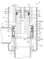
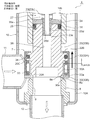
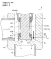
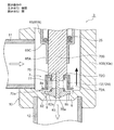
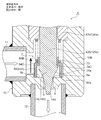
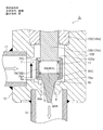
- FIG. 1 is an overall longitudinal sectional view showing a fully closed state of a first embodiment of a motor-operated valve according to the present invention
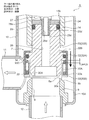
- FIG. 2 is an enlarged vertical sectional view of an essential part of the motor-operated valve shown in FIG.
- FIGS. 3 to 8 are enlarged vertical sectional views of the main part for explaining the configuration and operation of the motor-operated valve shown in FIGS.
- the gap formed between the members, the separation distance between the members, etc. are larger than the dimensions of each constituent member for easy understanding of the invention and for convenience of drawing. Or it may be drawn small.
- the motor-driven valve 1 of the illustrated embodiment is suitable for use as, for example, an expansion valve in a heat pump air conditioning system, and the fluid (refrigerant) is bidirectional (first flow direction from side to bottom and from bottom to side). In the second flow direction).
- the motor-operated valve 1 of the present embodiment includes a planetary gear speed reduction mechanism between the rotor and the screw feed mechanism so as to increase the axial force of the main valve body and improve the sealing performance. It has become.
- the motor-operated valve 1 includes a valve body 10 having a cylindrical base body 10A made of sheet metal, a main valve body 20 disposed in the valve body 10 so as to be movable up and down, and the main valve body 20 moved up and down.
- a stepping motor 50 attached to the upper side of the valve body 10 is provided.
- the tubular base body 10A of the valve body 10 is formed with a valve chamber 7, and a lateral first inlet / outlet (conduit joint) 11 that opens to the valve chamber 7 is attached to a side portion thereof, and at the bottom thereof, A vertical valve port 9 that opens from the lower side to the valve chamber 7, a main valve seat 8 a that consists of the inner peripheral corner of the upper end of the valve port 9, and a sub-valve seat 8 b that consists of the upper outer peripheral truncated cone surface of the valve port 9 are formed.
- the stepped valve seat member 8 is fixed, and a second inlet / outlet (conduit joint) 12 connected to the valve port 9 is attached to the valve seat member 8.
- a stepped cylindrical base 13 is attached to the upper surface opening of the cylindrical base body 10 ⁇ / b> A, and a cylindrical shape with a ceiling portion that constitutes a part of the stepping motor 50 is attached to the upper end of the cylindrical base 13.
- the lower end of the can 58 is hermetically joined by welding or the like.
- a cylindrical holding member 14 with a partition wall 14c is fixed to the inner peripheral side of the cylindrical base 13 by press-fitting or the like, and a bearing member provided with a female screw 15i on the lower inner periphery is provided above the cylindrical holding member 14. 15 is fixed by caulking.
- a spring chamber 14a Immediately above the partition wall 14c of the cylindrical holding member 14 is a spring chamber 14a in which a valve opening spring 25 made of a compression coil spring is accommodated.
- the main valve body 20 has a stepped cylindrical shape and is a poppet valve that opens and closes the valve port 9 by moving up and down in the vertical direction with respect to the main valve seat 8a.
- the main valve body 20 has a slightly large-diameter main valve body portion 20 ⁇ / b> A that opens and closes the valve port 9 in contact with and separates from the main valve seat 8 a of the valve seat member 8.
- the main body 20B has a body 20B above the main valve body 20A, and the upper portion of the body 20B is slidably inserted into the valve body guide hole 14b below the partition wall 14c in the cylindrical holding member 14.
- a reverse frustoconical seal surface 20a that is substantially in line contact with the main valve seat 8a is provided on the outer peripheral portion of the lower surface of the main valve body 20A so as to obtain a required sealing property.
- the subvalve body 30 for opening and closing the valve port 9 is arrange
- the sub-valve body 30 has a cylindrical portion 30A slidably fitted on the outer periphery of the lower portion of the main valve body 20, and the cylindrical portion 30A (the seal surface (lower end inner peripheral corner) 30a). Is vertically moved with respect to the auxiliary valve seat 8b to open and close the valve port 9.
- the upper flange-shaped portion 20C that serves as a retaining locking portion and a spring receiving portion (more specifically, the upper surface is a retaining locking portion and the lower surface is a spring receiving portion) is used as the main valve body portion 20A.
- a sub-valve body 30 having a cylindrical shape with a lower hook-shaped portion 30B (in other words, having a cylindrical portion 30A with a lower hook-shaped portion 30B) below the upper hook-shaped portion 20C. It is slidably extrapolated.
- an inner hook-like hook portion 32B that is locked to the upper hook-like portion 20C is provided at the upper end portion, and the lower end is provided on the outer peripheral portion of the upper face of the lower hook-like portion 30B.
- a cylindrical retaining member 32 having a portion fixed by welding or the like is disposed, and the auxiliary valve body 30 is disposed between the upper flange portion 20C (the lower surface thereof) and the lower flange portion 30B (the upper surface thereof).
- a compression coil spring 33 is deflated as a biasing member that always biases downward (in the valve closing direction).
- An O-ring 34 as a seal member is provided between the cylindrical portion 32A of the cylindrical retaining member 32 and the upper flange portion 20C (specifically, an annular groove formed on the outer periphery of the upper flange portion 20C). It is intervened.
- the sub-valve body 30 is sized and shaped so that the valve port 9 is closed before the main valve body 20 when the main valve body 20 is closed from the open state (rear). Details).
- the stepping motor 50 disposed on the upper side of the valve main body 10 has a two-phase coil portion including a yoke 51, a bobbin 52, a coil 53, a resin mold 54, etc. It has a stator 55 that is externally fitted and fixed, and a rotor 57 that is rotatably arranged in a can 58 and has a rotor support member 56 fixed to the inside of the upper portion thereof. Further, on the inner peripheral side of the rotor 57, a sun gear 41 provided integrally with the rotor support member 56 and a fixing ring fixed to the tip of the cylindrical body 14d fixed to the upper end of the cylindrical holding member 14 are provided.
- a mysterious planetary gear type reduction mechanism 40 comprising an output shaft 46 and the like fixed to the gear 45 is attached.
- the number of teeth of the fixed ring gear 47 is different from the number of teeth of the output gear 45.
- the lower portion of the support shaft 49 is inserted into a hole provided in the upper portion of the output shaft 46, and the carrier 44 and the sun gear 41 (rotor support member 56) are inserted into the support shaft 49.
- a support member 48 having substantially the same diameter as the inner diameter of the can 58 is disposed, and the upper portion of the support shaft 49 is a support member. It is inserted through a hole provided at the center of 48.
- the output shaft 46 of the mysterious planetary gear speed reduction mechanism 40 is rotatably inserted into the upper portion of the bearing member 15, and the rotation of the output shaft 46 is provided on the bearing member 15 and is screwed into the screw 15 i. It is transmitted to the rotary vertical movement shaft 17 provided with the screw 17e.
- a slit-like fitting portion 46a is provided at the lower portion of the output shaft 46, and a plate-like portion 17a that is slidably fitted to the slit-like fitting portion 46a is provided on the upper portion of the rotary vertical movement shaft 17 so as to project.
- a stepped cylindrical thrust transmission member 23 is disposed below the rotary vertical movement shaft 17 and the thrust downward of the rotary vertical movement shaft 17 is transmitted through the ball 18 and the ball seat 19. . Since the ball 18 is interposed, only the downward thrust is transmitted from the rotary vertical shaft 17 to the thrust transmission member 23 even if the rotary vertical shaft 17 is lowered while rotating, and the rotational force is Not transmitted.
- the thrust transmission member 23 includes, in order from the top, a large-diameter upper portion 23a in which the ball seat 19 is fitted on the inner periphery, an intermediate body portion 23b that is slidably inserted into the partition wall 14c of the cylindrical holding member 14, A small diameter lower portion 23c having a diameter smaller than that of the intermediate body portion 23b, and a through hole 26d constituting an upper portion of a pressure equalizing passage 26 described later and a plurality of horizontal holes 26e opened in a back pressure chamber 27 described later are formed therein. Is provided. The upper end opening of the through hole 26d is closed by the ball seat 19.
- the small diameter lower portion 23c of the thrust transmission member 23 is fitted and fixed to the upper fitting hole 20d of the stepped cylindrical main valve body 20 by press fitting or the like, and the main valve body 20 and the thrust transmission member 23 are moved up and down integrally. It is done.
- a pressing member 24 is sandwiched and fixed between the upper end surface of the main valve body 20 and the lower end step portion of the intermediate body portion 23b of the thrust transmission member 23 when the small diameter lower portion 23c is press-fitted.
- a seal member 29 made of an O-ring and a ring-shaped packing is mounted between an annular groove provided in the upper end portion of the main valve body 20 and the valve body guide hole 14b of the cylindrical holding member 14. .
- a valve opening spring 25 made of a compression coil spring is mounted with its lower end in contact with the partition wall 14c.
- the lifting spring receiver 28 having a hook-like hooking portion (upper hooking portion 28a, lower hooking portion 28b) on the upper and lower sides. Is distributed.
- the upper hooking portion 28 a of the pulling spring receiving body 28 is placed on the valve opening spring 25, and the lower hooking portion 28 b is configured to hook the lower end step portion of the large-diameter upper portion 23 a of the thrust transmission member 23.
- the screw feed mechanism is configured by the bearing member 15 provided with the female screw 15i and the rotary vertical movement shaft 17 provided with the male screw 17e, and the stepping motor 50 (rotor 57) rotates in one direction.
- the rotary vertical movement shaft 17 is rotated, for example, by rotating by the screw feed by the female screw 15i and the male screw 17e, and the thrust transmission member 23 and the main valve body 20 are opened by the thrust of the rotary vertical movement shaft 17.
- the valve spring 25 is pushed down against the urging force, and finally the seal surface 20a of the main valve body 20A is pressed against the main valve seat 8a, and the valve port 9 is closed.
- the stepping motor 50 (rotor 57) is rotated in the other direction, for example, the rotary vertical shaft 17 is rotated while being rotated by the screw feed by the female screw 15i and the external screw 17e, and accordingly, the thrust transmission member 23 and the main valve body 20 are pulled up by the urging force of the valve opening spring 25, and the seal surface 20a of the main valve body portion 20A is lifted (raised) from the main valve seat 8a to open the valve port 9.
- a back pressure chamber 27 is defined above the main valve body 20 and between the pressing member 24 and the partition wall 14c of the cylindrical holding member 14. Further, a stepped pressure equalizing passage 26 is provided in the main valve body 20 so as to communicate the front end portion (lower end portion) of the main valve body 20 with the back pressure chamber 27. The pressure equalizing passage 26 communicates with the back pressure chamber 27 together with the vertical hole 26d and the horizontal hole 26e of the thrust transmission member 23 described above.
- the balance between the push-down force (force acting in the valve closing direction) acting on the main valve body 20 and the push-up force (force acting in the valve opening direction) acting on the main valve body 20 in the valve closing state is canceled (the differential pressure is canceled).
- the diameter Da of the back pressure chamber 27 and the diameter Dc of the valve port 9 are set to be substantially the same.
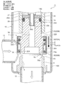
- the valve closing operation is completed and the main valve body 20 and the sub-valve body 30 are located at the lowest position, that is, the main valve body 20 is seated on the main valve seat 8a.
- the compression coil spring 33 is pushed down by the upper flange 20C.
- a gap La is formed between the lower surface of the upper hook-shaped portion 20C and the upper end of the cylindrical portion 30A of the subvalve body 30, and the upper surface of the upper hook-shaped portion 20C and the inner hook-shaped hook of the cylindrical retaining member 32 are provided.
- a gap Lb is formed between the lower surface of the portion 32B.
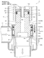
- the stepping motor 50 (rotor 57) is rotated in one direction, and the main valve body 20 is moved down with the sub-valve body 30.
- the sub valve body 30 is pushed down by the urging force of the compression coil spring 33, and the upper side
- the inner hook-shaped hook 32B (the lower surface) of the cylindrical retaining member 32 is abutted and locked to the hook-shaped portion 20C (the upper surface thereof), and the lower surface of the upper hook-shaped portion 20C and the cylindrical portion 30A of the subvalve body 30 are A gap La + Lb is left between the upper end.
- the lower end of the sub-valve body 30 is positioned below the lower end of the main valve body 20, and the refrigerant and foreign substances (metal powder, shaving residue) contained therein are included. , Abrasives, sludge, etc.) flow between the sub-valve body 30 and the sub-valve seat 8b and between the main valve body 20 and the main valve seat 8a.
- the main valve body 20 is further moved downward from the state where the main valve body 20 shown in FIG. 3 is slightly opened and the sub-valve body 30 is slightly opened.
- the valve closing operation until the sub valve body 30 is seated on the sub valve seat 8b and closes (2), that is, the gap formed between the sub valve body 30 and the sub valve seat 8b becomes gradually smaller.
- the foreign matter contained in the refrigerant is dammed up in a minute gap formed between the sub-valve element 30 and the sub-valve seat 8b, and the part indicated by the arrow E1 in FIG.
- the small gap formed between the sub-valve body 30 and the sub-valve seat 8b accumulates on the upstream side (outer peripheral side) and becomes clogged.
- the sub-valve element 30 is seated on the sub-valve seat 8b and closed, the foreign matter is blocked by the sub-valve element 30 and is downstream (here, the main valve body 20 and the main valve seat 8a on the inner peripheral side). Will not flow.
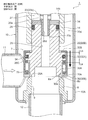
- the seal surface 20a of the main valve body 20 is seated on the main valve seat 8a and closed as shown in FIG. I speak.
- the main valve body 20 is strongly pressed against the main valve seat 8a by a high axial force by the mysterious planetary gear speed reduction mechanism 40.
- the compression coil spring 33 is pushed down by the gap Lb by the upper hook-shaped portion 20C, and between the lower surface of the upper hook-shaped portion 20C and the upper end of the cylindrical portion 30A of the subvalve body 30.
- the gap formed is only La to La + Lb, and a gap Lb is formed between the upper surface of the upper flange-shaped portion 20C and the lower surface of the inner hook-shaped hook portion 32B of the cylindrical retaining member 32, and the sub-valve element 30 is It is pressed against the auxiliary valve seat 8 b by the urging force of the compression coil spring 33.
- the stepping motor 50 (rotor 57) is rotated in the other direction, and thereby the main valve body 20 is pulled up as shown in FIG.
- the main valve body 20 is slightly opened from the closed state, and thereby, the cylindrical coil is retained on the upper surface of the upper flange-like portion 20C by the urging force of the compression coil spring 33.
- the lower surface of the inner hook-shaped hook portion 32B of the member 32 is abutted and locked, and the gap formed between the lower surface of the upper hook-shaped portion 20C and the upper end of the cylindrical portion 30A of the subvalve body 30 is from La.
- La + Lb and the sub-valve element 30 remains closed, but the pressing force by the compression coil spring 33 is reduced.
- FIGS. 7 and 8 states corresponding to FIGS. 3 and 4 at the time of the second flow from the bottom to the side.
- the main valve body 20 is moved downward from the state where the main valve body 20 is slightly opened and the sub-valve body 30 is slightly opened, and is formed between the sub-valve body 30 and the sub-valve seat 8b.
- the gap becomes gradually smaller and finally becomes 0, the foreign matter contained in the refrigerant is blocked by a minute gap formed between the sub-valve body 30 and the sub-valve seat 8b.
- the gap formed is only La to La + Lb, and a gap Lb is formed between the upper surface of the upper flange-shaped portion 20C and the lower surface of the inner hook-shaped hook portion 32B of the cylindrical retaining member 32, and the sub-valve element 30 is It is pressed against the auxiliary valve seat 8 b by the urging force of the compression coil spring 33.
- the auxiliary valve body 30 that closes the valve port 9 before the main valve body 20 is provided on the outer periphery of the main valve body 20.
- the fluid refrigerant
- the auxiliary valve body 30 that closes the valve port 9 before the main valve body 20 is provided on the outer periphery of the main valve body 20.
- the rotor 57 and the screw feed mechanism (the bearing member 15 provided with the female screw 15i, A strange planetary gear speed reduction mechanism 40 is interposed between the rotary vertical movement shaft 17) provided with the male screw 17e, and the axial force of the main valve body 20, that is, the main valve body 20 is applied to the main valve seat 8a.
- the pressing force is increased, it is difficult to cause a situation in which foreign matter contained in the fluid (refrigerant) is caught between the main valve body 20 and the main valve seat 8a and strongly pressed against them.
- the main valve seat 8a, the sub-valve seat 8b, the main valve body 20, and the sub-valve body 30 can be prevented from being scratched or dented. As a result, valve leakage can be effectively prevented and the reliability of valve closing can be improved.
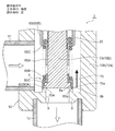
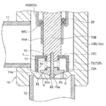
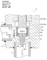
- FIG. 9 is an overall longitudinal sectional view showing the fully closed state of the second embodiment of the electric valve according to the present invention.
- FIGS. 10 to 13 are enlarged vertical sectional views of the main part for explaining the configuration and operation of the motor-operated valve shown in FIG.
- the motor-operated valve 2 of the illustrated second embodiment has substantially the same configuration as the motor-operated valve 1 of the first embodiment shown in FIGS. 1 to 8 except for the main valve body and the sub-valve body. For this reason, portions corresponding to the respective portions of the motor-operated valve 1 of the first embodiment and portions having similar functions are denoted by common reference numerals, and redundant description is omitted. The explanation will be focused on.
- a cylindrical base body 10 ⁇ / b> B constituting the valve body 10 includes a large-diameter lower cylindrical portion 10 a with a bottom, an intermediate thick portion 10 b, and an upper cylindrical portion 10 c inserted into a can 58.
- a valve chamber 7 is formed in the lower cylindrical portion 10a of the tubular base body 10B, and a lateral first inlet / outlet (conduit joint) 11 that opens to the valve chamber 7 is attached to a side portion of the valve chamber 7 and the bottom portion thereof.
- a vertical valve port 9 that opens from the lower side to the valve chamber 7, a main valve seat 8 a that consists of the inner peripheral corner of the upper end of the valve port 9, and a sub-valve seat 8 b that consists of the upper outer peripheral truncated cone surface of the valve port 9
- a valve seat portion 8 is formed integrally (see FIGS. 10 to 13), and a second inlet / outlet (conduit joint) 12 connected to the valve port 9 is attached to the valve seat portion 8.
- a ring-shaped base 13 is attached to an outer peripheral step portion of the intermediate thick portion 10b of the cylindrical base body 10B, and a lower end of a cylindrical can 58 with a ceiling portion is attached to an upper end outer peripheral portion of the ring-shaped base 13.
- the parts are hermetically joined by welding or the like.
- a base portion of the upper cylindrical portion 10c of the cylindrical base body 10B is fixed to the inner peripheral side of the ring-shaped base 13 by press-fitting or the like, and a female screw 15i is provided on the lower inner periphery of the upper cylindrical portion 10c of the cylindrical base body 10B.
- the bearing member 15 is fixed by caulking.
- a sheet metal stepped cylindrical body 65 serving as both a spring receiving portion and a main valve body guide portion.
- a bowl-shaped portion 65D is sandwiched.
- the stepped cylindrical body 65 includes a lower small-diameter guide portion 65A in which a main valve body 70 (body portion 70B) is slidably inserted via an annular step (step) portion 65C between the upper end and the upper end.
- the valve-opening spring 25 comprising a compression coil spring is mounted between the stepped portion 65C and the large-diameter upper portion 23a of the thrust transmission member 23. ing.
- the main valve body 70 is a poppet valve that moves up and down in the vertical direction with respect to the main valve seat 8a to open and close the valve port 9.
- the main valve body 70 has a large-diameter main valve body portion 70A that opens and closes the valve port 9 by contacting and separating from the main valve seat 8a of the valve seat portion 8, and a small-diameter body portion above the main valve body portion 70A.
- a reverse frustoconical seal surface 70a that is substantially in line contact with the main valve seat 8a is provided on the outer periphery of the lower surface of the main valve body 70A so as to obtain a required sealing property ( (See FIGS. 10 to 13).
- the subvalve body 80 for opening and closing the valve port 9 is arrange
- the auxiliary valve body 80 is slidably extrapolated to a large-diameter outer insertion portion 80A that is slidably inserted on the outer periphery of the main valve body portion 70A of the main valve body 70, and a body portion 70B of the main valve body 70.
- the small-diameter extrapolation portion 80B, and the large-diameter extrapolation portion 80A and the small-diameter extrapolation portion 80B also serve as a retaining engagement portion and a spring receiving portion (specifically, the lower surface is a retaining engagement portion, and the upper surface is A stepped cylindrical shape including an annular step (terrace) portion 80 ⁇ / b> C (used as a spring receiving portion).
- the sub-valve body 80 is always urged downward (in the valve closing direction) between the stepped portion 80C and the stepped portion 65C of the stepped cylindrical body 65 that is a fixed portion above the stepped portion 80C provided in the valve body 10.
- a compression coil spring 73 serving as an urging member is mounted.
- the large-diameter extrapolation portion 80A (the sealing surface (the lower end inner peripheral corner portion) 80a) moves up and down in the vertical direction with respect to the auxiliary valve seat 8b to open and close the valve port 9. .
- a sealing member such as an O-ring may be interposed between the sliding surfaces of the small-diameter outer insertion portion 80B of the sub valve body 84 and the body portion 70B of the main valve body 70.
- the valve closing operation is completed, that is, the main valve body 70 is seated and pressed against the main valve seat 8a, and the sub-valve body 80 is seated and pressed against the sub-valve seat 8b.
- a gap Lc is provided between the upper surface of the main valve body portion 70A and the lower surface of the stepped portion 80C of the sub valve body 80.
- the stepping motor 50 (rotor 57) is rotated in one direction, and the main valve body 70 is moved down along with the sub valve body 80.
- the sub-valve body 80 is pushed down by the urging force of the compression coil spring 73, and the stepped portion 80C of the sub-valve body 80 comes into contact with the upper surface of the main valve body portion 70A.
- the lower end of the sub-valve element 80 is located lower than the lower end of the main valve element 70, and the refrigerant and foreign substances (metal powder, shavings, abrasive, sludge, etc. contained therein) ) Flows between the auxiliary valve body 80 and the auxiliary valve seat 8b and between the main valve body 70 and the main valve seat 8a.
- the main valve body 70 is further moved downward from the state in which the main valve body 70 is slightly opened and the sub-valve body 80 is slightly opened as shown in FIG.
- the valve closing operation until the sub valve body 80 is seated on the sub valve seat 8b and closes (2), that is, the gap formed between the sub valve body 80 and the sub valve seat 8b becomes gradually smaller.
- the foreign matter contained in the refrigerant is dammed up in a minute gap formed between the sub-valve element 80 and the sub-valve seat 8b, and the part indicated by the arrow E1 in FIG.
- the small gap formed between the sub-valve body 80 and the sub-valve seat 8b accumulates on the upstream side (outer peripheral side) and becomes clogged.
- the sub-valve element 80 is seated on the sub-valve seat 8b and closed, the foreign matter is blocked by the sub-valve element 80 and downstream (here, the main valve element 70 on the inner peripheral side and the main valve seat 8a side). Will not flow.
- the sub-valve body 80 is applied to the sub-valve seat 8 b by the urging force of the compression coil spring 73 as shown in FIG. 12.
- the main valve body 70 is seated on the main valve seat 8a and is strongly pressed against the main valve seat 8a with a high axial force by the mysterious planetary gear type speed reduction mechanism 40, and is in a fully closed state.
- the gap Lc is provided between the upper surface of the main valve body portion 70A and the lower surface of the stepped portion 80C of the sub valve body 80 as described above.
- the stepping motor 50 (rotor 57) is rotated in the other direction, whereby the main valve body 70 is pulled up and opened as shown in FIG. I speak.
- the upper surface of the main valve body portion 70A comes into contact with the lower surface of the stepped portion 80C of the sub-valve body 80.
- the auxiliary valve body 80 is pulled up, the sealing surface 80a of the auxiliary valve body 80 is separated from the auxiliary valve seat 8b, and the auxiliary valve body 80 is also opened.
- the auxiliary valve body 80 that closes the valve port 9 before the main valve body 70 is provided on the outer periphery of the main valve body 70.
- the valve body 80 When the valve body 80 is in the slightly opened state, foreign matter contained in the fluid (refrigerant) is blocked by the sub-valve element 80, and when the sub-valve element 80 is closed from there, the fluid (refrigerant) does not substantially flow. Therefore, no foreign matter is caught between the main valve body 70 and the main valve seat 8a. Therefore, even if the main valve body 70 is closed and strongly pressed against the main valve seat 8a, the main valve body 70 The main valve seat 8a is not scratched or dented.
- the foreign matter contained in the fluid is caught between the main valve body 70 and the main valve seat 8a and strongly resists them. Therefore, the main valve seat 8a, the sub-valve seat 8b, the main valve body 70, and the sub-valve body 80 can be prevented from being scratched or dented. As a result, valve leakage can be effectively prevented and the reliability of valve closing can be improved.
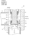
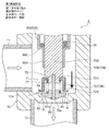
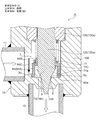
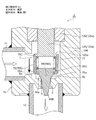
- FIG. 14 to FIG. 17 are enlarged vertical sectional views of the main part for explaining the configuration and operation of the third embodiment of the motor-operated valve according to the present invention.
- the motor-operated valve 3 of the third embodiment shown in the figure has substantially the same configuration except for the main valve body and the sub-valve body of the motor-operated valve 2 of the second embodiment shown in FIGS. For this reason, portions corresponding to the respective portions of the motor-operated valve 2 of the second embodiment and portions having similar functions are denoted by common reference numerals, and redundant description is omitted. The explanation will be focused on.
- a main valve seat 8 a is provided on the outer peripheral side (corner portion) of the valve seat portion 8, contrary to the motor-operated valve 2 of the second embodiment.
- a secondary valve seat 8b is provided on the circumferential side (corner portion).
- the main valve body 72 is cylindrical
- the sub-valve element 82 is an inverted frustoconical shape
- the main valve element 72 (the reverse frustoconical seal surface 72a of the main valve element portion 72A) is the sub-valve element 82.
- An inverted frustoconical sealing surface 82a) is located on the outer peripheral side (in other words, the sub-valve element 82 is inside the main valve element 72).
- the main valve body 72 projects outward from the lower end of the cylindrical body 72B and the cylindrical body 72B, and has a bowl-shaped main valve body 72A having an inverted frustoconical seal surface 72a. And an upper inner flange portion 72C that protrudes inward from the upper end of the cylindrical barrel portion 72B and is fixed to the lower end portion of the barrel portion 70B in the second embodiment by press-fitting or the like.
- the upper end portion of the sub-valve support rod 75, into which the sub-valve element 82 is slidably inserted, is fixed to the lower center of the body portion 70B by press-fitting or the like.
- a large-diameter retaining member that fits into a lower-end recess 83 provided on the distal end surface (lower-end surface) of the sub-valve element 82 and retains the sub-valve element 82 at the lower end of the sub-valve support rod 75.
- a stop 75a is provided.
- the front end surface (lower end surface) of the sub-valve element 82 moves up and down in the vertical direction with respect to the sub-valve seat 8b inside the main valve seat 8a, and opens and closes the valve port 9. 82a.
- the valve closing operation is completed, that is, the main valve body 72 is seated and pressed against the main valve seat 8a, and the sub-valve body 82 is seated and pressed against the sub-valve seat 8b.
- a gap Ld is formed between the upper surface of the lower end recess 83 of the sub-valve element 82 and the upper surface of the retaining engagement part 75a of the sub-valve support rod 75. It is vacated.
- the stepping motor 50 (rotor 57) is rotated in one direction, and the main valve body 72 is moved downward along with the sub valve body 82.
- the sub-valve element 82 is pushed down by the urging force of the compression coil spring 77 so that the sub-valve element 82 contacts the retaining engagement portion 75a of the sub-valve element support rod 75.
- the lower end of the sub-valve element 82 is positioned on the lower side of the lower end of the main valve element 72, and the refrigerant and foreign substances (metal powder, shavings, abrasive, sludge) contained therein. Etc.) is passed between the sub-valve element 82 and the sub-valve seat 8b and between the main valve element 72 and the main valve seat 8a.
- the main valve body 72 is further moved downward from the state where the main valve body 72 shown in FIG. 14 is slightly opened and the sub-valve element 82 is slightly opened.
- the valve closing operation until the sub-valve element 82 is seated on the sub-valve seat 8b and closes (2), that is, the gap formed between the sub-valve element 82 and the sub-valve seat 8b becomes gradually smaller.
- the foreign matter contained in the refrigerant is blocked by a minute gap formed between the sub-valve element 82 and the sub-valve seat 8b, and between the sub-valve element 82 and the sub-valve seat 8b.
- the sub-valve element 82 is applied to the sub-valve seat 8 b by the urging force of the compression coil spring 77 as shown in FIG. 16.
- the main valve body 72 is seated on the main valve seat 8a and pressed strongly against the main valve seat 8a with a high axial force by the mysterious planetary gear speed reduction mechanism 40, so that the valve is fully closed.
- the gap Ld is provided between the upper surface of the lower end recess 83 of the sub-valve element 82 and the upper surface of the retaining engagement portion 75a of the sub-valve support rod 75 as described above.
- the stepping motor 50 (rotor 57) is rotated in the other direction, whereby the main valve body 72 is pulled up and opened as shown in FIG. I speak.
- the upper surface of the retaining engagement part 75a of the sub-valve element support rod 75 comes into contact with the upper surface of the lower end recess 83 of the sub-valve element 82, and the main valve element 72 is further exceeded.
- the sub-valve element 82 is pulled up, the seal surface 82a of the sub-valve element 82 is separated from the sub-valve seat 8b, and the sub-valve element 82 is also opened.
- the main valve seat 8a is provided at the outer peripheral corner of the valve seat 8, and the sub valve seat 8b is provided at the inner peripheral corner of the valve seat 8.
- the upper surface of the valve seat portion 8 is an inclined surface
- the main valve seat 8a is provided on the inclined surface
- the auxiliary valve seat is provided at the inner end (corner portion) of the inclined surface. 8b may be provided.
- the lower end portion of the cylindrical body portion 72B of the main valve body 72 may be the main valve body portion 72A having the seal surface 72a.
- the valve port 9 is provided on the inner periphery of the main valve body 72 as in the motor operated valves 1 and 2 of the first embodiment and the second embodiment. Since the sub-valve element 82 that is closed before the body 72 is provided, when the sub-valve element 82 is in the slightly open state, foreign matter contained in the fluid (refrigerant) is blocked by the sub-valve element 82, Since the fluid (refrigerant) does not substantially flow when the sub-valve element 82 is closed from there, foreign matter is not caught between the main valve element 72 and the main valve seat 8a. Even when the valve is closed and strongly pressed against the main valve seat 8a, the main valve body 72 and the main valve seat 8a are not damaged or dented.
- the foreign matter contained in the fluid is caught between the main valve body 72 and the main valve seat 8a and strongly resists them.
- the main valve seat 8a, the sub-valve seat 8b, the main valve body 72, and the sub-valve body 82 can be prevented from being scratched or dented.
- valve leakage can be effectively prevented and the reliability of valve closing can be improved.
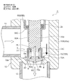
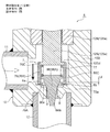
- FIG. 19 is an overall longitudinal sectional view showing a fully closed state of the fourth embodiment of the electric valve according to the present invention.
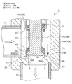
- 20 to 23 are enlarged vertical cross-sectional views of a main part for explaining the configuration and operation of the motor-operated valve shown in FIG.
- the motor-operated valve 4 of the illustrated fourth embodiment is a direct-acting type, and is mainly related to the mysterious planetary gear speed reduction mechanism 40 and the motor-driven valve 2 of the second embodiment shown in FIGS. 9 to 13 and related thereto. It is set as the structure which removed the part, and the main valve body, the subvalve body, etc. are made into the shape similar to the thing of 2nd Embodiment. For this reason, portions corresponding to the respective portions of the motor-operated valve 2 of the second embodiment and portions having similar functions are denoted by common reference numerals and redundant description is omitted, and the following description will focus on differences.
- the motor-operated valve 4 of the illustrated embodiment basically has a bottomed tube provided with a valve shaft 125 integrally provided with a main valve element 74, a valve chamber 7, a valve port 9, a valve seat 8 and the like.
- a valve body 10 having a cylindrical base 10B, a cylindrical can 58 with a ceiling portion whose lower end portion is sealed and joined to the valve body 10 by welding or the like, and a predetermined gap on the inner periphery of the can 58.
- a stepping motor 50 comprising a rotor 57 and a stator 55 externally fitted to the can 58 to rotationally drive the rotor 57; and the rotor 57 and the main valve body 74, A screw feed mechanism for making the main valve body 74 contact and separate from the main valve seat 8a formed in the valve seat portion 8 by utilizing the rotation of the rotor 57;
- a support ring 136 is integrally coupled to the rotor 57, and a cylindrical valve shaft holder 132 is formed on the support ring 136 at a lower opening disposed on the outer periphery of the valve shaft 125 and the guide bush 126.
- the upper protrusion is caulked and fixed, whereby the rotor 57, the support ring 136, and the valve shaft holder 132 are integrally connected.
- the screw feed mechanism has a lower end portion 126a press-fitted and fixed to a fitting hole 142 provided in the tubular base body 10B of the valve body 10, and a valve shaft 125 (a lower large diameter portion 125a) is slidable.
- a fixed screw portion (male screw portion) 128 formed on the outer periphery of the cylindrical guide bush 126 inserted therein and an inner periphery of the valve shaft holder 132 and screwed to the fixed screw portion 128.
- the moving screw part (female screw part) 138 is comprised.
- the upper small diameter portion 126b of the guide bush 126 is inserted into the upper portion of the valve shaft holder 132, and the upper small diameter portion 125b of the valve shaft 125 is formed at the center of the ceiling portion of the valve shaft holder 132 (through hole formed therein). It is inserted.
- a push nut 133 is press-fitted and fixed to the upper end portion of the upper small diameter portion 125b of the valve shaft 125 (the portion protruding upward from the through hole of the valve shaft holder 132).
- the valve shaft 125 is extrapolated to the upper small diameter portion 125b of the valve shaft 125, and is contracted between the ceiling portion of the valve shaft holder 132 and the upper terrace surface of the lower large diameter portion 125a of the valve shaft 125.
- the valve closing spring 134 composed of a mounted compression coil spring is always urged downward (in the valve closing direction).
- a return spring 135 made of a coil spring is provided on the outer periphery of the push nut 133 on the ceiling of the valve shaft holder 132.
- the guide bush 126 has a lower stopper body (fixed stopper) that constitutes one of rotation lowering stopper mechanisms for preventing further rotation lowering when the rotor 57 is rotated downward to a predetermined valve closing position. 127 is fixed, and an upper stopper body (moving stopper) 137 constituting the other of the rotation lowering stopper mechanism is externally fixed to the valve shaft holder 132.
- a screw feed comprising a fixed screw portion (male screw portion) 128 and a moving screw portion (female screw portion) 138 screwed to the fixing screw portion (male screw portion) 138.
- the valve shaft 125 is rotated upward, for example, and the seal surface 74a of the main valve body 74 is moved away from the main valve seat 8a (see FIGS. 20 to 23), thereby opening the valve port 9. .
- the main valve body 74 is a seal formed by a locking large-diameter portion 74C that is connected to the lower portion of the valve shaft 125 and has a slightly larger diameter than the valve shaft 125, and an inverted truncated cone surface. It has a main valve body portion 74A having a surface 74a and an inverted truncated cone-shaped tapered lower portion 74B that is connected to the lower side of the main valve body portion 74A and is inserted into the valve port 9.
- a sub-valve element 84 for opening and closing the valve port 9 is slidably disposed in the vertical direction below the valve shaft 125 and on the outer peripheral side of the main valve element 74.
- the sub-valve element 84 is slidable to a lower part of the valve shaft 125 and a large-diameter valve element part (large-diameter extrapolation part) 84A arranged on the outer peripheral side of the main valve element part 74A (with a gap).
- the stepped portion 84 ⁇ / b> C is latched and locked to the locking large diameter portion 74 ⁇ / b> C of the main valve body 74.
- the large-diameter valve body portion 84A (the seal surface (lower flat surface) 84a thereof) moves up and down in the vertical direction with respect to the sub-valve seat 8b formed of a flat surface formed on the upper surface of the valve seat portion 8.
- the valve port 9 is opened and closed.
- the sub-valve body 84 is always positioned downward (between the stepped portion 84C of the sub-valve body 84 and the lower end portion 126a of the guide bush 126, which is a stationary portion above the stepped portion 80C provided in the valve body 10 ( A compression coil spring 73 as a biasing member biasing in the valve closing direction) is mounted.
- a seal member such as an O-ring may be interposed between the sliding surfaces of the small diameter extrapolation portion 84B of the sub-valve element 84 and the lower portion of the valve shaft 125.
- the valve closing operation is completed, that is, the main valve element 74 is seated and pressed against the main valve seat 8a, and the sub valve element 84 is When seated and pressed against the valve seat 8b and closed together (when fully closed), a gap Le is made between the upper surface of the large-diameter portion for locking 74C and the lower surface of the stepped portion 84C. .
- the outer periphery of the main valve body 74 is the same as the motor-operated valve 2 of the second embodiment.
- the auxiliary valve body 84 that closes the valve port 9 before the main valve body 74 is provided, when the auxiliary valve body 84 is in a slightly opened state, foreign substances contained in the fluid (refrigerant) Since the fluid (refrigerant) does not substantially flow when the valve body 84 is blocked by the valve body 84 and the sub-valve body 84 is closed therefrom, foreign matter is not caught between the main valve body 74 and the main valve seat 8a. Therefore, even if the main valve body 74 is closed and strongly pressed against the main valve seat 8a, the main valve body 74 and the main valve seat 8a are not damaged or dented.
- the foreign matter contained in the fluid is caught between the main valve body 74 and the main valve seat 8a and strongly resists them.
- the main valve seat 8a, the sub-valve seat 8b, the valve disc 74, and the sub-valve 84 can be prevented from being scratched or dented.
- valve leakage can be effectively prevented and the reliability of valve closing can be improved.
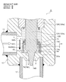
- FIGS. 24 to 27 are enlarged vertical sectional views of main parts for explaining the configuration and operation of the fifth embodiment of the motor-operated valve according to the present invention.
- the motor-driven valve 5 of the illustrated fifth embodiment is the same as the motor-operated valve 4 of the fourth embodiment (see FIG. 19) except for the main valve body and the sub-valve body.
- the structure around the valve body is similar to the motor-operated valve 3 of the third embodiment shown in FIGS. Therefore, portions corresponding to the respective portions of the motor-operated valves 3 and 4 of the third and fourth embodiments and portions having similar functions are denoted by common reference numerals, and redundant description is omitted, and in the following, the main valve body is omitted. And the surroundings of the subvalve will be briefly described.
- the motor-operated valve 5 of the illustrated embodiment is opposite to the motor-operated valve 4 of the fourth embodiment and has the same configuration as that of the motor-operated valve 3 of the third embodiment.
- the main valve seat 8a is provided in the part), and the sub-valve seat 8b is provided on the inner peripheral side (corner part) of the valve seat part 8.
- the main valve body 76 has a cylindrical shape
- the sub-valve element 86 has a stepped inverted truncated cone shape
- the main valve element 76 (the reverse truncated cone-shaped sealing surface 76a of the main valve element portion 76A) is the auxiliary valve.
- the body 86 (the reverse frustoconical sealing surface 86a of the sub-valve body portion 86A) is located on the outer peripheral side (in other words, the sub-valve body 86 is inside the main valve body 76).
- the main valve body 76 includes a cylindrical body portion 76B, and a main valve body portion 76A having an inverted frustoconical seal surface 76a composed of a lower end portion of the cylindrical body portion 76B and an inner peripheral protruding portion. And an upper end fixing portion 76C fixed to the lower end flange portion 125d formed on the valve shaft 125 by press-fitting or the like.
- the inner peripheral protrusion that constitutes the main valve body portion 76A retains the sub-valve body 86 (the upper flange portion 86C) that is slidably inserted into the cylindrical body portion 76B. It is a stop.
- the upper part of the sub-valve element 86 is slidably inserted on the inner peripheral side of the main valve element 76. That is, the sub-valve body 86 serves as a retaining engagement portion and a spring receiving portion that are slidably inserted into the cylindrical body portion 76B of the main valve body 70 in order from the top (specifically, the bottom surface is An upper flange-like portion 86C (which is a retaining latch portion, the upper surface is a spring receiving portion), and an inverted frustoconical seal surface 86a disposed inside the main valve body portion 76A (with a gap) are provided.
- the sub-valve body portion 86A is formed, and an inverted frustoconical tapered lower portion 86B that is connected to the lower side of the sub-valve body portion 86A and is inserted into the valve port 9.
- the auxiliary valve body 86 is always placed between the lower flange portion 125d of the valve shaft 125 (the portion connected to the upper end fixing portion 76C of the main valve body 76) and the upper flange portion 86C of the auxiliary valve body 86.
- a compression coil spring 77 as a biasing member that biases downward (in the valve closing direction) is mounted.
- the valve closing operation is completed, that is, the main valve body 76 is seated and pressed against the main valve seat 8a, and the sub valve body 86 is When seated on and pressed against the valve seat 8b and closed together (when fully closed), the upper surface of the inner circumferential protrusion (prevention locking portion) of the main valve body 76A and the upper hook-like portion 86C A gap Lf is formed between the lower surface.
- motor-operated valve is not limited to the configuration of each embodiment described above, and for example, the configuration around the main valve body and the sub-valve body can be variously changed.
Landscapes
- Engineering & Computer Science (AREA)
- General Engineering & Computer Science (AREA)
- Mechanical Engineering (AREA)
- Electrically Driven Valve-Operating Means (AREA)
- Lift Valve (AREA)
Priority Applications (1)
| Application Number | Priority Date | Filing Date | Title |
|---|---|---|---|
| CN201980014366.5A CN111742169B (zh) | 2018-02-20 | 2019-01-11 | 电动阀 |
Applications Claiming Priority (2)
| Application Number | Priority Date | Filing Date | Title |
|---|---|---|---|
| JP2018-028011 | 2018-02-20 | ||
| JP2018028011A JP6902789B2 (ja) | 2018-02-20 | 2018-02-20 | 電動弁 |
Publications (1)
| Publication Number | Publication Date |
|---|---|
| WO2019163319A1 true WO2019163319A1 (ja) | 2019-08-29 |
Family
ID=67687607
Family Applications (1)
| Application Number | Title | Priority Date | Filing Date |
|---|---|---|---|
| PCT/JP2019/000714 Ceased WO2019163319A1 (ja) | 2018-02-20 | 2019-01-11 | 電動弁 |
Country Status (3)
| Country | Link |
|---|---|
| JP (1) | JP6902789B2 (enExample) |
| CN (1) | CN111742169B (enExample) |
| WO (1) | WO2019163319A1 (enExample) |
Cited By (1)
| Publication number | Priority date | Publication date | Assignee | Title |
|---|---|---|---|---|
| CN113775767A (zh) * | 2020-06-10 | 2021-12-10 | 浙江三花制冷集团有限公司 | 一种电动阀及电动阀的装配方法 |
Families Citing this family (8)
| Publication number | Priority date | Publication date | Assignee | Title |
|---|---|---|---|---|
| CN114173952B (zh) | 2019-08-05 | 2024-08-13 | 日本制铁株式会社 | 冲压成型品的制造方法、冲压成型品以及冲压成型装置 |
| CN112413136B (zh) * | 2020-10-15 | 2021-06-25 | 深圳市安保科技有限公司 | 一种比例流量阀 |
| JP7519265B2 (ja) * | 2020-10-26 | 2024-07-19 | 株式会社鷺宮製作所 | 電動弁および冷凍サイクルシステム |
| JP7550465B2 (ja) * | 2022-04-11 | 2024-09-13 | 株式会社不二工機 | 電動弁 |
| JP7550466B2 (ja) * | 2022-04-11 | 2024-09-13 | 株式会社不二工機 | 電動弁 |
| DE102024124256A1 (de) * | 2023-09-22 | 2025-03-27 | Hanon Systems | Vorrichtung zum Regeln eines Durchflusses und Verteilen eines Fluids in einem Fluidkreislauf |
| JP2025101953A (ja) * | 2023-12-26 | 2025-07-08 | 株式会社不二工機 | 電動弁 |
| JP2025101948A (ja) * | 2023-12-26 | 2025-07-08 | 株式会社不二工機 | 電動弁 |
Citations (7)
| Publication number | Priority date | Publication date | Assignee | Title |
|---|---|---|---|---|
| JPS58101057U (ja) * | 1981-12-29 | 1983-07-09 | 株式会社ノーリツ | 電磁弁 |
| US4529168A (en) * | 1982-02-01 | 1985-07-16 | Jeumont-Schneider Corporation | Double shut-off valve which provides perfectly tight sealing |
| US20030098074A1 (en) * | 2001-11-27 | 2003-05-29 | Toshihiro Kayahara | Valve |
| US20050166979A1 (en) * | 2004-01-30 | 2005-08-04 | Karl Dungs Gmbh & Co. | Solenoid valve |
| US20120211683A1 (en) * | 2011-02-21 | 2012-08-23 | Fujikoki Corporation | Valve apparatus |
| US20140225017A1 (en) * | 2013-02-13 | 2014-08-14 | Buerkert Werke Gmbh | Solenoid valve |
| JP2017211032A (ja) * | 2016-05-26 | 2017-11-30 | 株式会社不二工機 | 流量調整弁 |
Family Cites Families (9)
| Publication number | Priority date | Publication date | Assignee | Title |
|---|---|---|---|---|
| DE10114175C1 (de) * | 2001-03-23 | 2002-08-29 | Dungs Karl Gmbh & Co | Koaxialmagnetventil |
| CA2459088C (en) * | 2004-02-27 | 2012-08-21 | Dana Canada Corporation | Leak-resistant solenoid valve |
| CN2906226Y (zh) * | 2006-04-19 | 2007-05-30 | 黄依华 | 防漏阀结构 |
| JP4881137B2 (ja) * | 2006-11-24 | 2012-02-22 | 株式会社不二工機 | 流量制御弁及び冷凍サイクル |
| CN102345743B (zh) * | 2010-07-28 | 2015-06-17 | 赵诗华 | 自锁式双截止阀 |
| DE102011120287B3 (de) * | 2011-12-03 | 2012-11-15 | Gea Tuchenhagen Gmbh | Antrieb zum Schalten eines Doppelsitzventils |
| JP5926552B2 (ja) * | 2011-12-12 | 2016-05-25 | 株式会社不二工機 | 電動弁 |
| JP5901960B2 (ja) * | 2011-12-22 | 2016-04-13 | 株式会社不二工機 | 電動弁 |
| WO2014098073A1 (ja) * | 2012-12-21 | 2014-06-26 | 三菱重工業株式会社 | 蒸気弁及び蒸気タービン |
-
2018
- 2018-02-20 JP JP2018028011A patent/JP6902789B2/ja active Active
-
2019
- 2019-01-11 WO PCT/JP2019/000714 patent/WO2019163319A1/ja not_active Ceased
- 2019-01-11 CN CN201980014366.5A patent/CN111742169B/zh active Active
Patent Citations (7)
| Publication number | Priority date | Publication date | Assignee | Title |
|---|---|---|---|---|
| JPS58101057U (ja) * | 1981-12-29 | 1983-07-09 | 株式会社ノーリツ | 電磁弁 |
| US4529168A (en) * | 1982-02-01 | 1985-07-16 | Jeumont-Schneider Corporation | Double shut-off valve which provides perfectly tight sealing |
| US20030098074A1 (en) * | 2001-11-27 | 2003-05-29 | Toshihiro Kayahara | Valve |
| US20050166979A1 (en) * | 2004-01-30 | 2005-08-04 | Karl Dungs Gmbh & Co. | Solenoid valve |
| US20120211683A1 (en) * | 2011-02-21 | 2012-08-23 | Fujikoki Corporation | Valve apparatus |
| US20140225017A1 (en) * | 2013-02-13 | 2014-08-14 | Buerkert Werke Gmbh | Solenoid valve |
| JP2017211032A (ja) * | 2016-05-26 | 2017-11-30 | 株式会社不二工機 | 流量調整弁 |
Cited By (1)
| Publication number | Priority date | Publication date | Assignee | Title |
|---|---|---|---|---|
| CN113775767A (zh) * | 2020-06-10 | 2021-12-10 | 浙江三花制冷集团有限公司 | 一种电动阀及电动阀的装配方法 |
Also Published As
| Publication number | Publication date |
|---|---|
| CN111742169B (zh) | 2023-06-23 |
| JP2019143704A (ja) | 2019-08-29 |
| CN111742169A (zh) | 2020-10-02 |
| JP6902789B2 (ja) | 2021-07-14 |
Similar Documents
| Publication | Publication Date | Title |
|---|---|---|
| WO2019163319A1 (ja) | 電動弁 | |
| JP7333976B2 (ja) | 電動弁 | |
| JP5597468B2 (ja) | エアオペレートバルブ | |
| EP3336396B1 (en) | Electronic expansion valve | |
| JP5055013B2 (ja) | 電動弁 | |
| JP7058744B2 (ja) | 電子膨張弁 | |
| CN216009572U (zh) | 电动阀以及冷冻循环系统 | |
| JP2000227165A (ja) | 電動式コントロールバルブ | |
| CN110500424B (zh) | 三通切换阀 | |
| EP1724402A1 (en) | Self-sealing floor drainage | |
| US3955794A (en) | Hermetically sealed valve with fixed diffuser | |
| CN214743672U (zh) | 电动阀以及冷冻循环系统 | |
| US11578807B2 (en) | Outlet valve | |
| JP6945504B2 (ja) | 電動弁および冷凍サイクルシステム | |
| US20080072967A1 (en) | Self-sealing floor drain | |
| JP7550466B2 (ja) | 電動弁 | |
| JP4065648B2 (ja) | 電動弁 | |
| JP5911706B2 (ja) | 電動弁 | |
| CN112360991A (zh) | 一种双座调节阀 | |
| JP7550465B2 (ja) | 電動弁 | |
| CN223563494U (zh) | 一种带锁紧机构的全金属密封手动波纹管调节阀 | |
| CN108916400A (zh) | 一种适用于特大流量控制的水液压液控开关阀 | |
| CN120720465A (zh) | 一种先导式双隔磁管电磁阀 | |
| CN119712858A (zh) | 一种带截止功能的节流阀 | |
| CN113738897A (zh) | 一种防锁死截止阀 |
Legal Events
| Date | Code | Title | Description |
|---|---|---|---|
| 121 | Ep: the epo has been informed by wipo that ep was designated in this application |
Ref document number: 19756651 Country of ref document: EP Kind code of ref document: A1 |
|
| NENP | Non-entry into the national phase |
Ref country code: DE |
|
| 122 | Ep: pct application non-entry in european phase |
Ref document number: 19756651 Country of ref document: EP Kind code of ref document: A1 |