WO2019159795A1 - 磁気ディスク用アルミニウム合金基板及びその製造方法、ならびに、当該磁気ディスク用アルミニウム合金基板を用いた磁気ディスク - Google Patents
磁気ディスク用アルミニウム合金基板及びその製造方法、ならびに、当該磁気ディスク用アルミニウム合金基板を用いた磁気ディスク Download PDFInfo
- Publication number
- WO2019159795A1 WO2019159795A1 PCT/JP2019/004294 JP2019004294W WO2019159795A1 WO 2019159795 A1 WO2019159795 A1 WO 2019159795A1 JP 2019004294 W JP2019004294 W JP 2019004294W WO 2019159795 A1 WO2019159795 A1 WO 2019159795A1
- Authority
- WO
- WIPO (PCT)
- Prior art keywords
- aluminum alloy
- magnetic disk
- alloy substrate
- mass
- intermetallic compound
- Prior art date
- Legal status (The legal status is an assumption and is not a legal conclusion. Google has not performed a legal analysis and makes no representation as to the accuracy of the status listed.)
- Ceased
Links
Images

Classifications
-
- G—PHYSICS
- G11—INFORMATION STORAGE
- G11B—INFORMATION STORAGE BASED ON RELATIVE MOVEMENT BETWEEN RECORD CARRIER AND TRANSDUCER
- G11B5/00—Recording by magnetisation or demagnetisation of a record carrier; Reproducing by magnetic means; Record carriers therefor
- G11B5/62—Record carriers characterised by the selection of the material
- G11B5/73—Base layers, i.e. all non-magnetic layers lying under a lowermost magnetic recording layer, e.g. including any non-magnetic layer in between a first magnetic recording layer and either an underlying substrate or a soft magnetic underlayer
- G11B5/739—Magnetic recording media substrates
- G11B5/73911—Inorganic substrates
- G11B5/73917—Metallic substrates, i.e. elemental metal or metal alloy substrates
- G11B5/73919—Aluminium or titanium elemental or alloy substrates
-
- G—PHYSICS
- G11—INFORMATION STORAGE
- G11B—INFORMATION STORAGE BASED ON RELATIVE MOVEMENT BETWEEN RECORD CARRIER AND TRANSDUCER
- G11B5/00—Recording by magnetisation or demagnetisation of a record carrier; Reproducing by magnetic means; Record carriers therefor
- G11B5/84—Processes or apparatus specially adapted for manufacturing record carriers
- G11B5/858—Producing a magnetic layer by electro-plating or electroless plating
-
- B—PERFORMING OPERATIONS; TRANSPORTING
- B21—MECHANICAL METAL-WORKING WITHOUT ESSENTIALLY REMOVING MATERIAL; PUNCHING METAL
- B21B—ROLLING OF METAL
- B21B3/00—Rolling materials of special alloys so far as the composition of the alloy requires or permits special rolling methods or sequences ; Rolling of aluminium, copper, zinc or other non-ferrous metals
-
- C—CHEMISTRY; METALLURGY
- C22—METALLURGY; FERROUS OR NON-FERROUS ALLOYS; TREATMENT OF ALLOYS OR NON-FERROUS METALS
- C22C—ALLOYS
- C22C21/00—Alloys based on aluminium
-
- C—CHEMISTRY; METALLURGY
- C22—METALLURGY; FERROUS OR NON-FERROUS ALLOYS; TREATMENT OF ALLOYS OR NON-FERROUS METALS
- C22F—CHANGING THE PHYSICAL STRUCTURE OF NON-FERROUS METALS AND NON-FERROUS ALLOYS
- C22F1/00—Changing the physical structure of non-ferrous metals or alloys by heat treatment or by hot or cold working
- C22F1/04—Changing the physical structure of non-ferrous metals or alloys by heat treatment or by hot or cold working of aluminium or alloys based thereon
-
- C—CHEMISTRY; METALLURGY
- C23—COATING METALLIC MATERIAL; COATING MATERIAL WITH METALLIC MATERIAL; CHEMICAL SURFACE TREATMENT; DIFFUSION TREATMENT OF METALLIC MATERIAL; COATING BY VACUUM EVAPORATION, BY SPUTTERING, BY ION IMPLANTATION OR BY CHEMICAL VAPOUR DEPOSITION, IN GENERAL; INHIBITING CORROSION OF METALLIC MATERIAL OR INCRUSTATION IN GENERAL
- C23C—COATING METALLIC MATERIAL; COATING MATERIAL WITH METALLIC MATERIAL; SURFACE TREATMENT OF METALLIC MATERIAL BY DIFFUSION INTO THE SURFACE, BY CHEMICAL CONVERSION OR SUBSTITUTION; COATING BY VACUUM EVAPORATION, BY SPUTTERING, BY ION IMPLANTATION OR BY CHEMICAL VAPOUR DEPOSITION, IN GENERAL
- C23C18/00—Chemical coating by decomposition of either liquid compounds or solutions of the coating forming compounds, without leaving reaction products of surface material in the coating; Contact plating
- C23C18/16—Chemical coating by decomposition of either liquid compounds or solutions of the coating forming compounds, without leaving reaction products of surface material in the coating; Contact plating by reduction or substitution, e.g. electroless plating
- C23C18/1601—Process or apparatus
- C23C18/1633—Process of electroless plating
- C23C18/1635—Composition of the substrate
- C23C18/1637—Composition of the substrate metallic substrate
-
- C—CHEMISTRY; METALLURGY
- C23—COATING METALLIC MATERIAL; COATING MATERIAL WITH METALLIC MATERIAL; CHEMICAL SURFACE TREATMENT; DIFFUSION TREATMENT OF METALLIC MATERIAL; COATING BY VACUUM EVAPORATION, BY SPUTTERING, BY ION IMPLANTATION OR BY CHEMICAL VAPOUR DEPOSITION, IN GENERAL; INHIBITING CORROSION OF METALLIC MATERIAL OR INCRUSTATION IN GENERAL
- C23C—COATING METALLIC MATERIAL; COATING MATERIAL WITH METALLIC MATERIAL; SURFACE TREATMENT OF METALLIC MATERIAL BY DIFFUSION INTO THE SURFACE, BY CHEMICAL CONVERSION OR SUBSTITUTION; COATING BY VACUUM EVAPORATION, BY SPUTTERING, BY ION IMPLANTATION OR BY CHEMICAL VAPOUR DEPOSITION, IN GENERAL
- C23C18/00—Chemical coating by decomposition of either liquid compounds or solutions of the coating forming compounds, without leaving reaction products of surface material in the coating; Contact plating
- C23C18/16—Chemical coating by decomposition of either liquid compounds or solutions of the coating forming compounds, without leaving reaction products of surface material in the coating; Contact plating by reduction or substitution, e.g. electroless plating
- C23C18/1601—Process or apparatus
- C23C18/1633—Process of electroless plating
- C23C18/1646—Characteristics of the product obtained
- C23C18/165—Multilayered product
- C23C18/1651—Two or more layers only obtained by electroless plating
-
- C—CHEMISTRY; METALLURGY
- C23—COATING METALLIC MATERIAL; COATING MATERIAL WITH METALLIC MATERIAL; CHEMICAL SURFACE TREATMENT; DIFFUSION TREATMENT OF METALLIC MATERIAL; COATING BY VACUUM EVAPORATION, BY SPUTTERING, BY ION IMPLANTATION OR BY CHEMICAL VAPOUR DEPOSITION, IN GENERAL; INHIBITING CORROSION OF METALLIC MATERIAL OR INCRUSTATION IN GENERAL
- C23C—COATING METALLIC MATERIAL; COATING MATERIAL WITH METALLIC MATERIAL; SURFACE TREATMENT OF METALLIC MATERIAL BY DIFFUSION INTO THE SURFACE, BY CHEMICAL CONVERSION OR SUBSTITUTION; COATING BY VACUUM EVAPORATION, BY SPUTTERING, BY ION IMPLANTATION OR BY CHEMICAL VAPOUR DEPOSITION, IN GENERAL
- C23C18/00—Chemical coating by decomposition of either liquid compounds or solutions of the coating forming compounds, without leaving reaction products of surface material in the coating; Contact plating
- C23C18/16—Chemical coating by decomposition of either liquid compounds or solutions of the coating forming compounds, without leaving reaction products of surface material in the coating; Contact plating by reduction or substitution, e.g. electroless plating
- C23C18/1601—Process or apparatus
- C23C18/1633—Process of electroless plating
- C23C18/1689—After-treatment
-
- C—CHEMISTRY; METALLURGY
- C23—COATING METALLIC MATERIAL; COATING MATERIAL WITH METALLIC MATERIAL; CHEMICAL SURFACE TREATMENT; DIFFUSION TREATMENT OF METALLIC MATERIAL; COATING BY VACUUM EVAPORATION, BY SPUTTERING, BY ION IMPLANTATION OR BY CHEMICAL VAPOUR DEPOSITION, IN GENERAL; INHIBITING CORROSION OF METALLIC MATERIAL OR INCRUSTATION IN GENERAL
- C23C—COATING METALLIC MATERIAL; COATING MATERIAL WITH METALLIC MATERIAL; SURFACE TREATMENT OF METALLIC MATERIAL BY DIFFUSION INTO THE SURFACE, BY CHEMICAL CONVERSION OR SUBSTITUTION; COATING BY VACUUM EVAPORATION, BY SPUTTERING, BY ION IMPLANTATION OR BY CHEMICAL VAPOUR DEPOSITION, IN GENERAL
- C23C18/00—Chemical coating by decomposition of either liquid compounds or solutions of the coating forming compounds, without leaving reaction products of surface material in the coating; Contact plating
- C23C18/16—Chemical coating by decomposition of either liquid compounds or solutions of the coating forming compounds, without leaving reaction products of surface material in the coating; Contact plating by reduction or substitution, e.g. electroless plating
- C23C18/31—Coating with metals
- C23C18/32—Coating with nickel, cobalt or mixtures thereof with phosphorus or boron
- C23C18/34—Coating with nickel, cobalt or mixtures thereof with phosphorus or boron using reducing agents
- C23C18/36—Coating with nickel, cobalt or mixtures thereof with phosphorus or boron using reducing agents using hypophosphites
-
- C—CHEMISTRY; METALLURGY
- C23—COATING METALLIC MATERIAL; COATING MATERIAL WITH METALLIC MATERIAL; CHEMICAL SURFACE TREATMENT; DIFFUSION TREATMENT OF METALLIC MATERIAL; COATING BY VACUUM EVAPORATION, BY SPUTTERING, BY ION IMPLANTATION OR BY CHEMICAL VAPOUR DEPOSITION, IN GENERAL; INHIBITING CORROSION OF METALLIC MATERIAL OR INCRUSTATION IN GENERAL
- C23C—COATING METALLIC MATERIAL; COATING MATERIAL WITH METALLIC MATERIAL; SURFACE TREATMENT OF METALLIC MATERIAL BY DIFFUSION INTO THE SURFACE, BY CHEMICAL CONVERSION OR SUBSTITUTION; COATING BY VACUUM EVAPORATION, BY SPUTTERING, BY ION IMPLANTATION OR BY CHEMICAL VAPOUR DEPOSITION, IN GENERAL
- C23C18/00—Chemical coating by decomposition of either liquid compounds or solutions of the coating forming compounds, without leaving reaction products of surface material in the coating; Contact plating
- C23C18/16—Chemical coating by decomposition of either liquid compounds or solutions of the coating forming compounds, without leaving reaction products of surface material in the coating; Contact plating by reduction or substitution, e.g. electroless plating
- C23C18/48—Coating with alloys
- C23C18/50—Coating with alloys with alloys based on iron, cobalt or nickel
-
- C—CHEMISTRY; METALLURGY
- C23—COATING METALLIC MATERIAL; COATING MATERIAL WITH METALLIC MATERIAL; CHEMICAL SURFACE TREATMENT; DIFFUSION TREATMENT OF METALLIC MATERIAL; COATING BY VACUUM EVAPORATION, BY SPUTTERING, BY ION IMPLANTATION OR BY CHEMICAL VAPOUR DEPOSITION, IN GENERAL; INHIBITING CORROSION OF METALLIC MATERIAL OR INCRUSTATION IN GENERAL
- C23C—COATING METALLIC MATERIAL; COATING MATERIAL WITH METALLIC MATERIAL; SURFACE TREATMENT OF METALLIC MATERIAL BY DIFFUSION INTO THE SURFACE, BY CHEMICAL CONVERSION OR SUBSTITUTION; COATING BY VACUUM EVAPORATION, BY SPUTTERING, BY ION IMPLANTATION OR BY CHEMICAL VAPOUR DEPOSITION, IN GENERAL
- C23C18/00—Chemical coating by decomposition of either liquid compounds or solutions of the coating forming compounds, without leaving reaction products of surface material in the coating; Contact plating
- C23C18/54—Contact plating, i.e. electroless electrochemical plating
-
- B—PERFORMING OPERATIONS; TRANSPORTING
- B21—MECHANICAL METAL-WORKING WITHOUT ESSENTIALLY REMOVING MATERIAL; PUNCHING METAL
- B21B—ROLLING OF METAL
- B21B3/00—Rolling materials of special alloys so far as the composition of the alloy requires or permits special rolling methods or sequences ; Rolling of aluminium, copper, zinc or other non-ferrous metals
- B21B2003/001—Aluminium or its alloys
-
- C—CHEMISTRY; METALLURGY
- C22—METALLURGY; FERROUS OR NON-FERROUS ALLOYS; TREATMENT OF ALLOYS OR NON-FERROUS METALS
- C22F—CHANGING THE PHYSICAL STRUCTURE OF NON-FERROUS METALS AND NON-FERROUS ALLOYS
- C22F1/00—Changing the physical structure of non-ferrous metals or alloys by heat treatment or by hot or cold working
Definitions
- the present invention relates to an aluminum alloy substrate for a magnetic disk having excellent plating properties and fluttering characteristics of the disk, a manufacturing method thereof, and a magnetic disk using the aluminum alloy substrate for a magnetic disk.
- Magnetic disks used in computer storage devices are manufactured using substrates that have good plating properties and excellent mechanical properties and workability.
- JIS5086 Mg: 3.5 to 4.5 mass%, Fe: 0.50 mass% or less, Si: 0.40 mass% or less, Mn: 0.20 to 0.70 mass%, Cr: 0.05 to 0.00. 25% by mass
- JIS5086 Mg: 3.5 to 4.5 mass%, Fe: 0.50 mass% or less, Si: 0.40 mass% or less, Mn: 0.20 to 0.70 mass%, Cr: 0.05 to 0.00. 25% by mass
- Cu 0.10% by mass or less
- Ti 0.15% by mass or less
- Zn 0.25% by mass or less
- a general magnetic disk is manufactured by first producing an annular aluminum alloy substrate, plating the aluminum alloy substrate, and then attaching a magnetic material to the surface of the aluminum alloy substrate.
- an aluminum alloy magnetic disk made of the JIS 5086 alloy is manufactured by the following manufacturing process. First, an aluminum alloy material having a predetermined chemical component is cast, the ingot is hot-rolled, and then cold-rolled to produce a rolled material having a necessary thickness as a magnetic disk. This rolled material is preferably annealed during the cold rolling as required. Next, this rolled material is punched into an annular shape, and in order to remove distortion and the like caused by the manufacturing process, an aluminum alloy plate having an annular shape is laminated and flattened by applying pressure from both sides of the both ends. An annular aluminum alloy substrate is produced by performing pressure annealing.
- the annular aluminum alloy substrate thus manufactured is subjected to cutting, grinding, degreasing, etching, and zincate treatment (Zn substitution treatment) as a pretreatment, and then Ni—P, which is a hard nonmagnetic metal, as a base treatment. After the electroless plating is performed and the plating surface is polished, a magnetic material is sputtered onto the Ni—P electroless plating surface to produce an aluminum alloy magnetic disk.
- magnetic disks are required to have larger capacity, higher density, and higher speed due to the need for multimedia and the like.
- the number of magnetic disks mounted on a storage device is increasing, and accordingly, the thickness of the magnetic disk is required to be reduced.
- the magnetic area per bit is increasingly miniaturized due to the high density of the magnetic disk.
- reading errors due to misalignment of head positioning errors are likely to occur, and a reduction in disk flutter, which is a main cause of head positioning errors, is strongly demanded.
- the magnetic area per bit is further miniaturized due to the higher density of the magnetic disk, even if there are fine pits (holes) on the plated surface of the magnetic disk, it causes an error when reading data. . For this reason, high smoothness with few pits is required on the plated surface of the magnetic disk.
- Patent Document 1 proposes a magnetic disk device in which an air spoiler is installed on the upstream side of an actuator. This air spoiler reduces the turbulent vibration of the magnetic head by weakening the air flow toward the actuator on the magnetic disk. The air spoiler suppresses disk flutter by weakening the airflow on the magnetic disk. Furthermore, Patent Document 2 proposes a method for improving rigidity by containing a large amount of Si that contributes to improving the rigidity of an aluminum alloy plate.
- Patent Document 2 the method of containing a large amount of Si shown in Patent Document 2 is effective in improving the rigidity, but the target excellent plating property has not been obtained.
- the present invention has been made in view of the above circumstances, and is an aluminum alloy substrate for a magnetic disk excellent in plating properties and fluttering characteristics of the disk, a method for manufacturing the same, and a magnetic field using the aluminum alloy substrate for a magnetic disk.
- the purpose is to provide a disc.
- the present invention according to claim 1 contains Fe: 0.4 to 3.0 mass%, Cu: 0.005 to 1.000 mass%, Zn: 0.005 to 1.000 mass, the balance Al and inevitable impurities
- the ratio of the distribution density A of the Al—Fe intermetallic compound having the longest diameter of 10 ⁇ m or more and less than 16 ⁇ m and the distribution density B of the Al—Fe intermetallic compound having the longest diameter of 10 ⁇ m or more (A / B) is 0.70 or more, and an Al—Fe-based intermetallic compound having a longest diameter of 40 ⁇ m or more is dispersed at a distribution density of 1 piece / mm 2 or less.
- the present invention according to claim 2 is the invention according to claim 1, wherein the aluminum alloy is Mn: 0.1 to 3.0 mass%, Si: 0.1 to 0.4 mass%, Mg: 0.1 to 0.4 mass%, Further containing one or more selected from the group consisting of Ni: 0.1 to 3.0 mass%, Cr: 0.01 to 1.00 mass%, and Zr: 0.01 to 1.00 mass% It was.
- the aluminum alloy is one or two selected from the group consisting of Ti, B and V having a total content of 0.005 to 0.500 mass% or less. More than seeds were included.
- an electroless Ni—P plating layer and a magnetic layer thereon are provided on the surface of the aluminum alloy substrate for a magnetic disk according to any one of claims 1 to 3. It was set as the magnetic disk characterized by having.
- the present invention provides the method for producing an aluminum alloy substrate for a magnetic disk according to any one of claims 1 to 3 according to claim 5, wherein the ingot is cast using the aluminum alloy.
- the rolling rate per pass is set to 15% or more in the temperature range of 60 to 180 ° C. and the total rolling rate is 50%.
- the method for producing an aluminum alloy substrate for a magnetic disk is characterized by cold rolling as described above.
- the present invention according to claim 6 is the homogenization heat treatment step according to claim 6, wherein the cast ingot is heat-treated at 280 to 620 ° C. for 0.5 to 60 hours between the casting step and the cold rolling step. It further includes a hot rolling step in which the homogenized heat-treated ingot is hot-rolled at a start temperature of 250 to 600 ° C. and an end temperature of 230 to 450 ° C.
- the present invention according to claim 7 is the annealing treatment step of annealing the ingot or the rolled plate before or during the cold rolling according to claim 5 or 6, wherein the annealing is performed at 300 to 500 ° C for 0.1 to 30 hours. Or a continuous annealing treatment step at 400 to 600 ° C. for 0 to 60 seconds.
- an aluminum alloy substrate for a magnetic disk excellent in plating properties and disk fluttering characteristics a manufacturing method thereof, and a magnetic disk using the aluminum alloy substrate for a magnetic disk.
- the present inventors paid attention to the relationship between the plating properties and fluttering characteristics of the substrate and the material of the substrate, and conducted intensive investigation and research on the relationship between these properties and the characteristics of the substrate (magnetic disk material).
- the Fe, Cu and Zn contents and the size distribution of the Al—Fe-based intermetallic compound have a great influence on the plating properties and fluttering characteristics.
- the present inventors have found that the Fe content is 0.4 to 3.0 mass% (hereinafter abbreviated as “%”), the Cu content is 0.005 to 1.000%, and the Zn content is 0.
- the distribution density A of the Al—Fe intermetallic compound having the longest diameter of 10 ⁇ m or more and less than 16 ⁇ m and the distribution density B of the Al—Fe intermetallic compound having the longest diameter of 10 ⁇ m or more In an aluminum alloy substrate for a magnetic disk in which an Al—Fe-based intermetallic compound having a maximum ratio (A / B) of 0.70 or more and a longest diameter of 40 ⁇ m or more is dispersed at a distribution density of 1 piece / mm 2 or less, And improved fluttering characteristics.
- aluminum alloy substrate according to the present invention simply referred to as “aluminum alloy substrate according to the present invention” or simply “aluminum alloy substrate”.
- Fe is an essential element, and mainly exists as second-phase particles (Al—Fe intermetallic compounds, etc.), and some of them are dissolved in the matrix, and have the effect of improving the strength and fluttering characteristics of the aluminum alloy substrate. Demonstrate. When vibration is applied to such a material, vibration energy is quickly absorbed by the viscous flow at the interface between the second phase particles and the matrix, and extremely good fluttering characteristics are obtained. If the Fe content in the aluminum alloy is less than 0.4%, sufficient strength and fluttering characteristics cannot be obtained. On the other hand, when the Fe content exceeds 3.0%, a large number of coarse Al—Fe-based intermetallic compound particles are generated.
- the Fe content in the aluminum alloy is set in the range of 0.4 to 3.0%.
- the Fe content is preferably in the range of 0.6 to 2.0%, more preferably 0.8 to 1.8%.
- Cu is an essential element, reducing the amount of Al dissolved during the zincate treatment, and making the zincate film uniformly, thin and densely attached, improving the smoothness and adhesion in the next plating step. Demonstrate.
- the Cu content in the aluminum alloy is less than 0.005%, the zincate film becomes non-uniform, pits are generated on the plating surface, and the smoothness of the plating surface is reduced.
- the Cu content in the aluminum alloy exceeds 1.000%, a large number of coarse Al—Cu intermetallic compound particles are generated and fall off during etching, zincate processing, cutting processing, and grinding processing. A large depression is generated, pits are formed on the plating surface, and the smoothness of the plating surface is lowered. Moreover, plating peeling easily occurs. Therefore, the Cu content in the aluminum alloy is set to a range of 0.005 to 1.000%. The Cu content is preferably in the range of 0.005 to 0.400%.
- Zn is an essential element that reduces the amount of dissolved Al during zincate treatment, and evenly deposits the zincate film uniformly, thinly, and densely, and improves the smoothness and adhesion in the next plating process. To do. When the Zn content in the aluminum alloy is less than 0.005%, the zincate film becomes non-uniform, pits are generated on the plating surface, and the smoothness of the plating surface is reduced. On the other hand, if the Zn content in the aluminum alloy exceeds 1.000%, the zincate film becomes non-uniform, pits are generated on the plating surface, and the smoothness of the plating surface is reduced. Moreover, plating peeling easily occurs. Therefore, the Zn content in the aluminum alloy is in the range of 0.005 to 1.000%. The Zn content is preferably in the range of 0.100 to 0.700.
- Mn 0.1 to 3.0%
- Si 0.1 to 0.4%
- Ni: 0.1-3.0%, Cr: 0.01-1.00% and Zr: 0.01-1.00% You may further contain 1 type, or 2 or more types.
- the second selective element one or more selected from the group consisting of Ti, B and V having a total content of 0.005 to 0.500% may be further contained. Hereinafter, these selective elements will be described.
- Mn exists mainly as second-phase particles (such as Al—Mn intermetallic compounds), and exhibits the effect of improving the strength and fluttering characteristics of the aluminum alloy substrate.
- vibration energy is quickly absorbed by the viscous flow at the interface between the second phase particles and the matrix, and extremely good fluttering characteristics are obtained.
- Mn content in the aluminum alloy is 0.1% or more, the effect of improving the strength and fluttering characteristics of the aluminum alloy substrate can be further enhanced.
- the Mn content in the aluminum alloy is 3.0% or less, the generation of a large number of coarse Al—Mn intermetallic compound particles is suppressed.
- the Mn content in the aluminum alloy is preferably in the range of 0.1 to 3.0%, more preferably in the range of 0.1 to 1.0%.
- Si exists mainly as second-phase particles (Si particles, Mg—Si intermetallic compounds, etc.), and exhibits the effect of improving the strength and fluttering characteristics of the aluminum alloy substrate.
- vibration energy is quickly absorbed by the viscous flow at the interface between the second phase particles and the matrix, and extremely good fluttering characteristics are obtained.
- the Si content in the aluminum alloy is 0.1% or more, the effect of improving the strength and fluttering characteristics of the aluminum alloy substrate can be further enhanced.
- the Si content in the aluminum alloy is 0.4% or less, the generation of a large number of coarse second-phase particles is suppressed.
- the Si content in the aluminum alloy is preferably in the range of 0.1 to 0.4%, and more preferably in the range of 0.1 to 0.3%.
- Mg exists as a solid solution in the matrix or as second phase particles (Mg—Si intermetallic compound or the like), and exhibits the effect of improving the strength and fluttering characteristics of the aluminum alloy substrate.
- the Mg content in the aluminum alloy is 0.1% or more, the effect of improving the strength and fluttering characteristics of the aluminum alloy substrate can be further enhanced.
- the Mg content in the aluminum alloy is 0.4% or less, the generation of a large number of coarse second-phase particles is suppressed. Such coarse second-phase particles are prevented from dropping during etching, zincate treatment, cutting or grinding, and generating large dents, resulting in reduced smoothness of the plating surface and plating peeling. Can be further suppressed.
- the workability fall in a rolling process can be suppressed further. Therefore, the Mg content in the aluminum alloy is preferably in the range of 0.1 to 0.4%, and more preferably in the range of 0.1% to 0.3%.
- Ni exists mainly as second-phase particles (such as Al—Ni intermetallic compounds), and exhibits the effect of improving the strength and fluttering characteristics of the aluminum alloy substrate.
- vibration energy is quickly absorbed by the viscous flow at the interface between the second phase particles and the matrix, and extremely good fluttering characteristics are obtained.
- the Ni content in the aluminum alloy is 0.1% or more, the effect of improving the strength and fluttering characteristics of the aluminum alloy substrate can be further enhanced. Further, when the Ni content in the aluminum alloy is 3.0% or less, the generation of a large number of coarse Al—Ni intermetallic compound particles is suppressed.
- the Ni content in the aluminum alloy is preferably in the range of 0.1 to 3.0%, and more preferably in the range of 0.1 to 1.0%.
- Cr exists mainly as second-phase particles (such as Al—Cr-based intermetallic compounds), and exhibits the effect of improving the strength and fluttering characteristics of the aluminum alloy substrate.
- the Cr content in the aluminum alloy is 0.01% or more, the effect of improving the strength and fluttering characteristics of the aluminum alloy substrate can be further enhanced.
- the Cr content in the aluminum alloy is 1.00% or less, the generation of a large number of coarse Al—Cr intermetallic compound particles is suppressed.
- Such coarse Al-Cr intermetallic compound particles are prevented from falling off during etching, zincate treatment, cutting or grinding, and generating large dents. It is possible to further suppress the occurrence of peeling.
- the workability fall in a rolling process can be suppressed further. Therefore, the Cr content in the aluminum alloy is preferably in the range of 0.01 to 1.00%, and more preferably in the range of 0.10 to 0.50%.
- Zr exists mainly as second-phase particles (such as Al—Zr-based intermetallic compounds), and exhibits the effect of improving the strength and fluttering characteristics of the aluminum alloy substrate.
- the Zr content in the aluminum alloy is 0.01% or more, the effect of improving the strength and fluttering characteristics of the aluminum alloy substrate can be further enhanced.
- the Zr content in the aluminum alloy is 1.00% or less, the generation of a large number of coarse Al—Zr intermetallic compound particles is suppressed.
- Such coarse Al-Zr intermetallic compound particles are prevented from falling off during etching, zincate treatment, cutting or grinding, and generating large dents. It is possible to further suppress the occurrence of peeling.
- the workability fall in a rolling process can be suppressed further. Therefore, the Zr content in the aluminum alloy is preferably in the range of 0.01 to 1.00%, and more preferably in the range of 0.10 to 0.50%.
- Ti, B, V Ti, B, and V form second-phase particles (boride such as TiB 2 or Al 3 Ti or Ti—V—B particles) in the solidification process during casting, and these form crystal grains and nuclei. Therefore, the crystal grains can be miniaturized. As a result, the plating property is improved. Further, by making the crystal grains finer, the non-uniformity of the size of the second phase particles is reduced, and the effect of reducing variations in strength and fluttering characteristics in the aluminum alloy substrate is exhibited. However, if the total content of Ti, B, and V is less than 0.005%, the above effect cannot be obtained.
- the total content of Ti, B and V when adding Ti, B and V is preferably in the range of 0.005 to 0.500%, and in the range of 0.005 to 0.100% Is more preferable.
- the total amount is the amount of this one type when only one of Ti, B and V is contained, and the total amount of these two types when any two are contained. When all three types are contained, the total amount of these three types.
- the balance of the aluminum alloy used in the present invention is made of Al and inevitable impurities.
- unavoidable impurities include Ga, Sn, etc. If each is less than 0.10% and less than 0.20% in total, the characteristics of the aluminum alloy substrate obtained in the present invention are impaired. There is nothing.
- the distribution density A of the Al—Fe intermetallic compound having the longest diameter of 10 ⁇ m or more and less than 16 ⁇ m and the Al—Fe based metal having the longest diameter of 10 ⁇ m or more in the metal structure is 0.70 or more, and Al—Fe intermetallic compounds having the longest diameter of 40 ⁇ m or more are dispersed at a distribution density of 1 piece / mm 2 or less.
- the intermetallic compound means second-phase particles of precipitates or crystallized substances.
- the Al—Fe-based intermetallic compound includes Al 3 Fe, Al 6 Fe, Al 6 ( Fe, Mn), Al-Fe-Si, Al-Fe-Mn-Si, Al-Fe-Ni, Al-Cu-Fe, and the like.
- the aluminum alloy substrate according to the present invention includes an Mg—Si intermetallic compound (Mg 2 Si), an Al—Mn intermetallic compound (Al 6 Mn, Al—Mn—).
- the second phase particles include Si particles and the like in addition to the intermetallic compound.
- the aluminum alloy substrate for a magnetic disk according to the present invention has a distribution density A (pieces / mm 2 ) of an Al—Fe-based intermetallic compound having a longest diameter of 10 ⁇ m or more and less than 16 ⁇ m and a longest diameter of 10 ⁇ m or more in the metal structure.
- the ratio (A / B) of the distribution density B (pieces / mm 2 ) of the Al—Fe intermetallic compound is 0.70 or more, and one Al—Fe intermetallic compound having the longest diameter of 40 ⁇ m or more is 1 piece / mm. Disperse with a distribution density of 2 or less.
- a / B is less than 0.70, that is, when the proportion of coarse intermetallic compounds having a longest diameter of 10 ⁇ m or more is larger than 16 ⁇ m or larger than 10 ⁇ m or less and less than 16 ⁇ m
- the proportion of the Al—Fe-based intermetallic compound having the longest diameter is reduced, the anode-cathode reaction is concentrated in the coarse intermetallic compound, a huge depression is generated on the surface of the aluminum alloy substrate, and pits are generated on the plating surface. Conceivable.
- a / B is 0.70 or more, that is, the proportion of coarse intermetallic compounds of 16 ⁇ m or more decreases in the Al—Fe-based intermetallic compound having the longest diameter of 10 ⁇ m or more, or 10 ⁇ m or more. If the ratio of the Al—Fe-based intermetallic compound having the longest diameter of less than 16 ⁇ m is increased, it is considered that a huge depression is less likely to occur and pits on the plating surface are reduced. In addition, the Al—Fe-based intermetallic compound also exhibits an effect of improving fluttering characteristics.
- the ratio (A / B) of the distribution density A of the Al—Fe intermetallic compound having the longest diameter of 10 ⁇ m or more and less than 16 ⁇ m and the distribution density B of the Al—Fe intermetallic compound having the longest diameter of 10 ⁇ m or more is 0.70.
- a / B is preferably in the range of 0.8 or more, and more preferably in the range of 0.9 or more.
- the abundance density of the Al—Fe-based intermetallic compound having the longest diameter of 10 ⁇ m or more and less than 16 ⁇ m is not particularly limited, but is naturally determined by the composition of the aluminum alloy plate and the manufacturing process, According to the study by the present inventors, it is 10 to 3000 pieces / mm 2 . Further, the abundance density of the Al—Fe-based intermetallic compound having the longest diameter of 10 ⁇ m or more is not particularly limited, but is naturally determined by the component composition of the aluminum alloy plate and the manufacturing process. According to examination, it is 10 to 5000 pieces / mm 2 .
- the distribution density (A) of the Al—Fe-based intermetallic compound having the longest diameter of 10 ⁇ m or more and less than 16 ⁇ m is the distribution density of the entire Al—Fe-based intermetallic compound having the longest diameter of 10 ⁇ m or more ( The ratio with respect to B) is used as an index for suppressing the generation of a huge depression.
- the existence density of the Al—Fe-based intermetallic compound having the longest diameter of 40 ⁇ m or more is defined as 1 piece / mm 2 or less.
- the distribution density of the Al—Fe-based intermetallic compound having the longest diameter of 40 ⁇ m or more is preferably 0 piece / mm 2 .
- the longest diameter When the longest diameter is increased, plating pits are likely to be generated, and when the longest diameter exceeds 50 ⁇ m, the smoothness of the plating surface due to the plating pits may be further reduced. Therefore, from the viewpoint of suppressing the generation of plating pits, it is preferable that no Al—Fe intermetallic compound having a longest diameter exceeding 50 ⁇ m be present. Therefore, in the present invention for the purpose of suppressing the generation of pits, the upper limit of the longest diameter is preferably 50 ⁇ m.
- the longest diameter is, in a planar image of an intermetallic compound observed with an optical microscope, first, the maximum value of the distance between one point on the contour line and another point on the contour line, This maximum value is measured for all points on the contour line, and finally the largest value selected from all the maximum values.
- the fluttering characteristics are affected by the motor characteristics of the hard disk drive.
- the fluttering characteristic is preferably 50 nm or less, and more preferably 30 nm or less in the air. If it is 50 nm or less, it is judged that it can endure the use for general HDD. If it exceeds 50 nm, the positioning error of the head as a reading unit increases.
- the fluttering characteristic is preferably 30 nm or less, more preferably 20 nm or less in helium. If it is 30 nm or less, it is judged that it can endure the use for general HDD. If it exceeds 30 nm, the positioning error of the head as a reading unit increases.
- the distribution state of the intermetallic compound may be appropriately determined for the fluttering characteristics. These can be obtained by appropriately adjusting the content of the additive element, the casting method including the cooling rate at the time of casting described below, and the heat history and processing history by the subsequent heat treatment and processing.
- the thickness of the aluminum alloy substrate is preferably 0.45 mm or more. If the thickness of the aluminum alloy substrate is less than 0.45 mm, the substrate may be deformed by an acceleration force caused by dropping or the like that occurs when the hard disk drive is attached. However, this does not apply if the deformation can be suppressed by further increasing the proof stress. If the thickness of the aluminum alloy substrate exceeds 1.30 mm, fluttering characteristics are improved, but the number of disks that can be mounted in the hard disk is reduced, which is not preferable. Accordingly, the thickness of the aluminum alloy substrate is more preferably 0.45 to 1.30 mm, and still more preferably 0.50 to 1.00 mm.
- the fluid force can be lowered by filling the hard disk with helium. This is because the gas viscosity of helium is as low as about 1/8 of that of air. Fluttering generated by the gas flow accompanying the rotation of the hard disk is reduced by reducing the fluid force of the gas.
- step S101 preparation of the aluminum alloy component (step S101) to cold rolling (step S105) is a process of manufacturing an aluminum alloy plate, and preparation of a disk blank (step S106) to attachment of a magnetic substance (step S111)
- step S101 preparation of the aluminum alloy component to cold rolling
- step S106 preparation of a disk blank (step S106) to attachment of a magnetic substance
- a molten aluminum alloy material having the above component composition is prepared by heating and melting in accordance with a conventional method (step S101).
- an aluminum alloy is cast from the prepared molten aluminum alloy material by a semi-continuous casting (DC casting) method, a continuous casting (CC casting) method, or the like (step S102).
- DC casting method and the CC casting method are as follows.
- the molten metal poured through the spout is deprived of heat by the cooling water discharged directly to the outer periphery of the bottom block, the water-cooled mold wall, and the ingot (ingot) and solidifies. And drawn out as an ingot.
- molten metal is supplied through a casting nozzle between a pair of rolls (or belt casters and block casters), and a thin plate is directly cast by removing heat from the rolls.
- the major difference between the DC casting method and the CC casting method is the cooling rate during casting.
- the CC casting method having a large cooling rate is characterized in that the size of the second phase particles is smaller than that of the DC casting.
- a homogenized heat treatment may be performed on the cast aluminum alloy ingot as necessary (step S103).
- the heat treatment is performed at 280 to 620 ° C. for 0.5 to 60 hours, preferably at 280 to 620 ° C. for 1.0 to 50 hours. If the heating temperature during the homogenization heat treatment is less than 280 ° C. or the heating time is less than 0.5 hours, the homogenization heat treatment is insufficient, and there is a possibility that the platability and fluttering characteristics of each aluminum alloy substrate vary greatly. If the heating temperature during the homogenization heat treatment exceeds 620 ° C., melting may occur. Even if the heating time during the homogenization heat treatment exceeds 60 hours, the effect is saturated, and no further remarkable improvement effect can be obtained.
- the aluminum ingot that has been subjected to the homogenization heat treatment may be subjected to a hot rolling process as necessary to obtain a plate material (step S104).
- the conditions are not particularly limited, and the hot rolling start temperature is preferably 250 to 600 ° C. and the hot rolling end temperature is preferably 230 to 450 ° C.
- the ingot or hot rolled plate is made into an aluminum alloy plate having a thickness of about 1.3 mm to 0.45 mm by a cold rolling process (step S105).
- the cold rolling is performed under the conditions of a rolling rate per pass of 15% or more and a total rolling rate of 50% or more in a temperature range of 60 to 180 ° C.
- the coarse Al—Fe intermetallic compound originally present was pulverized and refined, and finally the distribution density A and 10 ⁇ m of the Al—Fe intermetallic compound having the longest diameter of 10 ⁇ m or more and less than 16 ⁇ m.
- / Mm 2 can be dispersed with a distribution density of 2 or less, and as a result, the smoothness of the plating surface can be improved.
- the temperature of the cold rolling is less than 60 ° C.
- the deformation resistance of the material increases, so that a large crack is generated during the cold rolling, which is not suitable as an aluminum alloy substrate for a magnetic disk.
- the temperature of the cold rolling exceeds 180 ° C., refinement by pulverization of the coarse Al—Fe intermetallic compound is insufficient, and the smoothness of the plating surface is lowered.
- the cold rolling is performed in a temperature range of 60 to 180 ° C. under a condition that the rolling rate per pass is 15% or more and the total rolling rate is 50% or more.
- the temperature range for cold rolling is preferably 70 to 170 ° C.
- the rolling rate per pass is preferably 20% or more, and more preferably 25% or more.
- the upper limit of the rolling rate per pass is not particularly limited, but is naturally determined by the rolling property of the material and the like, and is about 70% in the present invention.
- the total rolling rate is preferably 60% or more, and more preferably 70% or more.
- the upper limit of the total rolling rate is also not particularly limited, but this is naturally determined by the rolling property of the material and the like, and is about 95% in the present invention.
- the number of passes in cold rolling is 1 or more, preferably 2 or more, and more preferably 2.
- Annealing may be performed before cold rolling or during cold rolling to ensure cold rolling processability.
- the annealing treatment is performed, for example, in the case of batch-type heating, it is preferably performed at 300 to 500 ° C. for 0.1 to 30 hours. It is preferably performed under the condition of holding for 60 seconds.
- the holding time of 0 seconds means that the heating and holding is stopped and cooled immediately after reaching the heating temperature.
- the aluminum alloy plate is punched into an annular shape to produce a disk blank (step S106).
- the disc blank is flattened by performing pressure annealing for 30 minutes or more at 100 to 480 ° C. in the atmosphere (step S107).
- the blank is subjected to cutting, grinding, and preferably heat treatment for removing the strain for 5 to 15 minutes at a temperature of 250 to 400 ° C. in this order to produce an aluminum alloy substrate (step S108).
- degreasing, acid etching treatment, desmut treatment, and zincate treatment Zn substitution treatment
- the degreasing step it is preferable to degrease using a commercially available AD-68F (manufactured by Uemura Kogyo Co., Ltd.) degreasing solution at a temperature of 40 to 70 ° C., a treatment time of 3 to 10 minutes, and a concentration of 200 to 800 mL / L.
- a commercially available AD-107F (manufactured by Uemura Kogyo) etching solution or the like is used, and acid etching is performed under conditions of a temperature of 50 to 75 ° C., a treatment time of 0.5 to 5 minutes and a concentration of 20 to 100 mL / L It is preferable.
- HNO 3 is used as a normal desmutting treatment at a temperature of 15 to 40 ° C., a treatment time of 10 to 120 seconds, and a concentration of 10 to 60%. It is preferable to perform a desmut treatment.
- the above-described compound removal treatment may be performed instead of or in addition to the desmut treatment.
- the 1st zincate treatment step is performed using a commercially available AD-301F-3X (manufactured by Uemura Kogyo) zincate treatment solution, etc. under conditions of a temperature of 10 to 35 ° C., a treatment time of 0.1 to 5 minutes, and a concentration of 100 to 500 mL / L. It is preferable.
- a 2nd zincate treatment step is performed under the same conditions as the 1st zincate treatment.
- 2nd zincate-treated aluminum alloy substrate surface is subjected to an electroless Ni-P plating process as a base plating process (S110).
- the electroless Ni—P plating treatment uses a commercially available Nimuden HDX (manufactured by Uemura Kogyo) plating solution, etc., under conditions of a temperature of 80 to 95 ° C., a treatment time of 30 to 180 minutes, and a Ni concentration of 3 to 10 g / L. It is preferable to carry out the treatment.
- an electroless Ni—P plating process an aluminum alloy substrate for a magnetic disk subjected to a base plating process can be obtained.
- Step S111 the surface of the aluminum alloy substrate for the magnetic disk subjected to the underplating treatment is smoothed by polishing, and a magnetic medium comprising an underlayer, a magnetic layer, a protective film, a lubricating layer, and the like is attached to the surface by sputtering to form a magnetic disk.
- each alloy material having the composition shown in Tables 1 to 3 was melted in accordance with a conventional method, and a molten aluminum alloy was melted (step S101).
- “-” indicates the measurement limit value or less.
- a molten aluminum alloy was cast by the DC method to produce an ingot having a thickness of 400 mm, and both surfaces thereof were chamfered by 15 mm (step S102).
- a molten aluminum alloy was cast by the CC method to produce an ingot.
- homogenized heat treatment was performed on the faced DC ingot at 550 ° C. for 10 hours (step S103).
- the DC ingot subjected to the homogenization treatment was hot-rolled under conditions of a hot-rolling start temperature of 540 ° C. and a hot-rolling end temperature of 200 ° C. to obtain a hot-rolled sheet (step S104).
- the thicknesses of the CC ingot and the hot rolled plate are shown in Tables 4 to 6 as the plate thickness before cold rolling.
- the disc blank produced in this way was subjected to a pressure flattening treatment at 250 ° C. for 3 hours under a pressure of 0.5 MPa (step S107).
- an end surface process was performed on the disk blank subjected to the pressure flattening process to obtain an outer diameter of 95 mm and an inner diameter of 25 mm, and grinding (surface 70 ⁇ m grinding) was performed to produce an aluminum alloy substrate (step S108).
- acid etching is performed for 1 minute at 65 ° C. with AD-107F (trade name, manufactured by Uemura Industrial).
- Desmutting was performed with a 30% aqueous HNO 3 solution (room temperature) for 20 seconds (step S109).
- the disk blank was immersed in a 20 ° C. zincate treatment solution of AD-301F-3X (trade name, manufactured by Uemura Kogyo Co., Ltd.) for 0.5 minutes to give the surface a zincate treatment ( Step S109).
- the zincate treatment was performed twice in total, and the surface was peeled off by dipping in a 30% aqueous HNO 3 solution at room temperature for 20 seconds during the zincate treatment.
- Electroless Ni-P plating solution (Nimden HDX (trade name, manufactured by Uemura Kogyo Co., Ltd.)) is electrolessly plated on the zincate-treated surface to a thickness of 13.5 ⁇ m, and then polished with a blanket ( A polishing amount of 3.1 ⁇ m) was performed to form an aluminum alloy substrate for a magnetic disk substrate disk (step S110).
- Al-Fe intermetallic compound distribution density Grinding a (step S108) aluminum alloy substrate surface after, observing the range of the observation field of view 1 mm 2 at 400 times magnification using an optical microscope, particle analysis software A picture kun (trade name, manufactured by Asahi Kasei Engineering Co.) was used to measure the longest diameter and distribution density (pieces / mm 2 ) of the intermetallic compound.
- the disk flutter was measured using the aluminum alloy substrate after the plating treatment polishing (step S110).
- the disk flutter was measured by installing an aluminum alloy substrate in a commercially available hard disk drive in the presence of air.
- the drive was ST2000 (trade name) manufactured by Seagate, and the motor was driven by directly connecting SLD102 (trade name) manufactured by TechnoAlive to the motor.
- the number of rotations was 7200 rpm, a plurality of disks were always installed, and the surface vibration was observed on the surface of the magnetic disk on the upper surface by LDV1800 (trade name) manufactured by Ono Sokki which is a laser Doppler meter.
- the observed vibration was subjected to spectrum analysis using an Ono Sokki FFT analyzer DS3200 (trade name).
- the observation was performed by opening a hole in the lid of the hard disk drive and observing the disk surface from the hole.
- the evaluation was performed by removing the squeeze plate installed on the commercially available hard disk.
- Evaluation of fluttering characteristics was performed by the maximum displacement (disc fluttering (nm)) of a broad peak in the vicinity of 300 to 1500 Hz where fluttering appears. This broad peak is called NRRO (Non-Repeatable Run Out) and is known to have a great influence on the head positioning error. Evaluation of fluttering characteristics is A (excellent) when air is 30 nm or less in air, B (good) when it exceeds 30 nm and 40 nm or less, C (good) when it exceeds 40 nm and 50 nm or less, and larger than 50 nm Was D (poor).
- step S110 The number of pits on the aluminum alloy substrate surface after the plating treatment polishing (step S110) step was determined. Using an SEM, the observation field of view is 1 mm 2 at a magnification of 2000 times, the number of pits having a longest diameter of 1.0 ⁇ m or more and less than 5.0 ⁇ m is measured, and the number per unit area (number density: pieces / mm 2 ) Asked.
- the longest diameter of the pit is a maximum value of the distance between one point on the contour line and another point on the contour line in the plane image of the pit observed by the SEM, and then this maximum value. Is measured for all points on the contour line, and finally the largest one selected from all these maximum values.
- the minimum of the longest diameter of a pit is not limited, since the thing with the longest diameter of less than 1.0 micrometer was not observed, it was excluded.
- the whole pit existed in 1 mm ⁇ 2 > observation visual field the thing in which only a part of pit was observed was counted as one.
- the evaluation criteria are A (excellent) when the number density of pits is 0 / mm 2 , B (good) when 1 to 7 / mm 2 , and D when 8 / mm 2 or more. (Inferior).
- Comparative Example 11 since the aluminum alloy had too much Cr content, plating peeling occurred as described above, and fluttering characteristics could not be evaluated, making it unsuitable as a magnetic disk. Moreover, since there were many coarse intermetallic compounds, many pits were generated on the plating surface, and the smoothness of the plating surface was poor.
- Comparative Example 13 since the aluminum alloy had too much Zn content, plating peeling occurred as described above, and fluttering characteristics could not be evaluated, making it unsuitable as a magnetic disk. Further, the zincate property became non-uniform, many pits were generated on the plating surface, and the smoothness of the plating surface was inferior.
- Comparative Example 24 since the Zn content of the aluminum alloy was too small, the zincate property was non-uniform, and there were many intermetallic compounds of 16 ⁇ m or more, and A / B was less than 0.70, and the plating surface Many pits occurred and the smoothness of the plating surface was poor.
- an aluminum alloy substrate for a magnetic disk having excellent plating properties and disk fluttering characteristics, a manufacturing method thereof, and a magnetic disk using the aluminum alloy substrate for a magnetic disk can be obtained.
Landscapes
- Chemical & Material Sciences (AREA)
- Engineering & Computer Science (AREA)
- Metallurgy (AREA)
- Mechanical Engineering (AREA)
- Organic Chemistry (AREA)
- Materials Engineering (AREA)
- Chemical Kinetics & Catalysis (AREA)
- General Chemical & Material Sciences (AREA)
- Crystallography & Structural Chemistry (AREA)
- Inorganic Chemistry (AREA)
- Physics & Mathematics (AREA)
- Thermal Sciences (AREA)
- Electrochemistry (AREA)
- Magnetic Record Carriers (AREA)
- Manufacturing Of Magnetic Record Carriers (AREA)
Abstract
Fe:0.4~3.0mass%(以下、「%」)、Cu:0.005~1.000%、Zn:0.005~1.000を含有し、残部Al及び不可避不純物からなるアルミニウム合金からなり、10μm以上16μm未満の最長径を有するAl-Fe系金属間化合物の分布密度Aと10μm以上の最長径を有するAl-Fe系金属間化合物の分布密度Bの割合(A/B)が0.70以上、40μm以上の最長径を有するAl-Fe系金属間化合物が1個/mm2以下の分布密度の磁気ディスク用アルミニウム合金基板及びその製造方法、ならびに、当該磁気ディスク用アルミニウム合金基板を用いた磁気ディスク。
Description
本発明は、めっき性とディスクのフラッタリング特性に優れた磁気ディスク用アルミニウム合金基板及びその製造方法、ならびに、当該磁気ディスク用アルミニウム合金基板を用いた磁気ディスクに関する。
コンピュータの記憶装置に用いられる磁気ディスクは、良好なめっき性を有するとともに機械的特性や加工性が優れる基板を用いて製造される。例えば、JIS5086(Mg:3.5~4.5mass%、Fe:0.50mass%以下、Si:0.40mass%以下、Mn:0.20~0.70mass%、Cr:0.05~0.25mass%、Cu:0.10mass%以下、Ti:0.15mass%以下及びZn:0.25mass%以下を含有し、残部Al及び不可避的不純物からなる)によるアルミニウム合金を基本とした基板などから製造されている。
一般的な磁気ディスクの製造は、まず円環状アルミニウム合金基板を作製し、該アルミニウム合金基板にめっきを施し、次いで該アルミニウム合金基板の表面に磁性体を付着させることにより行われている。
例えば、前記JIS5086合金によるアルミニウム合金製磁気ディスクは以下の製造工程により製造される。まず、所定の化学成分としたアルミニウム合金素材を鋳造し、その鋳塊を熱間圧延し、次いで冷間圧延を施し、磁気ディスクとして必要な厚さを有する圧延材を作製する。この圧延材には、必要に応じて冷間圧延の途中等に焼鈍を施すことが好ましい。次に、この圧延材を円環状に打抜き、前記製造工程により生じた歪み等を除去するため、円環状としたアルミニウム合金板を積層し、両端部の両面から加圧しつつ焼鈍を施して平坦化する加圧焼鈍を行って、円環状アルミニウム合金基板が作製される。
このようにして作製された円環状アルミニウム合金基板に、前処理として切削加工、研削加工、脱脂、エッチング及びジンケート処理(Zn置換処理)を施し、次いで下地処理として硬質非磁性金属であるNi-Pを無電解めっきし、該めっき表面にポリッシングを施した後に、Ni-P無電解めっき表面に磁性体をスパッタリングしてアルミニウム合金製磁気ディスクが製造される。
ところで、近年、磁気ディスクには、マルチメディア等のニーズから大容量化及び高密度化、更に高速化が求められている。大容量化のため、記憶装置に搭載される磁気ディスクの枚数が増加しており、それに伴い磁気ディスクの薄肉化も求められている。
しかしながら、薄肉化、高速化に伴い剛性の低下や高速回転による流体力の増加に伴う励振力が増加し、ディスク・フラッタが発生し易くなる。これは、磁気ディスクを高速で回転させると不安定な気流がディスク間に発生し、その気流により磁気ディスクの振動(フラッタリング)が発生することに起因する。このような現象は、基板の剛性が低いと磁気ディスクの振動が大きくなり、ヘッドがその変化に追従できないために発生するものと考えられる。フラッタリングが起きると、読み取り部であるヘッドの位置決め誤差が増加する。そのためディスク・フラッタの減少が強く求められている。
また、磁気ディスクの高密度化により、1ビット当たりの磁気領域が益々微細化されることになる。この微細化に伴い、ヘッドの位置決め誤差のズレによる読み取りエラーが発生し易くなっており、ヘッドの位置決め誤差の主要因であるディスク・フラッタの減少が強く求められている。
また、磁気ディスクの高密度化により、1ビット当たりの磁気領域が益々微小化されるため、磁気ディスクのめっき表面に微細なピット(孔)があっても、データ読み取り時にエラーを起こす原因となる。このため磁気ディスクのめっき表面にはピットが少ない高い平滑性が求められる。
このような実情から、近年ではめっき性に優れ、ディスク・フラッタが小さい特性を有する磁気ディスク用アルミニウム合金基板が強く望まれ、検討がなされている。例えば、ハードディスクドライブ内に、ディスクと対向するプレートを有する気流抑制部品を実装することが提案されている。特許文献1には、アクチュエータの上流側にエア・スポイラを設置した磁気ディスク装置が提案されている。このエア・スポイラは、磁気ディスク上のアクチュエータに向かう空気流を弱めて、磁気ヘッドの風乱振動を低減するものである。また、エア・スポイラは、磁気ディスク上の気流を弱めることで、ディスク・フラッタを抑制する。更に、特許文献2では、アルミニウム合金板の剛性向上に寄与するSiを多く含有させて、剛性を向上させる方法が提案されている。
しかしながら、特許文献1に開示されている方法では、設置したエア・スポイラと磁気ディスク用基板との間隔の違いによりフラッタリング抑制効果が異なり、部品の高精度を必要とするため部品コストの増大を招いている。
また、特許文献2に示すSiを多く含有させる方法は、剛性向上には効果的であるが、目標とする優れためっき性が得られていないのが現状であった。
本発明は、上記実情に鑑みてなされたものであり、めっき性とディスクのフラッタリング特性に優れた磁気ディスク用アルミニウム合金基板及びその製造方法、ならびに、当該磁気ディスク用アルミニウム合金基板を用いた磁気ディスクを提供することを目的とする。
すなわち、本発明は請求項1において、Fe:0.4~3.0mass%、Cu:0.005~1.000mass%、Zn:0.005~1.000massを含有し、残部Al及び不可避不純物からなるアルミニウム合金からなり、10μm以上16μm未満の最長径を有するAl-Fe系金属間化合物の分布密度Aと10μm以上の最長径を有するAl-Fe系金属間化合物の分布密度Bの割合(A/B)が0.70以上で、40μm以上の最長径を有するAl-Fe系金属間化合物が1個/mm2以下の分布密度で分散することを特徴とする磁気ディスク用アルミニウム合金基板とした。
本発明は請求項2では請求項1において、前記アルミニウム合金が、Mn:0.1~3.0mass%、Si:0.1~0.4mass%、Mg:0.1~0.4mass%、Ni:0.1~3.0mass%、Cr:0.01~1.00mass%及びZr:0.01~1.00mass%からなる群から選択される1種又は2種以上を更に含有するものとした。
本発明は請求項3では請求項1又は2において、前記アルミニウム合金が、含有量の合計が0.005~0.500mass%以下のTi、B及びVからなる群から選択される1種又は2種以上を更に含有するものとした。
本発明は請求項4において、請求項1~3のいずれか一項に記載の磁気ディスク用アルミニウム合金基板の表面に、無電解Ni-Pめっき処理層とその上の磁性体層が設けられていることを特徴とする磁気ディスクとした。
本発明は請求項5において、請求項1~3のいずれか一項に記載される磁気ディスク用アルミニウム合金基板の製造方法であって、前記アルミニウム合金を用いて鋳塊を鋳造する鋳造工程と、鋳塊を冷間圧延する冷間圧延工程と、冷間圧延板を円環状に打ち抜くディスクブランク打抜き工程と、打ち抜いたディスクブランクを加圧焼鈍する加圧焼鈍工程と、加圧焼鈍したディスクブランクに切削加工と研削加工を施す切削・研削工程とを含み、前記冷間圧延工程において、60~180℃の温度範囲で1パス当たりの圧延率を15%以上とし、かつ、全圧延率を50%以上で冷間圧延することを特徴とする磁気ディスク用アルミニウム合金基板の製造方法とした。
本発明は請求項6では請求項5において、前記鋳造工程と前記冷間圧延工程の間に、鋳造した鋳塊を280~620℃で0.5~60時間加熱処理する均質化熱処理工程と、均質化熱処理した鋳塊を250~600℃の開始温度と230~450℃の終了温度で熱間圧延する熱間圧延工程とを更に含むものとした。
本発明は請求項7では請求項5又は6において、前記冷間圧延の前又は途中において、鋳塊又は圧延板を焼鈍する焼鈍処理工程であって、300~500℃で0.1~30時間のバッチ焼鈍処理工程、又は400~600℃で0~60秒の連続焼鈍処理工程を更に含むものとした。
本発明により、めっき性とディスクのフラッタリング特性に優れた磁気ディスク用アルミニウム合金基板及びその製造方法、ならびに、当該磁気ディスク用アルミニウム合金基板を用いた磁気ディスクを提供することができる。
本発明者らは、基板のめっき性及びフラッタリング特性と基板の素材との関係に着目し、これら特性と基板(磁気ディスク材料)の特性との関係について鋭意調査研究した。この結果、Fe、Cu及びZn含有量とAl-Fe系金属間化合物のサイズ分布がめっき性とフラッタリング特性に大きな影響を与えることを見出した。この結果、本発明者らは、Fe含有量が0.4~3.0mass%(以下、「%」と略記する)、Cu含有量が0.005~1.000%、Zn含有量が0.005~1.000%の範囲で、10μm以上16μm未満の最長径を有するAl-Fe系金属間化合物の分布密度Aと10μm以上の最長径を有するAl-Fe系金属間化合物の分布密度Bの割合(A/B)が0.70以上で、40μm以上の最長径を有するAl-Fe系金属間化合物が1個/mm2以下の分布密度で分散する磁気ディスク用アルミニウム合金基板において、めっき性とフラッタリング特性が向上することを見出した。これらの知見に基づいて、本発明者らは本発明を完成するに至ったものである。
A.磁気ディスク用アルミニウム合金基板
以下、本発明に係る磁気ディスク用アルミニウム合金基板(以下、「本発明に係るアルミニウム合金基板」又は、単に「アルミニウム合金基板」と略記する)について詳細に説明する。
以下、本発明に係る磁気ディスク用アルミニウム合金基板(以下、「本発明に係るアルミニウム合金基板」又は、単に「アルミニウム合金基板」と略記する)について詳細に説明する。
1.合金組成
以下、本発明に係るAl-Fe系合金を用いた磁気ディスク用アルミニウム合金基板のアルミニウム合金成分及びその含有量について説明する。
以下、本発明に係るAl-Fe系合金を用いた磁気ディスク用アルミニウム合金基板のアルミニウム合金成分及びその含有量について説明する。
Fe:
Feは必須元素であり、主として第二相粒子(Al-Fe系金属間化合物等)として、一部はマトリックスに固溶して存在し、アルミニウム合金基板の強度とフラッタリング特性を向上させる効果を発揮する。このような材料に振動を加えると、第二相粒子とマトリックスとの界面における粘性流動により振動エネルギーが速やかに吸収され、極めて良好なフラッタリング特性が得られる。アルミニウム合金中のFe含有量が0.4%未満では、十分な強度とフラッタリング特性が得られない。一方、Fe含有量が3.0%を超えると、粗大なAl-Fe系金属間化合物粒子が多数生成する。このような粗大なAl-Fe系金属間化合物粒子が、エッチング時、ジンケート処理時、切削加工時や研削加工時において脱落して大きな窪みが発生し、めっきピット発生によるめっき表面の平滑性の低下及びめっき剥離を発生させる。また、圧延工程における加工性低下も生じる。そのため、アルミニウム合金中のFe含有量は、0.4~3.0%の範囲とする。Fe含有量は、好ましくは0.6~2.0%、より好ましくは0.8~1.8%の範囲である。
Feは必須元素であり、主として第二相粒子(Al-Fe系金属間化合物等)として、一部はマトリックスに固溶して存在し、アルミニウム合金基板の強度とフラッタリング特性を向上させる効果を発揮する。このような材料に振動を加えると、第二相粒子とマトリックスとの界面における粘性流動により振動エネルギーが速やかに吸収され、極めて良好なフラッタリング特性が得られる。アルミニウム合金中のFe含有量が0.4%未満では、十分な強度とフラッタリング特性が得られない。一方、Fe含有量が3.0%を超えると、粗大なAl-Fe系金属間化合物粒子が多数生成する。このような粗大なAl-Fe系金属間化合物粒子が、エッチング時、ジンケート処理時、切削加工時や研削加工時において脱落して大きな窪みが発生し、めっきピット発生によるめっき表面の平滑性の低下及びめっき剥離を発生させる。また、圧延工程における加工性低下も生じる。そのため、アルミニウム合金中のFe含有量は、0.4~3.0%の範囲とする。Fe含有量は、好ましくは0.6~2.0%、より好ましくは0.8~1.8%の範囲である。
Cu:
Cuは必須元素であり、ジンケート処理時のAl溶解量を減少させ、また、ジンケート皮膜を均一に、薄く、緻密に付着させ、次工程のめっき工程での平滑性及び密着性を向上させる効果を発揮する。アルミニウム合金中のCu含有量が0.005%未満では、ジンケート皮膜が不均一となり、めっき表面にピットが発生し、めっき表面の平滑生を低下させる。一方、アルミニウム合金中のCu含有量が1.000%を超えると、粗大なAl-Cu系金属間化合物粒子が多数生成し、エッチング時、ジンケート処理時、切削加工時や研削加工時に脱落して大きな窪みが発生し、めっき表面にピットが生じ、めっき表面の平滑性が低下する。また、めっき剥離が生じ易くなる。そのため、アルミニウム合金中のCu含有量は、0.005~1.000%の範囲とする。Cu含有量は好ましくは、0.005~0.400%の範囲である。
Cuは必須元素であり、ジンケート処理時のAl溶解量を減少させ、また、ジンケート皮膜を均一に、薄く、緻密に付着させ、次工程のめっき工程での平滑性及び密着性を向上させる効果を発揮する。アルミニウム合金中のCu含有量が0.005%未満では、ジンケート皮膜が不均一となり、めっき表面にピットが発生し、めっき表面の平滑生を低下させる。一方、アルミニウム合金中のCu含有量が1.000%を超えると、粗大なAl-Cu系金属間化合物粒子が多数生成し、エッチング時、ジンケート処理時、切削加工時や研削加工時に脱落して大きな窪みが発生し、めっき表面にピットが生じ、めっき表面の平滑性が低下する。また、めっき剥離が生じ易くなる。そのため、アルミニウム合金中のCu含有量は、0.005~1.000%の範囲とする。Cu含有量は好ましくは、0.005~0.400%の範囲である。
Zn:
Znは必須元素であり、ジンケート処理時のAl溶解量を減少させ、またジンケート皮膜を均一に、薄く、緻密に付着させ、次工程のめっき工程での平滑性及び密着性を向上させる効果を発揮する。アルミニウム合金中のZn含有量が0.005%未満では、ジンケート皮膜が不均一となり、めっき表面にピットが発生し、めっき表面の平滑生を低下させる。一方、アルミニウム合金中のZn含有量が1.000%を超えるとジンケート皮膜が不均一となり、めっき表面にピットが発生し、めっき表面の平滑生を低下させる。また、めっき剥離が生じ易くなる。そのため、アルミニウム合金中のZn含有量は、0.005~1.000%の範囲とする。Zn含有量は好ましくは、0.100~0.700の範囲である。
Znは必須元素であり、ジンケート処理時のAl溶解量を減少させ、またジンケート皮膜を均一に、薄く、緻密に付着させ、次工程のめっき工程での平滑性及び密着性を向上させる効果を発揮する。アルミニウム合金中のZn含有量が0.005%未満では、ジンケート皮膜が不均一となり、めっき表面にピットが発生し、めっき表面の平滑生を低下させる。一方、アルミニウム合金中のZn含有量が1.000%を超えるとジンケート皮膜が不均一となり、めっき表面にピットが発生し、めっき表面の平滑生を低下させる。また、めっき剥離が生じ易くなる。そのため、アルミニウム合金中のZn含有量は、0.005~1.000%の範囲とする。Zn含有量は好ましくは、0.100~0.700の範囲である。
磁気ディスク用アルミニウム合金基板のめっき性やフラッタリング特性を更に向上させるために、第1の選択的元素として、Mn:0.1~3.0%、Si:0.1~0.4%、Mg:0.1~0.4%、Ni:0.1~3.0%、Cr:0.01~1.00%及びZr:0.01~1.00%からなる群から選択される1種又は2種以上を更に含有させてもよい。また、第2の選択的元素として、含有量の合計が0.005~0.500%のTi、B及びVからなる群から選択される1種又は2種以上を更に含有させてもよい。以下に、これらの選択元素について説明する。
Mn:
Mnは、主として第二相粒子(Al-Mn系金属間化合物等)として存在し、アルミニウム合金基板の強度とフラッタリング特性を向上させる効果を発揮する。このような材料に振動を加えると、第二相粒子とマトリックスとの界面における粘性流動により振動エネルギーが速やかに吸収され、極めて良好なフラッタリング特性が得られる。アルミニウム合金中のMn含有量が0.1%以上であることによって、アルミニウム合金基板の強度とフラッタリング特性を向上させる効果を一層高めることができる。また、アルミニウム合金中のMn含有量が3.0%以下であることによって、粗大なAl-Mn系金属間化合物粒子が多数生成することを抑制する。このような粗大なAl-Mn系金属間化合物粒子が、エッチング時、ジンケート処理時、切削加工時や研削加工時に脱落して大きな窪みが発生することを抑制し、めっき表面の平滑性の低下及びめっき剥離が生じることを一層抑制することができる。また、圧延工程における加工性低下を一層抑制することができる。そのため、アルミニウム合金中のMn含有量は、0.1~3.0%の範囲とするのが好ましく、0.1~1.0%の範囲とするのがより好ましい。
Mnは、主として第二相粒子(Al-Mn系金属間化合物等)として存在し、アルミニウム合金基板の強度とフラッタリング特性を向上させる効果を発揮する。このような材料に振動を加えると、第二相粒子とマトリックスとの界面における粘性流動により振動エネルギーが速やかに吸収され、極めて良好なフラッタリング特性が得られる。アルミニウム合金中のMn含有量が0.1%以上であることによって、アルミニウム合金基板の強度とフラッタリング特性を向上させる効果を一層高めることができる。また、アルミニウム合金中のMn含有量が3.0%以下であることによって、粗大なAl-Mn系金属間化合物粒子が多数生成することを抑制する。このような粗大なAl-Mn系金属間化合物粒子が、エッチング時、ジンケート処理時、切削加工時や研削加工時に脱落して大きな窪みが発生することを抑制し、めっき表面の平滑性の低下及びめっき剥離が生じることを一層抑制することができる。また、圧延工程における加工性低下を一層抑制することができる。そのため、アルミニウム合金中のMn含有量は、0.1~3.0%の範囲とするのが好ましく、0.1~1.0%の範囲とするのがより好ましい。
Si:
Siは、主に第二相粒子(Si粒子やMg-Si系金属間化合物等)として存在し、アルミニウム合金基板の強度とフラッタリング特性を向上させる効果を発揮する。このような材料に振動を加えると、第二相粒子とマトリックスとの界面における粘性流動により振動エネルギーが速やかに吸収され、極めて良好なフラッタリング特性が得られる。アルミニウム合金中のSi含有量が0.1%以上であることによって、アルミニウム合金基板の強度とフラッタリング特性を向上させる効果を一層高めることができる。また、アルミニウム合金中のSi含有量が0.4%以下であることによって、粗大な第二相粒子が多数生成することを抑制する。このような粗大な第二相粒子が、エッチング時、ジンケート処理時、切削加工時や研削加工時に脱落して大きな窪みが発生することを抑制し、めっき表面の平滑性の低下及びめっき剥離が生じることを一層抑制することができる。また、圧延工程における加工性低下を一層抑制することができる。そのため、アルミニウム合金中のSi含有量は、0.1~0.4%の範囲とするのが好ましく、0.1~0.3%の範囲とするのがより好ましい。
Siは、主に第二相粒子(Si粒子やMg-Si系金属間化合物等)として存在し、アルミニウム合金基板の強度とフラッタリング特性を向上させる効果を発揮する。このような材料に振動を加えると、第二相粒子とマトリックスとの界面における粘性流動により振動エネルギーが速やかに吸収され、極めて良好なフラッタリング特性が得られる。アルミニウム合金中のSi含有量が0.1%以上であることによって、アルミニウム合金基板の強度とフラッタリング特性を向上させる効果を一層高めることができる。また、アルミニウム合金中のSi含有量が0.4%以下であることによって、粗大な第二相粒子が多数生成することを抑制する。このような粗大な第二相粒子が、エッチング時、ジンケート処理時、切削加工時や研削加工時に脱落して大きな窪みが発生することを抑制し、めっき表面の平滑性の低下及びめっき剥離が生じることを一層抑制することができる。また、圧延工程における加工性低下を一層抑制することができる。そのため、アルミニウム合金中のSi含有量は、0.1~0.4%の範囲とするのが好ましく、0.1~0.3%の範囲とするのがより好ましい。
Mg:
Mgは、マトリックス中に固溶して、又は、第二相粒子(Mg-Si系金属間化合物等)として存在し、アルミニウム合金基板の強度とフラッタリング特性を向上させる効果を発揮する。アルミニウム合金中のMg含有量が0.1%以上であることによって、アルミニウム合金基板の強度とフラッタリング特性を向上させる効果を一層高めることができる。また、アルミニウム合金中のMg含有量が0.4%以下であることによって、粗大な第二相粒子が多数生成することを抑制する。このような粗大な第二相粒子がエッチング時、ジンケート処理時、切削加工時や研削加工時に脱落して大きな窪みが発生することを抑制し、めっき表面の平滑性の低下及びめっき剥離が生じることを一層抑制することができる。また、圧延工程における加工性低下を一層抑制することができる。そのため、アルミニウム合金中のMg含有量は、0.1~0.4%の範囲とするのが好ましく、0.1%以上0.3%以下の範囲とするのがより好ましい。
Mgは、マトリックス中に固溶して、又は、第二相粒子(Mg-Si系金属間化合物等)として存在し、アルミニウム合金基板の強度とフラッタリング特性を向上させる効果を発揮する。アルミニウム合金中のMg含有量が0.1%以上であることによって、アルミニウム合金基板の強度とフラッタリング特性を向上させる効果を一層高めることができる。また、アルミニウム合金中のMg含有量が0.4%以下であることによって、粗大な第二相粒子が多数生成することを抑制する。このような粗大な第二相粒子がエッチング時、ジンケート処理時、切削加工時や研削加工時に脱落して大きな窪みが発生することを抑制し、めっき表面の平滑性の低下及びめっき剥離が生じることを一層抑制することができる。また、圧延工程における加工性低下を一層抑制することができる。そのため、アルミニウム合金中のMg含有量は、0.1~0.4%の範囲とするのが好ましく、0.1%以上0.3%以下の範囲とするのがより好ましい。
Ni:
Niは、主として第二相粒子(Al-Ni系金属間化合物等)として存在し、アルミニウム合金基板の強度とフラッタリング特性を向上させる効果を発揮する。このような材料に振動を加えると、第二相粒子とマトリックスとの界面における粘性流動により振動エネルギーが速やかに吸収され、極めて良好なフラッタリング特性が得られる。アルミニウム合金中のNi含有量が0.1%以上であることによって、アルミニウム合金基板の強度とフラッタリング特性を向上させる効果を一層高めることができる。また、アルミニウム合金中のNi含有量が3.0%以下であることによって、粗大なAl-Ni系金属間化合物粒子が多数生成することを抑制する。このような粗大なAl-Ni系金属間化合物粒子が、エッチング時、ジンケート処理時、切削加工時や研削加工時に脱落して大きな窪みが発生することを抑制し、めっき表面の平滑性の低下及びめっき剥離が生じることを一層抑制することができる。また、圧延工程における加工性低下を一層抑制することができる。そのため、アルミニウム合金中のNi含有量は、0.1~3.0%の範囲とするのが好ましく、0.1~1.0%の範囲とするのがより好ましい。
Niは、主として第二相粒子(Al-Ni系金属間化合物等)として存在し、アルミニウム合金基板の強度とフラッタリング特性を向上させる効果を発揮する。このような材料に振動を加えると、第二相粒子とマトリックスとの界面における粘性流動により振動エネルギーが速やかに吸収され、極めて良好なフラッタリング特性が得られる。アルミニウム合金中のNi含有量が0.1%以上であることによって、アルミニウム合金基板の強度とフラッタリング特性を向上させる効果を一層高めることができる。また、アルミニウム合金中のNi含有量が3.0%以下であることによって、粗大なAl-Ni系金属間化合物粒子が多数生成することを抑制する。このような粗大なAl-Ni系金属間化合物粒子が、エッチング時、ジンケート処理時、切削加工時や研削加工時に脱落して大きな窪みが発生することを抑制し、めっき表面の平滑性の低下及びめっき剥離が生じることを一層抑制することができる。また、圧延工程における加工性低下を一層抑制することができる。そのため、アルミニウム合金中のNi含有量は、0.1~3.0%の範囲とするのが好ましく、0.1~1.0%の範囲とするのがより好ましい。
Cr:
Crは、主として第二相粒子(Al-Cr系金属間化合物等)として存在し、アルミニウム合金基板の強度とフラッタリング特性を向上させる効果を発揮する。アルミニウム合金中のCr含有量が0.01%以上であることによって、アルミニウム合金基板の強度とフラッタリング特性を向上させる効果を一層高めることができる。また、アルミニウム合金中のCr含有量が1.00%以下であることによって、粗大なAl-Cr系金属間化合物粒子が多数生成することを抑制する。このような粗大なAl-Cr系金属間化合物粒子がエッチング時、ジンケート処理時、切削加工時や研削加工時に脱落して大きな窪みが発生することを抑制し、めっき表面の平滑性の低下及びめっき剥離が生じることを一層抑制することができる。また、圧延工程における加工性低下を一層抑制することができる。そのため、アルミニウム合金中のCr含有量は、0.01~1.00%の範囲とするのが好ましく、0.10~0.50%の範囲とするのがより好ましい。
Crは、主として第二相粒子(Al-Cr系金属間化合物等)として存在し、アルミニウム合金基板の強度とフラッタリング特性を向上させる効果を発揮する。アルミニウム合金中のCr含有量が0.01%以上であることによって、アルミニウム合金基板の強度とフラッタリング特性を向上させる効果を一層高めることができる。また、アルミニウム合金中のCr含有量が1.00%以下であることによって、粗大なAl-Cr系金属間化合物粒子が多数生成することを抑制する。このような粗大なAl-Cr系金属間化合物粒子がエッチング時、ジンケート処理時、切削加工時や研削加工時に脱落して大きな窪みが発生することを抑制し、めっき表面の平滑性の低下及びめっき剥離が生じることを一層抑制することができる。また、圧延工程における加工性低下を一層抑制することができる。そのため、アルミニウム合金中のCr含有量は、0.01~1.00%の範囲とするのが好ましく、0.10~0.50%の範囲とするのがより好ましい。
Zr:
Zrは、主として第二相粒子(Al-Zr系金属間化合物等)として存在し、アルミニウム合金基板の強度とフラッタリング特性を向上させる効果を発揮する。アルミニウム合金中のZr含有量が0.01%以上であることによって、アルミニウム合金基板の強度とフラッタリング特性を向上させる効果を一層高めることができる。また、アルミニウム合金中のZr含有量が1.00%以下であることによって、粗大なAl-Zr系金属間化合物粒子が多数生成することを抑制する。このような粗大なAl-Zr系金属間化合物粒子がエッチング時、ジンケート処理時、切削加工時や研削加工時に脱落して大きな窪みが発生することを抑制し、めっき表面の平滑性の低下及びめっき剥離が生じることを一層抑制することができる。また、圧延工程における加工性低下を一層抑制することができる。そのため、アルミニウム合金中のZr含有量は、0.01~1.00%の範囲とするのが好ましく、0.10~0.50%の範囲とするのがより好ましい。
Zrは、主として第二相粒子(Al-Zr系金属間化合物等)として存在し、アルミニウム合金基板の強度とフラッタリング特性を向上させる効果を発揮する。アルミニウム合金中のZr含有量が0.01%以上であることによって、アルミニウム合金基板の強度とフラッタリング特性を向上させる効果を一層高めることができる。また、アルミニウム合金中のZr含有量が1.00%以下であることによって、粗大なAl-Zr系金属間化合物粒子が多数生成することを抑制する。このような粗大なAl-Zr系金属間化合物粒子がエッチング時、ジンケート処理時、切削加工時や研削加工時に脱落して大きな窪みが発生することを抑制し、めっき表面の平滑性の低下及びめっき剥離が生じることを一層抑制することができる。また、圧延工程における加工性低下を一層抑制することができる。そのため、アルミニウム合金中のZr含有量は、0.01~1.00%の範囲とするのが好ましく、0.10~0.50%の範囲とするのがより好ましい。
Ti、B、V
Ti、B及びVは、鋳造時の凝固過程において、第二相粒子(TiB2などのホウ化物、或いは、Al3TiやTi-V-B粒子等)を形成し、これらが結晶粒核となるため、結晶粒を微細化することが可能となる。その結果、めっき性が改善する。また、結晶粒が微細化することで、第二相粒子のサイズの不均一性を小さくし、アルミニウム合金基板中の強度とフラッタリング特性のバラツキを低減させる効果を発揮する。但し、Ti、B及びVの含有量の合計が0.005%未満では、上記の効果が得られない。一方、Ti、B及びVの含有量の合計が0.500%を超えてもその効果は飽和し、それ以上の顕著な改善効果が得られない。そのため、Ti、B及びVを添加する場合のTi、B及びVの含有量の合計は、0.005~0.500%の範囲とするのが好ましく、0.005~0.100%の範囲とするのがより好ましい。なお、合計量とは、Ti、B及びVのいずれか1種のみを含有する場合にはこの1種の量であり、いずれか2種を含有する場合にはこれら2種の合計量であり、3種全てを含有する場合にはこれら3種の合計量である。
Ti、B及びVは、鋳造時の凝固過程において、第二相粒子(TiB2などのホウ化物、或いは、Al3TiやTi-V-B粒子等)を形成し、これらが結晶粒核となるため、結晶粒を微細化することが可能となる。その結果、めっき性が改善する。また、結晶粒が微細化することで、第二相粒子のサイズの不均一性を小さくし、アルミニウム合金基板中の強度とフラッタリング特性のバラツキを低減させる効果を発揮する。但し、Ti、B及びVの含有量の合計が0.005%未満では、上記の効果が得られない。一方、Ti、B及びVの含有量の合計が0.500%を超えてもその効果は飽和し、それ以上の顕著な改善効果が得られない。そのため、Ti、B及びVを添加する場合のTi、B及びVの含有量の合計は、0.005~0.500%の範囲とするのが好ましく、0.005~0.100%の範囲とするのがより好ましい。なお、合計量とは、Ti、B及びVのいずれか1種のみを含有する場合にはこの1種の量であり、いずれか2種を含有する場合にはこれら2種の合計量であり、3種全てを含有する場合にはこれら3種の合計量である。
その他の元素:
また、本発明に用いるアルミニウム合金の残部は、Al及び不可避的不純物からなる。ここで、不可避的不純物としてはGa、Snなどが挙げられ、各々が0.10%未満で、かつ合計で0.20%未満であれば、本発明で得られるアルミニウム合金基板としての特性を損なうことはない。
また、本発明に用いるアルミニウム合金の残部は、Al及び不可避的不純物からなる。ここで、不可避的不純物としてはGa、Snなどが挙げられ、各々が0.10%未満で、かつ合計で0.20%未満であれば、本発明で得られるアルミニウム合金基板としての特性を損なうことはない。
2.金属間化合物の分布状態
次に、本発明に係る磁気ディスク用アルミニウム合金基板における金属間化合物の分布状態について説明する。
次に、本発明に係る磁気ディスク用アルミニウム合金基板における金属間化合物の分布状態について説明する。
本発明に係る磁気ディスク用アルミニウム合金基板では、金属組織において、10μm以上16μm未満の最長径を有するAl-Fe系金属間化合物の分布密度Aと10μm以上の最長径を有するAl-Fe系金属間化合物の分布密度Bの割合(A/B)が0.70以上で、40μm以上の最長径を有するAl-Fe系金属間化合物が1個/mm2以下の分布密度で分散する。
ここで、上記金属間化合物とは析出物や晶出物の第二相粒子を意味し、具体的には、Al-Fe系金属間化合物としては、Al3Fe、Al6Fe、Al6(Fe、Mn)、Al-Fe-Si、Al-Fe-Mn-Si、Al-Fe-Ni、Al-Cu-Fe等が挙げられる。本発明に係るアルミニウム合金基板は、上記Al-Fe系金属間化合物の他に、Mg-Si系金属間化合物(Mg2Si)、Al-Mn系金属間化合物(Al6Mn、Al-Mn-Si)、Al-Ni系金属間化合物(Al3Ni等)、Al-Cu系金属間化合物(Al2Cu等)、Al-Cr系金属間化合物(Al7Cr等)、Al-Zr系金属間化合物(Al3Zr等)などの金属間化合物も含有する。なお、第二相粒子は、上記金属間化合物以外にSi粒子等も含む。
本発明に係る磁気ディスク用アルミニウム合金基板では、金属組織において、10μm以上16μm未満の最長径を有するAl-Fe系金属間化合物の分布密度A(個/mm2)と10μm以上の最長径を有するAl-Fe系金属間化合物の分布密度B(個/mm2)の割合(A/B)が0.70以上で、40μm以上の最長径を有するAl-Fe系金属間化合物が1個/mm2以下の分布密度で分散する。所定の金属間化合物の大きさと分布状態(面密度)を規定することで、めっき表面のピットが低減し、めっき表面の平滑性が向上する。
Al-Fe系金属間化合物については、めっき前処理のエッチング時等においてこの金属間化合物上でカソード反応が起こり、この金属間化合物の周囲ではアノード反応(Alマトリックスの溶解)が起こると考えられる。A/Bが0.70未満の場合、即ち10μm以上の最長径を有するAl-Fe系金属間化合物のうち、16μm以上の粗大な金属間化合物の割合が多くなると、或いは、10μm以上16μm未満の最長径を有するAl-Fe系金属間化合物の割合が少なくなると、粗大な金属間化合物においてアノード・カソード反応が集中し、アルミニウム合金基板表面に巨大な窪みが発生し、めっき表面にピットが生成すると考えられる。一方、A/Bが0.70以上の場合、即ち10μm以上の最長径を有するAl-Fe系金属間化合物のうち、16μm以上の粗大な金属間化合物の割合が少なくなるか、或いは、10μm以上16μm未満の最長径を有するAl-Fe系金属間化合物の割合が多くなると、巨大な窪みが発生し難くなり、めっき表面のピットが低減すると考えられる。また、Al-Fe系金属間化合物については、フラッタリング特性を向上させる効果も発揮する。
10μm以上16μm未満の最長径を有するAl-Fe系金属間化合物の分布密度Aと10μm以上の最長径を有するAl-Fe系金属間化合物の分布密度Bの割合(A/B)が0.70未満の分布密度で分散する場合は、めっき表面にピットが発生し、めっき表面の平滑性が低下する。そのため、10μm以上16μm未満の最長径を有するAl-Fe系金属間化合物の分布密度Aと10μm以上の最長径を有するAl-Fe系金属間化合物の分布密度Bの割合(A/B)は、0.70以上とする。また、A/Bは、0.8以上の範囲が好ましく、0.9以上の範囲がより好ましい。
本発明においては、10μm以上16μm未満の最長径を有するAl-Fe系金属間化合物の存在密度自体は特に限定するものではないが、アルミニウム合金板の成分組成と製造工程によって自ずと決まるものであり、本発明者らの検討によれば10~3000個/mm2である。また、10μm以上の最長径を有するAl-Fe系金属間化合物の存在密度自体も特に限定するものではないが、アルミニウム合金板の成分組成と製造工程によって自ずと決まるものであり、本発明者らの検討によれば10~5000個/mm2である。
アルミニウム合金基板の金属組織中に存在するAl-Fe系金属間化合物の最長径を10μm未満とすることは困難なため、Al-Fe系金属間化合物の最長径の下限は10μmとする。一方、最長径が16μm以上の場合は、巨大な窪みが発生し易くなる。そこで、本発明においては、10μm以上16μm未満の最長径を有するAl-Fe系金属間化合物の分布密度(A)が、10μm以上の最長径を有するAl-Fe系金属間化合物全体の分布密度(B)に対する割合をもって、巨大な窪みの発生が抑制される指標とするものである。
なお、Al-Fe系金属間化合物には、40μm以上の最長径を有するものが存在するが、最長径が大きくなるとめっきピットが生じ易くなり、めっき表面の平滑性が低下する。そのため、本発明では、40μm以上の最長径を有するAl-Fe系金属間化合物の存在密度を、1個/mm2以下に規定する。ここで、40μm以上の最長径を有するAl-Fe系金属間化合物の分布密度は、0個/mm2が好ましい。最長径が大きくなるとめっきピットが生じ易くなり、最長径が50μmを超えるとめっきピットによるめっき表面の平滑性が更に低下する虞がある。そのため、めっきピットの発生を抑制する点からすると、最長径が50μmを超えるAl-Fe系金属間化合物を存在させないのが好ましい。従って、ピットの発生を抑制することを目的とする本発明においては、最長径の上限は50μmとするのが好ましい。
なお、本発明において最長径とは、光学顕微鏡で観測される金属間化合物の平面画像において、まず、輪郭線上における一点と輪郭線上の他の点との距離の最大値を計測し、次に、この最大値を輪郭線上における全ての点について計測し、最後に、これら全最大値のうちから選択される最も大きなものをいう。
3.フラッタリング特性
次にフラッタリング特性であるが、フラッタリング特性は、ハードディスクドライブのモーター特性によっても影響を受ける。本発明においては、フラッタリング特性は、空気中では、50nm以下であることが好ましく、30nm以下であることがより好ましい。50nm以下であれば一般的なHDD向けの使用に耐え得ると判断される。50nmを超える場合は、読み取り部であるヘッドの位置決め誤差が増加する。
次にフラッタリング特性であるが、フラッタリング特性は、ハードディスクドライブのモーター特性によっても影響を受ける。本発明においては、フラッタリング特性は、空気中では、50nm以下であることが好ましく、30nm以下であることがより好ましい。50nm以下であれば一般的なHDD向けの使用に耐え得ると判断される。50nmを超える場合は、読み取り部であるヘッドの位置決め誤差が増加する。
また、フラッタリング特性は、ヘリウム中では、30nm以下であることが好ましく、20nm以下であることがより好ましい。30nm以下であれば一般的なHDD向けの使用に耐え得ると判断される。30nmを超える場合は、読み取り部であるヘッドの位置決め誤差が増加する。
ここで、使用するハードディスクドライブによって必要なフラッタリング特性が異なるため、このフラッタリング特性に対して、適宜、金属間化合物の分布状態を決定すれば良い。これらは、添加元素の含有量、ならびに、以下に述べる鋳造時の冷却速度を含めた鋳造方法、その後の熱処理と加工による熱履歴及び加工履歴、をそれぞれ適正に調整することによって得られる。
本発明の実施態様においては、アルミニウム合金基板の厚さは、0.45mm以上であることが好ましい。アルミニウム合金基板の厚さが0.45mm未満であると、ハードディスクドライブの取り付け時などに発生する落下などによる加速力により基板が変形する虞がある。但し、耐力を更に増加することによって変形が抑制できればこの限りではない。なお、アルミニウム合金基板の厚さが1.30mmを超えると、フラッタリング特性は改善するがハードディスク内に搭載できるディスク枚数が減ってしまうため好適ではない。従って、アルミニウム合金基板の厚さは、0.45~1.30mmとするのがより好ましく、0.50~1.00mmとするのが更に好ましい。
なお、ハードディスク内にヘリウムを充填することで流体力を下げることができる。これは、ヘリウムのガス粘度が空気と比べるとその約1/8と小さいためである。ハードディスクの回転に伴うガスの流れによって発生するフラッタリングを、ガスの流体力を小さくすることによって低減するものである。
B.磁気ディスク用アルミニウム合金基板の製造方法
以下に、本発明に係る磁気ディスク用アルミニウム合金基板の製造工程の各工程及びプロセス条件を詳細に説明する。
以下に、本発明に係る磁気ディスク用アルミニウム合金基板の製造工程の各工程及びプロセス条件を詳細に説明する。
アルミニウム合金基板を用いた磁気ディスクの製造方法を、図1のフローに従って説明する。ここで、アルミニウム合金成分の調製(ステップS101)~冷間圧延(ステップS105)は、アルミニウム合金板を製造する工程であり、ディスクブランクの作製(ステップS106)~磁性体の付着(ステップS111)は、製造されたアルミニウム合金板を磁気ディスクとする工程である。
最初に、アルミニウム合金板を製造する工程について説明する。まず、上述の成分組成を有するアルミニウム合金素材の溶湯を、常法に従って加熱・溶融することによって調製する(ステップS101)。次に、調製されたアルミニウム合金素材の溶湯から半連続鋳造(DC鋳造)法や連続鋳造(CC鋳造)法等によりアルミニウム合金を鋳造する(ステップS102)。ここで、DC鋳造法とCC鋳造法は、以下の通りである。
DC鋳造法においては、スパウトを通して注がれた溶湯が、ボトムブロックと、水冷されたモールドの壁、ならびに、インゴット(鋳塊)の外周部に直接吐出される冷却水で熱を奪われ、凝固し、鋳塊として下方に引き出される。
CC鋳造法では、一対のロール(又は、ベルトキャスタ、ブロックキャスタ)の間に鋳造ノズルを通して溶湯を供給し、ロールからの抜熱で薄板を直接鋳造する。
DC鋳造法とCC鋳造法の大きな相違点は、鋳造時の冷却速度にある。冷却速度が大きいCC鋳造法では、第二相粒子のサイズがDC鋳造に比べ小さいのが特徴である。
次に、鋳造されたアルミニウム合金鋳塊に必要に応じて均質化熱処理を実施してもよい(ステップS103)。均質化熱処理を行う場合は、280~620℃で0.5~60時間、好ましくは280~620℃で1.0~50時間の加熱処理を行う。均質化熱処理時の加熱温度が280℃未満又は加熱時間が0.5時間未満では、均質化熱処理が不十分で、アルミニウム合金基板毎のめっき性とフラッタリング特性のバラツキが大きくなる虞がある。均質化熱処理時の加熱温度が620℃を超えると、溶融が発生する虞がある。均質化熱処理時の加熱時間が60時間を超えてもその効果は飽和し、それ以上の顕著な改善効果が得られない。
次に、均質化熱処理を施したアルミニウム鋳塊に必要に応じて熱間圧延工程を実施して板材としてもよい(ステップS104)。熱間圧延を実施するに当たっては、特にその条件は限定されるものではなく、熱間圧延開始温度を250~600℃とし、熱間圧延終了温度は230~450℃とするのが好ましい。
次に、鋳塊又は熱間圧延板を冷間圧延工程によって1.3mmから0.45mm程度のアルミニウム合金板とする(ステップS105)。冷間圧延工程では、60~180℃の温度範囲で1パス当たりの圧延率を15%以上とし、かつ、全圧延率を50%以上の条件で冷間圧延を実施する。これによって、元々存在していた粗大なAl-Fe系金属間化合物が粉砕されて微細化され、最終的に10μm以上16μm未満の最長径を有するAl-Fe系金属間化合物の分布密度Aと10μm以上の最長径を有するAl-Fe系金属間化合物の分布密度Bの割合(A/B)が0.70以上で、かつ、40μm以上の最長径を有するAl-Fe系金属間化合物が1個/mm2以下の分布密度で分散させることができ、その結果、めっき表面の平滑性を向上させることができる。
60~180℃以下の温度範囲での1パス当たりの圧延率が15%未満の場合には、表面に存在する粗大なAl-Fe系金属間化合物のみが粉砕され、内部に存在する粗大なAl-Fe系金属間化合物の粉砕による微細化が不十分となり、めっき表面の平滑性が低下する。また、全圧延率が50%未満の場合には、粗大なAl-Fe系金属間化合物の粉砕による微細化が不十分となり、めっき表面の平滑性が低下する。
冷間圧延の温度が60℃未満の場合には、材料の変形抵抗が大きくなるため、冷間圧延中に大きな割れが発生し、磁気ディスク用アルミニウム合金基板として不適となる。一方、冷間圧延の温度が180℃を超える場合は、粗大なAl-Fe系金属間化合物の粉砕による微細化が不十分となり、めっき表面の平滑性が低下する。
このように、冷間圧延は、60~180℃の温度範囲で1パス当たりの圧延率を15%以上とし、かつ、全圧延率を50%以上の条件で実施する。冷間圧延の温度範囲は、70~170℃が好ましい。また、1パス当たりの圧延率は、20%以上が好ましく、25%以上がより好ましい。なお、1パス当たりの圧延率の上限は特に限定されるものではないが、材料の圧延性等によって自ずと決まるものであり、本発明においては、70%程度である。全圧延率は、60%以上が好ましく、70%以上がより好ましい。全圧延率の上限もまた特に限定されるものではないが、これも材料の圧延性等によって自ずと決まるものであり、本発明においては、95%程度である。なお、冷間圧延におけるパス数は1以上であり、好ましくは2以上、より好ましくは2である。
冷間圧延の前、或いは、冷間圧延の途中において、冷間圧延加工性を確保するために焼鈍処理を施してもよい。焼鈍処理を実施する場合には、例えばバッチ式の加熱ならば、300~500℃で0.1~30時間の条件で行うことが好ましく、連続式の加熱ならば、400~600℃で0~60秒間保持の条件で行うことが好ましい。ここで、保持時間0秒とは、加熱温度に到達した直後に加熱保持を停止して冷却することを意味する。
次に、上述のようにして製造されたアルミニウム合金板を磁気ディスクに製造する工程について説明する。アルミニウム合金板を磁気ディスク用として加工するには、アルミニウム合金板を円環状に打ち抜き、ディスクブランクを作製する(ステップS106)。次に、ディスクブランクを大気中にて、例えば100~480℃で30分以上の加圧焼鈍を行い平坦化したブランクを作製する(ステップS107)。次に、ブランクに切削加工、研削加工、ならびに、好ましくは、250~400℃の温度で5~15分の歪取り加熱処理をこの順序で施して、アルミニウム合金基板を作製する(ステップS108)。次に、アルミニウム合金基板表面に脱脂、酸エッチング処理、デスマット処理、ジンケート処理(Zn置換処理)を施す(ステップS109)。
脱脂処理段階は市販のAD-68F(上村工業製)脱脂液等を用い、温度40~70℃、処理時間3~10分、濃度200~800mL/Lの条件で脱脂を行うことが好ましい。酸エッチング処理段階は、市販のAD-107F(上村工業製)エッチング液等を用い、温度50~75℃、処理時間0.5~5分、濃度20~100mL/Lの条件で酸エッチングを行うことが好ましい。酸エッチング処理の後、化合物除去工程が既に適用された場合では、通常のデスマット処理として、HNO3を用い、温度15~40℃、処理時間10~120秒、濃度:10~60%の条件でデスマット処理を行うことが好ましい。化合物除去工程が適用されていない場合には、デスマット処理に代えて、又は、これに加えて上述の化合物除去処理を実施しても良い。
1stジンケート処理段階は市販のAD-301F-3X(上村工業製)のジンケート処理液等を用い、温度10~35℃、処理時間0.1~5分、濃度100~500mL/Lの条件で行うことが好ましい。1stジンケート処理段階の後、HNO3を用い、温度15~40℃、処理時間10~120秒、濃度:10~60%の条件でZn剥離処理を行うことが好ましい。その後、1stジンケート処理と同じ条件で2ndジンケート処理段階を実施する。
2ndジンケート処理したアルミニウム合金基材表面に、下地めっき処理として無電解でのNi-Pめっき処理工程が施される(S110)。無電解でのNi-Pめっき処理は、市販のニムデンHDX(上村工業製)めっき液等を用い、温度80~95℃、処理時間30~180分、Ni濃度3~10g/Lの条件でめっき処理を行うことが好ましい。このような無電解でのNi-Pめっき処理工程によって、下地めっき処理した磁気ディスク用のアルミニウム合金基盤が得られる。
C.磁気ディスク
最後に、下地めっき処理した磁気ディスク用のアルミニウム合金基盤の表面を研磨により平滑し、表面に下地層、磁性層、保護膜及び潤滑層等からなる磁性媒体をスパッタリングにより付着させ磁気ディスクとする(ステップS111)。
最後に、下地めっき処理した磁気ディスク用のアルミニウム合金基盤の表面を研磨により平滑し、表面に下地層、磁性層、保護膜及び潤滑層等からなる磁性媒体をスパッタリングにより付着させ磁気ディスクとする(ステップS111)。
なお、アルミニウム合金板(S105)とした後は、冷間圧延のように組織が変化する工程はないため、化合物の分布や成分が変化することはない。従って、アルミニウム合金基板(S108)の代わりに、アルミニウム合金板(S105)やディスクブランク(ステップS106)、アルミニウム合金基盤(ステップS110)、磁気ディスク(ステップS111)を用いて化合物の分布や成分等の評価を行ってもよい。
以下に、本発明を実施例に基づき、さらに詳細に説明するが、本発明はこれらに限定されるものではない。
磁気ディスク用アルミニウム合金基板の実施例について説明する。表1~3に示す成分組成の各合金素材を常法に従って溶解し、アルミニウム合金溶湯を溶製した(ステップS101)。表1~3中「-」は、測定限界値以下を示す。

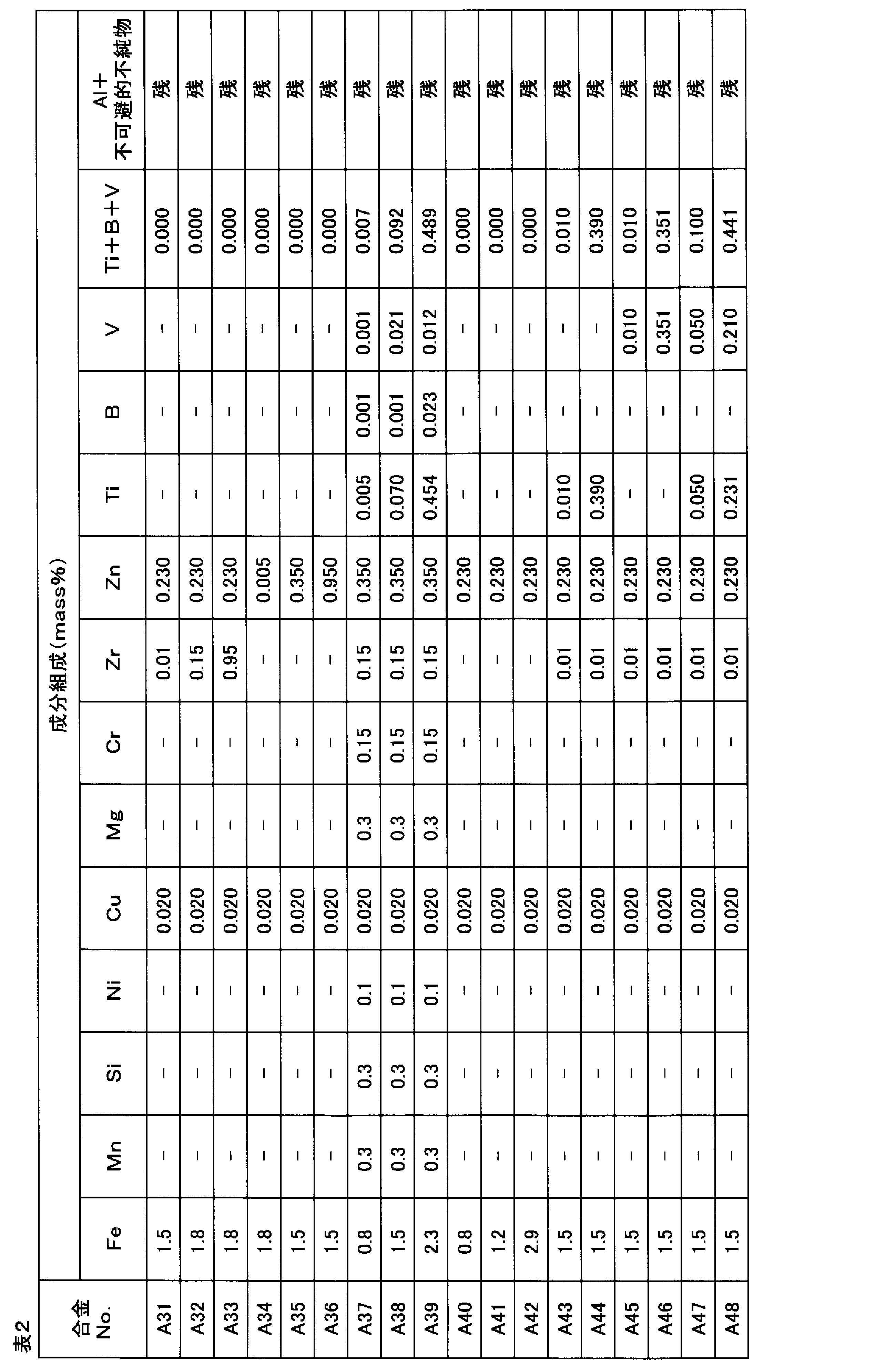

次に、No.A40~42及びAC1以外は、アルミニウム合金溶湯をDC法により鋳造し、厚さ400mmの鋳塊を作製してその両面を15mm面削した(ステップS102)。No.A40~42及びAC1は、アルミニウム合金溶湯をCC法により鋳造し、鋳塊を作製した。次に、面削したDC鋳塊に550℃で10時間の均質化熱処理を施した(ステップS103)。次に、均質化処理を施したDC鋳塊を熱間圧延開始温度540℃、熱間圧延終了温度200℃の条件で熱間圧延を行ない、熱間圧延板とした(ステップS104)。CC鋳塊の板厚と熱間圧延板の板厚を、冷間圧延前の板厚として表4~6に示す。
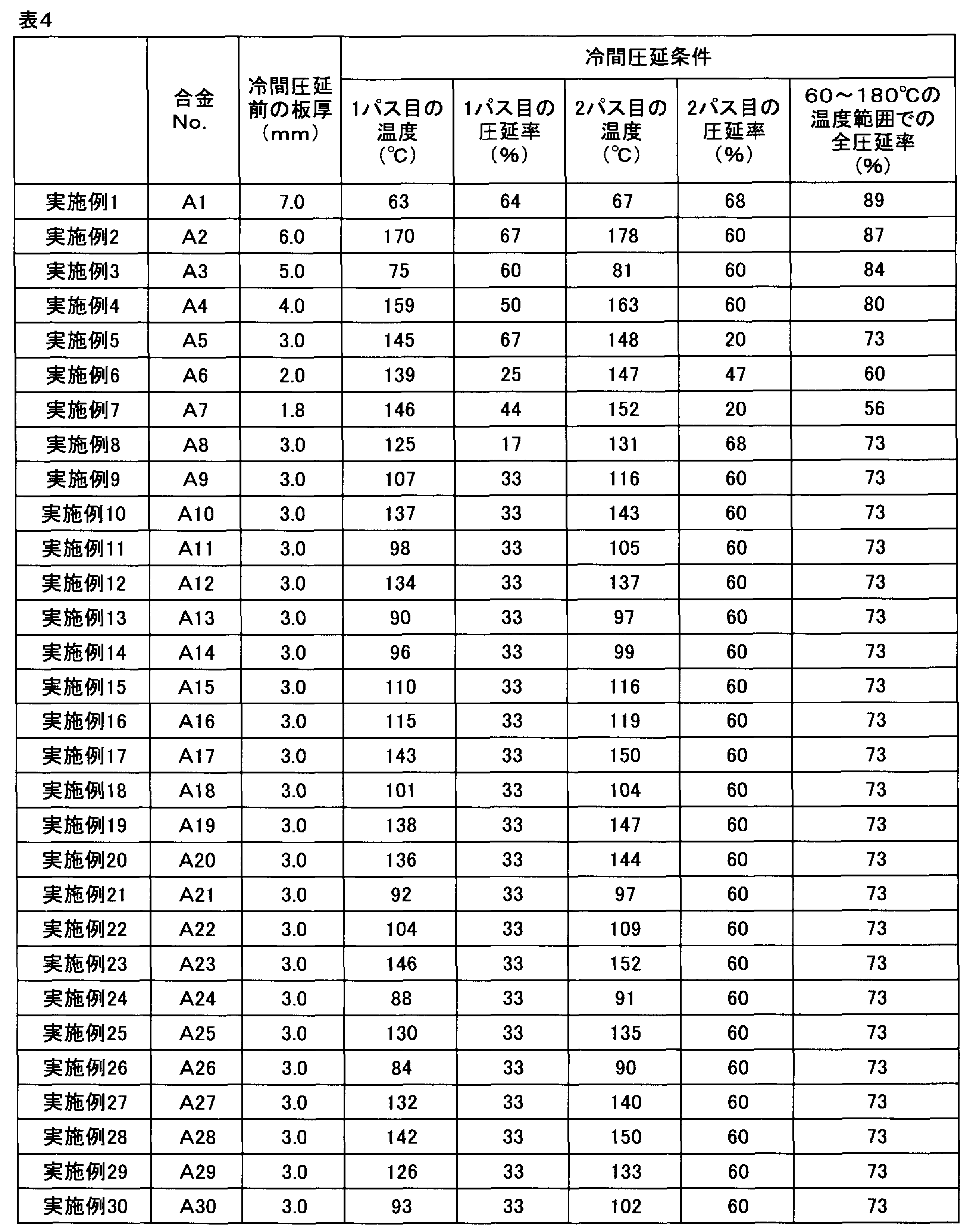
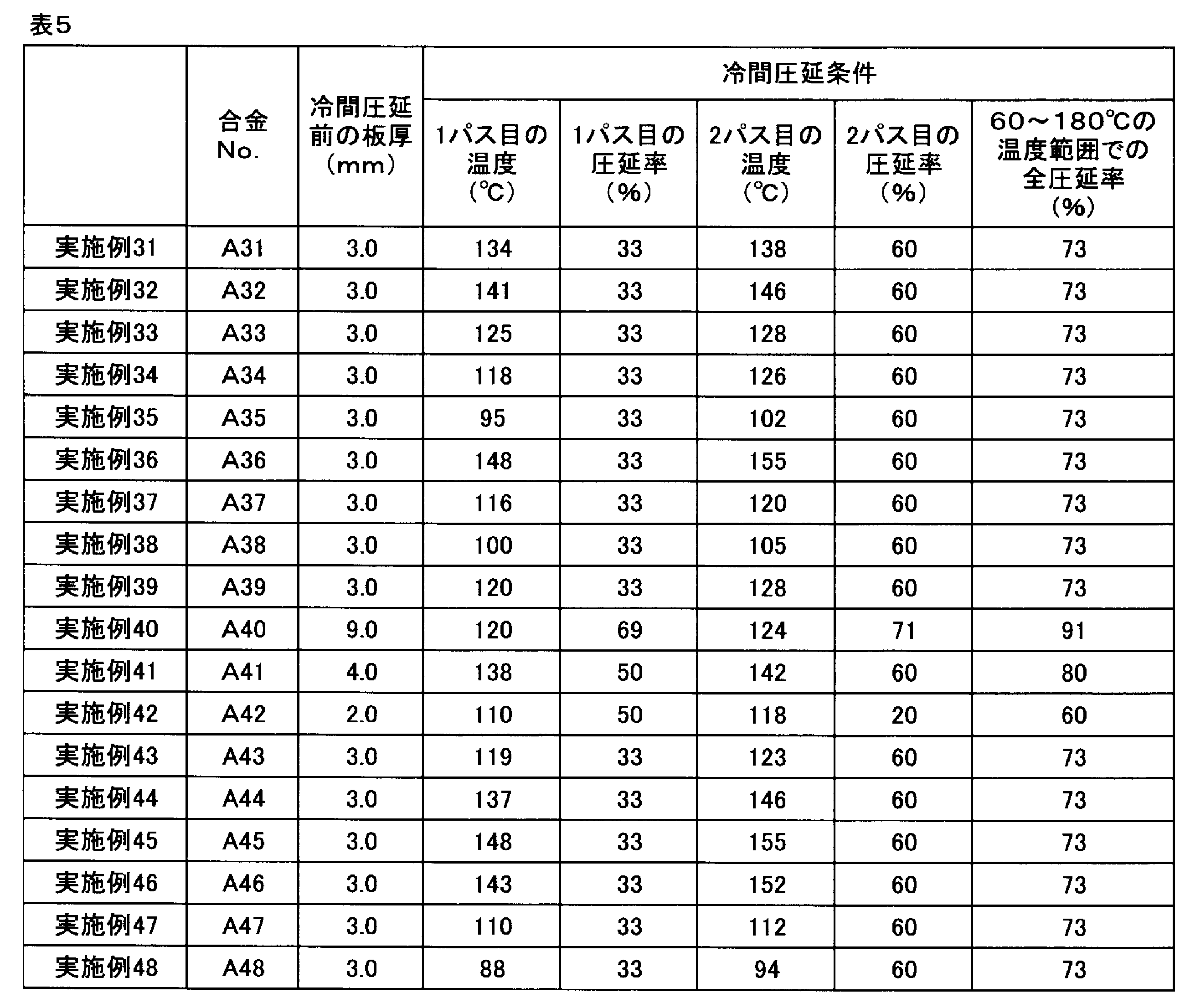
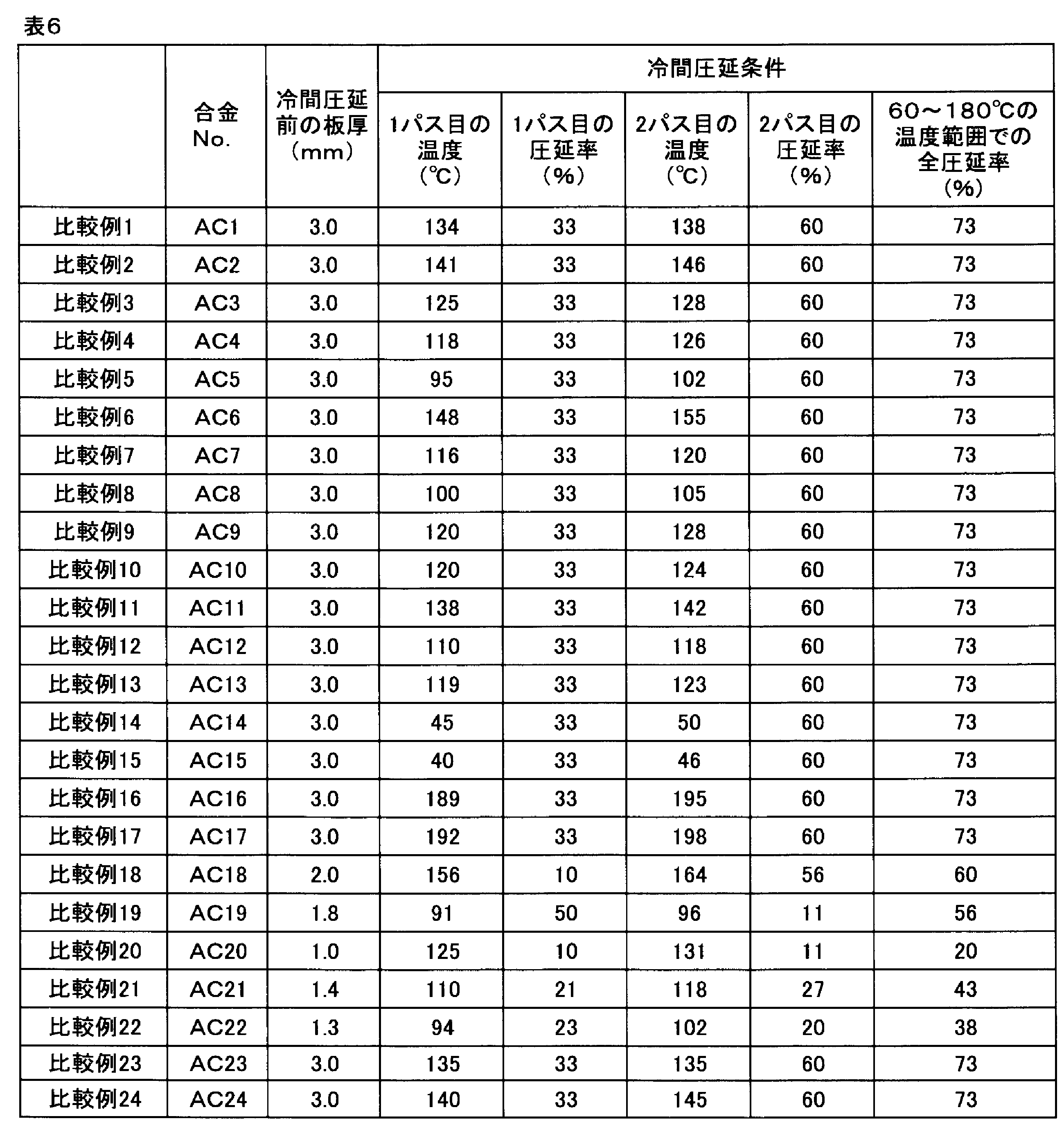
熱間圧延後のNo.A1、A3の熱間圧延板、ならびに、A40の鋳塊は、360℃で2時間の条件で焼鈍(バッチ式)処理を施した。以上のようにして作製した板材又は鋳塊は、冷間圧延により最終板厚の0.8mmまで圧延し、アルミニウム合金板とした(ステップS105)。冷間圧延の条件を表4~6に示す。このアルミニウム合金板から外径96mm、内径24mmの円環状のものを打抜き、ディスクブランクを作製した(ステップS106)。
このようにして作製したディスクブランクに、0.5MPaの圧力下において250℃で3時間の加圧平坦化処理を施した(ステップS107)。次いで、加圧平坦化処理したディスクブランクに端面加工を行い外径95mm、内径25mmとし、グラインディング加工(表面70μm研削)を行ってアルミニウム合金基板を作製した(ステップS108)。その後、AD-68F(商品名、上村工業製)により60℃で5分の脱脂を行った後、AD-107F(商品名、上村工業製)により65℃で1分の酸エッチングを行い、さらに30%HNO3水溶液(室温)で20秒間デスマットした(ステップS109)。
このようにして表面状態を整えた後に、ディスクブランクをAD-301F-3X(商品名、上村工業製)の20℃のジンケート処理液に0.5分間浸漬して表面にジンケート処理を施した(ステップS109)。なお、ジンケート処理は合計2回行い、ジンケート処理の間に室温の30%HNO3水溶液に20秒間浸漬して表面を剥離処理した。ジンケート処理した表面に無電解Ni-Pめっき処理液(ニムデンHDX(商品名、上村工業製))を用いてNi-Pを13.5μm厚さに無電解めっきした後、羽布により仕上げ研磨(研磨量3.1μm))を行って磁気ディスク基板ディスク用のアルミニウム合金基盤とした(ステップS110)。
研削加工(ステップS108)工程後のアルミニウム合金基板、ならびに、めっき処理研磨(ステップS110)工程後のアルミニウム合金基盤について以下の評価を行った。なお、比較例14と15では、冷間圧延後に表面に沿った割れが多数発生したため、以下の評価は行わなかった。また、各試料については、5枚のディスクをめっき処理まで実施しているが、比較例4~13のディスクでは、5枚全てでめっき剥離が生じていたため、ディスク・フラッタの測定を行うことが出来なかった。また、実施例10と42では5枚のうち3枚で、実施例15では5枚のうち2枚で、実施例20では5枚のうち3枚でめっき剥離が生じたが、めっき剥離が生じなかったものを用い評価を実施した。
〔Al-Fe系金属間化合物の分布密度〕
研削加工(ステップS108)後のアルミニウム合金基板表面を、光学顕微鏡により400倍の倍率で観察視野1mm2の範囲を観察し、粒子解析ソフトA像くん(商品名、旭化成エンジニアリング(株)社製)を用いて金属間化合物の最長径及び分布密度(個/mm2)の測定を行った。10μm以上16μm未満の最長径を有するAl-Fe系金属間化合物の分布密度Aと、10μm以上の最長径を有するAl-Fe系金属間化合物の分布密度Bと、それらの割合(A/B)と、40μm以上の最長径を有するAl-Fe系金属間化合物の分布密度を求めた。
研削加工(ステップS108)後のアルミニウム合金基板表面を、光学顕微鏡により400倍の倍率で観察視野1mm2の範囲を観察し、粒子解析ソフトA像くん(商品名、旭化成エンジニアリング(株)社製)を用いて金属間化合物の最長径及び分布密度(個/mm2)の測定を行った。10μm以上16μm未満の最長径を有するAl-Fe系金属間化合物の分布密度Aと、10μm以上の最長径を有するAl-Fe系金属間化合物の分布密度Bと、それらの割合(A/B)と、40μm以上の最長径を有するAl-Fe系金属間化合物の分布密度を求めた。
〔ディスク・フラッタの測定〕
めっき処理研磨(ステップS110)工程後のアルミニウム合金基盤を用いディスク・フラッタの測定を行った。ディスク・フラッタの測定は、市販のハードディスクドライブに空気の存在下、アルミニウム合金基盤を設置して測定を行った。ドライブはSeagate製ST2000(商品名)を用いて、モーター駆動はテクノアライブ製SLD102(商品名)をモーターに直結することにより駆動させた。回転数は7200rpmとし、ディスクは常に複数枚設置してその上部の磁気ディスクの表面にレーザードップラー計である小野測器製LDV1800(商品名)によって表面の振動を観察した。観察した振動は、小野測器製FFT解析装置DS3200(商品名)によってスペクトル分析した。観察はハードディスクドライブの蓋に孔を開けることにより、その穴からディスク表面を観察して行った。また、市販のハードディスクに設置されていたスクイーズプレートは外して評価を行った。
めっき処理研磨(ステップS110)工程後のアルミニウム合金基盤を用いディスク・フラッタの測定を行った。ディスク・フラッタの測定は、市販のハードディスクドライブに空気の存在下、アルミニウム合金基盤を設置して測定を行った。ドライブはSeagate製ST2000(商品名)を用いて、モーター駆動はテクノアライブ製SLD102(商品名)をモーターに直結することにより駆動させた。回転数は7200rpmとし、ディスクは常に複数枚設置してその上部の磁気ディスクの表面にレーザードップラー計である小野測器製LDV1800(商品名)によって表面の振動を観察した。観察した振動は、小野測器製FFT解析装置DS3200(商品名)によってスペクトル分析した。観察はハードディスクドライブの蓋に孔を開けることにより、その穴からディスク表面を観察して行った。また、市販のハードディスクに設置されていたスクイーズプレートは外して評価を行った。
フラッタリング特性の評価は、フラッタリングが現れる300~1500Hzの付近のブロードなピークの最大変位(ディスクフラッタリング(nm))によって行った。このブロードなピークはNRRO(Non-Repeatable Run Out)と呼ばれ、ヘッドの位置決め誤差に対して大きな影響があることがわかっている。フラッタリング特性の評価は、空気中にて、30nm以下の場合をA(優)、30nmを超えて40nm以下をB(良)、40nmを超えて50nm以下をC(可)、50nmより大きい場合はD(劣)とした。
〔下地処理した磁気ディスク用アルミニウム合金基板の平滑性〕
めっき処理研磨(ステップS110)工程後のアルミニウム合金基盤表面におけるピットの個数を求めた。SEMにより2000倍の倍率で観察視野を1mm2とし、最長径1.0μm以上5.0μm未満の大きさのピットの個数を計測し、単位面積当たりの個数(個数密度:個/mm2)を求めた。
めっき処理研磨(ステップS110)工程後のアルミニウム合金基盤表面におけるピットの個数を求めた。SEMにより2000倍の倍率で観察視野を1mm2とし、最長径1.0μm以上5.0μm未満の大きさのピットの個数を計測し、単位面積当たりの個数(個数密度:個/mm2)を求めた。
ここで、ピットの最長径とは、SEMで観測されるピットの平面画像において、まず、輪郭線上における一点と輪郭線上の他の点との距離の最大値を計測し、次に、この最大値を輪郭線上における全ての点について計測し、最後に、これら全最大値のうちから選択される最も大きなものをいう。また、ピットの最長径の下限は限定されるものではないが、最長径が1.0μm未満のものは観察されなかったので対象外とした。なお、1mm2の観察視野中にピットの全体が存在している場合は勿論、ピットの一部のみが観察されたものも一個として数えた。評価基準としては、ピットの個数密度が0個/mm2の場合をA(優)とし、1~7個/mm2の場合をB(良)とし、8個/mm2以上の場合をD(劣)とした。
以上の評価結果を、表7~9に示す。
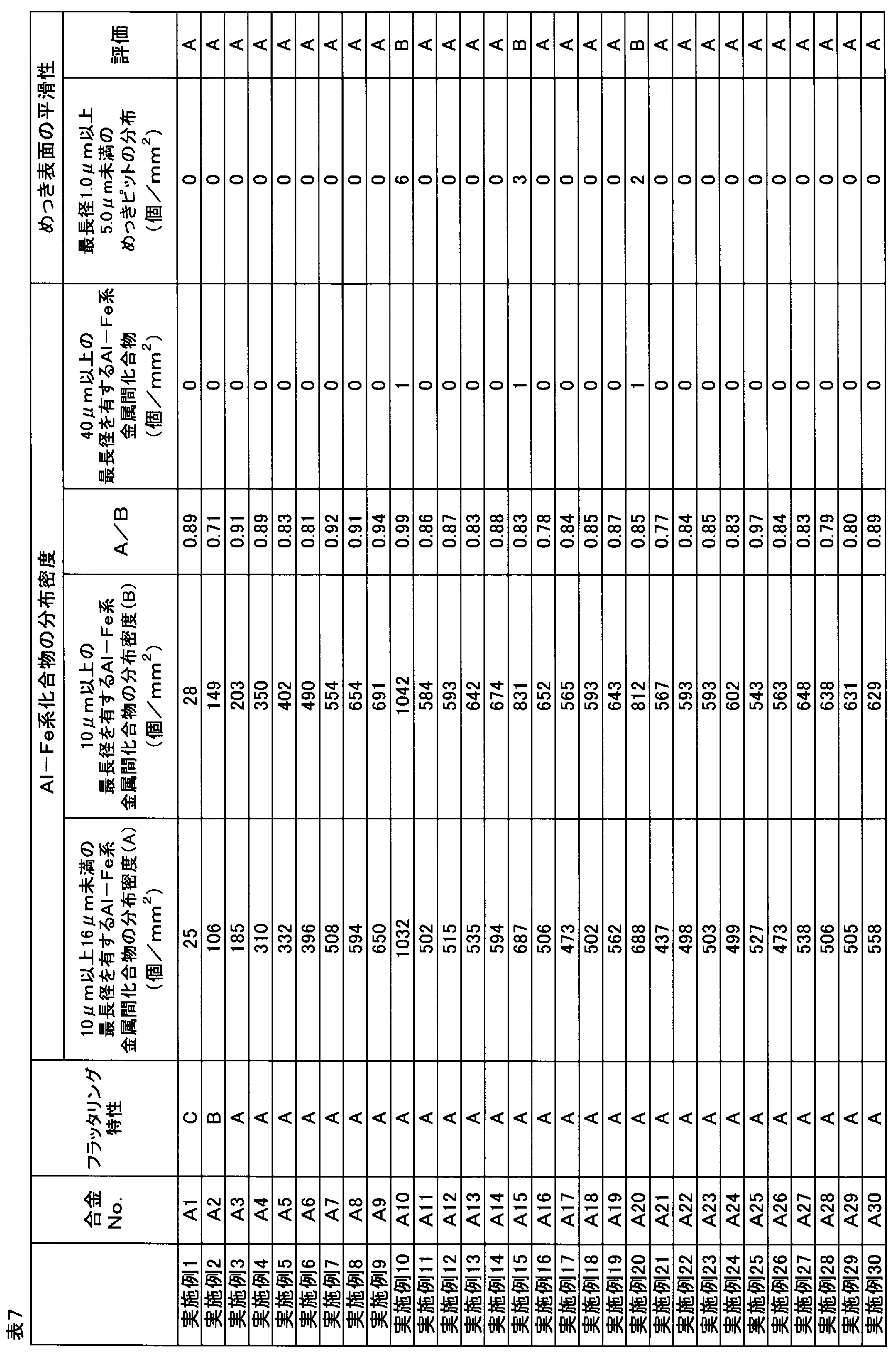


表7、8に示すように、実施例1~48では良好なめっき表面の平滑性とフラッタリング特性を得ることが出来た。
これに対して、比較例1~3では、アルミニウム合金のFe含有量が少な過ぎたために、フラッタリング特性が劣った。
比較例4、5では、アルミニウム合金のFe含有量が多過ぎたために先述の通りめっき剥離が生じ、フラッタリング特性が評価できず磁気ディスクとして不適であった。また、粗大な金属間化合物が多数存在したため、めっき表面にピットが多数発生し、めっき表面の平滑性が劣った。
比較例6では、アルミニウム合金のMn含有量が多過ぎたために先述の通りめっき剥離が生じ、フラッタリング特性が評価できず磁気ディスクとして不適であった。また、粗大な金属間化合物が多数存在したため、めっき表面にピットが多数発生し、めっき表面の平滑性が劣った。
比較例7では、アルミニウム合金のSi含有量が多過ぎたために先述の通りめっき剥離が生じ、フラッタリング特性が評価できず磁気ディスクとして不適であった。
比較例8では、アルミニウム合金のNi含有量が多過ぎたために先述の通りめっき剥離が生じ、フラッタリング特性が評価できず磁気ディスクとして不適であった。また、粗大な金属間化合物が多数存在したため、めっき表面にピットが多数発生し、めっき表面の平滑性が劣った。
比較例9では、アルミニウム合金のCu含有量が多過ぎたために先述の通りめっき剥離が生じ、フラッタリング特性が評価できず磁気ディスクとして不適であった。また、ジンケート性が不均一となり、めっき表面にピットが多数発生し、めっき表面の平滑性が劣った。
比較例10では、アルミニウム合金のMg含有量が多過ぎたために先述の通りめっき剥離が生じ、フラッタリング特性が評価できず磁気ディスクとして不適であった。
比較例11では、アルミニウム合金のCr含有量が多過ぎたために先述の通りめっき剥離が生じ、フラッタリング特性が評価できず磁気ディスクとして不適であった。また、粗大な金属間化合物が多数存在したため、めっき表面にピットが多数発生し、めっき表面の平滑性が劣った。
比較例12では、アルミニウム合金のZr含有量が多過ぎたために先述の通りめっき剥離が生じ、フラッタリング特性が評価できず磁気ディスクとして不適であった。また、粗大な金属間化合物が多数存在したため、めっき表面にピットが多数発生し、めっき表面の平滑性が劣った。
比較例13では、アルミニウム合金のZn含有量が多過ぎたために先述の通りめっき剥離が生じ、フラッタリング特性が評価できず磁気ディスクとして不適であった。また、ジンケート性が不均一となり、めっき表面にピットが多数発生し、めっき表面の平滑性が劣った。
比較例14、15では、冷間圧延時の温度が低過ぎたため、表面に割れが発生し、評価できず磁気ディスクとして不適であった。
比較例16、17では、冷間圧延時の温度が高過ぎたため、16μm以上の金属間化合物が多数存在し、A/Bが0.70未満となり、めっき表面にピットが多数発生し、めっき表面の平滑性が劣った。
比較例18では、冷間圧延時の1パス目の圧延率が低過ぎたため、また、比較例19では、冷間圧延時の2パス目の圧延率が低過ぎたため、いずれも16μm以上の金属間化合物が多数存在し、A/Bが0.70未満となり、めっき表面にピットが多数発生し、めっき表面の平滑性が劣った。
比較例20では、冷間圧延時の1パス目及び2パス目の圧延率、ならびに、全圧延率が低過ぎたため、16μm以上の金属間化合物が多数存在し、A/Bが0.70未満となり、めっき表面にピットが多数発生し、めっき表面の平滑性が劣った。
比較例21、22では、冷間圧延時での全圧延率が低過ぎたため、16μm以上の金属間化合物が多数存在し、A/Bが0.70未満となり、めっき表面にピットが多数発生し、めっき表面の平滑性が劣った。
比較例23では、アルミニウム合金のCu含有量が少な過ぎたために、ジンケート性が不均一となり、また、16μm以上の金属間化合物が多数存在してA/Bが0.70未満となり、めっき表面にピットが多数発生し、めっき表面の平滑性が劣った。
比較例24では、アルミニウム合金のZn含有量が少な過ぎたために、ジンケート性が不均一となり、また、16μm以上の金属間化合物が多数存在してA/Bが0.70未満となり、めっき表面にピットが多数発生し、めっき表面の平滑性が劣った。
本発明により、めっき性とディスクのフラッタリング特性に優れた磁気ディスク用アルミニウム合金基板及びその製造方法、ならびに、当該磁気ディスク用アルミニウム合金基板を用いた磁気ディスクが得られる。
Claims (7)
- Fe:0.4~3.0mass%、Cu:0.005~1.000mass%、Zn:0.005~1.000massを含有し、残部Al及び不可避不純物からなるアルミニウム合金からなり、10μm以上16μm未満の最長径を有するAl-Fe系金属間化合物の分布密度Aと10μm以上の最長径を有するAl-Fe系金属間化合物の分布密度Bの割合(A/B)が0.70以上で、40μm以上の最長径を有するAl-Fe系金属間化合物が1個/mm2以下の分布密度で分散することを特徴とする磁気ディスク用アルミニウム合金基板。
- 前記アルミニウム合金が、Mn:0.1~3.0mass%、Si:0.1~0.4mass%、Mg:0.1~0.4mass%、Ni:0.1~3.0mass%、Cr:0.01~1.00mass%及びZr:0.01~1.00mass%からなる群から選択される1種又は2種以上を更に含有する、請求項1に記載の磁気ディスク用アルミニウム合金基板。
- 前記アルミニウム合金が、含有量の合計が0.005~0.500mass%以下のTi、B及びVからなる群から選択される1種又は2種以上を更に含有する、請求項1又は2に記載の磁気ディスク用アルミニウム合金基板。
- 請求項1~3のいずれか一項に記載の磁気ディスク用アルミニウム合金基板の表面に、無電解Ni-Pめっき処理層とその上の磁性体層が設けられていることを特徴とする磁気ディスク。
- 請求項1~3のいずれか一項に記載される磁気ディスク用アルミニウム合金基板の製造方法であって、前記アルミニウム合金を用いて鋳塊を鋳造する鋳造工程と、鋳塊を冷間圧延する冷間圧延工程と、冷間圧延板を円環状に打ち抜くディスクブランク打抜き工程と、打ち抜いたディスクブランクを加圧焼鈍する加圧焼鈍工程と、加圧焼鈍したディスクブランクに切削加工と研削加工を施す切削・研削工程とを含み、前記冷間圧延工程において、60~180℃の温度範囲で1パス当たりの圧延率を15%以上とし、かつ、全圧延率を50%以上で冷間圧延することを特徴とする磁気ディスク用アルミニウム合金基板の製造方法。
- 前記鋳造工程と前記冷間圧延工程の間に、鋳造した鋳塊を280~620℃で0.5~60時間加熱処理する均質化熱処理工程と、均質化熱処理した鋳塊を250~600℃の開始温度と230~450℃の終了温度で熱間圧延する熱間圧延工程とを更に含む、請求項5に記載の磁気ディスク用アルミニウム合金基板の製造方法。
- 前記冷間圧延の前又は途中において、鋳塊又は圧延板を焼鈍する焼鈍処理工程であって、300~500℃で0.1~30時間のバッチ焼鈍処理工程、又は400~600℃で0~60秒の連続焼鈍処理工程を更に含む、請求項5又は6に記載の磁気ディスク用アルミニウム合金基板の製造方法。
Priority Applications (3)
| Application Number | Priority Date | Filing Date | Title |
|---|---|---|---|
| CN201980013742.9A CN111771241B (zh) | 2018-02-17 | 2019-02-06 | 磁盘用铝合金基板及其制造方法、以及使用该磁盘用铝合金基板的磁盘 |
| US16/969,847 US11037594B2 (en) | 2018-02-17 | 2019-02-06 | Aluminum-alloy substrate for magnetic disk, method for manufacturing same and magnetic disk employing said aluminum-alloy substrate for magnetic disk |
| MYPI2020004189A MY183251A (en) | 2018-02-17 | 2019-02-06 | Aluminum-alloy substrate for magnetic disk, method for manufacturing same and magnetic disk employing said aluminum-alloy substrate for magnetic disk |
Applications Claiming Priority (2)
| Application Number | Priority Date | Filing Date | Title |
|---|---|---|---|
| JP2018-026537 | 2018-02-17 | ||
| JP2018026537A JP6389577B1 (ja) | 2018-02-17 | 2018-02-17 | 磁気ディスク用アルミニウム合金基板及びその製造方法、ならびに、当該磁気ディスク用アルミニウム合金基板を用いた磁気ディスク |
Publications (1)
| Publication Number | Publication Date |
|---|---|
| WO2019159795A1 true WO2019159795A1 (ja) | 2019-08-22 |
Family
ID=63518834
Family Applications (1)
| Application Number | Title | Priority Date | Filing Date |
|---|---|---|---|
| PCT/JP2019/004294 Ceased WO2019159795A1 (ja) | 2018-02-17 | 2019-02-06 | 磁気ディスク用アルミニウム合金基板及びその製造方法、ならびに、当該磁気ディスク用アルミニウム合金基板を用いた磁気ディスク |
Country Status (5)
| Country | Link |
|---|---|
| US (1) | US11037594B2 (ja) |
| JP (1) | JP6389577B1 (ja) |
| CN (1) | CN111771241B (ja) |
| MY (1) | MY183251A (ja) |
| WO (1) | WO2019159795A1 (ja) |
Families Citing this family (7)
| Publication number | Priority date | Publication date | Assignee | Title |
|---|---|---|---|---|
| JP6506897B1 (ja) | 2018-10-15 | 2019-04-24 | 株式会社Uacj | 磁気ディスク用アルミニウム合金板及びその製造方法、ならびに、当該磁気ディスク用アルミニウム合金板を用いた磁気ディスク |
| JP7145731B2 (ja) * | 2018-11-08 | 2022-10-03 | 古河電気工業株式会社 | 磁気ディスク用ブランク材及びその製造方法 |
| JP7132289B2 (ja) * | 2019-12-09 | 2022-09-06 | 株式会社神戸製鋼所 | 磁気ディスク用アルミニウム合金板、磁気ディスク用アルミニウム合金ブランク、磁気ディスク用アルミニウム合金サブストレート、及び磁気ディスク用アルミニウム合金板の製造方法 |
| JP6857279B1 (ja) * | 2020-10-22 | 2021-04-14 | 株式会社Uacj | 薄型基板内蔵ハードディスクドライブ及び薄型基板内蔵ハードディスクドライブ用ベースプレート部材 |
| CN113751682A (zh) * | 2021-08-12 | 2021-12-07 | 西安鼎鑫科技新材料有限公司 | 一种车用铸造超高强铝合金轮毂材料铸造工艺及设备 |
| CN114855025B (zh) * | 2022-04-28 | 2024-04-30 | 山东博源精密机械有限公司 | 一种利用回收铝制备电机转子铝合金的方法和应用 |
| CN118641424B (zh) * | 2024-08-14 | 2025-02-07 | 崇义章源钨业股份有限公司 | 一种表征硬质合金毛坯密度分布的方法 |
Citations (2)
| Publication number | Priority date | Publication date | Assignee | Title |
|---|---|---|---|---|
| JP2013112884A (ja) * | 2011-11-30 | 2013-06-10 | Furukawa-Sky Aluminum Corp | アルミニウム合金基板及びその製造方法 |
| JP2017031507A (ja) * | 2015-07-28 | 2017-02-09 | 株式会社Uacj | 磁気ディスク用アルミニウム合金基板及びその製造方法 |
Family Cites Families (9)
| Publication number | Priority date | Publication date | Assignee | Title |
|---|---|---|---|---|
| JPH10102177A (ja) * | 1996-09-30 | 1998-04-21 | Furukawa Electric Co Ltd:The | 高容量磁気ディスク基板用アルミニウム合金クラッド板およびその製造方法 |
| JP3983005B2 (ja) | 2001-04-13 | 2007-09-26 | 富士通株式会社 | 磁気ディスク装置 |
| JP4646192B2 (ja) * | 2004-06-02 | 2011-03-09 | 古河電気工業株式会社 | 電気電子機器用銅合金材料およびその製造方法 |
| JP4764459B2 (ja) * | 2008-08-28 | 2011-09-07 | 株式会社神戸製鋼所 | 裏面白化防止性に優れる印刷版用高強度アルミニウム合金板 |
| KR20110096120A (ko) * | 2008-12-19 | 2011-08-29 | 후루카와 덴키 고교 가부시키가이샤 | 전기전자 부품용 동합금재 및 그 제조방법 |
| CN101851715A (zh) * | 2009-03-31 | 2010-10-06 | 株式会社神户制钢所 | 电池外壳用铝合金板及电池外壳 |
| JP5973952B2 (ja) * | 2013-04-19 | 2016-08-23 | 株式会社神戸製鋼所 | 磁気ディスク用アルミニウム合金基板およびその製造方法 |
| TWI604065B (zh) * | 2013-05-25 | 2017-11-01 | Uacj Corp | Battery case aluminum alloy plate and its manufacturing method |
| MY182369A (en) | 2014-10-31 | 2021-01-21 | Uacj Corp | Aluminum alloy substrate for magnetic disk |
-
2018
- 2018-02-17 JP JP2018026537A patent/JP6389577B1/ja not_active Expired - Fee Related
-
2019
- 2019-02-06 MY MYPI2020004189A patent/MY183251A/en unknown
- 2019-02-06 US US16/969,847 patent/US11037594B2/en not_active Expired - Fee Related
- 2019-02-06 WO PCT/JP2019/004294 patent/WO2019159795A1/ja not_active Ceased
- 2019-02-06 CN CN201980013742.9A patent/CN111771241B/zh not_active Expired - Fee Related
Patent Citations (2)
| Publication number | Priority date | Publication date | Assignee | Title |
|---|---|---|---|---|
| JP2013112884A (ja) * | 2011-11-30 | 2013-06-10 | Furukawa-Sky Aluminum Corp | アルミニウム合金基板及びその製造方法 |
| JP2017031507A (ja) * | 2015-07-28 | 2017-02-09 | 株式会社Uacj | 磁気ディスク用アルミニウム合金基板及びその製造方法 |
Also Published As
| Publication number | Publication date |
|---|---|
| JP6389577B1 (ja) | 2018-09-12 |
| CN111771241A (zh) | 2020-10-13 |
| CN111771241B (zh) | 2021-12-24 |
| US11037594B2 (en) | 2021-06-15 |
| US20200381015A1 (en) | 2020-12-03 |
| MY183251A (en) | 2021-02-18 |
| JP2019143178A (ja) | 2019-08-29 |
Similar Documents
| Publication | Publication Date | Title |
|---|---|---|
| JP6389546B1 (ja) | 磁気ディスク用アルミニウム合金基板及びその製造方法、ならびに、この磁気ディスク用アルミニウム合金基板を用いた磁気ディスク | |
| JP6389577B1 (ja) | 磁気ディスク用アルミニウム合金基板及びその製造方法、ならびに、当該磁気ディスク用アルミニウム合金基板を用いた磁気ディスク | |
| JP6402229B1 (ja) | 磁気ディスク用アルミニウム合金基板及びその製造方法、ならびに、当該磁気ディスク用アルミニウム合金基板を用いた磁気ディスク | |
| JP6437583B2 (ja) | 磁気ディスク基板用アルミニウム合金板及びその製造方法、ならびに、この磁気ディスク基板用アルミニウム合金板を用いた磁気ディスク | |
| JP6439082B1 (ja) | アルミニウム合金製の磁気ディスク基板及びその製造方法 | |
| WO2016068293A1 (ja) | 磁気ディスク用アルミニウム合金基板 | |
| WO2017188320A1 (ja) | 磁気ディスク用基板 | |
| JP6492219B1 (ja) | 磁気ディスク用アルミニウム合金基板及びその製造方法、ならびに、当該磁気ディスク用アルミニウム合金基板を用いた磁気ディスク | |
| CN111448611A (zh) | 磁盘用铝合金基板及其制造方法、以及使用了该磁盘用铝合金基板的磁盘 | |
| JP6998499B1 (ja) | 磁気ディスク用アルミニウム合金基板、ならびに、当該磁気ディスク用アルミニウム合金基板を用いた磁気ディスク | |
| CN112840399B (zh) | 磁盘用铝合金板及其制造方法,以及使用该磁盘用铝合金板的磁盘 | |
| JP6492218B1 (ja) | 磁気ディスク用アルミニウム合金板及びその製造方法、ならびに、この磁気ディスク用アルミニウム合金板を用いた磁気ディスク | |
| JP2019167601A (ja) | 磁気ディスク用アルミニウム合金板及びその製造方法、ならびに、当該磁気ディスク用アルミニウム合金板を用いた磁気ディスク | |
| JP6492216B1 (ja) | 磁気ディスク用アルミニウム合金基板及びその製造方法、ならびに、当該磁気ディスク用アルミニウム合金基板を用いた磁気ディスク | |
| JP2017166017A (ja) | 磁気ディスク用アルミニウム合金基板 |
Legal Events
| Date | Code | Title | Description |
|---|---|---|---|
| 121 | Ep: the epo has been informed by wipo that ep was designated in this application |
Ref document number: 19754108 Country of ref document: EP Kind code of ref document: A1 |
|
| NENP | Non-entry into the national phase |
Ref country code: DE |
|
| 122 | Ep: pct application non-entry in european phase |
Ref document number: 19754108 Country of ref document: EP Kind code of ref document: A1 |