WO2019150941A1 - 動力伝達系の耐久寿命管理装置および動力伝達系の耐久寿命管理方法 - Google Patents
動力伝達系の耐久寿命管理装置および動力伝達系の耐久寿命管理方法 Download PDFInfo
- Publication number
- WO2019150941A1 WO2019150941A1 PCT/JP2019/000984 JP2019000984W WO2019150941A1 WO 2019150941 A1 WO2019150941 A1 WO 2019150941A1 JP 2019000984 W JP2019000984 W JP 2019000984W WO 2019150941 A1 WO2019150941 A1 WO 2019150941A1
- Authority
- WO
- WIPO (PCT)
- Prior art keywords
- degree
- power transmission
- transmission system
- fatigue
- damage
- Prior art date
- Legal status (The legal status is an assumption and is not a legal conclusion. Google has not performed a legal analysis and makes no representation as to the accuracy of the status listed.)
- Ceased
Links
Images


Classifications
-
- G—PHYSICS
- G07—CHECKING-DEVICES
- G07C—TIME OR ATTENDANCE REGISTERS; REGISTERING OR INDICATING THE WORKING OF MACHINES; GENERATING RANDOM NUMBERS; VOTING OR LOTTERY APPARATUS; ARRANGEMENTS, SYSTEMS OR APPARATUS FOR CHECKING NOT PROVIDED FOR ELSEWHERE
- G07C5/00—Registering or indicating the working of vehicles
- G07C5/08—Registering or indicating performance data other than driving, working, idle, or waiting time, with or without registering driving, working, idle or waiting time
- G07C5/0816—Indicating performance data, e.g. occurrence of a malfunction
-
- F—MECHANICAL ENGINEERING; LIGHTING; HEATING; WEAPONS; BLASTING
- F16—ENGINEERING ELEMENTS AND UNITS; GENERAL MEASURES FOR PRODUCING AND MAINTAINING EFFECTIVE FUNCTIONING OF MACHINES OR INSTALLATIONS; THERMAL INSULATION IN GENERAL
- F16H—GEARING
- F16H59/00—Control inputs to control units of change-speed- or reversing-gearings for conveying rotary motion
- F16H59/14—Inputs being a function of torque or torque demand
-
- F—MECHANICAL ENGINEERING; LIGHTING; HEATING; WEAPONS; BLASTING
- F16—ENGINEERING ELEMENTS AND UNITS; GENERAL MEASURES FOR PRODUCING AND MAINTAINING EFFECTIVE FUNCTIONING OF MACHINES OR INSTALLATIONS; THERMAL INSULATION IN GENERAL
- F16H—GEARING
- F16H57/00—General details of gearing
- F16H57/01—Monitoring wear or stress of gearing elements, e.g. for triggering maintenance
-
- F—MECHANICAL ENGINEERING; LIGHTING; HEATING; WEAPONS; BLASTING
- F16—ENGINEERING ELEMENTS AND UNITS; GENERAL MEASURES FOR PRODUCING AND MAINTAINING EFFECTIVE FUNCTIONING OF MACHINES OR INSTALLATIONS; THERMAL INSULATION IN GENERAL
- F16H—GEARING
- F16H59/00—Control inputs to control units of change-speed- or reversing-gearings for conveying rotary motion
- F16H59/36—Inputs being a function of speed
-
- F—MECHANICAL ENGINEERING; LIGHTING; HEATING; WEAPONS; BLASTING
- F16—ENGINEERING ELEMENTS AND UNITS; GENERAL MEASURES FOR PRODUCING AND MAINTAINING EFFECTIVE FUNCTIONING OF MACHINES OR INSTALLATIONS; THERMAL INSULATION IN GENERAL
- F16H—GEARING
- F16H59/00—Control inputs to control units of change-speed- or reversing-gearings for conveying rotary motion
- F16H59/60—Inputs being a function of ambient conditions
- F16H59/66—Road conditions, e.g. slope, slippery
Definitions
- the present disclosure relates to a power transmission system durability life management apparatus and a power transmission system durability life management method.
- Patent Document 1 describes a technique for quantitatively determining the state of an engine or transmission.
- a load state applied to an engine or a transmission is detected by a torque sensor, a vehicle speed sensor, or the like, and the state of the engine or transmission is determined based on an accumulated time or the like when the detected load value is larger than a predetermined threshold value. Is determined quantitatively.
- Patent Document 1 is mainly intended to use the determination result of the state of the engine or transmission as vehicle evaluation information such as vehicle price information. Although it is described that the determination result of the state of the engine or transmission is used as a determination material for inspecting or maintaining the vehicle, it is not described specifically how to use it.
- An object of the present disclosure is to provide a power transmission system durable life management apparatus and a power transmission system durable life management method capable of appropriately managing the durability life by estimating the degree of fatigue of the power transmission system.
- An endurance life management device for a power transmission system includes an input unit that receives an input of vehicle travel information including torque generated by a drive source, and damage to power transmission system components based on the travel information.
- a control unit that calculates a degree of fatigue based on the degree of damage, and indicates that the degree of fatigue is high when the degree of fatigue is determined to be high.
- An output unit for outputting a signal.
- a method for managing a durable life of a power transmission system includes a step of receiving an input of vehicle travel information including torque generated by a drive source, and a damage degree of components of the power transmission system based on the travel information. And determining whether the power transmission system has a high degree of fatigue based on the degree of damage and a signal indicating that the degree of fatigue is high when the degree of fatigue is determined to be high. Outputting.
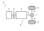
- FIG. 1 is a schematic diagram showing an outline of a power transmission system of a vehicle.
- FIG. 2 is a block diagram illustrating an outline of a durable life management device for a power transmission system according to an embodiment of the present disclosure.
- FIG. 3 is a diagram illustrating an example of a torque frequency table stored in the storage unit.
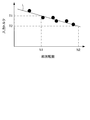
- FIG. 4 is a diagram illustrating an example of the relationship between the torque applied to the member and the durability life.
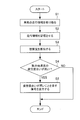
- FIG. 5 is a flowchart illustrating an example of processing performed by the control unit.
- the vehicle 1 includes an engine 3, a clutch 4, a transmission 5, a propeller shaft 6, a final reduction gear 7, drive shafts 8 and 8, and drive wheels 9 and 9.
- the transmission 5 to the final reduction gear 7 are referred to as the power transmission system 2.
- the drive source of the vehicle 1 is not limited to the engine 3, and the power transmission system 2 is not limited to the transmission 5, the propeller shaft 6, and the final reduction gear 7.
- the durable life management apparatus 20 includes an input unit 21, a control unit 22, an output unit 23, and a storage unit 24.
- the input unit 21 receives input of engine rotation speed information from the engine rotation sensor 11, engine output torque information from the engine output torque sensor 12, time information from the timer 13, and shift position information from the shift position sensor 14. .
- the control unit 22 evaluates the degree of fatigue of each member of the power transmission system 2 based on the engine rotational speed information, engine output torque information, time information, and shift position information input to the input unit 21.
- the output unit 23 outputs a notification signal to the notification unit 30 based on the evaluation result in the control unit 22.
- the storage unit 24 stores various data used when the control unit 22 evaluates the degree of fatigue of each member of the power transmission system 2.
- FIG. 3 shows an example of a torque frequency table as an example of data stored in the storage unit 24.
- the torque frequency table shown in FIG. 3 is prepared for each gear position.
- time is accumulated for any combination of engine rotation speed and shaft torque (engine output torque). That is, the storage unit 24 stores what gear stage, engine output torque and engine rotation speed the vehicle 1 has traveled.
- the shaft torque is shown as a percentage with respect to the maximum output torque of the engine 3.
- FIG. 3 shows that, for example, a state where the engine rotational speed is 0 to Ne 1 (rpm) and the shaft torque is 0 to Te 1 (%) is S 11 (sec). Further, for example, indicates that the engine rotational speed state Ne m-1 ⁇ Ne m ( rpm) and the shaft torque is Te n-1 ⁇ Te n ( %) had S mn (sec). Note that m and n are natural numbers.
- FIG. 4 shows an example of the relationship between the torque applied to a predetermined member and the durability life.
- the vertical axis and horizontal axis in FIG. 4 are both logarithmic displays. Such a relationship can be obtained by experiments.
- the black circles in FIG. 4 are plots of the total number of revolutions at which the member is broken when the member is rotated by applying a predetermined torque. Actually, for all members to be evaluated, the relationship between the torque applied to the member and the durable life is obtained in advance by experiments.
- a straight line L in FIG. 4 is created based on a plurality of black circles (for example, six black circles in FIG. 4), and indicates a predicted value of the durable life of the member.
- the durable life of the member is N1
- the durable life of the member is N2.
- the straight line L in FIG. 4 can be expressed by the following formula (1) using the torque T, the rotational speed N, and the constants A and B.
- the storage unit 24 stores the constant B in the above equation (1) for all the parts to be evaluated.
- the control unit 22 calculates the damage degree (times) of each member using, for example, the following equation (2).
- the above equation (2) is a conversion equation for converting what is loaded with various torques to a predetermined member various times to how many times the predetermined assumed torque (constant) is loaded.
- the shaft torque (%), the engine speed (rpm), and the time (sec) in the equation (2) are parameters in FIG. 3 described above.
- the engine maximum torque is a value that varies depending on the type of the engine 3 mounted on the vehicle 1 and is stored in the storage unit 24 in advance.
- the assumed torque may be stored in advance in the storage unit 24 or may be determined when the control unit 22 calculates the damage level.
- the gear ratio is a gear ratio from the engine 3 to a predetermined member to be evaluated, and is stored in the storage unit 24 in advance. Such a gear ratio varies depending on a predetermined member to be evaluated. Further, it varies depending on the model and specification of the transmission 5, the specification of the final reduction gear 7, and the like.
- the gear ratio from the engine 3 to a predetermined member to be evaluated is different for each gear position in the transmission 5.
- a damage degree is calculated for every gear stage, and the total damage degree can be calculated
- the control unit 22 When the damage degree of any member among the damage degrees of the respective members thus obtained reaches a predetermined value indicating that the durability life in the assumed torque has been approached (in other words, the control unit 22). When a predetermined ratio is reached with respect to the endurance life in the assumed torque), it is determined that the degree of fatigue of the power transmission system 2 has increased, and a signal is output to the output unit 23. Such a predetermined value (predetermined ratio) can be determined in consideration of the usage mode of the vehicle 1 and the safety factor.
- the notification unit 30 is, for example, an instrument panel or the like of the vehicle 1 and displays on the instrument panel or the like that the degree of fatigue of the power transmission system 2 has increased.
- the notification unit 30 may be an alarm or the like.
- the flowchart shown in FIG. 5 is repeatedly executed at a predetermined cycle while the vehicle 1 is traveling.
- step S1 the control unit 22 receives travel information of the vehicle 1 such as engine rotation speed information, engine output torque information, time information, and shift position information input to the input unit 21.
- travel information of the vehicle 1 such as engine rotation speed information, engine output torque information, time information, and shift position information input to the input unit 21.
- step S ⁇ b> 2 the control unit 22 stores the travel information received from the input unit 21 in the storage unit 24.
- step S ⁇ b> 3 the control unit 22 calculates the damage degree for each member of the power transmission system 2 based on the information stored in the storage unit 24.
- step S4 the control unit 22 determines whether the degree of fatigue of the power transmission system 2 is high.
- step S4 If it is determined in step S4 that the degree of fatigue of the power transmission system 2 is high (step S4: YES), the process proceeds to step S5.
- step S5 the control unit 22 outputs a signal indicating that the degree of fatigue of the power transmission system 2 is high to the output unit 23, and ends the process.
- step S4 determines whether the degree of fatigue of the power transmission system 2 is high (step S4: NO). If it is not determined in step S4 that the degree of fatigue of the power transmission system 2 is high (step S4: NO), the control unit 22 indicates that the degree of fatigue of the power transmission system 2 is higher than that of the output unit 23. The processing is terminated without outputting the indicated signal.
- the input unit 21 that receives the input of the vehicle travel information including the torque generated by the drive source, and the damage degree of the components of the power transmission system are calculated based on the travel information.
- a control unit 22 for determining whether the power transmission system has a high degree of fatigue based on the damage level, and a signal indicating that the fatigue level is high when the fatigue level is determined to be high.
- An endurance life management device 20 including an output unit 23 for outputting is provided.
- Modification of notification timing A modification of the notification timing will be described.
- the notification timing first, as described above, when the damage level reaches a predetermined value indicating that it has approached the endurance life, or when the damage level reaches a predetermined ratio with respect to the endurance life, There is a mode in which it is judged that the degree of fatigue of the transmission system is high and notification is made.
- the threshold value for determining that the degree of fatigue of the power transmission system is high can be changed according to the usage mode of the vehicle.
- the usage mode of the vehicle may vary greatly depending on the driver. For example, if there is a driver that uses the travel time t1 (or travel distance d1) so that the degree of damage reaches about half of the durability life, the travel time t2 (> t1) (or travel distance d2 (> d1)) Some drivers use it in such a way that the damage is about half of its endurance life.
- the damage level reaches about half of the endurance life at the travel time t1 (or travel distance d1)
- the damage level reaches about half the endurance life at the travel time t2 (or travel distance d2).
- the above-described predetermined value or predetermined ratio may be changed based on the degree of change in the degree of damage with respect to a predetermined travel time or travel distance. By doing so, notification can be performed at an appropriate timing regardless of the usage mode of the vehicle, and the durable life can be appropriately managed. Note that “about half” is merely an example and is not limited thereto.
- the notification timing can be changed in consideration of the remaining life. For example, when it is continuously used in the most recent vehicle usage mode, the predetermined value indicating that the damage level is approaching the endurance life or the remaining time (or remaining distance) until reaching the endurance life is the predetermined margin time (or margin) When the distance is less than (distance), it may be determined that the degree of fatigue of the power transmission system is high and notification may be made.
- the remaining time until the damage level reaches the above-mentioned predetermined value or a predetermined ratio is estimated, and the remaining time is determined in advance. If it is shorter, the degree of fatigue may be determined to be high. By doing so, notification can be performed at an appropriate timing regardless of the usage mode of the vehicle, and the durable life can be appropriately managed.
- a modified example of the notification target will be described.
- a notification target first, as described above, a driver who is driving a vehicle may be used. In this case, it is possible to directly notify the driver who is driving the vehicle that the degree of fatigue of the power transmission system has increased.
- a predetermined device is connected to the durable life management device, and a signal notifying that the degree of fatigue of the power transmission system has increased from the durable life management device to the predetermined device. It may be. By doing so, it is possible to replace the members of the power transmission system at an appropriate timing.
- Modification of damage level calculation method A modification of the damage level calculation method will be described.
- a calculation method of the damage level first, as described above, there is a method of converting various torques applied to the member into a predetermined assumed torque.
- the total engine speed is calculated from the engine speed and time.
- the present invention is not limited to this.
- the total engine speed may be directly detected.
- the durability life of the power transmission system can be appropriately managed, and industrial applicability is great.
Landscapes
- Engineering & Computer Science (AREA)
- General Engineering & Computer Science (AREA)
- Mechanical Engineering (AREA)
- Physics & Mathematics (AREA)
- General Physics & Mathematics (AREA)
- Control Of Transmission Device (AREA)
- Testing Of Devices, Machine Parts, Or Other Structures Thereof (AREA)
Abstract
動力伝達系の疲労度合いを推定して耐久寿命を適切に管理すべく、動力伝達系の耐久寿命管理装置は、駆動源が発生するトルクを含む車両の走行情報の入力を受け付ける入力部と、前記走行情報に基づいて動力伝達系の部品の被害度を算出し、前記被害度に基づいて前記動力伝達系の疲労度合いが高いか否かを判断する制御部と、前記疲労度合いが高いと判断された場合に、前記疲労度合いが高いことを示す信号を出力する出力部と、を備える。
Description
本開示は、動力伝達系の耐久寿命管理装置および動力伝達系の耐久寿命管理方法に関する。
特許文献1には、エンジンやトランスミッションの状態を定量的に判断する技術が記載されている。特許文献1では、エンジンやトランスミッションにかかる負荷状態がトルクセンサや車速センサ等によって検出され、検出された負荷の値が予め定められた閾値よりも大きいときの累積時間等から、エンジンやトランスミッションの状態が定量的に判断される。
特許文献1の技術は、エンジンやトランスミッションの状態の判断結果を車両価格情報等の車両評価情報に用いることを主目的としている。なお、エンジンやトランスミッションの状態の判断結果を車両の点検や整備を行うための判断材料として使用することも記載されているが、具体的にどのように用いるかについては記載されていない。
本開示の目的は、動力伝達系の疲労度合いを推定して耐久寿命を適切に管理することができる動力伝達系の耐久寿命管理装置および動力伝達系の耐久寿命管理方法を提供することである。
本開示の一態様に係る動力伝達系の耐久寿命管理装置は、駆動源が発生するトルクを含む車両の走行情報の入力を受け付ける入力部と、前記走行情報に基づいて動力伝達系の部品の被害度を算出し、前記被害度に基づいて前記動力伝達系の疲労度合いが高いか否かを判断する制御部と、前記疲労度合いが高いと判断された場合に、前記疲労度合いが高いことを示す信号を出力する出力部と、を備える。
本開示の一態様に係る動力伝達系の耐久寿命管理方法は、駆動源が発生するトルクを含む車両の走行情報の入力を受け付けるステップと、前記走行情報に基づいて動力伝達系の部品の被害度を算出し、前記被害度に基づいて前記動力伝達系の疲労度合いが高いか否かを判断するステップと、前記疲労度合いが高いと判断された場合に、前記疲労度合いが高いことを示す信号を出力するステップと、を備える。
上記の態様によれば、動力伝達系の耐久寿命を適切に管理することができる。
以下、本開示の実施形態について、図面を参照して詳細に説明する。なお、以下に説明する実施形態は一例であり、本開示はこの実施形態により限定されるものではない。
まず、図1を参照して、車両1の動力伝達系2の概略について説明する。車両1は、エンジン3と、クラッチ4と、変速機5と、プロペラシャフト6と、終減速機7と、ドライブシャフト8、8と、駆動輪9、9とを有する。以下の説明では、変速機5から終減速機7までを、動力伝達系2という。なお、車両1の駆動源はエンジン3には限定されず、動力伝達系2についても変速機5、プロペラシャフト6および終減速機7には限定されない。
次に、図2を参照して、車両1に搭載される耐久寿命管理装置20の概略について説明する。耐久寿命管理装置20は、入力部21、制御部22、出力部23および記憶部24を有する。
入力部21は、エンジン回転センサ11からのエンジン回転速度情報、エンジン出力トルクセンサ12からのエンジン出力トルク情報、計時タイマ13からの時間情報、およびシフトポジションセンサ14からのシフトポジション情報の入力を受け付ける。
制御部22は、入力部21に入力されたエンジン回転速度情報、エンジン出力トルク情報、時間情報およびシフトポジション情報に基づいて、動力伝達系2の各部材の疲労度合いを評価する。
出力部23は、制御部22における評価結果に基づいて、報知部30に報知信号を出力する。
記憶部24は、制御部22において動力伝達系2の各部材の疲労度合いを評価する際に用いられる各種データを記憶する。
図3に、記憶部24に記憶されているデータの一例としてのトルク頻度テーブルの一例を示す。図3に示すトルク頻度テーブルは、変速段ごとに用意されている。図3に示すように、トルク頻度テーブルでは、エンジン回転速度および軸トルク(エンジン出力トルク)の任意の組み合わせに対して、時間が累積される。すなわち、記憶部24には、車両1が如何なるギヤ段、エンジン出力トルクおよびエンジン回転速度で走行したかが記憶されることになる。なお、図3では、軸トルクは、エンジン3の最大出力トルクに対する百分率で示されている。
図3では、例えば、エンジン回転速度が0~Ne1(rpm)かつ軸トルクが0~Te1(%)である状態がS11(sec)あったことを示している。また、例えば、エンジン回転速度がNem-1~Nem(rpm)かつ軸トルクがTen-1~Ten(%)である状態がSmn(sec)あったことを示している。なお、mおよびnは自然数である。
図4に、所定の部材に負荷されるトルクと耐久寿命との関係の一例を示す。図4における縦軸および横軸は共に対数表示である。このような関係は実験により求められる。図4における黒丸は、所定の部材に対して所定のトルクを負荷して回転させた場合に、当該部材が破断した総回転数をプロットしたものである。実際には、評価対象となる全ての部材に対して、実験により部材に負荷されるトルクと耐久寿命との関係が予め求められている。
図4における直線Lは、複数の黒丸(例えば、図4では6個の黒丸)に基づいて作成されたものであり、部材の耐久寿命の予測値を示す。図4に示す例では、部材に対する入力トルクがT1であれば、部材の耐久寿命がN1であり、部材に対する入力トルクがT2であれば、部材の耐久寿命がN2であることを示している。なお、図4における直線Lは、トルクT、回転数N、定数AおよびBを用いて、以下の式(1)で表すことができる。

記憶部24には、評価対象となる全ての部品について、上述の式(1)における定数Bが記憶されている。制御部22は、例えば、以下の式(2)を用いて、各部材の被害度(回)を算出する。

上述の式(2)は、所定の部材に対して様々なトルクが様々な回数負荷されたものを、所定の仮定トルク(一定)が何回負荷されたかに変換する変換式である。式(2)中の軸トルク(%)、エンジン回転速度(rpm)および時間(sec)は、上述の図3における各パラメータである。
なお、図3では、軸トルクおよびエンジン回転速度として所定の幅をもった値を採用しているため、式(2)に用いる軸トルクおよびエンジン回転数として、当該所定の幅における最大値や平均値を用いるようにすることもできる。
エンジン最大トルクは、車両1に搭載されるエンジン3の種類によって異なる値であり、予め記憶部24に記憶されている。仮定トルクについては、予め記憶部24に記憶されていてもよいし、制御部22において被害度を算出する際に決定されてもよい。
また、ギヤ比は、エンジン3から評価対象である所定の部材までのギヤ比であり、予め記憶部24に記憶されている。このようなギヤ比は、評価対象である所定の部材によって異なる。さらに、変速機5の機種や仕様、終減速機7の仕様等によっても異なる。
また、例えば、終減速機7の構成部品については、変速機5における変速段ごとにエンジン3から評価対象である所定の部材までのギヤ比が異なる。このような部材については、被害度を変速段ごとに算出し、それらを加算することで総被害度を求めることができる。
制御部22は、このようにして求めた各部材の被害度のうち、いずれかの部材の被害度が、仮定トルクにおける耐久寿命に近づいたことを示す所定値に達した場合に(換言すれば、仮定トルクにおける耐久寿命に対して所定割合に達した場合に)、動力伝達系2の疲労度合いが高くなったと判断し、出力部23に対して信号を出力する。このような所定値(所定割合)は、車両1の使用態様や安全率等を考慮して定めることができる。
報知部30は、例えば車両1のインストルメントパネル等であり、動力伝達系2の疲労度合いが高くなったことを、インストルメントパネル等に表示させる。なお、報知部30はアラーム等でもよい。
次に、制御部22において行われる処理について、図5のフローチャートを参照して説明する。図5に示すフローチャートは、車両1の走行中に所定の周期で繰り返し実行される。
まず、ステップS1で、制御部22は、入力部21に入力されたエンジン回転速度情報、エンジン出力トルク情報、時間情報、シフトポジション情報等の、車両1の走行情報を受け取る。
続くステップS2で、制御部22は、入力部21から受け取った走行情報を記憶部24に記憶させる。
続くステップS3で、制御部22は、記憶部24に記憶された情報に基づいて、動力伝達系2の各部材のそれぞれについて、被害度を算出する。
続くステップS4で、制御部22は、動力伝達系2の疲労度合いが高いか否かを判断する。
ステップS4で、動力伝達系2の疲労度合いが高いと判断された場合(ステップS4:YES)、処理はステップS5に進む。そして、ステップS5で、制御部22は、出力部23に対して、動力伝達系2の疲労度合いが高いことを示す信号を出力し、処理を終了する。
一方、ステップS4で、動力伝達系2の疲労度合いが高いと判断されなかった場合(ステップS4:NO)、制御部22は、出力部23に対して動力伝達系2の疲労度合いが高いことを示す信号を出力することなく、処理を終了する。
以上説明したように、本実施形態によれば、駆動源が発生するトルクを含む車両の走行情報の入力を受け付ける入力部21と、前記走行情報に基づいて動力伝達系の部品の被害度を算出し、前記被害度に基づいて前記動力伝達系の疲労度合いが高いか否かを判断する制御部22と、前記疲労度合いが高いと判断された場合に、前記疲労度合いが高いことを示す信号を出力する出力部23と、を備える耐久寿命管理装置20が提供される。
これにより、動力伝達系の各部材の被害度を定量的に算出して、動力伝達系の疲労度合いが高くなったことをドライバ等に対して報知することができる。そのため、動力伝達系の耐久寿命を適切に管理することができる。
(報知タイミングの変形例)
報知タイミングの変形例について説明する。報知タイミングとしては、第一に、上述したように、被害度が耐久寿命に近づいたことを示す所定値に達した場合や、被害度が耐久寿命に対して所定割合に達した場合に、動力伝達系の疲労度合いが高いと判断し、報知を行う態様がある。
報知タイミングの変形例について説明する。報知タイミングとしては、第一に、上述したように、被害度が耐久寿命に近づいたことを示す所定値に達した場合や、被害度が耐久寿命に対して所定割合に達した場合に、動力伝達系の疲労度合いが高いと判断し、報知を行う態様がある。
第二に、車両の使用態様に応じて、動力伝達系の疲労度合いが高いと判断する閾値を変更することができる。車両の使用態様は、ドライバによって大きく異なる場合がある。例えば、走行時間t1(または走行距離d1)で被害度が耐久寿命の半分程度に達するような使い方をするドライバもいれば、走行時間t2(>t1)(または走行距離d2(>d1))で被害度が耐久寿命の半分程度に達するような使い方をするドライバもいる。
走行時間t1(または走行距離d1)で被害度が耐久寿命の半分程度に達した場合と、走行時間t2(または走行距離d2)で被害度が耐久寿命の半分程度に達した場合とでは、その後、耐久寿命に達するまでの期間が異なる。
そのため、走行時間t1(または走行距離d1)で被害度が耐久寿命の半分程度に達した場合には、走行時間t2(または走行距離d2)で被害度が耐久寿命の半分程度に達した場合よりも被害度が低いタイミングで動力伝達系の疲労度合いが高いと判断してもよい。
すなわち、所定の走行時間または走行距離に対する被害度の変化の度合いに基づいて、上述の所定値や所定割合を変更してもよい。こうすることで、車両の使用態様の如何にかかわらず、適切なタイミングで報知を行うことができ、耐久寿命を適切に管理することができる。なお、「半分程度」はあくまでも例示に過ぎず、これに限定されない。
第三に、残り寿命を考慮して報知タイミングを変更することができる。例えば、直近の車両の使用態様で引き続き使用した場合に、被害度が耐久寿命に近づいたことを示す所定値や耐久寿命に達するまでの残時間(または残距離)が所定の余裕時間(または余裕距離)を下回った場合に、動力伝達系の疲労度合いが高いと判断して報知を行うようにしてもよい。
すなわち、所定の走行時間または走行距離に対する被害度の変化の度合いに基づいて、被害度が上述の所定値や所定割合に達するまでの残時間を推定し、当該残時間が予め定められた余裕時間よりも短い場合に、疲労度合いが高いと判断してもよい。こうすることで、車両の使用態様の如何にかかわらず、適切なタイミングで報知を行うことができ、耐久寿命を適切に管理することができる。
(報知対象の変形例)
報知対象の変形例について説明する。報知対象としては、第一に、上述したように、車両を運転しているドライバが挙げられる。この場合、動力伝達系の疲労度合いが高くなったことを、車両を運転しているドライバに直接報知することができる。
報知対象の変形例について説明する。報知対象としては、第一に、上述したように、車両を運転しているドライバが挙げられる。この場合、動力伝達系の疲労度合いが高くなったことを、車両を運転しているドライバに直接報知することができる。
第二に、車両が管理者によって管理されている場合には、動力伝達系の疲労度合いが高くなったことを、管理者に対して報知することができる。具体的には、管理者に対して無線通信等を介して動力伝達系の疲労度合いが高くなったことを報知することができる。こうすることで、管理者が車両の状態を適切に把握することができる。
第三に、車両の整備を行うディーラー等に対して、動力伝達系の疲労度合いが高くなったことを報知することができる。この場合、第二の例と同様に、無線通信等を用いて動力伝達系の疲労度合いが高くなったことを報知することができる。
また、整備を行うタイミングで、所定の装置を耐久寿命管理装置に接続し、耐久寿命管理装置から当該所定の装置に対して動力伝達系の疲労度合いが高くなったことを知らせる信号を出力するようにしてもよい。こうすることで、動力伝達系の部材の交換等を適切なタイミングで行うことができる。
(被害度の算出方法の変形例)
被害度の算出方法の変形例について説明する。被害度の算出方法としては、第一に、上述したように、部材に負荷される様々なトルクを所定の仮定トルクに変換する方法が挙げられる。
被害度の算出方法の変形例について説明する。被害度の算出方法としては、第一に、上述したように、部材に負荷される様々なトルクを所定の仮定トルクに変換する方法が挙げられる。
第二に、部材に負荷される様々なトルクのそれぞれについて、当該トルクにおける疲労寿命に対する被害度(回)の割合を算出し、それらを加算することで被害割合を算出する方法が挙げられる。この場合、疲労寿命の実験結果が存在するトルクについては、疲労寿命に対する被害割合をより正確に算出することができ、有用である。
(その他の変形例)
上述の実施形態では、エンジン回転速度と時間からエンジンの総回転数を算出する構成としたが、これに限定されない。例えば、エンジンの総回転数を直接検出するようにしてもよい。
上述の実施形態では、エンジン回転速度と時間からエンジンの総回転数を算出する構成としたが、これに限定されない。例えば、エンジンの総回転数を直接検出するようにしてもよい。
本出願は、2018年1月31日付で出願された日本国特許出願(特願2018-015613)に基づくものであり、その内容はここに参照として取り込まれる。
本開示の動力伝達系の耐久寿命管理装置および動力伝達系の耐久寿命管理方法によれば、動力伝達系の耐久寿命を適切に管理することができ、産業上の利用可能性は多大である。
1 車両
2 動力伝達系
3 エンジン
4 クラッチ
5 変速機
6 プロペラシャフト
7 終減速機
8 ドライブシャフト
9 駆動輪
11 エンジン回転センサ
12 エンジン出力トルクセンサ
13 計時タイマ
14 シフトポジションセンサ
20 耐久寿命管理装置
21 入力部
22 制御部
23 出力部
24 記憶部
30 報知部
2 動力伝達系
3 エンジン
4 クラッチ
5 変速機
6 プロペラシャフト
7 終減速機
8 ドライブシャフト
9 駆動輪
11 エンジン回転センサ
12 エンジン出力トルクセンサ
13 計時タイマ
14 シフトポジションセンサ
20 耐久寿命管理装置
21 入力部
22 制御部
23 出力部
24 記憶部
30 報知部
Claims (5)
- 駆動源が発生するトルクを含む車両の走行情報の入力を受け付ける入力部と、
前記走行情報に基づいて動力伝達系の部品の被害度を算出し、前記被害度に基づいて前記動力伝達系の疲労度合いが高いか否かを判断する制御部と、
前記疲労度合いが高いと判断された場合に、前記疲労度合いが高いことを示す信号を出力する出力部と、を備える
動力伝達系の耐久寿命管理装置。 - 前記制御部は、前記被害度が予め定められた所定値に達した場合に、前記疲労度合いが高いと判断する
請求項1に記載の動力伝達系の耐久寿命管理装置。 - 前記制御部は、所定の走行時間または走行距離に対する前記被害度の変化の度合いに基づいて、前記所定値を変更する
請求項2に記載の動力伝達系の耐久寿命管理装置。 - 前記制御部は、所定の走行時間または走行距離に対する前記被害度の変化の度合いに基づいて、前記被害度が予め定められた所定値に達するまでの残時間を推定し、前記残時間が予め定められた余裕時間よりも短い場合に、前記疲労度合いが高いと判断する
請求項1に記載の動力伝達系の耐久寿命管理装置。 - 駆動源が発生するトルクを含む車両の走行情報の入力を受け付けるステップと、
前記走行情報に基づいて動力伝達系の部品の被害度を算出し、前記被害度に基づいて前記動力伝達系の疲労度合いが高いか否かを判断するステップと、
前記疲労度合いが高いと判断された場合に、前記疲労度合いが高いことを示す信号を出力するステップと、を備える
動力伝達系の耐久寿命管理方法。
Priority Applications (3)
| Application Number | Priority Date | Filing Date | Title |
|---|---|---|---|
| DE112019000602.9T DE112019000602T5 (de) | 2018-01-31 | 2019-01-16 | Dauerhaltbarkeitsverwaltungsvorrichtung eines kraftübertragungssystems und dauerhaltbarkeitsverwaltungsverfahren eines kraftübertragungssystems |
| US16/965,677 US12046088B2 (en) | 2018-01-31 | 2019-01-16 | Durability life management device of power transmission system and durability life management method of power transmission system |
| CN201980010859.1A CN111670316B (zh) | 2018-01-31 | 2019-01-16 | 动力传递系统的耐久寿命管理装置及动力传递系统的耐久寿命管理方法 |
Applications Claiming Priority (2)
| Application Number | Priority Date | Filing Date | Title |
|---|---|---|---|
| JP2018015613A JP7059657B2 (ja) | 2018-01-31 | 2018-01-31 | 動力伝達系の耐久寿命管理装置および動力伝達系の耐久寿命管理方法 |
| JP2018-015613 | 2018-01-31 |
Publications (1)
| Publication Number | Publication Date |
|---|---|
| WO2019150941A1 true WO2019150941A1 (ja) | 2019-08-08 |
Family
ID=67478752
Family Applications (1)
| Application Number | Title | Priority Date | Filing Date |
|---|---|---|---|
| PCT/JP2019/000984 Ceased WO2019150941A1 (ja) | 2018-01-31 | 2019-01-16 | 動力伝達系の耐久寿命管理装置および動力伝達系の耐久寿命管理方法 |
Country Status (5)
| Country | Link |
|---|---|
| US (1) | US12046088B2 (ja) |
| JP (1) | JP7059657B2 (ja) |
| CN (1) | CN111670316B (ja) |
| DE (1) | DE112019000602T5 (ja) |
| WO (1) | WO2019150941A1 (ja) |
Cited By (2)
| Publication number | Priority date | Publication date | Assignee | Title |
|---|---|---|---|---|
| US20210248843A1 (en) * | 2020-02-07 | 2021-08-12 | Toyota Jidosha Kabushiki Kaisha | Vehicle diagnostic system |
| US12046088B2 (en) | 2018-01-31 | 2024-07-23 | Isuzu Motors Limited | Durability life management device of power transmission system and durability life management method of power transmission system |
Families Citing this family (3)
| Publication number | Priority date | Publication date | Assignee | Title |
|---|---|---|---|---|
| JP7533332B2 (ja) | 2021-04-15 | 2024-08-14 | トヨタ自動車株式会社 | ドライブシャフトの疲労損傷度の推定装置 |
| JP7622539B2 (ja) | 2021-04-28 | 2025-01-28 | トヨタ自動車株式会社 | 疲労推定装置、余寿命推定システムおよび疲労推定方法 |
| CN115451121B (zh) * | 2022-10-13 | 2023-10-27 | 同济大学 | 考虑齿轮寿命的变速器自调整均衡换档策略 |
Citations (5)
| Publication number | Priority date | Publication date | Assignee | Title |
|---|---|---|---|---|
| JP2003346010A (ja) * | 2002-05-29 | 2003-12-05 | Honda Motor Co Ltd | サービス提供システム |
| JP2004243924A (ja) * | 2003-02-14 | 2004-09-02 | Fujitsu Ten Ltd | 車両劣化評価装置 |
| JP2004293629A (ja) * | 2003-03-26 | 2004-10-21 | Jatco Ltd | ロックアップクラッチの寿命判定方法及び寿命判定装置 |
| JP2013079920A (ja) * | 2011-10-05 | 2013-05-02 | Mitsubishi Motors Corp | 車両の疲労損傷度診断システム |
| JP2015003722A (ja) * | 2013-06-19 | 2015-01-08 | ローベルト ボッシュ ゲゼルシャフト ミット ベシュレンクテル ハフツング | 特に自動車を経年劣化・エネルギー効率的に作動させる方法 |
Family Cites Families (15)
| Publication number | Priority date | Publication date | Assignee | Title |
|---|---|---|---|---|
| US6225892B1 (en) * | 1999-04-15 | 2001-05-01 | Meritor Heavy Vehicle Systems, Llc | Gear fatigue monitor |
| US6526816B2 (en) * | 2000-12-13 | 2003-03-04 | Eaton Corporation | Transmission gear life monitor system |
| JP4134672B2 (ja) | 2002-10-18 | 2008-08-20 | 株式会社デンソー | 車両用制御システム |
| US7195575B2 (en) * | 2004-03-22 | 2007-03-27 | General Motors Corporation | Splined sun gear and method for compact electro-mechanical transmission |
| JP2007239802A (ja) * | 2006-03-06 | 2007-09-20 | Toyota Motor Corp | 環状伝動体の疲労警告システム |
| US7852201B2 (en) * | 2007-03-15 | 2010-12-14 | Gm Global Technology Operations, Inc. | Apparatus and method for determining the remaining useful life of a transmission filter |
| CN102944422B (zh) * | 2012-12-13 | 2015-01-21 | 重庆理工大学 | 汽车传动系统行驶载荷疲劳再现试验方法 |
| JP5816966B2 (ja) | 2013-03-04 | 2015-11-18 | ジヤトコ株式会社 | 摩擦締結要素の耐久寿命管理方法 |
| JP5909205B2 (ja) | 2013-03-21 | 2016-04-26 | ジヤトコ株式会社 | 摩擦締結要素の耐久寿命管理方法 |
| US20150134189A1 (en) | 2013-11-08 | 2015-05-14 | Ricardo, Inc. | Systems and methods for remaining useful life predictions in drivetrains |
| US9558600B2 (en) * | 2014-08-01 | 2017-01-31 | Deere & Company | Duty cycle recording system and method for estimation of damage and remaining life of drivetrain components |
| JP6582484B2 (ja) * | 2015-03-26 | 2019-10-02 | いすゞ自動車株式会社 | 走行制御装置、及び、走行制御方法 |
| JP6369501B2 (ja) * | 2016-05-19 | 2018-08-08 | マツダ株式会社 | 自動変速機の制御方法及び制御装置 |
| CN107020937A (zh) * | 2017-05-19 | 2017-08-08 | 北京理工华创电动车技术有限公司 | 一种双电机无动力中断变速装置及控制方法 |
| JP7059657B2 (ja) | 2018-01-31 | 2022-04-26 | いすゞ自動車株式会社 | 動力伝達系の耐久寿命管理装置および動力伝達系の耐久寿命管理方法 |
-
2018
- 2018-01-31 JP JP2018015613A patent/JP7059657B2/ja active Active
-
2019
- 2019-01-16 CN CN201980010859.1A patent/CN111670316B/zh active Active
- 2019-01-16 DE DE112019000602.9T patent/DE112019000602T5/de active Pending
- 2019-01-16 WO PCT/JP2019/000984 patent/WO2019150941A1/ja not_active Ceased
- 2019-01-16 US US16/965,677 patent/US12046088B2/en active Active
Patent Citations (5)
| Publication number | Priority date | Publication date | Assignee | Title |
|---|---|---|---|---|
| JP2003346010A (ja) * | 2002-05-29 | 2003-12-05 | Honda Motor Co Ltd | サービス提供システム |
| JP2004243924A (ja) * | 2003-02-14 | 2004-09-02 | Fujitsu Ten Ltd | 車両劣化評価装置 |
| JP2004293629A (ja) * | 2003-03-26 | 2004-10-21 | Jatco Ltd | ロックアップクラッチの寿命判定方法及び寿命判定装置 |
| JP2013079920A (ja) * | 2011-10-05 | 2013-05-02 | Mitsubishi Motors Corp | 車両の疲労損傷度診断システム |
| JP2015003722A (ja) * | 2013-06-19 | 2015-01-08 | ローベルト ボッシュ ゲゼルシャフト ミット ベシュレンクテル ハフツング | 特に自動車を経年劣化・エネルギー効率的に作動させる方法 |
Cited By (3)
| Publication number | Priority date | Publication date | Assignee | Title |
|---|---|---|---|---|
| US12046088B2 (en) | 2018-01-31 | 2024-07-23 | Isuzu Motors Limited | Durability life management device of power transmission system and durability life management method of power transmission system |
| US20210248843A1 (en) * | 2020-02-07 | 2021-08-12 | Toyota Jidosha Kabushiki Kaisha | Vehicle diagnostic system |
| CN113306560A (zh) * | 2020-02-07 | 2021-08-27 | 丰田自动车株式会社 | 车辆诊断系统 |
Also Published As
| Publication number | Publication date |
|---|---|
| DE112019000602T5 (de) | 2020-11-12 |
| US12046088B2 (en) | 2024-07-23 |
| JP2019132358A (ja) | 2019-08-08 |
| US20210043014A1 (en) | 2021-02-11 |
| JP7059657B2 (ja) | 2022-04-26 |
| CN111670316B (zh) | 2023-07-18 |
| CN111670316A (zh) | 2020-09-15 |
Similar Documents
| Publication | Publication Date | Title |
|---|---|---|
| JP7059657B2 (ja) | 動力伝達系の耐久寿命管理装置および動力伝達系の耐久寿命管理方法 | |
| CN111868416B (zh) | 动力传递部件的疲劳程度推断装置及动力传递部件的疲劳程度推断方法 | |
| CN107036807B (zh) | 用于测量全车轮驱动车辆的离合器寿命的方法和装置 | |
| EP2805854B1 (en) | Economical driving gear confirmation method for engine-driven vehicle | |
| JP5267095B2 (ja) | 走行状態評価装置 | |
| CN110023600A (zh) | 油更换时期判定装置 | |
| CN105083290B (zh) | 在能量域中的车辆能量消耗效率学习 | |
| CN102224362B (zh) | 档位反馈系统 | |
| US10336402B2 (en) | Method and device for operating an electric bicycle | |
| KR20240166002A (ko) | 차량 토크 제어 방법 및 장치, 전자 디바이스, 및 저장 매체 | |
| JP7310699B2 (ja) | オイル状態推定装置、車両用制御装置、車両用制御システム、およびデータ解析装置 | |
| CN115723707B (zh) | 一种车辆除雪方法、装置、车辆及电子设备 | |
| CN113771856B (zh) | 车辆的控制方法、装置、设备及介质 | |
| JP2005180643A (ja) | トルク伝達系の制御装置 | |
| JP2004225903A (ja) | 駆動システムの摩擦係合トルクを伝達する2つの構成部材間の接触圧力を設定するための方法及び装置 | |
| CN114719018A (zh) | 一种amt变速箱的控制方法、装置、计算机设备和存储介质 | |
| CN113060147A (zh) | 一种判断车辆打滑的方法、系统及车辆 | |
| CN113942492B (zh) | 混合动力车辆的驱动控制方法、装置及混合动力车辆 | |
| JP2010284050A (ja) | 走行制御装置、および該装置を備えたフォークリフト | |
| US20250289437A1 (en) | Method and sensor arrangement for determining an adverse condition of a powertrain | |
| RU2794446C1 (ru) | Способ и система интеллектуального управления полным приводом, а также транспортное средство | |
| CN118876734A (zh) | 齿轮传动系统控制方法、装置、设备、存储介质及产品 | |
| SE538585C2 (sv) | Förfarande och styranordning för att fastställa ett målvarvtal för en växling | |
| CN120292248A (zh) | 用于运行机动车辆的驱动系的方法和控制器以及机动车辆 | |
| KR20120133525A (ko) | 차량의 주행 도로 경사도 학습 장치 및 방법 |
Legal Events
| Date | Code | Title | Description |
|---|---|---|---|
| 121 | Ep: the epo has been informed by wipo that ep was designated in this application |
Ref document number: 19746987 Country of ref document: EP Kind code of ref document: A1 |
|
| 122 | Ep: pct application non-entry in european phase |
Ref document number: 19746987 Country of ref document: EP Kind code of ref document: A1 |