WO2019150855A1 - 空気入りタイヤ - Google Patents
空気入りタイヤ Download PDFInfo
- Publication number
- WO2019150855A1 WO2019150855A1 PCT/JP2018/047683 JP2018047683W WO2019150855A1 WO 2019150855 A1 WO2019150855 A1 WO 2019150855A1 JP 2018047683 W JP2018047683 W JP 2018047683W WO 2019150855 A1 WO2019150855 A1 WO 2019150855A1
- Authority
- WO
- WIPO (PCT)
- Prior art keywords
- groove
- tire
- closed
- width direction
- circumferential
- Prior art date
- Legal status (The legal status is an assumption and is not a legal conclusion. Google has not performed a legal analysis and makes no representation as to the accuracy of the status listed.)
- Ceased
Links
Images






Classifications
-
- B—PERFORMING OPERATIONS; TRANSPORTING
- B60—VEHICLES IN GENERAL
- B60C—VEHICLE TYRES; TYRE INFLATION; TYRE CHANGING; CONNECTING VALVES TO INFLATABLE ELASTIC BODIES IN GENERAL; DEVICES OR ARRANGEMENTS RELATED TO TYRES
- B60C11/00—Tyre tread bands; Tread patterns; Anti-skid inserts
- B60C11/03—Tread patterns
- B60C11/12—Tread patterns characterised by the use of narrow slits or incisions, e.g. sipes
-
- B—PERFORMING OPERATIONS; TRANSPORTING
- B60—VEHICLES IN GENERAL
- B60C—VEHICLE TYRES; TYRE INFLATION; TYRE CHANGING; CONNECTING VALVES TO INFLATABLE ELASTIC BODIES IN GENERAL; DEVICES OR ARRANGEMENTS RELATED TO TYRES
- B60C11/00—Tyre tread bands; Tread patterns; Anti-skid inserts
- B60C11/03—Tread patterns
- B60C11/0304—Asymmetric patterns
-
- B—PERFORMING OPERATIONS; TRANSPORTING
- B60—VEHICLES IN GENERAL
- B60C—VEHICLE TYRES; TYRE INFLATION; TYRE CHANGING; CONNECTING VALVES TO INFLATABLE ELASTIC BODIES IN GENERAL; DEVICES OR ARRANGEMENTS RELATED TO TYRES
- B60C11/00—Tyre tread bands; Tread patterns; Anti-skid inserts
- B60C11/03—Tread patterns
- B60C11/13—Tread patterns characterised by the groove cross-section, e.g. for buttressing or preventing stone-trapping
-
- B—PERFORMING OPERATIONS; TRANSPORTING
- B60—VEHICLES IN GENERAL
- B60C—VEHICLE TYRES; TYRE INFLATION; TYRE CHANGING; CONNECTING VALVES TO INFLATABLE ELASTIC BODIES IN GENERAL; DEVICES OR ARRANGEMENTS RELATED TO TYRES
- B60C11/00—Tyre tread bands; Tread patterns; Anti-skid inserts
- B60C11/03—Tread patterns
- B60C2011/0337—Tread patterns characterised by particular design features of the pattern
- B60C2011/0339—Grooves
- B60C2011/0341—Circumferential grooves
-
- B—PERFORMING OPERATIONS; TRANSPORTING
- B60—VEHICLES IN GENERAL
- B60C—VEHICLE TYRES; TYRE INFLATION; TYRE CHANGING; CONNECTING VALVES TO INFLATABLE ELASTIC BODIES IN GENERAL; DEVICES OR ARRANGEMENTS RELATED TO TYRES
- B60C11/00—Tyre tread bands; Tread patterns; Anti-skid inserts
- B60C11/03—Tread patterns
- B60C2011/0337—Tread patterns characterised by particular design features of the pattern
- B60C2011/0339—Grooves
- B60C2011/0341—Circumferential grooves
- B60C2011/0346—Circumferential grooves with zigzag shape
-
- B—PERFORMING OPERATIONS; TRANSPORTING
- B60—VEHICLES IN GENERAL
- B60C—VEHICLE TYRES; TYRE INFLATION; TYRE CHANGING; CONNECTING VALVES TO INFLATABLE ELASTIC BODIES IN GENERAL; DEVICES OR ARRANGEMENTS RELATED TO TYRES
- B60C11/00—Tyre tread bands; Tread patterns; Anti-skid inserts
- B60C11/03—Tread patterns
- B60C2011/0337—Tread patterns characterised by particular design features of the pattern
- B60C2011/0339—Grooves
- B60C2011/0341—Circumferential grooves
- B60C2011/0348—Narrow grooves, i.e. having a width of less than 4 mm
-
- B—PERFORMING OPERATIONS; TRANSPORTING
- B60—VEHICLES IN GENERAL
- B60C—VEHICLE TYRES; TYRE INFLATION; TYRE CHANGING; CONNECTING VALVES TO INFLATABLE ELASTIC BODIES IN GENERAL; DEVICES OR ARRANGEMENTS RELATED TO TYRES
- B60C11/00—Tyre tread bands; Tread patterns; Anti-skid inserts
- B60C11/03—Tread patterns
- B60C2011/0337—Tread patterns characterised by particular design features of the pattern
- B60C2011/0339—Grooves
- B60C2011/0358—Lateral grooves, i.e. having an angle of 45 to 90 degees to the equatorial plane
- B60C2011/0365—Lateral grooves, i.e. having an angle of 45 to 90 degees to the equatorial plane characterised by width
-
- B—PERFORMING OPERATIONS; TRANSPORTING
- B60—VEHICLES IN GENERAL
- B60C—VEHICLE TYRES; TYRE INFLATION; TYRE CHANGING; CONNECTING VALVES TO INFLATABLE ELASTIC BODIES IN GENERAL; DEVICES OR ARRANGEMENTS RELATED TO TYRES
- B60C11/00—Tyre tread bands; Tread patterns; Anti-skid inserts
- B60C11/03—Tread patterns
- B60C2011/0337—Tread patterns characterised by particular design features of the pattern
- B60C2011/0339—Grooves
- B60C2011/0358—Lateral grooves, i.e. having an angle of 45 to 90 degees to the equatorial plane
- B60C2011/0372—Lateral grooves, i.e. having an angle of 45 to 90 degees to the equatorial plane with particular inclination angles
-
- B—PERFORMING OPERATIONS; TRANSPORTING
- B60—VEHICLES IN GENERAL
- B60C—VEHICLE TYRES; TYRE INFLATION; TYRE CHANGING; CONNECTING VALVES TO INFLATABLE ELASTIC BODIES IN GENERAL; DEVICES OR ARRANGEMENTS RELATED TO TYRES
- B60C11/00—Tyre tread bands; Tread patterns; Anti-skid inserts
- B60C11/03—Tread patterns
- B60C2011/0337—Tread patterns characterised by particular design features of the pattern
- B60C2011/0339—Grooves
- B60C2011/0381—Blind or isolated grooves
-
- B—PERFORMING OPERATIONS; TRANSPORTING
- B60—VEHICLES IN GENERAL
- B60C—VEHICLE TYRES; TYRE INFLATION; TYRE CHANGING; CONNECTING VALVES TO INFLATABLE ELASTIC BODIES IN GENERAL; DEVICES OR ARRANGEMENTS RELATED TO TYRES
- B60C11/00—Tyre tread bands; Tread patterns; Anti-skid inserts
- B60C11/03—Tread patterns
- B60C2011/0337—Tread patterns characterised by particular design features of the pattern
- B60C2011/0339—Grooves
- B60C2011/0381—Blind or isolated grooves
- B60C2011/0383—Blind or isolated grooves at the centre of the tread
-
- B—PERFORMING OPERATIONS; TRANSPORTING
- B60—VEHICLES IN GENERAL
- B60C—VEHICLE TYRES; TYRE INFLATION; TYRE CHANGING; CONNECTING VALVES TO INFLATABLE ELASTIC BODIES IN GENERAL; DEVICES OR ARRANGEMENTS RELATED TO TYRES
- B60C11/00—Tyre tread bands; Tread patterns; Anti-skid inserts
- B60C11/03—Tread patterns
- B60C2011/0337—Tread patterns characterised by particular design features of the pattern
- B60C2011/0386—Continuous ribs
- B60C2011/0388—Continuous ribs provided at the equatorial plane
Definitions
- the present invention relates to a pneumatic tire, and more particularly to a pneumatic tire that can achieve both dry performance and wet performance of a tire.
- An object of the present invention is to provide a pneumatic tire that can achieve both dry performance and wet performance of a tire.
- a pneumatic tire according to the present invention is disposed on a circumferential main groove disposed in one region with the tire equatorial plane as a boundary, and on the outer side in the tire width direction of the circumferential main groove.
- a pneumatic tire comprising a circumferential narrow groove, a shoulder land portion and a second land portion defined in the circumferential main groove and the circumferential narrow groove, the tire extending in the tire width direction and extending in the tire width direction.
- the shortest first closed lug groove that includes a plurality of closed lug grooves that penetrate through the groove and have an inner end portion in the tire land direction in the second land portion and an outer end portion in the shoulder land portion.
- the length L1_min in the tire width direction and the length L1_max in the tire width direction of the second longest closed lug groove have a relationship of 1.10 ⁇ L1_max / L1_min ⁇ 3.00. It is characterized by that.
- the closed drag groove penetrates the circumferential narrow groove, so that the drainage near the circumferential narrow groove is improved and the wet performance of the tire is improved.
- the closed drag groove does not open to the circumferential main groove and the tire ground contact end, the rigidity of the left and right land portions defined by the circumferential narrow groove is ensured.
- the wet performance and the dry performance of the tire are efficiently compatible.
- the tires are arranged in the tire circumferential direction while being offset from each other in the tire width direction. For this reason, compared to a configuration in which the left and right end portions of the closed lug groove are arranged with the positions in the tire width direction aligned, a long lug groove portion is arranged on the tread surface of one land portion, and at the same time, wide grounding A region is formed between adjacent long lug grooves. Thereby, there exists an advantage which the wet performance and dry performance of a tire improve efficiently.
- FIG. 1 is a sectional view in the tire meridian direction showing a pneumatic tire according to an embodiment of the present invention.
- FIG. 2 is a plan view showing a tread surface of the pneumatic tire depicted in FIG. 1.
- FIG. 3 is an enlarged view showing a main part of an outer region in the vehicle width direction of the pneumatic tire shown in FIG.
- FIG. 4 is an explanatory view showing a closed drag groove of the pneumatic tire shown in FIG. 3.
- FIG. 5 is an explanatory view showing a modified example of the closed drag groove described in FIG. 4.
- FIG. 6 is an explanatory diagram showing a modification of the closed drag groove described in FIG. 4.
- FIG. 7 is an explanatory view showing a modification of the closed drag groove described in FIG. 4.
- FIG. 1 is a sectional view in the tire meridian direction showing a pneumatic tire according to an embodiment of the present invention.
- FIG. 2 is a plan view showing a tread surface of the pneumatic tire depicted in FIG
- FIG. 8 is an explanatory view showing a modified example of the closed drag groove described in FIG. 4.
- FIG. 9 is an explanatory view showing a modified example of the closed drag groove described in FIG. 4.
- FIG. 10 is a chart showing the results of the performance test of the pneumatic tire according to the embodiment of the present invention.
- FIG. 11 is an explanatory view showing a test tire of the conventional example shown in FIG.
- FIG. 12 is an explanatory view showing a test tire of the comparative example shown in FIG.
- FIG. 1 is a sectional view in the tire meridian direction showing a pneumatic tire according to an embodiment of the present invention.
- the same figure has shown sectional drawing of the one-side area
- the figure shows a radial tire for a passenger car as an example of a pneumatic tire.
- the cross section in the tire meridian direction means a cross section when the tire is cut along a plane including the tire rotation axis (not shown).
- Reference sign CL denotes a tire equator plane, which is a plane that passes through the center point of the tire in the tire rotation axis direction and is perpendicular to the tire rotation axis.
- the tire width direction means a direction parallel to the tire rotation axis
- the tire radial direction means a direction perpendicular to the tire rotation axis.
- the pneumatic tire includes a mounting direction display unit (not shown) that indicates a tire mounting direction with respect to the vehicle.
- the mounting direction display part is configured by, for example, marks or irregularities attached to the sidewall part of the tire.
- ECER 30 European Economic Commission Regulation Article 30
- ECER 30 European Economic Commission Regulation Article 30
- the pneumatic tire 10 has an annular structure centered on the tire rotation axis, and includes a pair of bead cores 11, 11, a pair of bead fillers 12, 12, a carcass layer 13, a belt layer 14, and a tread rubber 15. And a pair of sidewall rubbers 16 and 16 and a pair of rim cushion rubbers 17 and 17 (see FIG. 1).
- the pair of bead cores 11 and 11 are formed by winding one or a plurality of bead wires made of steel in an annular and multiple manner, and are embedded in the bead portions to constitute the cores of the left and right bead portions.
- the pair of bead fillers 12 and 12 are disposed on the outer periphery in the tire radial direction of the pair of bead cores 11 and 11 to reinforce the bead portion.
- the carcass layer 13 has a single-layer structure composed of one carcass ply or a multilayer structure formed by laminating a plurality of carcass plies, and is spanned in a toroidal manner between the left and right bead cores 11 and 11 to form a tire skeleton. Configure. Further, both end portions of the carcass layer 13 are wound and locked outward in the tire width direction so as to wrap the bead core 11 and the bead filler 12.
- the carcass ply of the carcass layer 13 is formed by coating a plurality of carcass cords made of steel or an organic fiber material (for example, aramid, nylon, polyester, rayon, etc.) with a coat rubber and rolling it, and has an absolute value of 80 It has a carcass angle (defined as the inclination angle of the carcass cord in the longitudinal direction with respect to the tire circumferential direction) of [deg] or more and 90 [deg] or less.
- a carcass angle defined as the inclination angle of the carcass cord in the longitudinal direction with respect to the tire circumferential direction
- the belt layer 14 is formed by laminating a pair of cross belts 141 and 142 and a belt cover 143, and is arranged around the outer periphery of the carcass layer 13.
- the pair of cross belts 141 and 142 is formed by rolling a plurality of belt cords made of steel or organic fiber material with a coating rubber, and has an absolute value of a belt angle of 20 [deg] or more and 55 [deg] or less.
- the pair of intersecting belts 141 and 142 have belt angles with different signs (defined as inclination angles in the longitudinal direction of the belt cord with respect to the tire circumferential direction), and intersect the longitudinal directions of the belt cords with each other. (So-called cross-ply structure).
- the belt cover 143 is configured by coating a belt cover cord made of steel or an organic fiber material with a coat rubber, and has a belt angle of 0 [deg] or more and 10 [deg] or less in absolute value.
- the belt cover 143 is, for example, a strip material formed by coating one or a plurality of belt cover cords with a coat rubber, and a plurality of the strip materials are provided in the tire circumferential direction with respect to the outer peripheral surfaces of the cross belts 141 and 142. It can be configured to be wound in a spiral and spiral manner.
- the tread rubber 15 is disposed on the outer circumference in the tire radial direction of the carcass layer 13 and the belt layer 14 to constitute a tread portion of the tire.
- the pair of side wall rubbers 16 and 16 are respectively arranged on the outer side in the tire width direction of the carcass layer 13 to constitute left and right side wall portions.
- the pair of rim cushion rubbers 17, 17 are respectively arranged on the inner side in the tire radial direction of the wound portions of the left and right bead cores 11, 11 and the carcass layer 13 and constitute a rim fitting surface of the bead portion.
- FIG. 2 is a plan view showing a tread surface of the pneumatic tire depicted in FIG. 1.
- the figure shows a tread pattern of an all-season tire.
- the tire circumferential direction refers to the direction around the tire rotation axis.
- the symbol T is a tire ground contact end
- the dimension symbol TW is a tire ground contact width.
- the pneumatic tire 10 includes a plurality of circumferential main grooves 21 to 23 and a circumferential narrow groove 24 extending in the tire circumferential direction, and a plurality of sections partitioned by the circumferential grooves 21 to 24. Are provided on the tread surface.
- the main groove is a groove having a duty of displaying the wear indicator specified in JATMA, and generally has a groove width of 3.0 [mm] or more and a groove depth of 6.0 [mm] or more.
- channel mentioned later is a horizontal groove extended in a tire width direction, opens at the time of tire contact and functions as a groove
- the sipe described later is a notch formed in the tread surface, and is distinguished from a lug groove in that it closes when the tire contacts the ground.
- the circumferential narrow groove 24 will be described later.
- the groove width is measured as the maximum value of the distance between the left and right groove walls at the groove opening in a no-load state in which the tire is mounted on the specified rim and filled with the specified internal pressure.
- the land part has a notch or chamfered part at the edge part
- the groove width is measured using the center line of the amplitude of the groove wall as a measurement point.
- the groove depth is measured as the maximum value of the distance from the tread surface to the groove bottom in an unloaded state in which the tire is mounted on the specified rim and filled with the specified internal pressure. Moreover, in the structure which a groove
- Specified rim means “standard rim” defined in JATMA, “Design Rim” defined in TRA, or “Measuring Rim” defined in ETRTO.
- the specified internal pressure refers to the “maximum air pressure” specified by JATMA, the maximum value of “TIRE LOAD LIMITS AT VARIOUS COLD INFLATION PRESSURES” specified by TRA, or “INFLATION PRESSURES” specified by ETRTO.
- the specified load is the “maximum load capacity” specified in JATMA, the maximum value of “TIRE LOAD LIMITS AT VARIOUS COLD INFLATION PRESSURES” specified in TRA, or “LOAD CAPACITY” specified in ETRTO.
- the specified internal pressure is air pressure 180 [kPa]
- the specified load is 88 [%] of the maximum load capacity.
- the pneumatic tire 10 has a left-right asymmetric tread pattern centered on the tire equatorial plane CL.
- the vehicle width direction inner side region having the tire equator plane CL as a boundary has two circumferential main grooves 21, 22, and the vehicle width direction outer region has one circumferential main groove 23 and one circumferential direction. And a narrow groove 24.
- these circumferential grooves 21, 22; 23, 24 are arranged symmetrically about the tire equatorial plane CL.
- These circumferential grooves 21 to 24 define five rows of land portions 31 to 35.
- one land portion 33 is disposed on the tire equator plane CL.
- the land portions 31 and 35 on the outer side in the tire width direction defined by the outermost circumferential main groove 21 in the inner region in the vehicle width direction or the circumferential narrow groove 24 in the outer region in the vehicle width direction are defined as shoulder land portions.
- the shoulder land portions 31 and 35 are the outermost land portions in the tire width direction, and are located on the tire ground contact edge T.
- the land portions 32 and 34 on the inner side in the tire width direction defined by the outermost circumferential main groove 21 or the circumferential narrow groove 24 are defined as second land portions. Therefore, the second land portions 32 and 34 are adjacent to the shoulder land portions 31 and 35 across the outermost circumferential main grooves 21 and 24.
- the land portion 33 that is closer to the tire equatorial plane CL than the second land portions 32 and 34 is defined as a center land portion.
- the vehicle width direction outer region with the tire equatorial plane CL as a boundary is a single circumferential main groove 23 and a single circumferentially arranged outer side of the circumferential main groove 23 in the tire width direction.
- the shoulder land portion 35 and the second land portion 34 are partitioned by the circumferential grooves 23 and 24.
- the circumferential main groove 23 and the circumferential narrow groove 24 have a straight shape having a constant groove width.
- the distance Dm from the tire equatorial plane CL to the groove center line of the circumferential main groove 23 is in the range of 8% to 12% with respect to the tire ground contact width TW.
- the distance Dn from the tire equatorial plane CL to the groove center line of the circumferential narrow groove 24 is in the range of 26% to 32% with respect to the tire ground contact width TW.
- the groove center line of the circumferential main groove is defined as a straight line that passes through the midpoint of the left and right measurement points of the circumferential width of the circumferential main groove and is parallel to the tire circumferential direction.
- the tire ground contact width TW is the contact surface between the tire and the flat plate when the tire is mounted on the specified rim to apply the specified internal pressure and is placed perpendicular to the flat plate in a stationary state and applied with a load corresponding to the specified load. It is measured as the maximum linear distance in the tire axial direction.
- the tire ground contact end T is a contact surface between the tire and the flat plate when a tire is mounted on a predetermined rim to apply a predetermined internal pressure and a load corresponding to the predetermined load is applied in a stationary state perpendicular to the flat plate. Is defined as the maximum width position in the tire axial direction.
- the groove width of the circumferential main groove 23 is in the range of 5.0 [mm] to 25.0 [mm], and the groove depth is in the range of 5.0 [mm] to 12.0 [mm]. (Dimension symbols omitted in the figure).
- the groove width Ws (see FIG. 4 described later) of the circumferential narrow groove 24 is in the range of 3.0 [mm] to 7.0 [mm], and the groove depth is 3.0 [mm] to 7 [mm]. It is in a range of 0.0 [mm] or less (dimension symbol omitted in the figure).
- the edge portions on the circumferential main groove 23 side of the left and right land portions 33 and 34 partitioned by the circumferential main groove 23 in the outer region in the vehicle width direction have sipes and groove openings.
- the tire extends continuously in the tire circumferential direction. Thereby, the noise performance of the tire is enhanced.
- FIG. 3 is an enlarged view showing a main part of an outer region in the vehicle width direction of the pneumatic tire shown in FIG.
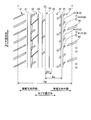
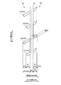
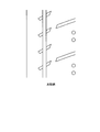
- FIG. 4 is an explanatory view showing a closed drag groove of the pneumatic tire shown in FIG. 3.
- FIG. 3 shows the second land portion 34 and the shoulder land portion 35 in the outer region in the vehicle width direction
- FIG. 4 shows an enlarged view in which the circumferential narrow groove 24 and the plurality of closed drag grooves 41 are extracted. ing.
- the pneumatic tire 10 includes the circumferential narrow groove 24 and a plurality of closed drag grooves 41 (41A, 41B) in an outer region in the vehicle width direction.
- the closed drag groove 41 extends in the tire width direction, penetrates the circumferential narrow groove 24, and does not open to the circumferential main groove 23 and the tire ground contact end T, so that the inside of the second land portion 34 and the shoulder land portion 35 Terminate with For this reason, the closed drag groove 41 branches from the circumferential narrow groove 24 in a branch shape in the tire width direction and terminates in the left and right land portions 34 and 35.
- the end portion of the closed drag groove 41 on the inner side in the tire width direction is simply referred to as “inner end portion”, and the end portion on the outer side in the tire width direction is simply referred to as “outer end portion”.
- a plurality of closed drag grooves 41 (41A, 41B) are arranged at predetermined intervals in the tire circumferential direction.
- a plurality of types of closed drag grooves 41 having different extension lengths are mixedly arranged.
- the extension length L1_min of the shortest closed drag groove 41A and the extension length L1_max of the longest closed drag groove 41B are 1.10 ⁇ L1_max / It is preferable to have a relationship of L1_min ⁇ 3.00, and it is more preferable to have a relationship of 1.20 ⁇ L1_max / L1_min ⁇ 1.60.
- the range of the extension length L1 of the closed drag groove 41 is not particularly limited, but is limited by the range of distances Di and Do (see FIG. 4) of the end portions of the closed drag groove 41 in the land portions 34 and 35 described later. Receive.
- the extension length L1 of the lug groove is a distance in the tire width direction from the inner end portion to the outer end portion of the lug groove when the tire is mounted on the specified rim to apply the specified internal pressure and the unloaded state is applied. Defined. Further, in the configuration including three or more types of closed drag grooves having different extension lengths, the extension length L1_min of the shortest first closed drag groove and the longest second closed drag groove The extension length L1_max of each is measured.
- a plurality of closed drag grooves 41 are arranged at predetermined intervals in the tire circumferential direction. Further, these closed lug grooves 41A and 41B intersect only the circumferential narrow groove 24 and are not connected to other grooves or sipes. Further, the second land portion 34 and the shoulder land portion 35 are not divided in the tire circumferential direction by lug grooves or sipes, and have a tread surface continuous in the tire circumferential direction.
- the first and second closed lug grooves 41A and 41B are arranged in parallel to each other by inclining the longitudinal direction thereof in the same direction and the same inclination angle with respect to the tire circumferential direction. However, the inclination angles ⁇ of the plurality of closed drag grooves 41A and 41B may be different within a range described later.
- the ground contact widths W1 and W2 of the second land portion 34 and the shoulder land portion 35 preferably have a relationship of 1.00 ⁇ W2 / W1 ⁇ 2.00, and 1.20 ⁇ W2 / W1 ⁇ It is more preferable to have a relationship of 1.40.
- the ground contact width W1 of the second land portion 34 has a relationship of 0 ⁇ W1 / TW ⁇ 0.30 with respect to the tire ground contact width TW.
- the contact width of the land portion is the contact between the tire and the flat plate when the tire is mounted on the specified rim to give the specified internal pressure and the load corresponding to the specified load is applied in a stationary state perpendicular to the flat plate. It is measured as the maximum linear distance in the tire axial direction on the surface.
- a plurality of closed drag grooves 41 are arranged with at least one terminal portion offset from each other in the tire width direction.
- the terminal portion of the closed lug groove 41 may be offset on the second land portion 34 side (see FIG. 3), or as described later, the shoulder land portion 35 side, or the second land portion 34 side and the shoulder land portion. It may be offset on both sides of the part 35.
- a plurality of types of closed drag grooves 41A and 41B having different lengths are arranged in a predetermined order in the tire circumferential direction. At this time, two types of closed drag grooves 41A and 41B may be alternately arranged in the tire circumferential direction (see FIG. 3), or three or more types of closed drag grooves 41 may be arranged as described later.
- the ground width W1 (see FIG. 3) preferably has a relationship of 0.10 ⁇ Di / W1 ⁇ 0.80, and more preferably has a relationship of 0.20 ⁇ Di / W1 ⁇ 0.40. .
- the extension length Di in the tire width direction of the closed drag groove 41 in the second land portion 34 is optimized.
- the distance Do (including the minimum value Do_min and the maximum value Do_max in FIG. 4) from the circumferential narrow groove 24 to the outer terminal portion of the closed drag groove 41 (41 ⁇ / b> A, 41 ⁇ / b> B), and the shoulder land portion 35.
- the distance Do (including the minimum value Do_min and the maximum value Do_max in FIG. 4) from the circumferential narrow groove 24 to the outer terminal portion of the closed drag groove 41 (41 ⁇ / b> A, 41 ⁇ / b> B), and the shoulder land portion 35.
- the extension length to the tire width direction of the closed drag groove 41 in the shoulder land part 35 is optimized.
- the distances Di and Do to the end portion of the lug groove are determined from the measurement points of the ground contact widths W1 and W2 of the land portion when the tire is mounted on the specified rim and the specified internal pressure is applied and no load is applied. It is measured as the distance in the tire width direction to the end portion.
- the minimum value Di_min and the maximum value Di_max of the distance Di of the inner end portions of the plurality of closed drag grooves 41 have a relationship of 1.10 ⁇ Di_max / Di_min ⁇ 3.00. It is preferable to have a relationship of 1.20 ⁇ Di_max / Di_min ⁇ 1.60.
- the offset amount ⁇ Di in the tire width direction of the inner terminal portion of the closed drag groove 41 has a relationship of 0.10 ⁇ ⁇ Di / W1 ⁇ 0.60 with respect to the ground contact width W1 (see FIG. 3) of the second land portion 34. And preferably has a relationship of 0.20 ⁇ ⁇ Di / W1 ⁇ 0.40.
- the end portions of the closed drag grooves 41A and 41B are arranged offset in the tire width direction.
- the positions of the inner terminal portions of the closed drag grooves 41A and 41B in the second land portion 34 are optimized, and both wet performance and dry performance of the tire are achieved.
- the wet performance of the tire is efficiently improved by the above configuration.
- the minimum value Do_min and the maximum value Do_max of the distance Do between the outer end portions of the plurality of closed drag grooves 41 have a relationship of 0.90 ⁇ Do_max / Do_min ⁇ 1.10. 0.95 ⁇ Do_max / Do_min ⁇ 1.05 is more preferable.
- the offset amount ⁇ Do in the tire width direction of the outer terminal portion of the closed drag groove 41 has a relationship of 0 ⁇ ⁇ Do / W2 ⁇ 0.10 with respect to the contact width W2 of the shoulder land portion 35 (see FIG. 3). It is preferable to have a relationship of 0 ⁇ ⁇ Do / W2 ⁇ 0.05.
- the end portions of the closed drag grooves 41A and 41B are arranged with their positions aligned in the tire width direction.
- the rigidity of the shoulder land portion 35 can be appropriately secured, so that the dry braking performance of the tire is improved.
- the offset amount ⁇ Di; ⁇ Do of the end portion of the lug groove is calculated as a difference between the distance Di from the circumferential narrow groove to the end portion; the maximum value Di_max of Do; Do_max and the minimum value Di_min; Do_min.
- a plurality of closed drag grooves 41 are arranged with their longitudinal directions inclined in the same direction with respect to the tire circumferential direction.
- the inclination angle ⁇ of the closed drag groove 41 with respect to the tire circumferential direction is preferably in the range of 50 [deg] ⁇ ⁇ ⁇ 80 [deg], and in the range of 55 [deg] ⁇ ⁇ ⁇ 75 [deg]. It is more preferable. Thereby, the drainage property of the closed drag groove 41 is improved, and the pattern noise of the tire caused by the closed drag groove 41 is reduced.
- the inclination angle ⁇ of the lug groove is measured as an angle formed by a straight line connecting both ends of the groove center line of the lug groove and the tire circumferential direction.
- the inclination angle ⁇ 1 of the closed drag groove 41 having the smallest inclination angle ⁇ and the inclination angle ⁇ 2 of the closed drag groove 41 having the largest inclination angle ⁇ satisfy 0 [deg] ⁇ ⁇ 2 ⁇ 1 ⁇ 10 [deg]. It is preferable to have a relationship, and it is more preferable to have a relationship of 0 [deg] ⁇ ⁇ 2 ⁇ 1 ⁇ 5 [deg]. That is, it is preferable that the inclination angle ⁇ of the closed drag groove 41 is substantially constant. Thereby, since the rigidity of a land part can be ensured appropriately, uneven wear is suppressed.
- the groove width Wg of the closed drag groove 41 and the groove width Ws of the circumferential narrow groove 24 preferably have a relationship of 0.30 ⁇ Wg / Ws ⁇ 1.30, and 0.60 ⁇ Wg / Ws ⁇ More preferably, the relationship is 1.00. Thereby, the drainage effect
- the groove width Wg_min of the narrowest closed lug groove 41 and the groove width Wg_max (not shown) of the widest closed lug groove 41 have a relationship of 0.90 ⁇ Wg_max / Wg_min ⁇ 1.10. Preferably, it has a relationship of 0.95 ⁇ Wg_max / Wg_min ⁇ 1.05. That is, it is preferable that the groove width Wg_min of the closed drag groove 41 is uniform. Thereby, since the rigidity of a land part can be ensured appropriately, uneven wear is suppressed.
- the closed drag groove 41 has a straight shape having a constant groove width as a whole, and has a tapered shape in which the groove width is narrowed at the end portion. Further, the left and right end portions of the closed drag groove 41 narrow the groove width in the same direction in the tire circumferential direction, so that the entire closed drag groove 41 has a trapezoidal shape having an upper bottom and a lower bottom in the tire circumferential direction. ing. A plurality of closed lug grooves 41A and 41B are arranged with their directions aligned in the tire circumferential direction.
- the present invention is not limited thereto, and the end portion of the closed drag groove 41 may have a rectangular shape or an arc shape (not shown). Further, the entire closed drag groove 41 may have a rectangular shape or a parallelogram shape (not shown).
- the shoulder land portion 35 in the vehicle width direction outer region includes a plurality of shoulder lug grooves 42 in the vehicle width direction outer region.
- the shoulder lug groove 42 has one end portion in the shoulder land portion 35 and extends in the tire width direction and opens to the tire ground contact end T.
- the shoulder lug groove 42 does not communicate with the circumferential narrow groove 24 and the closed lug groove 41 and does not overlap in the tire width direction.
- a plurality of shoulder lug grooves 42 are arranged at predetermined intervals in the tire circumferential direction.
- the long closed lug groove 41 ⁇ / b> B is on the extension line of the groove center line of the shoulder lug groove 42.
- the groove center line of the shoulder lug groove 42 has a gentle arc shape, and the closed lug groove 41 ⁇ / b> B extends including the extension line of the groove center line of the shoulder lug groove 42.
- the shoulder lug groove 42 extends along the extension line of the closed lug groove 41 ⁇ / b> B, so that the drainage from the second land portion 34 to the shoulder land portion 35 is improved.
- the short closed lug groove 41 ⁇ / b> A may be on an extension line of the groove center line of the shoulder lug groove 42 (not shown).
- the groove center line of the closed lug groove 41 (41A, 41B) is not overlapped with the groove center line of the shoulder lug groove 42 in the tire circumferential direction within the ground contact surface.
- the positional relationship in the tire circumferential direction between the shoulder lug groove 42 and the closed lug groove 41 is set.
- the distances D1A and D1B in the tire circumferential direction between the ends of the groove center lines of the closed lug grooves 41A and 41B and the end of the groove center line of the shoulder lug grooves 42 in FIG. 3 are 0 ⁇ D1A and 0 ⁇ D1B is set.
- the end of the lug groove center line is defined as the intersection of the lug groove opening end on the land tread and the lug groove center line.
- the end portion of the shoulder lug groove 42 and the outer end portion of the closed lug groove 41B facing the shoulder lug groove 42 are separated from each other in the tire width direction. Further, the shoulder lug groove 42 and the closed lug groove 41B are not connected by other grooves or sipes. Further, the distance D2 in the tire width direction from the end portion of the shoulder lug groove 42 to the outer end portion of the closed lug groove 41B and the ground contact width W2 of the shoulder land portion 35 are 0.10 ⁇ D2 / W2 ⁇ 0.60. It is preferable to have the relationship of 0.30 ⁇ D2 / W2 ⁇ 0.50. Thereby, the wet performance and the dry performance of the tire are compatible.
- the lower limit ensures the rigidity of the shoulder land portion 35 and the ground contact area, and ensures the tire dry performance. Moreover, the extension length to the tire width direction of the closed lug groove 41 and the shoulder lug groove 42 is ensured by the said upper limit, and the wet performance of a tire is ensured.
- the shoulder land portion 35 is formed in a groove or sipe in a region between the end portions of all the shoulder lug grooves 42 and the outer end portions of all the closed lug grooves 41 (41 ⁇ / b> A, 41 ⁇ / b> B). It has a plain tread that continues in the tire circumferential direction without being divided. That is, the shoulder lug groove 42 and the closed lug groove 41 do not overlap each other in the tire width direction. Thereby, the dry performance of the tire is further improved.
- the arrangement interval P1 of the closed lug grooves 41 and the arrangement interval P2 of the shoulder lug grooves 42 in the tire circumferential direction have a relationship of 0.30 ⁇ P1 / P2 ⁇ 0.70. It is more preferable to have a relationship of 40 ⁇ P1 / P2 ⁇ 0.60. Thereby, arrangement
- a pair of closed lug grooves 41 ⁇ / b> A and 41 ⁇ / b> B and a single shoulder lug groove 42, each having a short length and a long length, are arranged in the tire circumferential direction with the same pitch length.
- the lug groove arrangement intervals P1 and P2 are measured using the intersection between the groove center line of the lug groove and the groove center line of the circumferential narrow groove or the tire ground contact end as a measurement point.
- the outer terminal portions of the closed drag grooves 41 (41A, 41B) in the shoulder land portion 35 are arranged with their positions aligned in the tire width direction. For this reason, the offset amount ⁇ Do in the tire width direction of the outer end portion of the closed lug groove 41 is zero.
- the outer terminal portions of the closed drag grooves 41 (41A, 41B) in the shoulder land portion 35 are arranged slightly offset from each other in the tire width direction. Specifically, the offset amount ⁇ Do of the outer end portion of the closed drag groove 41 is set so as not to become zero within a predetermined range with respect to the ground contact width W2 of the shoulder land portion 35. Even with this configuration, the rigidity of the shoulder land portion 35 can be appropriately secured.
- the end portions of the closed drag grooves 41 are arranged in the second land portion 34 so as to be aligned in the tire width direction. They are arranged in the land portion 35 while being offset in the tire width direction.
- the offset amount ⁇ Di of the inner terminal portion of the closed drag groove 41 has a relationship of 0 ⁇ ⁇ Di / W1 ⁇ 0.05 with respect to the ground contact width W1 of the second land portion 34, and the closed drag
- the offset amount ⁇ Do at the outer end portion of the groove 41 preferably has a relationship of 0.10 ⁇ ⁇ Do / W2 ⁇ 0.60 with respect to the ground contact width W2 of the shoulder land portion 35.
- the closed drag grooves 41 are arranged with the center positions in the tire width direction aligned.
- the distance (not shown) between the center point of the closed lug groove 41 in the tire width direction and the groove center line of the circumferential narrow groove 24 is 50% relative to the groove width Ws of the circumferential narrow groove 24. It is preferable to be in the following range. That is, it is preferable that the center point of the closed lug groove 41 in the tire width direction is inside the circumferential narrow groove 24.
- the two types of closed drag grooves 41A and 41B having different lengths are alternately arranged in the tire circumferential direction.
- the total number of closed lug grooves 41 (41A, 41B) is twice the total number of shoulder lug grooves 42, and the total number of long closed lug grooves 41B is set to be the same as the total number of shoulder lug grooves 42. (See FIG. 3).
- the present invention is not limited to this, and as shown in FIG. 8, three types of closed drag grooves 41A to 41C having different lengths may be arranged in a predetermined arrangement order in the tire circumferential direction.
- the closed drag grooves 41A to 41C are repeatedly arranged in the order of short, medium, and long from the bottom to the top of the figure.
- the relationship between the extended length L1_min of the shortest closed drag groove 41A and the extended length L1_max of the longest closed drag groove 41B is 1.10 ⁇ L1_max / L1_min ⁇ 3.00. Is set to have.
- the total number of closed lug grooves 41 (41A to 41C) is three times the total number of shoulder lug grooves 42, and the total number of long closed lug grooves 41B is set equal to the total number of shoulder lug grooves 42. It is preferable.
- the shoulder lug groove 42 can be arrange
- the medium-sized closed drag groove 41 ⁇ / b> C in FIG. 8 has the same extension length as the short closed drag groove 41 ⁇ / b> A, so that a short and pair of the same extension length is provided.
- the closed drag grooves 41A may be arranged between adjacent long closed drag grooves 41B and 41B.
- the pneumatic tire 10 includes the circumferential main groove 23 and the circumferential main groove arranged in one region (the vehicle width direction outer region in FIG. 2) having the tire equator plane CL as a boundary. 23, a circumferential narrow groove 24 disposed on the outer side in the tire width direction, and a shoulder land portion 35 and a second land portion 34 partitioned by the circumferential main groove 23 and the circumferential narrow groove 24 (see FIG. 2).
- the pneumatic tire 10 extends in the tire width direction and penetrates the circumferential narrow groove 24, and has an inner end portion in the second land portion 34 in the tire width direction and an outer end portion in the shoulder land portion 35.
- a plurality of closed drag grooves 41 (41A, 41B) are provided (see FIG. 3).
- extension length L1_min in the tire width direction of the shortest first closed lug groove 41A and the extension length L1_max in the tire width direction of the longest second closed lug groove 41B are 1. 10 ⁇ L1_max / L1_min ⁇ 3.00.
- the closed drag groove 41 penetrates the circumferential narrow groove 24, thereby improving drainage near the circumferential narrow groove 24 and improving the wet performance of the tire.
- the closed lug groove 41 does not open to the circumferential main groove 23 and the tire ground contact end T, the rigidity of the left and right land portions 34 and 35 partitioned by the circumferential narrow groove 24 is ensured.
- a plurality of types of closed drag grooves 41 (41A, 41B) having different extension lengths are arranged at predetermined intervals in the tire circumferential direction, and therefore, at least one land portion (see FIG.
- the end portions of the closed drag grooves 41A, 41B in the second land portion 34) are arranged in the tire circumferential direction while being offset from each other in the tire width direction. For this reason, compared with the structure (illustration omitted) where the right-and-left terminal part of a closed lug groove is arranged with the position of a tire width direction aligned, it is a long lug groove part (in FIG. 3, 2nd closed lug groove 41B). Is located on the tread of one land portion (in FIG. 3, the second land portion 34), and at the same time, a wide grounding area is formed between adjacent long lug grooves. . Thereby, there exists an advantage which the wet performance and dry performance of a tire improve efficiently.
- the minimum value Di_min and the maximum value Di_max (see FIG. 4) of the distance Di from the circumferential narrow groove 24 to the inner terminal portion of the closed drag groove 41 (41A, 41B) are 1.10.
- the offset amount ⁇ Di in the tire width direction of the inner terminal portion of the closed drag groove 41 (41A, 41B) is 0 with respect to the ground contact width W1 (see FIG. 3) of the second land portion 34. 20 ⁇ ⁇ Di / W1 ⁇ 0.40.
- the minimum value Do_min and the maximum value Do_max of the distance Do from the circumferential narrow groove 24 to the outer terminal portion of the closed drag groove 41 (41A, 41B) are 0.90 ⁇ Do_max / Do_min ⁇ . It has a relationship of 1.10. Thereby, there is an advantage that the rigidity of the shoulder land portion 35 is ensured and the dry braking performance of the tire is improved.
- the distance Di (including the minimum value Di_min and the maximum value Di_max of the distance Di in FIG. 4) from the circumferential narrow groove 24 to the inner terminal portion of the closed drag groove 41, and the second land portion. 34 has a relationship of 0.20 ⁇ Di / W1 ⁇ 0.40 with the grounding width W1 (see FIG. 3).
- the distance Do (including the minimum value Do_min and the maximum value Do_max of the distance Do in FIG. 4) from the circumferential narrow groove 24 to the outer end portion of the closed drag groove 41, and the shoulder land portion.
- the ground contact width W2 of 35 (see FIG. 3) has a relationship of 0.20 ⁇ Do / W2 ⁇ 0.40.
- the inclination angle ⁇ of the closed drag groove 41 with respect to the tire circumferential direction is in the range of 55 [deg] ⁇ ⁇ ⁇ 75 [deg] (see FIG. 4).
- the groove width Wg of the closed drag groove 41 and the groove width Ws of the circumferential narrow groove 24 have a relationship of 0.60 ⁇ Wg / Ws ⁇ 1.00.
- the groove width Wg_min of the narrowest closed lug groove 41 and the groove width Wg_max (not shown) of the widest closed lug groove 41 are 0.90 ⁇ Wg_max / Wg_min ⁇ 1.
- a pair of closed drag grooves 41A and 41B having different lengths are alternately arranged in the tire circumferential direction (see FIG. 2). Accordingly, there is an advantage that the wet performance and the dry performance of the tire are efficiently compatible.
- the shoulder land portion 35 has one end portion in the shoulder land portion 35 and includes a shoulder lug groove 42 that extends in the tire width direction and opens to the tire ground contact end T ( (See FIG. 2).
- the closed lug groove 41 (the long closed lug groove 41 ⁇ / b> B in FIG. 2) is on an extension of the groove center line of the shoulder lug groove 42.
- the shoulder land portion 35 has one end portion in the shoulder land portion 35 and includes a shoulder lug groove 42 that extends in the tire width direction and opens to the tire ground contact end T ( (See FIG. 2). Further, the groove center line of the closed lug groove 41 does not overlap the groove center line of the shoulder lug groove 42 in the tire circumferential direction. Thereby, the pattern noise resulting from the overlap of a lug groove is reduced, and there exists an advantage which the quietness of a tire improves.
- the distance D2 in the tire width direction from the end portion of the shoulder lug groove 42 to the outer end portion of the closed lug groove 41 facing the shoulder lug groove 42, and the contact width W2 of the shoulder land portion 35. Have a relationship of 0.30 ⁇ D2 / W2 ⁇ 0.50 (see FIG. 3).
- the arrangement interval P1 of the closed lug grooves 41 and the arrangement interval P2 of the shoulder lug grooves 42 in the tire circumferential direction have a relationship of 0.30 ⁇ P1 / P2 ⁇ 0.70.
- the pneumatic tire 10 is provided with a mounting direction display unit (not shown) for designating that one of the regions (the vehicle width direction outer region in FIG. 2) should be mounted on the vehicle with the vehicle width direction outer side.
- FIG. 10 is a chart showing the results of the performance test of the pneumatic tire according to the embodiment of the present invention.
- FIG. 11 is an explanatory view showing a test tire of the conventional example shown in FIG.
- FIG. 12 is an explanatory view showing a test tire of the comparative example shown in FIG.
- test tire having a tire size of 245 / 40R18 97Y is assembled to a rim having a rim size of 18 ⁇ 8.5 J, and an internal pressure of 230 [kPa] and a specified load of JATMA are applied to the test tire.
- a test tire is mounted on all wheels of a passenger car that is a test vehicle.
- test vehicle runs on a dry road test course having a flat circuit around 60 [km / h] to 100 [km / h]. Then, the test driver performs sensory evaluation on the steering performance at the time of race change and cornering and the stability at the time of straight traveling. This evaluation is performed by index evaluation using the conventional example as a reference (100), and the larger the value, the better.
- test vehicle runs on the test course with a rough road surface at 10 [km / h] to 20 [km / h], and the test driver performs sensory evaluation on the in-vehicle noise.
- This evaluation is performed by index evaluation using the conventional example as a reference (100), and the larger the value, the better.
- the test tires of Examples 1 to 11 have the configurations shown in FIGS. 1 to 3, the circumferential main groove 23 and the circumferential narrow groove 24, and two types of long and short closed lug grooves 41A and 41B.
- a shoulder lug groove 42 is provided in the outer region in the vehicle width direction.
- the tread width TW is 200 [mm]
- the distance Dm between the circumferential main grooves 23 is 25.0 [mm]
- the distance Dn between the circumferential narrow grooves 24 is 60.0 [mm].
- the groove width Wm of the circumferential main groove 23 is 15.0 [mm]
- the groove width Ws of the circumferential narrow groove 24 is 5.0 [mm]
- the width of the second land portion 34 is provided in the outer region in the vehicle width direction.
- the tread width TW is 200 [mm]
- the distance Dm between the circumferential main grooves 23 is 25.0 [mm]
- the distance Dn between the circumferential narrow grooves 24 is 60.0 [mm].
- W1 is 27.0 [mm]
- the width W2 of the shoulder land portion 35 is 36.0 [mm].
- a pair of short and long closed lug grooves 41A and 41B and one shoulder lug groove 42 are arranged per unit pitch.
- the conventional test tire does not include the long closed drag groove 41B in the test tire of Example 1. Further, the short closed lug groove is located away from the extension line of the groove center line of the shoulder lug groove. As shown in FIG. 12, in the test tire of the comparative example, the extension lengths of the closed drag grooves 41A and 41B in the test tire of Example 1 are set to be constant.
Landscapes
- Engineering & Computer Science (AREA)
- Mechanical Engineering (AREA)
- Tires In General (AREA)
Abstract
この空気入りタイヤは、タイヤ赤道面を境界とする車幅方向外側領域に配置された周方向主溝23と、周方向主溝23のタイヤ幅方向外側に配置された周方向細溝24と、周方向主溝23および周方向細溝24に区画されたショルダー陸部35およびセカンド陸部34とを備える。また、空気入りタイヤは、タイヤ幅方向に延在して周方向細溝24を貫通し、タイヤ幅方向における内側終端部をセカンド陸部34内に有すると共に外側終端部をショルダー陸部35内に有する複数のクローズドラグ溝41A、41Bを備える。また、最も短尺な第一のクローズドラグ溝41Aのタイヤ幅方向の延在長さL1_minと、最も長尺な第二のクローズドラグ溝41Bのタイヤ幅方向の延在長さL1_maxとが、1.10≦L1_max/L1_min≦3.00の関係を有する。
Description
この発明は、空気入りタイヤに関し、さらに詳しくは、タイヤのドライ性能およびウェット性能を両立できる空気入りタイヤに関する。
近年の空気入りタイヤでは、サーキット走行だけではなく、市街地およびハイウェイの走行時にもスポーツ性能を向上すべき要請がある。このため、タイヤのドライ性能およびウェット性能を両立するために、タイヤ赤道面を境界とする車幅方向内側領域に2本の周方向主溝を備えると共に車幅方向外側領域に単一の周方向主溝と単一の周方向細溝とを備える構成が採用されている。かかる構成を採用する従来の空気入りタイヤとして、特許文献1に記載される技術が知られている。
この発明は、タイヤのドライ性能およびウェット性能を両立できる空気入りタイヤを提供することを目的とする。
上記目的を達成するため、この発明にかかる空気入りタイヤは、タイヤ赤道面を境界とする一方の領域に配置された周方向主溝と、前記周方向主溝のタイヤ幅方向外側に配置された周方向細溝と、前記周方向主溝および前記周方向細溝に区画されたショルダー陸部およびセカンド陸部とを備える空気入りタイヤであって、タイヤ幅方向に延在して前記周方向細溝を貫通し、タイヤ幅方向における内側終端部を前記セカンド陸部内に有すると共に外側終端部を前記ショルダー陸部内に有する複数のクローズドラグ溝を備え、且つ、最も短尺な第一の前記クローズドラグ溝のタイヤ幅方向の延在長さL1_minと最も長尺な第二の前記クローズドラグ溝のタイヤ幅方向の延在長さL1_maxとが、1.10≦L1_max/L1_min≦3.00の関係を有することを特徴とする。
この発明にかかる空気入りタイヤでは、(1)クローズドラグ溝が周方向細溝を貫通することにより、周方向細溝付近の排水性が向上して、タイヤのウェット性能が向上する。同時に、クローズドラグ溝が周方向主溝およびタイヤ接地端に開口しないので、周方向細溝に区画された左右の陸部の剛性が確保される。これらにより、タイヤのウェット性能およびドライ性能が効率的に両立する利点がある。また、(2)相互に異なる延在長さをもつ複数種類のクローズドラグ溝がタイヤ周方向に所定間隔で配列されるので、必然的に、少なくとも一方の陸部におけるクローズドラグ溝の終端部が、タイヤ幅方向に相互にオフセットしつつタイヤ周方向に配列される。このため、クローズドラグ溝の左右の終端部がタイヤ幅方向の位置を揃えて配列される構成と比較して、長尺なラグ溝部が1つの陸部の踏面に配置され、同時に、幅広な接地領域が隣り合う長尺なラグ溝部の間に形成される。これにより、タイヤのウェット性能およびドライ性能が効率的に向上する利点がある。
以下、この発明につき図面を参照しつつ詳細に説明する。なお、この実施の形態によりこの発明が限定されるものではない。また、この実施の形態の構成要素には、発明の同一性を維持しつつ置換可能かつ置換自明なものが含まれる。また、この実施の形態に記載された複数の変形例は、当業者自明の範囲内にて任意に組み合わせが可能である。
[空気入りタイヤ]
図1は、この発明の実施の形態にかかる空気入りタイヤを示すタイヤ子午線方向の断面図である。同図は、タイヤ径方向の片側領域の断面図を示している。また、同図は、空気入りタイヤの一例として、乗用車用ラジアルタイヤを示している。
図1は、この発明の実施の形態にかかる空気入りタイヤを示すタイヤ子午線方向の断面図である。同図は、タイヤ径方向の片側領域の断面図を示している。また、同図は、空気入りタイヤの一例として、乗用車用ラジアルタイヤを示している。
同図において、タイヤ子午線方向の断面とは、タイヤ回転軸(図示省略)を含む平面でタイヤを切断したときの断面をいう。また、符号CLは、タイヤ赤道面であり、タイヤ回転軸方向にかかるタイヤの中心点を通りタイヤ回転軸に垂直な平面をいう。また、タイヤ幅方向とは、タイヤ回転軸に平行な方向をいい、タイヤ径方向とは、タイヤ回転軸に垂直な方向をいう。
また、車幅方向内側および車幅方向外側が、タイヤを車両に装着したときの車幅方向に対する向きとして定義される。また、タイヤ赤道面を境界とする左右の領域が、車幅方向外側領域および車幅方向内側領域としてそれぞれ定義される。また、空気入りタイヤが、車両に対するタイヤ装着方向を示す装着方向表示部(図示省略)を備える。装着方向表示部は、例えば、タイヤのサイドウォール部に付されたマークや凹凸によって構成される。例えば、ECER30(欧州経済委員会規則第30条)が、車両装着状態にて車幅方向外側となるサイドウォール部に車両装着方向の表示部を設けることを義務付けている。
空気入りタイヤ10は、タイヤ回転軸を中心とする環状構造を有し、一対のビードコア11、11と、一対のビードフィラー12、12と、カーカス層13と、ベルト層14と、トレッドゴム15と、一対のサイドウォールゴム16、16と、一対のリムクッションゴム17、17とを備える(図1参照)。
一対のビードコア11、11は、スチールから成る1本あるいは複数本のビードワイヤを環状かつ多重に巻き廻して成り、ビード部に埋設されて左右のビード部のコアを構成する。一対のビードフィラー12、12は、一対のビードコア11、11のタイヤ径方向外周にそれぞれ配置されてビード部を補強する。
カーカス層13は、1枚のカーカスプライから成る単層構造あるいは複数枚のカーカスプライを積層して成る多層構造を有し、左右のビードコア11、11間にトロイダル状に架け渡されてタイヤの骨格を構成する。また、カーカス層13の両端部は、ビードコア11およびビードフィラー12を包み込むようにタイヤ幅方向外側に巻き返されて係止される。また、カーカス層13のカーカスプライは、スチールあるいは有機繊維材(例えば、アラミド、ナイロン、ポリエステル、レーヨンなど)から成る複数のカーカスコードをコートゴムで被覆して圧延加工して構成され、絶対値で80[deg]以上90[deg]以下のカーカス角度(タイヤ周方向に対するカーカスコードの長手方向の傾斜角として定義される)を有する。
ベルト層14は、一対の交差ベルト141、142と、ベルトカバー143とを積層して成り、カーカス層13の外周に掛け廻されて配置される。一対の交差ベルト141、142は、スチールあるいは有機繊維材から成る複数のベルトコードをコートゴムで被覆して圧延加工して構成され、絶対値で20[deg]以上55[deg]以下のベルト角度を有する。また、一対の交差ベルト141、142は、相互に異符号のベルト角度(タイヤ周方向に対するベルトコードの長手方向の傾斜角として定義される)を有し、ベルトコードの長手方向を相互に交差させて積層される(いわゆるクロスプライ構造)。ベルトカバー143は、スチールあるいは有機繊維材から成るベルトカバーコードをコートゴムで被覆して構成され、絶対値で0[deg]以上10[deg]以下のベルト角度を有する。また、ベルトカバー143は、例えば、1本あるいは複数本のベルトカバーコードをコートゴムで被覆して成るストリップ材であり、このストリップ材を交差ベルト141、142の外周面に対してタイヤ周方向に複数回かつ螺旋状に巻き付けて構成され得る。
トレッドゴム15は、カーカス層13およびベルト層14のタイヤ径方向外周に配置されてタイヤのトレッド部を構成する。一対のサイドウォールゴム16、16は、カーカス層13のタイヤ幅方向外側にそれぞれ配置されて左右のサイドウォール部を構成する。一対のリムクッションゴム17、17は、左右のビードコア11、11およびカーカス層13の巻き返し部のタイヤ径方向内側にそれぞれ配置されて、ビード部のリム嵌合面を構成する。
[トレッドパターン]
図2は、図1に記載した空気入りタイヤのトレッド面を示す平面図である。同図は、オールシーズン用タイヤのトレッドパターンを示している。同図において、タイヤ周方向とは、タイヤ回転軸周りの方向をいう。また、符号Tは、タイヤ接地端であり、寸法記号TWは、タイヤ接地幅である。
図2は、図1に記載した空気入りタイヤのトレッド面を示す平面図である。同図は、オールシーズン用タイヤのトレッドパターンを示している。同図において、タイヤ周方向とは、タイヤ回転軸周りの方向をいう。また、符号Tは、タイヤ接地端であり、寸法記号TWは、タイヤ接地幅である。
図2に示すように、空気入りタイヤ10は、タイヤ周方向に延在する複数の周方向主溝21~23および周方向細溝24と、これらの周方向溝21~24に区画された複数の陸部31~35とをトレッド面に備える。
主溝とは、JATMAに規定されるウェアインジケータの表示義務を有する溝であり、一般に3.0[mm]以上の溝幅および6.0[mm]以上の溝深さを有する。また、後述するラグ溝とは、タイヤ幅方向に延在する横溝であり、タイヤ接地時に開口して溝として機能する。また、後述するサイプとは、トレッド踏面に形成された切り込みであり、タイヤ接地時に閉塞する点でラグ溝と区別される。
なお、周方向細溝24については、後述する。
溝幅は、タイヤを規定リムに装着して規定内圧を充填した無負荷状態にて、溝開口部における左右の溝壁の距離の最大値として測定される。陸部が切欠部や面取部をエッジ部に有する構成では、溝長さ方向を法線方向とする断面視にて、トレッド踏面と溝壁の延長線との交点を測定点として、溝幅が測定される。また、溝がタイヤ周方向にジグザグ状あるいは波状に延在する構成では、溝壁の振幅の中心線を測定点として、溝幅が測定される。
溝深さは、タイヤを規定リムに装着して規定内圧を充填した無負荷状態にて、トレッド踏面から溝底までの距離の最大値として測定される。また、溝が部分的な凹凸部やサイプを溝底に有する構成では、これらを除外して溝深さが測定される。
規定リムとは、JATMAに規定される「標準リム」、TRAに規定される「Design Rim」、あるいはETRTOに規定される「Measuring Rim」をいう。また、規定内圧とは、JATMAに規定される「最高空気圧」、TRAに規定される「TIRE LOAD LIMITS AT VARIOUS COLD INFLATION PRESSURES」の最大値、あるいはETRTOに規定される「INFLATION PRESSURES」をいう。また、規定荷重とは、JATMAに規定される「最大負荷能力」、TRAに規定される「TIRE LOAD LIMITS AT VARIOUS COLD INFLATION PRESSURES」の最大値、あるいはETRTOに規定される「LOAD CAPACITY」をいう。ただし、JATMAにおいて、乗用車用タイヤの場合には、規定内圧が空気圧180[kPa]であり、規定荷重が最大負荷能力の88[%]である。
例えば、図2の構成では、空気入りタイヤ10が、タイヤ赤道面CLを中心とする左右非対称なトレッドパターンを有している。また、タイヤ赤道面CLを境界とする車幅方向内側領域が2本の周方向主溝21、22を有し、車幅方向外側領域が1本の周方向主溝23と1本の周方向細溝24とを備えている。また、これらの周方向溝21、22;23、24が、タイヤ赤道面CLを中心として、左右対称に配置されている。また、これらの周方向溝21~24により、5列の陸部31~35が区画されている。また、1つの陸部33が、タイヤ赤道面CL上に配置されている。
また、車幅方向内側領域の最外周方向主溝21あるいは車幅方向外側領域の周方向細溝24に区画されたタイヤ幅方向外側の陸部31、35をショルダー陸部として定義する。ショルダー陸部31、35は、タイヤ幅方向の最も外側の陸部であり、タイヤ接地端T上に位置する。また、最外周方向主溝21あるいは周方向細溝24に区画されたタイヤ幅方向内側の陸部32、34をセカンド陸部として定義する。したがって、セカンド陸部32、34は、最外周方向主溝21、24を挟んでショルダー陸部31、35に隣り合う。また、セカンド陸部32、34よりもタイヤ赤道面CL側にある陸部33をセンター陸部として定義する。
[車幅方向外側領域]
図2の構成では、タイヤ赤道面CLを境界とする車幅方向外側領域が、単一の周方向主溝23と、この周方向主溝23よりもタイヤ幅方向外側に配置された単一の周方向細溝24とを備える。また、これらの周方向溝23、24により、ショルダー陸部35およびセカンド陸部34が区画される。
図2の構成では、タイヤ赤道面CLを境界とする車幅方向外側領域が、単一の周方向主溝23と、この周方向主溝23よりもタイヤ幅方向外側に配置された単一の周方向細溝24とを備える。また、これらの周方向溝23、24により、ショルダー陸部35およびセカンド陸部34が区画される。
例えば、図2の構成では、周方向主溝23および周方向細溝24が、一定の溝幅をもつストレート形状を有する。また、タイヤ赤道面CLから周方向主溝23の溝中心線までの距離Dmが、タイヤ接地幅TWに対して8[%]以上12[%]以下の範囲にある。また、タイヤ赤道面CLから周方向細溝24の溝中心線までの距離Dnが、タイヤ接地幅TWに対して26[%]以上32[%]以下の範囲にある。
周方向主溝の溝中心線は、周方向主溝の溝幅の左右の測定点の中点を通りタイヤ周方向に平行な直線として定義される。
タイヤ接地幅TWは、タイヤを規定リムに装着して規定内圧を付与すると共に静止状態にて平板に対して垂直に置いて規定荷重に対応する負荷を付与したときのタイヤと平板との接触面におけるタイヤ軸方向の最大直線距離として測定される。
タイヤ接地端Tは、タイヤを規定リムに装着して規定内圧を付与すると共に静止状態にて平板に対して垂直に置いて規定荷重に対応する負荷を加えたときのタイヤと平板との接触面におけるタイヤ軸方向の最大幅位置として定義される。
また、周方向主溝23の溝幅が5.0[mm]以上25.0[mm]以下の範囲にあり、溝深さが5.0[mm]以上12.0[mm]以下の範囲にある(図中の寸法記号省略)。また、周方向細溝24の溝幅Ws(後述する図4参照)が3.0[mm]以上7.0[mm]以下の範囲にあり、溝深さが3.0[mm]以上7.0[mm]以下の範囲にある(図中の寸法記号省略)。
また、図2の構成では、車幅方向外側領域の周方向主溝23に区画された左右の陸部33、34の周方向主溝23側のエッジ部が、サイプおよび溝の開口部をもたないプレーン構造を有することにより、タイヤ周方向に連続して延在している。これにより、タイヤの騒音性能が高められている。
[車幅方向外側領域のクローズドラグ溝]
図3は、図2に記載した空気入りタイヤの車幅方向外側領域の要部を示す拡大図である。図4は、図3に記載した空気入りタイヤのクローズドラグ溝を示す説明図である。これらの図において、図3は、車幅方向外側領域のセカンド陸部34およびショルダー陸部35を示し、図4は、周方向細溝24および複数のクローズドラグ溝41を抽出した拡大図を示している。
図3は、図2に記載した空気入りタイヤの車幅方向外側領域の要部を示す拡大図である。図4は、図3に記載した空気入りタイヤのクローズドラグ溝を示す説明図である。これらの図において、図3は、車幅方向外側領域のセカンド陸部34およびショルダー陸部35を示し、図4は、周方向細溝24および複数のクローズドラグ溝41を抽出した拡大図を示している。
図2に示すように、空気入りタイヤ10は、上記した周方向細溝24と、複数のクローズドラグ溝41(41A、41B)とを車幅方向外側領域に備える。
クローズドラグ溝41は、タイヤ幅方向に延在して周方向細溝24を貫通し、周方向主溝23およびタイヤ接地端Tに開口することなく、セカンド陸部34およびショルダー陸部35の内部で終端する。このため、クローズドラグ溝41が、周方向細溝24からタイヤ幅方向に枝状に分岐して左右の陸部34、35の内部で終端する。ここでは、クローズドラグ溝41のタイヤ幅方向内側の終端部を単に「内側終端部」と呼び、タイヤ幅方向外側の終端部を単に「外側終端部」と呼ぶ。また、複数のクローズドラグ溝41(41A、41B)が、タイヤ周方向に所定間隔で配列される。
上記の構成では、クローズドラグ溝41が周方向細溝24を貫通することにより、周方向細溝24付近の排水性が向上して、タイヤのウェット性能が向上する。同時に、クローズドラグ溝41が周方向主溝23およびタイヤ接地端Tに開口しないので、周方向細溝24に区画された左右の陸部34、35の剛性が確保される。これらにより、タイヤのウェット性能およびドライ性能が効率的に両立する。
また、図3に示すように、相互に異なる延在長さをもつ複数種類のクローズドラグ溝41(41A、41B)が、混在して配置される。また、複数種類のクローズドラグ溝41のうち、最も短尺なクローズドラグ溝41Aの延在長さL1_minと、最も長尺なクローズドラグ溝41Bの延在長さL1_maxとが、1.10≦L1_max/L1_min≦3.00の関係を有することが好ましく、1.20≦L1_max/L1_min≦1.60の関係を有することがより好ましい。クローズドラグ溝41の延在長さL1の範囲は、特に限定がないが、後述する各陸部34、35におけるクローズドラグ溝41の終端部の距離Di、Do(図4参照)の範囲により制約を受ける。
ラグ溝の延在長さL1は、タイヤを規定リムに装着して規定内圧を付与すると共に無負荷状態としたときの、ラグ溝の内側終端部から外側終端部までのタイヤ幅方向の距離として定義される。また、相互に異なる延在長さをもつ3種類以上のクローズドラグ溝を備える構成では、最も短尺な第一のクローズドラグ溝の延在長さL1_minと、最も長尺な第二のクローズドラグ溝の延在長さL1_maxとが、それぞれ測定される。
例えば、図3の構成では、複数のクローズドラグ溝41(41A、41B)が、タイヤ周方向に所定間隔で配列されている。また、これらのクローズドラグ溝41A、41Bが、周方向細溝24のみに交差し、他の溝あるいはサイプに接続していない。また、セカンド陸部34およびショルダー陸部35が、ラグ溝あるいはサイプによりタイヤ周方向に分断されておらず、タイヤ周方向に連続した踏面を有している。また、第一および第二のクローズドラグ溝41A、41Bが、その長手方向をタイヤ周方向に対して同一方向かつ同一傾斜角で傾斜させることにより、相互に平行に配列されている。しかし、複数のクローズドラグ溝41A、41Bの傾斜角θが後述する範囲内で相異しても良い。
また、図3において、セカンド陸部34およびショルダー陸部35の接地幅W1、W2が、1.00≦W2/W1≦2.00の関係を有することが好ましく、1.20≦W2/W1≦1.40の関係を有することがより好ましい。また、セカンド陸部34の接地幅W1が、タイヤ接地幅TWに対して0≦W1/TW≦0.30の関係を有することが好ましい。これにより、周方向主溝23および周方向細溝24に区画された左右の陸部34、35の接地幅W1、W2が適正化される。
陸部の接地幅は、タイヤを規定リムに装着して規定内圧を付与すると共に静止状態にて平板に対して垂直に置いて規定荷重に対応する負荷を付与したときのタイヤと平板との接触面におけるタイヤ軸方向の最大直線距離として測定される。
また、複数のクローズドラグ溝41(41A、41B)が、少なくとも一方の終端部をタイヤ幅方向に相互にオフセットして配列される。このとき、クローズドラグ溝41の終端部が、セカンド陸部34側でオフセットしても良いし(図3参照)、後述するようにショルダー陸部35側、あるいは、セカンド陸部34側およびショルダー陸部35側の双方でオフセットしても良い。また、相互に異なる長さをもつ複数種類のクローズドラグ溝41A、41Bが、タイヤ周方向に所定の順序で配列される。このとき、2種類のクローズドラグ溝41A、41Bがタイヤ周方向に交互に配列されても良いし(図3参照)、後述のように3種類以上のクローズドラグ溝41が配列されても良い。
また、図4において、周方向細溝24からクローズドラグ溝41(41A、41B)の内側終端部までの距離Di(図4における最小値Di_minおよび最大値Di_maxを含む。)と、セカンド陸部34の接地幅W1(図3参照)とが、0.10≦Di/W1≦0.80の関係を有することが好ましく、0.20≦Di/W1≦0.40の関係を有することがより好ましい。これにより、セカンド陸部34におけるクローズドラグ溝41のタイヤ幅方向への延在長さDiが適正化される。
また、図4において、周方向細溝24からクローズドラグ溝41(41A、41B)の外側終端部までの距離Do(図4における最小値Do_minおよび最大値Do_maxを含む。)と、ショルダー陸部35の接地幅W2(図3参照)とが、0.10≦Do/W2≦0.60の関係を有することが好ましく、0.20≦Do/W2≦0.40の関係を有することがより好ましい。これにより、ショルダー陸部35におけるクローズドラグ溝41のタイヤ幅方向への延在長さが適正化される。
ラグ溝の終端部までの距離Di、Doは、タイヤを規定リムに装着して規定内圧を付与すると共に無負荷状態としたときの、陸部の接地幅W1、W2の測定点からラグ溝の終端部までのタイヤ幅方向の距離として測定される。また、相互に異なる数値をもつ3種類以上の距離Di、Doが存在する構成では、距離Di;Doの最大値Di_max;Do_maxおよび最小値Di_min;Do_minが上記条件をそれぞれ満たすことを要する。
また、図4において、複数のクローズドラグ溝41(41A、41B)の内側終端部の距離Diの最小値Di_minと最大値Di_maxとが、1.10≦Di_max/Di_min≦3.00の関係を有することが好ましく、1.20≦Di_max/Di_min≦1.60の関係を有することがより好ましい。また、クローズドラグ溝41の内側終端部のタイヤ幅方向のオフセット量ΔDiが、セカンド陸部34の接地幅W1(図3参照)に対して、0.10≦ΔDi/W1≦0.60の関係を有することが好ましく、0.20≦ΔDi/W1≦0.40の関係を有することがより好ましい。したがって、セカンド陸部34では、クローズドラグ溝41A、41Bの終端部がタイヤ幅方向にオフセットして配列される。これにより、セカンド陸部34におけるクローズドラグ溝41A、41Bの内側終端部の位置が適正化されて、タイヤのウェット性能およびドライ性能が両立する。特に、セカンド陸部34は、ウェット性能に対する寄与が大きいため、上記の構成により、タイヤのウェット性能が効率的に向上する。
一方で、複数のクローズドラグ溝41(41A、41B)の外側終端部の距離Doの最小値Do_minと最大値Do_maxとが、0.90≦Do_max/Do_min≦1.10の関係を有することが好ましく、0.95≦Do_max/Do_min≦1.05の関係を有することがより好ましい。また、クローズドラグ溝41の外側終端部のタイヤ幅方向のオフセット量ΔDoが、ショルダー陸部35の接地幅W2(図3参照)に対して、0≦ΔDo/W2≦0.10の関係を有することが好ましく、0≦ΔDo/W2≦0.05の関係を有することがより好ましい。したがって、ショルダー陸部35では、クローズドラグ溝41A、41Bの終端部がタイヤ幅方向に位置を揃えて配列される。これにより、ショルダー陸部35の剛性を適正に確保できるので、タイヤのドライ制動性能が向上する。
ラグ溝の終端部のオフセット量ΔDi;ΔDoは、周方向細溝から終端部までの距離Di;Doの最大値Di_max;Do_maxおよび最小値Di_min;Do_minの差として算出される。
また、図4に示すように、複数のクローズドラグ溝41(41A、41B)が、その長手方向をタイヤ周方向に対して同一方向に傾斜させて配置される。また、クローズドラグ溝41のタイヤ周方向に対する傾斜角θが、50[deg]≦θ≦80[deg]の範囲にあることが好ましく、55[deg]≦θ≦75[deg]の範囲にあることがより好ましい。これにより、クローズドラグ溝41の排水性が向上し、また、クローズドラグ溝41に起因するタイヤのパターンノイズが低減される。
ラグ溝の傾斜角θは、ラグ溝の溝中心線の両端部を結ぶ直線とタイヤ周方向とのなす角として測定される。
また、最も小さい傾斜角θをもつクローズドラグ溝41の傾斜角θ1と最も大きい傾斜角θをもつクローズドラグ溝41の傾斜角θ2とが、0[deg]≦θ2-θ1≦10[deg]の関係を有することが好ましく、0[deg]≦θ2-θ1≦5[deg]の関係を有することがより好ましい。すなわち、クローズドラグ溝41の傾斜角θが略一定であることが好ましい。これにより、陸部の剛性を適正に確保できるので、偏摩耗が抑制される。
また、クローズドラグ溝41の溝幅Wgと周方向細溝24の溝幅Wsとが、0.30≦Wg/Ws≦1.30の関係を有することが好ましく、0.60≦Wg/Ws≦1.00の関係を有することがより好ましい。これにより、クローズドラグ溝41の排水作用が適正に確保される。
また、最も幅狭なクローズドラグ溝41の溝幅Wg_minと最も幅広なクローズドラグ溝41の溝幅Wg_max(図示省略)とが、0.90≦Wg_max/Wg_min≦1.10の関係を有することが好ましく、0.95≦Wg_max/Wg_min≦1.05の関係を有することがより好ましい。すなわち、クローズドラグ溝41の溝幅Wg_minが均一であることが好ましい。これにより、陸部の剛性を適正に確保できるので、偏摩耗が抑制される。
例えば、図4の構成では、クローズドラグ溝41が、全体として一定の溝幅をもつストレート形状を有し、その終端部にて溝幅を窄めたテーパ形状を有している。また、クローズドラグ溝41の左右の終端部がタイヤ周方向の同一方向に溝幅を狭めることにより、クローズドラグ溝41の全体が、タイヤ周方向に上底および下底を有する台形状を有している。また、複数のクローズドラグ溝41A、41Bが、タイヤ周方向に向きを揃えて配列されている。しかし、これに限らず、クローズドラグ溝41の終端部が、矩形状あるいは円弧形状を有してもよい(図示省略)。また、クローズドラグ溝41の全体が、矩形状あるいは平行四辺形状を有しても良い(図示省略)。
[車幅方向外側領域のショルダーラグ溝]
図2に示すように、車幅方向外側領域にあるショルダー陸部35が、複数のショルダーラグ溝42を車幅方向外側領域に備える。
図2に示すように、車幅方向外側領域にあるショルダー陸部35が、複数のショルダーラグ溝42を車幅方向外側領域に備える。
ショルダーラグ溝42は、一方の終端部をショルダー陸部35内に有すると共にタイヤ幅方向に延在してタイヤ接地端Tに開口する。また、ショルダーラグ溝42は、周方向細溝24およびクローズドラグ溝41に対して連通せず、また、タイヤ幅方向にオーバーラップしない。また、複数のショルダーラグ溝42が、タイヤ周方向に所定間隔で配列される。
また、図3に示すように、長尺なクローズドラグ溝41Bが、ショルダーラグ溝42の溝中心線の延長線上にある。具体的には、ショルダーラグ溝42の溝中心線が緩やかな円弧形状を有し、クローズドラグ溝41Bがショルダーラグ溝42の溝中心線の延長線を含んで延在している。かかる構成では、ショルダーラグ溝42がクローズドラグ溝41Bの延長線に沿って延在することにより、セカンド陸部34からショルダー陸部35への排水性が向上する。なお、上記に限らず、短尺なクローズドラグ溝41Aが、ショルダーラグ溝42の溝中心線の延長線上にあっても良い(図示省略)。
また、図3に示すように、接地面内にて、クローズドラグ溝41(41A、41B)の溝中心線がショルダーラグ溝42の溝中心線に対してタイヤ周方向にオーバーラップしないように、ショルダーラグ溝42およびクローズドラグ溝41のタイヤ周方向の位置関係が設定されている。具体的には、図3におけるクローズドラグ溝41A、41Bの溝中心線の端部とショルダーラグ溝42の溝中心線の端部とのタイヤ周方向の距離D1A、D1Bが、0≦D1Aおよび0≦D1Bの範囲に設定されている。これにより、ラグ溝のオーバーラップに起因するパターンノイズが低減されて、タイヤの静粛性が向上する。
ラグ溝の溝中心線の端部は、陸部の踏面におけるラグ溝の開口部の終端部とラグ溝の溝中心線との交点として定義される。
また、図3に示すように、ショルダーラグ溝42の終端部と、ショルダーラグ溝42に対向するクローズドラグ溝41Bの外側終端部とが、タイヤ幅方向に相互に離間する。また、ショルダーラグ溝42とクローズドラグ溝41Bとが、他の溝あるいはサイプにより接続されていない。また、ショルダーラグ溝42の終端部からクローズドラグ溝41Bの外側終端部までのタイヤ幅方向の距離D2と、ショルダー陸部35の接地幅W2とが、0.10≦D2/W2≦0.60の関係を有することが好ましく、0.30≦D2/W2≦0.50の関係を有することがより好ましい。これにより、タイヤのウェット性能およびドライ性能が両立する。すなわち、上記下限により、ショルダー陸部35の剛性および接地領域が確保されて、タイヤのドライ性能が確保される。また、上記上限により、クローズドラグ溝41およびショルダーラグ溝42のタイヤ幅方向への延在長さが確保されて、タイヤのウェット性能が確保される。
さらに、図3の構成では、ショルダー陸部35が、すべてのショルダーラグ溝42の終端部とすべてのクローズドラグ溝41(41A、41B)の外側終端部との間の領域に、溝あるいはサイプに分断されずにタイヤ周方向に連続するプレーンな踏面を有する。すなわち、ショルダーラグ溝42とクローズドラグ溝41とが、タイヤ幅方向に相互にオーバーラップしない。これにより、タイヤのドライ性能がさらに向上する。
また、図3において、タイヤ周方向におけるクローズドラグ溝41の配置間隔P1とショルダーラグ溝42の配置間隔P2とが、0.30≦P1/P2≦0.70の関係を有することが好ましく、0.40≦P1/P2≦0.60の関係を有することがより好ましい。これにより、クローズドラグ溝41およびショルダーラグ溝42の配置間隔P1、P2が適正化される。図3の構成では、短尺および長尺を一組とする一対のクローズドラグ溝41A、41Bと1本のショルダーラグ溝42とが、相互にピッチ長を揃えてタイヤ周方向に配列されている。
ラグ溝の配置間隔P1、P2は、ラグ溝の溝中心線と周方向細溝の溝中心線あるいはタイヤ接地端との交点を測定点として、測定される。
[変形例]
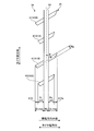
図5~図9は、図4に記載したクローズドラグ溝の変形例を示す説明図である。これらの図において、図4に記載した構成要素と同一の構成要素には同一の符号を付し、その説明を省略する。
図5~図9は、図4に記載したクローズドラグ溝の変形例を示す説明図である。これらの図において、図4に記載した構成要素と同一の構成要素には同一の符号を付し、その説明を省略する。
図4の構成では、上記のように、ショルダー陸部35におけるクローズドラグ溝41(41A、41B)の外側終端部が、タイヤ幅方向に位置を揃えて配列されている。このため、クローズドラグ溝41の外側終端部のタイヤ幅方向のオフセット量ΔDoがゼロである。
これに対して、図5の構成では、ショルダー陸部35におけるクローズドラグ溝41(41A、41B)の外側終端部が、タイヤ幅方向に相互に若干オフセットして配列されている。具体的には、クローズドラグ溝41の外側終端部のオフセット量ΔDoが、ショルダー陸部35の接地幅W2に対して所定の範囲内でゼロにならないように設定されている。かかる構成としても、ショルダー陸部35の剛性を適正に確保できる。
また、図6の構成では、図4の構成とは対称的に、クローズドラグ溝41(41A、41B)の終端部が、セカンド陸部34内でタイヤ幅方向に位置を揃えて配列され、ショルダー陸部35内でタイヤ幅方向にオフセットして配列されている。この場合には、クローズドラグ溝41の内側終端部のオフセット量ΔDiが、セカンド陸部34の接地幅W1に対して、0≦ΔDi/W1≦0.05の関係を有し、また、クローズドラグ溝41の外側終端部のオフセット量ΔDoが、ショルダー陸部35の接地幅W2に対して、0.10≦ΔDo/W2≦0.60の関係を有することが好ましい。
また、図7の構成では、図4および図6の構成とは異なり、クローズドラグ溝41(41A、41B)のタイヤ幅方向の中心位置を揃えて配列されている。この場合には、クローズドラグ溝41のタイヤ幅方向の中心点と周方向細溝24の溝中心線との距離(図示省略)が、周方向細溝24の溝幅Wsに対して50[%]以下の範囲にあることが好ましい。すなわち、クローズドラグ溝41のタイヤ幅方向の中心点が周方向細溝24の内部にあることが好ましい。
また、図4の構成では、上記のように、相互に異なる長さをもつ2種類のクローズドラグ溝41A、41Bがタイヤ周方向に交互に配列されている。また、クローズドラグ溝41(41A、41B)の総数がショルダーラグ溝42の総数の2倍であり、また、長尺なクローズドラグ溝41Bの総数がショルダーラグ溝42の総数と同一に設定されている(図3参照)。
しかし、これに限らず、図8に示すように、相互に異なる長さをもつ3種類のクローズドラグ溝41A~41Cがタイヤ周方向に所定の配列順序で配列されても良い。例えば、図8の構成では、クローズドラグ溝41A~41Cが、同図の下方から上方に向かって、短尺、中尺、長尺の順に繰り返し配列されている。また、最も短尺なクローズドラグ溝41Aの延在長さL1_minと最も長尺なクローズドラグ溝41Bの延在長さL1_maxと(図3参照)が1.10≦L1_max/L1_min≦3.00の関係を有するように設定されている。また、クローズドラグ溝41(41A~41C)の総数がショルダーラグ溝42の総数の3倍であり、また、長尺なクローズドラグ溝41Bの総数がショルダーラグ溝42の総数と同一に設定されることが好ましい。これにより、ショルダーラグ溝42が、長尺なクローズドラグ溝41Bに一対一で対応して、長尺なクローズドラグ溝41Bの溝中心線の延長線上に配置できる。
また、図9に示すように、図8における中尺なクローズドラグ溝41Cが短尺なクローズドラグ溝41Aと同一の延在長さを有することにより、同一の延在長さをもつ短尺かつ一対のクローズドラグ溝41Aが隣り合う長尺なクローズドラグ溝41B、41Bの間に配列されても良い。
[効果]
以上説明したように、この空気入りタイヤ10は、タイヤ赤道面CLを境界とする一方の領域(図2では、車幅方向外側領域)に配置された周方向主溝23と、周方向主溝23のタイヤ幅方向外側に配置された周方向細溝24と、周方向主溝23および周方向細溝24に区画されたショルダー陸部35およびセカンド陸部34とを備える(図2参照)。また、空気入りタイヤ10は、タイヤ幅方向に延在して周方向細溝24を貫通し、タイヤ幅方向における内側終端部をセカンド陸部34内に有すると共に外側終端部をショルダー陸部35内に有する複数のクローズドラグ溝41(41A、41B)を備える(図3参照)。また、最も短尺な第一のクローズドラグ溝41Aのタイヤ幅方向の延在長さL1_minと、最も長尺な第二のクローズドラグ溝41Bのタイヤ幅方向の延在長さL1_maxとが、1.10≦L1_max/L1_min≦3.00の関係を有する。
以上説明したように、この空気入りタイヤ10は、タイヤ赤道面CLを境界とする一方の領域(図2では、車幅方向外側領域)に配置された周方向主溝23と、周方向主溝23のタイヤ幅方向外側に配置された周方向細溝24と、周方向主溝23および周方向細溝24に区画されたショルダー陸部35およびセカンド陸部34とを備える(図2参照)。また、空気入りタイヤ10は、タイヤ幅方向に延在して周方向細溝24を貫通し、タイヤ幅方向における内側終端部をセカンド陸部34内に有すると共に外側終端部をショルダー陸部35内に有する複数のクローズドラグ溝41(41A、41B)を備える(図3参照)。また、最も短尺な第一のクローズドラグ溝41Aのタイヤ幅方向の延在長さL1_minと、最も長尺な第二のクローズドラグ溝41Bのタイヤ幅方向の延在長さL1_maxとが、1.10≦L1_max/L1_min≦3.00の関係を有する。
かかる構成では、(1)クローズドラグ溝41が周方向細溝24を貫通することにより、周方向細溝24付近の排水性が向上して、タイヤのウェット性能が向上する。同時に、クローズドラグ溝41が周方向主溝23およびタイヤ接地端Tに開口しないので、周方向細溝24に区画された左右の陸部34、35の剛性が確保される。これらにより、タイヤのウェット性能およびドライ性能が効率的に両立する利点がある。また、(2)相互に異なる延在長さをもつ複数種類のクローズドラグ溝41(41A、41B)がタイヤ周方向に所定間隔で配列されるので、必然的に、少なくとも一方の陸部(図3ではセカンド陸部34)におけるクローズドラグ溝41A、41Bの終端部が、タイヤ幅方向に相互にオフセットしつつタイヤ周方向に配列される。このため、クローズドラグ溝の左右の終端部がタイヤ幅方向の位置を揃えて配列される構成(図示省略)と比較して、長尺なラグ溝部(図3では、第二のクローズドラグ溝41Bのセカンド陸部34側の部分)が1つの陸部(図3では、セカンド陸部34)の踏面に配置され、同時に、幅広な接地領域が隣り合う長尺なラグ溝部の間に形成される。これにより、タイヤのウェット性能およびドライ性能が効率的に向上する利点がある。
また、この空気入りタイヤ10では、周方向細溝24からクローズドラグ溝41(41A、41B)の内側終端部までの距離Diの最小値Di_minおよび最大値Di_max(図4参照)が、1.10≦Di_max/Di_min≦3.00の関係を有する。これにより、セカンド陸部34におけるクローズドラグ溝41A、41Bの内側終端部の位置が適正化されて、タイヤのウェット性能およびドライ性能が両立する利点がある。
また、この空気入りタイヤ10では、クローズドラグ溝41(41A、41B)の内側終端部のタイヤ幅方向のオフセット量ΔDiが、セカンド陸部34の接地幅W1(図3参照)に対して、0.20≦ΔDi/W1≦0.40の関係を有する。これにより、異なる延在長さL1_min、L1_maxをもつ複数種類のクローズドラグ溝41A、41Bを適正に配置できる利点がある。特に、セカンド陸部34は、ウェット性能に対する寄与が大きいため、クローズドラグ溝41A、41Bの終端部がセカンド陸部34でタイヤ幅方向にオフセットして配列されることにより、タイヤのウェット性能が効率的に向上する利点がある。
また、この空気入りタイヤ10では、周方向細溝24からクローズドラグ溝41(41A、41B)の外側終端部までの距離Doの最小値Do_minおよび最大値Do_maxが、0.90≦Do_max/Do_min≦1.10の関係を有する。これにより、ショルダー陸部35の剛性が確保されて、タイヤのドライ制動性能が向上する利点がある。
また、この空気入りタイヤ10では、周方向細溝24からクローズドラグ溝41の内側終端部までの距離Di(図4における距離Diの最小値Di_minおよび最大値Di_maxを含む。)と、セカンド陸部34の接地幅W1(図3参照)とが、0.20≦Di/W1≦0.40の関係を有する。これにより、セカンド陸部34におけるクローズドラグ溝41のタイヤ幅方向への延在長さDiが適正化される利点がある。すなわち、上記下限により、セカンド陸部34内におけるクローズドラグ溝41の延在長さDiが確保されて、クローズドラグ溝41によるウェット性能の向上作用が確保される。また、上記上限により、クローズドラグ溝41の延在長さDiが過大となることに起因するセカンド陸部34の剛性低下が抑制される。
また、この空気入りタイヤ10では、周方向細溝24からクローズドラグ溝41の外側終端部までの距離Do(図4における距離Doの最小値Do_minおよび最大値Do_maxを含む。)と、ショルダー陸部35の接地幅W2(図3参照)とが、0.20≦Do/W2≦0.40の関係を有する。これにより、ショルダー陸部35におけるクローズドラグ溝41のタイヤ幅方向への延在長さが適正化される利点がある。すなわち、上記下限により、ショルダー陸部35内におけるクローズドラグ溝41の延在長さDoが確保されて、クローズドラグ溝41によるウェット性能の向上作用が確保される。また、上記上限により、クローズドラグ溝41の延在長さDoが過大となることに起因するショルダー陸部35の剛性低下が抑制される。
また、この空気入りタイヤ10では、クローズドラグ溝41のタイヤ周方向に対する傾斜角θが、55[deg]≦θ≦75[deg]の範囲にある(図4参照)。これにより、クローズドラグ溝41の排水性が向上する利点があり、また、クローズドラグ溝41に起因するタイヤのパターンノイズが低減される利点がある。
また、この空気入りタイヤ10では、クローズドラグ溝41の溝幅Wgと周方向細溝24の溝幅Wsとが、0.60≦Wg/Ws≦1.00の関係を有する。これにより、クローズドラグ溝41の排水作用が適正に確保される利点がある。
また、この空気入りタイヤ10では、最も幅狭なクローズドラグ溝41の溝幅Wg_minと最も幅広なクローズドラグ溝41の溝幅Wg_max(図示省略)とが、0.90≦Wg_max/Wg_min≦1.10の関係を有する。これにより、陸部の剛性を適正に確保できるので、偏摩耗が抑制される利点がある。
また、この空気入りタイヤ10では、相互に異なる長さをもつ一対のクローズドラグ溝41A、41Bが、タイヤ周方向に交互に配列される(図2参照)。これにより、タイヤのウェット性能およびドライ性能が効率的に両立する利点がある。
また、この空気入りタイヤ10では、ショルダー陸部35が、一方の終端部をショルダー陸部35内に有すると共にタイヤ幅方向に延在してタイヤ接地端Tに開口するショルダーラグ溝42を備える(図2参照)。また、クローズドラグ溝41(図2では、長尺なクローズドラグ溝41B)が、ショルダーラグ溝42の溝中心線の延長線上にある。これにより、ショルダー陸部35の排水性が向上する利点がある。
また、この空気入りタイヤ10では、ショルダー陸部35が、一方の終端部をショルダー陸部35内に有すると共にタイヤ幅方向に延在してタイヤ接地端Tに開口するショルダーラグ溝42を備える(図2参照)。また、クローズドラグ溝41の溝中心線が、ショルダーラグ溝42の溝中心線に対してタイヤ周方向にオーバーラップしない。これにより、ラグ溝のオーバーラップに起因するパターンノイズが低減されて、タイヤの静粛性が向上する利点がある。
また、この空気入りタイヤ10では、ショルダーラグ溝42の終端部からショルダーラグ溝42に対向するクローズドラグ溝41の外側終端部までのタイヤ幅方向の距離D2と、ショルダー陸部35の接地幅W2とが、0.30≦D2/W2≦0.50の関係を有する(図3参照)。これにより、タイヤのウェット性能およびドライ性能が両立する利点がある。すなわち、上記下限により、ショルダー陸部35の剛性および接地領域が確保されて、タイヤのドライ性能が確保される。また、上記上限により、クローズドラグ溝41およびショルダーラグ溝42のタイヤ幅方向への延在長さが確保されて、タイヤのウェット性能が確保される。
また、この空気入りタイヤ10では、タイヤ周方向におけるクローズドラグ溝41の配置間隔P1とショルダーラグ溝42の配置間隔P2とが、0.30≦P1/P2≦0.70の関係を有する。これにより、クローズドラグ溝41およびショルダーラグ溝42の配置間隔P1、P2が適正化される利点がある。
また、この空気入りタイヤ10では、前記一方の領域(図2の車幅方向外側領域)を車幅方向外側にして車両に装着すべきことを指定する装着方向表示部(図示省略)を備える。これにより、タイヤのウェット性能およびドライ性を効率的に両立できる利点がある。
図10は、この発明の実施の形態にかかる空気入りタイヤの性能試験の結果を示す図表である。図11は、図10に記載した従来例の試験タイヤを示す説明図である。図12は、図10に記載した比較例の試験タイヤを示す説明図である。
この性能試験では、複数種類の試験タイヤについて、(1)ウェット操縦安定性能、(2)ドライ操縦安定性能および(3)騒音性能に関する評価が行われた。また、タイヤサイズ245/40R18 97Yの試験タイヤがリムサイズ18×8.5Jのリムに組み付けられ、この試験タイヤに230[kPa]の内圧およびJATMAの規定荷重が付与される。また、試験タイヤが、試験車両である乗用車の総輪に装着される。
(1)ウェット操縦安定性能に関する評価では、試験車両が雨天条件下で所定のテストコースを走行し、ラップタイムが計測される。そして、この測定結果に基づいて指数評価が行われる。この評価は、従来例を基準(100)とした指数評価により行われ、その数値が大きいほど好ましい。
(2)ドライ操縦安定性能に関する評価では、試験車両が平坦な周回路を有するドライ路面のテストコースを60[km/h]~100[km/h]で走行する。そして、テストドライバーがレーチェンジ時およびコーナリング時における操舵性ならびに直進時における安定性について官能評価を行う。この評価は従来例を基準(100)とした指数評価により行われ、その数値が大きいほど好ましい。
(3)騒音性能に関する評価では、試験車両が粗い路面を有するテストコースを10[km/h]~20[km/h]で惰性走行し、テストドライバーが車内騒音に関する官能評価を行う。この評価は、従来例を基準(100)とした指数評価により行われ、その数値が大きいほど好ましい。
実施例1~11の試験タイヤは、図1~図3の構成を備え、周方向主溝23および周方方向細溝24と、長尺および短尺な2種類のクローズドラグ溝41A、41Bと、ショルダーラグ溝42とを車幅方向外側領域に備える。また、図2において、トレッド幅TWが200[mm]であり、周方向主溝23の距離Dmが25.0[mm]であり、周方向細溝24の距離Dnが60.0[mm]である。また、図3において、周方向主溝23の溝幅Wmが15.0[mm]であり、周方向細溝24の溝幅Wsが5.0[mm]であり、セカンド陸部34の幅W1が27.0[mm]であり、ショルダー陸部35の幅W2が36.0[mm]である。また、クローズドラグ溝41の配置間隔P1とショルダーラグ溝42の配置間隔P2とがP1/P2=0.50の関係を有する。また、単位ピッチあたりに、短尺および長尺な一対のクローズドラグ溝41A、41Bと1本のショルダーラグ溝42とが配置されている。
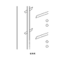
従来例の試験タイヤは、図11に示すように、実施例1の試験タイヤにおける長尺なクローズドラグ溝41Bを備えていない。また、短尺なクローズドラグ溝がショルダーラグ溝の溝中心線の延長線から外れた位置にある。比較例の試験タイヤは、図12に示すように、実施例1の試験タイヤにおけるクローズドラグ溝41A、41Bの延在長さが一定に設定されている。
試験結果に示すように、実施例1~11の試験タイヤでは、タイヤのウェット操縦安定性能、ドライ操縦安定性能および騒音性能が向上することが分かる。
10 空気入りタイヤ;11 ビードコア;12 ビードフィラー;13 カーカス層;14 ベルト層;141、142 交差ベルト;143 ベルトカバー;15 トレッドゴム;16 サイドウォールゴム;17 リムクッションゴム;21~23 周方向主溝;24 周方向細溝;31~35 陸部;41、41A~41C クローズドラグ溝;42 ショルダーラグ溝
Claims (15)
- タイヤ赤道面を境界とする一方の領域に配置された周方向主溝と、前記周方向主溝のタイヤ幅方向外側に配置された周方向細溝と、前記周方向主溝および前記周方向細溝に区画されたショルダー陸部およびセカンド陸部とを備える空気入りタイヤであって、
タイヤ幅方向に延在して前記周方向細溝を貫通し、タイヤ幅方向における内側終端部を前記セカンド陸部内に有すると共に外側終端部を前記ショルダー陸部内に有する複数のクローズドラグ溝を備え、且つ、
最も短尺な第一の前記クローズドラグ溝のタイヤ幅方向の延在長さL1_minと最も長尺な第二の前記クローズドラグ溝のタイヤ幅方向の延在長さL1_maxとが、1.10≦L1_max/L1_min≦3.00の関係を有することを特徴とする空気入りタイヤ。 - 前記周方向細溝から前記クローズドラグ溝の前記内側終端部までの距離Diの最小値Di_minおよび最大値Di_maxが、1.10≦Di_max/Di_min≦3.00の関係を有する請求項1に記載の空気入りタイヤ。
- 前記クローズドラグ溝の前記内側終端部のタイヤ幅方向のオフセット量ΔDiが、前記セカンド陸部の接地幅W1に対して、0.10≦ΔDi/W1≦0.60の関係を有する請求項1または2に記載の空気入りタイヤ。
- 前記周方向細溝から前記クローズドラグ溝の前記外側終端部までの距離Doの最小値Do_minおよび最大値Do_maxが、0.90≦Do_max/Do_min≦1.10の関係を有する請求項1~3のいずれか一つに記載の空気入りタイヤ。
- 前記周方向細溝から前記クローズドラグ溝の前記内側終端部までの距離Diと、前記セカンド陸部の接地幅W1とが、0.10≦Di/W1≦0.80の関係を有する請求項1~4のいずれか一つに記載の空気入りタイヤ。
- 前記周方向細溝から前記クローズドラグ溝の前記外側終端部までの距離Doと、前記ショルダー陸部の接地幅W2とが、0.10≦Do/W2≦0.60の関係を有する請求項1~5のいずれか一つに記載の空気入りタイヤ。
- 前記クローズドラグ溝のタイヤ周方向に対する傾斜角θが、50[deg]≦θ≦80[deg]の範囲にある請求項1~6のいずれか一つに記載の空気入りタイヤ。
- 前記クローズドラグ溝の溝幅Wgと前記周方向細溝の溝幅Wsとが、0.30≦Wg/Ws≦1.30の関係を有する請求項1~7のいずれか一つに記載の空気入りタイヤ。
- 最も幅狭な前記クローズドラグ溝の溝幅Wg_minと最も幅広な前記クローズドラグ溝の溝幅Wg_maxとが、0.90≦Wg_max/Wg_min≦1.10の関係を有する請求項1~8のいずれか一つに記載の空気入りタイヤ。
- 相互に異なる長さをもつ一対の前記クローズドラグ溝が、タイヤ周方向に交互に配列される請求項1~9のいずれか一つに記載の空気入りタイヤ。
- 前記ショルダー陸部が、一方の終端部を前記ショルダー陸部内に有すると共にタイヤ幅方向に延在してタイヤ接地端に開口するショルダーラグ溝を備え、且つ、
前記クローズドラグ溝が、前記ショルダーラグ溝の溝中心線の延長線上にある請求項1~10のいずれか一つに記載の空気入りタイヤ。 - 前記ショルダー陸部が、一方の終端部を前記ショルダー陸部内に有すると共にタイヤ幅方向に延在してタイヤ接地端に開口するショルダーラグ溝を備え、且つ、
前記クローズドラグ溝の溝中心線が、前記ショルダーラグ溝の溝中心線に対してタイヤ周方向にオーバーラップしない請求項1~10のいずれか一つに記載の空気入りタイヤ。 - 前記ショルダーラグ溝の前記終端部から前記ショルダーラグ溝に対向する前記クローズドラグ溝の前記外側終端部までのタイヤ幅方向の距離D2と、前記ショルダー陸部の接地幅W2とが、0.10≦D2/W2≦0.60の関係を有する請求項11または12に記載の空気入りタイヤ。
- タイヤ周方向における前記クローズドラグ溝の配置間隔P1と前記ショルダーラグ溝の配置間隔P2とが、0.30≦P1/P2≦0.70の関係を有する請求項11~13のいずれか一つに記載の空気入りタイヤ。
- 前記一方の領域を車幅方向外側にして車両に装着すべきことを指定する装着方向表示部を備える請求項1~14のいずれか一つに記載の空気入りタイヤ。
Priority Applications (2)
| Application Number | Priority Date | Filing Date | Title |
|---|---|---|---|
| US16/966,418 US12623494B2 (en) | 2018-01-30 | 2018-12-25 | Pneumatic tire |
| CN201880087559.9A CN111655515B (zh) | 2018-01-30 | 2018-12-25 | 充气轮胎 |
Applications Claiming Priority (2)
| Application Number | Priority Date | Filing Date | Title |
|---|---|---|---|
| JP2018-014169 | 2018-01-30 | ||
| JP2018014169A JP6521115B1 (ja) | 2018-01-30 | 2018-01-30 | 空気入りタイヤ |
Publications (1)
| Publication Number | Publication Date |
|---|---|
| WO2019150855A1 true WO2019150855A1 (ja) | 2019-08-08 |
Family
ID=66655666
Family Applications (1)
| Application Number | Title | Priority Date | Filing Date |
|---|---|---|---|
| PCT/JP2018/047683 Ceased WO2019150855A1 (ja) | 2018-01-30 | 2018-12-25 | 空気入りタイヤ |
Country Status (4)
| Country | Link |
|---|---|
| US (1) | US12623494B2 (ja) |
| JP (1) | JP6521115B1 (ja) |
| CN (1) | CN111655515B (ja) |
| WO (1) | WO2019150855A1 (ja) |
Families Citing this family (2)
| Publication number | Priority date | Publication date | Assignee | Title |
|---|---|---|---|---|
| CN116648360A (zh) * | 2020-12-28 | 2023-08-25 | 横滨橡胶株式会社 | 充气轮胎 |
| CN112572065B (zh) * | 2020-12-30 | 2023-03-07 | 赛轮集团股份有限公司 | 一种高操控性非对称花纹轮胎 |
Citations (6)
| Publication number | Priority date | Publication date | Assignee | Title |
|---|---|---|---|---|
| JPH07117417A (ja) * | 1993-10-27 | 1995-05-09 | Sumitomo Rubber Ind Ltd | タイヤのトレッドパターン |
| US20030111149A1 (en) * | 1999-12-01 | 2003-06-19 | Renato Caretta | High and medium performance tyre for vehicles |
| JP2012056479A (ja) * | 2010-09-09 | 2012-03-22 | Yokohama Rubber Co Ltd:The | 空気入りタイヤ |
| JP2012081806A (ja) * | 2010-10-07 | 2012-04-26 | Sumitomo Rubber Ind Ltd | 空気入りタイヤ |
| US20140238568A1 (en) * | 2011-10-03 | 2014-08-28 | Bridgestone Corporation | Pneumatic tire for heavy load |
| JP2016074386A (ja) * | 2014-10-09 | 2016-05-12 | 横浜ゴム株式会社 | 空気入りタイヤ |
Family Cites Families (18)
| Publication number | Priority date | Publication date | Assignee | Title |
|---|---|---|---|---|
| US4529312A (en) | 1981-07-29 | 1985-07-16 | The Board Of Trustees Of The Leland Stanford Junior University | Fiber optic rotation sensor utilizing unpolarized light |
| JP4348321B2 (ja) * | 2005-06-30 | 2009-10-21 | 住友ゴム工業株式会社 | 空気入りタイヤ |
| JP4969874B2 (ja) | 2006-03-06 | 2012-07-04 | 株式会社ブリヂストン | 空気入りタイヤ |
| ATE499221T1 (de) | 2007-07-05 | 2011-03-15 | Pirelli | Reifen für fahrzeuge |
| JP4830005B2 (ja) * | 2009-06-10 | 2011-12-07 | 住友ゴム工業株式会社 | 空気入りタイヤ |
| EP2517901B1 (en) * | 2009-12-25 | 2016-06-15 | Compagnie Générale des Etablissements Michelin | Pneumatic tire tread |
| JP5018981B2 (ja) * | 2010-11-15 | 2012-09-05 | 横浜ゴム株式会社 | 空気入りタイヤ |
| JP5250063B2 (ja) * | 2011-02-28 | 2013-07-31 | 住友ゴム工業株式会社 | 空気入りタイヤ |
| JP5480875B2 (ja) | 2011-11-25 | 2014-04-23 | 住友ゴム工業株式会社 | 空気入りタイヤ |
| JP5617859B2 (ja) | 2012-03-09 | 2014-11-05 | 横浜ゴム株式会社 | 空気入りタイヤ |
| JP6006745B2 (ja) * | 2014-04-30 | 2016-10-12 | 住友ゴム工業株式会社 | 空気入りタイヤ |
| JP6548368B2 (ja) | 2014-07-28 | 2019-07-24 | 株式会社ブリヂストン | 空気入りタイヤ |
| JP6591149B2 (ja) | 2014-08-29 | 2019-10-16 | 株式会社ブリヂストン | 空気入りタイヤ |
| EP3498498B1 (en) * | 2015-01-30 | 2021-03-24 | Bridgestone Corporation | Pneumatic tire |
| JP6424765B2 (ja) * | 2015-07-31 | 2018-11-21 | 横浜ゴム株式会社 | 空気入りタイヤ |
| JP6720551B2 (ja) * | 2016-01-21 | 2020-07-08 | 横浜ゴム株式会社 | 空気入りタイヤ |
| CN206067383U (zh) * | 2016-09-27 | 2017-04-05 | 正新橡胶(中国)有限公司 | 一种充气轮胎 |
| CN106864177B (zh) | 2017-02-24 | 2019-03-26 | 建大橡胶(中国)有限公司 | 一种休旅车非对称花纹轮胎 |
-
2018
- 2018-01-30 JP JP2018014169A patent/JP6521115B1/ja active Active
- 2018-12-25 US US16/966,418 patent/US12623494B2/en active Active
- 2018-12-25 CN CN201880087559.9A patent/CN111655515B/zh active Active
- 2018-12-25 WO PCT/JP2018/047683 patent/WO2019150855A1/ja not_active Ceased
Patent Citations (6)
| Publication number | Priority date | Publication date | Assignee | Title |
|---|---|---|---|---|
| JPH07117417A (ja) * | 1993-10-27 | 1995-05-09 | Sumitomo Rubber Ind Ltd | タイヤのトレッドパターン |
| US20030111149A1 (en) * | 1999-12-01 | 2003-06-19 | Renato Caretta | High and medium performance tyre for vehicles |
| JP2012056479A (ja) * | 2010-09-09 | 2012-03-22 | Yokohama Rubber Co Ltd:The | 空気入りタイヤ |
| JP2012081806A (ja) * | 2010-10-07 | 2012-04-26 | Sumitomo Rubber Ind Ltd | 空気入りタイヤ |
| US20140238568A1 (en) * | 2011-10-03 | 2014-08-28 | Bridgestone Corporation | Pneumatic tire for heavy load |
| JP2016074386A (ja) * | 2014-10-09 | 2016-05-12 | 横浜ゴム株式会社 | 空気入りタイヤ |
Also Published As
| Publication number | Publication date |
|---|---|
| CN111655515A (zh) | 2020-09-11 |
| JP2019131019A (ja) | 2019-08-08 |
| CN111655515B (zh) | 2022-08-05 |
| US12623494B2 (en) | 2026-05-12 |
| JP6521115B1 (ja) | 2019-05-29 |
| US20210039446A1 (en) | 2021-02-11 |
Similar Documents
| Publication | Publication Date | Title |
|---|---|---|
| JP6206517B2 (ja) | 空気入りタイヤ | |
| JP2016074256A (ja) | 空気入りタイヤ | |
| JP2016037276A (ja) | 空気入りタイヤ | |
| WO2016117695A1 (ja) | 空気入りタイヤ | |
| WO2018151108A1 (ja) | 空気入りタイヤ | |
| CN111741857B (zh) | 充气轮胎 | |
| WO2020217964A1 (ja) | 空気入りタイヤ | |
| JP2019137340A (ja) | 空気入りタイヤ | |
| WO2019159544A1 (ja) | 空気入りタイヤ | |
| JP2020183134A (ja) | 空気入りタイヤ | |
| JP7659185B2 (ja) | タイヤ | |
| JP2017065625A (ja) | 空気入りタイヤ | |
| WO2018151111A1 (ja) | 空気入りタイヤ | |
| WO2020008674A1 (ja) | 空気入りタイヤ | |
| US11142025B2 (en) | Pneumatic tire | |
| JP6805535B2 (ja) | 空気入りタイヤ | |
| JP6521115B1 (ja) | 空気入りタイヤ | |
| WO2018012438A1 (ja) | 空気入りタイヤ | |
| JP6780687B2 (ja) | 空気入りタイヤ | |
| JP7115077B2 (ja) | 空気入りタイヤ | |
| US11633988B2 (en) | Pneumatic tire | |
| US11654725B2 (en) | Pneumatic tire | |
| JP2017136954A (ja) | 空気入りタイヤ | |
| JP2019131020A (ja) | 空気入りタイヤ | |
| JP2018034616A (ja) | 空気入りタイヤ |
Legal Events
| Date | Code | Title | Description |
|---|---|---|---|
| 121 | Ep: the epo has been informed by wipo that ep was designated in this application |
Ref document number: 18903695 Country of ref document: EP Kind code of ref document: A1 |
|
| NENP | Non-entry into the national phase |
Ref country code: DE |
|
| 122 | Ep: pct application non-entry in european phase |
Ref document number: 18903695 Country of ref document: EP Kind code of ref document: A1 |