WO2019150460A1 - 車載装置、車車間通信方法、及びコンピュータプログラム - Google Patents
車載装置、車車間通信方法、及びコンピュータプログラム Download PDFInfo
- Publication number
- WO2019150460A1 WO2019150460A1 PCT/JP2018/003080 JP2018003080W WO2019150460A1 WO 2019150460 A1 WO2019150460 A1 WO 2019150460A1 JP 2018003080 W JP2018003080 W JP 2018003080W WO 2019150460 A1 WO2019150460 A1 WO 2019150460A1
- Authority
- WO
- WIPO (PCT)
- Prior art keywords
- vehicle
- communication
- sub
- master
- vehicles
- Prior art date
- Legal status (The legal status is an assumption and is not a legal conclusion. Google has not performed a legal analysis and makes no representation as to the accuracy of the status listed.)
- Ceased
Links
Images





Classifications
-
- G—PHYSICS
- G08—SIGNALLING
- G08G—TRAFFIC CONTROL SYSTEMS
- G08G1/00—Traffic control systems for road vehicles
- G08G1/09—Arrangements for giving variable traffic instructions
Definitions
- the present invention relates to an in-vehicle device, a vehicle-to-vehicle communication method, and a computer program.
- an automatic driving support system shown in Patent Document 1 has already been proposed as a technique for a vehicle that is automatically driving to collect information on other vehicles.
- This automatic driving support system includes a plurality of roadside wireless devices installed along a road and a concentrated base station to which these roadside wireless devices are connected. Information received by road-to-vehicle communication from a vehicle on which one roadside wireless device is automatically traveling is collected by the centralized base station, and another vehicle that is automatically traveling by road-to-vehicle communication from the centralized base station via another roadside wireless device Information is sent to
- the in-vehicle device is an in-vehicle device capable of vehicle-to-vehicle communication, and the sub-master vehicle is configured to receive data of other vehicles received by the sub-master vehicle capable of vehicle-to-vehicle communication with the host vehicle.
- a generation unit that generates transmission request information for requesting transmission to the communication, and communication that transmits the generated transmission request information to the sub-master vehicle by inter-vehicle communication and receives the data transmitted from the sub-master vehicle by inter-vehicle communication.
- a vehicle-mounted device A vehicle-mounted device.
- a vehicle-to-vehicle communication method is a vehicle-to-vehicle communication method performed by an in-vehicle device capable of vehicle-to-vehicle communication, in which a sub-master vehicle capable of vehicle-to-vehicle communication is received by vehicle-to-vehicle communication.
- a vehicle-to-vehicle communication method including: a communication step of receiving the vehicle by vehicle-to-vehicle communication.
- a computer program is a computer program for causing a computer to function as an in-vehicle device capable of vehicle-to-vehicle communication, wherein the computer is a sub-master vehicle capable of vehicle-to-vehicle communication between vehicles. Functions as a generation unit that generates transmission request information for requesting transmission to the sub-master vehicle for data of other vehicles received through communication, and transmits the generated transmission request information to the communication unit by inter-vehicle communication to the sub-master vehicle. It is a computer program to make it.
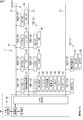
- FIG. 1 is an overall configuration diagram of a communication system according to an embodiment of the present invention. It is a block diagram which shows the structure of a vehicle interior system. It is a block diagram which shows the internal structure of a relay apparatus. It is a block diagram which shows the internal structure of an external communication apparatus. It is explanatory drawing which shows the content and production
- Patent Document 1 ⁇ Problems to be solved by the present disclosure>
- the automatic driving support system of Patent Document 1 requires a plurality of roadside wireless devices, centralized base stations, etc. on the infrastructure side, and collects information on other vehicles existing over a wide area around the host vehicle using this system. Then, the cost becomes considerably high. Then, in view of such a conventional problem, an object is to provide an in-vehicle device or the like that can collect information on other vehicles existing over a wide area around the host vehicle without using infrastructure-side equipment.
- the in-vehicle device is an in-vehicle device capable of vehicle-to-vehicle communication, and the data of other vehicles received by the sub-master vehicle capable of vehicle-to-vehicle communication with the host vehicle through vehicle-to-vehicle communication.
- a generation unit that generates transmission request information for requesting transmission to the sub-master vehicle, the generated transmission request information is transmitted to the sub-master vehicle by inter-vehicle communication, and the data transmitted from the sub-master vehicle is transmitted by inter-vehicle communication.
- a communication unit for receiving is provided.
- the in-vehicle device transmits the transmission request information to a sub-master vehicle capable of inter-vehicle communication with the host vehicle, so that not only the data of the sub-master vehicle but also the sub-master vehicle is Data of other vehicles received by inter-vehicle communication can also be acquired.
- a sub-master vehicle capable of inter-vehicle communication with the host vehicle, so that not only the data of the sub-master vehicle but also the sub-master vehicle is Data of other vehicles received by inter-vehicle communication can also be acquired.
- the in-vehicle device further includes a selection unit that selects the sub-master vehicle from within a predetermined range of a communication area of the own vehicle based on an action plan of the own vehicle.
- a selection unit that selects the sub-master vehicle from within a predetermined range of a communication area of the own vehicle based on an action plan of the own vehicle.
- data of other vehicles related to the action plan of the own vehicle can be acquired from the sub-master vehicle.
- the in-vehicle device further includes a communication link creating unit that creates a communication link indicating a communication path between the other vehicle and the own vehicle with which the own vehicle may collide based on the data. .
- the communication network of the vehicle-to-vehicle communication is established by communicating only with the other vehicles with which the host vehicle may collide. Even if it is enlarged, the burden of communication processing can be reduced. As a result, it is possible to quickly adjust the predicted future driving behavior of the host vehicle and other vehicles.
- the data includes predicted traveling behavior data indicating a predicted traveling behavior of the other vehicle in the future.
- the future predicted driving behavior of the other vehicle can be grasped from the predicted driving behavior data included in the received data.
- the on-vehicle apparatus creates a map for creating a dynamic map in which the future predicted traveling behavior of the host vehicle and the predicted future traveling behavior of the other vehicle included in the predicted traveling behavior data are added to the road map information. It is preferable to further comprise a part. In this case, it is possible to easily grasp the relationship between the predicted future driving behavior of the host vehicle and the predicted driving behavior of the other vehicle from the created dynamic map.
- the said vehicle-mounted apparatus is further provided with the determination part which determines possibility that the own vehicle collides with the said other vehicle based on the created said dynamic map. In this case, it is possible to easily grasp the possibility that the host vehicle will collide with another vehicle based on the determination result of the determination unit.
- a vehicle-to-vehicle communication method is a vehicle-to-vehicle communication method performed by the above-described in-vehicle device. Therefore, the vehicle-to-vehicle communication method of this embodiment has the same effects as the above-described in-vehicle device.
- a computer program according to an embodiment of the present invention is a computer program for causing a computer to function as the above-described in-vehicle device. Therefore, the computer program of this embodiment has the same operational effects as the above-described in-vehicle device.
- FIG. 1 is an overall configuration diagram of a communication system according to an embodiment of the present invention. As shown in FIG. 1, the communication system of the present embodiment includes an out-of-vehicle communication device 19 mounted on each of a plurality of vehicles 1.
- the vehicle exterior communication device 19 is a wireless communication device that performs wireless communication (vehicle-to-vehicle communication) with other vehicles traveling on the road. Therefore, in the present embodiment, the vehicle exterior communication device 19 of the vehicle 1 is also referred to as “vehicle-to-vehicle communication device 19”, and the communication system is also referred to as “vehicle-to-vehicle communication system”. In the present embodiment, the out-of-vehicle communication device 19 employs a multi-access method based on a CSMA / CA (Carrier Sense Multiple Access / Collision Avoidance) method, but other access methods may also be employed.
- CSMA / CA Carrier Sense Multiple Access / Collision Avoidance
- the out-of-vehicle communication device 19 employs a multi-access method in conformity with, for example, “700 MHz band intelligent transportation system standard (ARIB STD-T109)”.
- the vehicle communication apparatus 19 broadcasts a communication frame for inter-vehicle communication every predetermined time (for example, 0.1 second). Therefore, the vehicle 1 that is performing the inter-vehicle communication can detect the vehicle information of the other vehicles around the own vehicle almost in real time by using the communication frame received from the other vehicle included in the radio signal transmission / reception range.
- the communication method of the inter-vehicle communication is not limited to the above-mentioned standard, and may be one in which communication technology for mobile phones such as 3GPP cellular V2V is applied to the wireless communication of the vehicle 1.
- FIG. 2 is a block diagram showing the configuration of the in-vehicle system.
- each vehicle 1 includes an in-vehicle system 10.
- the in-vehicle system 10 includes a relay device 20, a communication network 12, and various in-vehicle devices that are electronically controlled by an ECU belonging to the communication network 12.
- the communication network 12 includes a plurality of in-vehicle communication lines 13 terminating in the relay device 20 and a plurality of in-vehicle control devices (hereinafter referred to as “ECUs”) 16 connected to the in-vehicle communication lines 13.
- the communication network 12 is capable of communication between the ECUs 16 and includes a master / slave type communication network (for example, LIN (Local Interconnect Network)) having the relay device 20 as a terminal node (master unit).
- the relay device 20 controls a plurality of communication networks 12.
- the communication network 12 uses not only LIN but also communication standards such as CAN (Controller Area Network), CANFD (CAN with Flexible Data Rate), Ethernet (registered trademark), or MOST (Media Oriented Systems Transport: MOST is a registered trademark). It may be a network to be adopted. Further, the network configuration of the communication network 12 may include the relay device 20 and at least one ECU 16.
- CAN Controller Area Network
- CANFD CAN with Flexible Data Rate
- Ethernet registered trademark
- MOST Media Oriented Systems Transport: MOST is a registered trademark
- MOST Media Oriented Systems Transport
- the common code of the communication network is “12”, and the individual codes of the communication network are “12A to 12C”. Further, the common code of the ECU is “16”, and the individual codes of the ECU are “16A1 to 16A4”, “16B1 to 16B3”, and “16C1 to 16C2”.
- Each communication network 12A, 12B, 12C shares a different control field of the vehicle 1, respectively.
- a power system ECU that controls a drive device of the vehicle 1 is connected to the communication network 12A.
- the communication network 12B is connected to a multimedia ECU that controls the information device of the vehicle 1.
- Connected to the communication network 12C is an ADAS ECU that controls an Advanced Driver-Assistance System (ADAS) that supports the driving operation of the vehicle 1.
- ADAS Advanced Driver-Assistance System
- the communication network 12 is not limited to the above three types, and may be four or more types. Further, the control field associated with the communication network 12 varies depending on the design philosophy of the vehicle manufacturer, and is not limited to the above-mentioned sharing of the control field.
- the power system ECU connected to the communication network 12A includes, for example, an engine ECU 16A1, an EPS-ECU 16A2, a brake ECU 16A3, an ABS-ECU 16A4, and the like.
- An engine fuel injection device 31 is connected to the engine ECU 16A1, and the fuel injection device 31 is controlled by the engine ECU 16A1.
- An EPS (Electric Power Steering) 32 is connected to the EPS-ECU 16A2, and the EPS 32 is controlled by the EPS-ECU 16A2.
- a brake actuator 33 is connected to the brake ECU 16A3, and the brake actuator 33 is controlled by the brake ECU 16A3.
- An ABS (Antilock Brake System) actuator 34 is connected to the ABS-ECU 16A4, and the ABS actuator 34 is controlled by the ABS-ECU 16A4.
- the multimedia ECU connected to the communication network 12B includes, for example, a navigation ECU 16B1, a meter ECU 16B2, and a HUD-ECU 16B3.
- An HDD (Hard Disk Drive) 41, a display 42, a GPS (Global Positioning System) receiver 43, a vehicle speed sensor 44, a gyro sensor 45, a speaker 46, and an input device 47 are connected to the navigation ECU 16B1.
- the display 42 and the speaker 46 are output devices for presenting various types of information to passengers of the host vehicle. Specifically, the display 42 displays a map image around the host vehicle and route information to the destination, and the speaker 46 outputs an announcement for guiding the host vehicle to the destination.
- the input device 47 is for a passenger to make various inputs such as a destination, and is configured by various input means such as an operation switch, a joystick, or a touch panel provided on the display 42.
- the navigation ECU 16B1 has a time synchronization function for acquiring the current time from the GPS signal periodically acquired by the GPS receiver 43, a position detection function for obtaining the absolute position (latitude, longitude, and altitude) of the host vehicle from the GPS signal,
- the vehicle speed sensor 44 and the gyro sensor 45 have a correction function that corrects the position and direction of the host vehicle to determine the current current position and direction of the host vehicle.
- the navigation ECU 16B1 reads the map information stored in the HDD 41 in accordance with the obtained current position, and generates a map image in which the current position of the host vehicle is superimposed on the map information. Then, the navigation ECU 16B1 displays a map image on the display 42, and displays route information from the current position to the destination on the map image.
- a meter actuator 48 is connected to the meter ECU 16B2, and the meter actuator 48 is controlled by the meter ECU 16B2.
- a HUD (Head-Up Display) 49 is connected to the HUD-ECU 16B3, and the HUD 49 is controlled by the HUD-ECU 16B3.
- Examples of the ADAS ECU connected to the communication network 12C include an ADAS-ECU 16C1, an environment recognition ECU 16C2, and the like.
- a first sensor 51 and a second sensor 52 are connected to the environment recognition ECU 16C2, and the first and second sensors 51 and 52 are controlled by the environment recognition ECU 16C2.
- the 1st sensor 51 consists of ultrasonic sensors, a video camera, etc. which are arranged at four corners of the front, back, left and right of the vehicle 1, for example (see FIG. 1).
- the first sensor 51 provided on the front side is a sensor for mainly detecting an object existing in front of the own vehicle, and the first sensor 51 provided on the rear side is mainly an object existing behind the own vehicle. It is a sensor for detecting.
- the 2nd sensor 52 consists of an ultrasonic sensor, a video camera, etc. which are arrange
- the second sensor 52 is a sensor that can rotate around the vertical axis at a relatively high speed and detects an object existing around the host vehicle.
- the sensing results of the first and second sensors 51 and 52 are stored in a communication packet by the environment recognition ECU 16C2 and transmitted to the ADAS-ECU 16C1.
- the ADAS-ECU 16C1 can execute, for example, any one of automatic driving from level 1 to level 4.
- the level of automatic operation is described in J3016 (September 2016) of SAE (Society of Automotive Engineers) International. “Public-private ITS concept / roadmap 2017” also adopts this definition.
- automatic driving at level 3 or higher is called “highly automatic driving”
- automatic driving at levels 4 and 5 is called “fully automatic driving”.
- Automatic driving in this embodiment means automatic driving at level 2 or higher.
- the ADAS-ECU 16C1 may be capable of performing level 5 automatic driving, but at the time of this application, the vehicle 1 that performs level 5 automatic driving has not yet been realized.
- the possibility of collision is predicted by predicting the possibility of collision from the distance between the object detected by the first sensor 51 and the host vehicle. Some of them transmit a control command to a power system ECU or a multimedia system ECU so as to intervene in a deceleration or alert a passenger when it is determined that the power is high.
- level 4 and 5 automatic driving As an example of level 4 and 5 automatic driving (hereinafter also referred to as “autonomous driving”), the behavior detected by the first and second sensors 51 and 52, the deep learning of past behavior, etc. There is one that transmits a control command to a power system ECU or a multimedia system ECU so that the host vehicle is directed to a target position based on the predicted behavior.
- the ADAS-ECU 16C1 can switch to the passenger's manual operation without using the sensing results of the first and second sensors 51 and 52.
- the vehicle 1 can execute the autonomous driving mode of level 4 and can use the level 1 to 3 support operation mode or the manual operation mode (level 0) as the downgraded operation mode. Either can be performed.
- the operation mode is switched by manual operation input by the passenger.
- the relay device 20 transmits a control packet (hereinafter also referred to as “control command”) to control the ECU 16.
- control command a control packet
- ECU16 performs predetermined control with respect to the object apparatus in charge according to the instruction
- the relay device 20 When controlling the autonomous operation mode, the relay device 20 issues a control command to the ECUs 16A1 to 16A4 of the communication network 12A based on the sensing results of the first and second sensors 51 and 52 received from the environment recognition ECU 16C2. Send the control packet that contains it.
- Each of the ECUs 16A1 to 16A4 that has received the control packet from the relay device 20 controls the fuel injection device 31, the EPS 32, the brake actuator 33, and the ABS actuator 34 in accordance with the contents of the command included in the control packet.
- the mode is executed.
- the in-vehicle system 10 further includes an external communication device 19 that performs wireless communication with other vehicles.
- the vehicle exterior communication device 19 is connected to the relay device 20 through a communication line of a predetermined standard.
- the relay device 20 relays the information received by the external communication device 19 from the other vehicle to the ECU 16.
- the relay device 20 relays information received from the ECU 16 to the vehicle exterior communication device 19.
- the vehicle exterior communication device 19 wirelessly transmits the relayed information to another vehicle.
- the vehicle-mounted communication device 19 mounted on the vehicle 1 may be a device such as a mobile phone, a smartphone, a tablet terminal, or a notebook computer (Personal Computer) owned by the user.
- FIG. 3 is a block diagram showing an internal configuration of the relay device 20.
- the relay device 20 of the vehicle 1 includes a control unit 21, a storage unit 22, an in-vehicle communication unit 23, and the like.
- the control unit 21 of the relay device 20 includes a CPU (Central Processing Unit).
- the CPU of the control unit 21 has a function for reading out one or a plurality of programs stored in the storage unit 22 and executing various processes.
- the CPU of the control unit 21 can execute a plurality of programs in parallel, for example, by switching and executing a plurality of programs in a time division manner.
- the CPU of the control unit 21 includes one or a plurality of large scale integrated circuits (LSIs).
- LSIs large scale integrated circuits
- the plurality of LSIs cooperate to realize the function of the CPU.
- the computer program executed by the CPU of the control unit 21 may be written in advance in a factory, may be provided through a specific tool, or transferred by downloading from a computer device such as a server computer. You can also.
- the storage unit 22 includes a nonvolatile memory element such as a flash memory or an EEPROM (Electrically Erasable Programmable Read Only Memory).
- the storage unit 22 has a storage area for storing a program executed by the CPU of the control unit 21 and data necessary for the execution.
- a plurality of in-vehicle communication lines 13 provided in the vehicle 1 are connected to the in-vehicle communication unit 23.
- the in-vehicle communication unit 23 includes a communication device that communicates with the ECU 16 in accordance with a predetermined communication standard such as LIN.
- the in-vehicle communication unit 23 transmits information given from the CPU of the control unit 21 to a predetermined ECU 16, and the ECU 16 gives information of the transmission source to the CPU of the control unit 21.
- the vehicle exterior communication device 19 transmits the information given from the control unit 21 to the other vehicle and gives the information received from the other vehicle to the control unit 21.
- FIG. 4 is a block diagram showing an internal configuration of the vehicle exterior communication device 19.
- the vehicle exterior communication device 19 includes a control unit 191, a storage unit 192, a wireless communication unit 193, and the like.
- the control unit 191 of the vehicle exterior communication device 19 includes a CPU.
- the CPU of the control unit 191 has a function for reading out one or a plurality of programs stored in the storage unit 192 and executing various processes.
- the CPU of the control unit 191 can execute a plurality of programs in parallel, for example, by switching and executing a plurality of programs in a time division manner.
- the CPU of the control unit 191 includes one or a plurality of large scale integrated circuits (LSIs).
- LSIs large scale integrated circuits
- the plurality of LSIs cooperate to realize the function of the CPU.
- the computer program executed by the CPU of the control unit 191 can be transferred by downloading from a computer device such as a server computer.
- the storage unit 192 includes a nonvolatile memory element such as a flash memory or an EEPROM.
- the storage unit 192 has a storage area for storing programs executed by the CPU of the control unit 191 and data necessary for execution.
- An antenna 194 for wireless communication is connected to the wireless communication unit 193.
- the wireless communication unit 193 transmits the information given from the control unit 191 to the other vehicle from the antenna 194, and gives the information received from the other vehicle by the antenna 194 to the control unit 191.
- the CPU of the control unit 191 transmits the information given from the wireless communication unit 193 to the relay device 20 and gives the information received from the relay device 20 to the wireless communication unit 193.
- FIG. 5 is an explanatory diagram showing the content and generation method of the “predicted travel behavior data D” that the out-of-vehicle communication device 19 transmits to other vehicles through inter-vehicle communication.
- the predicted travel behavior data D is data indicating the predicted travel behavior of the vehicle 1 within the future prediction period Tc for a relatively short predetermined time (for example, 10 seconds) from the present time.
- the predicted traveling behavior data D of the present embodiment is data indicating the predicted traveling behavior of the vehicle 1 at certain time intervals (for example, 300 msec intervals) within the prediction period Tc. Information such as the absolute position and direction of the vehicle 1 is included.
- the time within the prediction period Tc and the absolute position and direction of the vehicle 1 are calculated as follows. For example, in the road plan view shown in the lower part of FIG. 5, when the vehicle 1 is traveling in the lane R1 by automatic driving, the ADAS-ECU 16C1 of the vehicle 1 depends on the content of the automatic driving being executed at the present time t0.
- the planned travel route during the prediction period Tc is calculated, and the calculated planned travel route is transmitted to the external communication device 19.
- the out-of-vehicle communication device 19 performs a map matching process between the received scheduled travel route and map information, and the like, and a plurality of discrete positions (absolute positions) of the vehicle 1 during the prediction period Tc and the direction of the vehicle 1 at each discrete position Is calculated. Specifically, when the vehicle 1 continues to travel straight in the lane R1 during the prediction period Tc, the out-of-vehicle communication device 19 moves along the lane R1 on a straight travel schedule route (an arrow indicated by a broken line in FIG. 5). A plurality of discrete positions (positions indicated by circles in FIG. 5) and directions of the vehicle 1 are calculated at fixed or indefinite time intervals (or distance intervals).
- the out-of-vehicle communication device 19 has a curved traveling schedule route extending from the lanes R1 to the lanes R2 (arrows indicated by a one-dot chain line in FIG. 5). )
- a plurality of discrete positions (positions indicated by ⁇ in FIG. 5) and azimuths of the vehicle 1 are calculated at constant or indefinite time intervals (or distance intervals).
- the out-of-vehicle communication device 19 calculates a time corresponding to each discrete position based on this time interval and the time at the current time t0. Further, when the vehicle exterior communication device 19 calculates a plurality of discrete positions of the vehicle 1 at distance intervals, the vehicle exterior communication device 19 calculates the distance from the current position of the vehicle 1 to each discrete position based on the distance intervals, and calculates the calculated distance and the vehicle. The time corresponding to each discrete position is calculated based on the estimated traveling speed of 1. The estimated traveling speed of the vehicle 1 can be acquired from the ADAS-ECU 16C1. Note that the time within the prediction period Tc and the absolute position and direction of the vehicle 1 may be calculated by the ADAS-ECU 16C1, and the calculated time, discrete position, and direction may be transmitted to the external communication device 19.
- the predicted traveling behavior data D in the present embodiment includes storage areas such as “vehicle ID”, “time”, “absolute position”, “vehicle attribute”, and “direction”.
- “Time” the value of the current time and the value of each time within the prediction period Tc calculated by the above method are stored.
- the value of the current time can be acquired via the relay device 20 from the navigation ECU 16B1 (see FIG. 2) having the time synchronization function.
- Vehicle ID stores the value of the vehicle ID of the host vehicle. Since the value of the vehicle ID is a fixed value, the same value is stored in the “vehicle ID” corresponding to each time.
- the “absolute position” stores latitude, longitude, and altitude values indicating the absolute position of the host vehicle corresponding to each time within the prediction period Tc calculated by the above method.
- “Absolute position” in FIG. 5 shows only latitude and longitude values.
- the “vehicle attribute” stores, for example, values such as the vehicle width and length of the own vehicle, and an identification value of the vehicle application type (such as a private vehicle or emergency vehicle) of the own vehicle. Since the values of the vehicle width, the vehicle length, and the vehicle use type are fixed values, the same value is stored in the “vehicle attribute” corresponding to each time. In “Vehicle attributes” in FIG. 5, specific numerical values are omitted. In “azimuth”, the value of the direction of the host vehicle corresponding to each time within the prediction period Tc calculated by the above method is stored. In “azimuth” in FIG. 5, description of specific numerical values is omitted.
- the own vehicle and other vehicles passing around the vehicle transmit / receive the predicted traveling behavior data D to / from each other by the inter-vehicle communication devices 19 performing inter-vehicle communication.
- the host vehicle and other vehicles passing therearound can share the predicted traveling behavior data D with each other.
- the predicted traveling behavior data D may include other information such as the speed and acceleration of the host vehicle.
- the speed of the own vehicle can be obtained by differentiating the absolute position of the own vehicle
- the acceleration of the own vehicle can be obtained by differentiating the speed obtained from the absolute position of the own vehicle. For this reason, it is not always necessary to include the speed and acceleration of the host vehicle in the predicted traveling behavior data D.
- the external communication device 19 of the present embodiment functions as an in-vehicle device capable of inter-vehicle communication.
- the wireless communication unit (communication unit) 193 of the external communication device 19 transmits data including the predicted traveling behavior data D of the own vehicle to other vehicles located around the own vehicle, and the predicted traveling behavior data D of the other vehicles is transmitted. Receive data including.
- the control unit 191 of the vehicle exterior communication device 19 includes a selection unit 195 and a generation unit 196 that execute a communication network expansion process for expanding a communication network for inter-vehicle communication of the host vehicle.
- the selection unit 195 selects the first sub-master vehicle (sub-master vehicle) from the communication area of the own vehicle (master vehicle) based on the action plan of the own vehicle.
- the first sub-master vehicle is another vehicle that can communicate with the host vehicle.
- the action plan of the own vehicle indicates an action such as a right turn, a left turn, or a lane change that the own vehicle wants to execute, and is input to the control unit 191 before the predicted traveling behavior data D is generated.
- the action plan generated by the ADAS-ECU 16C1 is input to the selection unit 195 via the relay device 20.
- a signal when the driver operates the turn signal is input to the selection unit 195 as the action plan.
- FIG. 6 is a road plan view showing an example of the action plan of the host vehicle.
- the action plan of the own vehicle 1A in FIG. 6 shows an action in which the own vehicle 1A traveling toward the north on the south side road turns to the east side road at the intersection J.
- a process executed by the out-of-vehicle communication device 19 based on the action plan of the host vehicle 1A illustrated in FIG. 6 will be described.
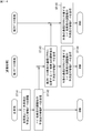
- FIG. 7 is a flowchart showing an example of a processing procedure of communication network expansion processing executed by the vehicle exterior communication device 19 of the host vehicle 1A.
- FIG. 8 is an explanatory diagram showing an example of another vehicle located in the communication area Aa for inter-vehicle communication of the host vehicle 1A. 7 and 8, when the action plan of the host vehicle 1A is input (step ST101), the selection unit 195 of the control unit 191 of the host vehicle 1A (external communication device 19) in the communication area Aa of the host vehicle 1A.
- the predetermined range E for selecting the first sub-master vehicle is determined based on the action plan of the host vehicle (step ST102).
- the selection unit 195 of the present embodiment has an angle range of 180 degrees including the left and right sides and the front side with the host vehicle 1A as the center, and within the communication area Aa. Is determined as a predetermined range E (see FIG. 8). In addition, what is necessary is just to determine the predetermined range E to an appropriate range based on the action plan, when the action plan of the own vehicle 1A is other than a right turn. For example, when the action plan of the host vehicle indicates a lane change to the left side, the selection unit 195 has an angle range of 180 degrees including both the front and rear sides and the left side with respect to the host vehicle and near the outer periphery in the communication area Aa. Is determined as the predetermined range E.
- the selection unit 195 causes the wireless communication unit 193 to receive the predicted travel behavior data D of all other vehicles located in the communication area Aa by inter-vehicle communication (step ST103).
- the wireless communication unit 193 includes the other vehicles 1B, 1C, 1D, 1F, 1H predicted driving behavior data D is received by inter-vehicle communication.
- the selection unit 195 may perform step ST103 before step ST102.
- the selection unit 195 is located within the predetermined range E determined in step ST102 based on the predicted traveling behavior data D of all the other vehicles 1B, 1C, 1D, 1F, and 1H received by the wireless communication unit 193. Identify the vehicle. In the example of FIG. 8, the other vehicles 1 ⁇ / b> F and 1 ⁇ / b> H are specified as other vehicles located within the predetermined range E.
- the selection unit 195 selects, as the first sub-master vehicle, another vehicle that exists at a position suitable for expanding the communication network for inter-vehicle communication from among the identified other vehicles 1F and 1H (step ST104).
- the selection unit 195 selects a plurality of other vehicles positioned at equal intervals along the circumferential direction of the communication area Aa within the predetermined range E as the first sub master vehicle. For example, the selection unit 195 selects three other vehicles located in the directions of 0 degrees, 90 degrees, and 180 degrees within the predetermined range E or in the vicinity thereof as the first sub master vehicle. When there are two other vehicles located within the predetermined range E, if these two other vehicles are located apart from each other within the predetermined range E, both other vehicles are selected as the first sub-master vehicle. May be. In the example of FIG. 8, since the two other specified vehicles 1F and 1H are located apart from each other, the selection unit 195 selects the two other vehicles 1F and 1H as the first sub-master vehicle.
- the selection unit 195 does not always need to select a plurality of other vehicles, and may select at least one other vehicle as the first sub-master vehicle. Moreover, the selection part 195 may select all the other vehicles located in the predetermined range E as a 1st submaster vehicle, or all the other vehicles located in the communication area Aa of the own vehicle are the 1st submaster vehicle. You may choose as
- the generation unit 196 generates first transmission request information (transmission request information) S1 that requests transmission of data to each of the first sub-master vehicles 1F and 1H selected by the selection unit 195, and generates the generated first transmission request information S1.
- the wireless communication part 193 is transmitted (step ST105).
- the data requested to be transmitted to each first sub-master vehicle 1F, 1H is data including predicted traveling behavior data D of other vehicles received by each first sub-master vehicle 1F, 1H through inter-vehicle communication.
- the first transmission request information S1 of the present embodiment includes the vehicle ID of the own vehicle 1A that is the transmission request source, the vehicle ID of the first submaster vehicles 1F and 1H that is the transmission request destination, and the first submaster vehicles 1F and 1H.
- Communication network expansion request information for requesting communication network expansion processing for inter-vehicle communication includes, for example, position information indicating the position of the host vehicle 1A and a radius value r (see FIG. 8) of the virtual circle C centered on the position of the host vehicle 1A.
- the radius value r of the virtual circle C indicates the threshold value of the expansion range of the communication network, and is set according to the situation around the host vehicle 1A.
- the wireless communication unit (communication unit) 193 transmits the first transmission request information S1 generated by the generation unit 196 to the first sub-master vehicles 1F and 1H by inter-vehicle communication.
- the wireless communication unit 193 can receive the data transmitted from the first sub-master vehicles 1F and 1H.
- the first sub-master vehicle 1F, 1H receives the first transmission request information S1 from the own vehicle 1A
- the first sub-master vehicle 1F, 1H receives the data received from all other vehicles (excluding the own vehicle 1A) located in its own communication area. (Step ST106).
- FIG. 9 is an explanatory diagram illustrating an example of another vehicle located in the communication areas Af and Ah for inter-vehicle communication of the first sub-master vehicles 1F and 1H.
- three other vehicles 1E, 1K, 1L are located in the communication area Af of one first sub-master vehicle 1F.
- the 1st submaster vehicle 1F receives the data containing the prediction driving
- the host vehicle 1A receives the data of the other vehicles 1E, 1K, and 1L transmitted from the first sub-master vehicle 1F by the wireless communication unit 193.
- the first sub-master vehicles 1F and 1H determine whether or not to execute communication network expansion processing for inter-vehicle communication based on the communication network expansion request information included in the first transmission request information S1, and the determination If the result is positive, the communication network expansion process is executed.
- one of the first sub-master vehicles 1F is based on the predicted traveling behavior data D included in the data received from all the other vehicles 1E, 1K, 1L located in its communication area Af. The position of each other vehicle 1E, 1K, 1L is grasped. And the 1st submaster vehicle 1F specifies the other vehicle 1K which exists in the position most distant from the position of the own vehicle 1A contained in communication network expansion request information within own communication area Af. The first sub-master vehicle 1F determines whether the position of the identified other vehicle IK is within the range of the virtual circle C determined by the radius value r included in the communication network expansion request information.
- the other first sub-master vehicle 1H is based on predicted traveling behavior data D included in data received from all other vehicles 1B, 1G, 1I, 1J, 1R, 1S, and 1T located in its own communication area Ah. The position of each of these other vehicles 1B, 1G, 1I, 1J, 1R, 1S, 1T is grasped. And the 1st submaster vehicle 1H specifies the other vehicle 1I which exists in the position most distant from the position of the own vehicle 1A contained in communication network expansion request information within the own communication area Ah. The first sub-master vehicle 1H determines whether or not the specified position of the other vehicle II is within the range of the virtual circle C determined by the radius value r included in the communication network expansion request information.
- the first sub-master vehicles 1F and 1H execute the communication network expansion process if the determination result is affirmative, and do not execute the communication network expansion process if the determination result is negative.
- the first sub master vehicles 1F, 1H execute the process.
- the first sub-master vehicles 1F and 1H select the specified other vehicles 1K and 1I as the second sub-master vehicle (step ST107). Then, the first sub master vehicles 1F and 1H generate second transmission request information S2 for requesting data transmission to the selected second sub master vehicles 1K and 1I, and the generated second transmission request information S2 is used as the second sub master vehicle 1K. , 1I (step ST108).
- the data requested to be transmitted to the second sub-master vehicles 1K, 1I includes the predicted traveling behavior data D of other vehicles received by the second sub-master vehicles 1K, 1I through inter-vehicle communication.
- the second transmission request information S2 of the present embodiment includes the vehicle ID of the own vehicle 1A that is the transmission request source, the vehicle ID of the second submaster vehicles 1K and 1I that is the transmission request destination, and the second submaster vehicles 1K and 1I.
- the second sub master vehicles 1K and 1I receive the second transmission request information S2 from the first sub master vehicles 1F and 1H, respectively, all the other vehicles (except for the first sub master vehicles 1F and 1H) located in their communication areas. ) Is transmitted to the first sub-master vehicles 1F and 1H (step ST109).
- FIG. 10 is an explanatory diagram illustrating an example of another vehicle located in the communication areas Ak and Ai for inter-vehicle communication of the second sub-master vehicles 1K and 1I.
- six other vehicles 1E, 1L, 1M, 1N, 1O, 1P are located in the communication area Ak of one second sub-master vehicle 1K.
- the second sub-master vehicle 1K receives data including the predicted traveling behavior data D of the other vehicles 1E, 1L, 1M, 1N, 1O, and 1P
- the first sub-master vehicle 1F receives these data by inter-vehicle communication.
- the second sub-master vehicle 1K includes the vehicle ID of the second sub-master vehicle 1K as the transmission source and the vehicle ID of the own vehicle 1A as the transmission destination in the data to be transmitted.
- the second sub-master vehicle 1I receives the data including the predicted traveling behavior data D of each of the other vehicles 1G, 1J, 1Q, 1R, 1S, and 1T
- the first sub-master vehicle 1H receives these data through inter-vehicle communication.
- the second sub-master vehicle 1I includes the vehicle ID of the second sub-master vehicle 1I as the transmission source and the vehicle ID of the own vehicle 1A as the transmission destination in the data to be transmitted.
- the first sub-master vehicles 1F and 1H When the first sub-master vehicles 1F and 1H receive the data transmitted by the second sub-master vehicles 1K and 1I, the first sub-master vehicles 1F and 1H confirm the vehicle ID of the transmission destination (own vehicle 1A) included in the data, and send the data to the own vehicle 1A. Transmit (step ST110). Thus, the host vehicle 1A receives the data from the second sub-master vehicles 1K and 1I transmitted by the first sub-master vehicles 1F and 1H by the wireless communication unit 193.
- the data transmitted from the second sub-master vehicles 1K, 1I to the first sub-master vehicles 1F, 1H may not include the vehicle ID of the host vehicle 1A that is the transmission destination.
- the first sub-master vehicles 1F and 1H may be set to perform processing for automatically transmitting data received from the second sub-master vehicles 1K and 1I to the host vehicle 1A.
- the second sub-master vehicles 1K and 1I determine whether or not to execute the communication network expansion process for inter-vehicle communication based on the communication network expansion request information included in the second transmission request information S2, and the determination result is affirmative. If it is appropriate, a communication network expansion process is executed.
- one second sub-master vehicle 1K has predicted traveling behavior data D included in data received from all other vehicles 1E, 1L, 1M, 1N, 1O, 1P located in its own communication area Ak. Based on the above, the positions of these other vehicles 1E, 1L, 1M, 1N, 1O, 1P are grasped. And the 2nd submaster vehicle 1K specifies the other vehicle 1P which exists in the position most distant from the position of the own vehicle 1A contained in communication network expansion request information in own communication area Ak. The second sub-master vehicle 1K determines whether or not the position of the specified other vehicle IP is within the range of the virtual circle C determined by the radius value r included in the communication network expansion request information.
- the other second sub-master vehicle 1I is based on the predicted traveling behavior data D included in the data received from all other vehicles other vehicles 1G, 1J, 1Q, 1R, 1S, 1T located within its own communication area Ai. The position of each of these other vehicles 1G, 1J, 1Q, 1R, 1S, 1T is grasped. Then, the second sub-master vehicle 1I specifies the other vehicle 1Q present in the position farthest from the position of the host vehicle 1A included in the communication network expansion request information in its own communication area Ai. The second sub-master vehicle 1I determines whether the position of the identified other vehicle IQ is within the range of the virtual circle C determined by the radius value r included in the communication network expansion request information.
- the second sub-master vehicles 1K and 1I execute the communication network expansion process if the determination result is affirmative, and do not execute the communication network expansion process if the determination result is negative.
- the second sub-master vehicles 1K, 1I Do not execute.
- the vehicle-to-vehicle communication network may be expanded only in the communication area of the first sub-master vehicle, or may be expanded up to the communication area of the n-th sub-master vehicle (n is an integer of 3 or more). Further, the communication network enlargement process in steps ST101 to ST110 may be repeatedly executed periodically.
- the second sub master vehicles 1K and 1I are selected by the first master vehicles 1F and 1H, but may be selected by the own vehicle 1A that is the master vehicle.
- the host vehicle 1A transmits all other vehicles 1E, 1K, 1L, 1B, 1G, 1I, 1J, which are transmitted in the step ST106 and are located in the communication areas Af, Ah of the first master vehicles 1F, 1H.
- 1R, 1S, and 1T data predicted travel behavior data D
- the host vehicle 1A can be selected as the second sub-master vehicle if the other vehicles 1K and 1I existing at the position farthest from the own position are within the range of the virtual circle C. Then, the host vehicle 1A transmits the second transmission request information S2 for requesting data transmission to the second sub master vehicles 1K and 1I to the second sub master vehicles 1K and 1I via the first sub master vehicles 1F and 1H. That's fine. Similarly, the host vehicle 1A may select the n-th sub-master vehicle.
- the host vehicle 1A not only stores the data of the other vehicles 1B to 1D, 1F, and 1H located in its communication area Aa, but also the first submaster.
- Data of other vehicles 1E, 1G, 1I to 1T located in the communication areas Af, Ah of the vehicles 1F, 1H and in the communication areas Ak, Ai of the second sub-master vehicles 1K, 1I can also be acquired. Thereby, the communication network of vehicle-to-vehicle communication can be expanded.
- the control unit 191 of the out-of-vehicle communication device 19 further includes a map creation unit 197, a determination unit 198, and a communication link creation unit 199 that execute a communication link creation process based on the expanded communication network for inter-vehicle communication (see FIG. 4).
- the communication link creation process is a process for creating a communication link L indicating a communication path between another vehicle that may collide with the host vehicle and the host vehicle.
- FIG. 11 is a flowchart showing an example of a processing procedure of communication link creation processing executed by the vehicle exterior communication device 19 of the host vehicle.
- the vehicle-external communication device 19 executes a communication link creation process based on the expanded communication network for inter-vehicle communication shown in FIG.
- the map creation unit 197 of the control unit 191 of the host vehicle 1A includes the host vehicle 1A and the other vehicle on the road map information based on the predicted travel behavior data D.
- a dynamic map M to which the future predicted travel behavior of 1A and the future predicted travel behavior of other vehicles are added is created (step ST121).
- the road map information is included in the map information stored in the HDD 41, and can be acquired from the navigation ECU 16B1 (see FIG. 2) via the relay device 20.
- the predicted traveling behavior data D of the other vehicles As the predicted traveling behavior data D of the other vehicles, the predicted traveling behavior data D of the other vehicles 1B to 1D, 1F, and 1H located in the communication area Aa of the host vehicle 1A and the communication area Af of the first sub-master vehicles 1F and 1H. , Ah and predicted traveling behavior data D of other vehicles 1E, 1G, 1I to 1T located in communication areas Ak, Ai of second sub-master vehicles 1K, 1I are used.
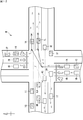
- FIG. 12 is a road plan view showing an example of the dynamic map M created by the map creation unit 197.
- This dynamic map M is road map information indicating the predicted driving behavior of the host vehicle 1A from the current time (solid arrows in the figure) and the predicted driving behavior of the other vehicles 1B to 1T from the current time (broken arrows in the figure). Is added.
- the host vehicle 1A and the other vehicles 1B to 1T show the following predicted traveling behavior near the intersection J. Own vehicle 1A, other vehicle 1C: Turn right from the south road to the east road Other vehicle 1B, 1D: Go straight from the south road to the north road Other vehicle 1E: Go straight from the east road to the west road Other vehicles 1F, 1G , 1H: Go straight from the intersection J to the west road Other vehicles 1S, 1T: Go straight on the west road to the west Other vehicles 1I, 1J, 1Q, 1R: Go straight from the west road to the east side Other vehicles 1K, 1L: East side Go straight east on the other vehicle 1M: Turn right from the north road to the west road Other vehicle 1N: Go straight from the north road to the south road Other vehicles 1O, 1P: Turn left from the north road to the east road
- the map creation unit 197 passes the created dynamic map M to the determination unit 198.
- the determination unit 198 determines the possibility that the host vehicle 1A will collide with the other vehicles 1B to 1T (step ST122). For example, the determination unit 198 determines whether or not the future travel locus of the host vehicle 1A in the dynamic map M and the future travel locus of each of the other vehicles 1B to 1T intersect.
- the determination unit 198 determines that the own vehicle 1A may collide with the other vehicles 1B to 1T when the traveling tracks of the own vehicle 1A and the other vehicles 1B to 1T intersect, and the traveling locus If they do not cross each other, it is determined that there is no possibility that the host vehicle 1A will collide with the other vehicles 1B to 1T.
- the determination unit 198 determines that the own vehicle 1 ⁇ / b> A is the other vehicles 1 ⁇ / b> C, 1 ⁇ / b> E, 1 ⁇ / b> F, 1 ⁇ / b> K, 1 ⁇ / b> L, 1 ⁇ / b> N, 1 ⁇ / b> O, 1 ⁇ / b> P, 1 ⁇ / b> I, 1 ⁇ / b> J, 1 ⁇ / b> Q , 1R, it is determined that there is a possibility of collision.
- the determination unit 198 passes the determination result to the communication link creation unit 199.
- the communication link creation unit 199 determines the other vehicles 1C, 1E, 1F, 1K with which the host vehicle 1A may collide based on the determination result of the determination unit 198 and the communication network of the inter-vehicle communication shown in FIG. , 1L, 1N, 1O, 1P, 1I, 1J, 1Q, 1R and a communication link L indicating the communication path between the host vehicle 1A are created (step ST123).
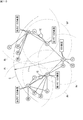
- FIG. 13 is an explanatory diagram illustrating an example of the communication link L created by the communication link creation unit 199. This communication link L is formed by connecting a group of nodes including a plurality of vehicles including the host vehicle 1 ⁇ / b> A through a link capable of inter-vehicle communication.
- the node group includes the own vehicle 1A that is a master vehicle, the other vehicles 1F and 1H that are first submaster vehicles, the other vehicles 1K and 1I that are second submaster vehicles, and the own vehicle other than the first and second submaster vehicles.
- Other vehicles 1C, 1E, 1L, 1N, 1O, 1P, 1J, 1Q, and 1R with which 1A may collide are configured.
- other vehicles with which the host vehicle 1A may collide are indicated by cross hatching.
- other vehicles constituting the node group are also referred to as node other vehicles.
- the communication link creation unit 199 generates node other vehicle information S11 based on the created communication link L, and transmits the generated node other vehicle information S11 to the wireless communication unit 193 (step ST124). ).
- the node other vehicle information S11 includes, for example, the vehicle ID of the own vehicle 1A that is the master vehicle and the vehicle IDs of all the node other vehicles.
- the wireless communication unit 193 transmits the node other vehicle information S11 generated by the communication link creation unit 199 to the first sub master vehicles 1F and 1H.
- the first sub-master vehicle 1F When the first sub-master vehicle 1F receives the node other vehicle information S11 from the host vehicle 1A, the first sub-master vehicle 1F transmits the received node other vehicle information S11 to the second sub-master vehicle 1K.
- the other first sub-master vehicle 1H receives the node other vehicle information S11 from the host vehicle 1A, the other first sub-master vehicle 1H transmits the received node other vehicle information S11 to the second sub-master vehicle 1I (step ST125).
- one of the first sub-master vehicles 1F transmits only data received from the node other vehicles 1E, 1K, 1L located in its own communication area Af to the own vehicle 1A based on the node other vehicle information S11.
- the other first sub-master vehicle 1H transmits only the data received from the node other vehicles 1I, 1J, 1R located in its own communication area Ah to its own vehicle 1A based on the node other vehicle information S11 (step ST126). ).
- the second sub-master vehicles 1K When one of the second sub-master vehicles 1K receives the node other vehicle information S11 from the first sub-master vehicle 1F, the other node other vehicles 1N, 1O, 1O, which are located in its own communication area Ak based on the node other vehicle information S11. Only the data received from 1P is transmitted to the first sub-master vehicle 1F. At that time, the second sub-master vehicle 1K includes the vehicle ID of the second sub-master vehicle 1K as the transmission source and the vehicle ID of the own vehicle 1A as the transmission destination in the data to be transmitted.
- the other second sub-master vehicle 1I When the other second sub-master vehicle 1I receives the node other vehicle information S11 from the first sub-master vehicle 1H, it receives from the node other vehicle 1Q located in its own communication area Ai based on the node other vehicle information S11. Only the data is transmitted to the first sub-master vehicle 1H (step ST127). At that time, the second sub-master vehicle 1I includes the vehicle ID of the second sub-master vehicle 1I as the transmission source and the vehicle ID of the own vehicle 1A as the transmission destination in the data to be transmitted.
- the first sub-master vehicle 1F When the first sub-master vehicle 1F receives the data of the node other vehicles 1N, 1O, 1P transmitted from the second sub-master vehicle 1K, it confirms the vehicle ID of the transmission destination (own vehicle 1A) included in the data. The data is transmitted to the own vehicle 1A.
- the other first sub-master vehicle 1H When the other first sub-master vehicle 1H receives the data of the node other vehicle 1Q transmitted from the second sub-master vehicle 1I, the other first sub-master vehicle 1H confirms the vehicle ID of the transmission destination (own vehicle 1A) included in the data, and stores the data. It transmits to the own vehicle 1A (step ST128).
- the own vehicle 1A receives data of the nodes other vehicles 1N, 1O, 1P, and 1Q transmitted from the first sub-master vehicles 1F and 1H by the wireless communication unit 193.
- the own vehicle transmits / receives data to / from only the other node vehicle, that is, the other vehicle with which the own vehicle may collide among other vehicles connected by the link via the first and second sub-master vehicles. It can be carried out. Thereby, even if the communication network of vehicle-to-vehicle communication expands, the burden of communication processing can be reduced.
- the data transmitted by the second sub-master vehicles 1K, 1I to the first sub-master vehicles 1F, 1H may not include the vehicle ID of the host vehicle 1A that is the transmission destination.
- the first sub-master vehicles 1F and 1H may be set to perform processing for automatically transmitting data received from the second sub-master vehicles 1K and 1I to the host vehicle 1A.
- the communication link expansion process in steps ST121 to ST128 may be repeatedly executed periodically as in the above-described communication network expansion process.
- control unit 191 of the vehicle exterior communication device 19 further includes an adjustment unit 200 that performs adjustment processing of the predicted traveling behavior data D of the host vehicle and other vehicles (see FIG. 4).
- FIG. 14 is a flowchart showing an example of a processing procedure of adjustment processing executed by the vehicle exterior communication device 19 of the host vehicle.
- the out-of-vehicle communication device 19 executes adjustment processing based on the dynamic map M shown in FIG. 12 and the communication link L shown in FIG. 13 will be described.
- the adjustment unit 200 of the control unit 191 of the host vehicle 1A acquires the dynamic map M from the map creation unit 197, and from the communication link creation unit 199.
- the communication link L is acquired.
- the adjustment unit 200 is connected to the other vehicle 1C, 1E, 1L, 1N, 1O, 1P of the other vehicle 1A that may collide with the own vehicle 1A.
- 1J, 1Q, 1R predicted running behavior data D is adjusted (step ST141).
- the adjustment unit 200 performs adjustment processing based on, for example, the position, speed, distance, priority (such as going straight and turning right) of each other node vehicle. Specifically, the adjustment unit 200 first determines the priority for each node other vehicle of the host vehicle 1A. In the example of FIG. 12, the adjusting unit 200 is more suitable for the node other vehicles 1E, 1F, 1N, 1I, 1J, 1Q, and 1R and the node other vehicles 1O and 1P that turn left than the host vehicle 1A that turns right. It is determined that the priority is high.
- the adjustment unit 200 gives priority to the predicted traveling behavior data D of the other nodes 1E, 1F, 1N, 1I, 1J, 1Q, 1R, 1O, and 1P having a high priority based on the determination result.
- the predicted traveling behavior data D of the host vehicle 1A is changed. That is, the adjustment unit 200 causes the node other vehicles 1E, 1F, 1N, 1I, 1J, 1Q, and 1R that go straight forward to pass through the intersection J first, and then turn the node other vehicles 1O and 1P first to the left before the own vehicle.
- the predicted traveling behavior data D of the host vehicle 1A is changed so that 1A makes a right turn.
- the adjusting unit 200 performs the own vehicle 1A and the node other vehicle based on the determination results of the following determinations 1 and 2. Adjustment processing of the predicted traveling behavior data D of 1O and 1P may be performed. Judgment 1: Which lane is scheduled to turn left in each of the other lanes on the east road, which is the left turn destination, of each other vehicle 1O, 1P. Judgment 2: Whether or not the node other vehicles K and L located in the two lanes of the road on the east side are stopped.
- the adjustment unit 200 performs the adjustment process as follows. May be performed. That is, the adjustment unit 200 causes the other vehicles 1O and 1P to turn left in the north lane of the east side road, and turn the own vehicle 1A to the right in the south lane of the east side road.
- the adjustment process of the predicted traveling behavior data D of the vehicles 1O and 1P may be performed.
- the host vehicle 1A may turn right before the node other vehicles 1Q, 1R reach the intersection J.
- the adjustment unit 200 prevents the other vehicles 1Q and 1R from accelerating and turns the own vehicle 1A and the other vehicles 1A and 1R to the right until the other vehicles 1Q and 1R reach the intersection J. You may perform the adjustment process of the prediction driving
- the adjustment unit 200 transmits data including the predicted travel behavior data D after the adjustment process of each other vehicle (hereinafter also referred to as adjustment data) by the wireless communication unit 193. (Step ST142).
- the first sub-master vehicle 1F When the first sub-master vehicle 1F receives the adjustment data from the own vehicle 1A, the first sub-master vehicle 1F confirms the vehicle ID included in the predicted travel behavior data D in the adjustment data. Then, if the node other vehicle corresponding to the confirmed vehicle ID is not located in its own communication area Af, the first sub-master vehicle 1F transmits the adjustment data received from its own vehicle 1A to the second sub-master vehicle 1K. (Step ST143).
- the first sub-master vehicle 1F receives from the own vehicle 1A if the node other vehicle corresponding to the confirmed vehicle ID is any one of the node other vehicles 1E, 1L, 1K located in its own communication area Af.
- the adjusted data is transmitted to the other node vehicles 1E, 1L, 1K (step ST144).
- each node other vehicle 1E, 1L, 1K receives the adjustment data from the first sub-master vehicle 1F, it travels based on the predicted traveling behavior data D in the adjustment data. Further, if the node other vehicle corresponding to the confirmed vehicle ID is itself, the first sub-master vehicle 1F travels based on the predicted travel behavior data D in the adjustment data.
- the other first sub-master vehicle 1H When the other first sub-master vehicle 1H receives the adjustment data from the own vehicle 1A, the other first sub-master vehicle 1H confirms the vehicle ID included in the predicted travel behavior data D in the adjustment data. Then, if the node other vehicle corresponding to the confirmed vehicle ID is not located in its own communication area Ah, the first sub-master vehicle 1H transmits the adjustment data received from its own vehicle 1A to the second sub-master vehicle 1K. (Step ST143).
- the first sub-master vehicle 1H receives from the own vehicle 1A if the node other vehicle corresponding to the confirmed vehicle ID is any one of the node other vehicles 1I, 1J, 1R located in its own communication area Ah.
- the adjusted data is transmitted to the node other vehicles 1I, 1J, 1R (step ST144).
- each node other vehicle 1I, 1J, 1R receives the adjustment data from the first sub-master vehicle 1H, it travels based on the predicted travel behavior data D in the adjustment data.
- the second sub-master vehicle 1K checks the vehicle ID included in the predicted travel behavior data D in the adjustment data. Then, the second sub-master vehicle 1K is the first sub-master vehicle 1F if the node other vehicle corresponding to the confirmed vehicle ID is any one of the node other vehicles 1N, 1O, 1P located in its own communication area Ak. The received adjustment data is transmitted to the other node vehicles 1N, 1O, 1P (step ST145).
- each node other vehicle 1N, 1O, 1P receives the adjustment data from the second sub-master vehicle 1K, it travels based on the predicted travel behavior data D in the adjustment data.
- the second sub-master vehicle 1K travels based on the predicted travel behavior data D in the adjustment data if the node other vehicle corresponding to the confirmed vehicle ID is itself.
- the other second sub-master vehicle 1I When the other second sub-master vehicle 1I receives the adjustment data from the first sub-master vehicle 1H, the other second sub-master vehicle 1I checks the vehicle ID included in the predicted travel behavior data D in the adjustment data. Then, if the node other vehicle corresponding to the confirmed vehicle ID is the node other vehicle 1Q located in its own communication area Ai, the second sub master vehicle 1I uses the adjustment data received from the first sub master vehicle 1H as the node It transmits to the other vehicle 1Q (step ST145).
- the node other vehicle 1Q When the node other vehicle 1Q receives the adjustment data from the second sub-master vehicle 1I, the node other vehicle 1Q travels based on the predicted travel behavior data D in the adjustment data. Moreover, if the node other vehicle corresponding to the confirmed vehicle ID is itself, the second sub-master vehicle 1I travels based on the predicted travel behavior data D in the adjustment data.
- the vehicle communication device 19 transmits the first transmission request information S1 to the first submaster vehicle capable of vehicle-to-vehicle communication with the host vehicle, so that the inter-vehicle communication with the first submaster vehicle.
- the vehicle communication device 19 transmits the first transmission request information S1 to the first submaster vehicle capable of vehicle-to-vehicle communication with the host vehicle, so that the inter-vehicle communication with the first submaster vehicle.
- the communication network of vehicle-to-vehicle communication can be expanded, it is possible to collect information on other vehicles existing over a wide area around the host vehicle without using infrastructure equipment.
- the selection unit 195 selects the first sub-master vehicle from the predetermined range E in the communication area of the own vehicle based on the action plan of the own vehicle. For this reason, the data of the other vehicle related to the action plan of the own vehicle can be acquired from the first sub-master vehicle.
- the communication link creating unit 199 creates a communication link L indicating a communication path between another vehicle with which the own vehicle may collide and the own vehicle, based on the expanded communication network for inter-vehicle communication. For this reason, based on the created communication link L, the first and second sub-master vehicles communicate with only other vehicles with which the host vehicle may collide, among other vehicles with which inter-vehicle communication is performed. Even if the communication network for inter-vehicle communication is expanded, the burden of communication processing can be reduced. As a result, the adjustment process of the predicted traveling behavior data D of the host vehicle and the other vehicle can be quickly performed.
- the data received from another vehicle by the communication network of the expanded vehicle-to-vehicle communication includes the predicted traveling behavior data D indicating the predicted traveling behavior of the other vehicle in the future, from the predicted traveling behavior data D, It is possible to grasp the predicted driving behavior in the future.
- the map creation unit 197 creates a dynamic map M in which the future predicted travel behavior of the host vehicle and the future predicted travel behavior of other vehicles included in the predicted travel behavior data D are added to the road map information. For this reason, it is possible to easily grasp the relationship between the predicted driving behavior of the host vehicle and the predicted driving behavior of the other vehicle from the created dynamic map M.
- the determination unit 198 determines the possibility that the own vehicle will collide with another vehicle based on the created dynamic map M, and therefore, based on the determination result, the possibility that the own vehicle will collide with the other vehicle is determined. It can be easily grasped.
- the out-of-vehicle communication device 19 executes the communication network expansion process, the communication link creation process, and the adjustment process, but may be any apparatus that executes at least the communication network expansion process. Further, in the present embodiment, the out-of-vehicle communication device 19 is an in-vehicle device that executes communication network expansion processing or the like, but the relay device 20 may be an in-vehicle device.
Landscapes
- Physics & Mathematics (AREA)
- General Physics & Mathematics (AREA)
- Traffic Control Systems (AREA)
- Mobile Radio Communication Systems (AREA)
Abstract
車車間通信が可能な車載装置であって、自車両と車車間通信が可能なサブマスタ車両が車車間通信で受信した他車両のデータについて、前記サブマスタ車両に送信要求する送信要求情報を生成する生成部と、生成された前記送信要求情報を車車間通信により前記サブマスタ車両に送信し、前記サブマスタ車両から送信された前記データを車車間通信により受信する通信部と、を備える車載装置。
Description
本発明は、車載装置、車車間通信方法、及びコンピュータプログラムに関する。
近年、自動車の自動運転技術の開発が盛んに行われている。自動車の自動運転を実現するためには、自車両の周囲のできるだけ広範囲にわたって存在する他車両の情報を収集し、他車両との衝突を回避することが重要となる。自動運転中の車両が他車両の情報を収集する技術として、例えば特許文献1に示す自動走行支援システムが既に提案されている。
この自動走行支援システムは、道路に沿って設置された複数の路側無線装置と、これらの路側無線装置が接続された集中基地局とを備えている。一の路側無線装置が自動走行中の車両から路車間通信により受信した情報は集中基地局で収集され、集中基地局から他の路側無線装置を介して路車間通信により他の自動走行中の車両に情報が送信される。
この自動走行支援システムは、道路に沿って設置された複数の路側無線装置と、これらの路側無線装置が接続された集中基地局とを備えている。一の路側無線装置が自動走行中の車両から路車間通信により受信した情報は集中基地局で収集され、集中基地局から他の路側無線装置を介して路車間通信により他の自動走行中の車両に情報が送信される。
本発明の一態様に係る車載装置は、車車間通信が可能な車載装置であって、自車両と車車間通信が可能なサブマスタ車両が車車間通信で受信した他車両のデータについて、前記サブマスタ車両に送信要求する送信要求情報を生成する生成部と、生成された前記送信要求情報を車車間通信により前記サブマスタ車両に送信し、前記サブマスタ車両から送信された前記データを車車間通信により受信する通信部と、を備える車載装置である。
本発明の一態様に係る車車間通信方法は、車車間通信が可能な車載装置が行う車車間通信方法であって、自車両と車車間通信が可能なサブマスタ車両が車車間通信で受信した他車両のデータについて、前記サブマスタ車両に送信要求する送信要求情報を生成する生成ステップと、生成された前記送信要求情報を車車間通信により前記サブマスタ車両に送信し、前記サブマスタ車両から送信された前記データを車車間通信により受信する通信ステップと、を含む車車間通信方法である。
本発明の一態様に係るコンピュータプログラムは、車車間通信が可能な車載装置としてコンピュータを機能させるためのコンピュータプログラムであって、前記コンピュータを、自車両と車車間通信が可能なサブマスタ車両が車車間通信で受信した他車両のデータについて、前記サブマスタ車両に送信要求する送信要求情報を生成し、生成した前記送信要求情報を前記サブマスタ車両に対して車車間通信により通信部に送信させる生成部として機能させるコンピュータプログラムである。
<本開示が解決しようとする課題>
特許文献1の自動走行支援システムでは、インフラ側に複数の路側無線装置や集中基地局等が必要になるため、このシステムを使用して自車両の周囲の広範囲にわたって存在する他車両の情報を収集するとなると、かなりのコスト高となる。
そこで、かかる従来の問題点に鑑み、インフラ側の設備を用いることなく、自車両の周囲の広範囲にわたって存在する他車両の情報を収集することができる車載装置等を提供することを目的とする。
特許文献1の自動走行支援システムでは、インフラ側に複数の路側無線装置や集中基地局等が必要になるため、このシステムを使用して自車両の周囲の広範囲にわたって存在する他車両の情報を収集するとなると、かなりのコスト高となる。
そこで、かかる従来の問題点に鑑み、インフラ側の設備を用いることなく、自車両の周囲の広範囲にわたって存在する他車両の情報を収集することができる車載装置等を提供することを目的とする。
<本開示の効果>
本発明によれば、インフラ側の設備を用いることなく、自車両の周囲の広範囲にわたって存在する他車両の情報を収集することができる。
本発明によれば、インフラ側の設備を用いることなく、自車両の周囲の広範囲にわたって存在する他車両の情報を収集することができる。
<本発明の実施形態の説明>
最初に本発明の実施形態の内容を列記して説明する。
(1)本発明の実施形態に係る車載装置は、車車間通信が可能な車載装置であって、自車両と車車間通信が可能なサブマスタ車両が車車間通信で受信した他車両のデータについて、前記サブマスタ車両に送信要求する送信要求情報を生成する生成部と、生成された前記送信要求情報を車車間通信により前記サブマスタ車両に送信し、前記サブマスタ車両から送信された前記データを車車間通信により受信する通信部と、を備える。
最初に本発明の実施形態の内容を列記して説明する。
(1)本発明の実施形態に係る車載装置は、車車間通信が可能な車載装置であって、自車両と車車間通信が可能なサブマスタ車両が車車間通信で受信した他車両のデータについて、前記サブマスタ車両に送信要求する送信要求情報を生成する生成部と、生成された前記送信要求情報を車車間通信により前記サブマスタ車両に送信し、前記サブマスタ車両から送信された前記データを車車間通信により受信する通信部と、を備える。
前記車載装置は、自車両と車車間通信が可能なサブマスタ車両に対して前記送信要求情報を送信することで、サブマスタ車両との車車間通信により、サブマスタ車両のデータだけでなく、サブマスタ車両が車車間通信で受信した他車両のデータも取得することができる。これにより、車車間通信の通信網を拡大することができるので、インフラ側の設備を用いることなく、自車両の周囲の広範囲にわたって存在する他車両の情報を収集することができる。
(2)前記車載装置は、自車両の行動計画に基づいて、自車両の通信エリアの所定範囲内から前記サブマスタ車両を選択する選択部をさらに備えるのが好ましい。
この場合、例えば、自車両の行動計画に関係する他車両のデータをサブマスタ車両から取得することができる。
この場合、例えば、自車両の行動計画に関係する他車両のデータをサブマスタ車両から取得することができる。
(3)前記車載装置は、前記データに基づいて、自車両が衝突する可能性のある前記他車両と自車両との通信経路を示す通信リンクを作成する通信リンク作成部をさらに備えるのが好ましい。
この場合、作成された通信リンクに基づいて、サブマスタ車両が車車間通信する他車両のうち、自車両が衝突する可能性のある他車両のみと通信を行うことで、車車間通信の通信網が拡大しても、通信処理の負担を軽減することができる。その結果、自車両と他車両の将来の予測走行挙動の調整を迅速に行うことができる。
この場合、作成された通信リンクに基づいて、サブマスタ車両が車車間通信する他車両のうち、自車両が衝突する可能性のある他車両のみと通信を行うことで、車車間通信の通信網が拡大しても、通信処理の負担を軽減することができる。その結果、自車両と他車両の将来の予測走行挙動の調整を迅速に行うことができる。
(4)前記データは、前記他車両の将来の予測走行挙動を示す予測走行挙動データを含むのが好ましい。
この場合、受信したデータに含まれる予測走行挙動データから、他車両の将来の予測走行挙動を把握することができる。
この場合、受信したデータに含まれる予測走行挙動データから、他車両の将来の予測走行挙動を把握することができる。
(5)前記車載装置は、道路地図情報に、自車両の将来の予測走行挙動、及び前記予測走行挙動データに含まれる前記他車両の将来の予測走行挙動を付加したダイナミックマップを作成するマップ作成部をさらに備えるのが好ましい。
この場合、作成されたダイナミックマップから、自車両の将来の予測走行挙動と、他車両の将来の予測走行挙動との関係を容易に把握することができる。
この場合、作成されたダイナミックマップから、自車両の将来の予測走行挙動と、他車両の将来の予測走行挙動との関係を容易に把握することができる。
(6)前記車載装置は、作成された前記ダイナミックマップに基づいて、自車両が前記他車両に衝突する可能性を判定する判定部をさらに備えるのが好ましい。
この場合、判定部の判定結果に基づいて、自車両が他車両に衝突する可能性を容易に把握することができる。
この場合、判定部の判定結果に基づいて、自車両が他車両に衝突する可能性を容易に把握することができる。
(7)本発明の実施形態に係る車車間通信方法は、上述の車載装置が行う車車間通信方法である。従って、本実施形態の車車間通信方法は、上述の車載装置と同様の作用効果を奏する。
(8)本発明の実施形態に係るコンピュータプログラムは、コンピュータを、上述の車載装置として機能させるためのコンピュータプログラムである。従って、本実施形態のコンピュータプログラムは、上述の車載装置と同様の作用効果を奏する。
<本発明の実施形態の詳細>
以下、図面を参照して、本発明の実施形態の詳細を説明する。なお、以下に記載する実施形態の少なくとも一部を任意に組み合わせてもよい。
[通信システムの全体構成]
図1は、本発明の実施形態に係る通信システムの全体構成図である。
図1に示すように、本実施形態の通信システムは、複数の車両1にそれぞれ搭載された車外通信機19を備える。
以下、図面を参照して、本発明の実施形態の詳細を説明する。なお、以下に記載する実施形態の少なくとも一部を任意に組み合わせてもよい。
[通信システムの全体構成]
図1は、本発明の実施形態に係る通信システムの全体構成図である。
図1に示すように、本実施形態の通信システムは、複数の車両1にそれぞれ搭載された車外通信機19を備える。
車外通信機19は、道路を走行中の他車両との間で無線通信(車車間通信)を行う無線通信機である。従って、本実施形態では、車両1の車外通信機19を「車車間通信装置19」ともいい、通信システムを「車車間通信システム」ともいう。
本実施形態では、車外通信機19は、CSMA/CA(Carrier Sense Multiple Access/ Collision Avoidance)方式によるマルチアクセス方式を採用しているが、他のアクセス方式を採用してもよい。
本実施形態では、車外通信機19は、CSMA/CA(Carrier Sense Multiple Access/ Collision Avoidance)方式によるマルチアクセス方式を採用しているが、他のアクセス方式を採用してもよい。
より具体的には、車外通信機19は、例えば「700MHz帯高度道路交通システム標準規格(ARIB STD-T109)」に倣ったマルチアクセス方式を採用している。
この方式によれば、車外通信機19は、車車間通信の通信フレームを所定時間(例えば0.1秒)ごとにブロードキャスト送信する。従って、車車間通信を実行中の車両1は、無線信号の送受信範囲に含まれる他車両から受信した通信フレームにより、自車両の周囲の他車両の車両情報をほぼリアルタイムで察知することができる。
この方式によれば、車外通信機19は、車車間通信の通信フレームを所定時間(例えば0.1秒)ごとにブロードキャスト送信する。従って、車車間通信を実行中の車両1は、無線信号の送受信範囲に含まれる他車両から受信した通信フレームにより、自車両の周囲の他車両の車両情報をほぼリアルタイムで察知することができる。
車車間通信の通信方式は、上記の標準規格に限定されるものではなく、例えば3GPPのセルラーV2Vなど、携帯電話向けの通信技術を車両1の無線通信に応用したものであってもよい。
[車内システムの構成]
図2は、車内システムの構成を示すブロック図である。
図2に示すように、各車両1は、車内システム10を備える。車内システム10は、中継装置20と、通信ネットワーク12と、通信ネットワーク12に属するECUにより電子制御される各種の車載機器とを含む。
図2は、車内システムの構成を示すブロック図である。
図2に示すように、各車両1は、車内システム10を備える。車内システム10は、中継装置20と、通信ネットワーク12と、通信ネットワーク12に属するECUにより電子制御される各種の車載機器とを含む。
通信ネットワーク12は、中継装置20において終端する複数の車内通信線13と、各車内通信線13に接続された複数の車載制御装置(以下、「ECU」という。)16と、を備える。
通信ネットワーク12は、ECU16相互間の通信が可能であり、中継装置20を終端ノード(親機)とするマスター/スレーブ型の通信ネットワーク(例えば、LIN(Local Interconnect Network))よりなる。中継装置20は、複数の通信ネットワーク12を制御する。
通信ネットワーク12は、ECU16相互間の通信が可能であり、中継装置20を終端ノード(親機)とするマスター/スレーブ型の通信ネットワーク(例えば、LIN(Local Interconnect Network))よりなる。中継装置20は、複数の通信ネットワーク12を制御する。
通信ネットワーク12は、LINだけでなく、CAN(Controller Area Network)、CANFD(CAN with Flexible Data Rate)、Ethernet(登録商標)、又はMOST(Media Oriented Systems Transport:MOSTは登録商標)などの通信規格を採用するネットワークであってもよい。
また、通信ネットワーク12のネットワーク構成としては、中継装置20と少なくとも1つのECU16が含まれておればよい。
また、通信ネットワーク12のネットワーク構成としては、中継装置20と少なくとも1つのECU16が含まれておればよい。
以下において、通信ネットワークの共通符号を「12」とし、通信ネットワークの個別符号を「12A~12C」とする。また、ECUの共通符号を「16」とし、ECUの個別符号を「16A1~16A4」、「16B1~16B3」及び「16C1~16C2」とする。
各通信ネットワーク12A,12B,12Cは、車両1の異なる制御分野をそれぞれ分担している。
例えば、通信ネットワーク12Aには、車両1の駆動機器を制御対象とするパワー系ECUが接続されている。通信ネットワーク12Bには、車両1の情報機器を制御対象とするマルチメディア系ECUが接続されている。通信ネットワーク12Cには、車両1の運転操作を支援する先進運転支援システム(ADAS:Advanced Driver-Assistance Systems)を制御対象とするADAS系ECUが接続されている。
例えば、通信ネットワーク12Aには、車両1の駆動機器を制御対象とするパワー系ECUが接続されている。通信ネットワーク12Bには、車両1の情報機器を制御対象とするマルチメディア系ECUが接続されている。通信ネットワーク12Cには、車両1の運転操作を支援する先進運転支援システム(ADAS:Advanced Driver-Assistance Systems)を制御対象とするADAS系ECUが接続されている。
通信ネットワーク12は、上記の3種類に限らず4種類以上であってもよい。また、通信ネットワーク12に対応付ける制御分野は、車両メーカーの設計思想に応じて様々であり、上記の制御分野の分担に限定されるものではない。
具体的には、通信ネットワーク12Aに接続されているパワー系ECUには、例えば、エンジンECU16A1、EPS-ECU16A2、ブレーキECU16A3、及びABS-ECU16A4などが含まれる。
エンジンECU16A1には、エンジンの燃料噴射装置31が接続されており、燃料噴射装置31は、エンジンECU16A1によって制御される。
エンジンECU16A1には、エンジンの燃料噴射装置31が接続されており、燃料噴射装置31は、エンジンECU16A1によって制御される。
EPS-ECU16A2には、EPS(Electric Power Steering:電動パワーステアリング)32が接続されており、EPS32は、EPS-ECU16A2によって制御される。ブレーキECU16A3には、ブレーキアクチュエータ33が接続されており、ブレーキアクチュエータ33は、ブレーキECU16A3によって制御される。
ABS-ECU16A4には、ABS(Antilock Brake System)アクチュエータ34が接続されており、ABSアクチュエータ34は、ABS-ECU16A4によって制御される。
ABS-ECU16A4には、ABS(Antilock Brake System)アクチュエータ34が接続されており、ABSアクチュエータ34は、ABS-ECU16A4によって制御される。
通信ネットワーク12Bに接続されているマルチメディア系ECUには、例えば、ナビゲーションECU16B1、メータECU16B2、及びHUD-ECU16B3などが含まれる。
ナビゲーションECU16B1には、HDD(Hard Disk Drive)41、ディスプレイ42、GPS(Global Positioning System)受信機43、車速センサ44、ジャイロセンサ45、スピーカ46、及び入力デバイス47が接続されている。
ナビゲーションECU16B1には、HDD(Hard Disk Drive)41、ディスプレイ42、GPS(Global Positioning System)受信機43、車速センサ44、ジャイロセンサ45、スピーカ46、及び入力デバイス47が接続されている。
ディスプレイ42とスピーカ46は、各種情報を自車両の搭乗者に提示するための出力装置である。具体的には、ディスプレイ42は、自車両周辺の地図画像及び目的地までの経路情報などを表示し、スピーカ46は、自車両を目的地に誘導するためのアナウンスを音声出力する。
入力デバイス47は、搭乗者が目的地等の各種入力を行うためのものであり、操作スイッチ、ジョイスティック、或いはディスプレイ42に設けたタッチパネル等の各種入力手段により構成される。
入力デバイス47は、搭乗者が目的地等の各種入力を行うためのものであり、操作スイッチ、ジョイスティック、或いはディスプレイ42に設けたタッチパネル等の各種入力手段により構成される。
ナビゲーションECU16B1は、GPS受信機43が定期的に取得したGPS信号から現時点の時刻を取得する時刻同期機能と、GPS信号から自車両の絶対位置(緯度、経度及び高度)を求める位置検出機能と、車速センサ44及びジャイロセンサ45によって自車両の位置及び方位を補正して自車両の正確な現在位置及び方位を求める補正機能などを有する。
ナビゲーションECU16B1は、求めた現在位置に応じてHDD41に格納された地図情報を読み出し、地図情報に自車両の現在位置を重ねた地図画像を生成する。そして、ナビゲーションECU16B1は、ディスプレイ42に地図画像を表示させ、その地図画像に現在位置から目的地までの経路情報などを表示する。
ナビゲーションECU16B1は、求めた現在位置に応じてHDD41に格納された地図情報を読み出し、地図情報に自車両の現在位置を重ねた地図画像を生成する。そして、ナビゲーションECU16B1は、ディスプレイ42に地図画像を表示させ、その地図画像に現在位置から目的地までの経路情報などを表示する。
メータECU16B2には、メータアクチュエータ48が接続されてり、メータアクチュエータ48は、メータECU16B2によって制御される。HUD-ECU16B3には、HUD(Head-Up Display)49が接続されており、HUD49は、HUD-ECU16B3によって制御される。
通信ネットワーク12Cに接続されているADAS系ECUには、例えば、ADAS-ECU16C1、及び環境認識ECU16C2などが含まれる。
環境認識ECU16C2には、第1センサ51及び第2センサ52が接続されており、第1及び第2センサ51,52は、環境認識ECU16C2によって制御される。
環境認識ECU16C2には、第1センサ51及び第2センサ52が接続されており、第1及び第2センサ51,52は、環境認識ECU16C2によって制御される。
第1センサ51は、例えば、車両1の前後左右の四隅に配置された超音波センサやビデオカメラなどよりなる(図1参照)。
前側に設けられた第1センサ51は、主として自車両の前方に存在する物体を検出するためのセンサであり、後側に設けられた第1センサ51は、主として自車両の後方に存在する物体を検出するためのセンサである。
前側に設けられた第1センサ51は、主として自車両の前方に存在する物体を検出するためのセンサであり、後側に設けられた第1センサ51は、主として自車両の後方に存在する物体を検出するためのセンサである。
第2センサ52は、例えば、車両1の天井部分に配置された超音波センサやビデオカメラなどよりなる(図1参照)。第2センサ52は、鉛直軸心回りに比較的高速で回転自在となっており、自車両の周囲に存在する物体を検出するためのセンサである。
第1及び第2センサ51,52のセンシング結果は、環境認識ECU16C2によって通信パケットに格納されてADAS-ECU16C1に送信される。
第1及び第2センサ51,52のセンシング結果は、環境認識ECU16C2によって通信パケットに格納されてADAS-ECU16C1に送信される。
ADAS-ECU16C1は、第1及び第2センサ51,52のセンシング結果に基づいて、例えばレベル1~4までのいずれかの自動運転を実行可能である。自動運転のレベルはSAE(Society of Automotive Engineers)インターナショナルのJ3016(2016年9月)に定義が記載されている。
「官民ITS構想・ロードマップ2017」も当該定義を採用している。このロードマップでは、レベル3以上の自動運転を「高度自動運転」と呼び、レベル4及び5の自動運転を「完全自動運転」と呼ぶ。本実施形態における「自動運転」は、レベル2以上の自動運転を意味する。
「官民ITS構想・ロードマップ2017」も当該定義を採用している。このロードマップでは、レベル3以上の自動運転を「高度自動運転」と呼び、レベル4及び5の自動運転を「完全自動運転」と呼ぶ。本実施形態における「自動運転」は、レベル2以上の自動運転を意味する。
ADAS-ECU16C1は、レベル5の自動運転を実行可能であってもよいが、本出願時点では、レベル5の自動運転を行う車両1は未だ実現されていない。
レベル1~3までの自動運転(以下、「支援運転」ともいう。)の例としては、第1センサ51によって検出した物体と自車両の間の距離から衝突可能性を予測し、衝突可能性が高いと判断した場合に減速介入したり、搭乗者に注意喚起したりするように、パワー系ECUやマルチメディア系ECUに制御指令を送信するものがある。
レベル4及び5の自動運転(以下、「自律運転」ともいう。)の例としては、第1及び第2センサ51,52によって検出した物体に予期される挙動を、過去の挙動の深層学習などにより予測し、予測した挙動に基づいて自車両が目的位置に指向するように、パワー系ECUやマルチメディア系ECUに制御指令を送信するものがある。
ADAS-ECU16C1は、第1及び第2センサ51,52によるセンシング結果を利用せず、搭乗者の手動運転に切り替えることもできる。
このように、本実施形態の車両1は、レベル4の自律運転モードの実行が可能であるとともに、ダウングレードした動作モードとして、レベル1~3の支援運転モード又は手動運転モード(レベル0)のいずれかを実行することができる。動作モードの切り替えは、搭乗者による手動の操作入力などによって行われる。
このように、本実施形態の車両1は、レベル4の自律運転モードの実行が可能であるとともに、ダウングレードした動作モードとして、レベル1~3の支援運転モード又は手動運転モード(レベル0)のいずれかを実行することができる。動作モードの切り替えは、搭乗者による手動の操作入力などによって行われる。
中継装置20は、ECU16を制御するために制御パケット(以下、「制御指令」ともいう。)を送信する。ECU16は、受信した制御パケットに含まれる指令内容に従って、担当する対象機器に対して所定の制御を実行する。
自律運転モードを制御する場合、中継装置20は、環境認識ECU16C2から受信した第1及び第2センサ51,52のセンシング結果に基づいて、通信ネットワーク12Aの各ECU16A1~16A4に対して、制御指令を含む制御パケットを送信する。
そして、中継装置20から制御パケットを受信した各ECU16A1~16A4が、制御パケットに含まれる指令内容に従って、燃料噴射装置31、EPS32、ブレーキアクチュエータ33、及びABSアクチュエータ34をそれぞれ制御することにより、自律運転モードが実行される。
車内システム10は、更に、他車両と無線通信を行う車外通信機19を備える。車外通信機19は、所定規格の通信線を介して中継装置20に接続されている。中継装置20は、他車両から車外通信機19が受信した情報をECU16に中継する。
中継装置20は、ECU16から受信した情報を、車外通信機19に中継する。車外通信機19は、中継された情報を他車両に無線送信する。
車両1に搭載される車外通信機19は、ユーザが所有する携帯電話機、スマートフォン、タブレット型端末、ノートPC(Personal Computer)等の装置であってもよい。
車両1に搭載される車外通信機19は、ユーザが所有する携帯電話機、スマートフォン、タブレット型端末、ノートPC(Personal Computer)等の装置であってもよい。
[中継装置の構成]
図3は、中継装置20の内部構成を示すブロック図である。
図3に示すように、車両1の中継装置20は、制御部21、記憶部22、及び車内通信部23などを備える。
図3は、中継装置20の内部構成を示すブロック図である。
図3に示すように、車両1の中継装置20は、制御部21、記憶部22、及び車内通信部23などを備える。
中継装置20の制御部21は、CPU(Central Processing Unit)を含む。制御部21のCPUは、記憶部22等に記憶された1又は複数のプログラムを読み出して、各種処理を実行するための機能を有している。
制御部21のCPUは、例えば時分割で複数のプログラムを切り替えて実行することにより、複数のプログラムを並列的に実行可能である。
制御部21のCPUは、例えば時分割で複数のプログラムを切り替えて実行することにより、複数のプログラムを並列的に実行可能である。
制御部21のCPUは、1又は複数の大規模集積回路(LSI)を含む。複数のLSIを含むCPUでは、複数のLSIが協働して当該CPUの機能を実現する。
制御部21のCPUが実行するコンピュータプログラムは、予め工場で書き込まれていてもよいし、特定のツールを介して提供されてもよいし、または、サーバコンピュータなどのコンピュータ装置からのダウンロードによって譲渡することもできる。
記憶部22は、フラッシュメモリ若しくはEEPROM(Electrically Erasable Programmable Read Only Memory)などの不揮発性のメモリ素子よりなる。
記憶部22は、制御部21のCPUが実行するプログラム及び実行に必要なデータなどを記憶する記憶領域を有する。
記憶部22は、制御部21のCPUが実行するプログラム及び実行に必要なデータなどを記憶する記憶領域を有する。
車内通信部23には、車両1に配設された複数の車内通信線13が接続されている。車内通信部23は、LINなどの所定の通信規格に則ってECU16と通信する通信装置よりなる。
車内通信部23は、制御部21のCPUから与えられた情報を所定のECU16宛てに送信し、ECU16が送信元の情報を制御部21のCPUに与える。
車外通信機19は、制御部21から与えられた情報を他車両に送信するとともに、他車両から受信した情報を制御部21に与える。
車内通信部23は、制御部21のCPUから与えられた情報を所定のECU16宛てに送信し、ECU16が送信元の情報を制御部21のCPUに与える。
車外通信機19は、制御部21から与えられた情報を他車両に送信するとともに、他車両から受信した情報を制御部21に与える。
[車外通信機の構成]
図4は、車外通信機19の内部構成を示すブロック図である。
図4に示すように、車外通信機19は、制御部191、記憶部192、及び無線通信部193などを備える。
図4は、車外通信機19の内部構成を示すブロック図である。
図4に示すように、車外通信機19は、制御部191、記憶部192、及び無線通信部193などを備える。
車外通信機19の制御部191は、CPUを含む。制御部191のCPUは、記憶部192等に記憶された1又は複数のプログラムを読み出して、各種処理を実行するための機能を有している。
制御部191のCPUは、例えば時分割で複数のプログラムを切り替えて実行することにより、複数のプログラムを並列的に実行可能である。
制御部191のCPUは、例えば時分割で複数のプログラムを切り替えて実行することにより、複数のプログラムを並列的に実行可能である。
制御部191のCPUは、1又は複数の大規模集積回路(LSI)を含む。複数のLSIを含むCPUでは、複数のLSIが協働して当該CPUの機能を実現する。
制御部191のCPUが実行するコンピュータプログラムは、サーバコンピュータなどのコンピュータ装置からのダウンロードによって譲渡することもできる。
記憶部192は、フラッシュメモリ若しくはEEPROMなどの不揮発性のメモリ素子よりなる。
記憶部192は、制御部191のCPUが実行するプログラム及び実行に必要なデータなどを記憶する記憶領域を有する。
記憶部192は、制御部191のCPUが実行するプログラム及び実行に必要なデータなどを記憶する記憶領域を有する。
無線通信部193には、無線通信のためのアンテナ194が接続されている。無線通信部193は、制御部191から与えられた情報をアンテナ194から他車両に送信するとともに、他車両からアンテナ194により受信した情報を制御部191に与える。
制御部191のCPUは、無線通信部193から与えられた情報を中継装置20に送信し、中継装置20から受信した情報を無線通信部193に与える。
制御部191のCPUは、無線通信部193から与えられた情報を中継装置20に送信し、中継装置20から受信した情報を無線通信部193に与える。
[予測走行挙動データの内容及び生成方法]
図5は、車外通信機19が車車間通信により他車両に送信する「予測走行挙動データD」の内容及び生成方法を示す説明図である。予測走行挙動データDは、現時点から比較的短い所定時間(例えば10秒)だけ将来の予測期間Tc内における車両1の予測走行挙動を示すデータである。
図5は、車外通信機19が車車間通信により他車両に送信する「予測走行挙動データD」の内容及び生成方法を示す説明図である。予測走行挙動データDは、現時点から比較的短い所定時間(例えば10秒)だけ将来の予測期間Tc内における車両1の予測走行挙動を示すデータである。
本実施形態の予測走行挙動データDは、予測期間Tc内における一定時間間隔(例えば300m秒間隔)毎の車両1の予測走行挙動を示すデータであり、前記一定時間間隔毎の時刻と、その時刻における車両1の絶対位置及び方位などの情報が含まれる。
予測期間Tc内の時刻と、車両1の絶対位置及び方位は、以下のように算出される。例えば、図5の下段に示す道路平面図において、車両1が車線R1を自動運転で走行している場合、車両1のADAS-ECU16C1は、現時点t0で実行中の自動運転の内容に応じて、予測期間Tc中における走行予定ルートを算出し、算出した走行予定ルートを車外通信機19に送信する。
車外通信機19は、受信した走行予定ルートと地図情報とのマップマッチング処理等を行って、予測期間Tc中における車両1の複数の離散位置(絶対位置)と、各離散位置における車両1の方位を算出する。具体的には、予測期間Tc中において車両1が車線R1を直進し続ける場合、車外通信機19は、車線R1に沿って直線状の走行予定ルート(図5の破線で示す矢印)上において、一定又は不定の時間間隔(又は距離間隔)で、車両1の複数の離散位置(図5の○印で示す位置)及び方位を算出する。
また、予測期間Tc中において車両1が車線R1から車線R2に車線変更する場合、車外通信機19は、車線R1から車線R2へ延びる曲線状の走行予定ルート(図5の1点鎖線で示す矢印)上において、一定又は不定の時間間隔(又は距離間隔)で、車両1の複数の離散位置(図5の△印で示す位置)及び方位を算出する。
車外通信機19は、車両1の複数の離散位置を時間間隔で算出する場合、この時間間隔と現時点t0の時刻に基づいて、各離散位置に対応する時刻を算出する。また、車外通信機19は、車両1の複数の離散位置を距離間隔で算出する場合、この距離間隔に基づいて車両1の現在位置から各離散位置までの距離を算出し、算出した距離と車両1の走行予定速度に基づいて各離散位置に対応する時刻を算出する。車両1の走行予定速度は、ADAS-ECU16C1から取得することができる。
なお、予測期間Tc内の時刻と車両1の絶対位置及び方位は、ADAS-ECU16C1で算出し、算出した時刻、離散位置及び方位を車外通信機19に送信してもよい。
なお、予測期間Tc内の時刻と車両1の絶対位置及び方位は、ADAS-ECU16C1で算出し、算出した時刻、離散位置及び方位を車外通信機19に送信してもよい。
図5の上段に示すように、本実施形態における予測走行挙動データDには、「車両ID」、「時刻」、「絶対位置」、「車両属性」、「方位」などの格納領域が含まれる。
「時刻」には、現時点の時刻の値や上記方法で算出された予測期間Tc内の各時刻の値が格納される。現時点の時刻の値は、上記の時刻同期機能を有するナビゲーションECU16B1(図2参照)から中継装置20を介して取得することができる。
「時刻」には、現時点の時刻の値や上記方法で算出された予測期間Tc内の各時刻の値が格納される。現時点の時刻の値は、上記の時刻同期機能を有するナビゲーションECU16B1(図2参照)から中継装置20を介して取得することができる。
「車両ID」には、自車両の車両IDの値が格納される。車両IDの値は固定値であるため、各時刻に対応する「車両ID」には、全て同じ値が格納される。
「絶対位置」は、上記方法で算出された予測期間Tc内の各時刻に対応する自車両の絶対位置を示す緯度、経度及び高度の各値が格納される。図5の「絶対位置」では、緯度及び経度の値のみを示している。
「絶対位置」は、上記方法で算出された予測期間Tc内の各時刻に対応する自車両の絶対位置を示す緯度、経度及び高度の各値が格納される。図5の「絶対位置」では、緯度及び経度の値のみを示している。
「車両属性」には、例えば、自車両の車幅および車長などの値、および自車両の車両用途種別(自家用車両又は緊急車両など)の識別値が格納される。車幅、車長、及び車両用途種別の各値は固定値であるため、各時刻に対応する「車両属性」には、全て同じ値が格納される。図5の「車両属性」では、具体的な数値の記載を省略している。
「方位」には、上記方法で算出された予測期間Tc内の各時刻に対応する自車両の方位の値が格納される。図5の「方位」では、具体的な数値の記載を省略している。
「方位」には、上記方法で算出された予測期間Tc内の各時刻に対応する自車両の方位の値が格納される。図5の「方位」では、具体的な数値の記載を省略している。
自車両及びその周辺を通行する他車両は、車外通信機19同士が車車間通信を行うことで、予測走行挙動データDを互いに送受信する。これにより、自車両、及びその周辺を通行する他車両が、互いに予測走行挙動データDを共有することができる。
予測走行挙動データDには、自車両の速度や加速度などの他の情報を含めてもよい。但し、自車両の速度は、自車両の絶対位置を微分することで求めることができ、自車両の加速度は、自車両の絶対位置から求めた速度を微分することで求めることができる。このため、予測走行挙動データDには、自車両の速度及び加速度は必ずしも含める必要はない。
[車載装置]
図4において、本実施形態の車外通信機19は、車車間通信が可能な車載装置として機能する。車外通信機19の無線通信部(通信部)193は、自車両の予測走行挙動データDを含むデータを自車両の周辺に位置する他車両に送信し、この他車両の予測走行挙動データDを含むデータを受信する。
図4において、本実施形態の車外通信機19は、車車間通信が可能な車載装置として機能する。車外通信機19の無線通信部(通信部)193は、自車両の予測走行挙動データDを含むデータを自車両の周辺に位置する他車両に送信し、この他車両の予測走行挙動データDを含むデータを受信する。
[車車間通信の通信網拡大処理]
車外通信機19の制御部191は、自車両の車車間通信の通信網を拡大する通信網拡大処理を実行する選択部195及び生成部196を備える。
選択部195は、自車両の行動計画に基づいて、自車両(マスタ車両)の通信エリア内から第1サブマスタ車両(サブマスタ車両)を選択する。第1サブマスタ車両は、自車両と車車間通信が可能な他車両である。
車外通信機19の制御部191は、自車両の車車間通信の通信網を拡大する通信網拡大処理を実行する選択部195及び生成部196を備える。
選択部195は、自車両の行動計画に基づいて、自車両(マスタ車両)の通信エリア内から第1サブマスタ車両(サブマスタ車両)を選択する。第1サブマスタ車両は、自車両と車車間通信が可能な他車両である。
自車両の行動計画は、自車両がこれから実行したい右折、左折、又は車線変更等の行動を示すものであり、予測走行挙動データDが生成される前に制御部191に入力される。例えば、自車両が自動運転で走行している場合には、ADAS-ECU16C1(図2参照)で生成された前記行動計画が、中継装置20を介して選択部195に入力される。また、自車両が手動運転で走行している場合には、運転者がウインカーを操作したときの信号が前記行動計画として選択部195に入力される。
図6は、自車両の行動計画の一例を示す道路平面図である。図6における自車両1Aの行動計画は、南側の道路を北へ向かって走行している自車両1Aが、交差点Jにおいて東側の道路へ右折する行動を示している。以下、本実施形態では、図6に示す自車両1Aの行動計画に基づいて、車外通信機19が実行する処理について説明する。
図7は、自車両1Aの車外通信機19が実行する通信網拡大処理の処理手順の一例を示すフローチャートである。図8は、自車両1Aの車車間通信の通信エリアAa内に位置する他車両の一例を示す説明図である。
図7及び図8において、自車両1A(車外通信機19)の制御部191の選択部195は、自車両1Aの行動計画が入力されると(ステップST101)、自車両1Aの通信エリアAaにおいて、第1サブマスタ車両を選択する所定範囲Eを、自車両の行動計画に基づいて決定する(ステップST102)。
図7及び図8において、自車両1A(車外通信機19)の制御部191の選択部195は、自車両1Aの行動計画が入力されると(ステップST101)、自車両1Aの通信エリアAaにおいて、第1サブマスタ車両を選択する所定範囲Eを、自車両の行動計画に基づいて決定する(ステップST102)。
本実施形態の選択部195は、自車両1Aの行動計画が右折であることから、例えば、自車両1Aを中心として左右両側及び前側を含む180度の角度範囲であって、且つ通信エリアAa内の外周近傍の領域を、所定範囲Eとして決定する(図8参照)。
なお、所定範囲Eは、自車両1Aの行動計画が右折以外の場合には、その行動計画に基づいて適切な範囲に決定すればよい。例えば、自車両の行動計画が左側への車線変更を示す場合、選択部195は、自車両を中心として前後両側及び左側を含む180度の角度範囲であって、且つ通信エリアAa内の外周近傍の領域を、所定範囲Eとして決定すればよい。
なお、所定範囲Eは、自車両1Aの行動計画が右折以外の場合には、その行動計画に基づいて適切な範囲に決定すればよい。例えば、自車両の行動計画が左側への車線変更を示す場合、選択部195は、自車両を中心として前後両側及び左側を含む180度の角度範囲であって、且つ通信エリアAa内の外周近傍の領域を、所定範囲Eとして決定すればよい。
次に、選択部195は、通信エリアAa内に位置する全ての他車両の予測走行挙動データDを、車車間通信により無線通信部193に受信させる(ステップST103)。
図8の例では、通信エリアAa内に、5台の他車両1B,1C,1D,1F,1Hが位置しているため、無線通信部193は、各他車両1B,1C,1D,1F,1Hの予測走行挙動データDを車車間通信により受信する。なお、選択部195は、ステップST103をステップST102よりも先に行ってもよい。
図8の例では、通信エリアAa内に、5台の他車両1B,1C,1D,1F,1Hが位置しているため、無線通信部193は、各他車両1B,1C,1D,1F,1Hの予測走行挙動データDを車車間通信により受信する。なお、選択部195は、ステップST103をステップST102よりも先に行ってもよい。
選択部195は、無線通信部193が受信した前記全ての他車両1B,1C,1D,1F,1Hの予測走行挙動データDに基づいて、前記ステップST102で決定した所定範囲E内に位置する他車両を特定する。図8の例では、他車両1F,1Hが、所定範囲E内に位置する他車両として特定される。選択部195は、特定した他車両1F,1Hのうちから、車車間通信の通信網を拡大するのに適した位置に存在する他車両を第1サブマスタ車両として選択する(ステップST104)。
具体的には、選択部195は、所定範囲E内において通信エリアAaの周方向に沿って等間隔に位置する複数台の他車両を第1サブマスタ車両として選択する。例えば、選択部195は、所定範囲E内の0度、90度、及び180度の各方向又はその近傍に位置する3台の他車両を、第1サブマスタ車両として選択する。また、所定範囲E内に位置する他車両が2台の場合には、これら2台の他車両が所定範囲E内において互いに離れて位置していれば、両他車両を第1サブマスタ車両として選択してもよい。
図8の例では、特定された2台の他車両1F,1Hが互いに離れて位置しているため、選択部195は、2台の他車両1F,1Hを第1サブマスタ車両として選択する。
図8の例では、特定された2台の他車両1F,1Hが互いに離れて位置しているため、選択部195は、2台の他車両1F,1Hを第1サブマスタ車両として選択する。
なお、選択部195は、複数台の他車両を常に選択する必要はなく、少なくとも1台の他車両を第1サブマスタ車両として選択すればよい。また、選択部195は、所定範囲E内に位置する全ての他車両を第1サブマスタ車両として選択してもよいし、自車両の通信エリアAa内に位置する全ての他車両を第1サブマスタ車両として選択してもよい。
生成部196は、選択部195で選択された各第1サブマスタ車両1F,1Hにデータを送信要求する第1送信要求情報(送信要求情報)S1を生成し、生成した第1送信要求情報S1を無線通信部193に送信させる(ステップST105)。各第1サブマスタ車両1F,1Hに送信要求するデータは、各第1サブマスタ車両1F,1Hが車車間通信で受信した他車両の予測走行挙動データDを含むデータである。
本実施形態の第1送信要求情報S1は、送信要求元である自車両1Aの車両IDと、送信要求先である第1サブマスタ車両1F,1Hの車両IDと、第1サブマスタ車両1F,1Hに対して車車間通信の通信網拡大処理を要求する通信網拡大要求情報とを含む。本実施形態の通信網拡大要求情報は、例えば、自車両1Aの位置を示す位置情報と、自車両1Aの位置を中心とする仮想円Cの半径値r(図8参照)とを含む。前記仮想円Cの半径値rは、通信網の拡大範囲の閾値を示しており、自車両1Aの周辺の状況等に応じて設定される。
無線通信部(通信部)193は、生成部196で生成された第1送信要求情報S1を、車車間通信により第1サブマスタ車両1F,1Hに送信する。また、無線通信部193は、第1サブマスタ車両1F,1Hから送信された前記データを受信可能である。
第1サブマスタ車両1F,1Hは、自車両1Aから第1送信要求情報S1を受信すると、自身の通信エリア内に位置する全ての他車両(自車両1Aを除く)から受信したデータを自車両1Aに送信する(ステップST106)。
第1サブマスタ車両1F,1Hは、自車両1Aから第1送信要求情報S1を受信すると、自身の通信エリア内に位置する全ての他車両(自車両1Aを除く)から受信したデータを自車両1Aに送信する(ステップST106)。
図9は、第1サブマスタ車両1F,1Hの車車間通信の通信エリアAf,Ah内に位置する他車両の一例を示す説明図である。
図9において、一方の第1サブマスタ車両1Fの通信エリアAf内には、3台の他車両1E,1K,1Lが位置している。このため、第1サブマスタ車両1Fは、各他車両1E,1K,1Lの予測走行挙動データDを含むデータを受信すると、これらのデータを車車間通信により自車両1Aに送信する。これにより、自車両1Aは、無線通信部193により、第1サブマスタ車両1Fが送信した各他車両1E,1K,1Lのデータを受信する。
図9において、一方の第1サブマスタ車両1Fの通信エリアAf内には、3台の他車両1E,1K,1Lが位置している。このため、第1サブマスタ車両1Fは、各他車両1E,1K,1Lの予測走行挙動データDを含むデータを受信すると、これらのデータを車車間通信により自車両1Aに送信する。これにより、自車両1Aは、無線通信部193により、第1サブマスタ車両1Fが送信した各他車両1E,1K,1Lのデータを受信する。
他方の第1サブマスタ車両1Hの通信エリアAh内には、7台の他車両1B,1G,1I,1J,1R,1S,1Tが位置している。このため、第1サブマスタ車両1Hは、各他車両1B,1G,1I,1J,1R,1S,1Tの予測走行挙動データDを含むデータを受信すると、これらのデータを車車間通信により自車両1Aに送信する。これにより、自車両1Aは、無線通信部193により、第1サブマスタ車両1Hが送信した各他車両1B,1G,1I,1J,1R,1S,1Tのデータを受信する。
次に、第1サブマスタ車両1F,1Hは、第1送信要求情報S1に含まれる通信網拡大要求情報に基づいて、車車間通信の通信網拡大処理を実行するか否かを判定し、その判定結果が肯定的であれば、通信網拡大処理を実行する。
具体的には、一方の第1サブマスタ車両1Fは、自身の通信エリアAf内に位置する全ての他車両1E,1K,1Lから受信したデータに含まれる予測走行挙動データDに基づいて、これらの各他車両1E,1K,1Lの位置を把握する。そして、第1サブマスタ車両1Fは、自身の通信エリアAf内において、通信網拡大要求情報に含まれる自車両1Aの位置から最も離れた位置に存在する他車両1Kを特定する。第1サブマスタ車両1Fは、特定した他車両IKの位置が、通信網拡大要求情報に含まれる半径値rにより定まる仮想円Cの範囲内であるか否かを判定する。
他方の第1サブマスタ車両1Hは、自身の通信エリアAh内に位置する全ての他車両1B,1G,1I,1J,1R,1S,1Tから受信したデータに含まれる予測走行挙動データDに基づいて、これらの各他車両1B,1G,1I,1J,1R,1S,1Tの位置を把握する。そして、第1サブマスタ車両1Hは、自身の通信エリアAh内において、通信網拡大要求情報に含まれる自車両1Aの位置から最も離れた位置に存在する他車両1Iを特定する。第1サブマスタ車両1Hは、特定した他車両IIの位置が、通信網拡大要求情報に含まれる半径値rにより定まる仮想円Cの範囲内であるか否かを判定する。
第1サブマスタ車両1F,1Hは、前記判定結果が肯定的であれば通信網拡大処理を実行し、前記判定結果が否定的であれば通信網拡大処理を実行しない。図9の例では、特定された他車両IK,1Iの位置が仮想円Cの範囲内であるため、つまり前記判定結果は肯定的となるため、第1サブマスタ車両1F,1Hは、通信網拡大処理を実行する。
具体的には、図7及び図9において、第1サブマスタ車両1F,1Hは、前記特定した他車両1K,1Iを第2サブマスタ車両として選択する(ステップST107)。そして、第1サブマスタ車両1F,1Hは、選択した第2サブマスタ車両1K,1Iにデータを送信要求する第2送信要求情報S2を生成し、生成した第2送信要求情報S2を第2サブマスタ車両1K,1Iに送信する(ステップST108)。第2サブマスタ車両1K,1Iに送信要求するデータは、当該第2サブマスタ車両1K,1Iが車車間通信で受信した他車両の予測走行挙動データDを含むものである。
本実施形態の第2送信要求情報S2は、送信要求元である自車両1Aの車両IDと、送信要求先である第2サブマスタ車両1K,1Iの車両IDと、第2サブマスタ車両1K,1Iに対して車車間通信の通信網拡大処理を要求する通信網拡大要求情報とを含む。この通信網拡大要求情報は、第1送信要求情報S1に含まれる通信網拡大要求情報と同じ内容である。
第2サブマスタ車両1K,1Iは、それぞれ第1サブマスタ車両1F,1Hから第2送信要求情報S2を受信すると、自身の通信エリア内に位置する全ての他車両(第1サブマスタ車両1F,1Hを除く)から受信したデータを第1サブマスタ車両1F,1Hに送信する(ステップST109)。
図10は、第2サブマスタ車両1K,1Iの車車間通信の通信エリアAk,Ai内に位置する他車両の一例を示す説明図である。
図10において、一方の第2サブマスタ車両1Kの通信エリアAk内には、6台の他車両1E,1L,1M,1N,1O,1Pが位置している。このため、第2サブマスタ車両1Kは、各他車両1E,1L,1M,1N,1O,1Pの予測走行挙動データDを含むデータを受信すると、これらのデータを車車間通信により第1サブマスタ車両1Fに送信する。その際、第2サブマスタ車両1Kは、送信するデータに、送信元である第2サブマスタ車両1Kの車両IDと、送信先である自車両1Aの車両IDとを含める。
図10において、一方の第2サブマスタ車両1Kの通信エリアAk内には、6台の他車両1E,1L,1M,1N,1O,1Pが位置している。このため、第2サブマスタ車両1Kは、各他車両1E,1L,1M,1N,1O,1Pの予測走行挙動データDを含むデータを受信すると、これらのデータを車車間通信により第1サブマスタ車両1Fに送信する。その際、第2サブマスタ車両1Kは、送信するデータに、送信元である第2サブマスタ車両1Kの車両IDと、送信先である自車両1Aの車両IDとを含める。
他方の第2サブマスタ車両1Iの通信エリアAi内には、6台の他車両1G,1J,1Q,1R,1S,1Tが位置している。このため、第2サブマスタ車両1Iは、各他車両1G,1J,1Q,1R,1S,1Tの予測走行挙動データDを含むデータを受信すると、これらのデータを車車間通信により第1サブマスタ車両1Hに送信する。その際、第2サブマスタ車両1Iは、送信するデータに、送信元である第2サブマスタ車両1Iの車両IDと、送信先である自車両1Aの車両IDとを含める。
第1サブマスタ車両1F,1Hは、第2サブマスタ車両1K,1Iが送信したデータを受信すると、そのデータに含まれる送信先(自車両1A)の車両IDを確認し、当該データを自車両1Aに送信する(ステップST110)。これにより、自車両1Aは、第1サブマスタ車両1F,1Hが送信した、第2サブマスタ車両1K,1Iからのデータを無線通信部193で受信する。
なお、第2サブマスタ車両1K,1Iが第1サブマスタ車両1F,1Hに送信するデータには、送信先である自車両1Aの車両IDを含めなくてもよい。この場合、例えば、第1サブマスタ車両1F,1Hは、第2サブマスタ車両1K,1Iから受信したデータを、自動的に自車両1Aに送信する処理を行うように設定すればよい。
第2サブマスタ車両1K,1Iは、第2送信要求情報S2に含まれる通信網拡大要求情報に基づいて、車車間通信の通信網拡大処理を実行するか否かを判定し、その判定結果が肯定的であれば、通信網拡大処理を実行する。
具体的には、一方の第2サブマスタ車両1Kは、自身の通信エリアAk内に位置する全ての他車両1E,1L,1M,1N,1O,1Pから受信したデータに含まれる予測走行挙動データDに基づいて、これらの各他車両1E,1L,1M,1N,1O,1Pの位置を把握する。そして、第2サブマスタ車両1Kは、自身の通信エリアAk内において、通信網拡大要求情報に含まれる自車両1Aの位置から最も離れた位置に存在する他車両1Pを特定する。第2サブマスタ車両1Kは、特定した他車両IPの位置が、通信網拡大要求情報に含まれる半径値rにより定まる仮想円Cの範囲内であるか否かを判定する。
他方の第2サブマスタ車両1Iは、自身の通信エリアAi内に位置する全ての他車両他車両1G,1J,1Q,1R,1S,1Tから受信したデータに含まれる予測走行挙動データDに基づいて、これらの各他車両1G,1J,1Q,1R,1S,1Tの位置を把握する。そして、第2サブマスタ車両1Iは、自身の通信エリアAi内において、通信網拡大要求情報に含まれる自車両1Aの位置から最も離れた位置に存在する他車両1Qを特定する。第2サブマスタ車両1Iは、特定した他車両IQの位置が、通信網拡大要求情報に含まれる半径値rにより定まる仮想円Cの範囲内であるか否かを判定する。
第2サブマスタ車両1K,1Iは、前記判定結果が肯定的であれば通信網拡大処理を実行し、前記判定結果が否定的であれば通信網拡大処理を実行しない。図10の例では、特定した他車両IP,1Qの位置が仮想円Cの範囲内にないため、つまり前記判定結果は否定的となるため、第2サブマスタ車両1K,1Iは、通信網拡大処理を実行しない。
なお、車車間通信の通信網は、第1サブマスタ車両の通信エリアだけ拡大してもよいし、第nサブマスタ車両(nは3以上の整数)の通信エリアまで拡大してもよい。また、前記ステップST101~ST110の通信網拡大処理は、定期的に繰り返し実行してもよい。
なお、車車間通信の通信網は、第1サブマスタ車両の通信エリアだけ拡大してもよいし、第nサブマスタ車両(nは3以上の整数)の通信エリアまで拡大してもよい。また、前記ステップST101~ST110の通信網拡大処理は、定期的に繰り返し実行してもよい。
また、第2サブマスタ車両1K,1Iは、第1マスタ車両1F,1Hが選択しているが、マスタ車両である自車両1Aが選択してもよい。例えば、自車両1Aは、前記ステップST106で送信された、第1マスタ車両1F,1Hの通信エリアAf,Ah内に位置する全ての他車両1E,1K,1L,1B,1G,1I,1J,1R,1S,1Tのデータ(予測走行挙動データD)を受信することで、これらの他車両1E,1K,1L,1B,1G,1I,1J,1R,1S,1Tの位置を特定することができる。これにより、自車両1Aは、自身の位置から最も離れた位置に存在する他車両1K,1Iが、前記仮想円Cの範囲内であれば、第2サブマスタ車両として選択することができる。そして、自車両1Aは、第2サブマスタ車両1K,1Iにデータを送信要求する第2送信要求情報S2を、第1サブマスタ車両1F,1Hを経由して、第2サブマスタ車両1K,1Iに送信すればよい。同様に、第nサブマスタ車両についても、自車両1Aが選択してもよい。
以上より、本実施形態の通信網拡大処理が実行されることで、自車両1Aは、自身の通信エリアAa内に位置する他車両1B~1D,1F,1Hのデータだけでなく、第1サブマスタ車両1F,1Hの通信エリアAf,Ah内および第2サブマスタ車両1K,1Iの通信エリアAk,Ai内に位置する他車両1E,1G,1I~1Tのデータも取得することができる。これにより、車車間通信の通信網を拡大することができる。
[車車間通信の通信リンクの作成処理]
車外通信機19の制御部191は、拡大された車車間通信の通信網に基づいて、通信リンク作成処理を実行するマップ作成部197、判定部198、及び通信リンク作成部199をさらに備える(図4参照)。通信リンク作成処理は、自車両が衝突する可能性のある他車両と自車両との通信経路を示す通信リンクLを作成する処理である。
車外通信機19の制御部191は、拡大された車車間通信の通信網に基づいて、通信リンク作成処理を実行するマップ作成部197、判定部198、及び通信リンク作成部199をさらに備える(図4参照)。通信リンク作成処理は、自車両が衝突する可能性のある他車両と自車両との通信経路を示す通信リンクLを作成する処理である。
図11は、自車両の車外通信機19が実行する通信リンク作成処理の処理手順の一例を示すフローチャートである。本実施形態では、車外通信機19が、図10に示す拡大した車車間通信の通信網に基づいて、通信リンク作成処理を実行する場合について説明する。
図10及び図11において、自車両1A(車外通信機19)の制御部191のマップ作成部197は、自車両1A及び他車両の予測走行挙動データDに基づいて、道路地図情報に、自車両1Aの将来の予測走行挙動、及び他車両の将来の予測走行挙動を付加したダイナミックマップMを作成する(ステップST121)。
道路地図情報は、HDD41に格納された地図情報に含まれており、ナビゲーションECU16B1(図2参照)から中継装置20を介して取得することができる。
道路地図情報は、HDD41に格納された地図情報に含まれており、ナビゲーションECU16B1(図2参照)から中継装置20を介して取得することができる。
他車両の予測走行挙動データDとしては、自車両1Aの通信エリアAa内に位置する他車両1B~1D,1F,1Hの予測走行挙動データDと、第1サブマスタ車両1F,1Hの通信エリアAf,Ah内および第2サブマスタ車両1K,1Iの通信エリアAk,Ai内に位置する他車両1E,1G,1I~1Tの予測走行挙動データDとが用いられる。
図12は、マップ作成部197が作成したダイナミックマップMの一例を示す道路平面図である。このダイナミックマップMは、自車両1Aの現時点から将来の予測走行挙動(図中の実線矢印)、及び他車両1B~1Tの現時点から将来の予測走行挙動(図中の破線矢印)を道路地図情報に付加したものである。
図12において、自車両1A及び他車両1B~1Tは、交差点J付近において以下の予測走行挙動を示している。
自車両1A,他車両1C:南側の道路から東側の道路へ右折
他車両1B,1D:南側の道路から北側の道路へ直進
他車両1E:東側の道路から西側の道路へ直進
他車両1F,1G,1H:交差点Jから西側の道路へ直進
他車両1S,1T:西側の道路を西へ直進
他車両1I,1J,1Q,1R:西側の道路から東側の道路へ直進
他車両1K,1L:東側の道路を東へ直進
他車両1M:北側の道路から西側の道路へ右折
他車両1N:北側の道路から南側の道路へ直進
他車両1O,1P:北側の道路から東側の道路へ左折
自車両1A,他車両1C:南側の道路から東側の道路へ右折
他車両1B,1D:南側の道路から北側の道路へ直進
他車両1E:東側の道路から西側の道路へ直進
他車両1F,1G,1H:交差点Jから西側の道路へ直進
他車両1S,1T:西側の道路を西へ直進
他車両1I,1J,1Q,1R:西側の道路から東側の道路へ直進
他車両1K,1L:東側の道路を東へ直進
他車両1M:北側の道路から西側の道路へ右折
他車両1N:北側の道路から南側の道路へ直進
他車両1O,1P:北側の道路から東側の道路へ左折
図11及び図12において、マップ作成部197は、作成したダイナミックマップMを判定部198に渡す。判定部198は、ダイナミックマップMに基づいて、自車両1Aが各他車両1B~1Tに衝突する可能性を判定する(ステップST122)。
例えば、判定部198は、ダイナミックマップMにおける自車両1Aの将来の走行軌跡と各他車両1B~1Tの将来の走行軌跡とが交差するか否かを判定する。そして、判定部198は、自車両1A及び各他車両1B~1Tの走行軌跡同士が交わる場合には、自車両1Aが他車両1B~1Tに衝突する可能性があると判定し、当該走行軌跡同士が交わらない場合には、自車両1Aが他車両1B~1Tに衝突する可能性はないと判定する。
例えば、判定部198は、ダイナミックマップMにおける自車両1Aの将来の走行軌跡と各他車両1B~1Tの将来の走行軌跡とが交差するか否かを判定する。そして、判定部198は、自車両1A及び各他車両1B~1Tの走行軌跡同士が交わる場合には、自車両1Aが他車両1B~1Tに衝突する可能性があると判定し、当該走行軌跡同士が交わらない場合には、自車両1Aが他車両1B~1Tに衝突する可能性はないと判定する。
図12の例では、判定部198は、上記判定方向により自車両1Aが、図中のクロスハッチングで示す他車両1C,1E,1F,1K,1L,1N,1O,1P,1I,1J,1Q,1Rにそれぞれ衝突する可能性があると判定する。判定部198は、判定結果を通信リンク作成部199に渡す。
通信リンク作成部199は、判定部198の判定結果、及び図10に示す拡大した車車間通信の通信網に基づいて、自車両1Aが衝突する可能性のある他車両1C,1E,1F,1K,1L,1N,1O,1P,1I,1J,1Q,1Rと自車両1Aとの通信経路を示す通信リンクLを作成する(ステップST123)。
図13は、通信リンク作成部199が作成した通信リンクLの一例を示す説明図である。この通信リンクLは、自車両1Aを含む複数の車両よりなるノード群を、車車間通信が可能なリンクにより接続したものである。
図13は、通信リンク作成部199が作成した通信リンクLの一例を示す説明図である。この通信リンクLは、自車両1Aを含む複数の車両よりなるノード群を、車車間通信が可能なリンクにより接続したものである。
ノード群は、マスタ車両である自車両1Aと、第1サブマスタ車両である他車両1F,1Hと、第2サブマスタ車両である他車両1K,1Iと、第1及び第2サブマスタ車両以外で自車両1Aが衝突する可能性のある他車両1C,1E,1L,1N,1O,1P,1J,1Q,1Rとから構成されている。図13では、自車両1Aが衝突する可能性のある他車両をクロスハッチングで示している。以下、ノード群を構成する他車両を、ノード他車両ともいう。
図11及び図13において、通信リンク作成部199は、作成した通信リンクLに基づいて、ノード他車両情報S11を生成し、生成したノード他車両情報S11を無線通信部193に送信させる(ステップST124)。ノード他車両情報S11は、例えば、マスタ車両である自車両1Aの車両ID、及び全てのノード他車両の車両IDを含む。
無線通信部193は、通信リンク作成部199で生成されたノード他車両情報S11を第1サブマスタ車両1F,1Hに送信する。
無線通信部193は、通信リンク作成部199で生成されたノード他車両情報S11を第1サブマスタ車両1F,1Hに送信する。
一方の第1サブマスタ車両1Fは、自車両1Aからノード他車両情報S11を受信すると、受信したノード他車両情報S11を第2サブマスタ車両1Kに送信する。
他方の第1サブマスタ車両1Hは、自車両1Aからノード他車両情報S11を受信すると、受信したノード他車両情報S11を第2サブマスタ車両1Iに送信する(ステップST125)。
他方の第1サブマスタ車両1Hは、自車両1Aからノード他車両情報S11を受信すると、受信したノード他車両情報S11を第2サブマスタ車両1Iに送信する(ステップST125)。
次に、一方の第1サブマスタ車両1Fは、ノード他車両情報S11に基づいて、自身の通信エリアAf内に位置するノード他車両1E,1K,1Lから受信したデータのみを自車両1Aに送信する。
他方の第1サブマスタ車両1Hは、ノード他車両情報S11に基づいて、自身の通信エリアAh内に位置するノード他車両1I,1J,1Rから受信したデータのみを自車両1Aに送信する(ステップST126)。
他方の第1サブマスタ車両1Hは、ノード他車両情報S11に基づいて、自身の通信エリアAh内に位置するノード他車両1I,1J,1Rから受信したデータのみを自車両1Aに送信する(ステップST126)。
一方の第2サブマスタ車両1Kは、第1サブマスタ車両1Fからノード他車両情報S11を受信すると、そのノード他車両情報S11に基づいて、自身の通信エリアAk内に位置するノード他車両1N,1O,1Pから受信したデータのみを第1サブマスタ車両1Fに送信する。その際、第2サブマスタ車両1Kは、送信するデータに、送信元である第2サブマスタ車両1Kの車両IDと、送信先である自車両1Aの車両IDとを含める。
他方の第2サブマスタ車両1Iは、第1サブマスタ車両1Hからノード他車両情報S11を受信すると、そのノード他車両情報S11に基づいて、自身の通信エリアAi内に位置するノード他車両1Qから受信したデータのみを第1サブマスタ車両1Hに送信する(ステップST127)。その際、第2サブマスタ車両1Iは、送信するデータに、送信元である第2サブマスタ車両1Iの車両IDと、送信先である自車両1Aの車両IDとを含める。
一方の第1サブマスタ車両1Fは、第2サブマスタ車両1Kから送信されたノード他車両1N,1O,1Pのデータを受信すると、そのデータに含まれる送信先(自車両1A)の車両IDを確認し、当該データを自車両1Aに送信する。
他方の第1サブマスタ車両1Hは、第2サブマスタ車両1Iから送信されたノード他車両1Qのデータを受信すると、そのデータに含まれる送信先(自車両1A)の車両IDを確認し、当該データを自車両1Aに送信する(ステップST128)。
自車両1Aは、第1サブマスタ車両1F,1Hから送信されたノード他車両1N,1O,1P,1Qのデータを無線通信部193で受信する。
自車両1Aは、第1サブマスタ車両1F,1Hから送信されたノード他車両1N,1O,1P,1Qのデータを無線通信部193で受信する。
以上より、自車両は、第1及び第2サブマスタ車両を介してリンクにより接続された他車両のうち、ノード他車両のみ、つまり自車両が衝突する可能性のある他車両のみとデータの送受信を行うことができる。これにより、車車間通信の通信網が拡大しても、通信処理の負担を軽減することができる。
なお、第2サブマスタ車両1K,1Iが第1サブマスタ車両1F,1Hに送信するデータには、送信先である自車両1Aの車両IDを含めなくてもよい。この場合、例えば、第1サブマスタ車両1F,1Hは、第2サブマスタ車両1K,1Iから受信したデータを、自動的に自車両1Aに送信する処理を行うように設定すればよい。
また、ステップST121~ST128の通信リンク拡大処理は、上述の通信網拡大処理と同様に、定期的に繰り返し実行してもよい。
また、ステップST121~ST128の通信リンク拡大処理は、上述の通信網拡大処理と同様に、定期的に繰り返し実行してもよい。
[自車両及び他車両の予測走行挙動データの調整処理]
車外通信機19の制御部191は、ダイナミックマップM及び通信リンクLに基づいて、自車両と他車両の予測走行挙動データDの調整処理を実行する調整部200をさらに備える(図4参照)。
車外通信機19の制御部191は、ダイナミックマップM及び通信リンクLに基づいて、自車両と他車両の予測走行挙動データDの調整処理を実行する調整部200をさらに備える(図4参照)。
図14は、自車両の車外通信機19が実行する調整処理の処理手順の一例を示すフローチャートである。本実施形態では、車外通信機19が、図12に示すダイナミックマップM、及び図13に示す通信リンクLに基づいて、調整処理を実行する場合について説明する。
図14において(図12及び図13も参照)、自車両1A(車外通信機19)の制御部191の調整部200は、マップ作成部197からダイナミックマップMを取得し、通信リンク作成部199から通信リンクLを取得する。そして、調整部200は、取得したダイナミックマップM及び通信リンクLに基づいて、自車両1Aと、当該自車両1Aが衝突する可能性のあるノード他車両1C,1E,1L,1N,1O,1P,1J,1Q,1Rの予測走行挙動データDの調整処理を実行する(ステップST141)。
本実施形態における調整部200は、例えば、各ノード他車両の位置、速度、距離、及び優先度(直進・右折など)等に基づいて調整処理を実行する。
具体的には、調整部200は、まず、自車両1Aの各ノード他車両に対する優先度を判定する。図12の例では、調整部200は、右折する自車両1Aよりも、直進するノード他車両1E,1F,1N,1I,1J,1Q,1R、及び左折するノード他車両1O,1Pの方が優先度が高いと判定する。
具体的には、調整部200は、まず、自車両1Aの各ノード他車両に対する優先度を判定する。図12の例では、調整部200は、右折する自車両1Aよりも、直進するノード他車両1E,1F,1N,1I,1J,1Q,1R、及び左折するノード他車両1O,1Pの方が優先度が高いと判定する。
次に、調整部200は、前記判定の結果に基づいて、優先度が高いノード他車両1E,1F,1N,1I,1J,1Q,1R,1O,1Pの予測走行挙動データDを優先させるように、自車両1Aの予測走行挙動データDを変更する。
すなわち、調整部200は、直進するノード他車両1E,1F,1N,1I,1J,1Q,1Rが交差点Jを先に通過させるとともに、ノード他車両1O,1Pを先に左折させてから自車両1Aが右折するように、自車両1Aの予測走行挙動データDを変更する。
すなわち、調整部200は、直進するノード他車両1E,1F,1N,1I,1J,1Q,1Rが交差点Jを先に通過させるとともに、ノード他車両1O,1Pを先に左折させてから自車両1Aが右折するように、自車両1Aの予測走行挙動データDを変更する。
その際、調整部200は、自車両1Aの右折及びノード他車両1O,1Pの左折を、円滑に行うために、以下の判定1及び2の判定結果に基づいて、自車両1A及びノード他車両1O,1Pの予測走行挙動データDの調整処理を行ってもよい。
判定1:各ノード他車両1O,1Pが、その左折先である東側の道路の2車線のうち、どちらの車線に左折する予定であるのか。
判定2:東側の道路の2車線にそれぞれ位置するノード他車両K,Lが停車しているか否か。
判定1:各ノード他車両1O,1Pが、その左折先である東側の道路の2車線のうち、どちらの車線に左折する予定であるのか。
判定2:東側の道路の2車線にそれぞれ位置するノード他車両K,Lが停車しているか否か。
例えば、各ノード他車両1O,1Pが、東側の道路の南側の車線に左折する予定であり、かつノード他車両K,Lが停車していなければ、調整部200は、以下のように調整処理を行ってもよい。すなわち、調整部200は、ノード他車両1O,1Pが東側の道路の北側の車線に左折させるようにし、自車両1Aを東側の道路の南側の車線に右折させるように、自車両1A及びノード他車両1O,1Pの予測走行挙動データDの調整処理を行ってもよい。
また、例えば、直進するノード他車両1Q,1Rの交差点Jまでの距離が長い場合には、ノード他車両1Q,1Rが交差点Jに到達する前に自車両1Aが右折できる場合がある。このような場合、調整部200は、ノード他車両1Q,1Rを加速させないようにし、且つノード他車両1Q,1Rが交差点Jに到達するまでに自車両1Aを右折させるように、自車両1A及びノード他車両1Q,1Rの予測走行挙動データDの調整処理を行ってもよい。
調整部200は、上記のようにして調整処理を行った後、各ノード他車両の調整処理後の予測走行挙動データDを含むデータ(以下、調整データともいう)を、無線通信部193により送信させる(ステップST142)。
一方の第1サブマスタ車両1Fは、自車両1Aから調整データを受信すると、調整データ内の予測走行挙動データDに含まれる車両IDを確認する。そして、第1サブマスタ車両1Fは、確認した車両IDに対応するノード他車両が自身の通信エリアAf内に位置しなければ、自車両1Aから受信した調整データを、第2サブマスタ車両1Kに送信する(ステップST143)。
また、第1サブマスタ車両1Fは、前記確認した車両IDに対応するノード他車両が自身の通信エリアAf内に位置するいずれかのノード他車両1E,1L,1Kであれば、自車両1Aから受信した調整データを、当該ノード他車両1E,1L,1Kに送信する(ステップST144)。各ノード他車両1E,1L,1Kは、第1サブマスタ車両1Fから調整データを受信すると、調整データ内の予測走行挙動データDに基づいて走行する。
さらに、第1サブマスタ車両1Fは、前記確認した車両IDに対応するノード他車両が自身であれば、調整データ内の予測走行挙動データDに基づいて走行する。
さらに、第1サブマスタ車両1Fは、前記確認した車両IDに対応するノード他車両が自身であれば、調整データ内の予測走行挙動データDに基づいて走行する。
他方の第1サブマスタ車両1Hは、自車両1Aから調整データを受信すると、調整データ内の予測走行挙動データDに含まれる車両IDを確認する。そして、第1サブマスタ車両1Hは、確認した車両IDに対応するノード他車両が自身の通信エリアAh内に位置しなければ、自車両1Aから受信した調整データを、第2サブマスタ車両1Kに送信する(ステップST143)。
また、第1サブマスタ車両1Hは、前記確認した車両IDに対応するノード他車両が自身の通信エリアAh内に位置するいずれかのノード他車両1I,1J,1Rであれば、自車両1Aから受信した調整データを、当該ノード他車両1I,1J,1Rに送信する(ステップST144)。各ノード他車両1I,1J,1Rは、第1サブマスタ車両1Hから調整データを受信すると、調整データ内の予測走行挙動データDに基づいて走行する。
一方の第2サブマスタ車両1Kは、第1サブマスタ車両1Fから調整データを受信すると、調整データ内の予測走行挙動データDに含まれる車両IDを確認する。そして、第2サブマスタ車両1Kは、確認した車両IDに対応するノード他車両が自身の通信エリアAk内に位置するいずれかのノード他車両1N,1O,1Pであれば、第1サブマスタ車両1Fから受信した調整データを、当該ノード他車両1N,1O,1Pに送信する(ステップST145)。
各ノード他車両1N,1O,1Pは、第2サブマスタ車両1Kから調整データを受信すると、調整データ内の予測走行挙動データDに基づいて走行する。
また、第2サブマスタ車両1Kは、前記確認した車両IDに対応するノード他車両が自身であれば、調整データ内の予測走行挙動データDに基づいて走行する。
また、第2サブマスタ車両1Kは、前記確認した車両IDに対応するノード他車両が自身であれば、調整データ内の予測走行挙動データDに基づいて走行する。
他方の第2サブマスタ車両1Iは、第1サブマスタ車両1Hから調整データを受信すると、調整データ内の予測走行挙動データDに含まれる車両IDを確認する。そして、第2サブマスタ車両1Iは、確認した車両IDに対応するノード他車両が自身の通信エリアAi内に位置するノード他車両1Qであれば、第1サブマスタ車両1Hから受信した調整データを、ノード他車両1Qに送信する(ステップST145)。
ノード他車両1Qは、第2サブマスタ車両1Iから調整データを受信すると、調整データ内の予測走行挙動データDに基づいて走行する。
また、第2サブマスタ車両1Iは、前記確認した車両IDに対応するノード他車両が自身であれば、調整データ内の予測走行挙動データDに基づいて走行する。
また、第2サブマスタ車両1Iは、前記確認した車両IDに対応するノード他車両が自身であれば、調整データ内の予測走行挙動データDに基づいて走行する。
[効果について]
本実施形態によれば、車外通信機19は、自車両と車車間通信が可能な第1サブマスタ車両に対して第1送信要求情報S1を送信することで、第1サブマスタ車両との車車間通信により、第1サブマスタ車両のデータだけでなく、第1サブマスタ車両が車車間通信で直接受信した他車両のデータ、及び第1サブマスタ車両が第2サブマスタ車両から車車間通信で受信した他車両のデータも取得することができる。これにより、車車間通信の通信網を拡大することができるので、インフラ側の設備を用いることなく、自車両の周囲の広範囲にわたって存在する他車両の情報を収集することができる。
本実施形態によれば、車外通信機19は、自車両と車車間通信が可能な第1サブマスタ車両に対して第1送信要求情報S1を送信することで、第1サブマスタ車両との車車間通信により、第1サブマスタ車両のデータだけでなく、第1サブマスタ車両が車車間通信で直接受信した他車両のデータ、及び第1サブマスタ車両が第2サブマスタ車両から車車間通信で受信した他車両のデータも取得することができる。これにより、車車間通信の通信網を拡大することができるので、インフラ側の設備を用いることなく、自車両の周囲の広範囲にわたって存在する他車両の情報を収集することができる。
また、選択部195は、自車両の行動計画に基づいて、自車両の通信エリアの所定範囲E内から第1サブマスタ車両を選択する。このため、自車両の行動計画に関係する他車両のデータを第1サブマスタ車両から取得することができる。
また、通信リンク作成部199は、拡大された車車間通信の通信網に基づいて、自車両が衝突する可能性のある他車両と自車両との通信経路を示す通信リンクLを作成する。このため、作成された通信リンクLに基づいて、第1及び第2サブマスタ車両が車車間通信する他車両のうち、自車両が衝突する可能性のある他車両のみと通信を行うことで、車車間通信の通信網が拡大しても、通信処理の負担を軽減することができる。その結果、自車両と他車両の予測走行挙動データDの調整処理を迅速に行うことができる。
また、拡大された車車間通信の通信網により他車両から受信するデータは、他車両の将来の予測走行挙動を示す予測走行挙動データDを含むので、この予測走行挙動データDから、他車両の将来の予測走行挙動を把握することができる。
また、マップ作成部197は、道路地図情報に、自車両の将来の予測走行挙動、及び予測走行挙動データDに含まれる他車両の将来の予測走行挙動を付加したダイナミックマップMを作成する。このため、作成されたダイナミックマップMから、自車両の将来の予測走行挙動と、他車両の将来の予測走行挙動との関係を容易に把握することができる。
また、判定部198は、作成されたダイナミックマップMに基づいて、自車両が他車両に衝突する可能性を判定するので、その判定結果に基づいて、自車両が他車両に衝突する可能性を容易に把握することができる。
[その他]
本実施形態の車外通信機19は、通信網拡大処理、通信リンク作成処理、及び調整処理を実行しているが、少なくとも通信網拡大処理を実行するものであればよい。
また、本実施形態では、車外通信機19を、通信網拡大処理等を実行する車載装置としているが、中継装置20を車載装置としてもよい。
本実施形態の車外通信機19は、通信網拡大処理、通信リンク作成処理、及び調整処理を実行しているが、少なくとも通信網拡大処理を実行するものであればよい。
また、本実施形態では、車外通信機19を、通信網拡大処理等を実行する車載装置としているが、中継装置20を車載装置としてもよい。
今回開示された実施の形態はすべての点で例示であって制限的なものではないと考えられるべきである。本発明の範囲は、上記した意味ではなく、請求の範囲によって示され、請求の範囲と均等の意味、及び範囲内でのすべての変更が含まれることが意図される。
1 車両
1A 自車両
1B~1D 他車両
1F 他車両(第1サブマスタ車両)
1G 他車両
1H 他車両(第1サブマスタ車両)
1I 他車両(第2サブマスタ車両)
1J 他車両
1K 他車両(第2サブマスタ車両)
1L~1T 他車両
10 車内システム
11 上位ネットワーク
12 下位ネットワーク
13 車内通信線
14 マネージャ装置
14A パワー系ECU
14B マルチメディア系ECU
14C ADAS系ECU
15 車内通信線
16 車載制御装置(ECU)
16A1 エンジンECU
16A2 EPS-ECU
16A3 ブレーキECU
16A4 ABS-ECU
16B1 ナビゲーションECU
16B2 メータECU
16B3 HUD-ECU
16C1 ADAS-ECU
16C2 環境認識ECU
19 車外通信機(車載装置)
20 中継装置
21 制御部
22 記憶部
23 車内通信部
31 燃料噴射装置
32 EPS
33 ブレーキアクチュエータ
34 ABSアクチュエータ
41 HDD
42 ディスプレイ
43 GPS受信機
44 車速センサ
45 ジャイロセンサ
46 スピーカ
47 入力デバイス
48 メータアクチュエータ
49 HUD
51 第1センサ
52 第2センサ
191 制御部
192 記憶部
193 無線通信部(通信部)
194 アンテナ
195 選択部
196 生成部
197 マップ作成部
198 判定部
199 通信リンク作成部
200 調整部
Aa 通信エリア
Af 通信エリア
Ah 通信エリア
Ak 通信エリア
Ai 通信エリア
C 仮想円
D 予測走行挙動データ
E 所定範囲
J 交差点
L 通信リンク
M ダイナミックマップ
r 半径値
R1 車線
R2 車線
S1 第1送信要求情報(送信要求情報)
S2 第2送信要求情報
S11 ノード他車両情報
Tc 予測期間
1A 自車両
1B~1D 他車両
1F 他車両(第1サブマスタ車両)
1G 他車両
1H 他車両(第1サブマスタ車両)
1I 他車両(第2サブマスタ車両)
1J 他車両
1K 他車両(第2サブマスタ車両)
1L~1T 他車両
10 車内システム
11 上位ネットワーク
12 下位ネットワーク
13 車内通信線
14 マネージャ装置
14A パワー系ECU
14B マルチメディア系ECU
14C ADAS系ECU
15 車内通信線
16 車載制御装置(ECU)
16A1 エンジンECU
16A2 EPS-ECU
16A3 ブレーキECU
16A4 ABS-ECU
16B1 ナビゲーションECU
16B2 メータECU
16B3 HUD-ECU
16C1 ADAS-ECU
16C2 環境認識ECU
19 車外通信機(車載装置)
20 中継装置
21 制御部
22 記憶部
23 車内通信部
31 燃料噴射装置
32 EPS
33 ブレーキアクチュエータ
34 ABSアクチュエータ
41 HDD
42 ディスプレイ
43 GPS受信機
44 車速センサ
45 ジャイロセンサ
46 スピーカ
47 入力デバイス
48 メータアクチュエータ
49 HUD
51 第1センサ
52 第2センサ
191 制御部
192 記憶部
193 無線通信部(通信部)
194 アンテナ
195 選択部
196 生成部
197 マップ作成部
198 判定部
199 通信リンク作成部
200 調整部
Aa 通信エリア
Af 通信エリア
Ah 通信エリア
Ak 通信エリア
Ai 通信エリア
C 仮想円
D 予測走行挙動データ
E 所定範囲
J 交差点
L 通信リンク
M ダイナミックマップ
r 半径値
R1 車線
R2 車線
S1 第1送信要求情報(送信要求情報)
S2 第2送信要求情報
S11 ノード他車両情報
Tc 予測期間
Claims (8)
- 車車間通信が可能な車載装置であって、
自車両と車車間通信が可能なサブマスタ車両が車車間通信で受信した他車両のデータについて、前記サブマスタ車両に送信要求する送信要求情報を生成する生成部と、
生成された前記送信要求情報を車車間通信により前記サブマスタ車両に送信し、前記サブマスタ車両から送信された前記データを車車間通信により受信する通信部と、を備える車載装置。 - 自車両の行動計画に基づいて、自車両の通信エリアの所定範囲内から前記サブマスタ車両を選択する選択部をさらに備える請求項1に記載の車載装置。
- 前記データに基づいて、自車両が衝突する可能性のある前記他車両と自車両との通信経路を示す通信リンクを作成する通信リンク作成部をさらに備える請求項1又は請求項2に記載の車載装置。
- 前記データは、前記他車両の将来の予測走行挙動を示す予測走行挙動データを含む、請求項1~請求項3のいずれか1項に記載の車載装置。
- 道路地図情報に、自車両の将来の予測走行挙動、及び前記予測走行挙動データに含まれる前記他車両の将来の予測走行挙動を付加したダイナミックマップを作成するマップ作成部をさらに備える請求項4に記載の車載装置。
- 作成された前記ダイナミックマップに基づいて、自車両が前記他車両に衝突する可能性を判定する判定部をさらに備える請求項5に記載の車載装置。
- 車車間通信が可能な車載装置が行う車車間通信方法であって、
自車両と車車間通信が可能なサブマスタ車両が車車間通信で受信した他車両のデータについて、前記サブマスタ車両に送信要求する送信要求情報を生成する生成ステップと、
生成された前記送信要求情報を車車間通信により前記サブマスタ車両に送信し、前記サブマスタ車両から送信された前記データを車車間通信により受信する通信ステップと、を含む車車間通信方法。 - 車車間通信が可能な車載装置としてコンピュータを機能させるためのコンピュータプログラムであって、
前記コンピュータを、
自車両と車車間通信が可能なサブマスタ車両が車車間通信で受信した他車両のデータについて、前記サブマスタ車両に送信要求する送信要求情報を生成し、生成した前記送信要求情報を前記サブマスタ車両に対して車車間通信により通信部に送信させる生成部として機能させるコンピュータプログラム。
Priority Applications (1)
| Application Number | Priority Date | Filing Date | Title |
|---|---|---|---|
| PCT/JP2018/003080 WO2019150460A1 (ja) | 2018-01-31 | 2018-01-31 | 車載装置、車車間通信方法、及びコンピュータプログラム |
Applications Claiming Priority (1)
| Application Number | Priority Date | Filing Date | Title |
|---|---|---|---|
| PCT/JP2018/003080 WO2019150460A1 (ja) | 2018-01-31 | 2018-01-31 | 車載装置、車車間通信方法、及びコンピュータプログラム |
Publications (1)
| Publication Number | Publication Date |
|---|---|
| WO2019150460A1 true WO2019150460A1 (ja) | 2019-08-08 |
Family
ID=67478660
Family Applications (1)
| Application Number | Title | Priority Date | Filing Date |
|---|---|---|---|
| PCT/JP2018/003080 Ceased WO2019150460A1 (ja) | 2018-01-31 | 2018-01-31 | 車載装置、車車間通信方法、及びコンピュータプログラム |
Country Status (1)
| Country | Link |
|---|---|
| WO (1) | WO2019150460A1 (ja) |
Cited By (2)
| Publication number | Priority date | Publication date | Assignee | Title |
|---|---|---|---|---|
| JPWO2022118476A1 (ja) * | 2020-12-04 | 2022-06-09 | ||
| CN114761299A (zh) * | 2019-12-06 | 2022-07-15 | 罗伯特·博世有限公司 | 用于在车辆之间交换机动动作信息的方法和设备 |
Citations (8)
| Publication number | Priority date | Publication date | Assignee | Title |
|---|---|---|---|---|
| JP2009205368A (ja) * | 2008-02-27 | 2009-09-10 | Denso Corp | 事故通報システム、及び、車載装置 |
| US20100020169A1 (en) * | 2008-07-25 | 2010-01-28 | Jang Junyoung | Providing vehicle information |
| JP2010026840A (ja) * | 2008-07-22 | 2010-02-04 | Hitachi Ltd | 車載通信装置、及びナビゲーション装置 |
| JP2013037676A (ja) * | 2011-07-12 | 2013-02-21 | Nissan Motor Co Ltd | 車両情報提供装置及び車両情報管理システム |
| JP2015225366A (ja) * | 2014-05-26 | 2015-12-14 | 株式会社リコー | 事故防止システム、事故防止装置、事故防止方法 |
| JP2016018407A (ja) * | 2014-07-09 | 2016-02-01 | 株式会社日立ソリューションズ | 車車間無線通信方法及び装置 |
| WO2016016922A1 (ja) * | 2014-07-28 | 2016-02-04 | 三菱電機株式会社 | 走行支援システム及び走行支援方法 |
| WO2017126266A1 (en) * | 2016-01-22 | 2017-07-27 | Nec Corporation | Methods and device for transmission collision detection and handling in vehicle to everything communication system |
-
2018
- 2018-01-31 WO PCT/JP2018/003080 patent/WO2019150460A1/ja not_active Ceased
Patent Citations (8)
| Publication number | Priority date | Publication date | Assignee | Title |
|---|---|---|---|---|
| JP2009205368A (ja) * | 2008-02-27 | 2009-09-10 | Denso Corp | 事故通報システム、及び、車載装置 |
| JP2010026840A (ja) * | 2008-07-22 | 2010-02-04 | Hitachi Ltd | 車載通信装置、及びナビゲーション装置 |
| US20100020169A1 (en) * | 2008-07-25 | 2010-01-28 | Jang Junyoung | Providing vehicle information |
| JP2013037676A (ja) * | 2011-07-12 | 2013-02-21 | Nissan Motor Co Ltd | 車両情報提供装置及び車両情報管理システム |
| JP2015225366A (ja) * | 2014-05-26 | 2015-12-14 | 株式会社リコー | 事故防止システム、事故防止装置、事故防止方法 |
| JP2016018407A (ja) * | 2014-07-09 | 2016-02-01 | 株式会社日立ソリューションズ | 車車間無線通信方法及び装置 |
| WO2016016922A1 (ja) * | 2014-07-28 | 2016-02-04 | 三菱電機株式会社 | 走行支援システム及び走行支援方法 |
| WO2017126266A1 (en) * | 2016-01-22 | 2017-07-27 | Nec Corporation | Methods and device for transmission collision detection and handling in vehicle to everything communication system |
Cited By (7)
| Publication number | Priority date | Publication date | Assignee | Title |
|---|---|---|---|---|
| CN114761299A (zh) * | 2019-12-06 | 2022-07-15 | 罗伯特·博世有限公司 | 用于在车辆之间交换机动动作信息的方法和设备 |
| JP2023504693A (ja) * | 2019-12-06 | 2023-02-06 | ロベルト・ボッシュ・ゲゼルシャフト・ミト・ベシュレンクテル・ハフツング | 車両間で操縦情報を交換するための方法及び装置 |
| JP7438356B2 (ja) | 2019-12-06 | 2024-02-26 | ロベルト・ボッシュ・ゲゼルシャフト・ミト・ベシュレンクテル・ハフツング | 車両間で操縦情報を交換するための方法及び装置 |
| JPWO2022118476A1 (ja) * | 2020-12-04 | 2022-06-09 | ||
| WO2022118476A1 (ja) * | 2020-12-04 | 2022-06-09 | 三菱電機株式会社 | 自動運転システム、サーバ、および、ダイナミックマップの生成方法 |
| CN116615773A (zh) * | 2020-12-04 | 2023-08-18 | 三菱电机株式会社 | 自动驾驶系统、服务器及动态地图生成方法 |
| JP7345684B2 (ja) | 2020-12-04 | 2023-09-15 | 三菱電機株式会社 | 自動運転システム、サーバ、および、ダイナミックマップの生成方法 |
Similar Documents
| Publication | Publication Date | Title |
|---|---|---|
| US10496394B2 (en) | Cloud-based dynamic optimization of vehicle software updates | |
| US10520951B2 (en) | Vehicle formation management | |
| US10146224B2 (en) | Processor-implemented systems and methods for automated driving | |
| US11054818B2 (en) | Vehicle control arbitration | |
| CN110320904A (zh) | 控制装置、非暂时性记录介质、以及控制方法 | |
| US20200393847A1 (en) | Dynamic vehicle navigation based on leader follower scheme | |
| JP2020514895A (ja) | 車両間自動乗客相乗りシステム及び方法 | |
| US11146918B2 (en) | Systems and methods for network node communication using dynamically configurable interaction modes | |
| JP2013025423A (ja) | 車両用無線通信装置および通信システム | |
| CN111497853A (zh) | 用于传感器诊断的系统和方法 | |
| WO2019138485A1 (ja) | 衝突可能性判定装置、衝突可能性判定方法、及びコンピュータプログラム | |
| US11210943B2 (en) | Edge computing aided radio congestion mitigation | |
| CN113353005B (zh) | 用于处理自动驾驶系统与车辆之间的通信延迟的系统 | |
| WO2019138488A1 (ja) | 予測走行挙動データの調整装置、予測走行挙動データの送信装置、予測走行挙動データの調整方法、予測走行挙動データの送信方法、コンピュータプログラム、及び通信フレームのデータ構造 | |
| JP6784338B2 (ja) | 車載装置、通信経路情報の生成方法、及びコンピュータプログラム | |
| WO2019150460A1 (ja) | 車載装置、車車間通信方法、及びコンピュータプログラム | |
| WO2019150458A1 (ja) | 車載装置、生成方法、および、コンピュータプログラム | |
| CN111640324B (zh) | 运行控制装置以及车辆 | |
| US12323847B2 (en) | Communication system, vehicle, server, method for controlling vehicle, and non-transitory storage medium | |
| US10834550B2 (en) | Vehicle feature control | |
| WO2019138486A1 (ja) | 車載装置、判定方法、およびコンピュータプログラム | |
| WO2019097884A1 (ja) | 情報処理装置と管理装置および方法とプログラム | |
| WO2019150455A1 (ja) | 車載装置、通信方法、およびコンピュータプログラム | |
| US12535328B2 (en) | Systems and methods for facilitating users to board a vehicle | |
| WO2019138498A1 (ja) | 車載装置、調整方法、およびコンピュータプログラム |
Legal Events
| Date | Code | Title | Description |
|---|---|---|---|
| 121 | Ep: the epo has been informed by wipo that ep was designated in this application |
Ref document number: 18904052 Country of ref document: EP Kind code of ref document: A1 |
|
| NENP | Non-entry into the national phase |
Ref country code: DE |
|
| 122 | Ep: pct application non-entry in european phase |
Ref document number: 18904052 Country of ref document: EP Kind code of ref document: A1 |
|
| NENP | Non-entry into the national phase |
Ref country code: JP |