WO2019142740A1 - Système d'aide à la conduite - Google Patents
Système d'aide à la conduite Download PDFInfo
- Publication number
- WO2019142740A1 WO2019142740A1 PCT/JP2019/000718 JP2019000718W WO2019142740A1 WO 2019142740 A1 WO2019142740 A1 WO 2019142740A1 JP 2019000718 W JP2019000718 W JP 2019000718W WO 2019142740 A1 WO2019142740 A1 WO 2019142740A1
- Authority
- WO
- WIPO (PCT)
- Prior art keywords
- information
- vehicle
- marker
- usage fee
- magnetic
- Prior art date
Links
Images


Classifications
-
- G—PHYSICS
- G01—MEASURING; TESTING
- G01C—MEASURING DISTANCES, LEVELS OR BEARINGS; SURVEYING; NAVIGATION; GYROSCOPIC INSTRUMENTS; PHOTOGRAMMETRY OR VIDEOGRAMMETRY
- G01C21/00—Navigation; Navigational instruments not provided for in groups G01C1/00 - G01C19/00
- G01C21/26—Navigation; Navigational instruments not provided for in groups G01C1/00 - G01C19/00 specially adapted for navigation in a road network
- G01C21/28—Navigation; Navigational instruments not provided for in groups G01C1/00 - G01C19/00 specially adapted for navigation in a road network with correlation of data from several navigational instruments
-
- G—PHYSICS
- G06—COMPUTING; CALCULATING OR COUNTING
- G06Q—INFORMATION AND COMMUNICATION TECHNOLOGY [ICT] SPECIALLY ADAPTED FOR ADMINISTRATIVE, COMMERCIAL, FINANCIAL, MANAGERIAL OR SUPERVISORY PURPOSES; SYSTEMS OR METHODS SPECIALLY ADAPTED FOR ADMINISTRATIVE, COMMERCIAL, FINANCIAL, MANAGERIAL OR SUPERVISORY PURPOSES, NOT OTHERWISE PROVIDED FOR
- G06Q30/00—Commerce
- G06Q30/02—Marketing; Price estimation or determination; Fundraising
- G06Q30/0241—Advertisements
- G06Q30/0273—Determination of fees for advertising
-
- G—PHYSICS
- G01—MEASURING; TESTING
- G01C—MEASURING DISTANCES, LEVELS OR BEARINGS; SURVEYING; NAVIGATION; GYROSCOPIC INSTRUMENTS; PHOTOGRAMMETRY OR VIDEOGRAMMETRY
- G01C21/00—Navigation; Navigational instruments not provided for in groups G01C1/00 - G01C19/00
- G01C21/26—Navigation; Navigational instruments not provided for in groups G01C1/00 - G01C19/00 specially adapted for navigation in a road network
- G01C21/34—Route searching; Route guidance
- G01C21/3407—Route searching; Route guidance specially adapted for specific applications
- G01C21/3415—Dynamic re-routing, e.g. recalculating the route when the user deviates from calculated route or after detecting real-time traffic data or accidents
-
- G—PHYSICS
- G01—MEASURING; TESTING
- G01C—MEASURING DISTANCES, LEVELS OR BEARINGS; SURVEYING; NAVIGATION; GYROSCOPIC INSTRUMENTS; PHOTOGRAMMETRY OR VIDEOGRAMMETRY
- G01C21/00—Navigation; Navigational instruments not provided for in groups G01C1/00 - G01C19/00
- G01C21/26—Navigation; Navigational instruments not provided for in groups G01C1/00 - G01C19/00 specially adapted for navigation in a road network
- G01C21/34—Route searching; Route guidance
- G01C21/3453—Special cost functions, i.e. other than distance or default speed limit of road segments
- G01C21/3492—Special cost functions, i.e. other than distance or default speed limit of road segments employing speed data or traffic data, e.g. real-time or historical
-
- G—PHYSICS
- G01—MEASURING; TESTING
- G01C—MEASURING DISTANCES, LEVELS OR BEARINGS; SURVEYING; NAVIGATION; GYROSCOPIC INSTRUMENTS; PHOTOGRAMMETRY OR VIDEOGRAMMETRY
- G01C21/00—Navigation; Navigational instruments not provided for in groups G01C1/00 - G01C19/00
- G01C21/26—Navigation; Navigational instruments not provided for in groups G01C1/00 - G01C19/00 specially adapted for navigation in a road network
- G01C21/34—Route searching; Route guidance
- G01C21/36—Input/output arrangements for on-board computers
- G01C21/3697—Output of additional, non-guidance related information, e.g. low fuel level
-
- G—PHYSICS
- G06—COMPUTING; CALCULATING OR COUNTING
- G06Q—INFORMATION AND COMMUNICATION TECHNOLOGY [ICT] SPECIALLY ADAPTED FOR ADMINISTRATIVE, COMMERCIAL, FINANCIAL, MANAGERIAL OR SUPERVISORY PURPOSES; SYSTEMS OR METHODS SPECIALLY ADAPTED FOR ADMINISTRATIVE, COMMERCIAL, FINANCIAL, MANAGERIAL OR SUPERVISORY PURPOSES, NOT OTHERWISE PROVIDED FOR
- G06Q10/00—Administration; Management
- G06Q10/04—Forecasting or optimisation specially adapted for administrative or management purposes, e.g. linear programming or "cutting stock problem"
- G06Q10/047—Optimisation of routes or paths, e.g. travelling salesman problem
-
- G—PHYSICS
- G06—COMPUTING; CALCULATING OR COUNTING
- G06Q—INFORMATION AND COMMUNICATION TECHNOLOGY [ICT] SPECIALLY ADAPTED FOR ADMINISTRATIVE, COMMERCIAL, FINANCIAL, MANAGERIAL OR SUPERVISORY PURPOSES; SYSTEMS OR METHODS SPECIALLY ADAPTED FOR ADMINISTRATIVE, COMMERCIAL, FINANCIAL, MANAGERIAL OR SUPERVISORY PURPOSES, NOT OTHERWISE PROVIDED FOR
- G06Q20/00—Payment architectures, schemes or protocols
- G06Q20/08—Payment architectures
- G06Q20/085—Payment architectures involving remote charge determination or related payment systems
- G06Q20/0855—Payment architectures involving remote charge determination or related payment systems involving a third party
-
- G—PHYSICS
- G06—COMPUTING; CALCULATING OR COUNTING
- G06Q—INFORMATION AND COMMUNICATION TECHNOLOGY [ICT] SPECIALLY ADAPTED FOR ADMINISTRATIVE, COMMERCIAL, FINANCIAL, MANAGERIAL OR SUPERVISORY PURPOSES; SYSTEMS OR METHODS SPECIALLY ADAPTED FOR ADMINISTRATIVE, COMMERCIAL, FINANCIAL, MANAGERIAL OR SUPERVISORY PURPOSES, NOT OTHERWISE PROVIDED FOR
- G06Q20/00—Payment architectures, schemes or protocols
- G06Q20/08—Payment architectures
- G06Q20/10—Payment architectures specially adapted for electronic funds transfer [EFT] systems; specially adapted for home banking systems
- G06Q20/102—Bill distribution or payments
-
- G—PHYSICS
- G06—COMPUTING; CALCULATING OR COUNTING
- G06Q—INFORMATION AND COMMUNICATION TECHNOLOGY [ICT] SPECIALLY ADAPTED FOR ADMINISTRATIVE, COMMERCIAL, FINANCIAL, MANAGERIAL OR SUPERVISORY PURPOSES; SYSTEMS OR METHODS SPECIALLY ADAPTED FOR ADMINISTRATIVE, COMMERCIAL, FINANCIAL, MANAGERIAL OR SUPERVISORY PURPOSES, NOT OTHERWISE PROVIDED FOR
- G06Q20/00—Payment architectures, schemes or protocols
- G06Q20/08—Payment architectures
- G06Q20/14—Payment architectures specially adapted for billing systems
- G06Q20/145—Payments according to the detected use or quantity
-
- G—PHYSICS
- G06—COMPUTING; CALCULATING OR COUNTING
- G06Q—INFORMATION AND COMMUNICATION TECHNOLOGY [ICT] SPECIALLY ADAPTED FOR ADMINISTRATIVE, COMMERCIAL, FINANCIAL, MANAGERIAL OR SUPERVISORY PURPOSES; SYSTEMS OR METHODS SPECIALLY ADAPTED FOR ADMINISTRATIVE, COMMERCIAL, FINANCIAL, MANAGERIAL OR SUPERVISORY PURPOSES, NOT OTHERWISE PROVIDED FOR
- G06Q20/00—Payment architectures, schemes or protocols
- G06Q20/30—Payment architectures, schemes or protocols characterised by the use of specific devices or networks
- G06Q20/308—Payment architectures, schemes or protocols characterised by the use of specific devices or networks using the Internet of Things
-
- G—PHYSICS
- G06—COMPUTING; CALCULATING OR COUNTING
- G06Q—INFORMATION AND COMMUNICATION TECHNOLOGY [ICT] SPECIALLY ADAPTED FOR ADMINISTRATIVE, COMMERCIAL, FINANCIAL, MANAGERIAL OR SUPERVISORY PURPOSES; SYSTEMS OR METHODS SPECIALLY ADAPTED FOR ADMINISTRATIVE, COMMERCIAL, FINANCIAL, MANAGERIAL OR SUPERVISORY PURPOSES, NOT OTHERWISE PROVIDED FOR
- G06Q20/00—Payment architectures, schemes or protocols
- G06Q20/30—Payment architectures, schemes or protocols characterised by the use of specific devices or networks
- G06Q20/32—Payment architectures, schemes or protocols characterised by the use of specific devices or networks using wireless devices
- G06Q20/322—Aspects of commerce using mobile devices [M-devices]
-
- G—PHYSICS
- G06—COMPUTING; CALCULATING OR COUNTING
- G06Q—INFORMATION AND COMMUNICATION TECHNOLOGY [ICT] SPECIALLY ADAPTED FOR ADMINISTRATIVE, COMMERCIAL, FINANCIAL, MANAGERIAL OR SUPERVISORY PURPOSES; SYSTEMS OR METHODS SPECIALLY ADAPTED FOR ADMINISTRATIVE, COMMERCIAL, FINANCIAL, MANAGERIAL OR SUPERVISORY PURPOSES, NOT OTHERWISE PROVIDED FOR
- G06Q30/00—Commerce
- G06Q30/02—Marketing; Price estimation or determination; Fundraising
- G06Q30/0207—Discounts or incentives, e.g. coupons or rebates
-
- G—PHYSICS
- G06—COMPUTING; CALCULATING OR COUNTING
- G06Q—INFORMATION AND COMMUNICATION TECHNOLOGY [ICT] SPECIALLY ADAPTED FOR ADMINISTRATIVE, COMMERCIAL, FINANCIAL, MANAGERIAL OR SUPERVISORY PURPOSES; SYSTEMS OR METHODS SPECIALLY ADAPTED FOR ADMINISTRATIVE, COMMERCIAL, FINANCIAL, MANAGERIAL OR SUPERVISORY PURPOSES, NOT OTHERWISE PROVIDED FOR
- G06Q30/00—Commerce
- G06Q30/02—Marketing; Price estimation or determination; Fundraising
- G06Q30/0241—Advertisements
- G06Q30/0251—Targeted advertisements
- G06Q30/0265—Vehicular advertisement
- G06Q30/0266—Vehicular advertisement based on the position of the vehicle
-
- G—PHYSICS
- G07—CHECKING-DEVICES
- G07C—TIME OR ATTENDANCE REGISTERS; REGISTERING OR INDICATING THE WORKING OF MACHINES; GENERATING RANDOM NUMBERS; VOTING OR LOTTERY APPARATUS; ARRANGEMENTS, SYSTEMS OR APPARATUS FOR CHECKING NOT PROVIDED FOR ELSEWHERE
- G07C5/00—Registering or indicating the working of vehicles
- G07C5/008—Registering or indicating the working of vehicles communicating information to a remotely located station
-
- G—PHYSICS
- G08—SIGNALLING
- G08G—TRAFFIC CONTROL SYSTEMS
- G08G1/00—Traffic control systems for road vehicles
- G08G1/01—Detecting movement of traffic to be counted or controlled
- G08G1/0104—Measuring and analyzing of parameters relative to traffic conditions
- G08G1/0108—Measuring and analyzing of parameters relative to traffic conditions based on the source of data
- G08G1/0116—Measuring and analyzing of parameters relative to traffic conditions based on the source of data from roadside infrastructure, e.g. beacons
-
- G—PHYSICS
- G08—SIGNALLING
- G08G—TRAFFIC CONTROL SYSTEMS
- G08G1/00—Traffic control systems for road vehicles
- G08G1/01—Detecting movement of traffic to be counted or controlled
- G08G1/017—Detecting movement of traffic to be counted or controlled identifying vehicles
-
- G—PHYSICS
- G08—SIGNALLING
- G08G—TRAFFIC CONTROL SYSTEMS
- G08G1/00—Traffic control systems for road vehicles
- G08G1/01—Detecting movement of traffic to be counted or controlled
- G08G1/02—Detecting movement of traffic to be counted or controlled using treadles built into the road
-
- G—PHYSICS
- G08—SIGNALLING
- G08G—TRAFFIC CONTROL SYSTEMS
- G08G1/00—Traffic control systems for road vehicles
- G08G1/01—Detecting movement of traffic to be counted or controlled
- G08G1/042—Detecting movement of traffic to be counted or controlled using inductive or magnetic detectors
-
- H—ELECTRICITY
- H04—ELECTRIC COMMUNICATION TECHNIQUE
- H04W—WIRELESS COMMUNICATION NETWORKS
- H04W4/00—Services specially adapted for wireless communication networks; Facilities therefor
- H04W4/02—Services making use of location information
- H04W4/029—Location-based management or tracking services
-
- H—ELECTRICITY
- H04—ELECTRIC COMMUNICATION TECHNIQUE
- H04W—WIRELESS COMMUNICATION NETWORKS
- H04W4/00—Services specially adapted for wireless communication networks; Facilities therefor
- H04W4/30—Services specially adapted for particular environments, situations or purposes
- H04W4/40—Services specially adapted for particular environments, situations or purposes for vehicles, e.g. vehicle-to-pedestrians [V2P]
-
- G—PHYSICS
- G06—COMPUTING; CALCULATING OR COUNTING
- G06Q—INFORMATION AND COMMUNICATION TECHNOLOGY [ICT] SPECIALLY ADAPTED FOR ADMINISTRATIVE, COMMERCIAL, FINANCIAL, MANAGERIAL OR SUPERVISORY PURPOSES; SYSTEMS OR METHODS SPECIALLY ADAPTED FOR ADMINISTRATIVE, COMMERCIAL, FINANCIAL, MANAGERIAL OR SUPERVISORY PURPOSES, NOT OTHERWISE PROVIDED FOR
- G06Q2240/00—Transportation facility access, e.g. fares, tolls or parking
Definitions
- the present invention relates to a driving support system using magnetic markers laid on a road.
- Patent Document 1 proposes a magnetic marker system for providing information to the vehicle side using a combination of magnetic marker laying modes.
- the conventional magnetic marker system has the following problems. That is, burdens such as the cost for laying the magnetic marker on the road and the operation cost such as maintenance are obstacles to the spread of the system using the magnetic marker.
- the present invention has been made in view of the above-mentioned conventional problems, and an object of the present invention is to provide a driving support system capable of collecting a usage fee from the side using the system.
- the present invention is an information acquisition unit for detecting uploading information including marker specifying information from a vehicle side capable of detecting a magnetic marker laid on a road and acquiring marker specifying information for specifying the detected magnetic marker , A marker database in which marker position information representing a laying position of a magnetic marker is recorded by linking the marker specific information; An information providing unit for providing support information including marker position information associated with marker specifying information included in the upload information to a vehicle side of a transmission source of the upload information; A usage charge counting unit that counts usage charges imposed on the vehicle according to the history of providing the support information; An account database in which account information of an account for debiting the usage fee and a management account on the system side for storing the withdrawn usage fee are registered as information of a financial institution account accessible from the public communication line; Payment for sending a withdrawal request to an external server device of a financial institution that manages an account for debiting the usage fee in order to move the amount corresponding to the usage fee collected by the usage fee aggregation unit to the management account on the system side And a
- the driving support system of the present invention counts the usage charges imposed on the side receiving the provision of the support information, and transmits a withdrawal request to a financial institution that manages an account for debiting the usage charges. According to this driving support system, since it is possible to collect the use fee according to the history of providing the support information, it is possible to make the vehicle side bear at least a part of the cost on the system side. As described above, according to the driving support system of the present invention, it is possible to collect the use fee from the side that uses the support information.
- FIG. 1 is a block diagram showing a configuration of a vehicle side in Embodiment 1.
- FIG. 2 is a block diagram showing the configuration of a server apparatus in the first embodiment.
- FIG. 7 is an explanatory view exemplifying a change of a magnetic measurement value in a traveling direction when passing a magnetic marker in the first embodiment;
- FIG. 7 is an explanatory view exemplifying a distribution of magnetic measurement values in the vehicle width direction by the magnetic sensors Cn arranged in the vehicle width direction in the first embodiment;
- FIG. 2 is a flow chart showing the flow of the operation of the driving support system in the first embodiment.
- Explanatory drawing which illustrates the utilization charge of each vehicle recorded on utilization charge DB in Example 1.
- FIG. 6 is an explanatory diagram of a charging process in the first embodiment.
- FIG. 7 is a flow chart showing the operation flow of the driving support system in the second embodiment.
- Explanatory drawing which illustrates the presentation screen of traffic congestion information in Example 2.
- FIG. Explanatory drawing which illustrates the utilization inquiry screen of traffic congestion information in Example 2.
- FIG. 14 is an explanatory view exemplifying a driver selection screen in the third embodiment.
- FIG. 14 is an explanatory view exemplifying a transmission information selection screen in the third embodiment;
- FIG. 14 is a block diagram showing the configuration of a server apparatus in Embodiment 3.
- Explanatory drawing which illustrates the sales information stored in town information DB in Example 3.
- FIG. 14 is a flow chart showing the flow of the operation of the server device in the third embodiment.
- Explanatory drawing which illustrates the provision destination list of sales information in Example 3.
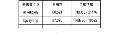
- FIG. Explanatory drawing which illustrates the use fee for every business person stored in use fee DB in Example 3.
- FIG. Explanatory drawing which illustrates the display screen of sales information by a vehicle-mounted display in Example 3.
- FIG. FIG. 14 is a flow chart showing the flow of the operation of the server device in the third embodiment.
- Example 1 This example is an example related to the driving support system 1 using the magnetic marker 10 laid on the road.
- the driving support system 1 is a system that supports the driving of each vehicle 5 by providing support information in consideration of the usage fee collected from each vehicle 5 using the system. The contents will be described with reference to FIGS. 1 to 11.
- the driving support system 1 is configured by a combination of a vehicle 5 connectable to a public communication line such as the Internet 19 and a server device 11 providing support information to the vehicle 5.
- the driving support system 1 is operated on a road on which a magnetic marker 10 integrally holding an RFID (Radio Frequency IDentification) tag 15 (FIG. 2) is laid.
- the driving support system 1 can be connected to an external server (server device) 8 of a financial institution such as a bank or a card company in which an account on the user side or the system side is opened, for example, via the Internet 19.
- the driving support system 1 collects the usage fee by deducting the usage fee from the account of the user and putting it in the account on the system side (payment).
- the magnetic marker 10 is a road marker having a columnar magnet with a diameter of 20 mm and a height of 28 mm, and an RFID tag 15 attached to the end surface thereof.
- the magnetic markers 10 are accommodated, for example, in holes formed at intervals of 10 m along the center of the lanes divided by the left and right lane marks.
- the magnetic marker 10 has a magnetic flux density of 8 ⁇ T (micro Tesla) in the maximum height (250 mm) of the range 100 to 250 mm assumed as the mounting height of the measurement unit 2 (see FIG. 4) on the vehicle 5 side. To work.
- the RFID tag 15 is stacked and disposed on the end face that is upward when laying.
- the RFID tag 15 which is an example of a wireless tag operates by external power feeding by wireless, and externally outputs tag ID (an example of marker specifying information) which is unique identification information by wireless communication.
- the RFID tag 15 is an electronic component in which an IC chip 157 is mounted on the surface of a tag sheet 150 cut out of, for example, PET (Polyethylene terephthalate) film as shown in FIG.
- Printed patterns of the loop coil 151 and the antenna 153 are provided on the surface of the tag sheet 150.
- the loop coil 151 is a power receiving coil in which an exciting current is generated by electromagnetic induction from the outside.
- the antenna 153 is a transmitting antenna for wirelessly transmitting position data and the like.
- the vehicle 5 includes a measurement unit 2, a tag reader 34, a control unit 32, and a communication unit (not shown) having a wireless communication function. Furthermore, the vehicle 5 is provided with a navigation device 6 that performs route guidance to a destination. The vehicle 5 can be wirelessly connected to a public communication line via a communication unit. The vehicle 5 transmits upload information to the server device 11 via the communication unit, and receives provision of support information from the server device 11.
- the measurement unit 2 is, as shown in FIGS. 4 and 5, a unit in which a sensor array 21 for detecting the magnetic marker 10 and an IMU (Inertial Measurement Unit) 22 for realizing inertial navigation are integrated.
- the rod-like measurement unit 2 elongated in the vehicle width direction is attached, for example, to the inside of the front bumper of the vehicle 5 in a state of facing the road surface 100S.
- the mounting height of the measurement unit 2 with respect to the road surface 100S is 200 mm.
- the sensor array 21 included in the measurement unit 2 is a detection processing circuit 212 incorporating 15 magnetic sensors Cn (n is an integer from 1 to 15) arranged in a straight line along the vehicle width direction, and a CPU (not shown) and the like. And have. In the sensor array 21, fifteen magnetic sensors Cn are arranged at equal intervals of 10 cm.
- the magnetic sensor Cn is a sensor that detects magnetism using a known MI effect (Magneto Impedance Effect) in which the impedance of a magnetic sensitive body such as an amorphous wire changes sensitively in response to an external magnetic field.
- MI effect Magnetic Impedance Effect
- magnetic sensing bodies such as amorphous wires are disposed along the orthogonal two-axis direction, thereby making it possible to detect magnetism acting in the orthogonal two-axis direction.
- the magnetic sensor Cn is incorporated in the sensor array 21 so as to detect magnetic components in the traveling direction and the vehicle width direction.
- the magnetic sensor Cn is a high sensitivity sensor having a measurement range of magnetic flux density of ⁇ 0.6 mT and a magnetic flux resolution in the measurement range of 0.02 ⁇ T. In order to cope with high-speed travel of the vehicle 5, each magnetic sensor Cn performs magnetic measurement at a cycle of 3 kHz.
- the magnetic marker 10 can exert magnetism with a magnetic flux density of 8 ⁇ T or more in a range of 100 to 250 mm assumed as the mounting height of the magnetic sensor Cn. If it is the magnetic marker 10 which acts on magnetism with a magnetic flux density of 8 ⁇ T or more, it can be detected with high reliability using the magnetic sensor Cn having a magnetic flux resolution of 0.02 ⁇ T.
- the detection processing circuit 212 (FIG. 5) of the sensor array 21 is an arithmetic circuit that executes marker detection processing and the like for detecting the magnetic marker 10.
- the detection processing circuit 212 is configured using a CPU (central processing unit) that executes various operations, and memory elements such as a ROM (read only memory) and a RAM (random access memory).
- the detection processing circuit 212 acquires sensor signals output from the respective magnetic sensors Cn in a 3 kHz cycle, executes marker detection processing, and inputs the detection result to the control unit 32. Although described in detail later, in this marker detection process, in addition to the detection result of the magnetic marker 10, measurement of the lateral deviation amount of the vehicle 5 with respect to the detected magnetic marker 10 is performed.
- the IMU 22 incorporated in the measurement unit 2 is an inertial navigation unit that estimates the relative position of the vehicle 5 by inertial navigation.
- the IMU 22 includes a two-axis magnetic sensor 221 which is an electronic compass for measuring an azimuth, a two-axis acceleration sensor 222 for measuring an acceleration, and a two-axis gyro sensor 223 for measuring an angular velocity.
- the IMU 22 calculates the relative position to the reference position using the measured acceleration or angular velocity.
- the tag reader 34 included in the vehicle 5 is a communication unit that wirelessly communicates with the RFID tag 15 (FIG. 2) stacked on the end face of the columnar magnetic marker 10.
- the tag reader 34 which is a unit for acquiring a tag ID that is marker specifying information, wirelessly transmits power necessary for the operation of the RFID tag 15 and receives information transmitted by the RFID tag 15.
- the transmission information of the RFID tag 15 includes a tag ID which is identification information (marker specifying information) of the RFID tag 15.
- the tag reader 34 may be integrated into the measurement unit 2.
- the control unit 32 included in the vehicle 5 is a unit for controlling the measurement unit 2 and the tag reader 34 and specifying the position of the vehicle 5, which is the position of the vehicle 5, in real time.
- the control unit 32 includes an electronic substrate (not shown) on which a memory element such as a ROM and a RAM is mounted, in addition to a CPU that executes various calculations.
- control unit 32 specifies the vehicle position is different between when the vehicle 5 reaches the installation site of the magnetic marker 10 and when the vehicle 5 is located between the adjacent magnetic markers 10.
- the control unit 32 specifies the position of the vehicle using support information provided from the server device 11 at the time of detection of the magnetic marker 10.
- the vehicle position is specified based on the relative position of the vehicle 5 estimated by inertial navigation.
- the control unit 32 inputs the position of the vehicle into the navigation device 6 that executes route guidance to the destination, for example.
- the server device 11 includes a main circuit 110 configured by an electronic board (not shown) on which a CPU is mounted, and a storage device (not shown) such as a hard disk is connected to the main circuit 110. Is an arithmetic processing unit.
- the main circuit 110 is provided with a communication function corresponding to a LAN (Local Area Network) not shown.
- the server device 11 can be connected to a public communication line such as the Internet 19 via a communication cable connected to a LAN port (see FIG. 1).
- the server device 11 distributes support information to each upload information acquisition unit (information acquisition unit) 123 that acquires upload information from each vehicle 5 via a public communication line such as the Internet 19 and the like.
- a support information providing unit (information providing unit) 124 is provided.
- the server device 11 includes a usage fee counting unit 122 that counts the usage fee of each vehicle 5 and a payment request unit 121 that transmits a withdrawal request to the external server 8 of the financial institution.
- the marker database (marker DB) 111 is a database in which marker position data (marker position information) representing the installation position of the magnetic marker 10 is stored.
- the usage fee DB 113 is a database in which the usage fee of each vehicle 5 is recorded.
- the account DB 114 is a database that stores account information registered in advance for each vehicle.
- a transmission source management area 118 for registering a vehicle ID which is identification information of the vehicle 5 that is the transmission source of the upload information, is provided in the storage area of the main circuit 110 configured by, for example, a RAM.
- the magnetic sensor Cn can measure the magnetic components in the traveling direction and the vehicle width direction of the vehicle 5. For example, when the magnetic sensor Cn moves in the direction of movement and passes right above the magnetic marker 10, the magnetic measurement value in the direction of movement is inverted in polarity between before and after the magnetic marker 10 as shown in FIG. It changes to cross zero at a position just above ten. Therefore, when the vehicle 5 is traveling, it is determined that the measurement unit 2 is positioned directly above the magnetic marker 10 when the zero crossing Zc whose polarity is reversed is generated for the magnetism in the traveling direction detected by any of the magnetic sensors Cn. it can.
- the detection processing circuit 212 determines that the magnetic marker 10 is detected when the measurement unit 2 is thus positioned directly above the magnetic marker 10 and the zero cross Zc of the magnetic measurement value in the traveling direction is generated.
- the magnetic measurement value in the vehicle width direction changes so that positive and negative are reversed on both sides of the magnetic marker 10 and that it crosses zero at a position immediately above the magnetic marker 10.
- the vehicle width direction detected by the magnetic sensor Cn depending on which side it is on via the magnetic marker 10 The polarity of the magnetism is different.
- the detection processing circuit 212 measures the deviation of the position of the magnetic marker 10 in the vehicle width direction with respect to the center position of the measurement unit 2 (the position of the magnetic sensor C 8) as the lateral deviation amount of the vehicle 5 with respect to the magnetic marker 10.
- the position of the zero crossing Zc is a position corresponding to C9.5 around the middle of C9 and C10.
- the lateral displacement of the vehicle 5 with respect to the magnetic marker 10 is determined based on C8 located at the center of the measurement unit 2 in the vehicle width direction (9.5-8 ) ⁇ 10 cm.
- the tag reader 34 detects the RFID tag 15
- the tag ID reading process for reading the tag ID is executed (S102).
- the tag reader 34 wirelessly transmits power necessary for the operation of the RFID tag 15 to start the operation of the RFID tag 15, and receives transmission data (tag ID and the like) of the RFID tag 15. Then, the tag reader 34 inputs the received tag ID to the control unit 32.
- the control unit 32 generates upload information including a tag ID (S103), associates the vehicle ID which is identification information of the vehicle 5, and transmits it to the server device 11.
- the server apparatus 11 acquires upload information from the vehicle 5 side as shown in FIG. 9 (S201)
- the vehicle ID linked to the upload information is recorded in the transmission source management area 118
- the vehicle 5 of the transmission source of the upload information is registered in the provision destination of the support information (S202).
- the server device 11 grants the vehicle 5 an information acquisition right, which is the right to receive the support information, by registering the provision destination of the support information.
- An information ID which is an identification code of upload information, is linked to the vehicle ID recorded in the transmission source management area 118.
- the server device 11 refers to the marker DB 111 that stores marker position data (marker position information) indicating the installation position of each magnetic marker 10 (S203).
- the server device 11 selectively acquires marker position data of the magnetic marker 10 related to the tag ID included in the upload information from among the marker position data stored in the marker DB 111 (S204).
- the server device 11 generates support information including marker position data acquired from the marker DB 111. Then, the server apparatus 11 transmits the support information to the vehicle 5 that is the transmission source of the upload information acquired in the above-described step S201 and obtains the information acquisition right (S205). Specifically, from the vehicle IDs recorded in the transmission source management area 118 as described above, the vehicle ID to which the information ID of the upload information acquired in the above step S201 is linked is selected, and this vehicle ID is selected. The support information is provided to the vehicle 5 according to the present invention. The vehicle ID recorded in the transmission source management area 118 is deleted as needed in response to the transmission of the support information.
- the server device 11 After transmitting the support information to the vehicle 5 side, the server device 11 adds the charge of the support information to the usage fee managed by the usage fee DB 113 described later for the vehicle 5 of the transmission destination (S206). As a result, the compensation for providing the support information can be obtained from the vehicle 5 as a usage fee.
- the control unit 32 of the vehicle 5 specifies the vehicle position based on the installation position of the magnetic marker 10 represented by the marker position data (S105) ). Specifically, based on the installation position of the magnetic marker 10, the vehicle position is determined by executing an operation of offsetting the lateral shift amount measured by the measurement unit 2 as described above. For example, the navigation device 6 having received the position of the vehicle from the control unit 32 can handle the position of the vehicle as the position of the vehicle and can perform route guidance and the like.
- the control unit 32 uses the vehicle position at the time of detection of the magnetic marker 10 as a reference position to perform inertial navigation.
- the relative position of the vehicle 5 is estimated according to (S112).
- the IMU 22 (FIG. 5) incorporated in the measurement unit 2 integrates the acceleration measured by the two-axis acceleration sensor 222 (FIG. 5) by two-step integration to calculate the displacement amount, and further Calculation is performed to integrate the displacement amount along the traveling direction of the vehicle 5 measured by FIG.
- the control unit 32 estimates the relative position of the vehicle 5 with respect to the reference position described above. Then, the position moved from the reference position by this relative position is specified as the vehicle position (S105).
- the usage charge DB 113 is a database for managing the usage charge to be charged to each user as shown in FIG. In addition, in this example, the user of a vehicle unit is assumed. In the usage fee DB 113, for the vehicle ID of each vehicle 5, a usage fee serving as a price for providing support information is recorded. Further, to each vehicle ID of the usage fee DB 113, bank account information registered in advance in the account DB 114 as a collection destination of the usage fee of each vehicle 5 is associated.
- the server device 11 determines the usage fee of each vehicle 5, for example, every month, and executes a withdrawal request to the external server 8 of the financial institution.
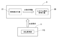
- the withdrawal request includes account information for specifying the account 81 registered for the chargeable vehicle 5, account information for specifying the management account 88 of the depositee managed by the system side, and information such as the fee for use to be collected. ing.
- the account 81 on the vehicle side that deducts the usage fee and the management account 88 on the system side that stores the withdrawn usage fee are accounts of the same financial institution, they are sent to the external server 8 of the financial institution. Depending on the demand for money, money equivalent to the usage fee can be moved between the accounts.
- the vehicle-side account 81 and the system-side management account 88 are accounts of different financial institutions, withdrawal requests are sent to the external servers 8 of both financial institutions, and information between the external servers 8 is obtained. Transfer of money between accounts is realized according to the exchange of
- the driving assistance system 1 of the present example is a system for providing assistance information including marker position data representing the installation position of the magnetic marker 10 to the vehicle 5 that has detected the magnetic marker 10.
- the position of the host vehicle can be specified with high accuracy based on the installation position of the magnetic marker 10. If this driving support system 1 is used, for example, the vehicle position can be accurately grasped even in an environment, equipment or situation where it is not possible to receive radio waves of a GPS (Global Positioning System) satellite.
- GPS Global Positioning System
- the usage fee is totaled for each vehicle 5 that is the user of the support information, and a withdrawal request is transmitted to the financial institution that manages the account of the user.
- the driving support system 1 since it is possible to collect the use fee according to the history of providing the support information, it is possible for the user to bear at least a part of the cost on the system side.
- the user since the usage fee corresponding to the history of providing the support information is collected from the vehicle 5, the user needs at least a part of the cost for laying the magnetic marker 10 and the cost for system operation such as maintenance. Can be collected from the vehicle 5 side. Since the cost on the system side can be covered according to the charge to the vehicle 5 side who is the user, the construction cost such as the installation cost of the magnetic marker 10 is easy, and the installation route of the magnetic marker 10 can be expanded. It is easy. And if the laying line of the magnetic marker 10 increases, the situation where the magnetic marker 10 can not be used can be reduced, so the convenience of the driving support system 1 can be further improved and the collection of the use fee from the vehicle 5 side becomes even easier .
- whether or not the provision of the support information including the marker position data is received may be selectively set by the selection operation or the selection process on the vehicle side. For example, in a city center or a mountainous area where a building stands, the reception state of GPS radio waves is not sufficient, and it may not be possible to properly execute an instruction such as right turn or left turn during route guidance by the navigation device.
- provision of support information including marker position data enables accurate route guidance regardless of the reception state of the GPS radio waves. For example, while traveling in a city center or a mountainous area where a building stands, it is also possible to set a state to receive provision of support information by a driver's selection operation or selection processing by a navigation device.
- the server device 11 integrally including a support information providing unit 124 for providing support information to the vehicle 5 side, a marker DB 111 for storing marker position data representing the installation position of the magnetic marker 10, etc.
- a support information providing unit 124 for providing support information to the vehicle 5 side
- a marker DB 111 for storing marker position data representing the installation position of the magnetic marker 10, etc.
- the plurality of devices may be remotely installed as long as they are communicably connected by a public communication line such as the Internet 19 or a dedicated communication line.
- each vehicle 5 with control information to be provided for automatic driving of the vehicle 5 as the support information.
- control information for example, a steering operation angle and an accelerator opening degree for the vehicle to travel along the road on which the magnetic marker 10 is arranged with respect to the vehicle 5 having transmitted the lateral shift amount to the magnetic marker 10 in the upload information. It is good to provide control information.
- automatic travel of the vehicle 5 along the magnetic marker 10 can be realized by the control information included as service information in the support information.
- the server device 11 side there is an advantage that the vehicle position can be specified with higher accuracy by acquiring the lateral displacement amount. It is good to collect the fee for use of support information including control information from the vehicle 5 side.
- the vehicle 5 may be configured to be able to select whether or not to receive provision of control information by displaying on the in-vehicle display a selection screen indicating whether to use automatic driving. You may want to use automatic driving when you want to drive easily on the way home from vacations.
- the lateral shift amount measured at the time of detection may be included in the upload information.
- detection of unstable travel such as meandering operation or lane departure can be performed on the server device 11 side.
- warning information on unstable driving in the support information and to collect a fee for using the warning information from the vehicle side.
- the vehicle 5 may be configured to be able to select on the in-vehicle display whether or not to receive provision of the alarm information by displaying a selection screen on whether to use the alarm function. If you are tired or sleepy, use the alarm function.
- Example 2 This example is an example in which the configuration is changed based on the driving support system of the first embodiment so as to be able to provide pay congestion information. This content will be described with reference to FIGS. 12 to 14.
- the operation when the driving support system of the present embodiment provides the support information including the traffic jam information will be described according to the flowchart of FIG.
- the flow of the operation will be described starting from a procedure (S301) in which the server apparatus includes traffic information acquired from the outside in support information and provides the support information to the vehicle side.
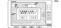
- the control unit on the vehicle side (reference numeral 32 in FIG. 5 referred to in the first embodiment) is in route guidance by the navigation device 6 and If there is a congestion section or the like in the vicinity of the route, congestion information is presented on the display screen of the in-vehicle display 66 as shown in FIG. 13 (S402). Further, the in-vehicle display 66 displays an inquiry screen (FIG. 14) as to whether or not to recalculate the route using the traffic congestion information (S403).
- the control unit transmits a request signal of congestion information data (navigation data) necessary for recalculation of the route to the server device. (S405). After that, the control unit executes route recalculation using navigation data (S302: YES ⁇ S303) transmitted by the server device in response to the request signal (S406). At the vehicle side, route guidance for guiding to the route recalculated by the navigation device 6 is executed (S407).
- the server device transmits the navigation data (S303)
- the server device refers to the usage fee of the transmission destination vehicle recorded in the usage fee DB 113, and adds the traffic congestion information fee (S304).
- traffic information such as a construction section or a regulation section may be included in support information and provided.
- traffic information such as a construction section or a regulation section may be included in support information and provided.
- traffic information may be collected from the administration side managing the road, may be collected from the vehicle side receiving the provision of traffic information, or may be collected from both sides.
- traffic congestion information it is also possible to collect the usage fee when it is used for route calculation.
- the other configurations and operational effects are the same as in the first embodiment.
- Example 3 The present example is an example in which the configuration is changed based on the driving support system of the first embodiment so as to be able to provide support information including sales information on stores, services and the like.
- this driving support system in addition to collecting the usage fee from the vehicle as compensation for providing the marker position data, the usage fee is collected from the business entity as compensation for providing the sales information to the vehicle. This content will be described with reference to FIGS. 15 to 23.
- an attribute database (attribute DB, not shown) capable of storing attribute information of vehicles and drivers in advance is provided in a control unit (corresponding to reference numeral 32 in FIG. 5). ing.
- the control unit sets a transmission information selection screen for setting transmission information included in the upload information among the attribute information. It is possible to display (Fig. 16) and the like on the in-vehicle display 66.
- attribute input screen it is possible to input driver's personal information such as gender, age, hobbies, occupation and the like.
- the attribute information input via these attribute input screens is stored in the attribute DB of the control unit.
- the attribute DB may be provided in the server apparatus.
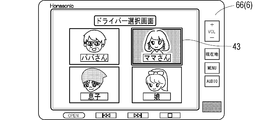
- the driver selection screen (selection operation unit) illustrated in FIG. 15 is an example of a screen that displays, for example, a father, a mother, a son, and a daughter who possess a driver's license among family members constituting a family who owns a vehicle. .
- a father a mother
- a son a daughter
- a driver's license among family members constituting a family who owns a vehicle.
- the mother drives, by touching the inside of the corresponding display frame 43, it is possible to set oneself (mother) as a driver.
- the display screen of the in-vehicle display 66 is switched to the transmission information selection screen of FIG. 16 under the control of the control unit.
- the transmission information selection screen (selection operation unit) illustrated in FIG. 16 is, for example, a selection screen corresponding to the mother who is the driver selected on the driver selection screen (FIG. 15).
- this transmission information selection screen personal information of the driver is displayed in a selectable manner.
- the display frame 44 is switched to hatch display under control of the control unit, and corresponding information is set as transmission information.
- the setting can be canceled by touching the hatched display frame 44 again, and external transmission of the corresponding information can be stopped.
- the server device 11 (FIG. 17) is provided with a town information database (town information DB) 116 that stores business information related to shops, services, and the like.
- the server device 11 can include the sales information stored in the town information DB 116 in the support information and can provide it.
- the usage fee DB 113 of the server device 11 in addition to the usage fee for charging each vehicle, the usage fee for charging each business provider of the business information provider is recorded and managed.
- the main circuit 110 of the server device 11 manages the vehicle ID of the business information provision destination for each provider.
- An area 119 is provided.
- a business or the like who provides goods or services is managed by a business operator ID which is identification information, and information about business etc. is stored separately for each area such as A5. ing.
- the information on a business entity, etc. includes information or data such as name, position (latitude and longitude), business type, target layer assumed as a customer, comment, location (address) and the like.
- Each business operator can selectively set the type of provision of sales information in advance.
- the type of provision of sales information for example, type 1 of providing sales information at random to vehicles located in the range of 500 m around with reference to the location of the business, and a target group providing sales information are limited.
- As a target layer it is possible to set a gender-specific layer such as the F1 layer of a 20-34-year-old female or the M1 layer of a 20-34-year-old male.
- the control unit on the vehicle side adds to the tag ID of the detected magnetic marker, for example, by the transmission information selection screen of FIG.
- the selected transmission information (personal information) is included in the upload information and transmitted.
- the server apparatus 11 When the server apparatus 11 receives the upload information from the vehicle side as shown in FIG. 19 (S501), the server apparatus 11 first records the vehicle ID linked to the upload information in the transmission source management area 118, thereby transmitting the upload information Is registered as a provision destination of support information (S502). The server device 11 grants an information acquisition right, which is a right to receive the support information, to the vehicle by registering the provision destination of the support information. An information ID, which is an identification code of upload information, is linked to the vehicle ID recorded in the transmission source management area 118.
- the server apparatus 11 refers to the marker DB 111 storing marker position data (marker position information) representing the installation position of each magnetic marker (S 503), and is included in the upload information from among the stored marker position data. Marker position data of the magnetic marker related to the tag ID is acquired (S504). Then, the server device 11 generates support information including the marker position data acquired from the marker DB 111 (S505). If personal information is not included in the upload information (S506: NO), this support information is transmitted as it is (S512), and the charge is added to the usage fee of the vehicle as in the first embodiment (S513).
- the server apparatus 11 refers to the town information DB 116 and, for example, a sales office located in the surrounding 500 m range based on the marker position data acquired in step S504. Information is searched (S507).
- the server apparatus 11 sequentially checks the provided type of provision for the retrieved business information (S508).
- the sales information is incorporated into the support information (S509).
- the vehicle IDs of the provision destination vehicles are sequentially recorded in the provision destination management area 119.
- the vehicle ID of the provision destination is registered in the provision destination list (FIG. 20) for each business operator recorded in the provision destination management area 119.
- the vehicle ID is registered with a time limit, and is sequentially deleted according to the passage of a predetermined time such as 10 minutes, for example.
- the server apparatus 11 adds the charge as the provision fee of the sales information to the usage charge imposed on the provider (the provider related to the sales information) of the provider of the sales information incorporated in step S509 (S510).
- the usage fee DB 113 the usage fee is recorded and managed for each enterprise, and the account information stored in the account DB 114 registered in advance for deducting the usage fee of each enterprise is tied to the enterprise ID And managed (see FIG. 21).
- the server apparatus 11 determines that the personal information included in the upload information is the sales information It is determined whether it corresponds to the target layer (see FIG. 18) set in the information (S529). If the personal information corresponds to the target layer (S529: YES), the server apparatus 11 incorporates the sales information into the support information (S509), similar to the flow of processing described in the case of the provision type 1 (S509), and the business operator A charge as an information provision charge is added to the usage charge of (S510). If the personal information does not correspond to the target layer (S529: NO), the processing of step S509 for incorporating the sales information into the support information and step S510 for adding a fee to the usage fee of the business is bypassed.
- the server device 11 repeatedly executes the processing from step S508 to step S510 for each piece of business information searched in step S507 described above (S511: present). Then, after processing for all sales information is finished (S511: no), besides the marker position data, the support information incorporating sales information is transmitted to the vehicle side (S512), and the charge of the support information including the marker position data Is added to the usage fee of the vehicle managed by the usage fee DB 113 as in the first embodiment (S513). At the time of provision of sales information, it is also preferable to make the use fee on the vehicle side free.
- an information display screen illustrated in FIG. 22 can be displayed on the on-vehicle display 66.
- sales information such as a nearby store of the vehicle indicated by the icon 45 is displayed.
- the display screen may be switched to a display screen of information such as the address, the telephone number, and the comment of the corresponding business, or may be displayed in a pop-up.
- the information may be transmitted to the server device 11. With such a configuration, it is possible to charge the business operator with a usage fee as a fee for providing detailed information.
- the vehicle to which the sales information is provided is located at a place where a business person related to the sales information operates a business (place related to sales information)
- a business person related to the sales information operates a business
- the fee as the success reward on the system side is added to the usage fee on the business operator side to enable the collection of the success fee, while the benefit point that can be used to pay the usage fee is used on the vehicle side as a benefit Grant to
- the server apparatus 11 When the server apparatus 11 receives from the vehicle side upload information including a purport that it has parked (S701), it executes a process of estimating a parking position (S702). For example, the installation position of the magnetic marker corresponding to the tag ID included in the upload information received immediately before may be estimated as the parking position.
- the server device 11 refers to the town information DB 116 to search for a business located within a range of, for example, 200 m based on the parking position estimated in step S702 (S703). Then, for example, with reference to the provision destination list illustrated in FIG. 20, a list of vehicle IDs for which sales information has been provided is acquired for each business found in the search (S704). Then, in this vehicle ID, there is no vehicle ID relating to the parked vehicle of the transmission source of the upload information in step S701, that is, whether or not the searched business provider provided the sales information to the parked vehicle (S705).
- the vehicle to which the information is provided is registered in the provision destination list with a time limit of 10 minutes. Therefore, in the determination of step S705, the parked vehicle provides information during the past 10 minutes. It is the judgment of whether or not the vehicle is
- the server apparatus 11 charges the usage fee of the business operator managed by the usage fee DB 113 as a success fee on the system side Are added (S706), thereby enabling the collection of the success fee. Furthermore, a bonus point that can be used to pay the usage fee is granted to the vehicle side using the sales information (S 707, point grant unit). Then, the server apparatus 11 executes the above processing for all the operators searched in step S703 (S708: YES), and when the processing is finished for all the operators (S708: NO), it accompanies parking of the vehicle. End a series of processing.
- the driving support system of the present example it is possible to collect the usage fee as the information provision fee from the business entity that provides the sales information for advertising. Furthermore, when the vehicle side uses the sales information and visits a store (the place related to the sales information) or the like of the sales information provider, the success fee can be collected from the business entity side. On the other hand, on the vehicle side using the sales information, points usable for payment of the usage fee are awarded as a benefit. According to such a privilege, the vehicle side can be motivated to utilize the sales information, so that the use of the sales information on the vehicle side can be promoted and provision of the sales information from the business entity side can be promoted. And if provision and use of sales information become active, it is possible to expand the fee income.
- the sales information is used by the vehicle side It is determined that it has been done and the employer is required to pay a success fee. Instead of this, it is also possible to impose a success fee payment to the business operator when purchasing a product relating to business information or using a service that is a service with money as compensation.
- Services that are services include, for example, haircut of a barber, provision of food and drink at a restaurant, and the like. The other configurations and operational effects are the same as in the first embodiment.
Landscapes
- Engineering & Computer Science (AREA)
- Business, Economics & Management (AREA)
- Physics & Mathematics (AREA)
- General Physics & Mathematics (AREA)
- Accounting & Taxation (AREA)
- Strategic Management (AREA)
- Finance (AREA)
- Radar, Positioning & Navigation (AREA)
- Remote Sensing (AREA)
- Development Economics (AREA)
- Theoretical Computer Science (AREA)
- General Business, Economics & Management (AREA)
- Economics (AREA)
- Computer Networks & Wireless Communication (AREA)
- Marketing (AREA)
- Game Theory and Decision Science (AREA)
- Entrepreneurship & Innovation (AREA)
- Automation & Control Theory (AREA)
- Signal Processing (AREA)
- Human Resources & Organizations (AREA)
- Analytical Chemistry (AREA)
- Chemical & Material Sciences (AREA)
- Computing Systems (AREA)
- Operations Research (AREA)
- Quality & Reliability (AREA)
- Tourism & Hospitality (AREA)
- Traffic Control Systems (AREA)
- Navigation (AREA)
- Management, Administration, Business Operations System, And Electronic Commerce (AREA)
- Financial Or Insurance-Related Operations Such As Payment And Settlement (AREA)
Abstract
La présente invention concerne un système d'aide à la conduite (1) capable de collecter des frais d'utilisation d'un utilisateur à l'aide du système, le système comprenant : une unité d'acquisition d'informations qui acquiert, à partir d'un véhicule (5) capable d'acquérir des informations de spécification de marqueur pour spécifier un marqueur magnétique détecté (10), des informations de téléversement comprenant les informations de spécification de marqueur ; une base de données de marqueur dans laquelle les informations de spécification de marqueur sont connectées et des données de position de marqueur sont enregistrées ; une unité de fourniture d'informations qui fournit des informations d'aide comprenant les données de position de marqueur au véhicule (5); une unité de calcul de frais d'utilisation qui calcule les frais d'utilisation à facturer sur le véhicule (5) en fonction de l'historique des informations d'aide fournies ; et une unité de demande de paiement qui transmet une demande de déboursement à un serveur externe de l'institution financière qui gère le compte à partir duquel les frais d'utilisation doivent être retirés.
Priority Applications (5)
| Application Number | Priority Date | Filing Date | Title |
|---|---|---|---|
| CN201980008072.1A CN111587446B (zh) | 2018-01-16 | 2019-01-11 | 驾驶支援系统 |
| SG11202006705QA SG11202006705QA (en) | 2018-01-16 | 2019-01-11 | Driving support system |
| EP19741870.0A EP3742382A4 (fr) | 2018-01-16 | 2019-01-11 | Système d'aide à la conduite |
| US16/960,918 US11164217B2 (en) | 2018-01-16 | 2019-01-11 | Driving support system |
| US17/460,378 US11631111B2 (en) | 2018-01-16 | 2021-08-30 | Driving support system |
Applications Claiming Priority (2)
| Application Number | Priority Date | Filing Date | Title |
|---|---|---|---|
| JP2018-004794 | 2018-01-16 | ||
| JP2018004794A JP7091668B2 (ja) | 2018-01-16 | 2018-01-16 | 運転支援システム |
Related Child Applications (2)
| Application Number | Title | Priority Date | Filing Date |
|---|---|---|---|
| US16/960,918 A-371-Of-International US11164217B2 (en) | 2018-01-16 | 2019-01-11 | Driving support system |
| US17/460,378 Continuation US11631111B2 (en) | 2018-01-16 | 2021-08-30 | Driving support system |
Publications (1)
| Publication Number | Publication Date |
|---|---|
| WO2019142740A1 true WO2019142740A1 (fr) | 2019-07-25 |
Family
ID=67302413
Family Applications (1)
| Application Number | Title | Priority Date | Filing Date |
|---|---|---|---|
| PCT/JP2019/000718 WO2019142740A1 (fr) | 2018-01-16 | 2019-01-11 | Système d'aide à la conduite |
Country Status (6)
| Country | Link |
|---|---|
| US (2) | US11164217B2 (fr) |
| EP (1) | EP3742382A4 (fr) |
| JP (1) | JP7091668B2 (fr) |
| CN (1) | CN111587446B (fr) |
| SG (1) | SG11202006705QA (fr) |
| WO (1) | WO2019142740A1 (fr) |
Families Citing this family (5)
| Publication number | Priority date | Publication date | Assignee | Title |
|---|---|---|---|---|
| JP6928307B2 (ja) * | 2017-03-28 | 2021-09-01 | 愛知製鋼株式会社 | マーカ検出システム及びマーカ検出方法 |
| JP6920975B2 (ja) * | 2017-12-12 | 2021-08-18 | 愛知製鋼株式会社 | 施工装置、施工方法、及び施工システム |
| JP6965815B2 (ja) * | 2018-04-12 | 2021-11-10 | 愛知製鋼株式会社 | マーカ検出システム、及びマーカ検出システムの運用方法 |
| US11604476B1 (en) | 2018-10-05 | 2023-03-14 | Glydways Inc. | Road-based vehicle guidance system |
| CN113272751A (zh) * | 2018-12-28 | 2021-08-17 | 爱知制钢株式会社 | 磁性标识器系统 |
Citations (6)
| Publication number | Priority date | Publication date | Assignee | Title |
|---|---|---|---|---|
| JP2002333322A (ja) * | 2001-05-07 | 2002-11-22 | Sony Corp | ナビゲーション装置、情報処理装置及びネットワーク配信システム |
| WO2008139889A1 (fr) * | 2007-04-27 | 2008-11-20 | Kabushiki Kaisha Kenwood | Dispositif embarqué et système de distribution d'informations publicitaires |
| JP2013102310A (ja) * | 2011-11-08 | 2013-05-23 | Sumitomo Electric Ind Ltd | 無線通信システム、情報提供装置、移動体端末、及び移動体端末へ情報を提供する方法 |
| JP2015201107A (ja) * | 2014-04-09 | 2015-11-12 | 株式会社豊田中央研究所 | ポイント管理装置、ポイント管理システム、及びプログラム |
| JP2017199247A (ja) | 2016-04-28 | 2017-11-02 | 愛知製鋼株式会社 | 運転支援システム |
| WO2017187881A1 (fr) * | 2016-04-28 | 2017-11-02 | 愛知製鋼株式会社 | Système d'aide à la conduite |
Family Cites Families (18)
| Publication number | Priority date | Publication date | Assignee | Title |
|---|---|---|---|---|
| US9177476B2 (en) * | 1997-10-22 | 2015-11-03 | American Vehicular Sciences Llc | Method and system for guiding a person to a location |
| JP2001343249A (ja) * | 2000-06-01 | 2001-12-14 | Nec Data Terminal Ltd | ドライバ案内システムおよび広告料課金方法 |
| US6728629B2 (en) * | 2000-11-24 | 2004-04-27 | National Institute For Land And Infrastructure Management, Ministry Of Land, Infrastructure And Transport | On-road reference point positional data delivery device |
| JP2002288286A (ja) * | 2001-03-23 | 2002-10-04 | Toshiba Corp | 車両管理システムを利用したビジネス支援システムおよびその支援方法 |
| JP3839678B2 (ja) * | 2001-03-27 | 2006-11-01 | 三菱電機株式会社 | 車両位置認識装置 |
| JP2003288536A (ja) * | 2002-03-28 | 2003-10-10 | Seiko Epson Corp | 地図情報提供システム |
| JP2006330943A (ja) * | 2005-05-24 | 2006-12-07 | Kddi Corp | 成功管理システム、携帯端末装置、ナビゲーション管理システム、ナビゲーションプログラムおよび成功管理方法 |
| JP2008051524A (ja) * | 2006-08-22 | 2008-03-06 | Matsushita Electric Ind Co Ltd | 経路案内システム |
| JP2008242976A (ja) * | 2007-03-28 | 2008-10-09 | Hitachi Kokusai Electric Inc | ナビゲーション装置向け広告配信システム |
| US9488466B2 (en) * | 2009-09-24 | 2016-11-08 | Trimble Navigation Limited | System and method for tracking objects |
| JP5375805B2 (ja) * | 2010-11-26 | 2013-12-25 | トヨタ自動車株式会社 | 運転支援システム及び運転支援管理センター |
| EP2511868B1 (fr) * | 2011-04-15 | 2013-04-10 | Kapsch TrafficCom AG | Procédé de calcul d'utilisations d'espaces |
| US20120290150A1 (en) * | 2011-05-13 | 2012-11-15 | John Doughty | Apparatus, system, and method for providing and using location information |
| EP2752821A2 (fr) * | 2013-01-02 | 2014-07-09 | Albert Kuiper | Amélioration de la mise en oeuvre de la tarification routière |
| US20160086128A1 (en) * | 2014-09-18 | 2016-03-24 | Fetch1 Transport LLC | System and method for on-demand transportation of parcels |
| JP6741436B2 (ja) * | 2016-02-10 | 2020-08-19 | 株式会社ゼンリン | 運転支援システム |
| JP6658230B2 (ja) * | 2016-04-07 | 2020-03-04 | 愛知製鋼株式会社 | 位置捕捉システム |
| CN107045737B (zh) * | 2017-06-21 | 2023-04-28 | 中国工商银行股份有限公司 | 一种高速公路支付系统、方法及车载识别装置 |
-
2018
- 2018-01-16 JP JP2018004794A patent/JP7091668B2/ja active Active
-
2019
- 2019-01-11 EP EP19741870.0A patent/EP3742382A4/fr active Pending
- 2019-01-11 SG SG11202006705QA patent/SG11202006705QA/en unknown
- 2019-01-11 CN CN201980008072.1A patent/CN111587446B/zh active Active
- 2019-01-11 WO PCT/JP2019/000718 patent/WO2019142740A1/fr active Search and Examination
- 2019-01-11 US US16/960,918 patent/US11164217B2/en active Active
-
2021
- 2021-08-30 US US17/460,378 patent/US11631111B2/en active Active
Patent Citations (6)
| Publication number | Priority date | Publication date | Assignee | Title |
|---|---|---|---|---|
| JP2002333322A (ja) * | 2001-05-07 | 2002-11-22 | Sony Corp | ナビゲーション装置、情報処理装置及びネットワーク配信システム |
| WO2008139889A1 (fr) * | 2007-04-27 | 2008-11-20 | Kabushiki Kaisha Kenwood | Dispositif embarqué et système de distribution d'informations publicitaires |
| JP2013102310A (ja) * | 2011-11-08 | 2013-05-23 | Sumitomo Electric Ind Ltd | 無線通信システム、情報提供装置、移動体端末、及び移動体端末へ情報を提供する方法 |
| JP2015201107A (ja) * | 2014-04-09 | 2015-11-12 | 株式会社豊田中央研究所 | ポイント管理装置、ポイント管理システム、及びプログラム |
| JP2017199247A (ja) | 2016-04-28 | 2017-11-02 | 愛知製鋼株式会社 | 運転支援システム |
| WO2017187881A1 (fr) * | 2016-04-28 | 2017-11-02 | 愛知製鋼株式会社 | Système d'aide à la conduite |
Non-Patent Citations (1)
| Title |
|---|
| See also references of EP3742382A4 |
Also Published As
| Publication number | Publication date |
|---|---|
| JP7091668B2 (ja) | 2022-06-28 |
| US11631111B2 (en) | 2023-04-18 |
| EP3742382A4 (fr) | 2021-10-06 |
| US11164217B2 (en) | 2021-11-02 |
| SG11202006705QA (en) | 2020-08-28 |
| JP2019125136A (ja) | 2019-07-25 |
| CN111587446A (zh) | 2020-08-25 |
| EP3742382A1 (fr) | 2020-11-25 |
| US20210390588A1 (en) | 2021-12-16 |
| US20200357027A1 (en) | 2020-11-12 |
| CN111587446B (zh) | 2024-04-12 |
Similar Documents
| Publication | Publication Date | Title |
|---|---|---|
| WO2019142740A1 (fr) | Système d'aide à la conduite | |
| CN111602029B (zh) | 车辆位置管理系统及车辆位置管理方法 | |
| EP2806412B1 (fr) | Calcul d'itinéraire pour système de navigation utilisant des données échangées avec des machines de vente de billet | |
| US7834778B2 (en) | Parking space locator | |
| TWI426233B (zh) | Parking lot space navigation device | |
| US20180247534A1 (en) | Integrated system for monitoring parking lot conditions | |
| US20210221359A1 (en) | Automatic parking system | |
| KR20150065127A (ko) | 스마트폰 앱을 이용한 주차장 안내 시스템 및 방법 | |
| WO2009098813A1 (fr) | Système de paiement de prix de billet d'autobus routier | |
| JP7209052B2 (ja) | 施設管理装置、施設管理方法、プログラム、及び施設管理システム | |
| JP2015076079A (ja) | 利用目的推定システム、端末装置、利用目的推定方法、およびプログラム | |
| JP4432862B2 (ja) | 車載ナビゲーション装置 | |
| JP3956908B2 (ja) | 車両用情報案内装置 | |
| JP2016045732A (ja) | 情報処理装置、情報処理方法およびプログラム | |
| JP6344770B2 (ja) | 電子装置、課金表示プログラムおよび課金表示方法 | |
| JP2009025885A (ja) | タクシー運賃カード決済システム | |
| JP2008292417A (ja) | ナビゲーション装置 | |
| JP2022125075A (ja) | 情報生成装置、情報生成方法及び情報処理装置 | |
| JP2018163679A (ja) | 利用目的推定システム、端末装置、利用目的推定方法、およびプログラム | |
| JP2002022477A (ja) | 誘導案内システム | |
| JP2017125810A (ja) | ナビゲーション装置及びコンピュータプログラム | |
| JP2014159979A (ja) | 交通情報処理装置及びその処理方法とプログラム | |
| KR20090059210A (ko) | 통행료 결제 방법 및 이를 이용한 네비게이션 및 시스템 |
Legal Events
| Date | Code | Title | Description |
|---|---|---|---|
| 121 | Ep: the epo has been informed by wipo that ep was designated in this application |
Ref document number: 19741870 Country of ref document: EP Kind code of ref document: A1 |
|
| DPE1 | Request for preliminary examination filed after expiration of 19th month from priority date (pct application filed from 20040101) | ||
| NENP | Non-entry into the national phase |
Ref country code: DE |
|
| ENP | Entry into the national phase |
Ref document number: 2019741870 Country of ref document: EP Effective date: 20200817 |