WO2019142740A1 - Driving assistance system - Google Patents
Driving assistance system Download PDFInfo
- Publication number
- WO2019142740A1 WO2019142740A1 PCT/JP2019/000718 JP2019000718W WO2019142740A1 WO 2019142740 A1 WO2019142740 A1 WO 2019142740A1 JP 2019000718 W JP2019000718 W JP 2019000718W WO 2019142740 A1 WO2019142740 A1 WO 2019142740A1
- Authority
- WO
- WIPO (PCT)
- Prior art keywords
- information
- vehicle
- marker
- usage fee
- magnetic
- Prior art date
Links
Images


Classifications
-
- G—PHYSICS
- G01—MEASURING; TESTING
- G01C—MEASURING DISTANCES, LEVELS OR BEARINGS; SURVEYING; NAVIGATION; GYROSCOPIC INSTRUMENTS; PHOTOGRAMMETRY OR VIDEOGRAMMETRY
- G01C21/00—Navigation; Navigational instruments not provided for in groups G01C1/00 - G01C19/00
- G01C21/26—Navigation; Navigational instruments not provided for in groups G01C1/00 - G01C19/00 specially adapted for navigation in a road network
- G01C21/28—Navigation; Navigational instruments not provided for in groups G01C1/00 - G01C19/00 specially adapted for navigation in a road network with correlation of data from several navigational instruments
-
- G—PHYSICS
- G06—COMPUTING; CALCULATING OR COUNTING
- G06Q—INFORMATION AND COMMUNICATION TECHNOLOGY [ICT] SPECIALLY ADAPTED FOR ADMINISTRATIVE, COMMERCIAL, FINANCIAL, MANAGERIAL OR SUPERVISORY PURPOSES; SYSTEMS OR METHODS SPECIALLY ADAPTED FOR ADMINISTRATIVE, COMMERCIAL, FINANCIAL, MANAGERIAL OR SUPERVISORY PURPOSES, NOT OTHERWISE PROVIDED FOR
- G06Q30/00—Commerce
- G06Q30/02—Marketing; Price estimation or determination; Fundraising
- G06Q30/0241—Advertisements
- G06Q30/0273—Determination of fees for advertising
-
- G—PHYSICS
- G01—MEASURING; TESTING
- G01C—MEASURING DISTANCES, LEVELS OR BEARINGS; SURVEYING; NAVIGATION; GYROSCOPIC INSTRUMENTS; PHOTOGRAMMETRY OR VIDEOGRAMMETRY
- G01C21/00—Navigation; Navigational instruments not provided for in groups G01C1/00 - G01C19/00
- G01C21/26—Navigation; Navigational instruments not provided for in groups G01C1/00 - G01C19/00 specially adapted for navigation in a road network
- G01C21/34—Route searching; Route guidance
- G01C21/3407—Route searching; Route guidance specially adapted for specific applications
- G01C21/3415—Dynamic re-routing, e.g. recalculating the route when the user deviates from calculated route or after detecting real-time traffic data or accidents
-
- G—PHYSICS
- G01—MEASURING; TESTING
- G01C—MEASURING DISTANCES, LEVELS OR BEARINGS; SURVEYING; NAVIGATION; GYROSCOPIC INSTRUMENTS; PHOTOGRAMMETRY OR VIDEOGRAMMETRY
- G01C21/00—Navigation; Navigational instruments not provided for in groups G01C1/00 - G01C19/00
- G01C21/26—Navigation; Navigational instruments not provided for in groups G01C1/00 - G01C19/00 specially adapted for navigation in a road network
- G01C21/34—Route searching; Route guidance
- G01C21/3453—Special cost functions, i.e. other than distance or default speed limit of road segments
- G01C21/3492—Special cost functions, i.e. other than distance or default speed limit of road segments employing speed data or traffic data, e.g. real-time or historical
-
- G—PHYSICS
- G01—MEASURING; TESTING
- G01C—MEASURING DISTANCES, LEVELS OR BEARINGS; SURVEYING; NAVIGATION; GYROSCOPIC INSTRUMENTS; PHOTOGRAMMETRY OR VIDEOGRAMMETRY
- G01C21/00—Navigation; Navigational instruments not provided for in groups G01C1/00 - G01C19/00
- G01C21/26—Navigation; Navigational instruments not provided for in groups G01C1/00 - G01C19/00 specially adapted for navigation in a road network
- G01C21/34—Route searching; Route guidance
- G01C21/36—Input/output arrangements for on-board computers
- G01C21/3697—Output of additional, non-guidance related information, e.g. low fuel level
-
- G—PHYSICS
- G06—COMPUTING; CALCULATING OR COUNTING
- G06Q—INFORMATION AND COMMUNICATION TECHNOLOGY [ICT] SPECIALLY ADAPTED FOR ADMINISTRATIVE, COMMERCIAL, FINANCIAL, MANAGERIAL OR SUPERVISORY PURPOSES; SYSTEMS OR METHODS SPECIALLY ADAPTED FOR ADMINISTRATIVE, COMMERCIAL, FINANCIAL, MANAGERIAL OR SUPERVISORY PURPOSES, NOT OTHERWISE PROVIDED FOR
- G06Q10/00—Administration; Management
- G06Q10/04—Forecasting or optimisation specially adapted for administrative or management purposes, e.g. linear programming or "cutting stock problem"
- G06Q10/047—Optimisation of routes or paths, e.g. travelling salesman problem
-
- G—PHYSICS
- G06—COMPUTING; CALCULATING OR COUNTING
- G06Q—INFORMATION AND COMMUNICATION TECHNOLOGY [ICT] SPECIALLY ADAPTED FOR ADMINISTRATIVE, COMMERCIAL, FINANCIAL, MANAGERIAL OR SUPERVISORY PURPOSES; SYSTEMS OR METHODS SPECIALLY ADAPTED FOR ADMINISTRATIVE, COMMERCIAL, FINANCIAL, MANAGERIAL OR SUPERVISORY PURPOSES, NOT OTHERWISE PROVIDED FOR
- G06Q20/00—Payment architectures, schemes or protocols
- G06Q20/08—Payment architectures
- G06Q20/085—Payment architectures involving remote charge determination or related payment systems
- G06Q20/0855—Payment architectures involving remote charge determination or related payment systems involving a third party
-
- G—PHYSICS
- G06—COMPUTING; CALCULATING OR COUNTING
- G06Q—INFORMATION AND COMMUNICATION TECHNOLOGY [ICT] SPECIALLY ADAPTED FOR ADMINISTRATIVE, COMMERCIAL, FINANCIAL, MANAGERIAL OR SUPERVISORY PURPOSES; SYSTEMS OR METHODS SPECIALLY ADAPTED FOR ADMINISTRATIVE, COMMERCIAL, FINANCIAL, MANAGERIAL OR SUPERVISORY PURPOSES, NOT OTHERWISE PROVIDED FOR
- G06Q20/00—Payment architectures, schemes or protocols
- G06Q20/08—Payment architectures
- G06Q20/10—Payment architectures specially adapted for electronic funds transfer [EFT] systems; specially adapted for home banking systems
- G06Q20/102—Bill distribution or payments
-
- G—PHYSICS
- G06—COMPUTING; CALCULATING OR COUNTING
- G06Q—INFORMATION AND COMMUNICATION TECHNOLOGY [ICT] SPECIALLY ADAPTED FOR ADMINISTRATIVE, COMMERCIAL, FINANCIAL, MANAGERIAL OR SUPERVISORY PURPOSES; SYSTEMS OR METHODS SPECIALLY ADAPTED FOR ADMINISTRATIVE, COMMERCIAL, FINANCIAL, MANAGERIAL OR SUPERVISORY PURPOSES, NOT OTHERWISE PROVIDED FOR
- G06Q20/00—Payment architectures, schemes or protocols
- G06Q20/08—Payment architectures
- G06Q20/14—Payment architectures specially adapted for billing systems
- G06Q20/145—Payments according to the detected use or quantity
-
- G—PHYSICS
- G06—COMPUTING; CALCULATING OR COUNTING
- G06Q—INFORMATION AND COMMUNICATION TECHNOLOGY [ICT] SPECIALLY ADAPTED FOR ADMINISTRATIVE, COMMERCIAL, FINANCIAL, MANAGERIAL OR SUPERVISORY PURPOSES; SYSTEMS OR METHODS SPECIALLY ADAPTED FOR ADMINISTRATIVE, COMMERCIAL, FINANCIAL, MANAGERIAL OR SUPERVISORY PURPOSES, NOT OTHERWISE PROVIDED FOR
- G06Q20/00—Payment architectures, schemes or protocols
- G06Q20/30—Payment architectures, schemes or protocols characterised by the use of specific devices or networks
- G06Q20/308—Payment architectures, schemes or protocols characterised by the use of specific devices or networks using the Internet of Things
-
- G—PHYSICS
- G06—COMPUTING; CALCULATING OR COUNTING
- G06Q—INFORMATION AND COMMUNICATION TECHNOLOGY [ICT] SPECIALLY ADAPTED FOR ADMINISTRATIVE, COMMERCIAL, FINANCIAL, MANAGERIAL OR SUPERVISORY PURPOSES; SYSTEMS OR METHODS SPECIALLY ADAPTED FOR ADMINISTRATIVE, COMMERCIAL, FINANCIAL, MANAGERIAL OR SUPERVISORY PURPOSES, NOT OTHERWISE PROVIDED FOR
- G06Q20/00—Payment architectures, schemes or protocols
- G06Q20/30—Payment architectures, schemes or protocols characterised by the use of specific devices or networks
- G06Q20/32—Payment architectures, schemes or protocols characterised by the use of specific devices or networks using wireless devices
- G06Q20/322—Aspects of commerce using mobile devices [M-devices]
-
- G—PHYSICS
- G06—COMPUTING; CALCULATING OR COUNTING
- G06Q—INFORMATION AND COMMUNICATION TECHNOLOGY [ICT] SPECIALLY ADAPTED FOR ADMINISTRATIVE, COMMERCIAL, FINANCIAL, MANAGERIAL OR SUPERVISORY PURPOSES; SYSTEMS OR METHODS SPECIALLY ADAPTED FOR ADMINISTRATIVE, COMMERCIAL, FINANCIAL, MANAGERIAL OR SUPERVISORY PURPOSES, NOT OTHERWISE PROVIDED FOR
- G06Q30/00—Commerce
- G06Q30/02—Marketing; Price estimation or determination; Fundraising
- G06Q30/0207—Discounts or incentives, e.g. coupons or rebates
-
- G—PHYSICS
- G06—COMPUTING; CALCULATING OR COUNTING
- G06Q—INFORMATION AND COMMUNICATION TECHNOLOGY [ICT] SPECIALLY ADAPTED FOR ADMINISTRATIVE, COMMERCIAL, FINANCIAL, MANAGERIAL OR SUPERVISORY PURPOSES; SYSTEMS OR METHODS SPECIALLY ADAPTED FOR ADMINISTRATIVE, COMMERCIAL, FINANCIAL, MANAGERIAL OR SUPERVISORY PURPOSES, NOT OTHERWISE PROVIDED FOR
- G06Q30/00—Commerce
- G06Q30/02—Marketing; Price estimation or determination; Fundraising
- G06Q30/0241—Advertisements
- G06Q30/0251—Targeted advertisements
- G06Q30/0265—Vehicular advertisement
- G06Q30/0266—Vehicular advertisement based on the position of the vehicle
-
- G—PHYSICS
- G07—CHECKING-DEVICES
- G07C—TIME OR ATTENDANCE REGISTERS; REGISTERING OR INDICATING THE WORKING OF MACHINES; GENERATING RANDOM NUMBERS; VOTING OR LOTTERY APPARATUS; ARRANGEMENTS, SYSTEMS OR APPARATUS FOR CHECKING NOT PROVIDED FOR ELSEWHERE
- G07C5/00—Registering or indicating the working of vehicles
- G07C5/008—Registering or indicating the working of vehicles communicating information to a remotely located station
-
- G—PHYSICS
- G08—SIGNALLING
- G08G—TRAFFIC CONTROL SYSTEMS
- G08G1/00—Traffic control systems for road vehicles
- G08G1/01—Detecting movement of traffic to be counted or controlled
- G08G1/0104—Measuring and analyzing of parameters relative to traffic conditions
- G08G1/0108—Measuring and analyzing of parameters relative to traffic conditions based on the source of data
- G08G1/0116—Measuring and analyzing of parameters relative to traffic conditions based on the source of data from roadside infrastructure, e.g. beacons
-
- G—PHYSICS
- G08—SIGNALLING
- G08G—TRAFFIC CONTROL SYSTEMS
- G08G1/00—Traffic control systems for road vehicles
- G08G1/01—Detecting movement of traffic to be counted or controlled
- G08G1/017—Detecting movement of traffic to be counted or controlled identifying vehicles
-
- G—PHYSICS
- G08—SIGNALLING
- G08G—TRAFFIC CONTROL SYSTEMS
- G08G1/00—Traffic control systems for road vehicles
- G08G1/01—Detecting movement of traffic to be counted or controlled
- G08G1/02—Detecting movement of traffic to be counted or controlled using treadles built into the road
-
- G—PHYSICS
- G08—SIGNALLING
- G08G—TRAFFIC CONTROL SYSTEMS
- G08G1/00—Traffic control systems for road vehicles
- G08G1/01—Detecting movement of traffic to be counted or controlled
- G08G1/042—Detecting movement of traffic to be counted or controlled using inductive or magnetic detectors
-
- H—ELECTRICITY
- H04—ELECTRIC COMMUNICATION TECHNIQUE
- H04W—WIRELESS COMMUNICATION NETWORKS
- H04W4/00—Services specially adapted for wireless communication networks; Facilities therefor
- H04W4/02—Services making use of location information
- H04W4/029—Location-based management or tracking services
-
- H—ELECTRICITY
- H04—ELECTRIC COMMUNICATION TECHNIQUE
- H04W—WIRELESS COMMUNICATION NETWORKS
- H04W4/00—Services specially adapted for wireless communication networks; Facilities therefor
- H04W4/30—Services specially adapted for particular environments, situations or purposes
- H04W4/40—Services specially adapted for particular environments, situations or purposes for vehicles, e.g. vehicle-to-pedestrians [V2P]
-
- G—PHYSICS
- G06—COMPUTING; CALCULATING OR COUNTING
- G06Q—INFORMATION AND COMMUNICATION TECHNOLOGY [ICT] SPECIALLY ADAPTED FOR ADMINISTRATIVE, COMMERCIAL, FINANCIAL, MANAGERIAL OR SUPERVISORY PURPOSES; SYSTEMS OR METHODS SPECIALLY ADAPTED FOR ADMINISTRATIVE, COMMERCIAL, FINANCIAL, MANAGERIAL OR SUPERVISORY PURPOSES, NOT OTHERWISE PROVIDED FOR
- G06Q2240/00—Transportation facility access, e.g. fares, tolls or parking
Definitions
- the present invention relates to a driving support system using magnetic markers laid on a road.
- Patent Document 1 proposes a magnetic marker system for providing information to the vehicle side using a combination of magnetic marker laying modes.
- the conventional magnetic marker system has the following problems. That is, burdens such as the cost for laying the magnetic marker on the road and the operation cost such as maintenance are obstacles to the spread of the system using the magnetic marker.
- the present invention has been made in view of the above-mentioned conventional problems, and an object of the present invention is to provide a driving support system capable of collecting a usage fee from the side using the system.
- the present invention is an information acquisition unit for detecting uploading information including marker specifying information from a vehicle side capable of detecting a magnetic marker laid on a road and acquiring marker specifying information for specifying the detected magnetic marker , A marker database in which marker position information representing a laying position of a magnetic marker is recorded by linking the marker specific information; An information providing unit for providing support information including marker position information associated with marker specifying information included in the upload information to a vehicle side of a transmission source of the upload information; A usage charge counting unit that counts usage charges imposed on the vehicle according to the history of providing the support information; An account database in which account information of an account for debiting the usage fee and a management account on the system side for storing the withdrawn usage fee are registered as information of a financial institution account accessible from the public communication line; Payment for sending a withdrawal request to an external server device of a financial institution that manages an account for debiting the usage fee in order to move the amount corresponding to the usage fee collected by the usage fee aggregation unit to the management account on the system side And a
- the driving support system of the present invention counts the usage charges imposed on the side receiving the provision of the support information, and transmits a withdrawal request to a financial institution that manages an account for debiting the usage charges. According to this driving support system, since it is possible to collect the use fee according to the history of providing the support information, it is possible to make the vehicle side bear at least a part of the cost on the system side. As described above, according to the driving support system of the present invention, it is possible to collect the use fee from the side that uses the support information.
- FIG. 1 is a block diagram showing a configuration of a vehicle side in Embodiment 1.
- FIG. 2 is a block diagram showing the configuration of a server apparatus in the first embodiment.
- FIG. 7 is an explanatory view exemplifying a change of a magnetic measurement value in a traveling direction when passing a magnetic marker in the first embodiment;
- FIG. 7 is an explanatory view exemplifying a distribution of magnetic measurement values in the vehicle width direction by the magnetic sensors Cn arranged in the vehicle width direction in the first embodiment;
- FIG. 2 is a flow chart showing the flow of the operation of the driving support system in the first embodiment.
- Explanatory drawing which illustrates the utilization charge of each vehicle recorded on utilization charge DB in Example 1.
- FIG. 6 is an explanatory diagram of a charging process in the first embodiment.
- FIG. 7 is a flow chart showing the operation flow of the driving support system in the second embodiment.
- Explanatory drawing which illustrates the presentation screen of traffic congestion information in Example 2.
- FIG. Explanatory drawing which illustrates the utilization inquiry screen of traffic congestion information in Example 2.
- FIG. 14 is an explanatory view exemplifying a driver selection screen in the third embodiment.
- FIG. 14 is an explanatory view exemplifying a transmission information selection screen in the third embodiment;
- FIG. 14 is a block diagram showing the configuration of a server apparatus in Embodiment 3.
- Explanatory drawing which illustrates the sales information stored in town information DB in Example 3.
- FIG. 14 is a flow chart showing the flow of the operation of the server device in the third embodiment.
- Explanatory drawing which illustrates the provision destination list of sales information in Example 3.
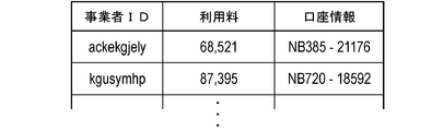
- FIG. Explanatory drawing which illustrates the use fee for every business person stored in use fee DB in Example 3.
- FIG. Explanatory drawing which illustrates the display screen of sales information by a vehicle-mounted display in Example 3.
- FIG. FIG. 14 is a flow chart showing the flow of the operation of the server device in the third embodiment.
- Example 1 This example is an example related to the driving support system 1 using the magnetic marker 10 laid on the road.
- the driving support system 1 is a system that supports the driving of each vehicle 5 by providing support information in consideration of the usage fee collected from each vehicle 5 using the system. The contents will be described with reference to FIGS. 1 to 11.
- the driving support system 1 is configured by a combination of a vehicle 5 connectable to a public communication line such as the Internet 19 and a server device 11 providing support information to the vehicle 5.
- the driving support system 1 is operated on a road on which a magnetic marker 10 integrally holding an RFID (Radio Frequency IDentification) tag 15 (FIG. 2) is laid.
- the driving support system 1 can be connected to an external server (server device) 8 of a financial institution such as a bank or a card company in which an account on the user side or the system side is opened, for example, via the Internet 19.
- the driving support system 1 collects the usage fee by deducting the usage fee from the account of the user and putting it in the account on the system side (payment).
- the magnetic marker 10 is a road marker having a columnar magnet with a diameter of 20 mm and a height of 28 mm, and an RFID tag 15 attached to the end surface thereof.
- the magnetic markers 10 are accommodated, for example, in holes formed at intervals of 10 m along the center of the lanes divided by the left and right lane marks.
- the magnetic marker 10 has a magnetic flux density of 8 ⁇ T (micro Tesla) in the maximum height (250 mm) of the range 100 to 250 mm assumed as the mounting height of the measurement unit 2 (see FIG. 4) on the vehicle 5 side. To work.
- the RFID tag 15 is stacked and disposed on the end face that is upward when laying.
- the RFID tag 15 which is an example of a wireless tag operates by external power feeding by wireless, and externally outputs tag ID (an example of marker specifying information) which is unique identification information by wireless communication.
- the RFID tag 15 is an electronic component in which an IC chip 157 is mounted on the surface of a tag sheet 150 cut out of, for example, PET (Polyethylene terephthalate) film as shown in FIG.
- Printed patterns of the loop coil 151 and the antenna 153 are provided on the surface of the tag sheet 150.
- the loop coil 151 is a power receiving coil in which an exciting current is generated by electromagnetic induction from the outside.
- the antenna 153 is a transmitting antenna for wirelessly transmitting position data and the like.
- the vehicle 5 includes a measurement unit 2, a tag reader 34, a control unit 32, and a communication unit (not shown) having a wireless communication function. Furthermore, the vehicle 5 is provided with a navigation device 6 that performs route guidance to a destination. The vehicle 5 can be wirelessly connected to a public communication line via a communication unit. The vehicle 5 transmits upload information to the server device 11 via the communication unit, and receives provision of support information from the server device 11.
- the measurement unit 2 is, as shown in FIGS. 4 and 5, a unit in which a sensor array 21 for detecting the magnetic marker 10 and an IMU (Inertial Measurement Unit) 22 for realizing inertial navigation are integrated.
- the rod-like measurement unit 2 elongated in the vehicle width direction is attached, for example, to the inside of the front bumper of the vehicle 5 in a state of facing the road surface 100S.
- the mounting height of the measurement unit 2 with respect to the road surface 100S is 200 mm.
- the sensor array 21 included in the measurement unit 2 is a detection processing circuit 212 incorporating 15 magnetic sensors Cn (n is an integer from 1 to 15) arranged in a straight line along the vehicle width direction, and a CPU (not shown) and the like. And have. In the sensor array 21, fifteen magnetic sensors Cn are arranged at equal intervals of 10 cm.
- the magnetic sensor Cn is a sensor that detects magnetism using a known MI effect (Magneto Impedance Effect) in which the impedance of a magnetic sensitive body such as an amorphous wire changes sensitively in response to an external magnetic field.
- MI effect Magnetic Impedance Effect
- magnetic sensing bodies such as amorphous wires are disposed along the orthogonal two-axis direction, thereby making it possible to detect magnetism acting in the orthogonal two-axis direction.
- the magnetic sensor Cn is incorporated in the sensor array 21 so as to detect magnetic components in the traveling direction and the vehicle width direction.
- the magnetic sensor Cn is a high sensitivity sensor having a measurement range of magnetic flux density of ⁇ 0.6 mT and a magnetic flux resolution in the measurement range of 0.02 ⁇ T. In order to cope with high-speed travel of the vehicle 5, each magnetic sensor Cn performs magnetic measurement at a cycle of 3 kHz.
- the magnetic marker 10 can exert magnetism with a magnetic flux density of 8 ⁇ T or more in a range of 100 to 250 mm assumed as the mounting height of the magnetic sensor Cn. If it is the magnetic marker 10 which acts on magnetism with a magnetic flux density of 8 ⁇ T or more, it can be detected with high reliability using the magnetic sensor Cn having a magnetic flux resolution of 0.02 ⁇ T.
- the detection processing circuit 212 (FIG. 5) of the sensor array 21 is an arithmetic circuit that executes marker detection processing and the like for detecting the magnetic marker 10.
- the detection processing circuit 212 is configured using a CPU (central processing unit) that executes various operations, and memory elements such as a ROM (read only memory) and a RAM (random access memory).
- the detection processing circuit 212 acquires sensor signals output from the respective magnetic sensors Cn in a 3 kHz cycle, executes marker detection processing, and inputs the detection result to the control unit 32. Although described in detail later, in this marker detection process, in addition to the detection result of the magnetic marker 10, measurement of the lateral deviation amount of the vehicle 5 with respect to the detected magnetic marker 10 is performed.
- the IMU 22 incorporated in the measurement unit 2 is an inertial navigation unit that estimates the relative position of the vehicle 5 by inertial navigation.
- the IMU 22 includes a two-axis magnetic sensor 221 which is an electronic compass for measuring an azimuth, a two-axis acceleration sensor 222 for measuring an acceleration, and a two-axis gyro sensor 223 for measuring an angular velocity.
- the IMU 22 calculates the relative position to the reference position using the measured acceleration or angular velocity.
- the tag reader 34 included in the vehicle 5 is a communication unit that wirelessly communicates with the RFID tag 15 (FIG. 2) stacked on the end face of the columnar magnetic marker 10.
- the tag reader 34 which is a unit for acquiring a tag ID that is marker specifying information, wirelessly transmits power necessary for the operation of the RFID tag 15 and receives information transmitted by the RFID tag 15.
- the transmission information of the RFID tag 15 includes a tag ID which is identification information (marker specifying information) of the RFID tag 15.
- the tag reader 34 may be integrated into the measurement unit 2.
- the control unit 32 included in the vehicle 5 is a unit for controlling the measurement unit 2 and the tag reader 34 and specifying the position of the vehicle 5, which is the position of the vehicle 5, in real time.
- the control unit 32 includes an electronic substrate (not shown) on which a memory element such as a ROM and a RAM is mounted, in addition to a CPU that executes various calculations.
- control unit 32 specifies the vehicle position is different between when the vehicle 5 reaches the installation site of the magnetic marker 10 and when the vehicle 5 is located between the adjacent magnetic markers 10.
- the control unit 32 specifies the position of the vehicle using support information provided from the server device 11 at the time of detection of the magnetic marker 10.
- the vehicle position is specified based on the relative position of the vehicle 5 estimated by inertial navigation.
- the control unit 32 inputs the position of the vehicle into the navigation device 6 that executes route guidance to the destination, for example.
- the server device 11 includes a main circuit 110 configured by an electronic board (not shown) on which a CPU is mounted, and a storage device (not shown) such as a hard disk is connected to the main circuit 110. Is an arithmetic processing unit.
- the main circuit 110 is provided with a communication function corresponding to a LAN (Local Area Network) not shown.
- the server device 11 can be connected to a public communication line such as the Internet 19 via a communication cable connected to a LAN port (see FIG. 1).
- the server device 11 distributes support information to each upload information acquisition unit (information acquisition unit) 123 that acquires upload information from each vehicle 5 via a public communication line such as the Internet 19 and the like.
- a support information providing unit (information providing unit) 124 is provided.
- the server device 11 includes a usage fee counting unit 122 that counts the usage fee of each vehicle 5 and a payment request unit 121 that transmits a withdrawal request to the external server 8 of the financial institution.
- the marker database (marker DB) 111 is a database in which marker position data (marker position information) representing the installation position of the magnetic marker 10 is stored.
- the usage fee DB 113 is a database in which the usage fee of each vehicle 5 is recorded.
- the account DB 114 is a database that stores account information registered in advance for each vehicle.
- a transmission source management area 118 for registering a vehicle ID which is identification information of the vehicle 5 that is the transmission source of the upload information, is provided in the storage area of the main circuit 110 configured by, for example, a RAM.
- the magnetic sensor Cn can measure the magnetic components in the traveling direction and the vehicle width direction of the vehicle 5. For example, when the magnetic sensor Cn moves in the direction of movement and passes right above the magnetic marker 10, the magnetic measurement value in the direction of movement is inverted in polarity between before and after the magnetic marker 10 as shown in FIG. It changes to cross zero at a position just above ten. Therefore, when the vehicle 5 is traveling, it is determined that the measurement unit 2 is positioned directly above the magnetic marker 10 when the zero crossing Zc whose polarity is reversed is generated for the magnetism in the traveling direction detected by any of the magnetic sensors Cn. it can.
- the detection processing circuit 212 determines that the magnetic marker 10 is detected when the measurement unit 2 is thus positioned directly above the magnetic marker 10 and the zero cross Zc of the magnetic measurement value in the traveling direction is generated.
- the magnetic measurement value in the vehicle width direction changes so that positive and negative are reversed on both sides of the magnetic marker 10 and that it crosses zero at a position immediately above the magnetic marker 10.
- the vehicle width direction detected by the magnetic sensor Cn depending on which side it is on via the magnetic marker 10 The polarity of the magnetism is different.
- the detection processing circuit 212 measures the deviation of the position of the magnetic marker 10 in the vehicle width direction with respect to the center position of the measurement unit 2 (the position of the magnetic sensor C 8) as the lateral deviation amount of the vehicle 5 with respect to the magnetic marker 10.
- the position of the zero crossing Zc is a position corresponding to C9.5 around the middle of C9 and C10.
- the lateral displacement of the vehicle 5 with respect to the magnetic marker 10 is determined based on C8 located at the center of the measurement unit 2 in the vehicle width direction (9.5-8 ) ⁇ 10 cm.
- the tag reader 34 detects the RFID tag 15
- the tag ID reading process for reading the tag ID is executed (S102).
- the tag reader 34 wirelessly transmits power necessary for the operation of the RFID tag 15 to start the operation of the RFID tag 15, and receives transmission data (tag ID and the like) of the RFID tag 15. Then, the tag reader 34 inputs the received tag ID to the control unit 32.
- the control unit 32 generates upload information including a tag ID (S103), associates the vehicle ID which is identification information of the vehicle 5, and transmits it to the server device 11.
- the server apparatus 11 acquires upload information from the vehicle 5 side as shown in FIG. 9 (S201)
- the vehicle ID linked to the upload information is recorded in the transmission source management area 118
- the vehicle 5 of the transmission source of the upload information is registered in the provision destination of the support information (S202).
- the server device 11 grants the vehicle 5 an information acquisition right, which is the right to receive the support information, by registering the provision destination of the support information.
- An information ID which is an identification code of upload information, is linked to the vehicle ID recorded in the transmission source management area 118.
- the server device 11 refers to the marker DB 111 that stores marker position data (marker position information) indicating the installation position of each magnetic marker 10 (S203).
- the server device 11 selectively acquires marker position data of the magnetic marker 10 related to the tag ID included in the upload information from among the marker position data stored in the marker DB 111 (S204).
- the server device 11 generates support information including marker position data acquired from the marker DB 111. Then, the server apparatus 11 transmits the support information to the vehicle 5 that is the transmission source of the upload information acquired in the above-described step S201 and obtains the information acquisition right (S205). Specifically, from the vehicle IDs recorded in the transmission source management area 118 as described above, the vehicle ID to which the information ID of the upload information acquired in the above step S201 is linked is selected, and this vehicle ID is selected. The support information is provided to the vehicle 5 according to the present invention. The vehicle ID recorded in the transmission source management area 118 is deleted as needed in response to the transmission of the support information.
- the server device 11 After transmitting the support information to the vehicle 5 side, the server device 11 adds the charge of the support information to the usage fee managed by the usage fee DB 113 described later for the vehicle 5 of the transmission destination (S206). As a result, the compensation for providing the support information can be obtained from the vehicle 5 as a usage fee.
- the control unit 32 of the vehicle 5 specifies the vehicle position based on the installation position of the magnetic marker 10 represented by the marker position data (S105) ). Specifically, based on the installation position of the magnetic marker 10, the vehicle position is determined by executing an operation of offsetting the lateral shift amount measured by the measurement unit 2 as described above. For example, the navigation device 6 having received the position of the vehicle from the control unit 32 can handle the position of the vehicle as the position of the vehicle and can perform route guidance and the like.
- the control unit 32 uses the vehicle position at the time of detection of the magnetic marker 10 as a reference position to perform inertial navigation.
- the relative position of the vehicle 5 is estimated according to (S112).
- the IMU 22 (FIG. 5) incorporated in the measurement unit 2 integrates the acceleration measured by the two-axis acceleration sensor 222 (FIG. 5) by two-step integration to calculate the displacement amount, and further Calculation is performed to integrate the displacement amount along the traveling direction of the vehicle 5 measured by FIG.
- the control unit 32 estimates the relative position of the vehicle 5 with respect to the reference position described above. Then, the position moved from the reference position by this relative position is specified as the vehicle position (S105).
- the usage charge DB 113 is a database for managing the usage charge to be charged to each user as shown in FIG. In addition, in this example, the user of a vehicle unit is assumed. In the usage fee DB 113, for the vehicle ID of each vehicle 5, a usage fee serving as a price for providing support information is recorded. Further, to each vehicle ID of the usage fee DB 113, bank account information registered in advance in the account DB 114 as a collection destination of the usage fee of each vehicle 5 is associated.
- the server device 11 determines the usage fee of each vehicle 5, for example, every month, and executes a withdrawal request to the external server 8 of the financial institution.
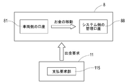
- the withdrawal request includes account information for specifying the account 81 registered for the chargeable vehicle 5, account information for specifying the management account 88 of the depositee managed by the system side, and information such as the fee for use to be collected. ing.
- the account 81 on the vehicle side that deducts the usage fee and the management account 88 on the system side that stores the withdrawn usage fee are accounts of the same financial institution, they are sent to the external server 8 of the financial institution. Depending on the demand for money, money equivalent to the usage fee can be moved between the accounts.
- the vehicle-side account 81 and the system-side management account 88 are accounts of different financial institutions, withdrawal requests are sent to the external servers 8 of both financial institutions, and information between the external servers 8 is obtained. Transfer of money between accounts is realized according to the exchange of
- the driving assistance system 1 of the present example is a system for providing assistance information including marker position data representing the installation position of the magnetic marker 10 to the vehicle 5 that has detected the magnetic marker 10.
- the position of the host vehicle can be specified with high accuracy based on the installation position of the magnetic marker 10. If this driving support system 1 is used, for example, the vehicle position can be accurately grasped even in an environment, equipment or situation where it is not possible to receive radio waves of a GPS (Global Positioning System) satellite.
- GPS Global Positioning System
- the usage fee is totaled for each vehicle 5 that is the user of the support information, and a withdrawal request is transmitted to the financial institution that manages the account of the user.
- the driving support system 1 since it is possible to collect the use fee according to the history of providing the support information, it is possible for the user to bear at least a part of the cost on the system side.
- the user since the usage fee corresponding to the history of providing the support information is collected from the vehicle 5, the user needs at least a part of the cost for laying the magnetic marker 10 and the cost for system operation such as maintenance. Can be collected from the vehicle 5 side. Since the cost on the system side can be covered according to the charge to the vehicle 5 side who is the user, the construction cost such as the installation cost of the magnetic marker 10 is easy, and the installation route of the magnetic marker 10 can be expanded. It is easy. And if the laying line of the magnetic marker 10 increases, the situation where the magnetic marker 10 can not be used can be reduced, so the convenience of the driving support system 1 can be further improved and the collection of the use fee from the vehicle 5 side becomes even easier .
- whether or not the provision of the support information including the marker position data is received may be selectively set by the selection operation or the selection process on the vehicle side. For example, in a city center or a mountainous area where a building stands, the reception state of GPS radio waves is not sufficient, and it may not be possible to properly execute an instruction such as right turn or left turn during route guidance by the navigation device.
- provision of support information including marker position data enables accurate route guidance regardless of the reception state of the GPS radio waves. For example, while traveling in a city center or a mountainous area where a building stands, it is also possible to set a state to receive provision of support information by a driver's selection operation or selection processing by a navigation device.
- the server device 11 integrally including a support information providing unit 124 for providing support information to the vehicle 5 side, a marker DB 111 for storing marker position data representing the installation position of the magnetic marker 10, etc.
- a support information providing unit 124 for providing support information to the vehicle 5 side
- a marker DB 111 for storing marker position data representing the installation position of the magnetic marker 10, etc.
- the plurality of devices may be remotely installed as long as they are communicably connected by a public communication line such as the Internet 19 or a dedicated communication line.
- each vehicle 5 with control information to be provided for automatic driving of the vehicle 5 as the support information.
- control information for example, a steering operation angle and an accelerator opening degree for the vehicle to travel along the road on which the magnetic marker 10 is arranged with respect to the vehicle 5 having transmitted the lateral shift amount to the magnetic marker 10 in the upload information. It is good to provide control information.
- automatic travel of the vehicle 5 along the magnetic marker 10 can be realized by the control information included as service information in the support information.
- the server device 11 side there is an advantage that the vehicle position can be specified with higher accuracy by acquiring the lateral displacement amount. It is good to collect the fee for use of support information including control information from the vehicle 5 side.
- the vehicle 5 may be configured to be able to select whether or not to receive provision of control information by displaying on the in-vehicle display a selection screen indicating whether to use automatic driving. You may want to use automatic driving when you want to drive easily on the way home from vacations.
- the lateral shift amount measured at the time of detection may be included in the upload information.
- detection of unstable travel such as meandering operation or lane departure can be performed on the server device 11 side.
- warning information on unstable driving in the support information and to collect a fee for using the warning information from the vehicle side.
- the vehicle 5 may be configured to be able to select on the in-vehicle display whether or not to receive provision of the alarm information by displaying a selection screen on whether to use the alarm function. If you are tired or sleepy, use the alarm function.
- Example 2 This example is an example in which the configuration is changed based on the driving support system of the first embodiment so as to be able to provide pay congestion information. This content will be described with reference to FIGS. 12 to 14.
- the operation when the driving support system of the present embodiment provides the support information including the traffic jam information will be described according to the flowchart of FIG.
- the flow of the operation will be described starting from a procedure (S301) in which the server apparatus includes traffic information acquired from the outside in support information and provides the support information to the vehicle side.
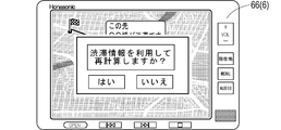
- the control unit on the vehicle side (reference numeral 32 in FIG. 5 referred to in the first embodiment) is in route guidance by the navigation device 6 and If there is a congestion section or the like in the vicinity of the route, congestion information is presented on the display screen of the in-vehicle display 66 as shown in FIG. 13 (S402). Further, the in-vehicle display 66 displays an inquiry screen (FIG. 14) as to whether or not to recalculate the route using the traffic congestion information (S403).
- the control unit transmits a request signal of congestion information data (navigation data) necessary for recalculation of the route to the server device. (S405). After that, the control unit executes route recalculation using navigation data (S302: YES ⁇ S303) transmitted by the server device in response to the request signal (S406). At the vehicle side, route guidance for guiding to the route recalculated by the navigation device 6 is executed (S407).
- the server device transmits the navigation data (S303)
- the server device refers to the usage fee of the transmission destination vehicle recorded in the usage fee DB 113, and adds the traffic congestion information fee (S304).
- traffic information such as a construction section or a regulation section may be included in support information and provided.
- traffic information such as a construction section or a regulation section may be included in support information and provided.
- traffic information may be collected from the administration side managing the road, may be collected from the vehicle side receiving the provision of traffic information, or may be collected from both sides.
- traffic congestion information it is also possible to collect the usage fee when it is used for route calculation.
- the other configurations and operational effects are the same as in the first embodiment.
- Example 3 The present example is an example in which the configuration is changed based on the driving support system of the first embodiment so as to be able to provide support information including sales information on stores, services and the like.
- this driving support system in addition to collecting the usage fee from the vehicle as compensation for providing the marker position data, the usage fee is collected from the business entity as compensation for providing the sales information to the vehicle. This content will be described with reference to FIGS. 15 to 23.
- an attribute database (attribute DB, not shown) capable of storing attribute information of vehicles and drivers in advance is provided in a control unit (corresponding to reference numeral 32 in FIG. 5). ing.
- the control unit sets a transmission information selection screen for setting transmission information included in the upload information among the attribute information. It is possible to display (Fig. 16) and the like on the in-vehicle display 66.
- attribute input screen it is possible to input driver's personal information such as gender, age, hobbies, occupation and the like.
- the attribute information input via these attribute input screens is stored in the attribute DB of the control unit.
- the attribute DB may be provided in the server apparatus.
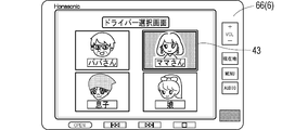
- the driver selection screen (selection operation unit) illustrated in FIG. 15 is an example of a screen that displays, for example, a father, a mother, a son, and a daughter who possess a driver's license among family members constituting a family who owns a vehicle. .
- a father a mother
- a son a daughter
- a driver's license among family members constituting a family who owns a vehicle.
- the mother drives, by touching the inside of the corresponding display frame 43, it is possible to set oneself (mother) as a driver.
- the display screen of the in-vehicle display 66 is switched to the transmission information selection screen of FIG. 16 under the control of the control unit.
- the transmission information selection screen (selection operation unit) illustrated in FIG. 16 is, for example, a selection screen corresponding to the mother who is the driver selected on the driver selection screen (FIG. 15).
- this transmission information selection screen personal information of the driver is displayed in a selectable manner.
- the display frame 44 is switched to hatch display under control of the control unit, and corresponding information is set as transmission information.
- the setting can be canceled by touching the hatched display frame 44 again, and external transmission of the corresponding information can be stopped.
- the server device 11 (FIG. 17) is provided with a town information database (town information DB) 116 that stores business information related to shops, services, and the like.
- the server device 11 can include the sales information stored in the town information DB 116 in the support information and can provide it.
- the usage fee DB 113 of the server device 11 in addition to the usage fee for charging each vehicle, the usage fee for charging each business provider of the business information provider is recorded and managed.
- the main circuit 110 of the server device 11 manages the vehicle ID of the business information provision destination for each provider.
- An area 119 is provided.
- a business or the like who provides goods or services is managed by a business operator ID which is identification information, and information about business etc. is stored separately for each area such as A5. ing.
- the information on a business entity, etc. includes information or data such as name, position (latitude and longitude), business type, target layer assumed as a customer, comment, location (address) and the like.
- Each business operator can selectively set the type of provision of sales information in advance.
- the type of provision of sales information for example, type 1 of providing sales information at random to vehicles located in the range of 500 m around with reference to the location of the business, and a target group providing sales information are limited.
- As a target layer it is possible to set a gender-specific layer such as the F1 layer of a 20-34-year-old female or the M1 layer of a 20-34-year-old male.
- the control unit on the vehicle side adds to the tag ID of the detected magnetic marker, for example, by the transmission information selection screen of FIG.
- the selected transmission information (personal information) is included in the upload information and transmitted.
- the server apparatus 11 When the server apparatus 11 receives the upload information from the vehicle side as shown in FIG. 19 (S501), the server apparatus 11 first records the vehicle ID linked to the upload information in the transmission source management area 118, thereby transmitting the upload information Is registered as a provision destination of support information (S502). The server device 11 grants an information acquisition right, which is a right to receive the support information, to the vehicle by registering the provision destination of the support information. An information ID, which is an identification code of upload information, is linked to the vehicle ID recorded in the transmission source management area 118.
- the server apparatus 11 refers to the marker DB 111 storing marker position data (marker position information) representing the installation position of each magnetic marker (S 503), and is included in the upload information from among the stored marker position data. Marker position data of the magnetic marker related to the tag ID is acquired (S504). Then, the server device 11 generates support information including the marker position data acquired from the marker DB 111 (S505). If personal information is not included in the upload information (S506: NO), this support information is transmitted as it is (S512), and the charge is added to the usage fee of the vehicle as in the first embodiment (S513).
- the server apparatus 11 refers to the town information DB 116 and, for example, a sales office located in the surrounding 500 m range based on the marker position data acquired in step S504. Information is searched (S507).
- the server apparatus 11 sequentially checks the provided type of provision for the retrieved business information (S508).
- the sales information is incorporated into the support information (S509).
- the vehicle IDs of the provision destination vehicles are sequentially recorded in the provision destination management area 119.
- the vehicle ID of the provision destination is registered in the provision destination list (FIG. 20) for each business operator recorded in the provision destination management area 119.
- the vehicle ID is registered with a time limit, and is sequentially deleted according to the passage of a predetermined time such as 10 minutes, for example.
- the server apparatus 11 adds the charge as the provision fee of the sales information to the usage charge imposed on the provider (the provider related to the sales information) of the provider of the sales information incorporated in step S509 (S510).
- the usage fee DB 113 the usage fee is recorded and managed for each enterprise, and the account information stored in the account DB 114 registered in advance for deducting the usage fee of each enterprise is tied to the enterprise ID And managed (see FIG. 21).
- the server apparatus 11 determines that the personal information included in the upload information is the sales information It is determined whether it corresponds to the target layer (see FIG. 18) set in the information (S529). If the personal information corresponds to the target layer (S529: YES), the server apparatus 11 incorporates the sales information into the support information (S509), similar to the flow of processing described in the case of the provision type 1 (S509), and the business operator A charge as an information provision charge is added to the usage charge of (S510). If the personal information does not correspond to the target layer (S529: NO), the processing of step S509 for incorporating the sales information into the support information and step S510 for adding a fee to the usage fee of the business is bypassed.
- the server device 11 repeatedly executes the processing from step S508 to step S510 for each piece of business information searched in step S507 described above (S511: present). Then, after processing for all sales information is finished (S511: no), besides the marker position data, the support information incorporating sales information is transmitted to the vehicle side (S512), and the charge of the support information including the marker position data Is added to the usage fee of the vehicle managed by the usage fee DB 113 as in the first embodiment (S513). At the time of provision of sales information, it is also preferable to make the use fee on the vehicle side free.
- an information display screen illustrated in FIG. 22 can be displayed on the on-vehicle display 66.
- sales information such as a nearby store of the vehicle indicated by the icon 45 is displayed.
- the display screen may be switched to a display screen of information such as the address, the telephone number, and the comment of the corresponding business, or may be displayed in a pop-up.
- the information may be transmitted to the server device 11. With such a configuration, it is possible to charge the business operator with a usage fee as a fee for providing detailed information.
- the vehicle to which the sales information is provided is located at a place where a business person related to the sales information operates a business (place related to sales information)
- a business person related to the sales information operates a business
- the fee as the success reward on the system side is added to the usage fee on the business operator side to enable the collection of the success fee, while the benefit point that can be used to pay the usage fee is used on the vehicle side as a benefit Grant to
- the server apparatus 11 When the server apparatus 11 receives from the vehicle side upload information including a purport that it has parked (S701), it executes a process of estimating a parking position (S702). For example, the installation position of the magnetic marker corresponding to the tag ID included in the upload information received immediately before may be estimated as the parking position.
- the server device 11 refers to the town information DB 116 to search for a business located within a range of, for example, 200 m based on the parking position estimated in step S702 (S703). Then, for example, with reference to the provision destination list illustrated in FIG. 20, a list of vehicle IDs for which sales information has been provided is acquired for each business found in the search (S704). Then, in this vehicle ID, there is no vehicle ID relating to the parked vehicle of the transmission source of the upload information in step S701, that is, whether or not the searched business provider provided the sales information to the parked vehicle (S705).
- the vehicle to which the information is provided is registered in the provision destination list with a time limit of 10 minutes. Therefore, in the determination of step S705, the parked vehicle provides information during the past 10 minutes. It is the judgment of whether or not the vehicle is
- the server apparatus 11 charges the usage fee of the business operator managed by the usage fee DB 113 as a success fee on the system side Are added (S706), thereby enabling the collection of the success fee. Furthermore, a bonus point that can be used to pay the usage fee is granted to the vehicle side using the sales information (S 707, point grant unit). Then, the server apparatus 11 executes the above processing for all the operators searched in step S703 (S708: YES), and when the processing is finished for all the operators (S708: NO), it accompanies parking of the vehicle. End a series of processing.
- the driving support system of the present example it is possible to collect the usage fee as the information provision fee from the business entity that provides the sales information for advertising. Furthermore, when the vehicle side uses the sales information and visits a store (the place related to the sales information) or the like of the sales information provider, the success fee can be collected from the business entity side. On the other hand, on the vehicle side using the sales information, points usable for payment of the usage fee are awarded as a benefit. According to such a privilege, the vehicle side can be motivated to utilize the sales information, so that the use of the sales information on the vehicle side can be promoted and provision of the sales information from the business entity side can be promoted. And if provision and use of sales information become active, it is possible to expand the fee income.
- the sales information is used by the vehicle side It is determined that it has been done and the employer is required to pay a success fee. Instead of this, it is also possible to impose a success fee payment to the business operator when purchasing a product relating to business information or using a service that is a service with money as compensation.
- Services that are services include, for example, haircut of a barber, provision of food and drink at a restaurant, and the like. The other configurations and operational effects are the same as in the first embodiment.
Abstract
A driving assistance system (1) capable of collecting a usage fee from a user using the system, wherein the system comprises: an information acquisition unit that acquires, from a vehicle (5) capable of acquiring marker specification information for specifying a detected magnetic marker (10), upload information including the marker specification information; a marker database in which the marker specification information is connected and marker position data is recorded; an information provision unit that provides assistance information including the marker position data to the vehicle (5); a usage fee calculation unit that calculates the usage fee to be charged to the vehicle (5) in accordance with the history of the assistance information provided; and a payment request unit that transmits a disbursement request to an external server of the financial institution that manages the account from which the usage fee is to be withdrawn.
Description
本発明は、道路に敷設された磁気マーカを利用する運転支援システムに関する。
The present invention relates to a driving support system using magnetic markers laid on a road.
従来より、道路に敷設された磁気マーカを利用する運転支援システムが知られている。例えば、下記の特許文献1では、磁気マーカの敷設態様の組合せを利用して車両側に情報を提供するための磁気マーカのシステムが提案されている。
Conventionally, a driving support system using a magnetic marker laid on a road is known. For example, Patent Document 1 below proposes a magnetic marker system for providing information to the vehicle side using a combination of magnetic marker laying modes.
しかしながら、前記従来の磁気マーカのシステムでは、次のような問題がある。すなわち、磁気マーカを道路に敷設するためのコストやメンテナンス等の運用コスト等の負担が、磁気マーカを利用するシステムを普及させる上での阻害要因となっている。
However, the conventional magnetic marker system has the following problems. That is, burdens such as the cost for laying the magnetic marker on the road and the operation cost such as maintenance are obstacles to the spread of the system using the magnetic marker.
本発明は、前記従来の問題点に鑑みてなされたものであり、システムを利用する側から利用料を徴収可能な運転支援システムを提供しようとするものである。
The present invention has been made in view of the above-mentioned conventional problems, and an object of the present invention is to provide a driving support system capable of collecting a usage fee from the side using the system.
本発明は、道路に敷設された磁気マーカを検出すると共に検出した磁気マーカを特定するためのマーカ特定情報を取得可能な車両側から、該マーカ特定情報を含むアップロード情報を取得する情報取得部と、
前記マーカ特定情報をひも付けて、磁気マーカの敷設位置を表すマーカ位置情報が記録されたマーカデータベースと、
前記アップロード情報に含まれるマーカ特定情報がひも付けられたマーカ位置情報を含む支援情報を該アップロード情報の送信元の車両側に提供する情報提供部と、
前記支援情報を提供した履歴に応じて車両側に課す利用料を集計する利用料集計部と、
公衆通信回線からアクセス可能な金融機関の口座の情報として、利用料を引き落とす口座、及び引き落とした利用料を収めるシステム側の管理口座、の口座情報が登録された口座データベースと、
前記利用料集計部が集計した利用料に相当する金額をシステム側の管理口座に移動させるために、利用料を引き落とす口座を管理する金融機関の外部サーバ装置に対して出金要求を送信する支払要求部と、を備える運転支援システムにある。 The present invention is an information acquisition unit for detecting uploading information including marker specifying information from a vehicle side capable of detecting a magnetic marker laid on a road and acquiring marker specifying information for specifying the detected magnetic marker ,
A marker database in which marker position information representing a laying position of a magnetic marker is recorded by linking the marker specific information;
An information providing unit for providing support information including marker position information associated with marker specifying information included in the upload information to a vehicle side of a transmission source of the upload information;
A usage charge counting unit that counts usage charges imposed on the vehicle according to the history of providing the support information;
An account database in which account information of an account for debiting the usage fee and a management account on the system side for storing the withdrawn usage fee are registered as information of a financial institution account accessible from the public communication line;
Payment for sending a withdrawal request to an external server device of a financial institution that manages an account for debiting the usage fee in order to move the amount corresponding to the usage fee collected by the usage fee aggregation unit to the management account on the system side And a request unit.
本発明の運転支援システムは、支援情報の提供を受ける側に課す利用料を集計し、利用料を引き落とす口座を管理する金融機関に対して出金要求を送信する。この運転支援システムによれば、支援情報を提供した履歴に応じた利用料を徴収できるため、システム側のコストの少なくとも一部を車両側に負担させることが可能になっている。
このように本発明の運転支援システムによれば、支援情報を利用する側から利用料を徴収可能である。 The driving support system of the present invention counts the usage charges imposed on the side receiving the provision of the support information, and transmits a withdrawal request to a financial institution that manages an account for debiting the usage charges. According to this driving support system, since it is possible to collect the use fee according to the history of providing the support information, it is possible to make the vehicle side bear at least a part of the cost on the system side.
As described above, according to the driving support system of the present invention, it is possible to collect the use fee from the side that uses the support information.
本発明の実施の形態につき、以下の実施例を用いて具体的に説明する。
(実施例1)
本例は、道路に敷設された磁気マーカ10を利用する運転支援システム1に関する例である。この運転支援システム1は、システムを利用する各車両5から徴収する利用料を対価として支援情報を提供することで、各車両5の運転を支援するシステムである。この内容について、図1~図11を参照して説明する。 Embodiments of the present invention will be specifically described using the following examples.
Example 1
This example is an example related to thedriving support system 1 using the magnetic marker 10 laid on the road. The driving support system 1 is a system that supports the driving of each vehicle 5 by providing support information in consideration of the usage fee collected from each vehicle 5 using the system. The contents will be described with reference to FIGS. 1 to 11.
(実施例1)
本例は、道路に敷設された磁気マーカ10を利用する運転支援システム1に関する例である。この運転支援システム1は、システムを利用する各車両5から徴収する利用料を対価として支援情報を提供することで、各車両5の運転を支援するシステムである。この内容について、図1~図11を参照して説明する。 Embodiments of the present invention will be specifically described using the following examples.
Example 1
This example is an example related to the
運転支援システム1は、図1のごとく、インターネット19などの公衆通信回線に接続可能な車両5と、車両5に支援情報を提供するサーバ装置11と、の組み合わせにより構成されている。この運転支援システム1は、RFID(Radio Frequency IDentification)タグ15(図2)を一体的に保持する磁気マーカ10が敷設された道路を対象として運用される。運転支援システム1は、利用者やシステム側の口座が開設された銀行やカード会社などの金融機関の外部サーバ(サーバ装置)8と、例えばインターネット19を介して接続可能である。運転支援システム1は、利用者の口座から利用料を引き落としてシステム側の口座に収める(入金)ことにより利用料を徴収する。
As shown in FIG. 1, the driving support system 1 is configured by a combination of a vehicle 5 connectable to a public communication line such as the Internet 19 and a server device 11 providing support information to the vehicle 5. The driving support system 1 is operated on a road on which a magnetic marker 10 integrally holding an RFID (Radio Frequency IDentification) tag 15 (FIG. 2) is laid. The driving support system 1 can be connected to an external server (server device) 8 of a financial institution such as a bank or a card company in which an account on the user side or the system side is opened, for example, via the Internet 19. The driving support system 1 collects the usage fee by deducting the usage fee from the account of the user and putting it in the account on the system side (payment).
以下、(1)磁気マーカ10を概説した後、運転支援システム1を構成する(2)車両5、及び(3)サーバ装置11について説明し、続いて(4)運転支援システム1の動作を説明する。
Hereinafter, after (1) magnetic marker 10 is outlined, (2) vehicles 5 and (3) server device 11 which constitute driving support system 1 are explained, and then (4) operation of driving support system 1 is explained. Do.
(1)磁気マーカ
磁気マーカ10は、図2のごとく、直径20mm、高さ28mmの柱状の磁石により構成され、その端面にRFIDタグ15が貼り付けられた道路マーカである。磁気マーカ10は、例えば、左右のレーンマークで区分された車線の中央に沿って10m間隔で穿設された孔に収容される。 (1) Magnetic Marker As shown in FIG. 2, themagnetic marker 10 is a road marker having a columnar magnet with a diameter of 20 mm and a height of 28 mm, and an RFID tag 15 attached to the end surface thereof. The magnetic markers 10 are accommodated, for example, in holes formed at intervals of 10 m along the center of the lanes divided by the left and right lane marks.
磁気マーカ10は、図2のごとく、直径20mm、高さ28mmの柱状の磁石により構成され、その端面にRFIDタグ15が貼り付けられた道路マーカである。磁気マーカ10は、例えば、左右のレーンマークで区分された車線の中央に沿って10m間隔で穿設された孔に収容される。 (1) Magnetic Marker As shown in FIG. 2, the
磁気マーカ10をなす磁石は、磁性材料である酸化鉄の磁粉を基材である高分子材料中に分散させたフェライトプラスチックマグネットであり、最大エネルギー積(BHmax)=6.4kJ/m3という特性を備えている。この磁気マーカ10は、車両5側の計測ユニット2(図4参照。)の取付け高さとして想定される範囲100~250mmの最大高さ(250mm)において、8μT(マイクロテスラ)の磁束密度の磁気を作用する。
The magnet forming the magnetic marker 10 is a ferrite plastic magnet in which magnetic powder of iron oxide which is a magnetic material is dispersed in a polymer material which is a base material, and has a characteristic of maximum energy product (BHmax) = 6.4 kJ / m 3 Is equipped. The magnetic marker 10 has a magnetic flux density of 8 μT (micro Tesla) in the maximum height (250 mm) of the range 100 to 250 mm assumed as the mounting height of the measurement unit 2 (see FIG. 4) on the vehicle 5 side. To work.
磁気マーカ10では、図2のごとく、敷設時に上向きとなる端面にRFIDタグ15が積層配置されている。無線タグの一例であるRFIDタグ15は、無線による外部給電により動作し、固有の識別情報であるタグID(マーカ特定情報の一例)を無線通信により外部出力する。
In the magnetic marker 10, as shown in FIG. 2, the RFID tag 15 is stacked and disposed on the end face that is upward when laying. The RFID tag 15 which is an example of a wireless tag operates by external power feeding by wireless, and externally outputs tag ID (an example of marker specifying information) which is unique identification information by wireless communication.
RFIDタグ15は、図3のごとく、例えばPET(Polyethylene terephthalate)フィルムから切り出したタグシート150の表面にICチップ157を実装した電子部品である。タグシート150の表面には、ループコイル151及びアンテナ153の印刷パターンが設けられている。ループコイル151は、外部からの電磁誘導によって励磁電流が発生する受電コイルである。アンテナ153は、位置データ等を無線送信するための送信アンテナである。
The RFID tag 15 is an electronic component in which an IC chip 157 is mounted on the surface of a tag sheet 150 cut out of, for example, PET (Polyethylene terephthalate) film as shown in FIG. Printed patterns of the loop coil 151 and the antenna 153 are provided on the surface of the tag sheet 150. The loop coil 151 is a power receiving coil in which an exciting current is generated by electromagnetic induction from the outside. The antenna 153 is a transmitting antenna for wirelessly transmitting position data and the like.
(2)車両
車両5は、図4のごとく、計測ユニット2、タグリーダ34、制御ユニット32、及び無線通信機能を備える通信ユニット(図示略)を備えている。さらに、車両5は、目的地までの経路案内を実行するナビゲーション装置6を備えている。車両5は、通信ユニットを介して公衆通信回線への無線による接続が可能である。車両5は、通信ユニットを介してサーバ装置11に対してアップロード情報を送信し、サーバ装置11から支援情報の提供を受ける。 (2) Vehicle As shown in FIG. 4, thevehicle 5 includes a measurement unit 2, a tag reader 34, a control unit 32, and a communication unit (not shown) having a wireless communication function. Furthermore, the vehicle 5 is provided with a navigation device 6 that performs route guidance to a destination. The vehicle 5 can be wirelessly connected to a public communication line via a communication unit. The vehicle 5 transmits upload information to the server device 11 via the communication unit, and receives provision of support information from the server device 11.
車両5は、図4のごとく、計測ユニット2、タグリーダ34、制御ユニット32、及び無線通信機能を備える通信ユニット(図示略)を備えている。さらに、車両5は、目的地までの経路案内を実行するナビゲーション装置6を備えている。車両5は、通信ユニットを介して公衆通信回線への無線による接続が可能である。車両5は、通信ユニットを介してサーバ装置11に対してアップロード情報を送信し、サーバ装置11から支援情報の提供を受ける。 (2) Vehicle As shown in FIG. 4, the
計測ユニット2は、図4及び図5のごとく、磁気マーカ10を検出するセンサアレイ21と、慣性航法を実現するためのIMU(Inertial Measurement Unit)22と、が一体化されたユニットである。車幅方向に長い棒状をなす計測ユニット2は、例えば車両5のフロントバンパーの内側などに路面100Sと対面する状態で取り付けられる。本例の車両5の場合、路面100Sを基準とした計測ユニット2の取付け高さが200mmとなっている。
The measurement unit 2 is, as shown in FIGS. 4 and 5, a unit in which a sensor array 21 for detecting the magnetic marker 10 and an IMU (Inertial Measurement Unit) 22 for realizing inertial navigation are integrated. The rod-like measurement unit 2 elongated in the vehicle width direction is attached, for example, to the inside of the front bumper of the vehicle 5 in a state of facing the road surface 100S. In the case of the vehicle 5 of this example, the mounting height of the measurement unit 2 with respect to the road surface 100S is 200 mm.
計測ユニット2が備えるセンサアレイ21は、車幅方向に沿って一直線上に配列された15個の磁気センサCn(nは1~15の整数)と、図示しないCPU等を内蔵した検出処理回路212と、を備えている。このセンサアレイ21では、15個の磁気センサCnが10cmの等間隔で配置されている。
The sensor array 21 included in the measurement unit 2 is a detection processing circuit 212 incorporating 15 magnetic sensors Cn (n is an integer from 1 to 15) arranged in a straight line along the vehicle width direction, and a CPU (not shown) and the like. And have. In the sensor array 21, fifteen magnetic sensors Cn are arranged at equal intervals of 10 cm.
磁気センサCnは、アモルファスワイヤなどの感磁体のインピーダンスが外部磁界に応じて敏感に変化するという公知のMI効果(Magneto Impedance Effect)を利用して磁気を検出するセンサである。磁気センサCnでは、アモルファスワイヤなどの図示しない感磁体が直交する2軸方向に沿って配置され、これにより直交する2軸方向に作用する磁気の検出が可能となっている。なお、本例では、進行方向及び車幅方向の磁気成分を検出できるように磁気センサCnがセンサアレイ21に組み込まれている。
The magnetic sensor Cn is a sensor that detects magnetism using a known MI effect (Magneto Impedance Effect) in which the impedance of a magnetic sensitive body such as an amorphous wire changes sensitively in response to an external magnetic field. In the magnetic sensor Cn, magnetic sensing bodies (not shown) such as amorphous wires are disposed along the orthogonal two-axis direction, thereby making it possible to detect magnetism acting in the orthogonal two-axis direction. In the present embodiment, the magnetic sensor Cn is incorporated in the sensor array 21 so as to detect magnetic components in the traveling direction and the vehicle width direction.
磁気センサCnは、磁束密度の測定レンジが±0.6mTであって、測定レンジ内の磁束分解能が0.02μTという高感度のセンサである。車両5の高速走行に対応するため、各磁気センサCnは、3kHzの周期で磁気計測を実行する。
The magnetic sensor Cn is a high sensitivity sensor having a measurement range of magnetic flux density of ± 0.6 mT and a magnetic flux resolution in the measurement range of 0.02 μT. In order to cope with high-speed travel of the vehicle 5, each magnetic sensor Cn performs magnetic measurement at a cycle of 3 kHz.
ここで、上記のように磁気マーカ10は、磁気センサCnの取付け高さとして想定する範囲100~250mmにおいて8μT以上の磁束密度の磁気を作用できる。磁束密度8μT以上の磁気を作用する磁気マーカ10であれば、磁束分解能が0.02μTの磁気センサCnを用いて確実性高く検出可能である。
Here, as described above, the magnetic marker 10 can exert magnetism with a magnetic flux density of 8 μT or more in a range of 100 to 250 mm assumed as the mounting height of the magnetic sensor Cn. If it is the magnetic marker 10 which acts on magnetism with a magnetic flux density of 8 μT or more, it can be detected with high reliability using the magnetic sensor Cn having a magnetic flux resolution of 0.02 μT.
センサアレイ21の検出処理回路212(図5)は、磁気マーカ10を検出するためのマーカ検出処理などを実行する演算回路である。この検出処理回路212は、各種の演算を実行するCPU(central processing unit)のほか、ROM(read only memory)やRAM(random access memory)などのメモリ素子等を利用して構成されている。
The detection processing circuit 212 (FIG. 5) of the sensor array 21 is an arithmetic circuit that executes marker detection processing and the like for detecting the magnetic marker 10. The detection processing circuit 212 is configured using a CPU (central processing unit) that executes various operations, and memory elements such as a ROM (read only memory) and a RAM (random access memory).
検出処理回路212は、各磁気センサCnが出力するセンサ信号を3kHz周期で取得してマーカ検出処理を実行し、その検出結果を制御ユニット32に入力する。詳しくは後述するが、このマーカ検出処理では、磁気マーカ10の検出結果に加えて、検出した磁気マーカ10に対する車両5の横ずれ量の計測が行われる。
The detection processing circuit 212 acquires sensor signals output from the respective magnetic sensors Cn in a 3 kHz cycle, executes marker detection processing, and inputs the detection result to the control unit 32. Although described in detail later, in this marker detection process, in addition to the detection result of the magnetic marker 10, measurement of the lateral deviation amount of the vehicle 5 with respect to the detected magnetic marker 10 is performed.
計測ユニット2に組み込まれたIMU22は、慣性航法により車両5の相対位置を推定する慣性航法ユニットである。IMU22は、方位を計測する電子コンパスである2軸磁気センサ221と、加速度を計測する2軸加速度センサ222と、角速度を計測する2軸ジャイロセンサ223と、を備えている。IMU22は、計測した加速度や角速度などを利用し、基準位置に対する相対位置を演算する。
The IMU 22 incorporated in the measurement unit 2 is an inertial navigation unit that estimates the relative position of the vehicle 5 by inertial navigation. The IMU 22 includes a two-axis magnetic sensor 221 which is an electronic compass for measuring an azimuth, a two-axis acceleration sensor 222 for measuring an acceleration, and a two-axis gyro sensor 223 for measuring an angular velocity. The IMU 22 calculates the relative position to the reference position using the measured acceleration or angular velocity.
車両5が備えるタグリーダ34は、柱状の磁気マーカ10の端面に積層配置されたRFIDタグ15(図2)と無線で通信する通信ユニットである。マーカ特定情報であるタグIDの取得ユニットであるタグリーダ34は、RFIDタグ15の動作に必要な電力を無線で送電し、RFIDタグ15が送信する情報を受信する。RFIDタグ15の送信情報には、RFIDタグ15の識別情報(マーカ特定情報)であるタグIDが含まれている。なお、タグリーダ34を計測ユニット2に組み込んで一体化することも良い。
The tag reader 34 included in the vehicle 5 is a communication unit that wirelessly communicates with the RFID tag 15 (FIG. 2) stacked on the end face of the columnar magnetic marker 10. The tag reader 34, which is a unit for acquiring a tag ID that is marker specifying information, wirelessly transmits power necessary for the operation of the RFID tag 15 and receives information transmitted by the RFID tag 15. The transmission information of the RFID tag 15 includes a tag ID which is identification information (marker specifying information) of the RFID tag 15. The tag reader 34 may be integrated into the measurement unit 2.
車両5が備える制御ユニット32は、計測ユニット2やタグリーダ34を制御すると共に、車両5の位置である自車位置をリアルタイムで特定するためのユニットである。この制御ユニット32は、各種の演算を実行するCPUのほか、ROMやRAMなどのメモリ素子等が実装された電子基板(図示略)を備えている。
The control unit 32 included in the vehicle 5 is a unit for controlling the measurement unit 2 and the tag reader 34 and specifying the position of the vehicle 5, which is the position of the vehicle 5, in real time. The control unit 32 includes an electronic substrate (not shown) on which a memory element such as a ROM and a RAM is mounted, in addition to a CPU that executes various calculations.
制御ユニット32が自車位置を特定する方法は、磁気マーカ10の敷設箇所に車両5が到達した場合と、隣り合う磁気マーカ10の中間に車両5が位置する場合と、で相違している。詳しくは後述するが、前者の場合、制御ユニット32は、磁気マーカ10の検出時にサーバ装置11から提供される支援情報を利用して自車位置を特定する。一方、後者の場合には、慣性航法により推定した車両5の相対位置に基づいて自車位置を特定する。制御ユニット32は、例えば目的地までの経路案内等を実行するナビゲーション装置6に自車位置を入力する。
The method in which the control unit 32 specifies the vehicle position is different between when the vehicle 5 reaches the installation site of the magnetic marker 10 and when the vehicle 5 is located between the adjacent magnetic markers 10. Although the details will be described later, in the former case, the control unit 32 specifies the position of the vehicle using support information provided from the server device 11 at the time of detection of the magnetic marker 10. On the other hand, in the latter case, the vehicle position is specified based on the relative position of the vehicle 5 estimated by inertial navigation. The control unit 32 inputs the position of the vehicle into the navigation device 6 that executes route guidance to the destination, for example.
(3)サーバ装置
サーバ装置11は、図6のごとく、CPUが実装された図示しない電子基板等により構成された主回路110を含み、この主回路110にハードディスクなどの図示しない記憶装置が接続された演算処理装置である。主回路110には、図示しないLAN(Local Area Network)に対応する通信機能が設けられている。サーバ装置11は、LANポートに接続された通信ケーブルを介してインターネット19等の公衆通信回線に接続可能である(図1参照。)。 (3) Server Device As shown in FIG. 6, theserver device 11 includes a main circuit 110 configured by an electronic board (not shown) on which a CPU is mounted, and a storage device (not shown) such as a hard disk is connected to the main circuit 110. Is an arithmetic processing unit. The main circuit 110 is provided with a communication function corresponding to a LAN (Local Area Network) not shown. The server device 11 can be connected to a public communication line such as the Internet 19 via a communication cable connected to a LAN port (see FIG. 1).
サーバ装置11は、図6のごとく、CPUが実装された図示しない電子基板等により構成された主回路110を含み、この主回路110にハードディスクなどの図示しない記憶装置が接続された演算処理装置である。主回路110には、図示しないLAN(Local Area Network)に対応する通信機能が設けられている。サーバ装置11は、LANポートに接続された通信ケーブルを介してインターネット19等の公衆通信回線に接続可能である(図1参照。)。 (3) Server Device As shown in FIG. 6, the
サーバ装置11は、インターネット19等の公衆通信回線を経由して各車両5からアップロード情報を取得するアップロード情報取得部(情報取得部)123、及び同様に各車両5に対して支援情報を配信する支援情報提供部(情報提供部)124を備えている。さらに、サーバ装置11は、各車両5の利用料を集計する利用料集計部122、金融機関の外部サーバ8に対して出金要求を送信する支払要求部121を備えている。
The server device 11 distributes support information to each upload information acquisition unit (information acquisition unit) 123 that acquires upload information from each vehicle 5 via a public communication line such as the Internet 19 and the like. A support information providing unit (information providing unit) 124 is provided. Furthermore, the server device 11 includes a usage fee counting unit 122 that counts the usage fee of each vehicle 5 and a payment request unit 121 that transmits a withdrawal request to the external server 8 of the financial institution.
サーバ装置11では、主回路110に接続された記憶装置の記憶領域を利用して、マーカデータベース(マーカDB)111、利用料データベース(利用料DB)113、及び口座データベース(口座DB)114、が設けられている。マーカDB111は、磁気マーカ10の敷設位置を表すマーカ位置データ(マーカ位置情報)が格納されたデータベースである。利用料DB113は、各車両5の利用料が記録されたデータベースである。口座DB114は、各車両について予め登録された口座情報を格納するデータベースである。さらに、例えばRAMなどで構成される主回路110の記憶領域には、アップロード情報の送信元の車両5の識別情報である車両IDを登録するための送信元管理エリア118が設けられている。
In the server device 11, using the storage area of the storage device connected to the main circuit 110, the marker database (marker DB) 111, the usage fee database (usage fee DB) 113, and the account database (account DB) 114 It is provided. The marker DB 111 is a database in which marker position data (marker position information) representing the installation position of the magnetic marker 10 is stored. The usage fee DB 113 is a database in which the usage fee of each vehicle 5 is recorded. The account DB 114 is a database that stores account information registered in advance for each vehicle. Furthermore, a transmission source management area 118 for registering a vehicle ID, which is identification information of the vehicle 5 that is the transmission source of the upload information, is provided in the storage area of the main circuit 110 configured by, for example, a RAM.
(4)運転支援システムの動作
上記のような構成の運転支援システム1の動作の内容について、まず、図7及び図8を参照して車両5による(a)マーカ検出処理を説明する。続いて、図9のフロー図を参照し、車両5による(b)アップロード情報の送信処理、及びサーバ装置11による(c)支援情報の送信処理について説明する。さらに(d)利用料DB113のデータ構成、及び(e)課金処理について、それぞれ、図10、図11を参照して説明する。 (4) Operation of Driving Support System With regard to the contents of the operation of the drivingsupport system 1 configured as described above, (a) marker detection processing by the vehicle 5 will be described first with reference to FIGS. 7 and 8. Subsequently, (b) transmission processing of upload information by the vehicle 5 and transmission processing of (c) support information by the server device 11 will be described with reference to a flowchart of FIG. 9. Furthermore, the data configuration of (d) usage fee DB 113 and (e) charging process will be described with reference to FIGS. 10 and 11, respectively.
上記のような構成の運転支援システム1の動作の内容について、まず、図7及び図8を参照して車両5による(a)マーカ検出処理を説明する。続いて、図9のフロー図を参照し、車両5による(b)アップロード情報の送信処理、及びサーバ装置11による(c)支援情報の送信処理について説明する。さらに(d)利用料DB113のデータ構成、及び(e)課金処理について、それぞれ、図10、図11を参照して説明する。 (4) Operation of Driving Support System With regard to the contents of the operation of the driving
(a)マーカ検出処理
車両5が道路を走行している間、計測ユニット2のセンサアレイ21(図5)が、磁気マーカ10を検出するためのマーカ検出処理を繰り返し実行する。 (A) Marker Detection Process While thevehicle 5 is traveling on the road, the sensor array 21 (FIG. 5) of the measurement unit 2 repeatedly executes the marker detection process for detecting the magnetic marker 10.
車両5が道路を走行している間、計測ユニット2のセンサアレイ21(図5)が、磁気マーカ10を検出するためのマーカ検出処理を繰り返し実行する。 (A) Marker Detection Process While the
上記のごとく、磁気センサCn(図5)は、車両5の進行方向及び車幅方向の磁気成分を計測可能である。例えばこの磁気センサCnが、進行方向に移動して磁気マーカ10の真上を通過するとき、進行方向の磁気計測値は、図7のごとく磁気マーカ10の前後で正負が反転すると共に、磁気マーカ10の真上の位置でゼロを交差するように変化する。したがって、車両5の走行中では、いずれかの磁気センサCnが検出する進行方向の磁気について、その正負が反転するゼロクロスZcが生じたとき、計測ユニット2が磁気マーカ10の真上に位置すると判断できる。検出処理回路212(図5)は、このように計測ユニット2が磁気マーカ10の真上に位置し進行方向の磁気計測値のゼロクロスZcが生じたときに磁気マーカ10を検出したと判断する。
As described above, the magnetic sensor Cn (FIG. 5) can measure the magnetic components in the traveling direction and the vehicle width direction of the vehicle 5. For example, when the magnetic sensor Cn moves in the direction of movement and passes right above the magnetic marker 10, the magnetic measurement value in the direction of movement is inverted in polarity between before and after the magnetic marker 10 as shown in FIG. It changes to cross zero at a position just above ten. Therefore, when the vehicle 5 is traveling, it is determined that the measurement unit 2 is positioned directly above the magnetic marker 10 when the zero crossing Zc whose polarity is reversed is generated for the magnetism in the traveling direction detected by any of the magnetic sensors Cn. it can. The detection processing circuit 212 (FIG. 5) determines that the magnetic marker 10 is detected when the measurement unit 2 is thus positioned directly above the magnetic marker 10 and the zero cross Zc of the magnetic measurement value in the traveling direction is generated.
また例えば、磁気センサCnと同じ仕様の磁気センサについて、磁気マーカ10の真上を通過する車幅方向の仮想線に沿う移動を想定してみる。この場合、車幅方向の磁気計測値は、磁気マーカ10を挟んだ両側で正負が反転すると共に、磁気マーカ10の真上の位置でゼロを交差するように変化する。15個の磁気センサCnを車幅方向に配列した計測ユニット2の場合には、図8の例の通り、磁気マーカ10を介してどちらの側にあるかによって磁気センサCnが検出する車幅方向の磁気の正負が異なってくる。
Further, for example, with respect to a magnetic sensor having the same specification as the magnetic sensor Cn, a movement along an imaginary line in the vehicle width direction passing immediately above the magnetic marker 10 is assumed. In this case, the magnetic measurement value in the vehicle width direction changes so that positive and negative are reversed on both sides of the magnetic marker 10 and that it crosses zero at a position immediately above the magnetic marker 10. In the case of the measurement unit 2 in which 15 magnetic sensors Cn are arranged in the vehicle width direction, as shown in the example of FIG. 8, the vehicle width direction detected by the magnetic sensor Cn depending on which side it is on via the magnetic marker 10 The polarity of the magnetism is different.
計測ユニット2の各磁気センサCnの車幅方向の磁気計測値を例示する図8の分布に基づけば、車幅方向の磁気の正負が反転するゼロクロスZcを挟んで隣り合う2つの磁気センサCnの中間の位置、あるいは検出する車幅方向の磁気がゼロであって両外側の磁気センサCnの正負が反転している磁気センサCnの直下の位置が、磁気マーカ10の車幅方向の位置となる。検出処理回路212は、計測ユニット2の中央の位置(磁気センサC8の位置)に対する磁気マーカ10の車幅方向の位置の偏差を、磁気マーカ10に対する車両5の横ずれ量として計測する。例えば、図8の場合であれば、ゼロクロスZcの位置がC9とC10との中間辺りのC9.5に相当する位置となっている。上記のように磁気センサC9とC10の間隔は10cmであるから、磁気マーカ10に対する車両5の横ずれ量は、車幅方向において計測ユニット2の中央に位置するC8を基準として(9.5-8)×10cmとなる。
Based on the distribution of FIG. 8 illustrating the magnetic measurement values of the magnetic sensors Cn of the measurement unit 2 in the vehicle width direction, the two magnetic sensors Cn adjacent to each other across the zero cross Zc where the positive and negative of the magnetism in the vehicle width direction are reversed. The middle position or the position immediately below the magnetic sensor Cn in which the magnetism in the vehicle width direction to be detected is zero and the positive and negative of the magnetic sensors Cn on both outer sides are reversed is the position in the vehicle width direction of the magnetic marker 10 . The detection processing circuit 212 measures the deviation of the position of the magnetic marker 10 in the vehicle width direction with respect to the center position of the measurement unit 2 (the position of the magnetic sensor C 8) as the lateral deviation amount of the vehicle 5 with respect to the magnetic marker 10. For example, in the case of FIG. 8, the position of the zero crossing Zc is a position corresponding to C9.5 around the middle of C9 and C10. As described above, since the distance between the magnetic sensors C9 and C10 is 10 cm, the lateral displacement of the vehicle 5 with respect to the magnetic marker 10 is determined based on C8 located at the center of the measurement unit 2 in the vehicle width direction (9.5-8 ) × 10 cm.
(b)アップロード情報の送信処理
図9のごとく、車両5のセンサアレイ21が上記のマーカ検出処理P1を実行して磁気マーカ10を検出したとき(S101:YES)、タグリーダ34が、RFIDタグ15のタグIDを読み取るためのタグID読取処理を実行する(S102)。タグリーダ34は、RFIDタグ15の動作に必要な電力を無線で送電してRFIDタグ15の動作を開始させ、RFIDタグ15の送信データ(タグIDなど)を受信する。そして、タグリーダ34は、受信したタグIDを制御ユニット32に入力する。制御ユニット32は、タグIDを含むアップロード情報を生成し(S103)、車両5の識別情報である車両IDをひも付けてサーバ装置11に送信する。 (B) Transmission process of upload information As shown in FIG. 9, when thesensor array 21 of the vehicle 5 executes the marker detection process P1 and detects the magnetic marker 10 (S101: YES), the tag reader 34 detects the RFID tag 15 The tag ID reading process for reading the tag ID is executed (S102). The tag reader 34 wirelessly transmits power necessary for the operation of the RFID tag 15 to start the operation of the RFID tag 15, and receives transmission data (tag ID and the like) of the RFID tag 15. Then, the tag reader 34 inputs the received tag ID to the control unit 32. The control unit 32 generates upload information including a tag ID (S103), associates the vehicle ID which is identification information of the vehicle 5, and transmits it to the server device 11.
図9のごとく、車両5のセンサアレイ21が上記のマーカ検出処理P1を実行して磁気マーカ10を検出したとき(S101:YES)、タグリーダ34が、RFIDタグ15のタグIDを読み取るためのタグID読取処理を実行する(S102)。タグリーダ34は、RFIDタグ15の動作に必要な電力を無線で送電してRFIDタグ15の動作を開始させ、RFIDタグ15の送信データ(タグIDなど)を受信する。そして、タグリーダ34は、受信したタグIDを制御ユニット32に入力する。制御ユニット32は、タグIDを含むアップロード情報を生成し(S103)、車両5の識別情報である車両IDをひも付けてサーバ装置11に送信する。 (B) Transmission process of upload information As shown in FIG. 9, when the
(c)支援情報の送信処理
サーバ装置11は、図9のごとく、車両5側からアップロード情報を取得すると(S201)、まず、アップロード情報にひも付けられた車両IDを送信元管理エリア118に記録することで、アップロード情報の送信元の車両5を支援情報の提供先に登録する(S202)。サーバ装置11は、このような支援情報の提供先の登録により、車両5に対して支援情報を受ける権利である情報取得権を付与する。なお、送信元管理エリア118に記録される車両IDに対しては、アップロード情報の識別コードである情報IDがひも付けされる。 (C) Transmission processing of support information When theserver apparatus 11 acquires upload information from the vehicle 5 side as shown in FIG. 9 (S201), first, the vehicle ID linked to the upload information is recorded in the transmission source management area 118 By doing this, the vehicle 5 of the transmission source of the upload information is registered in the provision destination of the support information (S202). The server device 11 grants the vehicle 5 an information acquisition right, which is the right to receive the support information, by registering the provision destination of the support information. An information ID, which is an identification code of upload information, is linked to the vehicle ID recorded in the transmission source management area 118.
サーバ装置11は、図9のごとく、車両5側からアップロード情報を取得すると(S201)、まず、アップロード情報にひも付けられた車両IDを送信元管理エリア118に記録することで、アップロード情報の送信元の車両5を支援情報の提供先に登録する(S202)。サーバ装置11は、このような支援情報の提供先の登録により、車両5に対して支援情報を受ける権利である情報取得権を付与する。なお、送信元管理エリア118に記録される車両IDに対しては、アップロード情報の識別コードである情報IDがひも付けされる。 (C) Transmission processing of support information When the
また、サーバ装置11は、各磁気マーカ10の敷設位置を表すマーカ位置データ(マーカ位置情報)を格納するマーカDB111を参照する(S203)。サーバ装置11は、マーカDB111に格納されたマーカ位置データの中から、アップロード情報に含まれるタグIDに係る磁気マーカ10のマーカ位置データを選択的に取得する(S204)。
Further, the server device 11 refers to the marker DB 111 that stores marker position data (marker position information) indicating the installation position of each magnetic marker 10 (S203). The server device 11 selectively acquires marker position data of the magnetic marker 10 related to the tag ID included in the upload information from among the marker position data stored in the marker DB 111 (S204).
サーバ装置11は、マーカDB111から取得したマーカ位置データを含む支援情報を生成する。そしてサーバ装置11は、上記のステップS201で取得したアップロード情報の送信元であり情報取得権を得ている車両5に対して、この支援情報を送信する(S205)。具体的には、上記のように送信元管理エリア118に記録された車両IDの中から、上記のステップS201で取得したアップロード情報の情報IDがひも付けられた車両IDを選択し、この車両IDに係る車両5に対して支援情報を提供する。なお、送信元管理エリア118に記録された車両IDは、支援情報の送信に応じて随時消去される。
The server device 11 generates support information including marker position data acquired from the marker DB 111. Then, the server apparatus 11 transmits the support information to the vehicle 5 that is the transmission source of the upload information acquired in the above-described step S201 and obtains the information acquisition right (S205). Specifically, from the vehicle IDs recorded in the transmission source management area 118 as described above, the vehicle ID to which the information ID of the upload information acquired in the above step S201 is linked is selected, and this vehicle ID is selected. The support information is provided to the vehicle 5 according to the present invention. The vehicle ID recorded in the transmission source management area 118 is deleted as needed in response to the transmission of the support information.
サーバ装置11は、支援情報を車両5側に送信すると、その送信先の車両5について後述する利用料DB113で管理される利用料に支援情報の料金を加算する(S206)。これにより、支援情報を提供した対価を、利用料として車両5側から得られるようにする。
After transmitting the support information to the vehicle 5 side, the server device 11 adds the charge of the support information to the usage fee managed by the usage fee DB 113 described later for the vehicle 5 of the transmission destination (S206). As a result, the compensation for providing the support information can be obtained from the vehicle 5 as a usage fee.
車両5の制御ユニット32は、マーカ位置データを含む支援情報をサーバ装置11から提供されたとき(S104)、このマーカ位置データが表す磁気マーカ10の敷設位置を基準として車両位置を特定する(S105)。具体的には、磁気マーカ10の敷設位置を基準として、上記のように計測ユニット2が計測した横ずれ量の分だけオフセットさせる演算を実行して車両位置を求める。例えば制御ユニット32から車両位置を入力されたナビゲーション装置6は、この車両位置を自車位置として取り扱って経路案内等を実施できる。
When the support information including the marker position data is provided from the server device 11 (S104), the control unit 32 of the vehicle 5 specifies the vehicle position based on the installation position of the magnetic marker 10 represented by the marker position data (S105) ). Specifically, based on the installation position of the magnetic marker 10, the vehicle position is determined by executing an operation of offsetting the lateral shift amount measured by the measurement unit 2 as described above. For example, the navigation device 6 having received the position of the vehicle from the control unit 32 can handle the position of the vehicle as the position of the vehicle and can perform route guidance and the like.
なお、磁気マーカ10を検出した後、新たな磁気マーカ10を検出するまでの走行区間では(S101:NO)、制御ユニット32は、磁気マーカ10の検出時の車両位置を基準位置として、慣性航法により車両5の相対位置を推定する(S112)。具体的には、計測ユニット2に組み込まれたIMU22(図5)が、2軸加速度センサ222(図5)による計測加速度を二階積分して変位量を演算し、さらに、2軸ジャイロセンサ223(図5)等が計測する車両5の進行方位に沿って変位量を積算する演算を実施する。これにより、制御ユニット32は、上記の基準位置に対する車両5の相対位置を推定する。そして、この相対位置の分だけ基準位置から移動させた位置を自車位置として特定する(S105)。
In the traveling section until the detection of the new magnetic marker 10 after the detection of the magnetic marker 10 (S101: NO), the control unit 32 uses the vehicle position at the time of detection of the magnetic marker 10 as a reference position to perform inertial navigation. The relative position of the vehicle 5 is estimated according to (S112). Specifically, the IMU 22 (FIG. 5) incorporated in the measurement unit 2 integrates the acceleration measured by the two-axis acceleration sensor 222 (FIG. 5) by two-step integration to calculate the displacement amount, and further Calculation is performed to integrate the displacement amount along the traveling direction of the vehicle 5 measured by FIG. Thus, the control unit 32 estimates the relative position of the vehicle 5 with respect to the reference position described above. Then, the position moved from the reference position by this relative position is specified as the vehicle position (S105).
(d)利用料DBのデータ構成
利用料DB113は、図10のごとく、各利用者に課金する利用料を管理するためのデータベースである。なお、本例では、車両単位の利用者を想定している。利用料DB113では、各車両5の車両IDについて、支援情報の提供等の対価となる利用料が記録されている。また、利用料DB113の各車両IDには、各車両5の利用料の徴収先として口座DB114に予め登録された銀行の口座情報がひも付けられている。 (D) Data Structure of Usage Charge DB Theusage charge DB 113 is a database for managing the usage charge to be charged to each user as shown in FIG. In addition, in this example, the user of a vehicle unit is assumed. In the usage fee DB 113, for the vehicle ID of each vehicle 5, a usage fee serving as a price for providing support information is recorded. Further, to each vehicle ID of the usage fee DB 113, bank account information registered in advance in the account DB 114 as a collection destination of the usage fee of each vehicle 5 is associated.
利用料DB113は、図10のごとく、各利用者に課金する利用料を管理するためのデータベースである。なお、本例では、車両単位の利用者を想定している。利用料DB113では、各車両5の車両IDについて、支援情報の提供等の対価となる利用料が記録されている。また、利用料DB113の各車両IDには、各車両5の利用料の徴収先として口座DB114に予め登録された銀行の口座情報がひも付けられている。 (D) Data Structure of Usage Charge DB The
(e)課金処理
サーバ装置11は、図11のごとく、各車両5の利用料を例えば月毎に確定させ、金融機関の外部サーバ8に対して出金要求を実行する。この出金要求には、課金対象の車両5について登録された口座81を特定する口座情報、システム側が管理する入金先の管理口座88を特定する口座情報、徴収する利用料等の情報が含まれている。 (E) Billing Process As shown in FIG. 11, theserver device 11 determines the usage fee of each vehicle 5, for example, every month, and executes a withdrawal request to the external server 8 of the financial institution. The withdrawal request includes account information for specifying the account 81 registered for the chargeable vehicle 5, account information for specifying the management account 88 of the depositee managed by the system side, and information such as the fee for use to be collected. ing.
サーバ装置11は、図11のごとく、各車両5の利用料を例えば月毎に確定させ、金融機関の外部サーバ8に対して出金要求を実行する。この出金要求には、課金対象の車両5について登録された口座81を特定する口座情報、システム側が管理する入金先の管理口座88を特定する口座情報、徴収する利用料等の情報が含まれている。 (E) Billing Process As shown in FIG. 11, the
例えば、図11のごとく、利用料を引き落とす車両側の口座81と、引き落とした利用料を収めるシステム側の管理口座88が、同じ金融機関の口座であれば、その金融機関の外部サーバ8に対する出金要求に応じて、利用料に相当する金額のお金が口座間を移動できる。一方、車両側の口座81と、システム側の管理口座88が、異なる金融機関の口座であれば、双方の金融機関の外部サーバ8にそれぞれ出金要求が送信され、各外部サーバ8間の情報のやり取りに応じて口座間のお金の移動が実現される。
For example, as shown in FIG. 11, if the account 81 on the vehicle side that deducts the usage fee and the management account 88 on the system side that stores the withdrawn usage fee are accounts of the same financial institution, they are sent to the external server 8 of the financial institution. Depending on the demand for money, money equivalent to the usage fee can be moved between the accounts. On the other hand, if the vehicle-side account 81 and the system-side management account 88 are accounts of different financial institutions, withdrawal requests are sent to the external servers 8 of both financial institutions, and information between the external servers 8 is obtained. Transfer of money between accounts is realized according to the exchange of
以上のように、本例の運転支援システム1は、磁気マーカ10を検出した車両5に対して、その磁気マーカ10の敷設位置を表すマーカ位置データを含む支援情報を提供するシステムである。車両5側では、磁気マーカ10の敷設位置に基づいて自車両の位置を精度高く特定できる。この運転支援システム1を利用すれば、例えばGPS(Global Positioning System)衛星の電波を受信できない環境、装備あるいは状況であっても、車両位置を精度高く把握できる。
As described above, the driving assistance system 1 of the present example is a system for providing assistance information including marker position data representing the installation position of the magnetic marker 10 to the vehicle 5 that has detected the magnetic marker 10. On the vehicle 5 side, the position of the host vehicle can be specified with high accuracy based on the installation position of the magnetic marker 10. If this driving support system 1 is used, for example, the vehicle position can be accurately grasped even in an environment, equipment or situation where it is not possible to receive radio waves of a GPS (Global Positioning System) satellite.
この運転支援システム1では、支援情報の利用者である車両5毎に利用料が集計され、利用者の口座を管理する金融機関に対して出金要求が送信される。この運転支援システム1によれば、支援情報を提供した履歴に応じた利用料を徴収できるため、システム側のコストの少なくとも一部を利用者側に負担させることが可能になっている。
In the driving support system 1, the usage fee is totaled for each vehicle 5 that is the user of the support information, and a withdrawal request is transmitted to the financial institution that manages the account of the user. According to the driving support system 1, since it is possible to collect the use fee according to the history of providing the support information, it is possible for the user to bear at least a part of the cost on the system side.
運転支援システム1では、支援情報の提供の履歴に応じた利用料を車両5側から徴収するので、磁気マーカ10の敷設に要するコストや、メンテナンスなどシステム運用に要するコストの少なくとも一部を利用者である車両5側から回収できる。利用者である車両5側への課金に応じてシステム側の経費を賄うことができるため、磁気マーカ10の敷設コスト等の工面が容易であり、磁気マーカ10の敷設路線の拡充を図ることが容易である。そして、磁気マーカ10の敷設路線が増えれば、磁気マーカ10を利用できない状況を少なくできるので、運転支援システム1の利便性を一層向上でき、車両5側からの利用料の徴収が一層容易となる。
In the driving support system 1, since the usage fee corresponding to the history of providing the support information is collected from the vehicle 5, the user needs at least a part of the cost for laying the magnetic marker 10 and the cost for system operation such as maintenance. Can be collected from the vehicle 5 side. Since the cost on the system side can be covered according to the charge to the vehicle 5 side who is the user, the construction cost such as the installation cost of the magnetic marker 10 is easy, and the installation route of the magnetic marker 10 can be expanded. It is easy. And if the laying line of the magnetic marker 10 increases, the situation where the magnetic marker 10 can not be used can be reduced, so the convenience of the driving support system 1 can be further improved and the collection of the use fee from the vehicle 5 side becomes even easier .
なお、マーカ位置データを含む支援情報の提供を受けるか否かにつき、車両側の選択操作あるいは選択処理により選択的に設定可能としても良い。例えばビルが林立する都心や山間部の道路などでは、GPS電波の受信状態が十分ではないため、ナビゲーション装置による経路案内中に、右折や左折等の指示を的確に実行できなくなるおそれがある。一方、マーカ位置データを含む支援情報の提供があれば、GPS電波の受信状態に依らずに的確な経路案内が可能になる。例えばビルが林立する都心や山間部の道路などを走行中では、ドライバーの選択操作、あるいはナビゲーション装置による選択処理により、支援情報の提供を受ける状態を設定することも良い。
Note that whether or not the provision of the support information including the marker position data is received may be selectively set by the selection operation or the selection process on the vehicle side. For example, in a city center or a mountainous area where a building stands, the reception state of GPS radio waves is not sufficient, and it may not be possible to properly execute an instruction such as right turn or left turn during route guidance by the navigation device. On the other hand, provision of support information including marker position data enables accurate route guidance regardless of the reception state of the GPS radio waves. For example, while traveling in a city center or a mountainous area where a building stands, it is also possible to set a state to receive provision of support information by a driver's selection operation or selection processing by a navigation device.
本例では、支援情報を車両5側に提供する支援情報提供部124や、磁気マーカ10の敷設位置を表すマーカ位置データを記憶するマーカDB111など、を一体的に備えるサーバ装置11を例示している。複数の装置によって、本例のサーバ装置11の機能を実現することも良い。複数の装置は、インターネット19等の公衆通信回線や専用通信回線等により通信可能に接続されていれば、遠隔して設置されていても良い。
In this example, the server device 11 integrally including a support information providing unit 124 for providing support information to the vehicle 5 side, a marker DB 111 for storing marker position data representing the installation position of the magnetic marker 10, etc. There is. It is also possible to realize the function of the server device 11 of this example by a plurality of devices. The plurality of devices may be remotely installed as long as they are communicably connected by a public communication line such as the Internet 19 or a dedicated communication line.
なお、支援情報として、車両5の自動運転に供する制御情報を各車両5に提供することも良い。例えば磁気マーカ10に対する横ずれ量をアップロード情報に含めて送信して来た車両5に対して、磁気マーカ10が配列された道路に沿って車両が走行するためのステアリング操作角やアクセル開度などの制御情報を提供すると良い。この場合には、支援情報の中にサービス情報として含まれる制御情報によって、磁気マーカ10に沿う車両5の自動走行を実現できる。サーバ装置11側では、横ずれ量を取得することでより精度高く車両位置を特定できるというメリットがある。制御情報を含む支援情報の利用料を車両5側から徴収すると良い。なお、自動運転を利用するか否かの選択画面を車載ディスプレイに表示することで、制御情報の提供を受けるか否かを車両5側で選択できるように構成することも良い。行楽の帰り道など楽に運転したい時など、自動運転を利用すると良い。
It is also possible to provide each vehicle 5 with control information to be provided for automatic driving of the vehicle 5 as the support information. For example, a steering operation angle and an accelerator opening degree for the vehicle to travel along the road on which the magnetic marker 10 is arranged with respect to the vehicle 5 having transmitted the lateral shift amount to the magnetic marker 10 in the upload information. It is good to provide control information. In this case, automatic travel of the vehicle 5 along the magnetic marker 10 can be realized by the control information included as service information in the support information. On the server device 11 side, there is an advantage that the vehicle position can be specified with higher accuracy by acquiring the lateral displacement amount. It is good to collect the fee for use of support information including control information from the vehicle 5 side. The vehicle 5 may be configured to be able to select whether or not to receive provision of control information by displaying on the in-vehicle display a selection screen indicating whether to use automatic driving. You may want to use automatic driving when you want to drive easily on the way home from vacations.
なお、磁気マーカ10のタグIDに加えて、検出時に計測された横ずれ量をアップロード情報に含めることも良い。この場合には、サーバ装置11側で、蛇行運転や車線逸脱などの不安定走行の検知が可能となる。不安定走行に関する警報情報を支援情報に含め、警報情報の利用料を車両側から徴収することも良い。なお、警報機能を利用するか否かの選択画面を車載ディスプレイに表示することで、警報情報の提供を受けるか否かを車両5側で選択できるように構成することも良い。疲れているときや眠たいときなど、警報機能を利用すると良い。
In addition to the tag ID of the magnetic marker 10, the lateral shift amount measured at the time of detection may be included in the upload information. In this case, detection of unstable travel such as meandering operation or lane departure can be performed on the server device 11 side. It is also possible to include warning information on unstable driving in the support information and to collect a fee for using the warning information from the vehicle side. The vehicle 5 may be configured to be able to select on the in-vehicle display whether or not to receive provision of the alarm information by displaying a selection screen on whether to use the alarm function. If you are tired or sleepy, use the alarm function.
(実施例2)
本例は、実施例1の運転支援システムに基づき、有料の渋滞情報を提供できるように構成を変更した例である。この内容について図12~図14を参照して説明する。 (Example 2)
This example is an example in which the configuration is changed based on the driving support system of the first embodiment so as to be able to provide pay congestion information. This content will be described with reference to FIGS. 12 to 14.
本例の運転支援システムが渋滞情報を含む支援情報を提供する際の動作について、図12のフロー図に沿って説明する。ここでは、例えばサーバ装置が外部から取得した渋滞情報を支援情報に含めて車両側に提供する手順(S301)を起点として動作の流れを説明する。
The operation when the driving support system of the present embodiment provides the support information including the traffic jam information will be described according to the flowchart of FIG. Here, for example, the flow of the operation will be described starting from a procedure (S301) in which the server apparatus includes traffic information acquired from the outside in support information and provides the support information to the vehicle side.
車両側の制御ユニット(実施例1で参照した図5の符号32)は、支援情報に含まれる渋滞情報を取得したとき(S401)、ナビゲーション装置6による経路案内中であって、かつ、案内中の経路の周辺に渋滞区間等が存在していれば、図13のように、車載ディスプレイ66の表示画面に渋滞情報を提示する(S402)。さらに、渋滞情報を利用して経路の再計算を実行するか否かの問い合わせ画面(図14)を車載ディスプレイ66に表示させる(S403)。
When the traffic control information included in the support information is acquired (S401), the control unit on the vehicle side (reference numeral 32 in FIG. 5 referred to in the first embodiment) is in route guidance by the navigation device 6 and If there is a congestion section or the like in the vicinity of the route, congestion information is presented on the display screen of the in-vehicle display 66 as shown in FIG. 13 (S402). Further, the in-vehicle display 66 displays an inquiry screen (FIG. 14) as to whether or not to recalculate the route using the traffic congestion information (S403).
制御ユニットは、図14の問い合わせ画面の「はい」が選択されると(S404:YES)、経路の再計算に必要な渋滞情報データ(ナビ用データ)の要求信号をサーバ装置に対して送信する(S405)。その後、制御ユニットは、この要求信号に応じてサーバ装置が送信するナビ用データ(S302:YES→S303)を利用して経路の再計算を実行する(S406)。車両側では、ナビゲーション装置6によって再計算された経路に誘導するための経路案内が実行される(S407)。一方、サーバ装置は、ナビ用データを送信すると(S303)、利用料DB113に記録された送信先の車両の利用料を参照し、渋滞情報の料金を加算する(S304)。
When "Yes" in the inquiry screen of FIG. 14 is selected (S404: YES), the control unit transmits a request signal of congestion information data (navigation data) necessary for recalculation of the route to the server device. (S405). After that, the control unit executes route recalculation using navigation data (S302: YES → S303) transmitted by the server device in response to the request signal (S406). At the vehicle side, route guidance for guiding to the route recalculated by the navigation device 6 is executed (S407). On the other hand, when the server device transmits the navigation data (S303), the server device refers to the usage fee of the transmission destination vehicle recorded in the usage fee DB 113, and adds the traffic congestion information fee (S304).
なお、渋滞情報のほかに、工事区間や規制区間などの交通情報を支援情報に含めて提供することも良い。交通情報の提供に伴う利用料としては、道路を管理する行政側から徴収しても良く、交通情報の提供を受ける車両側から徴収することも良く、双方から徴収しても良い。上記の渋滞情報の場合と同様、経路計算に利用された場合に利用料を徴収することも良い。
なお、その他の構成及び作用効果については実施例1と同様である。 In addition to traffic information, traffic information such as a construction section or a regulation section may be included in support information and provided. As a fee for use accompanying the provision of traffic information, it may be collected from the administration side managing the road, may be collected from the vehicle side receiving the provision of traffic information, or may be collected from both sides. As in the case of the traffic congestion information described above, it is also possible to collect the usage fee when it is used for route calculation.
The other configurations and operational effects are the same as in the first embodiment.
(実施例3)
本例は、実施例1の運転支援システムに基づいて、商店やサービスなどに関する営業情報を含む支援情報を提供できるように構成を変更した例である。この運転支援システムでは、マーカ位置データを提供する対価として車両側から利用料を徴収するのに加え、営業情報を車両に提供する対価として事業者側から利用料を徴収する。この内容について、図15~図23を参照して説明する。 (Example 3)
The present example is an example in which the configuration is changed based on the driving support system of the first embodiment so as to be able to provide support information including sales information on stores, services and the like. In this driving support system, in addition to collecting the usage fee from the vehicle as compensation for providing the marker position data, the usage fee is collected from the business entity as compensation for providing the sales information to the vehicle. This content will be described with reference to FIGS. 15 to 23.
本例の運転支援システムに対応する各車両では、車両やドライバーの属性情報を予め記憶可能な属性データベース(属性DB、図示略)が制御ユニット(図5中の符号32に相当。)に設けられている。また、制御ユニットは、属性情報の属性入力画面(図示略)や、ドライバーを選択するドライバー選択画面(図15)に加えて、属性情報のうちアップロード情報に含める送信情報を設定する送信情報選択画面(図16)などを車載ディスプレイ66に表示可能である。
In each vehicle corresponding to the driving support system of the present embodiment, an attribute database (attribute DB, not shown) capable of storing attribute information of vehicles and drivers in advance is provided in a control unit (corresponding to reference numeral 32 in FIG. 5). ing. In addition to the attribute input screen (not shown) of the attribute information and the driver selection screen (FIG. 15) for selecting a driver, the control unit sets a transmission information selection screen for setting transmission information included in the upload information among the attribute information. It is possible to display (Fig. 16) and the like on the in-vehicle display 66.
属性入力画面(図示略)では、性別、年齢、趣味、職業などのドライバーのパーソナル情報を入力可能である。これらの属性入力画面を介して入力された属性情報は、制御ユニットの属性DBに格納される。なお、属性DBについては、サーバ装置に設けることも良い。
In the attribute input screen (not shown), it is possible to input driver's personal information such as gender, age, hobbies, occupation and the like. The attribute information input via these attribute input screens is stored in the attribute DB of the control unit. The attribute DB may be provided in the server apparatus.
図15に例示するドライバー選択画面(選択操作部)は、例えば車両を所有する家庭を構成する家族のうち、運転免許証を所持する父親、母親、息子、娘、を表示する画面の例である。例えば母親が運転するときには、対応する表示枠43内をタッチ操作することで、ドライバーとして自分(母親)を設定可能である。このようにドライバーが選択されると、制御ユニットの制御により、車載ディスプレイ66の表示画面が図16の送信情報選択画面に切り換わる。
The driver selection screen (selection operation unit) illustrated in FIG. 15 is an example of a screen that displays, for example, a father, a mother, a son, and a daughter who possess a driver's license among family members constituting a family who owns a vehicle. . For example, when the mother drives, by touching the inside of the corresponding display frame 43, it is possible to set oneself (mother) as a driver. Thus, when the driver is selected, the display screen of the in-vehicle display 66 is switched to the transmission information selection screen of FIG. 16 under the control of the control unit.
図16に例示する送信情報選択画面(選択操作部)は、例えばドライバー選択画面(図15)で選択されたドライバーである母親に対応する選択画面である。この送信情報選択画面では、ドライバーのパーソナル情報が選択可能に表示される。いずれかの表示枠44がタッチ操作されると、制御ユニットの制御によりその表示枠44がハッチ表示に切り替わり、対応する情報が送信情報として設定される。なお、ハッチ表示された表示枠44に再度タッチ操作すれば設定解除でき、対応する情報の外部送信を停止できる。
The transmission information selection screen (selection operation unit) illustrated in FIG. 16 is, for example, a selection screen corresponding to the mother who is the driver selected on the driver selection screen (FIG. 15). In this transmission information selection screen, personal information of the driver is displayed in a selectable manner. When any display frame 44 is touch-operated, the display frame 44 is switched to hatch display under control of the control unit, and corresponding information is set as transmission information. The setting can be canceled by touching the hatched display frame 44 again, and external transmission of the corresponding information can be stopped.
次に、サーバ装置11(図17)は、商店やサービス等に関する営業情報を格納するタウン情報データベース(タウン情報DB)116を備えている。サーバ装置11は、タウン情報DB116に格納された営業情報を支援情報に含めて提供可能である。また、サーバ装置11の利用料DB113では、各車両に課金する利用料に加えて、営業情報の提供元の各事業者に課金する利用料が記録されて管理されている。さらに、サーバ装置11の主回路110には、アップロード情報の送信元の車両IDを管理する送信元管理エリア118に加えて、営業情報の提供先の車両IDを事業者毎に管理する提供先管理エリア119が設けられている。
Next, the server device 11 (FIG. 17) is provided with a town information database (town information DB) 116 that stores business information related to shops, services, and the like. The server device 11 can include the sales information stored in the town information DB 116 in the support information and can provide it. Further, in the usage fee DB 113 of the server device 11, in addition to the usage fee for charging each vehicle, the usage fee for charging each business provider of the business information provider is recorded and managed. Furthermore, in addition to the transmission source management area 118 that manages the vehicle ID of the transmission source of the upload information, the main circuit 110 of the server device 11 manages the vehicle ID of the business information provision destination for each provider. An area 119 is provided.
タウン情報DB116では、例えば図18のように、商品やサービスを提供する事業者等が識別情報である事業者IDによって管理され、例えばA5などのエリア毎に区別して事業者等に関する情報が記憶されている。事業者等に関する情報としては、名称、位置(緯度経度)、業種、顧客として想定するターゲット層、コメント、所在地(住所)等の情報あるいはデータ等がある。
In the town information DB 116, for example, as shown in FIG. 18, a business or the like who provides goods or services is managed by a business operator ID which is identification information, and information about business etc. is stored separately for each area such as A5. ing. The information on a business entity, etc. includes information or data such as name, position (latitude and longitude), business type, target layer assumed as a customer, comment, location (address) and the like.
各事業者は、営業情報の提供種別を事前に選択的に設定可能である。営業情報の提供種別としては、例えば、事業者の所在地を基準として例えば周囲500mの範囲に位置する車両に対して無作為に営業情報を提供する種別1や、営業情報を提供するターゲット層を限定する種別2などがある。ターゲット層としては、20-34歳の女性のF1層や、20-34歳の男性のM1層などの性別、年齢層別の層を設定可能である。
Each business operator can selectively set the type of provision of sales information in advance. As the type of provision of sales information, for example, type 1 of providing sales information at random to vehicles located in the range of 500 m around with reference to the location of the business, and a target group providing sales information are limited. There are Type 2 and so on. As a target layer, it is possible to set a gender-specific layer such as the F1 layer of a 20-34-year-old female or the M1 layer of a 20-34-year-old male.
次に、運転支援システムの動作の内容を説明する。図19を参照して営業情報を含む(a)支援情報を送信する処理の流れについて説明し、続いて、図23を参照して(b)営業情報が利用された場合の課金処理の流れについて説明する。
Next, the contents of the operation of the driving support system will be described. With reference to FIG. 19, the flow of processing for transmitting (a) support information including sales information will be described, and then, with reference to FIG. 23, (b) about the flow of charging processing when sales information is used. explain.
(a)支援情報の送信処理
車両側の制御ユニットは、磁気マーカの検出に応じてアップロード情報を送信する際、検出された磁気マーカのタグIDに加えて、例えば図16の送信情報選択画面により選択された送信情報(パーソナル情報)をアップロード情報に含めて送信する。 (A) Transmission processing of support information When transmitting the upload information in response to the detection of the magnetic marker, the control unit on the vehicle side adds to the tag ID of the detected magnetic marker, for example, by the transmission information selection screen of FIG. The selected transmission information (personal information) is included in the upload information and transmitted.
車両側の制御ユニットは、磁気マーカの検出に応じてアップロード情報を送信する際、検出された磁気マーカのタグIDに加えて、例えば図16の送信情報選択画面により選択された送信情報(パーソナル情報)をアップロード情報に含めて送信する。 (A) Transmission processing of support information When transmitting the upload information in response to the detection of the magnetic marker, the control unit on the vehicle side adds to the tag ID of the detected magnetic marker, for example, by the transmission information selection screen of FIG. The selected transmission information (personal information) is included in the upload information and transmitted.
サーバ装置11は、図19のごとく、車両側からアップロード情報を受信すると(S501)、まず、アップロード情報にひも付けられた車両IDを送信元管理エリア118に記録することで、アップロード情報の送信元の車両を支援情報の提供先として登録する(S502)。サーバ装置11は、このような支援情報の提供先の登録により、車両に対して支援情報を受ける権利である情報取得権を付与する。なお、送信元管理エリア118に記録される車両IDに対しては、アップロード情報の識別コードである情報IDがひも付けされる。
When the server apparatus 11 receives the upload information from the vehicle side as shown in FIG. 19 (S501), the server apparatus 11 first records the vehicle ID linked to the upload information in the transmission source management area 118, thereby transmitting the upload information Is registered as a provision destination of support information (S502). The server device 11 grants an information acquisition right, which is a right to receive the support information, to the vehicle by registering the provision destination of the support information. An information ID, which is an identification code of upload information, is linked to the vehicle ID recorded in the transmission source management area 118.
続いてサーバ装置11は、各磁気マーカの敷設位置を表すマーカ位置データ(マーカ位置情報)を格納するマーカDB111を参照し(S503)、格納されたマーカ位置データの中から、アップロード情報に含まれるタグIDに係る磁気マーカのマーカ位置データを取得する(S504)。そして、サーバ装置11は、マーカDB111から取得したマーカ位置データを含む支援情報を生成する(S505)。アップロード情報の中にパーソナル情報が含まれていなければ(S506:NO)、この支援情報がそのまま送信され(S512)、実施例1と同様に車両の利用料に料金が加算される(S513)。
Subsequently, the server apparatus 11 refers to the marker DB 111 storing marker position data (marker position information) representing the installation position of each magnetic marker (S 503), and is included in the upload information from among the stored marker position data. Marker position data of the magnetic marker related to the tag ID is acquired (S504). Then, the server device 11 generates support information including the marker position data acquired from the marker DB 111 (S505). If personal information is not included in the upload information (S506: NO), this support information is transmitted as it is (S512), and the charge is added to the usage fee of the vehicle as in the first embodiment (S513).
サーバ装置11は、アップロード情報の中にパーソナル情報が含まれていれば(S506:YES)、タウン情報DB116を参照し、ステップS504で取得したマーカ位置データを基準として例えば周囲500m範囲に所在する営業情報を検索する(S507)。
If personal information is included in the upload information (S506: YES), the server apparatus 11 refers to the town information DB 116 and, for example, a sales office located in the surrounding 500 m range based on the marker position data acquired in step S504. Information is searched (S507).
サーバ装置11は、検索された営業情報について、設定された提供種別を順番にチェックする(S508)。営業情報の提供先を限定しないという提供種別1の場合には(S508:値1)、その営業情報を支援情報に組み入れる(S509)。そして、営業情報を支援情報に組み入れる際には、提供先の車両の車両IDを提供先管理エリア119に順次、記録する。具体的には、提供先管理エリア119に記録される事業者毎の提供先リスト(図20)に、提供先の車両IDを登録する。なお、同図の提供先リストでは、車両IDが時限付きで登録され、例えば10分間等の所定時間の経過に応じて順次、消去される。
The server apparatus 11 sequentially checks the provided type of provision for the retrieved business information (S508). In the case of the provision type 1 where the provision destination of the sales information is not limited (S508: value 1), the sales information is incorporated into the support information (S509). Then, when the sales information is incorporated into the support information, the vehicle IDs of the provision destination vehicles are sequentially recorded in the provision destination management area 119. Specifically, the vehicle ID of the provision destination is registered in the provision destination list (FIG. 20) for each business operator recorded in the provision destination management area 119. Note that, in the provision destination list in the figure, the vehicle ID is registered with a time limit, and is sequentially deleted according to the passage of a predetermined time such as 10 minutes, for example.
また、サーバ装置11は、営業情報の提供料としての料金を、ステップS509で組み入れた営業情報の提供元の事業者(営業情報に係る事業者)に課す利用料に加算する(S510)。なお、利用料DB113では、各事業者について利用料が記録・管理されると共に、各事業者の利用料を引き落とすために予め登録された口座DB114に格納された口座情報が事業者IDにひも付けられて管理されている(図21参照。)。
In addition, the server apparatus 11 adds the charge as the provision fee of the sales information to the usage charge imposed on the provider (the provider related to the sales information) of the provider of the sales information incorporated in step S509 (S510). In addition, in the usage fee DB 113, the usage fee is recorded and managed for each enterprise, and the account information stored in the account DB 114 registered in advance for deducting the usage fee of each enterprise is tied to the enterprise ID And managed (see FIG. 21).
一方、営業情報に設定された提供種別が2であって、情報提供先をターゲット層に限定する情報であれば(S508:値2)、サーバ装置11は、アップロード情報に含まれるパーソナル情報が営業情報に設定されたターゲット層(図18参照。)に該当するか否かを判断する(S529)。パーソナル情報がターゲット層に該当していれば(S529:YES)、提供種別1の場合で説明した処理の流れと同様、サーバ装置11は、その営業情報を支援情報に組み入れ(S509)、事業者の利用料に情報提供料としての料金を加算する(S510)。パーソナル情報がターゲット層に該当していなければ(S529:NO)、その営業情報を支援情報に組み入れるステップS509や、事業者の利用料に料金を加算するステップS510の処理を迂回する。
On the other hand, if the provision type set in the sales information is 2 and the information provision destination is limited to the target layer (S508: value 2), the server apparatus 11 determines that the personal information included in the upload information is the sales information It is determined whether it corresponds to the target layer (see FIG. 18) set in the information (S529). If the personal information corresponds to the target layer (S529: YES), the server apparatus 11 incorporates the sales information into the support information (S509), similar to the flow of processing described in the case of the provision type 1 (S509), and the business operator A charge as an information provision charge is added to the usage charge of (S510). If the personal information does not correspond to the target layer (S529: NO), the processing of step S509 for incorporating the sales information into the support information and step S510 for adding a fee to the usage fee of the business is bypassed.
サーバ装置11は、上記のステップS507で検索された各営業情報についてステップS508からステップS510までの処理を繰り返し実行する(S511:有り)。そして、全ての営業情報に関する処理を終了した後(S511:無)、マーカ位置データのほか、営業情報を組み入れた支援情報を車両側に送信し(S512)、マーカ位置データを含む支援情報の料金を、実施例1と同様、利用料DB113で管理される車両の利用料に加算する(S513)。なお、営業情報の提供時には、車両側の利用料を無料とすることも良い。
The server device 11 repeatedly executes the processing from step S508 to step S510 for each piece of business information searched in step S507 described above (S511: present). Then, after processing for all sales information is finished (S511: no), besides the marker position data, the support information incorporating sales information is transmitted to the vehicle side (S512), and the charge of the support information including the marker position data Is added to the usage fee of the vehicle managed by the usage fee DB 113 as in the first embodiment (S513). At the time of provision of sales information, it is also preferable to make the use fee on the vehicle side free.
営業情報を含む支援情報を取得する車両側では、例えば、図22に例示する情報表示画面を車載ディスプレイ66に表示可能である。この情報表示画面では、アイコン45で示す自車両の近隣の商店などの営業情報が表示される。例えばいずれかの表示枠46がタッチ操作されたとき、対応する事業者の住所、電話番号、コメントなどの情報の表示画面に切り替えたり、ポップアップ表示することも良い。なお、車両側でいずれかの表示枠46にタッチ操作がなされたとき、その情報をサーバ装置11に送信することも良い。このような構成であれば、詳細な情報の提供料としての利用料を事業者に課すことが可能になる。
On the vehicle side that acquires support information including sales information, for example, an information display screen illustrated in FIG. 22 can be displayed on the on-vehicle display 66. On this information display screen, sales information such as a nearby store of the vehicle indicated by the icon 45 is displayed. For example, when any display frame 46 is touch-operated, the display screen may be switched to a display screen of information such as the address, the telephone number, and the comment of the corresponding business, or may be displayed in a pop-up. When a touch operation is performed on any of the display frames 46 on the vehicle side, the information may be transmitted to the server device 11. With such a configuration, it is possible to charge the business operator with a usage fee as a fee for providing detailed information.
(b)営業情報が利用された場合の課金処理
本例の運転支援システムでは、営業情報の提供先の車両が、その営業情報に係る事業者が業を営む場所(営業情報に係る場所)に移動して駐車したとき、その車両(駐車車両)がその営業情報を利用したと判断する。そして、この場合には、システム側の成功報酬としての料金を事業者側の利用料に加算して成功報酬の徴収を可能にする一方、利用料の支払いに使える特典ポイントを利用特典として車両側に付与する。 (B) Charge processing when sales information is used In the driving support system of this example, the vehicle to which the sales information is provided is located at a place where a business person related to the sales information operates a business (place related to sales information) When moving and parking, it is determined that the vehicle (parked vehicle) has used the sales information. Then, in this case, the fee as the success reward on the system side is added to the usage fee on the business operator side to enable the collection of the success fee, while the benefit point that can be used to pay the usage fee is used on the vehicle side as a benefit Grant to
本例の運転支援システムでは、営業情報の提供先の車両が、その営業情報に係る事業者が業を営む場所(営業情報に係る場所)に移動して駐車したとき、その車両(駐車車両)がその営業情報を利用したと判断する。そして、この場合には、システム側の成功報酬としての料金を事業者側の利用料に加算して成功報酬の徴収を可能にする一方、利用料の支払いに使える特典ポイントを利用特典として車両側に付与する。 (B) Charge processing when sales information is used In the driving support system of this example, the vehicle to which the sales information is provided is located at a place where a business person related to the sales information operates a business (place related to sales information) When moving and parking, it is determined that the vehicle (parked vehicle) has used the sales information. Then, in this case, the fee as the success reward on the system side is added to the usage fee on the business operator side to enable the collection of the success fee, while the benefit point that can be used to pay the usage fee is used on the vehicle side as a benefit Grant to
図23のフロー図にあるように、車両側の制御ユニットは、営業情報を含む支援情報を受信した後(S601)、エンジンが停止されてパーキングブレーキが操作されたとき(S602:YES)、駐車した旨を含むアップロード情報を外部出力する(S603)。
As shown in the flow chart of FIG. 23, after the control unit on the vehicle side receives support information including sales information (S601), the engine is stopped and the parking brake is operated (S602: YES), parking is performed. Upload information including the effect of having been sent is externally output (S603).
サーバ装置11は、駐車した旨を含むアップロード情報を車両側から受信すると(S701)、駐車位置を推定する処理を実行する(S702)。例えば、直前に受信したアップロード情報に含まれるタグIDに対応する磁気マーカの敷設位置を駐車位置として推定しても良い。
When the server apparatus 11 receives from the vehicle side upload information including a purport that it has parked (S701), it executes a process of estimating a parking position (S702). For example, the installation position of the magnetic marker corresponding to the tag ID included in the upload information received immediately before may be estimated as the parking position.
サーバ装置11は、タウン情報DB116を参照して、ステップS702で推定した駐車位置を基準とする例えば200mの範囲に所在する事業者を検索する(S703)。そして、例えば図20で例示した提供先リストを参照し、検索で見つかった事業者毎に、営業情報を提供した車両IDのリストを取得する(S704)。そして、この車両IDの中に、ステップS701のアップロード情報の送信元の駐車車両に係る車両IDが有るか無いか、すなわち検索された事業者が駐車車両に対して営業情報を提供したか否かを判断する(S705)。ここで、上記のように提供先リストには、10分間という時限付きで情報の提供先の車両が登録されるため、ステップS705の判断は、駐車車両が、過去10分間の間に情報を提供した車両であるか否かの判断ということになる。
The server device 11 refers to the town information DB 116 to search for a business located within a range of, for example, 200 m based on the parking position estimated in step S702 (S703). Then, for example, with reference to the provision destination list illustrated in FIG. 20, a list of vehicle IDs for which sales information has been provided is acquired for each business found in the search (S704). Then, in this vehicle ID, there is no vehicle ID relating to the parked vehicle of the transmission source of the upload information in step S701, that is, whether or not the searched business provider provided the sales information to the parked vehicle (S705). Here, as described above, the vehicle to which the information is provided is registered in the provision destination list with a time limit of 10 minutes. Therefore, in the determination of step S705, the parked vehicle provides information during the past 10 minutes. It is the judgment of whether or not the vehicle is
駐車車両に対して営業情報を提供した事業者であった場合(S705:YES)、サーバ装置11は、利用料DB113で管理されるその事業者の利用料に、システム側の成功報酬としての料金を加算し(S706)、これにより成功報酬の徴収を可能にする。さらに、営業情報を利用した車両側に対して、利用料の支払いに使える特典ポイントを付与する(S707、ポイント付与部)。そして、サーバ装置11は、ステップS703で検索された全ての事業者について以上の処理を実行し(S708:YES)、全ての事業者について処理を終えると(S708:NO)、車両の駐車に伴う一連の処理を終了させる。
If it is the business operator who provided the sales information to the parked vehicle (S 705: YES), the server apparatus 11 charges the usage fee of the business operator managed by the usage fee DB 113 as a success fee on the system side Are added (S706), thereby enabling the collection of the success fee. Furthermore, a bonus point that can be used to pay the usage fee is granted to the vehicle side using the sales information (S 707, point grant unit). Then, the server apparatus 11 executes the above processing for all the operators searched in step S703 (S708: YES), and when the processing is finished for all the operators (S708: NO), it accompanies parking of the vehicle. End a series of processing.
本例の運転支援システムによれば、宣伝のために営業情報を提供する事業者から情報提供料としての利用料を徴収できる。さらに、車両側が営業情報を利用し、営業情報の提供元の商店(営業情報に係る場所)等を訪れた場合には、成功報酬を事業者側から徴収できる。一方、営業情報を利用した車両側には、利用料の支払に使えるポイントが特典として付与される。このような特典によれば、営業情報を活用するように車両側を動機付けできるため、車両側の営業情報の利用を促進できると共に、事業者側からの営業情報の提供を促進できる。そして、営業情報の提供や利用が活発になれば、利用料収入を拡大できる。
According to the driving support system of the present example, it is possible to collect the usage fee as the information provision fee from the business entity that provides the sales information for advertising. Furthermore, when the vehicle side uses the sales information and visits a store (the place related to the sales information) or the like of the sales information provider, the success fee can be collected from the business entity side. On the other hand, on the vehicle side using the sales information, points usable for payment of the usage fee are awarded as a benefit. According to such a privilege, the vehicle side can be motivated to utilize the sales information, so that the use of the sales information on the vehicle side can be promoted and provision of the sales information from the business entity side can be promoted. And if provision and use of sales information become active, it is possible to expand the fee income.
本例の運転支援システムでは、営業情報を含む支援情報の提供を受けた車両が、その後、商店など営業情報に係る業務の提供場所に移動して駐車したとき、その営業情報が車両側で利用されたと判断して成功報酬の支払を事業者側に課している。これに代えて、営業情報に係る商品を購入したり、金銭を対価として役務であるサービスを利用したとき、成功報酬の支払を事業者に課すことも良い。役務であるサービスとしては、例えば、床屋の散髪、レストランなどでの飲食物の提供等がある。
なお、その他の構成及び作用効果については実施例1と同様である。 In the driving support system of this example, when the vehicle that has received the provision of the support information including the sales information moves to the service providing location related to the sales information such as a store and parks, the sales information is used by the vehicle side It is determined that it has been done and the employer is required to pay a success fee. Instead of this, it is also possible to impose a success fee payment to the business operator when purchasing a product relating to business information or using a service that is a service with money as compensation. Services that are services include, for example, haircut of a barber, provision of food and drink at a restaurant, and the like.
The other configurations and operational effects are the same as in the first embodiment.
以上、実施例のごとく本発明の具体例を詳細に説明したが、これらの具体例は、特許請求の範囲に包含される技術の一例を開示しているにすぎない。言うまでもなく、具体例の構成や数値等によって、特許請求の範囲が限定的に解釈されるべきではない。特許請求の範囲は、公知技術や当業者の知識等を利用して上記具体例を多様に変形、変更あるいは適宜組み合わせた技術を包含している。
Although the specific examples of the present invention have been described in detail as in the examples, the specific examples only disclose an example of the technology included in the claims. It goes without saying that the scope of the claims should not be interpreted limitedly by the configuration, numerical values and the like of the specific example. The claims encompass a technology in which the above specific examples are variously modified, changed, or combined as appropriate using known techniques and knowledge of those skilled in the art.
1 運転支援システム
10 磁気マーカ
11 サーバ装置
111 マーカデータベース(マーカDB)
113 利用料データベース(利用料DB)
114 口座データベース(口座DB)
121 支払要求部
122 利用料集計部
123 アップロード情報取得部(情報取得部)
124 支援情報提供部(情報提供部)
118 送信元管理エリア
15 RFIDタグ(無線タグ)
2 計測ユニット
21 センサアレイ
212 検出処理回路
32 制御ユニット
34 タグリーダ
5 車両
6 ナビゲーション装置
8 外部サーバ
81 (車両側の)口座
88 (システム側の)管理口座 1 drivingsupport system 10 magnetic marker 11 server device 111 marker database (marker DB)
113 Usage fee database (Usage fee DB)
114 Account Database (Account DB)
121payment request unit 122 usage fee totaling unit 123 upload information acquisition unit (information acquisition unit)
124 Support Information Provider (Information Provider)
118Source management area 15 RFID tag (wireless tag)
DESCRIPTION OFSYMBOLS 2 measurement unit 21 sensor array 212 detection processing circuit 32 control unit 34 tag reader 5 vehicle 6 navigation apparatus 8 external server 81 account (vehicle side) 88 (system side) management account
10 磁気マーカ
11 サーバ装置
111 マーカデータベース(マーカDB)
113 利用料データベース(利用料DB)
114 口座データベース(口座DB)
121 支払要求部
122 利用料集計部
123 アップロード情報取得部(情報取得部)
124 支援情報提供部(情報提供部)
118 送信元管理エリア
15 RFIDタグ(無線タグ)
2 計測ユニット
21 センサアレイ
212 検出処理回路
32 制御ユニット
34 タグリーダ
5 車両
6 ナビゲーション装置
8 外部サーバ
81 (車両側の)口座
88 (システム側の)管理口座 1 driving
113 Usage fee database (Usage fee DB)
114 Account Database (Account DB)
121
124 Support Information Provider (Information Provider)
118
DESCRIPTION OF
Claims (5)
- 道路に敷設された磁気マーカを検出すると共に検出した磁気マーカを特定するためのマーカ特定情報を取得可能な車両側から、該マーカ特定情報を含むアップロード情報を取得する情報取得部と、
前記マーカ特定情報をひも付けて、磁気マーカの敷設位置を表すマーカ位置情報が記録されたマーカデータベースと、
前記アップロード情報に含まれるマーカ特定情報がひも付けられたマーカ位置情報を含む支援情報を該アップロード情報の送信元の車両側に提供する情報提供部と、
前記支援情報を提供した履歴に応じて車両側に課す利用料を集計する利用料集計部と、
公衆通信回線からアクセス可能な金融機関の口座の情報として、利用料を引き落とす口座、及び引き落とした利用料を収めるシステム側の管理口座、の口座情報が登録された口座データベースと、
前記利用料集計部が集計した利用料に相当する金額をシステム側の管理口座に移動させるために、利用料を引き落とす口座を管理する金融機関の外部サーバ装置に対して出金要求を送信する支払要求部と、を備える運転支援システム。 An information acquisition unit for acquiring upload information including marker specifying information from a vehicle side capable of detecting a magnetic marker laid on a road and acquiring marker specifying information for specifying the detected magnetic marker;
A marker database in which marker position information representing a laying position of a magnetic marker is recorded by linking the marker specific information;
An information providing unit for providing support information including marker position information associated with marker specifying information included in the upload information to a vehicle side of a transmission source of the upload information;
A usage charge counting unit that counts usage charges imposed on the vehicle according to the history of providing the support information;
An account database in which account information of an account for debiting the usage fee and a management account on the system side for storing the withdrawn usage fee are registered as information of a financial institution account accessible from the public communication line;
Payment for sending a withdrawal request to an external server device of a financial institution that manages an account for debiting the usage fee in order to move the amount corresponding to the usage fee collected by the usage fee aggregation unit to the management account on the system side And a request unit. - 請求項1において、前記情報提供部は、事業者の営業情報を含む支援情報を提供し、
前記利用料集計部は、前記営業情報を含む支援情報を提供した履歴に応じて、該営業情報に係る事業者に課す利用料を集計する運転支援システム。 In claim 1, the information providing unit provides support information including sales information of a business entity,
The driving support system according to the present invention, wherein the usage fee totaling unit counts usage charges imposed on a business person related to the sales information according to a history of providing support information including the sales information. - 請求項2において、前記利用料集計部は、前記営業情報を含む支援情報の提供を受けた車両が該営業情報に係る場所に移動したとき、あるいは該営業情報に係る商品を購入するか役務を利用したとき、該営業情報に係る事業者に利用料を課す運転支援システム。 In Claim 2, when the vehicle which has received the provision of the support information including the sales information moves to a place related to the sales information, or the usage fee totaling unit purchases the goods related to the sales information or not. A driving support system that charges usage charges to a company pertaining to the sales information when used.
- 請求項3において、前記営業情報を含む支援情報の提供を受けた車両が該営業情報に係る場所に移動したとき、あるいは該営業情報に係る商品を購入するか役務を利用したとき、当該車両側に対して、利用料の支払に使用可能なポイントを付与するポイント付与部を備えている運転支援システム。 The vehicle side according to claim 3, wherein when the vehicle which has received the provision of the support information including the sales information moves to a place related to the sales information, or when a product related to the sales information is purchased or services are used Driving support system provided with a point granting part which grants the point which can be used for payment of a fee for use.
- 請求項1~4のいずれか1項において、前記磁気マーカには、固有の識別情報を無線通信により出力する無線タグが敷設され、
前記マーカ特定情報は、前記磁気マーカに付設された無線タグの識別情報である運転支援システム。 The wireless tag according to any one of claims 1 to 4, wherein the magnetic marker outputs unique identification information by wireless communication;
The driving support system, wherein the marker specifying information is identification information of a wireless tag attached to the magnetic marker.
Priority Applications (5)
| Application Number | Priority Date | Filing Date | Title |
|---|---|---|---|
| CN201980008072.1A CN111587446B (en) | 2018-01-16 | 2019-01-11 | Driving support system |
| SG11202006705QA SG11202006705QA (en) | 2018-01-16 | 2019-01-11 | Driving support system |
| EP19741870.0A EP3742382A4 (en) | 2018-01-16 | 2019-01-11 | Driving assistance system |
| US16/960,918 US11164217B2 (en) | 2018-01-16 | 2019-01-11 | Driving support system |
| US17/460,378 US11631111B2 (en) | 2018-01-16 | 2021-08-30 | Driving support system |
Applications Claiming Priority (2)
| Application Number | Priority Date | Filing Date | Title |
|---|---|---|---|
| JP2018-004794 | 2018-01-16 | ||
| JP2018004794A JP7091668B2 (en) | 2018-01-16 | 2018-01-16 | Driving support system |
Related Child Applications (2)
| Application Number | Title | Priority Date | Filing Date |
|---|---|---|---|
| US16/960,918 A-371-Of-International US11164217B2 (en) | 2018-01-16 | 2019-01-11 | Driving support system |
| US17/460,378 Continuation US11631111B2 (en) | 2018-01-16 | 2021-08-30 | Driving support system |
Publications (1)
| Publication Number | Publication Date |
|---|---|
| WO2019142740A1 true WO2019142740A1 (en) | 2019-07-25 |
Family
ID=67302413
Family Applications (1)
| Application Number | Title | Priority Date | Filing Date |
|---|---|---|---|
| PCT/JP2019/000718 WO2019142740A1 (en) | 2018-01-16 | 2019-01-11 | Driving assistance system |
Country Status (6)
| Country | Link |
|---|---|
| US (2) | US11164217B2 (en) |
| EP (1) | EP3742382A4 (en) |
| JP (1) | JP7091668B2 (en) |
| CN (1) | CN111587446B (en) |
| SG (1) | SG11202006705QA (en) |
| WO (1) | WO2019142740A1 (en) |
Families Citing this family (5)
| Publication number | Priority date | Publication date | Assignee | Title |
|---|---|---|---|---|
| JP6928307B2 (en) * | 2017-03-28 | 2021-09-01 | 愛知製鋼株式会社 | Marker detection system and marker detection method |
| JP6920975B2 (en) * | 2017-12-12 | 2021-08-18 | 愛知製鋼株式会社 | Construction equipment, construction method, and construction system |
| JP6965815B2 (en) * | 2018-04-12 | 2021-11-10 | 愛知製鋼株式会社 | Marker detection system and operation method of marker detection system |
| US11604476B1 (en) | 2018-10-05 | 2023-03-14 | Glydways Inc. | Road-based vehicle guidance system |
| US11862014B2 (en) * | 2018-12-28 | 2024-01-02 | Aichi Steel Corporation | Magnetic marker system |
Citations (6)
| Publication number | Priority date | Publication date | Assignee | Title |
|---|---|---|---|---|
| JP2002333322A (en) * | 2001-05-07 | 2002-11-22 | Sony Corp | Navigation apparatus, information processing device and network distribution system |
| WO2008139889A1 (en) * | 2007-04-27 | 2008-11-20 | Kabushiki Kaisha Kenwood | On-vehicle device and advertisement information distribution system |
| JP2013102310A (en) * | 2011-11-08 | 2013-05-23 | Sumitomo Electric Ind Ltd | Radio communication system, information provision device, mobile terminal, and information provision method for mobile terminal |
| JP2015201107A (en) * | 2014-04-09 | 2015-11-12 | 株式会社豊田中央研究所 | point management device, point management system, and program |
| JP2017199247A (en) | 2016-04-28 | 2017-11-02 | 愛知製鋼株式会社 | Driving assist system |
| WO2017187881A1 (en) * | 2016-04-28 | 2017-11-02 | 愛知製鋼株式会社 | Driving assistance system |
Family Cites Families (18)
| Publication number | Priority date | Publication date | Assignee | Title |
|---|---|---|---|---|
| US9177476B2 (en) * | 1997-10-22 | 2015-11-03 | American Vehicular Sciences Llc | Method and system for guiding a person to a location |
| JP2001343249A (en) * | 2000-06-01 | 2001-12-14 | Nec Data Terminal Ltd | Driver guidance system and advertisement rate accounting method |
| US6728629B2 (en) * | 2000-11-24 | 2004-04-27 | National Institute For Land And Infrastructure Management, Ministry Of Land, Infrastructure And Transport | On-road reference point positional data delivery device |
| JP2002288286A (en) * | 2001-03-23 | 2002-10-04 | Toshiba Corp | System and method for supporting business utilizing vehicle managing system |
| JP3839678B2 (en) * | 2001-03-27 | 2006-11-01 | 三菱電機株式会社 | Vehicle position recognition device |
| JP2003288536A (en) * | 2002-03-28 | 2003-10-10 | Seiko Epson Corp | Map information providing system |
| JP2006330943A (en) * | 2005-05-24 | 2006-12-07 | Kddi Corp | Success management system, portable terminal device, navigation management system, navigation program, and success management method |
| JP2008051524A (en) * | 2006-08-22 | 2008-03-06 | Matsushita Electric Ind Co Ltd | Route guiding system |
| JP2008242976A (en) * | 2007-03-28 | 2008-10-09 | Hitachi Kokusai Electric Inc | Advertisement delivery system for navigation device |
| US9488466B2 (en) * | 2009-09-24 | 2016-11-08 | Trimble Navigation Limited | System and method for tracking objects |
| JP5375805B2 (en) * | 2010-11-26 | 2013-12-25 | トヨタ自動車株式会社 | Driving support system and driving support management center |
| EP2511868B1 (en) * | 2011-04-15 | 2013-04-10 | Kapsch TrafficCom AG | Method for invoicing the use of locations |
| US20120290150A1 (en) * | 2011-05-13 | 2012-11-15 | John Doughty | Apparatus, system, and method for providing and using location information |
| EP2752821A2 (en) * | 2013-01-02 | 2014-07-09 | Albert Kuiper | Enhancement of enforcing road user charging |
| US20160086128A1 (en) * | 2014-09-18 | 2016-03-24 | Fetch1 Transport LLC | System and method for on-demand transportation of parcels |
| JP6741436B2 (en) * | 2016-02-10 | 2020-08-19 | 株式会社ゼンリン | Driving support system |
| JP6658230B2 (en) * | 2016-04-07 | 2020-03-04 | 愛知製鋼株式会社 | Position acquisition system |
| CN107045737B (en) * | 2017-06-21 | 2023-04-28 | 中国工商银行股份有限公司 | Highway payment system, method and vehicle-mounted identification device |
-
2018
- 2018-01-16 JP JP2018004794A patent/JP7091668B2/en active Active
-
2019
- 2019-01-11 CN CN201980008072.1A patent/CN111587446B/en active Active
- 2019-01-11 SG SG11202006705QA patent/SG11202006705QA/en unknown
- 2019-01-11 EP EP19741870.0A patent/EP3742382A4/en active Pending
- 2019-01-11 US US16/960,918 patent/US11164217B2/en active Active
- 2019-01-11 WO PCT/JP2019/000718 patent/WO2019142740A1/en active Search and Examination
-
2021
- 2021-08-30 US US17/460,378 patent/US11631111B2/en active Active
Patent Citations (6)
| Publication number | Priority date | Publication date | Assignee | Title |
|---|---|---|---|---|
| JP2002333322A (en) * | 2001-05-07 | 2002-11-22 | Sony Corp | Navigation apparatus, information processing device and network distribution system |
| WO2008139889A1 (en) * | 2007-04-27 | 2008-11-20 | Kabushiki Kaisha Kenwood | On-vehicle device and advertisement information distribution system |
| JP2013102310A (en) * | 2011-11-08 | 2013-05-23 | Sumitomo Electric Ind Ltd | Radio communication system, information provision device, mobile terminal, and information provision method for mobile terminal |
| JP2015201107A (en) * | 2014-04-09 | 2015-11-12 | 株式会社豊田中央研究所 | point management device, point management system, and program |
| JP2017199247A (en) | 2016-04-28 | 2017-11-02 | 愛知製鋼株式会社 | Driving assist system |
| WO2017187881A1 (en) * | 2016-04-28 | 2017-11-02 | 愛知製鋼株式会社 | Driving assistance system |
Non-Patent Citations (1)
| Title |
|---|
| See also references of EP3742382A4 |
Also Published As
| Publication number | Publication date |
|---|---|
| JP2019125136A (en) | 2019-07-25 |
| EP3742382A1 (en) | 2020-11-25 |
| EP3742382A4 (en) | 2021-10-06 |
| US11631111B2 (en) | 2023-04-18 |
| JP7091668B2 (en) | 2022-06-28 |
| CN111587446B (en) | 2024-04-12 |
| SG11202006705QA (en) | 2020-08-28 |
| US20210390588A1 (en) | 2021-12-16 |
| US11164217B2 (en) | 2021-11-02 |
| US20200357027A1 (en) | 2020-11-12 |
| CN111587446A (en) | 2020-08-25 |
Similar Documents
| Publication | Publication Date | Title |
|---|---|---|
| WO2019142740A1 (en) | Driving assistance system | |
| CN111602029B (en) | Vehicle position management system and vehicle position management method | |
| EP2806412B1 (en) | Route computation for navigation system using data exchanged with ticket vending machines | |
| US7834778B2 (en) | Parking space locator | |
| US7103368B2 (en) | Apparatus and method for delivery of advertisement information to mobile units | |
| TWI426233B (en) | Parking lot space navigation device | |
| US20180247534A1 (en) | Integrated system for monitoring parking lot conditions | |
| US20210221359A1 (en) | Automatic parking system | |
| KR20150065127A (en) | The parking zone guiding system and method using smart phone | |
| WO2009098813A1 (en) | Route-bus fare payment system | |
| JP7209052B2 (en) | Facility management device, facility management method, program, and facility management system | |
| JP2015076079A (en) | Use purpose estimation system, terminal equipment, use purpose estimation method, and program | |
| JP4432862B2 (en) | Car navigation system | |
| JP3956908B2 (en) | Vehicle information guidance device | |
| JP2016045732A (en) | Information processing device, information processing method and program | |
| JP6344770B2 (en) | Electronic device, billing display program, and billing display method | |
| JP2009025885A (en) | Taxi fare card settlement system | |
| JP2022125075A (en) | Information generation device, information generation method and information processing device | |
| JP2002022477A (en) | Leading-guiding system | |
| JP2008292417A (en) | Navigation device | |
| JP2017125810A (en) | Navigation device and computer program | |
| JP2014159979A (en) | Traffic information processing and processing method and program therefor | |
| KR20090059210A (en) | Method of making payment of vecle charge for transport and navigation and system using the same |
Legal Events
| Date | Code | Title | Description |
|---|---|---|---|
| 121 | Ep: the epo has been informed by wipo that ep was designated in this application |
Ref document number: 19741870 Country of ref document: EP Kind code of ref document: A1 |
|
| DPE1 | Request for preliminary examination filed after expiration of 19th month from priority date (pct application filed from 20040101) | ||
| NENP | Non-entry into the national phase |
Ref country code: DE |
|
| ENP | Entry into the national phase |
Ref document number: 2019741870 Country of ref document: EP Effective date: 20200817 |