WO2019131252A1 - 情報処理装置、情報処理方法及び情報処理プログラム - Google Patents
情報処理装置、情報処理方法及び情報処理プログラム Download PDFInfo
- Publication number
- WO2019131252A1 WO2019131252A1 PCT/JP2018/046247 JP2018046247W WO2019131252A1 WO 2019131252 A1 WO2019131252 A1 WO 2019131252A1 JP 2018046247 W JP2018046247 W JP 2018046247W WO 2019131252 A1 WO2019131252 A1 WO 2019131252A1
- Authority
- WO
- WIPO (PCT)
- Prior art keywords
- blood pressure
- pressure value
- pulse rate
- information processing
- unit
- Prior art date
- Legal status (The legal status is an assumption and is not a legal conclusion. Google has not performed a legal analysis and makes no representation as to the accuracy of the status listed.)
- Ceased
Links
Images


Classifications
-
- A—HUMAN NECESSITIES
- A61—MEDICAL OR VETERINARY SCIENCE; HYGIENE
- A61B—DIAGNOSIS; SURGERY; IDENTIFICATION
- A61B5/00—Measuring for diagnostic purposes; Identification of persons
- A61B5/02—Detecting, measuring or recording for evaluating the cardiovascular system, e.g. pulse, heart rate, blood pressure or blood flow
- A61B5/021—Measuring pressure in heart or blood vessels
- A61B5/022—Measuring pressure in heart or blood vessels by applying pressure to close blood vessels, e.g. against the skin; Ophthalmodynamometers
-
- A—HUMAN NECESSITIES
- A61—MEDICAL OR VETERINARY SCIENCE; HYGIENE
- A61B—DIAGNOSIS; SURGERY; IDENTIFICATION
- A61B5/00—Measuring for diagnostic purposes; Identification of persons
- A61B5/16—Devices for psychotechnics; Testing reaction times ; Devices for evaluating the psychological state
- A61B5/165—Evaluating the state of mind, e.g. depression, anxiety
-
- A—HUMAN NECESSITIES
- A61—MEDICAL OR VETERINARY SCIENCE; HYGIENE
- A61B—DIAGNOSIS; SURGERY; IDENTIFICATION
- A61B5/00—Measuring for diagnostic purposes; Identification of persons
- A61B5/02—Detecting, measuring or recording for evaluating the cardiovascular system, e.g. pulse, heart rate, blood pressure or blood flow
- A61B5/024—Measuring pulse rate or heart rate
- A61B5/02438—Measuring pulse rate or heart rate with portable devices, e.g. worn by the patient
-
- A—HUMAN NECESSITIES
- A61—MEDICAL OR VETERINARY SCIENCE; HYGIENE
- A61B—DIAGNOSIS; SURGERY; IDENTIFICATION
- A61B5/00—Measuring for diagnostic purposes; Identification of persons
- A61B5/02—Detecting, measuring or recording for evaluating the cardiovascular system, e.g. pulse, heart rate, blood pressure or blood flow
- A61B5/024—Measuring pulse rate or heart rate
- A61B5/02444—Details of sensor
-
- A—HUMAN NECESSITIES
- A61—MEDICAL OR VETERINARY SCIENCE; HYGIENE
- A61B—DIAGNOSIS; SURGERY; IDENTIFICATION
- A61B5/00—Measuring for diagnostic purposes; Identification of persons
- A61B5/68—Arrangements of detecting, measuring or recording means, e.g. sensors, in relation to patient
- A61B5/6801—Arrangements of detecting, measuring or recording means, e.g. sensors, in relation to patient specially adapted to be attached to or worn on the body surface
- A61B5/6802—Sensor mounted on worn items
- A61B5/681—Wristwatch-type devices
-
- A—HUMAN NECESSITIES
- A61—MEDICAL OR VETERINARY SCIENCE; HYGIENE
- A61B—DIAGNOSIS; SURGERY; IDENTIFICATION
- A61B5/00—Measuring for diagnostic purposes; Identification of persons
- A61B5/72—Signal processing specially adapted for physiological signals or for diagnostic purposes
- A61B5/7271—Specific aspects of physiological measurement analysis
- A61B5/7275—Determining trends in physiological measurement data; Predicting development of a medical condition based on physiological measurements, e.g. determining a risk factor
-
- A—HUMAN NECESSITIES
- A61—MEDICAL OR VETERINARY SCIENCE; HYGIENE
- A61B—DIAGNOSIS; SURGERY; IDENTIFICATION
- A61B5/00—Measuring for diagnostic purposes; Identification of persons
- A61B5/74—Details of notification to user or communication with user or patient; User input means
- A61B5/742—Details of notification to user or communication with user or patient; User input means using visual displays
-
- A—HUMAN NECESSITIES
- A61—MEDICAL OR VETERINARY SCIENCE; HYGIENE
- A61B—DIAGNOSIS; SURGERY; IDENTIFICATION
- A61B2562/00—Details of sensors; Constructional details of sensor housings or probes; Accessories for sensors
- A61B2562/02—Details of sensors specially adapted for in-vivo measurements
- A61B2562/0219—Inertial sensors, e.g. accelerometers, gyroscopes, tilt switches
-
- A—HUMAN NECESSITIES
- A61—MEDICAL OR VETERINARY SCIENCE; HYGIENE
- A61B—DIAGNOSIS; SURGERY; IDENTIFICATION
- A61B2562/00—Details of sensors; Constructional details of sensor housings or probes; Accessories for sensors
- A61B2562/02—Details of sensors specially adapted for in-vivo measurements
- A61B2562/0247—Pressure sensors
-
- A—HUMAN NECESSITIES
- A61—MEDICAL OR VETERINARY SCIENCE; HYGIENE
- A61B—DIAGNOSIS; SURGERY; IDENTIFICATION
- A61B2562/00—Details of sensors; Constructional details of sensor housings or probes; Accessories for sensors
- A61B2562/02—Details of sensors specially adapted for in-vivo measurements
- A61B2562/0271—Thermal or temperature sensors
Definitions
- the present invention relates to an information processing apparatus that processes measured blood pressure values, an information processing method, and an information processing program.
- the sphygmomanometer includes a portable type device that measures by winding a cuff around an arm or the like, and a stationary type device that measures by inserting the arm into a measurement unit in which the cuff is built.
- wearable blood pressure monitors have been developed. For example, as one of them, in a state where a pressure sensor is in direct contact with a living body site through which an artery such as a radial artery of the wrist passes, the number of pulses (pulse rate) or blood pressure is detected using information detected by this pressure sensor.
- a tonometry blood pressure measuring device capable of measuring biological information such as a value (blood pressure value) is known (see, for example, Japanese Patent Application Laid-Open No. 2017-006672).
- the type of hypertension can not be determined. That is, there are, for example, persistent hypertension whose blood pressure is constantly higher than normal, stressful hypertension in which the blood pressure is increased due to stress, and stressable hypertension includes white coats such as doctors and nurses. It is known that there is whitening hypertension in which the blood pressure is increased due to stress, which causes stress, and work hypertension in which the blood pressure is increased due to excessive demand at work or stress caused by interpersonal relationships. Accurate determination of these types of hypertension is extremely important in treating hypertension.
- the present invention in one aspect, is made in view of such circumstances, and an object thereof is to provide a technology that enables determination of not only blood pressure values but also types of hypertension.
- the present invention adopts the following configuration in order to solve the problems described above.
- the information processing apparatus includes a blood pressure value acquiring unit for acquiring the blood pressure value of the subject measured by the blood pressure measurement unit, and a first pulse rate of the subject under normal conditions.
- a pulse rate acquiring unit for acquiring a second pulse rate of the subject in a time zone in which the blood pressure value is measured, and a first tension of an autonomic nerve of the subject based on the first pulse rate Calculating a degree and calculating a second degree of tension of the subject's autonomic nerve based on the second pulse rate, and based on the blood pressure value, the first degree of tension, and the second degree of tension
- a determination unit that determines the type of blood pressure of the blood pressure value.
- the stress at the time of measuring the blood pressure value of the person to be measured is determined based on the pulse rate at the time of measuring the blood pressure value of the person to be measured and the pulse rate at normal time of the person to be measured . Then, based on the measured blood pressure value and the determination result on stress, it is determined whether or not the blood pressure value is high blood pressure and in the case of high blood pressure, the type thereof. Therefore, in addition to whether the measured blood pressure value corresponds to high blood pressure, it is possible to determine whether the high blood pressure is caused by the autonomic nervous tension.
- normal blood pressure values such as home blood pressure are essential to determine the type of hypertension.
- normal blood pressure values such as home blood pressure
- people who can not obtain normal blood pressure values such as people who do not have a habit of measuring blood pressure at home, etc., and patients who neglect blood pressure measurement It is possible to determine the type of
- the determination unit determines whether the blood pressure value is classified as high blood pressure based on the blood pressure value and determines that the blood pressure value is classified as high blood pressure
- the type of hypertension classified is determined based on the first degree of tension and the second degree of tension.
- the process of determining the type of high blood pressure is performed only when the measured blood pressure value is classified as high blood pressure. For this reason, when the measured blood pressure value is not classified as high blood pressure, the determination processing of the type of high blood pressure is omitted, and the processing load is reduced accordingly.
- the information processing apparatus determines, based on the first degree of tension and the second degree of tension, whether the person to be measured was in a stressed state when measuring the blood pressure value. Further comprises a determination unit. Then, when it is determined that the person to be measured is in a stressed state at the time of measurement of the blood pressure value, the determination unit determines that the blood pressure value is suspected of stressful hypertension. It is.
- the measured blood pressure value when classified as high blood pressure, it can be determined that the type is suspected to be stressful hypertension defined by the Japanese hypertension guidelines.
- the determination unit determines that the person to be measured is not in a stressed state when measuring the blood pressure value
- the blood pressure value is persistent It is determined to be suspected of having high blood pressure.
- the measured blood pressure value when the measured blood pressure value is classified into high blood pressure, it can be determined that the type is suspected of persistent high blood pressure defined in the Japanese hypertension guidelines.
- the information processing apparatus further includes a position information acquisition unit that acquires position information indicating the position at which the blood pressure value has been measured. Then, when it is determined that the blood pressure value is suspected of stress-related hypertension, the determination unit relates the type of the stress-induced hypertension to white coat hypertension, work-related hypertension, and other positions based on the position information. It is determined to determine which of the high blood pressure is
- the type of stress-induced hypertension is white coat hypertension, work-related hypertension or hypertension associated with other places. For this reason, it becomes possible to determine the type of stress-related hypertension more specifically.
- the information processing apparatus is the information processing apparatus according to the first aspect, wherein the determination unit outputs information indicating a determination result.
- the determination result of the type of blood pressure by the determination unit is output. Therefore, for example, the subject can determine whether his or her blood pressure value corresponds to high blood pressure, whether it is stressful or persistent in the case of high blood pressure, and white coat hypertension at work, high blood pressure in the case of stressfulness, Or it becomes possible to identify whether there is hypertension associated with other places.
- the information processing apparatus is the information processing apparatus according to the seventh aspect, wherein the determination unit outputs information recommending blood pressure measurement at normal times to the subject.
- the information to recommend the blood pressure measurement at normal time to the subject is output. If stressful or persistent hypertension is suspected, normal blood pressure measurements are recommended. Therefore, if the subject performs normal blood pressure measurement in response to this message, the doctor can confirm the diagnosis of stressful hypertension or persistent hypertension based on the measured value.
- the present invention it is possible to provide a technology capable of determining not only the blood pressure value but also the type of hypertension.
- FIG. 1 is a block diagram schematically illustrating an example of an information processing system including the information processing apparatus according to the first embodiment.
- FIG. 2 is a block diagram showing an entire configuration of an information processing system including the information processing apparatus according to the first embodiment.
- FIG. 3 is a block diagram showing a configuration example of a sphygmomanometer.
- FIG. 4 is a block diagram showing a configuration example of a portable information terminal.
- FIG. 5 is a block diagram showing a configuration example of the doctor terminal.
- FIG. 6 is a block diagram showing an exemplary configuration of a server.
- FIG. 7 is a block diagram schematically illustrating an example of a functional configuration of the server.
- FIG. 8 is a diagram showing an example of the structure of the table.
- FIG. 1 is a block diagram schematically illustrating an example of an information processing system including the information processing apparatus according to the first embodiment.
- FIG. 2 is a block diagram showing an entire configuration of an information processing system including the information processing apparatus according to the first embodiment
- FIG. 9 is a flowchart illustrating an example of the processing procedure of the information processing system.
- FIG. 10 is a flowchart illustrating an example of the processing procedure of the information processing system.
- FIG. 11 is a diagram showing the relationship between the blood pressure value and the degree of stress related to persistent hypertension.
- FIG. 12 is a diagram showing the relationship between the blood pressure value and the degree of stress related to stress-induced hypertension.
- FIG. 13 is a block diagram showing a configuration example of a portable information terminal.
- FIG. 14 is a block diagram schematically illustrating an example of a functional configuration of the server according to the present embodiment.
- FIG. 15 is a diagram showing an example of the structure of the table.
- FIG. 16 is a flowchart illustrating an example of the processing procedure of the information processing system.
- FIG. 11 is a diagram showing the relationship between the blood pressure value and the degree of stress related to persistent hypertension.
- FIG. 12 is a diagram showing the relationship between the blood pressure value and the degree of stress related to
- FIG. 17 is a flowchart illustrating an example of the processing procedure of the information processing system.
- FIG. 18 is a block diagram schematically illustrating an example of a functional configuration of a server.
- FIG. 19 is a diagram showing an example of the structure of the table.
- FIG. 20 is a flowchart illustrating an example of the processing procedure of the information processing system.
- FIG. 21 is a flowchart illustrating an example of the processing procedure of the information processing system.
- FIG. 22 is a block diagram schematically illustrating an example of a functional configuration of a server.
- FIG. 23 is a diagram showing an example of the structure of the table.
- FIG. 24 is a flowchart illustrating an example of the processing procedure of the information processing system.
- FIG. 25 is a flowchart illustrating an example of the processing procedure of the information processing system.
- FIG. 26 is a block diagram showing a configuration example of the portable information terminal IT.
- the present embodiment an embodiment according to one aspect of the present invention (hereinafter, also referred to as “the present embodiment”) will be described based on the drawings.
- the embodiment described below is merely an illustration of the present invention in all respects. It goes without saying that various improvements and modifications can be made without departing from the scope of the present invention. That is, in the implementation of the present invention, a specific configuration according to the embodiment may be appropriately adopted.
- data appearing in the present embodiment is described in natural language, more specifically, it is specified by a pseudo language, a command, a parameter, a machine language or the like that can be recognized by a computer.
- FIG. 1 schematically illustrates an example of an information processing system including an information processing apparatus according to an application example.
- normal blood pressure values such as home blood pressure are essential to determine the type of hypertension.
- there are people who can not obtain normal blood pressure values such as people who do not have a habit of measuring blood pressure at home or patients who are not doing blood pressure measurement. Therefore, an information processing system capable of determining the type of hypertension for such a person will be described.
- the information processing system determines the type of blood pressure at a predetermined timing by determining the blood pressure value and the pulse rate at a predetermined timing based on the number of pulse in normal time (pulse rate).
- the information processing system includes a user terminal UT and an information processing apparatus IPE.
- the user terminal UT measures the blood pressure value and pulse rate of the user (subject) and supplies the blood pressure value and pulse rate to the information processing apparatus IPE.
- the user terminal UT is, for example, a watch-type wearable terminal.
- the user terminal UT is not limited to the watch-type wearable terminal, and may be appropriately selected according to the embodiment.
- the information processing device IPE includes a pulse rate acquisition unit IPEPA, a blood pressure value acquisition unit IPEBA, a tension degree calculation unit IPEC, a storage unit IPEM, and a blood pressure type determination unit IPEB.
- the pulse rate acquisition unit IPEPA receives the user's pulse rate from the user terminal UT or another terminal.
- the blood pressure value acquisition unit IPEBA receives the blood pressure value of the user from the user terminal UT, another terminal, or the like.
- the degree-of-tension calculating unit IPEC calculates the degree of tension (the degree of stress) of the user's autonomic nerve based on the received pulse rate.
- the degree-of-tension calculation unit IPEC calculates the degree of stress using, for example, Symmetrized Dot Patterns (SDP).
- SDP Symmetrized Dot Patterns
- the stress level is a numerical value of stress that a user (a person to be measured) receives due to mental or physical load.
- users may also modulate endocrine systems such as the autonomic nervous system and corticosteroids. Therefore, when the user's endocrine system is modulated, components such as hormones contained in blood, saliva and urine change.
- the user's autonomic nervous system when modulated, in addition to vital signs such as pulse, heart rate, respiration, and pulse wave, various things such as brain waves, face temperature, skin surface temperature, surface potential, and eye movement.
- Physiological response changes.
- the stress of the user can be calculated, for example, from the pulse rate of the user. Based on such a viewpoint, the degree of stress of the user is calculated based on the pulse rate using the tension degree calculation unit IPEC.
- the storage unit IPEM stores the received blood pressure value and the degree of tension (or pulse rate) for each user.
- the blood pressure type determination unit IPEB determines the type of blood pressure based on the data stored in the storage unit IPEM.
- the pulse rate acquisition unit IPEPA is an example of the “pulse rate acquisition unit” in the present invention.
- the blood pressure value acquisition unit IPEBA is an example of the “blood pressure value acquisition unit” in the present invention.
- the tension degree calculation unit IPEC is an example of the “calculation unit” in the present invention.
- the blood pressure type determination unit IPEB is an example of the “determination unit” in the present invention.
- the user transmits the normal pulse rate to the information processing apparatus IPE via an arbitrary terminal.
- the user transmits the pulse rate (second pulse rate) and the blood pressure value via, for example, the user terminal UT.
- the second pulse rate is a pulse rate in a time zone in which the blood pressure value is measured.
- the degree-of-tension calculation unit IPEC calculates a first degree of stress based on the first pulse rate, and calculates a second degree of stress based on the second pulse rate.
- the blood pressure type determination unit IPEB determines whether the blood pressure value is classified as high blood pressure. Specifically, for example, the blood pressure type determination unit IPEB determines whether or not the blood pressure value exceeds a threshold. Thus, the blood pressure type determination unit IPEB determines whether the blood pressure value is classified as high blood pressure.
- the blood pressure type determination unit IPEB determines the magnitude of the stress at the time of blood pressure value measurement based on the first stress degree and the second stress degree. Specifically, the blood pressure type determination unit IPEB determines the magnitude of the stress at the time of blood pressure value measurement by comparing the first stress degree and the second stress degree.
- the blood pressure type determination unit IPEB determines that the type of blood pressure is “stressed hypertension” when it is determined that the stress at the time of measuring the blood pressure value is “large”. If it is determined that the stress at the time of measuring the blood pressure value is “small”, the blood pressure type determination unit IPEB determines that the type of blood pressure is “sustained hypertension”.
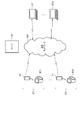
- FIG. 2 is a block diagram showing an overall configuration of an information processing system including the information processing apparatus according to the first embodiment.
- the information processing system includes, for example, a plurality of user terminals UT (in FIG. 2, UT1 to UTn, n is an arbitrary integer), a communication network NW, a server SV, and a plurality of doctor terminals DT (in FIG. 2).
- DT1 to DTm, m is an arbitrary integer).
- the user terminals UT1 to UTn, the server SV, and the doctor terminals DT1 to DTm can communicate with each other via the communication network NW.
- the user terminal UT is an example of the “user terminal UT” of the application example.
- the server SV is an example of the “information processing apparatus IPE” in the application example.
- each of the user terminals UT1 to UTn includes sphygmomanometers BT1 to BTn and portable information terminals IT1 to ITn.
- sphygmomanometers BT1 to BTn are not distinguished from one another, they are simply described as the sphygmomanometer BT.
- portable information terminals IT1 to ITn are not distinguished from one another, they are simply described as a portable information terminal IT.
- the sphygmomanometer BT is, for example, a watch-type wearable terminal.
- the sphygmomanometer BT is attached to the wrist of a user (a person to be measured), and measures a blood pressure value and a pulse rate at user's operation or at a preset timing or time interval. Then, the sphygmomanometer BT transmits, for example, measurement data in which the blood pressure value of the user, the pulse rate of the user, and user information (for example, user ID) are linked to the portable information terminal IT by, for example, a wireless interface.
- the user ID is an identifier assigned to each user.
- the sphygmomanometer BT may measure only the blood pressure value of the user, or may measure only the pulse rate of the user.
- the measurement data includes the blood pressure value of the user and the user ID.
- the sphygmomanometer BT measures only the pulse rate of the user, for example, the measurement data includes the pulse rate of the user and the user ID.
- the sphygmomanometer BT is not limited to the type worn on the wrist, but may be a type in which the cuff is wound around the upper arm or the like or a stationary type.
- the sphygmomanometers BT1 to BTn may be different types of sphygmomanometers.
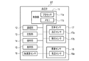
- FIG. 3 is a block diagram showing a configuration example of the sphygmomanometer BT.
- the sphygmomanometer BT includes a control unit 11, a communication unit 12, a storage unit 13, an operation unit 14, a display unit 15, an acceleration sensor 16, a living body sensor 17, and an environment sensor 18.
- the control unit 11 includes, for example, a processor 11a and a memory 11b.
- the control unit 11 realizes various operation control, data processing, and the like by the processor 11a executing a program using the memory 11b.
- the processor 11a is, for example, a central processing unit (CPU) including an arithmetic circuit or a micro processing unit (MPU).
- the memory 11 b includes, for example, a non-volatile memory storing a program executed by the processor 11 a and a volatile memory such as a random access memory (RAM) used as a working memory.
- the control unit 11 has a clock (not shown) and can measure the current date and time.
- the processor 11a can execute control of each unit and data processing by executing a program stored in the memory 11b or the storage unit 13. That is, the processor 11a performs operation control of each unit according to the operation signal from the operation unit 14, and performs data processing on measurement data measured by the biological sensor 17 and the environment sensor 18.
- the communication unit 12 is a communication interface for communicating with the portable information terminal IT.
- As the communication interface for example, an interface adopting a short distance wireless data communication standard such as Bluetooth (registered trademark) is used.
- the communication unit 12 transmits data to the portable information terminal IT and receives data from the portable information terminal IT.
- Communication by the communication unit 12 may be either wireless communication or wired communication.
- the storage unit 13 stores data of a program for controlling the sphygmomanometer BT, setting data for setting various functions of the sphygmomanometer BT, measurement data measured by the acceleration sensor 16, the biological sensor 17, and the environment sensor 18, and the like. Do.
- the storage unit 13 may be used as a working memory or the like when the program is executed.
- the operation unit 14 includes, for example, an operation device such as a touch panel (not shown) and operation buttons (operation keys).
- the operation unit 14 detects an operation by the user, and outputs an operation signal indicating the content of the operation to the control unit 11.
- the operation unit 14 is not limited to the touch panel or the operation button.
- the operation unit 14 recognizes, for example, a voice recognition unit that recognizes a user's voice operation instruction, a biometric authentication unit that authenticates a part of the user's living body, and a user's expression or gesture from an image of the user's face or body. An image recognition unit or the like may be provided.
- the display unit 15 includes, for example, a display screen (for example, an LCD (Liquid Crystal Display) or an EL (Electroluminescence) display), an indicator, and the like, and displays information in accordance with a control signal from the control unit 11.
- the acceleration sensor 16 detects the acceleration received by the main body of the sphygmomanometer BT. For example, the acceleration sensor obtains acceleration data of three or six axes. The acceleration data can be used to estimate the amount of activity (posture and / or motion) of the user wearing the sphygmomanometer BT.
- the control unit 11 can associate the acceleration data measured by the acceleration sensor 16 with the measurement date and time based on the date and time information, and output it as measurement data.
- the biometric sensor 17 measures biometric information of the user.
- the living body sensor 17 includes, for example, a blood pressure sensor 17a and a pulse sensor 17b.
- the blood pressure sensor 17a measures the blood pressure value of the user.
- the pulse sensor 17b measures the pulse rate of the user.
- pulse wave data, electrocardiogram data, heart rate data, body temperature data, etc. besides blood pressure value and pulse rate are assumed, and a sensor for measuring these measurement data is a living body
- the sensor 17 can be provided.
- the blood pressure sensor 17a is a continuous measurement or non-continuous measurement blood pressure sensor.
- the blood pressure sensor 17a is a blood pressure sensor capable of measuring values of blood pressure (for example, systolic blood pressure and diastolic blood pressure).
- the blood pressure sensor 17a may include, but is not limited to, a blood by pressure (BbB) blood pressure sensor that measures a blood pressure value for each heartbeat.
- BbB blood by pressure
- a blood pressure sensor using an oscillometric method, a pulse transit time (PTT) method, a tonometry method, an optical method, a radio wave method, an ultrasonic method, or the like can be applied.
- the oscillometric method is a method of pressing the upper arm with a cuff and measuring a blood pressure value with a vibration waveform in the cuff.
- the PTT method is a method of measuring a pulse wave propagation time and estimating a blood pressure value from the measured pulse wave propagation time.
- the tonometry method is a method in which a pressure sensor is brought into direct contact with a living body site through which an artery such as a radial artery of the wrist passes and blood pressure values are measured using information detected by the pressure sensor.
- the optical method, the radio wave method, and the ultrasonic method are methods in which light, radio waves or ultrasonic waves are applied to blood vessels and blood pressure values are measured from the reflected waves.
- the environmental sensor 18 includes a sensor that measures environmental information around the user and acquires the measured environmental data.
- the environment sensor 18 includes, for example, an air temperature sensor 18a.
- the environment sensor 18 may include a sensor that measures temperature, humidity, sound, light, and the like in addition to the air temperature.
- the environment sensor 18 may include a sensor that measures information (environment data) of an environment assumed to be directly or indirectly related to the fluctuation of the blood pressure value.
- the control unit 11 can output the measurement data (environment data) by linking the measurement date and time to set the measurement data measured by the environment sensor 18 based on the date and time information.
- the portable information terminal IT is, for example, a smart device (typically, a smartphone, a tablet terminal).
- the portable information terminal IT receives the measurement data transmitted from the sphygmomanometer BT, and transfers the measurement data to the server SV via the communication network NW.
- application software for managing measurement data may be installed.
- the portable information terminals IT1 to ITn may be terminals of different models.
- the portable information terminal IT may link the user ID to the measurement data received from the sphygmomanometer BT.
- This user ID may be stored in the storage unit 22 or the memory 21b.
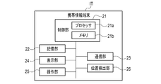
- FIG. 4 is a block diagram showing a configuration example of the portable information terminal IT.
- the portable information terminal IT includes a control unit 21, a storage unit 22, a communication unit 23, a display unit 24, an operation unit 25 and the like.
- the control unit 21 includes, for example, a processor 21a and a memory 21b.
- the basic configuration of the control unit 21 is the same as that of the control unit 11, and thus the detailed description is omitted.
- the storage unit 22 is configured of, for example, a semiconductor memory or a magnetic disk.
- the storage unit 22 may store a program executed by the processor 21 a of the control unit 21. Further, the storage unit 22 may store measurement data and the like supplied from the sphygmomanometer BT. The storage unit 22 may also store display data and the like displayed on the display unit 24.
- the communication unit 23 is a communication interface for communicating with the blood pressure monitor BT and the server SV.
- the communication unit 23 receives data from the blood pressure monitor BT or transmits an operation instruction to the blood pressure monitor BT.
- Communication by the communication unit 23 may be wireless communication or wired communication.
- the communication unit 23 transmits data to the server SV or receives data from the server SV via the network NW.
- Communication by the communication unit 23 may be wireless communication or wired communication.
- the network NW will be described assuming, for example, the Internet, but is not limited to this, and may be another type of network such as a LAN, using a communication cable such as a USB cable 1 It may be paired-one communication.
- the display unit 24 includes a display screen (for example, an LCD or an EL display).
- the display unit 24 controls the display content to be displayed on the display screen by the control of the control unit 21.
- the operation unit 25 transmits an operation signal corresponding to the operation by the user to the control unit 21.
- the operation unit 25 is, for example, a touch panel provided on the display screen of the display unit 24.
- the operation unit 25 is not limited to the touch panel, and may be an operation button, a keyboard, a mouse, and the like.
- the operation unit 25 includes a voice recognition unit that recognizes a user's voice operation instruction, a biometric authentication unit that authenticates a part of the user's living body, or an image recognition unit that recognizes a user's expression or gesture. It may be
- the portable information terminal IT may transmit the blood pressure value and the pulse rate manually input by the user to the server SV.
- the doctor terminal DT is, for example, a fixed installation personal computer, a portable notebook personal computer or a tablet terminal.
- the doctor terminal DT can transmit and receive data to and from the server SV by using, for example, a browser. Specifically, the doctor terminal DT can transmit information on the user to the server SV using the browser, and can display the information sent from the server SV.
- the doctor terminals DT1 to DTm may be terminals of different models.
- the doctor terminal DT may receive measurement data from the sphygmomanometer BT and perform various processes.
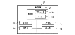
- FIG. 5 is a block diagram showing a configuration example of the doctor terminal DT.
- the doctor terminal DT includes a control unit 31, a storage unit 32, a communication unit 33, a display unit 34, an operation unit 35, and the like.
- the control unit 31 includes, for example, a processor 31a and a memory 31b.
- the basic configuration of the control unit 31 is the same as that of the control unit 11, and thus detailed description will be omitted.
- the storage unit 32 includes, for example, a magnetic disk, a semiconductor memory, an optical disk, a magneto-optical disk, or the like.
- the storage unit 32 may store a program executed by the processor 31 a of the control unit 31.
- the communication unit 33 is a communication interface for communicating with the server SV.
- the communication unit 33 transmits data to the server SV or receives data from the server SV via the network NW.
- Communication by the communication unit 33 may be wireless communication or wired communication.
- the communication unit 33 is described on the assumption that the communication unit 33 communicates with the server SV via another type of network such as a LAN, but the present invention is not limited thereto, and serial communication is performed using a communication cable. You may include what you do.
- the display unit 34 includes a display screen (for example, an LCD or an EL display).
- the display unit 34 controls the display content to be displayed on the display screen under the control of the control unit 31.
- the operation unit 35 transmits an operation signal corresponding to the operation by the user to the control unit 31.
- the operation unit 35 is, for example, a touch panel provided on the display screen of the display unit 34.
- the operation unit 35 is not limited to the touch panel, and may be an operation button, a keyboard, a mouse, and the like.
- the operation unit 35 includes a voice recognition unit that recognizes a user's voice operation instruction, a biometric authentication unit that authenticates a part of the user's living body, or an image recognition unit that recognizes a user's expression or gesture. It may be
- the server SV is a server computer.
- the server SV is described on the assumption that a general-purpose computer device has a program (software) installed so as to perform processing described later.
- the server SV accumulates measurement data transmitted from the user terminal UT.
- the server SV may transmit measurement data of the user according to access from the doctor terminal DT installed at a medical institution, for example, to provide for health guidance or diagnosis of the user.
- An example of functions realized by the server SV will be described later.
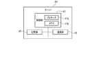
- FIG. 6 is a block diagram showing a configuration example of the server SV.
- the server SV includes a control unit 41, a storage unit 42, and a communication unit 43.
- the control unit 41 includes, for example, a processor 41a and a memory 41b.
- the basic configuration of the control unit 41 is the same as that of the control unit 11, and thus detailed description will be omitted.
- the storage unit 42 is configured of, for example, a magnetic disk, a semiconductor memory, an optical disk, a magneto-optical disk, or the like.
- the storage unit 42 stores various measurement data acquired from the user terminal UT.
- the storage unit 42 may store a program executed by the processor 41 a of the control unit 41.
- the communication unit 43 is a communication interface for communicating with the user terminal UT or the doctor terminal DT.
- the communication unit 43 transmits data to the user terminal UT or the doctor terminal DT or receives data from the user terminal UT or the doctor terminal DT via the network NW.
- Communication by the communication unit 43 may be wireless communication or wired communication.
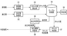
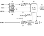
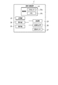
- FIG. 7 is a block diagram schematically illustrating an example of a functional configuration of the server SV according to the present embodiment.
- the server SV develops the program stored in the storage unit 42 in the memory 41 b. Then, the control unit 41 causes the processor 41a to interpret and execute the program developed in the memory 41b to control each component.
- the server SV includes a pulse rate acquisition unit 51, a blood pressure value acquisition unit 52, a stress degree calculation unit 53, a table management unit 54, a determination unit 55, and a blood pressure determination unit 56. Functions as a computer including the stress determination unit 57 and the blood pressure type determination unit 58.
- the pulse rate acquisition unit 51 is an example of the “pulse rate acquisition unit IPEPA” of the application example.
- the blood pressure value acquisition unit 52 is an example of the “blood pressure value acquisition unit IPEBA” in the application example.
- the stress degree calculation unit 53 is an example of the “tension degree calculation unit IPEC” in the application example.
- the table management unit 54 is an example of the “storage unit IPEM” in the application example.
- the determination unit 55, the blood pressure determination unit 56, the stress determination unit 57, and the blood pressure type determination unit 58 are examples of the “blood pressure type determination unit IPEB” in the application example.
- the pulse rate acquisition unit 51 receives the pulse rate via the network NW, and supplies the pulse rate to the stress degree calculation unit 53.
- the stress degree calculator 53 calculates the stress degree (tension degree) based on the pulse rate. Specifically, the stress level calculation unit 53 calculates the stress level associated with the user ID based on the pulse rate associated with the user ID. The stress degree calculation unit 53 supplies the stress degree to the table management unit 54 when the stress degree is calculated from the pulse rate of the user.
- the blood pressure value acquisition unit 52 receives the blood pressure value via the network NW, and supplies the blood pressure value to the table management unit 54.
- the table management unit 54 has a table for each user. By managing the table for each user, it becomes possible to properly manage the information of a plurality of measured persons.
- the table is expanded in, for example, the memory 41 b or the storage unit 42 of the server SV.
- the table stores, for example, the blood pressure value received via the network NW, and the stress degree received from the stress degree calculation unit 53.
- the specific structural example of a table is mentioned later.
- the table management unit 54 enables display on the portable information terminal IT or the doctor terminal DT, for example, in accordance with a user's instruction via the portable information terminal IT or the doctor terminal DT.
- the determination unit 55 determines the content of data stored in the table management unit 54 based on an instruction from the user, and controls the operation of the table management unit 54.
- the blood pressure determination unit 56 determines whether the blood pressure value supplied from the table management unit 54 exceeds a threshold. Then, the blood pressure determination unit 56 supplies the determination result (blood pressure determination result) to the blood pressure type determination unit 58.
- the stress determination unit 57 determines the stress of the user to be determined based on the degree of stress supplied from the table management unit 54. Specifically, the stress determination unit 57 compares the stress level of the user in normal times and the stress level at the time of blood pressure measurement. Then, the stress determination unit 57 determines whether or not the degree of stress at the time of blood pressure measurement exceeds the threshold with respect to the degree of stress at normal times. The stress determination unit 57 supplies the determination result (stress determination result) to the blood pressure type determination unit 58.
- the blood pressure type determination unit 58 determines the type of blood pressure based on the stress determination result supplied from the stress determination unit 57 and the blood pressure determination result supplied from the blood pressure determination unit 56. Then, the blood pressure type determination unit 58 outputs the determination result.
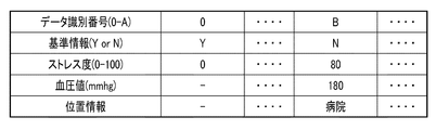
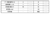
- FIG. 8 is a diagram showing an example of the structure of the table. For simplicity, the structure of the table will be described focusing on one user.
- the table stores, for example, data identification numbers, reference information, stress levels, and blood pressure values for each user information (for example, user ID) included in measurement data.
- the reference information is information indicating whether or not the stress level is a reference value in the blood pressure type determination operation described later.
- the information processing system determines the pulse rate (stress level) at the time of blood pressure value measurement based on the normal pulse rate (stress level), and determines the stress state of the user (subject to be measured) Do. Therefore, it is necessary to determine which pulse rate is the normal pulse rate. Therefore, the user needs to set the reference information of the normal pulse rate to “Y” and set the reference information of the pulse rates other than normal to “N”. That is, the reference information of the stress degree which is the reference value is set as "Y", and the reference information of the stress degree which is not the reference is set as "N".
- Method 1 For example, when the doctor manually inputs the normal pulse rate of the subject via the doctor terminal DT, the doctor inputs the normal pulse rate of the subject via the operation unit 35 and the reference information Is set to "Y". Thereby, the pulse rate and the reference information are linked.
- Method 2 When the user measures the pulse rate with the sphygmomanometer BT, the user inputs reference information (whether normal or not) via the operation unit 14. The control unit 11 further associates reference information with the measurement data (pulse rate) based on the input from the operation unit 14.
- Method 3 The user inputs information (whether normal or not) related to reference information through the operation unit 25 for measurement data (pulse rate) transferred from the sphygmomanometer BT to the portable information terminal IT.
- the control unit 21 further associates reference information with measurement data (pulse rate) based on an input from the operation unit 25.
- the above-described methods 1 to 3 are an example, and a method of correlating reference information and measurement data can be appropriately applied.
- the stress level is linked to the user ID. Further, the blood pressure value is linked to the user ID. Therefore, when the table management unit 54 receives various information, the table management unit 54 stores data in a table related to the user ID.
- blood pressure information may not be stored in a column (in the vertical axis direction in FIG. 8) related to the stress level in normal times (the stress level in which the reference information is Y).
- the table management unit 54 can output the corresponding blood pressure value and the degree of stress from the user ID, the data identification number, the reference information, and the like.
- the user ID is configured by an arbitrary combination of numbers and characters.
- the data identification number is assigned, for example, sequentially from 0, but is not limited thereto.
- the data identification number may be composed of any combination of numbers and letters.
- the degree of stress is expressed, for example, between 0 and 100, but is not limited thereto. The degree of stress can be appropriately changed according to the calculation method or the like. The degree of stress according to the present embodiment is determined to be large in the case of 51 to 100, for example.
- FIG. 9 is a flowchart illustrating an example of the processing procedure of the information processing system.
- the process sequence demonstrated below is only an example, and each process may be changed as much as possible.
- steps may be omitted, replaced, or added as appropriate, according to the embodiment.
- Step S101 The server SV receives measurement data via the network NW.
- NW Network NW
- the server SV receives only the normal pulse rate from the sphygmomanometer BT.
- the user may measure only the normal pulse rate with the sphygmomanometer BT.
- the operator of the sphygmomanometer BT supplies the normal pulse rate to the server SV via the sphygmomanometer BT.
- the server SV pulse rate acquisition unit 51
- the operator of the sphygmomanometer BT sets the reference information of the normal pulse rate to “Y” in the sphygmomanometer BT or the portable information terminal IT, and further links the user ID to the pulse rate.
- the server SV receives the normal pulse rate of the user (person to be measured) who does not possess the blood pressure monitor BT.
- the user who does not possess the blood pressure monitor BT measures, for example, the pulse rate at normal times by another terminal or the user himself.
- the user transmits or manually inputs the normal pulse rate to the portable information terminal IT or the doctor terminal DT.
- the user supplies the normal pulse rate to the server SV via the portable information terminal IT and the doctor terminal DT.
- the server SV pulse rate acquisition unit 51
- receives the normal pulse rate At this time, in the portable information terminal IT and the doctor terminal DT, the reference information of the pulse rate at normal times is set as "Y", and the user ID is further linked to the pulse rate.
- the server SV receives a pulse rate and a blood pressure value for determination from the sphygmomanometer BT.
- the user may measure the pulse rate and the blood pressure value by the sphygmomanometer BT.
- the user supplies the pulse rate and the blood pressure value to the server SV via the sphygmomanometer BT.
- the server SV (the pulse rate acquisition unit 51 and the blood pressure value acquisition unit 52) receives the pulse rate and the blood pressure value.
- the user sets the reference information of the pulse rate and the blood pressure value to “N” in the blood pressure monitor BT or the portable information terminal IT, and further links the user ID to the pulse rate and the blood pressure value.
- the server SV receives a pulse rate and a blood pressure value for determination of a user (person to be measured) who does not have the blood pressure monitor BT will be described.
- the user who does not possess the blood pressure monitor BT measures, for example, the pulse rate and the blood pressure value with another terminal provided in a medical institution or the like.
- the user transmits or manually inputs the measured pulse rate and blood pressure value to the portable information terminal IT or the doctor terminal DT.
- the user supplies the pulse rate and the blood pressure value to the server SV via the portable information terminal IT and the doctor terminal DT.
- the server SV receives the pulse rate and the blood pressure value for determination.
- the user sets the reference information of the normal pulse rate to “Y” in the portable information terminal IT or the doctor terminal DT, and further links the user ID to the pulse rate.
- each terminal is not limited to the user but may be, for example, a doctor.
- Step S102 When the server SV receives the measurement data to the server SV via the network NW, the stress degree calculator 53 calculates the stress degree based on the pulse rate.
- the table management unit 54 stores the reference information, the degree of stress, and the blood pressure value in a table based on the user ID.
- the table management unit 54 When the table management unit 54 receives the blood pressure value or the stress level, it stores the reference information, the stress level, and the blood pressure value in the table corresponding to the user ID. At this time, when there is no table related to the user ID, the table management unit 54 generates a table related to the user ID. Then, the table management unit 54 stores the reference information, the degree of stress, and the blood pressure value in the column with the data identification number “0”. If there is a table relating to the user ID, the table management unit 54 increments the latest data identification number by one, generates a new column, and stores the reference information, the stress level, and the blood pressure value.
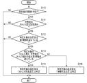
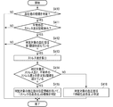
- FIG. 10 is a flowchart illustrating an example of the processing procedure of the information processing system.
- the process sequence demonstrated below is only an example, and each process may be changed as much as possible.
- steps may be omitted, replaced, or added as appropriate, according to the embodiment.
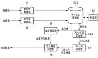
- Step S110 The control unit 41 of the server SV determines whether to determine the type of blood pressure.
- the instruction as to whether or not to determine the type of blood pressure is received from, for example, the portable information terminal IT or the doctor terminal DT.
- the diagnostician of the user can select the blood pressure value to be determined via the portable information terminal IT or the doctor terminal DT by referring to the above-described table, for example.
- Step S111 If it is determined that the type of blood pressure is to be determined (YES in step S110), the determination unit 55 determines whether the stress level of normal serving as the reference value is stored in the table. When determining that the normal stress level is not stored in the table (step S111, NO), the determination unit 55 cancels the blood pressure type determination operation.
- Step S112 When determining unit 55 determines that the stress level in normal condition is stored in the table (YES in step S111), blood pressure determining unit 56 determines whether the blood pressure value to be determined exceeds the first threshold. to decide. More specifically, the blood pressure determination unit 56 determines whether the blood pressure value to be determined exceeds the first threshold.
- the first threshold is a value for determining that the blood pressure value to be determined is classified as high blood pressure. That is, when the blood pressure value of the determination target exceeds the first threshold, it is determined that the blood pressure value of the determination target does not exceed the first threshold, and it is determined that the blood pressure value of the determination target is not classified as high blood pressure.
- the first threshold is stored, for example, in the memory 41 b or the storage unit 42 of the server SV. Then, for example, the doctor can arbitrarily set the first threshold via the doctor terminal DT or the like.
- the blood pressure determination unit 56 ends the blood pressure type determination operation as the blood pressure value of the determination target is not classified as hypertension.
- Step S113 When it is determined by the blood pressure determination unit 56 that the blood pressure value to be determined exceeds the first threshold (YES in step S112), the stress determination unit 57 determines the stress level associated with the blood pressure value to be determined (determination target It is determined whether or not the difference between the stress level) and the normal stress level exceeds the second threshold.
- the second threshold is a value for determining the magnitude of stress applied to the user at the time of blood pressure value measurement. That is, when the difference between the stress level at the time of blood pressure measurement and the stress level at normal time exceeds the second threshold, it is determined that the user is stressed at the time of blood pressure measurement, and the stress degree at blood pressure measurement When the difference between the normal stress level does not exceed the second threshold, it is determined that the user is not stressed at the time of blood pressure measurement.
- the second threshold is stored, for example, in the memory 41 b or the storage unit 42 of the server SV. Then, for example, the doctor can arbitrarily set the second threshold via the doctor terminal DT or the like.
- the process of determining the type of hypertension is performed only when the blood pressure value to be determined is classified as high blood pressure. Therefore, when the measured blood pressure value is not classified as high blood pressure, the process of determining the type of high blood pressure is omitted, and the processing load on the server SV is reduced accordingly.
- Step S114 When it is determined by the stress determination unit 57 that the difference between the stress level to be determined and the stress level in normal time exceeds the second threshold (YES in step S113), the blood pressure type determination unit 58 determines It determines that the blood pressure of the blood pressure value is suspected of "stress-induced hypertension" and outputs the determination result.
- the determination result may be stored in the memory 41 b or the storage unit 42 of the server SV, or may be output to the portable information terminal IT or the doctor terminal DT.
- Step S115 When it is determined by the stress determination unit 57 that the difference between the stress level to be determined and the stress level to be determined does not exceed the second threshold (NO in step S113), the blood pressure type determination unit 58 determines It determines that the blood pressure of the blood pressure value is "sustained hypertension" and outputs the determination result.
- the determination result may be stored in the memory 41 b or the storage unit 42 of the server SV, or may be output to the portable information terminal IT or the doctor terminal DT.
- the blood pressure type determination unit 58 may output information to recommend the normal measurement of blood pressure to the person to be measured.
- the information processing system can determine the type of blood pressure by determining any blood pressure value and stress level based on the stress level in normal times. .
- FIG. 11 is a diagram showing the relationship between the blood pressure value and the degree of stress related to persistent hypertension.
- FIG. 12 is a diagram showing the relationship between the blood pressure value and the degree of stress related to stress-induced hypertension.
- the user does not measure the blood pressure value during the first period (normal time), but measures only the pulse rate. Then, the user measures the blood pressure value and the pulse rate in the second period. The case where the type of blood pressure of the blood pressure value measured in the second period is determined under the above conditions will be described.
- the blood pressure value is higher than the first threshold, but the difference between the stress degree in the second period and the stress degree in the first period is lower than the second threshold.
- the blood pressure value exceeds the first threshold, and the difference between the stress degree in the second period and the stress degree in the first period is the second threshold.
- the blood pressure values in the second period are the same, but the stress levels are different. If the information processing system refers only to the blood pressure value in the second period without considering the degree of stress, it is not possible to determine the type of blood pressure.
- the information processing system according to the first embodiment can determine the stress state of the user by referring to the stress level at the time of blood pressure measurement (second period). As a result, the information processing system according to the first embodiment can appropriately determine the type of blood pressure.
- normal blood pressure values such as home blood pressure are essential to determine the type of hypertension.
- the type of high blood pressure can be used even for people who can not obtain normal blood pressure values, for example, people who do not have a habit of measuring blood pressure at home or patients who are neglecting blood pressure measurement. It is possible to determine.
- normal blood pressure measurement is recommended when the above-mentioned stressful hypertension or persistent hypertension is suspected. Therefore, if the subject performs normal blood pressure measurement in response to this message, the doctor can confirm the diagnosis of stressful hypertension or persistent hypertension based on the measured value.
- Second Embodiment The second embodiment will be described.
- a method of more specifically identifying the type of blood pressure will be described by further considering position information (measurement position information) in the blood pressure type determination operation.
- the basic configuration and basic operation of the information processing system including the information processing apparatus according to the second embodiment are similar to those of the information processing system including the information processing apparatus according to the first embodiment described above. Therefore, the description of the matters described in the above-described first embodiment and the matters that can be easily analogized from the above-described first embodiment will be omitted.
- the user terminal UT also acquires position information when measuring the blood pressure value and pulse rate of the user (person to be measured).
- the position detection unit of the portable information terminal IT acquires position information of the user.
- the control unit 21 of the portable information terminal IT further associates position information with measurement data (for example, a blood pressure value, a pulse rate, and a user ID).
- the sphygmomanometer BT may perform acquisition of position information. In that case, the control unit 11 of the sphygmomanometer BT links the position information to the measurement data.
- FIG. 13 is a block diagram showing a configuration example of the portable information terminal IT.
- the portable information terminal IT includes a control unit 21, a storage unit 22, a communication unit 23, a display unit 24, an operation unit 25, a position detection unit 26 and the like.
- the position detection unit 26 includes, for example, a GPS (Global Positioning System), operates according to a control signal from the control unit 21, and can detect the position of the portable information terminal IT from information obtained from GPS satellites.
- GPS Global Positioning System
- FIG. 14 is a block diagram schematically illustrating an example of a functional configuration of the server SV according to the present embodiment. It differs from the first embodiment in that the table stores position information.
- the control unit 41 of the server SV develops the program stored in the storage unit 42 in the memory 41 b. Then, the control unit 41 causes the processor 41a to interpret and execute the program developed in the memory 41b to control each component.
- the server SV includes the pulse rate acquisition unit 51, the blood pressure value acquisition unit 52, the stress degree calculation unit 53, the table management unit 54-1, the determination unit 55, the blood pressure determination unit 56, and the stress determination unit 57. And functions as a computer including the blood pressure type determination unit 58-1 and the position information acquisition unit 59.
- the position information acquisition unit 59 receives the position information via the network NW and supplies it to the table management unit 54-1.
- the table management unit 54-1 has a table for each user.
- the table is expanded in, for example, the memory 41 b or the storage unit 42 of the server SV.
- the table stores, for example, blood pressure values, position information, and stress levels.
- the specific structural example of a table is mentioned later.
- the table management unit 54-1 enables display on the portable information terminal IT or the doctor terminal DT, for example, in accordance with a user's instruction via the portable information terminal IT or the doctor terminal DT.
- the blood pressure type determination unit 58-1 includes the position information supplied from the table management unit 54-1, the blood pressure determination result supplied from the blood pressure determination unit 56, and the stress determination unit supplied from the stress determination unit 57. Based on the type of blood pressure is determined. Then, the blood pressure type determination unit 58-1 outputs the determination result.
- FIG. 15 is a diagram showing an example of the structure of the table. For simplicity, the structure of the table will be described focusing on one user.
- the table stores, for example, data identification numbers, reference information, stress levels, blood pressure values, and position information for each user information (for example, user ID) included in measurement data.
- Position information is information for grasping a measurement position of a blood pressure value and a pulse rate of a user (a person to be measured). Although the name of a place is shown as an example in FIG. 15, the present invention is not limited to this, and may be an address, latitude and longitude, and the like.
- the blood pressure information and the position information may not be stored in the column regarding the stress level in normal times (the stress level in which the reference information is Y).
- Method 1 When the portable information terminal IT receives measurement data (blood pressure value and pulse value) from the sphygmomanometer BT at the communication unit 23, the position detection unit 26 of the portable information terminal IT detects the position information of the user (subject) get. And control part 21 of personal digital assistant IT ties position information to measurement data.
- measurement data blood pressure value and pulse value
- Method 2 When the doctor terminal DT receives the measurement data (blood pressure value and pulse value) by the communication unit 33, the operation unit 35 inputs position information of the user (person to be measured). And control part 31 of doctor terminal DT ties position information to measurement data.
- the method 1 and the method 2 which were mentioned above are an example, and it is applicable suitably about how to attach position information and measurement data.
- FIG. 16 is a flowchart illustrating an example of the processing procedure of the information processing system.
- the process sequence demonstrated below is only an example, and each process may be changed as much as possible.
- steps may be omitted, replaced, or added as appropriate, according to the embodiment.
- the operation of storing the normal pulse rate in the server SV is the same as the operation described in FIG.
- an operation of storing the pulse rate and the blood pressure value to be subjected to the blood pressure type determination operation in the server SV will be described.
- step S201 The operation of step S201 is the same as the operation of step S101 of FIG. 9 (in particular, cases 3 and 4).
- the position information acquisition unit 59 receives the position information via the network NW.
- Step S203 The operation of step S203 is the same as the operation of step S102 of FIG.
- the table management unit 54-1 stores reference information, a stress level, a blood pressure value, and position information in a table based on the user ID.
- FIG. 17 is a flowchart illustrating an example of the processing procedure of the information processing system.
- the process sequence demonstrated below is only an example, and each process may be changed as much as possible.
- steps may be omitted, replaced, or added as appropriate, according to the embodiment.
- steps S210 to S213 are the same as the operations of steps S110 to S113 of FIG.
- Step S214 If it is determined that the difference between the stress level to be determined and the stress level in normal time exceeds the second threshold (YES in step S213), the blood pressure type determination unit 58-1 determines the stress level to be determined and The position information associated with the blood pressure value to be determined is determined.
- the blood pressure type determination unit 58-1 determines the type of blood pressure based on the position information. Specifically, when it is determined from the position information that the measurement position is "hospital”, the blood pressure type determination unit 58-1 determines that the blood pressure value of the determination target is "white coat hypertension", and the determination result is Output. When it is determined from the position information that the measurement position is “work place”, the blood pressure type determination unit 58-1 determines that the blood pressure value to be determined is “work hypertension”, and outputs the determination result.
- the determination result may be stored in the memory 41 b or the storage unit 42 of the server SV, or may be output to the portable information terminal IT or the doctor terminal DT. Note that any method may be used to determine the position from the position information.
- Step S215 The operation of step S215 is the same as the operation of step S115 of FIG.
- the information processing system more precisely determines the type of blood pressure by further considering the position information in the blood pressure type determination operation described in the first embodiment.
- the third embodiment will be described.
- the third embodiment differs from the first embodiment in that the calculation timing of the stress level is different.
- the basic configuration and basic operation of the information processing system including the information processing apparatus according to the third embodiment are the same as those of the information processing system including the information processing apparatus according to the first embodiment described above. Therefore, the description of the matters described in the above-described first embodiment and the matters that can be easily analogized from the above-described first embodiment will be omitted.
- FIG. 18 is a block diagram schematically illustrating an example of a functional configuration of the server SV according to the present embodiment.
- the second embodiment differs from the first embodiment in that the table stores the pulse rate instead of the stress level. Further, in the third embodiment, the calculation timing of the stress level is different from that of the first embodiment.
- the control unit 41 of the server SV develops the program stored in the storage unit 42 in the memory 41 b. Then, the control unit 41 causes the processor 41a to interpret and execute the program developed in the memory 41b to control each component.
- the server SV includes the pulse rate acquisition unit 51, the blood pressure value acquisition unit 52, the stress degree calculation unit 53-1, the table management unit 54-2, the determination unit 55, the blood pressure determination unit 56, and the stress determination It functions as a computer including the unit 57 and the blood pressure type determination unit 58.
- the table management unit 54-2 includes a table for each user.
- the table is expanded in, for example, the memory 41 b or the storage unit 42 of the server SV.
- the table stores blood pressure values and pulse rates received via the network NW.
- the specific structural example of a table is mentioned later.
- the table management unit 54-2 can be displayed on the portable information terminal IT or the doctor terminal DT, for example, according to an instruction of the user via the portable information terminal IT or the doctor terminal DT.
- the stress degree calculation unit 53-1 calculates the stress degree based on the pulse rate received through the table management unit 54-2.
- FIG. 19 is a diagram showing an example of the structure of the table. For simplicity, the structure of the table will be described focusing on one user.
- the table stores, for example, a data identification number, reference information, a pulse rate, and a blood pressure value for each user ID included in measurement data.
- the blood pressure information may not be stored in the column related to the normal pulse rate (the pulse rate of reference information is Y).
- FIG. 20 is a flowchart illustrating an example of the processing procedure of the information processing system.
- the process sequence demonstrated below is only an example, and each process may be changed as much as possible.
- steps may be omitted, replaced, or added as appropriate, according to the embodiment.
- Step S301 The operation of step S301 is the same as the operation of step S101 of FIG.
- the table management unit 54-2 stores the reference information, the pulse rate, and the blood pressure value in the table based on the user ID.
- FIG. 21 is a flowchart illustrating an example of the processing procedure of the information processing system.
- the process sequence demonstrated below is only an example, and each process may be changed as much as possible.
- steps may be omitted, replaced, or added as appropriate, according to the embodiment.
- steps S310 to S312 are similar to the operations of steps S110 to S112 of FIG.
- Step S313 When it is determined by the blood pressure determination unit 56 that the blood pressure value difference to be determined exceeds the first threshold (YES in step S312), the stress degree calculation unit 53-1 is supplied from the table management unit 54-2. The degree of stress is calculated based on the pulse rate.
- the information processing system can obtain the same effects as the effects described in the first embodiment even when the calculation timing of the stress level is changed.
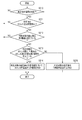
- FIG. 22 is a block diagram schematically illustrating an example of a functional configuration of the server SV according to the present embodiment.
- the control unit 41 of the server SV develops the program stored in the storage unit 42 in the memory 41 b. Then, the control unit 41 causes the processor 41a to interpret and execute the program developed in the memory 41b to control each component.
- the server SV includes the pulse rate acquisition unit 51, the blood pressure value acquisition unit 52, the stress degree calculation unit 53-1, the table management unit 54-3, the determination unit 55, the blood pressure determination unit 56, and the stress determination It functions as a computer including the unit 57, the blood pressure type determination unit 58-1, and the position information acquisition unit 59.
- the table management unit 54-3 has a table for each user.
- the table is expanded in, for example, the memory 41 b or the storage unit 42 of the server SV.
- the table stores blood pressure values, pulse rates, and position information received via the network NW.
- the specific structural example of a table is mentioned later.
- the table management unit 54-3 enables display on the portable information terminal IT or the doctor terminal DT, for example, in accordance with a user's instruction via the portable information terminal IT or the doctor terminal DT.
- FIG. 23 is a diagram showing an example of the structure of the table. For simplicity, the structure of the table will be described focusing on one user.
- the table stores, for example, a data identification number, reference information, a pulse rate, a blood pressure value, and position information for each user ID included in measurement data.
- the blood pressure information and the position information may not be stored in the column related to the normal pulse rate (the pulse rate of the reference information Y).
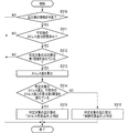
- FIG. 24 is a flowchart illustrating an example of the processing procedure of the information processing system.
- the process sequence demonstrated below is only an example, and each process may be changed as much as possible.
- steps may be omitted, replaced, or added as appropriate, according to the embodiment.
- steps S401 and S402 are the same as the operations of steps S201 and S202 of FIG.
- the table management unit 54-3 stores reference information, a pulse rate, a blood pressure value, and position information in a table based on the user ID.
- FIG. 25 is a flowchart illustrating an example of the processing procedure of the information processing system.
- the process sequence demonstrated below is only an example, and each process may be changed as much as possible.
- steps may be omitted, replaced, or added as appropriate, according to the embodiment.
- steps S410 to S412 are the same as the operations of steps S110 to S112 of FIG.
- Step S413 The operation of step S413 is the same as the operation of step S313 of FIG.
- step S414 The operation of step S414 is the same as the operation of step S113 of FIG.
- step S415 The operation of step S415 is the same as the operation of step S214 of FIG.
- Step S416 The operation of step S416 is the same as the operation of step S115 of FIG.
- the fifth embodiment will be described.
- an example in which the user's pulse rate is measured by a portable information terminal will be described.
- the basic configuration and the basic operation of the information processing system including the information processing apparatus according to the fifth embodiment are the same as the information processing system including the information processing apparatus according to the first to fourth embodiments described above. is there. Therefore, the description of the matters described in the above-described first to fourth embodiments and the matters that can be easily analogized from the above-described first to fourth embodiments will be omitted.
- the sphygmomanometer BT measures the pulse rate of a user (a person to be measured)
- the pulse may be measured at a terminal other than the sphygmomanometer BT.
- the portable information terminal measures a pulse rate
- FIG. 26 is a block diagram showing a configuration example of the portable information terminal IT.
- the portable information terminal IT includes a control unit 21, a storage unit 22, a communication unit 23, a display unit 24, an operation unit 25, a position detection unit 26, a pulse sensor 27, and the like.
- the pulse sensor 27 has, for example, the same configuration as the pulse sensor 17b of the sphygmomanometer BT.
- the first method is to measure only the pulse rate
- the second method is to measure the pulse rate and the blood pressure value simultaneously.
- the method of measuring a pulse rate with the pulse sensor 27 of portable information terminal IT can be considered, while measurement of the blood pressure value by sphygmomanometer BT is performed.
- control unit 21 when the user (a person to be measured) starts measuring the pulse rate on the portable information terminal IT, the control unit 21 indicates that the blood pressure monitor BT has started measuring the pulse rate via the communication unit 23. Notice.
- control unit 11 of the sphygmomanometer BT receives notification that measurement of the pulse rate has been started, measurement of the blood pressure value of the user is started.
- control unit 11 of the sphygmomanometer BT notifies that via the communication unit 12 to the portable information terminal IT.
- the control unit 21 of the portable information terminal IT ends the measurement of the pulse rate when it receives that the measurement of the blood pressure value is completed.
- control unit 21 of the portable information terminal IT links the pulse rate to the blood pressure value (measurement data) transmitted from the sphygmomanometer BT.
- the method mentioned above is an example. Other methods can be applied as long as it can ensure that the measurement of the blood pressure value and the timing of the measurement of the pulse rate are approximately simultaneous.
- the information processing system measures the pulse rate and the blood pressure value at different terminals. Also in this case, the same effects as those of the first to fourth embodiments described above can be obtained.
- the server SV has been described as an example of the “information processing apparatus IPE” of the application example.
- the “information processing apparatus IPE” of the application example may be realized by a plurality of servers SV.
- the “information processing apparatus IPE” of the application example may be the portable information terminal IT, the doctor terminal DT, or the like.
- the control unit 21 of the portable information terminal IT develops the program stored in the storage unit 22 in the memory 21 b. Then, the control unit 21 interprets and executes the program developed in the memory 21 b by the processor 21 a to realize the above-described functional configuration.
- the control unit 31 of the doctor terminal DT develops the program stored in the storage unit 32 in the memory 31 b. Then, the control unit 31 causes the processor 31a to interpret and execute the program developed in the memory 31b to realize the above-described functional configuration.
- reference information may be derived based on position information included in measurement data.
- the table management unit 54-1 sets the reference information to “Y” when determining from the received position information that the position to be measured stays at normal times.
- the table management unit 54-1 sets the reference information to “N” when it is determined from the received position information that the position to be measured does not stay at normal times.
- this operation subject may be another terminal. For example, it may be a sphygmomanometer, a portable information terminal, a doctor terminal or the like.
- the present invention is not limited to the above embodiment as it is, and at the implementation stage, the constituent elements can be modified and embodied without departing from the scope of the invention.
- various inventions can be formed by appropriate combinations of a plurality of components disclosed in the above embodiments. For example, some components may be deleted from all the components shown in the embodiment. Furthermore, components in different embodiments may be combined as appropriate.
- a blood pressure value acquisition unit that acquires the blood pressure value of the subject measured by the blood pressure measurement unit;
- a pulse rate acquisition unit that acquires a first pulse rate under normal conditions of the person to be measured and a second pulse rate of the person under measurement in a time zone in which the blood pressure value is measured;
- a first degree of tension of the subject's autonomic nerve is calculated based on the first pulse rate, and a second degree of autonomic nerve of the subject is calculated based on the second pulse rate.
- Department A determination unit that determines the type of blood pressure of the blood pressure value based on the blood pressure value, the first degree of tension, and the second degree of tension;
- An information processing method performed by an apparatus for processing a blood pressure value measured by a blood pressure measurement unit comprising: Acquiring the blood pressure value of the subject measured by the blood pressure measurement unit; Acquiring a first pulse rate of the subject at normal times and a second pulse rate of the subject at a time zone in which the blood pressure value is measured; A step of calculating a first degree of tension of the subject's autonomic nerve based on the first pulse rate and calculating a second degree of autonomic nerve of the subject based on the second pulse rate When, Determining the type of blood pressure of the blood pressure value based on the blood pressure value, the first degree of tension, and the second degree of tension.
Landscapes
- Health & Medical Sciences (AREA)
- Life Sciences & Earth Sciences (AREA)
- Engineering & Computer Science (AREA)
- Cardiology (AREA)
- Medical Informatics (AREA)
- Pathology (AREA)
- Biomedical Technology (AREA)
- Heart & Thoracic Surgery (AREA)
- Biophysics (AREA)
- Molecular Biology (AREA)
- Surgery (AREA)
- Animal Behavior & Ethology (AREA)
- General Health & Medical Sciences (AREA)
- Public Health (AREA)
- Veterinary Medicine (AREA)
- Physics & Mathematics (AREA)
- Physiology (AREA)
- Vascular Medicine (AREA)
- Psychiatry (AREA)
- Ophthalmology & Optometry (AREA)
- Developmental Disabilities (AREA)
- Computer Vision & Pattern Recognition (AREA)
- Signal Processing (AREA)
- Child & Adolescent Psychology (AREA)
- Artificial Intelligence (AREA)
- Educational Technology (AREA)
- Hospice & Palliative Care (AREA)
- Psychology (AREA)
- Social Psychology (AREA)
- Measuring Pulse, Heart Rate, Blood Pressure Or Blood Flow (AREA)
- Measurement Of The Respiration, Hearing Ability, Form, And Blood Characteristics Of Living Organisms (AREA)
- Measuring And Recording Apparatus For Diagnosis (AREA)
Priority Applications (3)
| Application Number | Priority Date | Filing Date | Title |
|---|---|---|---|
| CN201880083080.8A CN111511277B (zh) | 2017-12-27 | 2018-12-17 | 信息处理装置、信息处理方法和信息处理程序 |
| DE112018006648.7T DE112018006648T5 (de) | 2017-12-27 | 2018-12-17 | Informationsverarbeitungsgerät, informationsverarbeitungsverfahren und informationsverarbeitungsprogramm |
| US16/910,232 US20200315462A1 (en) | 2017-12-27 | 2020-06-24 | Information processing apparatus, information processing method, and information processing program |
Applications Claiming Priority (2)
| Application Number | Priority Date | Filing Date | Title |
|---|---|---|---|
| JP2017252505A JP6897558B2 (ja) | 2017-12-27 | 2017-12-27 | 情報処理装置、情報処理方法及び情報処理プログラム |
| JP2017-252505 | 2017-12-27 |
Related Child Applications (1)
| Application Number | Title | Priority Date | Filing Date |
|---|---|---|---|
| US16/910,232 Continuation US20200315462A1 (en) | 2017-12-27 | 2020-06-24 | Information processing apparatus, information processing method, and information processing program |
Publications (1)
| Publication Number | Publication Date |
|---|---|
| WO2019131252A1 true WO2019131252A1 (ja) | 2019-07-04 |
Family
ID=67063537
Family Applications (1)
| Application Number | Title | Priority Date | Filing Date |
|---|---|---|---|
| PCT/JP2018/046247 Ceased WO2019131252A1 (ja) | 2017-12-27 | 2018-12-17 | 情報処理装置、情報処理方法及び情報処理プログラム |
Country Status (5)
| Country | Link |
|---|---|
| US (1) | US20200315462A1 (https=) |
| JP (1) | JP6897558B2 (https=) |
| CN (1) | CN111511277B (https=) |
| DE (1) | DE112018006648T5 (https=) |
| WO (1) | WO2019131252A1 (https=) |
Cited By (1)
| Publication number | Priority date | Publication date | Assignee | Title |
|---|---|---|---|---|
| WO2022270255A1 (ja) * | 2021-06-25 | 2022-12-29 | オムロンヘルスケア株式会社 | 生体情報測定システム、生体情報測定プログラム及び生体情報測定装置 |
Families Citing this family (1)
| Publication number | Priority date | Publication date | Assignee | Title |
|---|---|---|---|---|
| KR102605900B1 (ko) * | 2018-09-18 | 2023-11-23 | 삼성전자주식회사 | 생체정보 추정 장치 및 방법 |
Citations (4)
| Publication number | Priority date | Publication date | Assignee | Title |
|---|---|---|---|---|
| JP2007117591A (ja) * | 2005-10-31 | 2007-05-17 | Konica Minolta Sensing Inc | 脈波解析装置 |
| WO2011110491A1 (en) * | 2010-03-09 | 2011-09-15 | Sabirmedical, S.L. | A non-invasive system and method for diagnosing and eliminating white coat hypertention and white coat effect in a patient |
| JP2015177913A (ja) * | 2014-03-19 | 2015-10-08 | シチズンホールディングス株式会社 | 電子血圧計 |
| JP2017176340A (ja) * | 2016-03-29 | 2017-10-05 | シチズン時計株式会社 | 電子血圧計 |
Family Cites Families (17)
| Publication number | Priority date | Publication date | Assignee | Title |
|---|---|---|---|---|
| JP2759188B2 (ja) * | 1995-03-15 | 1998-05-28 | 工業技術院長 | ストレス計測装置 |
| JPH1071137A (ja) * | 1996-08-29 | 1998-03-17 | Omron Corp | ストレス度表示装置及びストレス度表示方法 |
| JP3668843B2 (ja) * | 2001-08-27 | 2005-07-06 | オムロンヘルスケア株式会社 | 電子血圧計および血圧測定データ処理システム |
| JP4514372B2 (ja) * | 2001-08-28 | 2010-07-28 | パイオニア株式会社 | 情報提供システム、情報提供方法、情報提供プログラム、情報提供システムにおけるサーバ装置および、情報提供システムにおける端末装置 |
| US7018339B2 (en) * | 2002-02-25 | 2006-03-28 | Polar Electro Oy | Method for processing heart rate information in a portable computer |
| JP2006315467A (ja) * | 2005-05-11 | 2006-11-24 | Matsushita Electric Ind Co Ltd | 酸素富化装置 |
| WO2010095675A1 (ja) * | 2009-02-19 | 2010-08-26 | オムロンヘルスケア株式会社 | 生体情報測定システム、生体情報測定方法、血糖計、体組成計、および血圧計 |
| KR101234835B1 (ko) * | 2011-04-26 | 2013-02-22 | (의료)길의료재단 | 상황정보 기반의 고혈압 모니터링 및 알림 장치 |
| US8529447B2 (en) * | 2011-05-13 | 2013-09-10 | Fujitsu Limited | Creating a personalized stress profile using renal doppler sonography |
| JP6003487B2 (ja) * | 2012-09-28 | 2016-10-05 | オムロンヘルスケア株式会社 | 血圧測定装置、血圧測定方法、血圧測定プログラム |
| WO2016151099A1 (en) * | 2015-03-24 | 2016-09-29 | Koninklijke Philips N.V. | Learning mode for context identification |
| JP6586818B2 (ja) * | 2015-08-21 | 2019-10-09 | オムロンヘルスケア株式会社 | 診療支援装置、診療支援方法、診療支援プログラム、生体情報測定装置 |
| JP2017113191A (ja) * | 2015-12-22 | 2017-06-29 | 富士通株式会社 | 電子機器及び脈拍数算出プログラム |
| WO2017109064A1 (en) * | 2015-12-23 | 2017-06-29 | Koninklijke Philips N.V. | A method of assessing the reliability of a blood pressure measurement and an apparatus for implementing the same |
| ITUA20162237A1 (it) * | 2016-04-01 | 2017-10-01 | Parachute App Srl | Metodo e sistema per monitoraggio di arresto cardiaco durante esercizio fisico di un utente e conseguente attivazione di richiesta di soccorso |
| US11363961B2 (en) * | 2016-04-15 | 2022-06-21 | Omron Corporation | Biological information analysis device, system, and program |
| US20170303866A1 (en) * | 2016-04-22 | 2017-10-26 | Thomas A. Hatzilabrou | Medical Alert System |
-
2017
- 2017-12-27 JP JP2017252505A patent/JP6897558B2/ja active Active
-
2018
- 2018-12-17 CN CN201880083080.8A patent/CN111511277B/zh active Active
- 2018-12-17 WO PCT/JP2018/046247 patent/WO2019131252A1/ja not_active Ceased
- 2018-12-17 DE DE112018006648.7T patent/DE112018006648T5/de active Pending
-
2020
- 2020-06-24 US US16/910,232 patent/US20200315462A1/en not_active Abandoned
Patent Citations (4)
| Publication number | Priority date | Publication date | Assignee | Title |
|---|---|---|---|---|
| JP2007117591A (ja) * | 2005-10-31 | 2007-05-17 | Konica Minolta Sensing Inc | 脈波解析装置 |
| WO2011110491A1 (en) * | 2010-03-09 | 2011-09-15 | Sabirmedical, S.L. | A non-invasive system and method for diagnosing and eliminating white coat hypertention and white coat effect in a patient |
| JP2015177913A (ja) * | 2014-03-19 | 2015-10-08 | シチズンホールディングス株式会社 | 電子血圧計 |
| JP2017176340A (ja) * | 2016-03-29 | 2017-10-05 | シチズン時計株式会社 | 電子血圧計 |
Cited By (3)
| Publication number | Priority date | Publication date | Assignee | Title |
|---|---|---|---|---|
| WO2022270255A1 (ja) * | 2021-06-25 | 2022-12-29 | オムロンヘルスケア株式会社 | 生体情報測定システム、生体情報測定プログラム及び生体情報測定装置 |
| JP2023004383A (ja) * | 2021-06-25 | 2023-01-17 | オムロンヘルスケア株式会社 | 生体情報測定システム、生体情報測定プログラム及び生体情報測定装置 |
| JP7615911B2 (ja) | 2021-06-25 | 2025-01-17 | オムロンヘルスケア株式会社 | 生体情報測定システム、生体情報測定プログラム及び生体情報測定装置 |
Also Published As
| Publication number | Publication date |
|---|---|
| US20200315462A1 (en) | 2020-10-08 |
| CN111511277B (zh) | 2023-04-18 |
| DE112018006648T5 (de) | 2020-10-08 |
| JP6897558B2 (ja) | 2021-06-30 |
| JP2019115585A (ja) | 2019-07-18 |
| CN111511277A (zh) | 2020-08-07 |
Similar Documents
| Publication | Publication Date | Title |
|---|---|---|
| US11185739B2 (en) | Electronic device, and method for providing personalised exercise guide therefor | |
| US11699524B2 (en) | System for continuous detection and monitoring of symptoms of Parkinson's disease | |
| US11191483B2 (en) | Wearable blood pressure measurement systems | |
| JP6851866B2 (ja) | 情報処理装置および情報処理プログラム | |
| US11759127B2 (en) | Authentication device, authentication system, authentication method, and non-transitory storage medium storing program | |
| JP2016131877A (ja) | ウェアラブル電子装置及びその動作方法 | |
| US20190374170A1 (en) | Information processing apparatus and information processing program | |
| US20190313983A1 (en) | User terminal apparatus | |
| JPWO2018116703A1 (ja) | 表示制御装置、表示制御方法及びコンピュータプログラム | |
| WO2019131253A1 (ja) | 情報処理装置、情報処理方法、及び情報処理プログラム | |
| WO2018235652A1 (ja) | 健康管理装置、健康管理方法、および健康管理プログラム | |
| US11589830B2 (en) | Information processing apparatus, method and non-transitory computer readable medium | |
| US20200315462A1 (en) | Information processing apparatus, information processing method, and information processing program | |
| JP2023005063A (ja) | 生体情報処理方法、生体情報処理装置、生体情報処理システム、プログラムおよび記憶媒体 | |
| WO2018211963A1 (ja) | 情報表示装置およびプログラム | |
| WO2018128054A1 (ja) | ユーザ端末装置およびデータ送信方法 | |
| CN110770841B (zh) | 健康管理装置、健康管理方法及存储介质 | |
| US20260027414A1 (en) | Fitness monitoring systems and methods based on continuous collection of physiological data |
Legal Events
| Date | Code | Title | Description |
|---|---|---|---|
| 121 | Ep: the epo has been informed by wipo that ep was designated in this application |
Ref document number: 18894384 Country of ref document: EP Kind code of ref document: A1 |
|
| 122 | Ep: pct application non-entry in european phase |
Ref document number: 18894384 Country of ref document: EP Kind code of ref document: A1 |